the vsas approach gives the best mppt for …apc.aast.edu/ojs/resd/2015v1no1/a8 p52.pdf · the vsas...
TRANSCRIPT
Journal of Renewable Energy and Sustainable Development (RESD) June 2015 - ISSN 2356-8569
60 RESD © 2015 http://apc.aast.edu
THE VSAS APPROACH GIVES THE BEST MPPT FOR
SOLAR ENERGY SOURCES (RES) Nacer K.1, M’Sirdi N. K.2, Rabhi A.3, Nehme B.4
1Laboratory of Systems and Information Sciences of Aix Marseille University (LSIS - AMU),
2CNRS UMR 7296, Domaine Universitaire Saint-Jerome, Avenue Escadrille Normandie-Niemen,
13397 Marseille Cedex 20, France. 3MIS, Laboratory of Modeling, Information and Systems, University of Picardie Jules Verne Amiens, France
Authors are members of the HYRES Lab and the RMEI Network.
4 Département de Génie Électrique et Électronique, Faculté d’Ingénierie, Université Saint-Esprit de Kaslik,
B.P. 446 Jounieh, Mont Liban – Liban.
Abstract - More and more MPPT (Maximum Power
Point Tracking) algorithms are in competition to
maximize energy extracted from PV systems. This
paper shows how to get the best algorithm (the most
simple, fast and robust). VSAS (Variable Structure
Automatic Systems) control methodology is applied to
develop the control algorithm, to clarify the rationale
behind and get the best optimization algorithm.
Keywords - Maximum Power Point Tracking,
Renewable Energy Sources, Perturb and Observe,
IncCond, Hill Climbing.
I. INTRODUCTION
The PV system operation principle needs a
polarization depending on the weather to fix the
operation point leading to extraction of the
maximum power. The Renewable Energy Systems
(RES) include commutations and discontinuities;
this is one kind of Variable Structure System (VSS).
However, the behaviour of the conversion systems of
this kind of renewable energy is VSAS (Variable
Structure Automatic Systems)[MsirdiEFEA14] and
highly dependent on variations in climate parameters,
such as temperature and irradiation.
The MPPT algorithms are necessary to maximize, at
each time instant, the produced power. Several
techniques have been designed to search this
optimal Maximum Power Point (MPP). In the
literature, more and more MPPT (Maximum Power
Point Tracking) algorithms are in competition to
maximize energy extracted from PV systems.
The maximum performance of a photovoltaic
system depend, of course, on good weather
conditions, but needs also appropriate MPPT
algorithm [Mutoh, NianChun]. The great majority of
MPPT control strategies are based on the (steady
state) characteristics of PV panels, such as I-V or P-
V plots, the duty cycle ratio control and sometimes
using look-up tables [Amei]. A lot of MPPT
techniques are well established in the literature.
There are several methods: voltage feedback
method, perturbation and observation method,
linear approximation method, incremental
conductance method, hill climbing method, actual
measurement method, fuzzy control method and so
on [Ting-Chung, Tavares, Hua Lin, Fangrui,
ChihChuanHua, Weidong]. In general, there exist four
types of MPPT techniques:
the PV operation point perturbation and
observation (PO) based algorithms in order to get
the direction of tracking the MPP.
the hill-climbing algorithm which makes a
perturbation in duty cycle to reach the apex of the
characteristics.
the incremental conductance (InCond) algorithm
which periodically checking heslope
(conductance) of the P-V curve [Liu].
the constant voltage algorithm based on
keeping constant the ratio between the PV
voltage at the maximum power and the open
circuit voltage (Voc) value; In this method the
effect of solar irradiance variations is neglected
[Hohm].
In[IbrahimHoussiny, Amei], Ibrahim and Houssing
use a look-up table to track, when other author
prefer the use of a dynamic MPP tracker to PV
appliances [MidyaKerin]. A single-stage MPP
controller using the slope the power versus voltage,
like has been done in [KuoLiangChen]. In [Hua Lin] a
Journal of Renewable Energy and Sustainable Development (RESD) June 2015 - ISSN 2356-8569
61 RESD © 2015 http://apc.aast.edu
DSP chips is used to implement the PO MPPT in
order to get maximum power. They, also try to
improve the efficiency of the PO and HC methods.
In [Fangrui], the time response of PO
[ChihChuanHua]and HC methods [Fangrui, Weidong,
Hohm]are compared for a grid connected system.
The PO method can fail under rapidly changing
atmospheric conditions. Several research activities
have been carried out to improve the traditional Hill-
climbing and P&O methods. Reference [Xiao]
proposes to use three measurement points to
compute MPP.
The method compares the obtained power
measurement to the two preceding points before
choosing the perturbation sign. In [KuoLiangChen]
the authors propose a two stage algorithm that offers
faster tracking in the first stage and more
accurate tracking in the second stage. To prevent
divergence from MPP, they use a modified adaptive
algorithm.
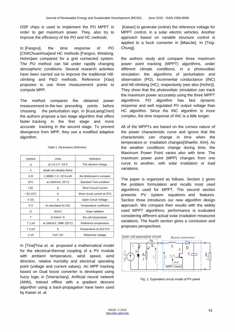
Table 1. Parameters Definition
Symbol Units Definition
q q=1.6.1 0 −19 C The electron charge
n diode non-ideality factor
K B 1.38065·1 0 −23 N.m/K the Boltzmann’s constant
STC at (1kW/m2, 25°C) Standard Test condition
I SC A Short Circuit Current
I SC,STC A Short circuit current at STC
V OC V Open Circuit Voltage
K 0 % calculated for ISC Temperature coefficient
G W/m2 Solar radiation
T in Kelvin °K the cell temperature
T 1,ref at 1kW/m2, 298K (25°C) Reference temperature
T 2,ref K Temperature at 2nd STC
V ref Vref =5V Reference voltage
In [Tina]Tina et. al. proposed a mathematical model
for the electrical-thermal coupling of a PV module
with ambient temperature, wind speed, wind
direction, relative humidity and electrical operating
point (voltage and current values). An MPP tracking
based on Dual boost converter is developed using
fuzzy logic in [Veerachary]. Artificial neural network
(ANN), trained offline with a gradient descent
algorithm using a back-propagation have been used
by Kaiser et. al.
[Kaiser] to generate (online) the reference voltage for
MPPT control, in a solar electric vehicles. Another
approach based on variable structure control is
applied to a buck converter in [MiaoJie]. In [Ting-
Chung],
the authors study and compare three maximum
power point tracking (MPPT) algorithms, under
different climate conditions, in a photovoltaic
simulation: the algorithms of perturbation and
observation (PO), incremental conductance (INC)
and hill climbing (HC), respectively (see also [Hohm]).
They show that the photovoltaic simulation can track
the maximum power accurately using the three MPPT
algorithms. PO algorithm has fast dynamic
response and well regulated PV output voltage than
HC algorithm. Since the INC algorithm is more
complex, the time response of INC is a little longer.
All of the MPPTs are based on the convex nature of
the power characteristic curve and ignore that the
characteristic can change in time when the
temperature or irradiation changes[Shaefer, Kim]. As
the weather conditions change during time, the
Maximum Power Point varies also with time. The
maximum power point (MPP) changes from one
curve to another, with solar irradiation or load
variations.
The paper is organized as follows. Section 1 gives
the problem formulation and recalls most used
algorithms used for MPPT. The second section
presents PV system equations and features.
Section three introduces our new algorithm design
approach. We compare their results with the widely
used MPPT algorithms; performance is evaluated
considering different actual solar irradiation measured
variations. The fourth section gives a conclusion and
proposes perspectives.
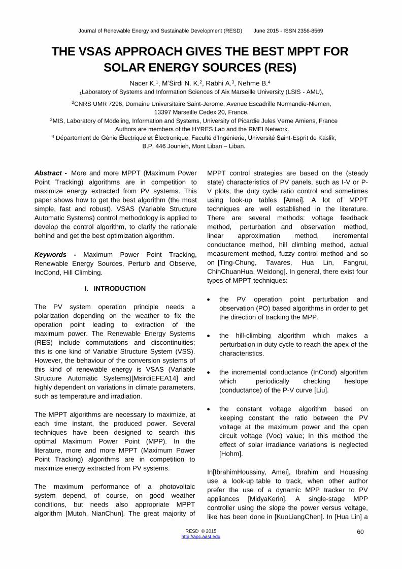
Fig .1. Equivalent circuit model of PV panel

Journal of Renewable Energy and Sustainable Development (RESD) June 2015 - ISSN 2356-8569
62 RESD © 2015 http://apc.aast.edu
II. PV SYSTEMS CONTROL
A. Solar Energy Sources
In this section we present the models of the PV systems. The simulation of the energy behavior of RES (Renewable Energy Source) is developed and several control methods and parameters can be analyzed. The goal is to obtain a good model of the process and to achieve a realistic simulation to enable us to check and validate our approach of Optimal MPPT and control. 1. The Solar irradiation Model
The electric power operating by a PV panel depends on the irradiation intensity of the sun shining, and the temperature of the PV cells. The simplest solar radiation, perturbation free, model that can be used is the following, from (roughly) 7h-19h, the period of sunshine. At the top of the sinusoid, the maximum power is assumed to be 1kw/m², at the time 13 hours. The sunless period is 19h-31h [schijndel1, Sallem]. Note that the wave is assumed piecewise sinusoidal. The solar radiation is represented by the following expression:
G𝑆 = {G𝑆−𝑝𝑖𝑐sin ( 2πt
3600) if t ∈ [ 7h, 19h ] (1)
The electric diagram is equivalent to an average PV
cell as shown in figure 1
(a)
(b)
Fig .2. a) Measurement of Solar irradiance taken for a day;
b) Temperature taken for a day
2. Photovoltaic Systems Model and characteristics
A PhotoVoltaic Generator consists of a group of PV
modules electrically connected in series or parallel or
series-parallel combinations with each other in a
RES to generate required currents and voltages
[MsirdiEFEA14, Liu].
The model is a photo-current source IL one diode
with as reverse saturation current I0 , and a serial
resistance RS , representing the PV cell resistance.
The circuit is connected to the load ( R L ) trough a
converter in order to adjust (adapt) the operating
voltage and current of the PV panel at optimal values
to maximize the harnessed power and transmit it. The
control has to tracks the Maximum Power Point.
The equations describing the I(V) relationship
between the current and voltage of a solar cell are
given by (2), with the parameters defined in Table1
[Shaefer, Hsiao, Walker].
𝐼 = 𝐼𝐿 − 𝐼0 [exp (𝑞(𝑉−𝑅𝑠𝐼
𝑛𝐾𝐵𝑇𝑠) − 1] −
𝑉+𝑅𝑠𝐼
𝑅𝑃 (2)
𝐼0 = 𝐼0(𝑇1) [exp (𝑉𝑂𝐶(𝑇1,𝑟𝑒𝑓)
𝑛𝐾𝐵𝑇1,𝑟𝑒𝑓/𝑞) − 1] (3)
The internal serial resistance RS relative to one cell in
open circuit voltage VOC is:
𝑅𝑆 = −𝑑𝑉
𝑑𝐼⎥𝑉𝑂𝐶 − (
𝑛𝐾𝑜𝑇1,𝑟𝑒𝑓
𝑞)
/ 𝐼0(𝑇1,𝑟𝑒𝑓) exp(𝑉𝑂𝐶(𝑇1,𝑟𝑒𝑓)
𝑛𝐾𝐵𝑇1,𝑟𝑒𝑓/𝑞)
(4)
The PV output voltage of the serial cells can be
expressed as V:
𝑉 = 𝑁𝑆𝑛𝐾𝐵𝑇
𝑞𝑙𝑛(
𝐼𝑆𝐶−𝐼
𝑞𝐼0) (5)
IL varies as a function of the ambient temperature T and of the solar radiation G as:
𝐼L= 𝐼L(𝑇1,𝑟𝑒𝑓)+ 𝐾𝑜(𝑇 − 𝑇1,𝑟𝑒𝑓) (6)
Journal of Renewable Energy and Sustainable Development (RESD) June 2015 - ISSN 2356-8569
63 RESD © 2015 http://apc.aast.edu
With 𝐾𝑜 =𝐼𝑆𝐶(𝑇2,𝑟𝑒𝑓)−𝐼𝑆𝐶(𝑇1,𝑟𝑒𝑓)
𝑇2,𝑟𝑒𝑓−𝑇1,𝑟𝑒𝑓 (7)
𝐼L= 𝐼STC(𝑇1,𝑟𝑒𝑓,𝑆𝑇𝐶)𝐺𝑆
𝐺𝑆𝑇𝐶 (8)
The PV system exhibits a nonlinear I(V) characteristic
which depend on the temperature and the solar
radiation which vary during a day, for exemple, as
shown by the figure TempRadiation; where a) and b)
show the profile of real irradiation measured and
temperature for one day.
The photovoltaic Panel considered, in this paper,
contains 36 photovoltaic cells connected in series. To
track the Maximum Power Point (MPPT) and achieve
the optimum matching, a good control of the DC-DC is
necessary. As the temperature, insulation and load
vary, an algorithm is used to ensures that the PV
module always operates at its maximum power point.
The boost converter operation principle is the one of
Variable Structure System (VSS). The Switching
frequency of the Boost IGBT (changing s) is in general
around fsw = 1/Ts =20kHz . We will try to use, in the
comparative analysis different frequency values.
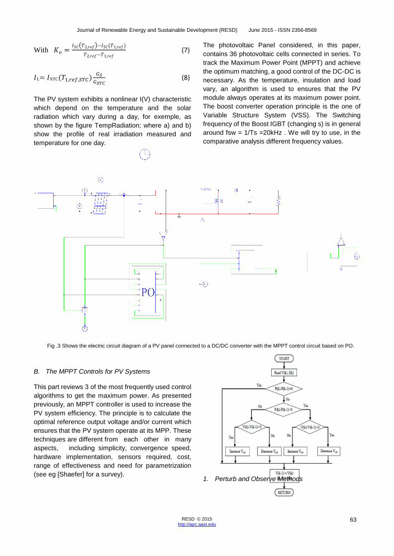
Fig .3 Shows the electric circuit diagram of a PV panel connected to a DC/DC converter with the MPPT control circuit based on PO.
B. The MPPT Controls for PV Systems
This part reviews 3 of the most frequently used control
algorithms to get the maximum power. As presented
previously, an MPPT controller is used to increase the
PV system efficiency. The principle is to calculate the
optimal reference output voltage and/or current which
ensures that the PV system operate at its MPP. These
techniques are different from each other in many
aspects, including simplicity, convergence speed,
hardware implementation, sensors required, cost,
range of effectiveness and need for parametrization
(see eg [Shaefer] for a survey).
1. Perturb and Observe Methods
Journal of Renewable Energy and Sustainable Development (RESD) June 2015 - ISSN 2356-8569
64 RESD © 2015 http://apc.aast.edu
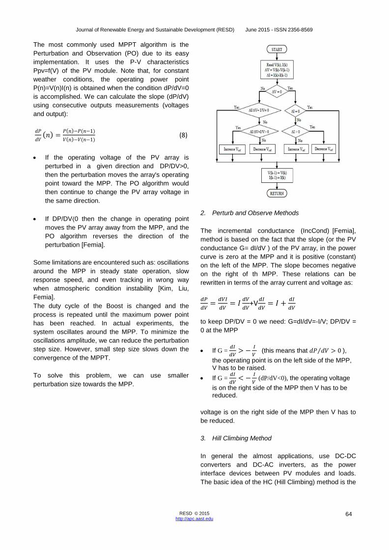
The most commonly used MPPT algorithm is the
Perturbation and Observation (PO) due to its easy
implementation. It uses the P-V characteristics
Ppv=f(V) of the PV module. Note that, for constant
weather conditions, the operating power point
P(n)=V(n)I(n) is obtained when the condition dP/dV=0
is accomplished. We can calculate the slope (dP/dV)
using consecutive outputs measurements (voltages
and output):
𝑑𝑃
𝑑𝑉(𝑛) =
𝑃(𝑛)−𝑃(𝑛−1)
𝑉(𝑛)−𝑉(𝑛−1) (8)
If the operating voltage of the PV array is
perturbed in a given direction and DP/DV>0,
then the perturbation moves the array's operating
point toward the MPP. The PO algorithm would
then continue to change the PV array voltage in
the same direction.
If DP/DV⟨0 then the change in operating point
moves the PV array away from the MPP, and the
PO algorithm reverses the direction of the
perturbation [Femia].
Some limitations are encountered such as: oscillations
around the MPP in steady state operation, slow
response speed, and even tracking in wrong way
when atmospheric condition instability [Kim, Liu,
Femia].
The duty cycle of the Boost is changed and the
process is repeated until the maximum power point
has been reached. In actual experiments, the
system oscillates around the MPP. To minimize the
oscillations amplitude, we can reduce the perturbation
step size. However, small step size slows down the
convergence of the MPPT.
To solve this problem, we can use smaller
perturbation size towards the MPP.
2. Perturb and Observe Methods
The incremental conductance (IncCond) [Femia],
method is based on the fact that the slope (or the PV
conductance G= dI/dV ) of the PV array, in the power
curve is zero at the MPP and it is positive (constant)
on the left of the MPP. The slope becomes negative
on the right of th MPP. These relations can be
rewritten in terms of the array current and voltage as:
𝑑𝑃
𝑑𝑉=
𝑑𝑉𝐼
𝑑𝑉= 𝐼
𝑑𝑉
𝑑𝑉+V
𝑑𝐼
𝑑𝑉= 𝐼 +
𝑑𝐼
𝑑𝑉
to keep DP/DV = 0 we need: G=dI/dV=-I/V; DP/DV =
0 at the MPP
If G = 𝑑𝐼
𝑑𝑉> −
𝐼
𝑉 (this means that 𝑑𝑃 𝑑𝑉 > 0 ⁄ ),
the operating point is on the left side of the MPP, V has to be raised.
If G = 𝑑𝐼
𝑑𝑉< −
𝐼
𝑉 (dP/dV<0), the operating voltage
is on the right side of the MPP then V has to be reduced.
voltage is on the right side of the MPP then V has to
be reduced.
3. Hill Climbing Method
In general the almost applications, use DC-DC
converters and DC-AC inverters, as the power
interface devices between PV modules and loads.
The basic idea of the HC (Hill Climbing) method is the

Journal of Renewable Energy and Sustainable Development (RESD) June 2015 - ISSN 2356-8569
65 RESD © 2015 http://apc.aast.edu
same as P&O method. It tests if P(n) is greater than
P(n-1) or not, to reach MPP. The PO method uses
instead a test on dP/dV to determine whether the
maximum power point has been found or not.
However, the HC method uses a test condition on
P(n)-P(n-1) and uses the duty cycle (D) of these
switching mode power interface devices as the
decision action parameter for the maximum power
point tracking. The figure7 shows a flow diagram of
the hill climbing algorithm.
4. The Proposed VSAS-MPPT Algorithms
The desired objective to get is that the MPP reached
when the maximum power is obtained (P(t)=Pmax
and dP/dt=0). The power is function of the voltage V,
the current I and the time t, then the required
Maximum Power Point to Track is really defined
by the following objective function:
𝑑𝑃
𝑑𝑡=
𝑑𝑉𝐼
𝑑𝑡= 𝐼
𝑑𝑉
𝑑𝑡+ 𝑉
𝑑𝐼
𝑑𝑡= 0 (8)
Let us consider the control in case of discrete time,
then the fetched MPPT may be defined by ΔP(k)=0,
{
∆𝐼 = 𝐼𝑃𝑉(𝑘) − 𝐼𝑃𝑣(𝑘 − 1)
∆𝑉 = 𝑉𝑃𝑉(𝑘) − 𝑉𝑃𝑉(𝑘 − 1)
∆𝑃 = 𝑃𝑃𝑉(𝑘) − 𝑃𝑃𝑉(𝑘 − 1)
𝑃𝑃𝑉(𝑘) = 𝑉𝑃𝑉(𝑘). 𝐼𝑃𝑉
∆𝑃(𝑘) = 𝐼(𝑘). ∆𝑉(𝑘) + 𝑉(𝑘). ∆𝐼(𝑘) ∆𝑃(𝑘) = 𝐼(𝑘). 𝑢1(𝑘) + 𝑉(𝑘). 𝑢2(𝑘) The two control variables are then u1(k)= ∆V(k) (the
voltage variation) and u2(k)=∆I(k) (the current
variation).
5. RUCA: Robust Unified Control Algorithm
For the proposed RUCA algorithm, both control inputs
can be used if we look for adjusting both variables (V
and I), either at each control step or alternatively. It
can be noticed that the previous algorithms can be
considered as particular cases of this one,
when simplifying the proposed control method. P
max is a constant chosen greater than the maximum
power in any weather condition Pmax≥P(t) . Let us
then consider the Lyapunov like function
W(t) = ( 𝑃2𝑚𝑎𝑥 − P(t)2 ) > 0
which is strictly positive everywhere ( ∀t, ∀I, ∀V ). The
derivative of the proposed Lyapunov function W(t)=(
P^2〗_max-〖P(t)〗^2 )>0 , is
�̇�(t) = −P(t)𝑑𝑃(𝑡)
𝑑𝑡= −P(t)(𝐼
𝑑𝑉
𝑑𝑡+ 𝑉
𝑑𝐼
𝑑𝑡)
�̇�(t) = −𝐼2𝑉𝑑𝑉
𝑑𝑡− 𝑉2𝐼
𝑑𝐼
𝑑𝑡)
t can be made negative by choosing the appropriate
control laws u1(k)= ∆V(k)and u2(k)=∆I(k) to get a
decreasing Lyapunov function. The RUCA uses two
control inputs which can be done either
simultaneously or alternatively or one of them can be
frozen depending on the needed voltage or current.
Choosing
u1(k)= Kα∆P(k)sign(∆V(k))
u2(k)=K_2 α_2 ∆P(k)sign(∆I(k))
ensures that W (̇t)<0 and then the convergence of the
RUCA algorithm. This proves, theoretically also the
convergence of the MEPO algorithm which follows.
We can use both inputs or only one of them either, in
a first case u1(k)= Kα∆P(k)sign(∆V(k)), or in the
second case u2(k)=K_2 α_2 ∆P(k)sign(∆I(k)). In
control context, the previously presented MPPT
controllers use only one control variable u1 or u2 and
impose the second to be zero. The implementation of
the proposed enhanced MPPT controller RUCA can
be summarised as follows:
The reference voltage is set be equal to the
double of the PV open circuit voltage.
Measurement of the of input signals (PV voltage,
Journal of Renewable Energy and Sustainable Development (RESD) June 2015 - ISSN 2356-8569
66 RESD © 2015 http://apc.aast.edu
PV current and Load voltage).
Estimate the PV power at the sample time k : PPV
(k)= Ipv(k).Vpv(k)
Calculate the PV current and PV power
increments (see equation eq:optim).
6. MEPO: Modified Enhanced PO Algorithm
If we take as input u1(k) and put a constant current
u2(k)=0 , which means that the voltage is perturbed
and the current is fixed u2(k)= ∆I(k)=0 , we are in the
same configuration as the PO algorithm. We propose,
as a Modified Enanced PO Algorithm which will be
more robust, the reference voltage is given by
Vref=Vk+ Kα∆P(k)sign(∆V(k)) Knowing that we
impose ∆I(k)=0 , we get for the proposed MEPO
control algorithm we take u1(k)= Kα∆P(k)sign(∆V(k))
and u2(k)= ∆I(k)=0 . The reference voltage Vref(k) is
calculated as below, where α is a gain weighting the
perturbation variation step. Note that ΔVref=
αsign(∆P(k)∆V(k)) produces exactly the same result
as the classical PO algorithm with a much simpler
implementation. This method gives an enhanced
variable step size algorithm. The step size is adjusted
in proportionally to the power variation produced in the
previous step. The adaptive step adjustment gain K is
used with ∆P(k), for weighting the variation (Voltage
perturbation) step. It is useful for oscillation
avoidance, fast convergence and noise sensitivity
reduction. We can also use only the control variable
u2 (k)= ∆I(k) (and put u1(k)=0 ), the current is
perturbed and the voltage is fixed ∆V(k)=0.
C. Comparative Simulations and Tests
The simulation was performed under Psim software
as shown in figure 3. The physical model of a PV
panel is used. The panel is considered to have 36
cells. A boost converter is built using a MOSFET as a
switch. The load is a 100 Ω resistor. The algorithms
are implemented in a C block and the duty cycle is
calculated from Vref using another C block. The
actual, measured irradiation and panel temperature
are read from a txt file as inpt to the simulation.
1. MPPT Alghorithms Comparison
In this study we compare four MPPT algorithms under
the same experimental conditions. The first algorithm
called P&O stands for perturb and observe. The
second algorithm called IncCond stands for
incremental conductance. The third algorithm called
MEPO stands for Modified Enhanced Perturb and
Observe (from VSAS- MPPT). And the fourth
algorithm called RSMCA (from VSAS-MPPT
approach) stands for Robust Sliding Mode Control
Algorithm. Note that RUCA algorithm is simply
combining use of the two VSAS MPPTs alternatively.
The comparison is made under changing values of
irradiation and temperature. Two cases are
considered: first we update the irradiance and
temperature each time without interpolation to create
sudden variation in power output, second we
interpolate the values of irradiance and temperature to
create quasi-continuous irradiation and temperature.
At the end we use real measured data for simulation.
In this study we focus on the PWM commutation
frequency of the MPPT algorithm.
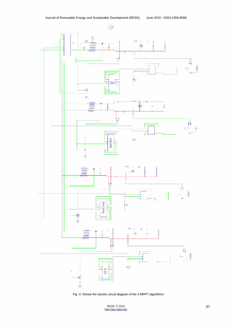
2. Zero Order Hold Interpolation Analysis
We perform many simulations with varying irradiance
and temperature. The values are not interpolated
causing sudden variation in power output. For high
MPPT algorithm frequencies (25Hz, 50Hz, 100Hz) no
difference in power output is noted between the four
algorithms. After a change in environmental conditions
that makes an increase in power output, MEPO
algorithm may present an oscillation because it is
based on the value of DP and not on the sign of DP.
At high irradiances, the RSMCA algorithm present
oscillation caused by the gain in calculation of
Vref.For low frequencies (5Hz, 10Hz, 12.5Hz), the
MEPO and the RSMCA algorithms excel the PO and
IncCond algorithms. We can see in figure 2 that the
PO power and the IncCond power are too far from the
maximum power that can be generated from the
panel. This is due to the fixed or small step size of the
Vref. We must recall that the MEPO and the
RSMCA algorithms also converge rapidly to the
maximum power after the start of the simulation.
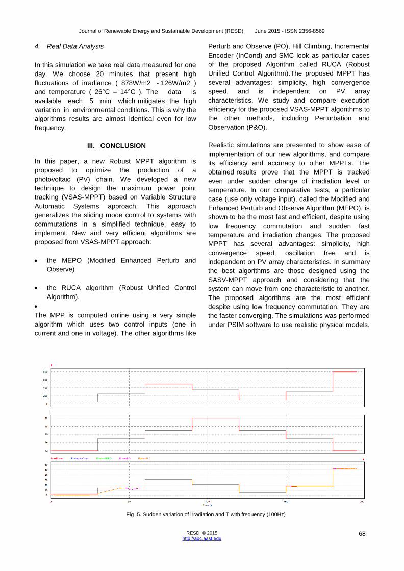
3. First Order Interpolation Analysis
When interpolating data for irradiance and
temperature (approaching real conditions), we can
see that that the difference between PO and IncCond
algorithms and MEPO and RSMCA algorithms are
emphasized when we have high variation of
environmental conditions and low algorithm
frequency.
Journal of Renewable Energy and Sustainable Development (RESD) June 2015 - ISSN 2356-8569
67 RESD © 2015 http://apc.aast.edu
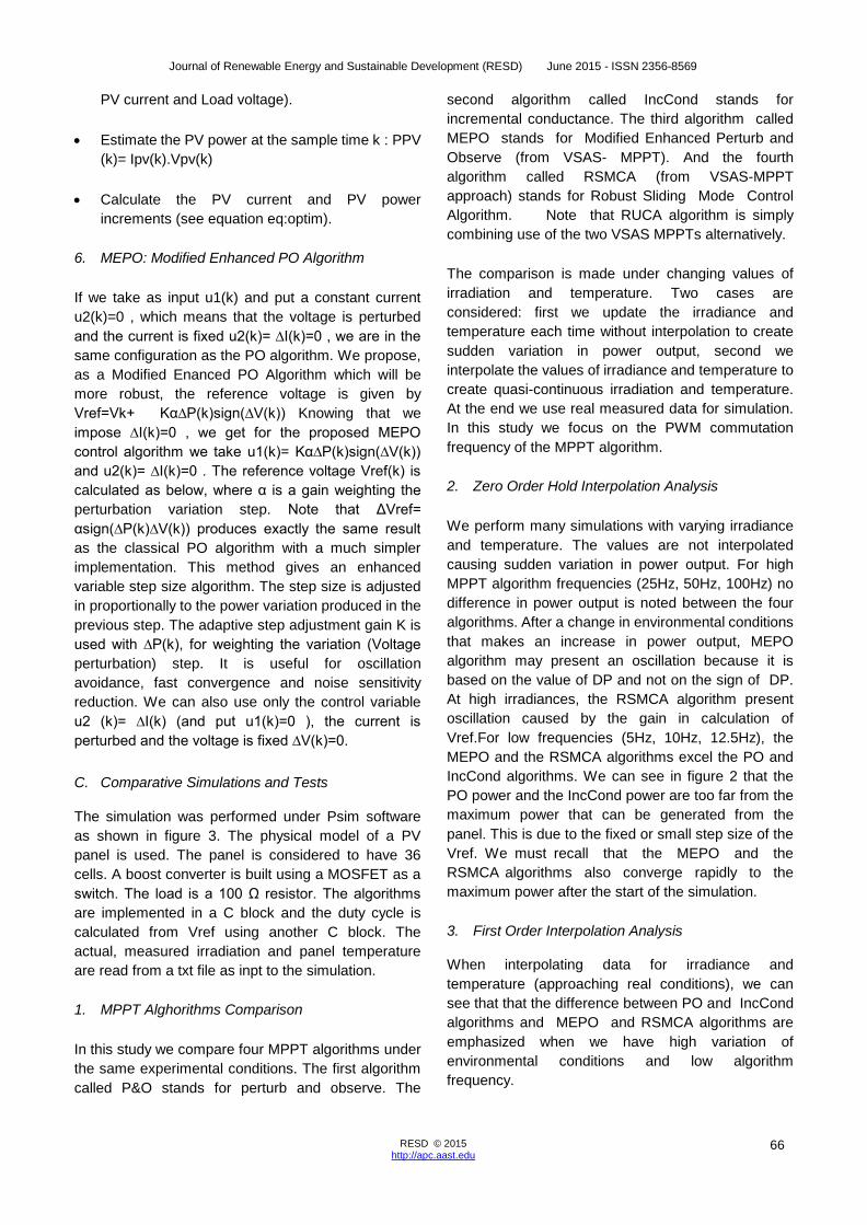
Fig .4. Shows the electric circuit diagram of the 4 MPPT algorithms
Journal of Renewable Energy and Sustainable Development (RESD) June 2015 - ISSN 2356-8569
68 RESD © 2015 http://apc.aast.edu
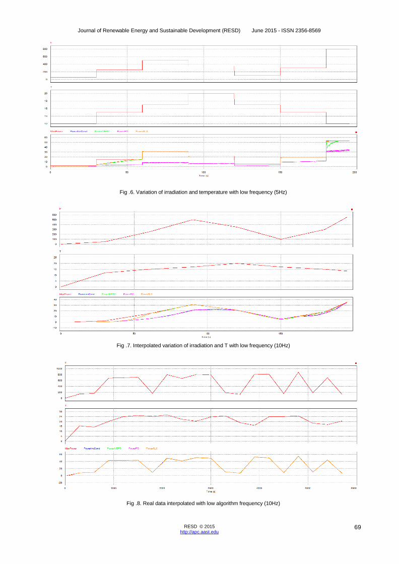
4. Real Data Analysis
In this simulation we take real data measured for one
day. We choose 20 minutes that present high
fluctuations of irradiance ( 878W/m2 - 126W/m2 )
and temperature ( 26°C – 14°C ). The data is
available each 5 min which mitigates the high
variation in environmental conditions. This is why the
algorithms results are almost identical even for low
frequency.
III. CONCLUSION
In this paper, a new Robust MPPT algorithm is
proposed to optimize the production of a
photovoltaic (PV) chain. We developed a new
technique to design the maximum power point
tracking (VSAS-MPPT) based on Variable Structure
Automatic Systems approach. This approach
generalizes the sliding mode control to systems with
commutations in a simplified technique, easy to
implement. New and very efficient algorithms are
proposed from VSAS-MPPT approach:
the MEPO (Modified Enhanced Perturb and
Observe)
the RUCA algorithm (Robust Unified Control
Algorithm).
The MPP is computed online using a very simple
algorithm which uses two control inputs (one in
current and one in voltage). The other algorithms like
Perturb and Observe (PO), Hill Climbing, Incremental
Encoder (InCond) and SMC look as particular cases
of the proposed Algorithm called RUCA (Robust
Unified Control Algorithm).The proposed MPPT has
several advantages: simplicity, high convergence
speed, and is independent on PV array
characteristics. We study and compare execution
efficiency for the proposed VSAS-MPPT algorithms to
the other methods, including Perturbation and
Observation (P&O).
Realistic simulations are presented to show ease of
implementation of our new algorithms, and compare
its efficiency and accuracy to other MPPTs. The
obtained results prove that the MPPT is tracked
even under sudden change of irradiation level or
temperature. In our comparative tests, a particular
case (use only voltage input), called the Modified and
Enhanced Perturb and Observe Algorithm (MEPO), is
shown to be the most fast and efficient, despite using
low frequency commutation and sudden fast
temperature and irradiation changes. The proposed
MPPT has several advantages: simplicity, high
convergence speed, oscillation free and is
independent on PV array characteristics. In summary
the best algorithms are those designed using the
SASV-MPPT approach and considering that the
system can move from one characteristic to another.
The proposed algorithms are the most efficient
despite using low frequency commutation. They are
the faster converging. The simulations was performed
under PSIM software to use realistic physical models.
Fig .5. Sudden variation of irradiation and T with frequency (100Hz)
Journal of Renewable Energy and Sustainable Development (RESD) June 2015 - ISSN 2356-8569
69 RESD © 2015 http://apc.aast.edu
Fig .6. Variation of irradiation and temperature with low frequency (5Hz)
Fig .7. Interpolated variation of irradiation and T with low frequency (10Hz)
Fig .8. Real data interpolated with low algorithm frequency (10Hz)
Journal of Renewable Energy and Sustainable Development (RESD) June 2015 - ISSN 2356-8569
70 RESD © 2015 http://apc.aast.edu
REFERENCES
[1] M’Sirdi, N. K., Nehme, B. and Rabhi, A.
(November 2014) The Best MPPT Algorithms by
VSAS approach for Renewable Energy Sources
(RES). EFEA 2014, international IEEE
conference PARIS.
[2] Mutoh, N. Ohno, M. and Inoue, T. (June 2006) A
method for MPPT control while searching for
parameters corresponding to weather conditions
for PV generation systems. IEEE Transactions on
Industrial Electronics, vol.53, no.4, pp.1055-
1065.
[3] Wang, N. C., Sun, Z., Yukita, K., Goto, Y. and
Ichiyanagi, K. (March 2010) Research of PV
model and MPPT methods in Matlab. Asia-
Pacific Power and Energy Engineering
Conference (APPEEC 2010), pp.1-4, 28-31.
[4] Amei, K., Takayasu, Y., Ohji, T. and Sakui, M.
(2002) A Maximum Power Control of Wind
Generator System Using a Permanent Magnet
Synchronous Generator and a Boost Chopper
Circuit. IEEE Power Conversion Conference, vol.
3, , pp. 1447- 1452.
[5] Yu, T. C., and Shen,Y.T. (Nov. 2009) Analysis
and Simulation of Maximum power point tracking
for photovoltaic systems. Proceedings of the
30th ROC Symposium on Electrical Power
Engineering, Taoyuan, Taiwan, pp. 92-96.
[6] Tavares, C. A. P., Leite, K. T. F., Suemitsu, W. I.
and Bellar, M. D. (Nov. 2009) Performance
Evaluation of Photovoltaic Solar System with
Different MPPT Methods, Industrial Electronics,
2009. IECON '09. 35th Annual Conference of
IEEE, pp.719-724.
[7] Hua, C., Lin, J., Shen, C. (1998) Implementation
of DSP-Controlled Photovoltaic System with
Peak Power Tracking. IEEE Trans. On Industrial
Electronics, Vol. 45, No. 1, pp. 99-107.
[8] Liu, F., Kang,Y., Zhang, Y., and Duan, S., (June
2008) Comparison of P&O and hill climbing
MPPT methods for grid-connected PV converter.
3rd IEEE Conference on Industrial Electronics
and Applications, (ICIEA 2008), pp.804-807, 3-5.
[9] Hua, C. C., Lin, J. R. (June 2001) Fully Digital
Control of Distributed Photovoltaic Power
Systems. Proceedings of IEEE International
Symposium on Industrial Electronics (ISIE 2001),
vol. 1, pp. 1-6.
[10] Xiao,W. (July 2003) A Modified Adaptive Hill
Climbing Maximum Power Point Tracking
Control Method for Photovoltaic Power System.
Master Thesis, The University of British
Columbia,
[11] Liu X., Lopes L.A.C. ( June 2004) An
Improved Perturbation and Observation
Maximum Power Point Tracking Algorithm for PV
Arrays. Power Electronics Specialists
Conference, 2004. PESC 04. 2004 IEEE 35th
Annual Volume 3, pp. 2005 – 2010.
[12] Hohm, D. P., Ropp, M. E. (January 2003)
Comparative Study of Maximum Power Point
Tracking Algorithms. Progress in
Photovoltaics: Research and Applications, vol.
11, no. 1, pp. 47–62,
[13] Ibrahim, H. E. and Houssiny, F. F., (August
1999) Microcomputer Controlled Buck Regulator
for Maximum Power Point Tracker for DC
Pumping System Operates from Photovoltaic
System. Proceedings of the IEEE International
Fuzzy Systems Conference, Vol. 1, pp. 406-411.
[14] Midya, P., Kerin, P. T., Turnbull, R. J., Reppa, R.
and Kimball, J. (1996) Dynamic Maximum Power
Point Tracker for Photovoltaic Applications.
Proceedings of the IEEE Power Electronics
Specialists Conference, PESC, Vol. 2, pp. 1710-
1716.
[15] Kuo, Y. C., Liang, T. J. and Chen, F. C. (2001)
Novel Maximum-Power-Point-Tracking Controller
for Photovoltaic Energy Conversion System.
IEEE Transactions on Industrial Electronics, Vol.
48, pp. 594- 601.
[16] Kaiser, M., Aditya, S. and Mazumder, R.( July
2006) Performance Evaluation of a Maximum
Power Point Tracker (MPPT) for Solar Electric
Vehicle Using Artificial Neural Network. Daffodil
International University Journal Of Science And
Technology, vol. 1, issue 1.
[17] Xiao, W. and Dunford, W. G. (2004) A modified
adaptive hill climbing MPPT method for
photovoltaic power systems,” 35th. Annual IEEE

Journal of Renewable Energy and Sustainable Development (RESD) June 2015 - ISSN 2356-8569
71 RESD © 2015 http://apc.aast.edu
Power Electron. Specialists Conf., pp. 1957-
1963.
[18] Tina, G.M. and Scrofani, S.( May 2008) Electrical
and Thermal Model for PV Module Temperature
Evaluation. IEEE Electrotechnical Conference.
pp. 585-590.
[19] Schaefer, J. (June 1990) Review of Photovoltaic
Power Plant Performance and Economics, IEEE
Trans. Energy Convers., vol. EC-5, pp 232-238.
[20] Tse, K. K., Ho, M. T., Henry, S., Chung, H. and
Hui, S. Y. (November 2002) A Novel Maximum
Power Point Tracker for PV Panels Using
Switching Frequency Modulation. IEEE
Transactions on Power Electronics, Vol. 17,
No.6.
[21] Calavia, M., Perie, J.M., Sanz, J.F. and Sallan, J.
(March 2010) Comparison of MPPT Strategies
for Solar Modules. International Conference on
Reneweble Energies and Power Quality,
Granada (Spain),
[22] Femia, N., Petrone, G., Spagnuolo, G. and Vitelli,
M. (June 2004) Optimizing duty-cycle
perturbation of P&O MPPT technique. Power
Electronics Specialists Conference, 2004. PESC
04. 2004 IEEE 35th Annual Volume 3, pp.1939
–1944.
[23] Femia, N., Petrone, G., Spagnuolo, G. and
Vitelli, M. (July 2005) Optimization of
Perturb and Observe Maximum Power Point
Tracking Method. IEEE Transactions on Power
Electronics, Vol. 20, No. 4.
[24] Fangrui, L., Shanxu, D., Fei, L., Bangyin,
L. and Yong, K. (July 2008) A Variable Step
Size INC MPPT Method for PV Systems. IEEE
Transactions on Industrial Electronics, Vol.
55, No. 7.
[25] Chao, K.H. and Lee, Y.H. (Volume
2012) A Maximum Power Point Tracker with
Automatic Step Size Tuning Scheme for
Photovoltaic Systems. International Journal of
Photoenergy.
[26] Zoua,Y., Yua,Y., Zhangb, Y. and Luc, J. (2012)
MPPT Control for PV Generation System Based
on an Improved Inccond Algorithm. Procedia
Engineering Vol. 29, pp.105-109.
[27] Chen, C. H. (2002) Maximum Power
Tracking for Photovoltaic Power System. In
Conf. Record of the 37th IAS Annual
MeetingInd. Applicat. Conf., pp. 1035-1040.
[28] Walker, G. (2001) Evaluating MPPT Converter
Topologies Using a MATLAB PV Model. Journal
of Electrical & Electronics Engineering,
Australia, IEAust, vol.21, No. 1, pp.49-56.
[29] Veerachary, M., Senjyu, T. and Uezato,
K. (July 2002) Feedforward Maximum Power
Point Tracking of PV Systems Using Fuzzy
Controller. IEEE Transactions on Aerospace
and Electronic Systems,Vol. 38, 3,
969-981.
[30] Miao, Z., Jie, W. et al.,( 2004) The
Application of Slide Technology in PV Maximum
Power Point Tracking System. Fifth
WorldCongress on Intelligent Control and
Automation, WCICA.
[31] Kim,T. Y., . Ahn, H. G., Park, S. K. and Lee, Y. K.
(2001) A Novel Maximum Power Point Tracking
Control for Photovoltaic Power System Under
Rapidly Changing Solar Radiation. In IEEE
International Symp. On Ind. Electron, pp. 1011-
1014.
[32] MATLAB Simulink. Creating Graphical User
Interfaces. Version 7.9 [Online]. Available :
http://www.mathworks.com/access/ helpdesk/
help/ techdoc / creating_guis/ bqz79mu.html.