the w. m. keck observatory laser guide star adaptive ... · adaptive optics (ao) systems have been...
TRANSCRIPT

297
Publications of the Astronomical Society of the Pacific, 118:297–309, 2006 February� 2006. The Astronomical Society of the Pacific. All rights reserved. Printed in U.S.A.
The W. M. Keck Observatory Laser Guide Star Adaptive Optics System: Overview
Peter L. Wizinowich, David Le Mignant, Antonin H. Bouchez,1 Randy D. Campbell, Jason C. Y. Chin,Adam R. Contos,2 Marcos A. van Dam, Scott K. Hartman, Erik M. Johansson, Robert E. Lafon,
Hilton Lewis, Paul J. Stomski, and Douglas M. Summers
W. M. Keck Observatory, 65-1120 Mamalahoa Highway, Kamuela, HI 96743; [email protected]
andCurtis G. Brown, Pamela M. Danforth, Claire E. Max,3 and Deanna M. Pennington
Lawrence Livermore National Laboratory, P.O. Box 808, Livermore, CA 94550
Received 2005 September 12; accepted 2005 October 31; published 2006 February 9
ABSTRACT. The Keck Observatory began science observations with a laser guide star adaptive optics system,the first such system on an 8–10 m class telescope, in late 2004. This new capability greatly extends the scientificpotential of the Keck II Telescope, allowing near–diffraction-limited observations in the near-infrared using naturalguide stars as faint as 19th magnitude. This paper describes the conceptual approach and technical implementationfollowed for this system, including lessons learned, and provides an overview of the early science capabilities.
1. INTRODUCTION
Adaptive optics (AO) systems have been in use on astro-nomical telescopes since the early 1990s (Graves et al. 1994;Rousset et al. 1994; Rigaut et al. 1998). From the beginning,astronomers recognized the limitations of AO due to the needto use relatively bright stars to measure the wave-front distor-tions introduced by Earth’s atmosphere. To increase the verylimited sky coverage of these systems, they have thereforelooked for ways to create their own beacons using lasers. Themost feasible of these approaches for very large telescopes isto use a sodium-wavelength laser to excite the sodium atomsin Earth’s mesosphere (Foy & Labeyrie 1985; Thompson &Gardner 1987). Although experiments with various lasers havebeen performed at a number of observatories, only a few laserguide star (LGS) based science papers have been published(McCullough et al. 1995; Hackenberg et al. 2000; Perrin etal. 2004), and until recently only the Lick 3 m telescopesodium LGS system has been performing LGS observationson a regular basis (Max et al. 1997). The Lick system wasjoined in late 2004 by an operational sodium LGS system onthe Keck II Telescope.
The W. M. Keck Observatory consists of two 10 m diameteroptical/infrared telescopes separated by 85 m, located on thesummit of Mauna Kea in Hawaii. Natural guide star (NGS) AO
1 Current address: Caltech Optical Observatories, Mail Code 105-24, Cal-ifornia Institute of Technology, 1200 East California Boulevard, Pasadena, CA91125.
2 Current address: Ball Aerospace, 10 Longs Peak Drive, Broomfield, CO80021.
3 Current address: Center for Adaptive Optics, University of California, SantaCruz, 1156 High Street, Santa Cruz, CA 95064.
systems have been in operation on the Keck II and Keck ITelescopes since 1999 (Wizinowich et al. 2000a, 2000b) and2000, respectively. The science instruments behind the AOsystem have included KCAM, a simple near-infrared imagingengineering camera; NIRSPEC, a near-infrared spectrograph(McLean et al. 1998); NIRC2, a near-infrared camera designedexplicitly for AO (K. Matthews et al. 2006, in preparation); aninterferometer that combines the light from both telescopes(Colavita et al. 2004); and OSIRIS, an OH-suppression infraredintegral field spectrograph (Larkin et al. 2003).
The Keck II AO system was designed from the start to bean LGS system. The laser was fabricated by Lawrence Liv-ermore National Laboratory (LLNL) and delivered in 1998(Friedman et al. 1998) to a laboratory at Keck headquarters,where it was further engineered by a team of LLNL and Keckpersonnel. It was integrated with the telescope in 2001 in timefor an end-of-the-year first projection of the laser onto the sky.This milestone was followed by continued laser and LGS AOdevelopment. The first closed-loop tests with the laser occurredin late 2003. Shared-risk science observations began in late2004, and 30 LGS AO science nights have been allocated inthe second half of 2005.
The nature and limitations of a sodium-wavelength LGSrequire numerous modifications with respect to an NGS-basedAO system. Section 2 discusses these LGS AO issues and theconceptual approaches we chose to address them, as well asthe technical implementation of the resulting LGS components.Section 3 describes the laser, associated operational issues, andthe laser guide star. We then describe the LGS AO operations,including observing strategy (§ 4) and the early science ca-pabilities (§ 5). Implementing the first LGS AO system on a

298 WIZINOWICH ET AL.
2006 PASP,118:297–309
Fig. 1.—Schematic representation of the Keck LGS AO system components.The light from the telescope is reflected off a TTM and DM. The infraredlight is transmitted through an IR-transmissive dichroic to the science instru-ment. The visible light from the NGS and LGS is reflected off this dichroic.The NGS light is reflected off a sodium-transmissive dichroic to a TTS andLBWFS mounted on an (x, y, z) TSS. The transmitted LGS light goes to aWFS mounted on a focus stage. The resulting control loops are described inthe text.
large telescope has presented numerous challenges, and thispaper attempts to share the lessons learned in this process. Aseparate paper (van Dam et al. 2006) describes the LGS AOsystem’s performance and algorithms in more detail.
2. IMPLEMENTATION
In order to orient the reader, we first provide a schematic ofthe LGS AO control approach taken in the Keck system. Wethen review, at a schematic level, the LGS AO issues and thesolutions chosen for the Keck system (somewhat as a per-spective on historical development). Finally, we describe thephysical implementation of the Keck system.
2.1. LGS AO Control
A schematic view of the major Keck LGS AO componentsis presented in Figure 1. The NGS and LGS light collected bythe telescope are reflected off the tip-tilt mirror (TTM), thedeformable mirror (DM), and the infrared (IR) transmissivedichroic. The infrared light is transmitted to the science camera.The sodium-wavelength light is transmitted through a sodium-transmissive dichroic to the wave-front sensor (WFS). Sincethe LGS is not at infinity, it comes to a focus after the NGSfocus.
The WFS is mounted on a translation stage to keep it con-jugate to the sodium layer as a function of zenith angle. Thetip-tilt error is used to drive the laser uplink TTM, which inturn offloads to a larger stroke mirror used for laser pointingcorrections. The tip-tilt–removed centroid errors measured bythe WFS go to the wave-front controller that drives the DM.The DM offloads its time-averaged focus to the telescope con-trol system, which pistons the secondary mirror to compensate.
The visible light reflected off the sodium-transmissive di-chroic goes to the tip-tilt sensor (TTS) and low-bandwidthwave-front sensor (LBWFS). A beam-splitter cube transmits80% of the light to the TTS, since tip-tilt needs to be correctedat a high bandwidth, and reflects 20% to the LBWFS. The TTSand LBWFS are mounted on an (x, y, z)-translation stage (TSS)to acquire and track an off-axis NGS.
The tip-tilt error measured by the TTS is used to drive theTTM, which in turn offloads to the telescope pointing. Thefocus error measured by the LBWFS is used to keep the WFSconjugate to the sodium layer. The time-averaged centroid er-rors measured by the LBWFS are used to remove the LGS-induced aberrations by adjusting the WFS centroid offsets. TheLGS reconstructor changes as a function of the laser orientationwith respect to the WFS.
This last point about laser orientation deserves an explan-atory background paragraph, since it is mentioned several timesin the next section and is somewhat unique to Keck. In theKeck II case, the laser projects from the elevation ring of thetelescope. As the telescope moves in elevation, the laser pro-jector and telescope pupil change in orientation with respectto the fixed Nasmyth platform location of the AO system. In
addition, the sky rotates with respect to the AO system as thetelescope moves in azimuth and elevation. The first elementon the AO bench is a derotator, which can be used to keepeither the sky or the pupil fixed with respect to the AO system,but not both. In general, observers prefer to keep the scienceobject orientation fixed on the science instrument, resulting ina changing orientation of the Keck pupil and laser on the WFS.Since the Keck pupil is an irregular hexagonal shape (due toits 36 hexagonal segments), we already had to solve the prob-lem of a rotating pupil for NGS AO (Stomski & Shelton 2000).This is done by continually determining which WFS subap-ertures are illuminated, and building and loading new recon-structor matrices on this basis. The impact of a rotating off-axis laser projection is among the LGS AO issues addressedin the next section. The NGS and LGS reconstructors are dis-cussed in van Dam et al. (2004) and (2006), respectively.
2.2. LGS AO Issues and Approach
An overview schematic of the LGS AO issues and the so-lutions we have chosen is shown in Figure 2.
In NGS AO, the wave-front distortions introduced by theturbulence in Earth’s atmosphere are measured using the lightfrom a star or compact astronomical object. Since the atmo-sphere changes both temporally and spatially, the NGS mustbe bright and near the science target. For the Keck NGS AOsystems, the NGS must be brighter than 14th magnitude andwithin 30� of the science target. This limits NGS AO obser-vations to only a small fraction of the sky. The lack of a

KECK LASER GUIDE STAR AO 299
2006 PASP,118:297–309
Fig. 2.—Solutions tree for LGS implementation issues. LGS-specific issues are shaded in dark gray below their associated parent topic, and their chosen solutionis indicated with an arrow. Individual issues are called out by a number referenced in the text.
bright nearby NGS for a hypothetical science target is shownas item 1 in Figure 2. One solution is to use an LGS, spe-cifically a sodium-wavelength LGS in our case.
As shown in Figure 2, there are complications introducedwhen using an LGS.
Item 2.—The laser spot moves on the sky, due to tilt in-troduced in the upward path by a combination of atmosphericturbulence, laser launch-tube flexure, telescope vibrations,and wind shake. To overcome this LGS spot motion, the laserlaunch optics includes a tip-tilt mirror (referred to as uplinktip-tilt, or UTT) to stabilize laser pointing. The UTT errorsignal is provided by the WFS, which observes the LGS light.The Keck WFS is a high-bandwidth (up to 670 Hz) Shack-Hartmann system with 20 subapertures across the Keck pri-mary mirror.
Item 3.—Rapid atmospheric turbulence–induced changes inthe wave front are corrected by changing the shape of a DMusing the tip-tilt–removed wave front measured by this WFS,in the same way as for NGS AO.
Item 4.—In NGS mode, the WFS is located in the same focalplane as the science instrument (i.e., conjugate to infinity),which ensures that the WFS drives the DM to maintain focuson the science instrument. In LGS mode, the WFS needs tobe conjugate to the sodium layer so that the LGS is in focus
on the WFS. As the telescope moves away from the zenith,the distance to the sodium layer increases, and the WFS focusmust be moved back toward the NGS focus to stay conjugateto the sodium layer. The required focus shift as a function ofzenith angley is given by
2Z(h, y) p fh/(h � f cosy) � f p ( f cosy)/(h � f cosy),
(1)
whereh is the height of the sodium layer above the telescopeat zenith, andf is the focal length of the telescope (f p 150 mfor Keck). Forh p 90 km, the Keck WFS focus shift variesfrom 250 mm at the zenith to 125 mm at a zenith angle of 60�.To avoid having theH-band Strehl ratio degraded by more than10%, the focus must be maintained to an accuracy of 0.17 mm.The approach taken in the Keck system was to mount the WFSon a focus stage that tracks as a function of the zenith angle.
Item 5.—Translating the WFS in focus also changes the dis-tance to the pupil (i.e., the DM). To compensate, one of theelements of the WFS pupil relay optics is translated. This main-tains the pupil size on the WFS lenslet array.
Item 6.—In NGS AO, the reference beacon imaged in eachWFS subaperture is identical, regardless of pupil location. InLGS AO, however, each subaperture sees an elongated image

300 WIZINOWICH ET AL.
2006 PASP,118:297–309
Fig. 3.—Acquisition camera images (left and middle; 60� # 60�) of the Keck LGS at zenith.Left: LGS image with a FWHM of 1�.6 # 2�.0 and an equivalentV magnitude of 9.8.Middle: LGS image taken with the 36 primary-mirror segments unstacked. The laser projector is on the right side of the telescope in theseimages; the side from which the Rayleigh-scattered light can also be seen. The individual segment image closest to the projector can have a FWHM as small as1�.0, while the segment images further away can be seen to be elongated toward the projector. The circled segment image in the middle panel was used to producethe relative density structure vs. altitude plot for the sodium layer (right); a 35 km altitude range is shown.
of the approximately 10–15 km thick layer of sodium illumi-nated by the laser. This is due to perspective elongation as onemoves off the axis of the laser projection telescope. The elon-gation is a function of the distance off the laser projector axisand is in the direction of the laser projector. This is particularlybad in the Keck II laser implementation, since the laser pro-jector is located on the side of the telescope. The subapertureon the far side of the telescope from the projector (∼12 m fromthe projector) exhibits an elongation as long as 3� for a 10 kmthick layer at an altitude of 90 km. Figure 3 (middle) showsan acquisition camera image of this LGS elongation versusdistance obtained by unstacking the 36 primary-mirror seg-ments of the Keck Telescope; the bright spot on the right sideof this image is the Rayleigh-scattered light from air moleculesin the lower atmosphere, indicating the side where the laserprojector is located. This elongation introduces several chal-lenges. One is that the optimal (x, y) gains for each subapertureare functions of the length and direction of the elongation, andthe other is that these gains change as the pupil (and hencelaser projector) rotates. This gain versus position correction ishandled in the LGS wave-front reconstructor, and the recon-structor is updated as the telescope pupil rotates with respectto the AO system. The LGS reconstructor algorithm takes twoinputs to estimate spot size in each subaperture: the FWHMof the laser spot as seen from near the launch telescope, andthe maximum elongation observed at the far edge of the pupil.Both of these are measured nightly from acquisition cameraimages of the unstacked primary-mirror segments. Projectingthe laser from behind the secondary mirror instead of from theside of the telescope would have considerably reduced the com-plexity of this issue (and item 11 below), since the magnitudeof the elongation would be halved and the impact of pupilrotation could be negligible.
Item 7.—The Rayleigh-scattered light could contaminate themeasurements made by the WFS if it reached this sensor. The
Rayleigh light is separated from the LGS light due to the off-axis projection of the laser, and this off-axis Rayleigh light isthen blocked by the field stop in front of the WFS.
Item 8.—Some critical information cannot be obtained fromthe LGS. This information can be provided by a faint NGS.
Item 9.—Unfortunately, the LGS does not provide tip-tiltinformation for the science object, since the laser is deflectedin tip and tilt along both its upward and downward paths. Aseparate TTS observing an NGS can be used to provide thistip-tilt information. NGSs as faint as 19th magnitude can beused with the Keck system’s TTS. The error measured by thissensor is used to drive a fast TTM.
Item 10.—A change in the altitude of the sodium layer lookslike a focus change to the WFS and is therefore applied to theDM. An LBWFS aimed at the NGS that is being used for tip-tilt is employed to sense this error. The WFS focus stage po-sition is adjusted to drive the time-averaged focus measuredby the LBWFS to zero. The new focus-stage position is thenused to reestimate the sodium layer altitude to optimize thefocus-stage tracking rate (Summers et al. 2004).
Item 11.—The wave front measured by the WFS is differentwhen an LGS is used than when an NGS is used. In particular,the LGS elongation mentioned under item 6 above results inthe measurement of aberrations that one does not want to applyto the DM. These are referred to as semistatic, since they changeas the sodium layer thickness or structure changes, as the tele-scope elevation changes, and as the telescope pupil (and hencelaser projector) rotates. In the case of Keck, a LBWFS is usedas a truth sensor to correct for these aberrations. The LBWFSdetermines what centroid offsets should optimally be appliedto each subaperture of the fast WFS observing the LGS. Thebandwidth of the LBWFS is limited by the magnitude of theavailable NGS to an exposure time of tens of seconds to acouple of minutes. A model of the LGS aberrations can beused to provide higher bandwidth corrections when the NGS
KECK LASER GUIDE STAR AO 301
2006 PASP,118:297–309
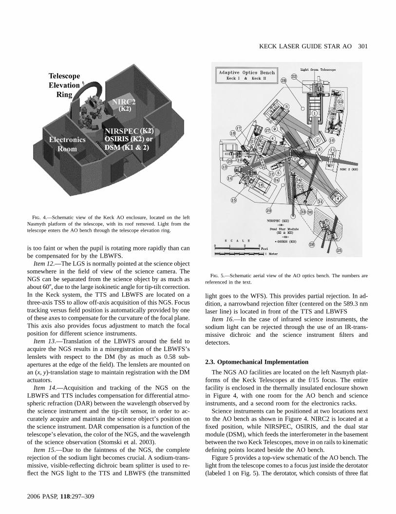
Fig. 4.—Schematic view of the Keck AO enclosure, located on the leftNasmyth platform of the telescope, with its roof removed. Light from thetelescope enters the AO bench through the telescope elevation ring.
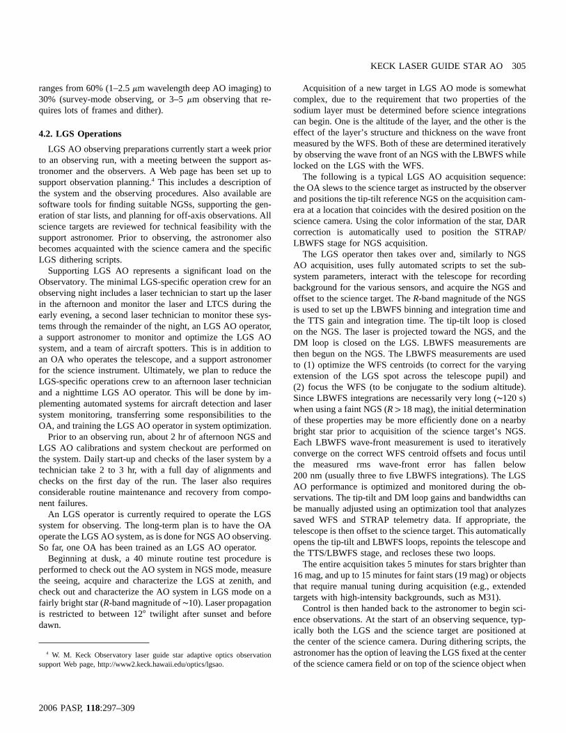
Fig. 5.—Schematic aerial view of the AO optics bench. The numbers arereferenced in the text.
is too faint or when the pupil is rotating more rapidly than canbe compensated for by the LBWFS.
Item 12.—The LGS is normally pointed at the science objectsomewhere in the field of view of the science camera. TheNGS can be separated from the science object by as much asabout 60�, due to the large isokinetic angle for tip-tilt correction.In the Keck system, the TTS and LBWFS are located on athree-axis TSS to allow off-axis acquisition of this NGS. Focustracking versus field position is automatically provided by oneof these axes to compensate for the curvature of the focal plane.This axis also provides focus adjustment to match the focalposition for different science instruments.
Item 13.—Translation of the LBWFS around the field toacquire the NGS results in a misregistration of the LBWFS’slenslets with respect to the DM (by as much as 0.58 sub-apertures at the edge of the field). The lenslets are mounted onan (x, y)-translation stage to maintain registration with the DMactuators.
Item 14.—Acquisition and tracking of the NGS on theLBWFS and TTS includes compensation for differential atmo-spheric refraction (DAR) between the wavelength observed bythe science instrument and the tip-tilt sensor, in order to ac-curately acquire and maintain the science object’s position onthe science instrument. DAR compensation is a function of thetelescope’s elevation, the color of the NGS, and the wavelengthof the science observation (Stomski et al. 2003).
Item 15.—Due to the faintness of the NGS, the completerejection of the sodium light becomes crucial. A sodium-trans-missive, visible-reflecting dichroic beam splitter is used to re-flect the NGS light to the TTS and LBWFS (the transmitted
light goes to the WFS). This provides partial rejection. In ad-dition, a narrowband rejection filter (centered on the 589.3 nmlaser line) is located in front of the TTS and LBWFS
Item 16.—In the case of infrared science instruments, thesodium light can be rejected through the use of an IR-trans-missive dichroic and the science instrument filters anddetectors.
2.3. Optomechanical Implementation
The NGS AO facilities are located on the left Nasmyth plat-forms of the Keck Telescopes at the f/15 focus. The entirefacility is enclosed in the thermally insulated enclosure shownin Figure 4, with one room for the AO bench and scienceinstruments, and a second room for the electronics racks.
Science instruments can be positioned at two locations nextto the AO bench as shown in Figure 4. NIRC2 is located at afixed position, while NIRSPEC, OSIRIS, and the dual starmodule (DSM), which feeds the interferometer in the basementbetween the two Keck Telescopes, move in on rails to kinematicdefining points located beside the AO bench.
Figure 5 provides a top-view schematic of the AO bench. Thelight from the telescope comes to a focus just inside the derotator(labeled 1 on Fig. 5). The derotator, which consists of three flat

302 WIZINOWICH ET AL.
2006 PASP,118:297–309
Fig. 6.—CAD drawing of the STRAP tip-tilt sensor and LBWFS.
Fig. 7.—Schematic of the location of the laser equipment room on the domefloor, the dye laser table, and the projection telescope (beam tube and launchlens), and the IR boresight camera on the side of the telescope.
mirrors, can be used to keep either the image or the pupil fixed.The next element (2) is a fast tip-tilt mirror consisting of a203 mm diameter silicon carbide mirror with three piezoelectricactuators. The beam continues to diverge to an off-axis parabola(3) that collimates the light and reimages the primary mirror ofthe telescope onto the DM (4). The Xinetics, Inc., DM has 349electrostrictive actuators on a 7 mm spacing, corresponding to56 cm spacing on the primary mirror. The second off-axisparabola (6) reconverges the light with the same focal ratio andexit pupil location as initially provided by the telescope. Thelight is split at a visible-reflecting, IR-transmitting dichroic (7).The infrared light (11 mm wavelength) proceeds either directlyto NIRC2 or off a fold mirror (9) to OSIRIS, or off anotherfold mirror (10) to NIRSPEC. Since NIRSPEC was designedas a seeing-limited instrument, a set of reflective reimagingoptics (30–34) was implemented to provide a factor of 10magnification to take advantage of the increased angular res-olution behind AO while maintaining the pupil and imageposition within NIRSPEC. The light to the DSM that feedsthe interferometer is picked off in collimated space by an IR-reflective, visible-transmitting dichroic (5).
The visible-reflecting dichroic (7) sends the visible light to-ward the various wave-front sensors. A translation stage (13)allows the selection of either a 4% reflective beam splitter forNGS mode or a visible-reflecting, sodium-transmitting dichroicfor LGS mode. The transmitted light proceeds to a pair of field-steering mirrors (14), which select an object within the availablefield of view (up to 40� off-axis) and direct it down the axisof the Shack-Hartman wave-front sensor optics (15) and camera(16). These optics consist of a field stop, transmissive opticsthat reimage the DM onto an array of 200mm square lenslets,and transmissive optics that relay and demagnify the imagesfrom the lenslets onto the Adaptive Optics Associates camera.
The MIT/LL CCD consists of 64# 64, 21mm square pixels.The image from each lenslet is reimaged onto 2# 2 pixels,with 1 pixel between subapertures. The entire WFS assembly,from the field stop to the camera, is mounted on a translationstage to maintain conjugation to the sodium layer.
A translation stage (18) allows a mirror to be inserted tofeed the light toward the 2� diameter field of view of the ac-quisition camera (21). In LGS mode, this mirror is translatedout of the beam, and the NGS light is sent to the LBWFS (19)and the TTS (20), mounted on an (x, y, z)-translation stage, asshown in Figure 6. STRAP is a quadrant avalanche photodiodeunit manufactured by Microgate. The light to STRAP is colli-mated through a filter wheel and then reimaged at a slower focalratio (f/37.5) onto the quad lenslet of STRAP. After reflectionoff an 80 : 20 beam splitter, light heading toward the LBWFSgoes through a lens and field stop mounted in a lens-tube as-sembly. The light is then collimated before passing through alenslet array mounted on an (x, y) motorized stage. The lensletsare imaged on a Photometrics 512# 512 CCD detector. TheLBWFS lenslets are registered to the DM actuators in a patternidentical to the WFS lenslets, but with 16# 16 pixels persubaperture instead of 2# 2 pixels.
3. LASER GUIDE STAR
3.1. Laser System
A schematic of the laser system location is shown in Fig-ure 7. A thermally insulated laser room on the dome floorhouses six flash-lamp–pumped, frequency-doubled Nd-YAGlasers and a dye master oscillator (DMO), plus associatedhardware and safety systems. The DMO is narrowly tuned tothe center of the sodium doublet wavelength. The DMO’soutput is broadened across the doublet with a pair of electro-optic phase modulators and then coupled into a single-mode

KECK LASER GUIDE STAR AO 303
2006 PASP,118:297–309
fiber. The single-mode fiber provides the seed light to a tableon the side of the telescope, where it passes through two stagesof dye amplification (preamplifier and amplifier stages). TheYAG lasers, coupled through multimode fibers, are used topump the various dye laser and amplification stages. Theselasers areQ-switched at either 13 or 26 kHz, with pulse du-rations of 150 ns, and each produces about 40 W of outputpower. The 26 kHz versions are used to pump the DMO andpreamplifier. The four 13 kHz versions, two of which are timedelayed to produce an overall 26 kHz pulse rate, are used topump the amplifier.
A 1.2 # 1.8 m laser table, shown in Figure 8, is locatedvertically in an enclosure on the elevation ring of the telescope.In addition to the two stages of dye amplifiers, a significantnumber of transport and formatting optics, and the first elementof the projection telescope, this table contains several alignmentand diagnostic tools. These tools include power meters, apower-in-the-bucket camera, and pointing and centering cam-eras. The last element on the laser table is a pointing mirrorthat is used to center the laser with respect to the science objectand to compensate for tilt changes due to flexure and the dis-tance to the sodium layer (Summers et al. 2004).
The final output of the dye laser is sent to the sky througha projection telescope with a 50 cm diameter output lens,mounted to the side of the telescope. Both the laser table andthe projection telescope move with the telescope in azimuthand elevation. An extensive programmable logic control safetysystem is in place to protect personnel and the laser itself.
The major weak point of the current laser system is its overallcomplexity (nine lasers in total). Failure points include theYAGs, especially the use of flash lamps, and the inherent dif-ficulties of dye lasers, including many dye-cell burns in ourearly days. The wall-plug efficiency is also low, with∼50 kWproducing∼12 W of output power. Sodium-wavelength solid-state lasers, which were unavailable when we started this pro-ject, are much less complex and should be far more efficientand reliable.
3.2. Laser Operation and Coordination
Safety systems are in place to protect aircraft and satellites.Our Federal Aviation Administration–approved approach toaircraft safety is to have two spotters outside during all laseroperations, with switches to shutter the laser. We also have anIR camera boresighted to the laser that will automatically shut-ter the laser in the event of aircraft detection. Given Hawaii’slocation in the middle of the Pacific, we have only had to shutterthe laser for an aircraft a couple of times. Our longer termplans include the implementation of a visible wide-field camerasystem for aircraft detection, and possibly the use of a Hawaii-wide radar feed to alleviate the need for spotters.
Prior to each laser observing run, a list of targets and theirobservation times is faxed to the Laser Clearinghouse at theUS Space Control Center. The Space Control Center faxes back
a list of any required blackout periods, to avoid illuminatingsatellites. This has had minimal impact on our nighttime op-erations to date, since blackout periods have been rare, but itrequires careful preobserving planning.
A laser traffic control system (LTCS) is also in place toensure that the laser does not contaminate the observations ofother telescopes (Summers et al. 2003). All the potentiallyaffected telescopes on Mauna Kea provide their current point-ing coordinates to the LTCS via a URL, along with additionalparameters such as field of view, and the laser is automaticallyshuttered by the LTCS when the laser passes through their fieldof view. The surface brightness of the Keck laser measured bythe Subaru Telescope at elevation angles between 45� and 60�was found to be relatively low, roughly equivalent to 19.5 magarcsec�2; however, the impact could be significant if the inter-section were to occur near the LGS itself (Hayano et al. 2003).
See Wizinowich et al. (1998) for a discussion of the coor-dination and use of laser beacons on Mauna Kea.
3.3. Laser Guide Star
The performance of the LGS AO system depends on thepower and beam quality of the laser and the density and struc-ture of the sodium layer. The laser is typically operated at anoutput power of between 12 and 14 W. Depending on thesodium density, this generates an LGS with an equivalentVmagnitude of typically 9.5 to 10.5 mag at the zenith (or∼140to 55 photons s�1 cm�2). The return decreases with zenith angle,due to the resulting increase in the distance to the sodium layerand the amount of Rayleigh scatter.
The FWHM of the LGS image as seen by the subaperturesclosest to the laser launch telescope is typically 1�.0 to 1�.4. Asseen in Figure 3, the images appear elongated as the sub-apertures become farther away from the launch telescope. Thiselongation has been observed to be 3�.4 FWHM for a sodiumlayer thickness of approximately 15 km. A fairly commonlyobserved structure for the sodium layer versus altitude can alsobe seen in the right panel of Figure 3.
4. OBSERVING OPERATIONS
4.1. NGS Operations
During NGS science operations, the astronomer operates thescience instrument from the remote operations room at KeckObservatory’s headquarters, and the observing assistant (OA)operates the AO system from the telescope control room onMauna Kea. The daytime AO calibrations take less than 30minutes and include calibrating the DM-to-lenslet registrationand the non–common-path aberrations between the science in-strument and the WFS optical paths. These are performed bya support astronomer using a set of calibration tools. A morethorough set of AO calibrations (WFS lenslet centering, tele-scope pointing origins, and image sharpening on the scienceinstrument) is performed by an AO expert prior to the firstnight of an observing run.

304 WIZINOWICH ET AL.
2006 PASP,118:297–309
Fig. 8.—Schematic view of the 1.2# 1.8 m laser table and the trombone assembly mounted on the elevation ring of the telescope. The dark solid line showsthe optical path from the laser amplifier cell off of the centering mirror, UTT mirror, and pointing mirror, through a three-mirror trombone assembly to the outputup the beam tube. A portion of the light is split off at or near the pointing mirror to several diagnostics cameras. The light path prior to the amplifier begins atthe fiber launch (a single-mode fiber from the dye master oscillator on the dome floor) and passes through the preamplifier and various formatting optics.
At dusk, the OA brings up the AO observing tools and runsa script that automatically configures the AO system for thespecific science instrument and telescope (Keck I or II). TheOA also acquires each new target before turning over controlto the astronomer. The automated tools perform the AO ac-quisition using theV and magnitudes for the NGS pro-B � Vvided by the astronomer’s star list. The DAR-compensationtool positions the science object at the desired location on thescience instrument by compensating for DAR with the field-steering mirrors (FSMs) that feed the WFS. The autosettingtool commands the AO subsystems and the telescope to obtainsky backgrounds and set the WFS frame rate, the tip-tilt andDM gains, and if necessary (for bright objects), the cameragain and WFS neutral density filters; it iterates once, if appro-priate, using the photon flux measured by the WFS to find theoptimal settings. The OA monitors the status and health of theAO system with dedicated tools that also automatically recoverfrom faults. After slewing to a new target, AO acquisition takesbetween 30 and 90 s, depending on the object brightness andthe sky transparency conditions.
Once the AO acquisition is complete, the astronomer selectsthe science instrument configuration, including the rotator modeand position angle, and then controls the observing sequenceusing the science instrument user interfaces. Many possibledithering scripts that are common to near-infrared imaging andspectroscopic observations are commanded from the scienceinstrument user interface. A handshake protocol is used to au-tomatically coordinate the telescope and AO system duringthese dithers. This includes opening the AO loops, repointingthe telescope and FSMs, and closing the AO loops.
The main observing-time overheads in NGS AO observingare telescope slew, telescope fine-acquisition on target (!2 min-utes), AO acquisition (90 s), and AO/telescope/instrumenthandshaking during dither (8–10 s per dither command). Whenusing NIRC2, the NIRC2 setup (20 s for filter/camera moves)and readout (∼8 s frame�1) times also impact observing effi-ciency. Some specific observing modes, such as coronagraphyand spectroscopy, require more setup time to center the targetwith a 10 mas accuracy behind the focal mask or on the spec-troscopic slit. The observing efficiency throughout an AO night
KECK LASER GUIDE STAR AO 305
2006 PASP,118:297–309
ranges from 60% (1–2.5mm wavelength deep AO imaging) to30% (survey-mode observing, or 3–5mm observing that re-quires lots of frames and dither).
4.2. LGS Operations
LGS AO observing preparations currently start a week priorto an observing run, with a meeting between the support as-tronomer and the observers. A Web page has been set up tosupport observation planning.4 This includes a description ofthe system and the observing procedures. Also available aresoftware tools for finding suitable NGSs, supporting the gen-eration of star lists, and planning for off-axis observations. Allscience targets are reviewed for technical feasibility with thesupport astronomer. Prior to observing, the astronomer alsobecomes acquainted with the science camera and the specificLGS dithering scripts.
Supporting LGS AO represents a significant load on theObservatory. The minimal LGS-specific operation crew for anobserving night includes a laser technician to start up the laserin the afternoon and monitor the laser and LTCS during theearly evening, a second laser technician to monitor these sys-tems through the remainder of the night, an LGS AO operator,a support astronomer to monitor and optimize the LGS AOsystem, and a team of aircraft spotters. This is in addition toan OA who operates the telescope, and a support astronomerfor the science instrument. Ultimately, we plan to reduce theLGS-specific operations crew to an afternoon laser technicianand a nighttime LGS AO operator. This will be done by im-plementing automated systems for aircraft detection and lasersystem monitoring, transferring some responsibilities to theOA, and training the LGS AO operator in system optimization.
Prior to an observing run, about 2 hr of afternoon NGS andLGS AO calibrations and system checkout are performed onthe system. Daily start-up and checks of the laser system by atechnician take 2 to 3 hr, with a full day of alignments andchecks on the first day of the run. The laser also requiresconsiderable routine maintenance and recovery from compo-nent failures.
An LGS operator is currently required to operate the LGSsystem for observing. The long-term plan is to have the OAoperate the LGS AO system, as is done for NGS AO observing.So far, one OA has been trained as an LGS AO operator.
Beginning at dusk, a 40 minute routine test procedure isperformed to check out the AO system in NGS mode, measurethe seeing, acquire and characterize the LGS at zenith, andcheck out and characterize the AO system in LGS mode on afairly bright star (R-band magnitude of∼10). Laser propagationis restricted to between 12� twilight after sunset and beforedawn.
4 W. M. Keck Observatory laser guide star adaptive optics observationsupport Web page, http://www2.keck.hawaii.edu/optics/lgsao.
Acquisition of a new target in LGS AO mode is somewhatcomplex, due to the requirement that two properties of thesodium layer must be determined before science integrationscan begin. One is the altitude of the layer, and the other is theeffect of the layer’s structure and thickness on the wave frontmeasured by the WFS. Both of these are determined iterativelyby observing the wave front of an NGS with the LBWFS whilelocked on the LGS with the WFS.
The following is a typical LGS AO acquisition sequence:the OA slews to the science target as instructed by the observerand positions the tip-tilt reference NGS on the acquisition cam-era at a location that coincides with the desired position on thescience camera. Using the color information of the star, DARcorrection is automatically used to position the STRAP/LBWFS stage for NGS acquisition.
The LGS operator then takes over and, similarly to NGSAO acquisition, uses fully automated scripts to set the sub-system parameters, interact with the telescope for recordingbackground for the various sensors, and acquire the NGS andoffset to the science target. TheR-band magnitude of the NGSis used to set up the LBWFS binning and integration time andthe TTS gain and integration time. The tip-tilt loop is closedon the NGS. The laser is projected toward the NGS, and theDM loop is closed on the LGS. LBWFS measurements arethen begun on the NGS. The LBWFS measurements are usedto (1) optimize the WFS centroids (to correct for the varyingextension of the LGS spot across the telescope pupil) and(2) focus the WFS (to be conjugate to the sodium altitude).Since LBWFS integrations are necessarily very long (∼120 s)when using a faint NGS (R 1 18 mag), the initial determinationof these properties may be more efficiently done on a nearbybright star prior to acquisition of the science target’s NGS.Each LBWFS wave-front measurement is used to iterativelyconverge on the correct WFS centroid offsets and focus untilthe measured rms wave-front error has fallen below200 nm (usually three to five LBWFS integrations). The LGSAO performance is optimized and monitored during the ob-servations. The tip-tilt and DM loop gains and bandwidths canbe manually adjusted using an optimization tool that analyzessaved WFS and STRAP telemetry data. If appropriate, thetelescope is then offset to the science target. This automaticallyopens the tip-tilt and LBWFS loops, repoints the telescope andthe TTS/LBWFS stage, and recloses these two loops.
The entire acquisition takes 5 minutes for stars brighter than16 mag, and up to 15 minutes for faint stars (19 mag) or objectsthat require manual tuning during acquisition (e.g., extendedtargets with high-intensity backgrounds, such as M31).
Control is then handed back to the astronomer to begin sci-ence observations. At the start of an observing sequence, typ-ically both the LGS and the science target are positioned atthe center of the science camera. During dithering scripts, theastronomer has the option of leaving the LGS fixed at the centerof the science camera field or on top of the science object when
306 WIZINOWICH ET AL.
2006 PASP,118:297–309
TABLE 1LGS AO Observing Overheads
Action Time
AO setup and laser acquisition (from 12� twilight) . . . . . . . . . . . 30 minutesAcquisition of new target (TT ref. ). . . . . . . . . . . . . . . . . .R ! 15.5 5 minutesAcquisition of new target (TT ref. ). . . . . . . . . .15.5! R ! 19.0 10 minutesDither with laser move. . . . . . . . . . . . . . . . . . . . . . . . . . . . . . . . . . . . . . . . . 20 sDither without laser move. . . . . . . . . . . . . . . . . . . . . . . . . . . . . . . . . . . . . 7 sRecovery from aircraft or LTCS shuttering of the laser. . . . . . 2 minutes
Note.—These numbers reflect performance as of 2005 July.
the science object is repositioned on the science instrument. Inthe latter case, if the DM loop is initially closed, then repointingthe telescope will automatically open the DM and uplink tip-tilt loops, reposition the laser pointing mirror and the WFSFSMs, and reclose the loops. If the TTS loop is closed, thenrepointing the telescope will always open the TTS and LBWFSloops, reposition the STRAP/LBWFS stage to reacquire theNGS with DAR corrections, and reclose these loops.
5. THE SCIENCE FACILITY
5.1. NGS Science Capability
The performance of the Keck II NGS AO system is reportedin van Dam et al. (2004). The achieved on-axisH-band Strehlratio varies from 0.4 for stars brighter than to 0.1 forV p 9
. NGSs can be used as far off-axis as 40�.V p 14Keck NGS AO science output has included the publication
of 74 refereed science papers as of 2005 October, includingseven papers with the interferometer. Keck Observatory staffmaintain a bibliography of refereed Keck AO science papers.5
The mix of these papers is 31% planetary, 54% Galactic, and15% extragalactic. Solar system science has included obser-vations of planets, especially Neptune and Uranus, moons ofplanets such as Io and Titan, and asteroids. One feature thathas made the Keck II system especially suitable for planetaryscience is that the WFS can close on objects as large as 4� indiameter. Galactic science has included companion searchesand orbits, circumstellar disks, pre–planetary nebulae, and as-trometric and spectroscopic measurements of the stars orbitingthe black hole at the center of our Galaxy. Extragalactic sciencehas been limited to faint galaxies near bright stars and galaxieswith bright cores, a limitation that has been dramatically re-duced with LGS AO.
5.2. LGS Science
5.2.1. Science Demonstration Program
An LGS engineering science program was implemented totest and demonstrate the most challenging observing modes ina realistic way, and to provide an opportunity for early scientificuse of the system. Projects spanning planetary, Galactic, andextragalactic astronomy were proposed by members of theKeck user community, and the observations were performedby the Keck AO engineering team during commissioningnights.
Initial engineering science projects included observations ofthe HK Tau binary disk system during our first closed-loopdemonstration in 2003 September, and observations of the Eggpre–planetary nebula in 2004 June (Bouchez et al. 2004). Theangular resolutions of the Egg Nebula images are 3 to 4 times
5 W. M. Keck Observatory astronomical science with adaptive optics bib-liography, http://www2.keck.hawaii.edu/library/biblios/aokeck.php.
higher than that achieved with NICMOS on theHubble SpaceTelescope.
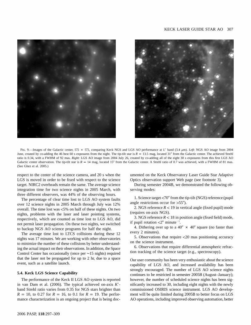
The Galactic center was observed for 1.5 hr inK� andL�in 2004 July for the primary purpose of comparing LGS AOperformance to previous NGS AO data (Ghez et al. 2005).The improvement in performance was dramatic, as shownin Figure 9. In addition, an 80� # 80� wide-field mosaic inHe i and H2 (1–0) of the region surrounding the Galacticcenter was also acquired on the same night, in a total ob-serving time of 0.3 hr. These images have provided an ex-cellent demonstration of the wide-field capabilities of the LGSAO system. Since the laser can remain at the center of eachelement of the mosaic, and the isokinetic angle for the tip-tilt star is large, the image quality remains essentially constantover the entire field.
Observations of the CATS (Center for Adaptive Optics Trea-sury Survey) fields were proposed to compare LGS and NGSperformance on faint extragalactic targets, and to target par-ticularly interesting galaxies (Chandra sources and high-red-shift candidates) in previously inaccessible CATS fields. A fieldnear guide star GOODS-S19 was observed for 3 hr in 2004October. The resulting images of merging galaxies have beenpublished in Melbourne et al. (2005).
Solar system engineering science projects have included mea-suring the system mass of binary Trojan asteroids (Marchis etal. 2005) and Kuiper Belt objects (Brown et al. 2005). Additionalprojects have included a search for brown dwarf binaries, andimages of the Andromeda galaxy shown in Figure 10.
5.2.2. Shared-Risk Science Programs
A restricted number of LGS AO shared-risk science nightswith NIRC2 (12) were awarded by the Keck time allocationcommittees in semester 2005A (February–August), while de-velopment continued on the LGS system. As of 2005 October,six refereed papers had been accepted for publication (Gal-Yam et al. 2005; Liu et al. 2005; see also papers cited in§ 5.2.1).
5.3. LGS Science Observing Efficiency
The observing time overheads associated with LGS AO aresummarized in Table 1. The AO/telescope/instrument hand-shake during dithers takes 7 s when the LGS is fixed with
KECK LASER GUIDE STAR AO 307
2006 PASP,118:297–309
Fig. 9.—Images of the Galactic center, 5�.5 # 5�.5, comparing Keck NGS and LGS AO performance atL� band (3.4mm). Left: NGS AO image from 2004June, created by co-adding the 46 best 60 s exposures from the night. The tip-tilt star is mag, located 31� from the Galactic center. The achieved StrehlR p 13.5ratio is 0.34, with a FWHM of 92 mas.Right: LGS AO image from 2004 July 26, created by co-adding all of the eight 30 s exposures from this first LGS AOGalactic center observation. The tip-tilt star is mag, located 15� from the Galactic center. A Strehl ratio of 0.7 was achieved, with a FWHM of 81 mas.R p 14(See Ghez et al. 2005.)
respect to the center of the science camera, and 20 s when theLGS is moved in order to be fixed with respect to the sciencetarget. NIRC2 overheads remain the same. The average scienceintegration time for two science nights in 2005 March, withthree different observers, was 44% of the observing hours.
The percentage of clear time lost to LGS AO system faultsover 12 science nights in 2005 March through July was 12%overall. The time lost was!5% on half of these nights. On twonights, problems with the laser and laser pointing systems,respectively, which are counted as time lost to LGS AO, didnot permit laser propagation. On these two nights, we switchedto backup NGS AO science programs for half the night.
The average time lost to LTCS collisions during these 12nights was 17 minutes. We are working with other observatoriesto minimize the number of these collisions by better understand-ing the actual impact on their observations. In addition, the SpaceControl Center has occasionally (once per∼15 nights) requiredthat the laser not be propagated for up to 2 hr, due to a spaceevent, such as a satellite launch.
5.4. Keck LGS Science Capability
The performance of the Keck II LGS AO system is reportedin van Dam et al. (2006). The typical achieved on-axisK�-band Strehl ratio varies from 0.35 for NGS stars brighter than
, to 0.27 for , to 0.1 for . The perfor-R p 10 R p 16 R p 19mance characterization is an ongoing project that is being doc-
umented on the Keck Observatory Laser Guide Star AdaptiveOptics observation support Web page (see footnote 3).
During semester 2004B, we demonstrated the following ob-serving modes:
1. Science target!70� from the tip-tilt (NGS) reference (pupilangle restrictions occur for155�).
2. NGS reference in vertical angle (fixed pupil) modeR ! 19(requires on-axis NGS).
3. NGS reference in position angle (fixed field) mode,R ! 18if pupil rotation !2� minute�1.
4. Dithering over up to a 40� # 40� square (no faster thanevery 2 minutes).
5. Observations that require!20 mas positioning accuracyon the science instrument.
6. Observations that require differential atmospheric refrac-tion tracking of the science target (e.g., spectroscopy).
Our user community has been very enthusiastic about the sciencecapability of LGS AO, and increased availability has beenstrongly encouraged. The number of LGS AO science nightscontinues to be restricted in semester 2005B (August–January);however, the number of scheduled science nights has been sig-nificantly increased to 30, including eight nights with the newlycommissioned OSIRIS science instrument. LGS AO develop-ment will be quite limited during 2005B to better focus on LGSAO operations, including improved observing automation, better

308 WIZINOWICH ET AL.
2006 PASP,118:297–309
Fig. 10.—A 10� # 10� image of the core of the Andromeda galaxy imagedat K� (2.1 mm). A compact cluster 55� away was used as the tip-tilt reference.The dynamical center of the galaxy, the likely location of a supermassive blackhole, is located∼1� to the lower right of the highest density region. Individualgiant stars are clearly resolved throughout the image.
management and maintenance of the laser and AO systems, moretraining for the observing support group, and completion of theLGS AO performance characterization effort.
6. CONCLUSION
We have described the approach taken in the implementationof a laser guide star system on the Keck II system, as well asthe early scientific capabilities. An impressive amount of sci-ence has already been achieved with the AO facilities describedin this paper, and the future for high angular resolution as-tronomy at the W. M. Keck Observatory looks extremelypromising.
This future includes further improvements to the Keck IILGS AO system, upgrades to the real-time wave-front pro-cessor system and wave-front sensor cameras, the implemen-tation of a commercial solid-state laser on the Keck I Telescope,
along with laser projection from behind the secondary mirror,and potentially a next-generation LGS AO system.
Financial support for the development and fabrication of theKeck II LGS AO system was generously provided by theW. M. Keck Foundation. This material is based on work sup-ported in part by the National Science Foundation Science andTechnology Center for Adaptive Optics, managed by the Uni-versity of California at Santa Cruz under agreement AST 98-76783, and based on work supported in part under the auspicesof the US Department of Energy, National Nuclear SecurityAdministration, by the University of California, Lawrence Liv-ermore National Laboratory, under contract W-7405-Eng-48.Any opinions, findings, and conclusions or recommendationsexpressed in this material are those of the authors and do notnecessarily reflect the views of the National Science Foundationor the US Department of Energy.
The author list reflects those people directly involved in theimplementation of the LGS AO system. Many individuals havecontributed to the development and implementation of the KeckAO systems and laser over the years, including S. Acton,J. An, K. Avicola, J. Bell, J. Brase, F. Chaffee, J. Chock,L. Chock, R. Cohen, A. Conrad, G. Erbert, H. Friedman,J. Gathright, D. Gavel, A. Gleckler, P. Goude, T. Gregory,M. Hess, K. Ho, H. Jones, K. Kinoshita, T. Kuklo, O. Lai,W. Lupton, I. Lynn, B. Macintosh, J. Maute, C. Melcher,D. McBride, D. Medeiros, R. Mouser, C. Nance, C. Neyman,S. Olivier, T. Saloga, C. Shelton, M. Sirota, R. Sumner,K. Sweeney, K. Waltjen, J. Watson, T. Williams, N. Wong, andthe entire support staff of the W. M. Keck Observatory. Wewould also like to express our appreciation to past and presentmembers of our review committees and AO working groups:E. Becklin, M. Brown, G. Chanan, R. Dekany, P. Everett,R. Fugate, A. Ghez, B. Kibrick, S. Kulkarni, J. Larkin, M. Liu,T. Mast, K. Matthews, J. Nelson, D. Sandler, and M. Troy.
The data presented herein were obtained at the W. M. KeckObservatory, which is operated as a scientific partnershipamong the California Institute of Technology, the Universityof California, and the National Aeronautics and Space Ad-ministration. The Observatory was made possible by the gen-erous financial support of the W. M. Keck Foundation. Theauthors wish to recognize and acknowledge the significant cul-tural role and reverence that the summit of Mauna Kea hasalways had within the Hawaiian community. We are most for-tunate to have the opportunity to conduct observations fromthis mountain.
REFERENCES
Bouchez, A. H., et al. 2004, Proc. SPIE, 5490, 321Brown, M. E., et al. 2005, ApJ, 632, L45Colavita, M. M., Wizinowich, P. L., & Akeson, R. L. 2004, Proc.
SPIE, 5491, 454Foy, R., & Labeyrie, A., 1985, A&A, 152, L29Friedman, H. W., et al. 1998, Proc. SPIE, 3353, 260Gal-Yam, A., et al. 2005, ApJ, 630, L29
Ghez, A. M., et al. 2005, ApJ, 635, 1087Graves, J. E., Roddier, F., Northcott, M., Anuskiewicz, J., & Monnet,
G. 1994, Proc. SPIE, 2201, 502Hackenberg, W., et al. 2000, A&A, 363, 41Hayano, Y., et al. 2003, PASP, 115, 1419Larkin, J., et al. 2003, Proc. SPIE, 4841, 1600Liu, M. C., et al. 2005, ApJ, 634, 616

KECK LASER GUIDE STAR AO 309
2006 PASP,118:297–309
Marchis, F., Descamps, P., Hestroffer, D., & Berthier, J. 2005, Nature,436, 822
Max, C., et al. 1997, Science, 277, 1649McCullough, P. R., et al. 1995, ApJ, 438, 394McLean, I. S., et al. 1998, Proc. SPIE, 3354, 566Melbourne, J., et al. 2005, ApJ, 625, L27Perrin, M. D., et al. 2004, Science, 303, 1345Rigaut, F., et al. 1998, PASP, 110, 152Rousset, G., et al. 1994, Proc. SPIE, 2201, 1088Stomski, P., Le Mignant, D., Wizinowich, P., Campbell, R., & Good-
rich, R. 2003, Proc. SPIE, 4839, 943
Stomski, P. J., & Shelton, J. C. 2000, Proc. SPIE, 4007, 608Summers, D., et al. 2003, Proc. SPIE, 4839, 440———. 2004, Proc. SPIE, 5490, 1117Thompson, L., & Gardner, C. 1987, Nature, 328, 229van Dam, M., Le Mignant, D., & Macintosh, B. 2004, Appl. Opt.,
43, 5458van Dam, M., et al. 2006, PASP, 118, 310Wizinowich, P., Simons, D., Takami, H., Veillet, C., & Wainscoat, R.
1998, Proc. SPIE, 3353, 290Wizinowich, P., et al. 2000a, PASP, 112, 315———. 2000b, Proc. SPIE, 4007, 2