the west bengal power development corporation ltd. bharat
TRANSCRIPT


The West Bengal Power Development Corporation Ltd. Bharat Heavy Electricals Ltd.
1X660 MW,SAGARDIGHI THERMAL POWER EXTENSION PROJECT (UNIT #5)- 400KV Switchyard,
Doc. No. TB-SPEC-CB-445-01, Rev. No.-0, 400kV CB
Section 1 : Page 1 of 9
SECTION 1
SCOPE, SPECIFIC TECHNICAL REQUIREMENTS AND QUANTITIES
1.1 SCOPE
This technical specification covers the requirements of design, manufacture, testing at works, packing and dispatch of Circuit Breakers complete with accessories as listed under this specification.
This section covers the specific technical requirements of Circuit Breakers. This constitutes minimum technical parameters for the above item as specified by the customer (WBPDCL). The offered equipment shall also comply with the General Technical Requirements for the project as detailed under section-3 of this specification. The specification comprises of following sections: Section-1: Scope, specific technical requirements and Bill of Quantities Section-2: Equipment specification under scope of supplies. Section-3: General technical requirements for all equipments under the project. Section-4: Guaranteed Technical Particular Section-5: Check List and schedule of technical deviations In case of any conflict between various sections, order of precedence shall be in the same order as listed above. The equipment is required for the following project:
Name of customer : The West Bengal Power Development Corporation Ltd.
Name of Consultant : Development Consultants Private Ltd. Kolkata
Name of the project : 1X660MW thermal power extension project Unit-5 at Sagardighi- 400KV Switchyard.
1.2 SPECIFIC TECHNICAL REQUIREMENTS
TECHNICAL PARAMETERS
Rated voltage kV (rms) 420 Standard to be followed IEC-62271-100,60694, IS-12729 Rated frequency (Hz) 50 No.of poles 3 Design ambient Temperature (deg. C) 50 Rated insulation levels- Class
a. Mechanical endurance class b. Electrical endurance class c. Restrike probability class
----M1---- ----E1---- ----C1----
1.Full wave impulse withstand voltage (1.2/50 micro sec.)
a. between line terminals and ground ± 1425 kVp b. between line terminals and CB open ± 1425 kVp c. across isolating distance ± 1425 kVp impulse on one
terminal and 240kVp power frequency voltage of opposite

The West Bengal Power Development Corporation Ltd. Bharat Heavy Electricals Ltd.
1X660 MW,SAGARDIGHI THERMAL POWER EXTENSION PROJECT (UNIT #5)- 400KV Switchyard,
Doc. No. TB-SPEC-CB-445-01, Rev. No.-0, 400kV CB
Section 1 : Page 2 of 9
polarity on other terminal 2. One minute power frequency dry and wet withstand voltage
a. to earth and between poles 520 kV (rms) b. across isolating distance 610 kVrms
3. Switching impulse withstand voltage (250/2500 micro sec.) dry and wet a. between line terminals and ground ± 1050 kVp b. between line terminals ± 1575 kVp c. across isolating distance 900 kVp impulse on one terminal
and 345kVP power frequency voltage of opposite polarity on other terminal
Maximum radio interference voltage at 320kV rms phase to ground voltage
1000 Micro volt for frequency between 0.5 MHz and 2 MHz for all equipment.
Corona extinction voltage (kVrms) with circuit breaker open or close ‘
320 (min.)
Minimum creepage distance: Phase to ground (mm) 13020 Between CB terminals (mm) 13020 System neutral earthing Effectively Earthed Seismic acceleration 0.1g horizontal( it is coming
under zone –III) Thermal rating of auxiliary contacts 10 A at 220 V DC Breaking capacity of auxiliary contacts constants 2 A DC with circuit time not less
than 20 ms Phase to phase spacing (mm) 7000 Rated continuous current at design Ambient temperature 50C
3150 A
Rated short circuit current Breaking capacity at rated Voltage
50kA (with percentage DC component as per IEC -62271-100 corresponding to Minimum opening time under operating conditions specified)
Symmetrical interrupting capability (kA rms) 50 Rated short time making current(kAp) 125 Rated peak withstand current(kAp) 125 Short time current carrying capability (kArms) 50 for 3 sec. Out of phase breaking current capacity (kArms) 12.5 Out of phase making current capacity (kArms) 50 KA Rated line charging interrupting current at 90 deg. Leading power factor angle
400A (rms)
(The breaker shall be able to interrupt the rated line charging current with a test voltage immediately before opening equal to the product of U/3 and 1.5 as per IEC - 62271-100). Maximum allowable switching over-voltage under any switching condition.
2.3 p.u
Rated small inductive current switching capability with over-voltage less than 2.3pu
0.5 A to 10 A

The West Bengal Power Development Corporation Ltd. Bharat Heavy Electricals Ltd.
1X660 MW,SAGARDIGHI THERMAL POWER EXTENSION PROJECT (UNIT #5)- 400KV Switchyard,
Doc. No. TB-SPEC-CB-445-01, Rev. No.-0, 400kV CB
Section 1 : Page 3 of 9
No. of trip coil 2 per pole No. of closing coil 1 per pole Opening time Not more than 40 miliseconds closing time Not more than 100 milisecond Rated operating duty cycle O-0.3 sec.-CO-3 min-CO Auto Reclosing single phase & three phase auto
reclosing SF6 Gas As per IEC 60376 &61634 Max. difference in the instants of closing / opening of contacts ( ms)
Within a pole 5/2.5ms Between poles 7.5/3.5ms Operating mechanism Spring / Spring Auxiliary voltage for closing coil 220 volt DC (85% -110%)
Auxiliary voltage for tripping coil 220 volt DC (70% -110%)
Auxiliary voltage for spring charge motor/ Heater/Lamp/Sockets
240V±10%, 50 Hz, 1-phase two wire AC supply
Auxiliary voltage for compressor/pump motor 415V ±10%, 50 Hz, 3-phase 3 wire AC,
Heater/lamp/socket 240V, 1ph, 50 Hz.
Auxiliary contacts Each circuit breaker pole shall be provided with an auxiliary switch with a total of twenty independent single pole reversible contacts , exclusively for Owner’s use . The auxiliary switch shall be factory assembled with 10 NO and 10 NC contacts per phase for future use of purchaser.
Noise level at base 140 db max at base of CB
Rated terminal load 200kg static Temperature rise over the design ambient temperature
as per IS/IEC duly adjusted for site condition.
First pole to clear factor 1.3 Number of terminals in common control cabinet all contacts circuits are to be
wired out upto common control cabinet plus 24 terminals exclusively for Owner’s use
Mounting
On Hot dip Galvanised steel structure
Interpole cabling (FRLS) of CB in supplier scope Yes
Terminal connector of CB in supplier scope
NO
Pre insertion resistor Not applicable
Anti pumping Required

The West Bengal Power Development Corporation Ltd. Bharat Heavy Electricals Ltd.
1X660 MW,SAGARDIGHI THERMAL POWER EXTENSION PROJECT (UNIT #5)- 400KV Switchyard,
Doc. No. TB-SPEC-CB-445-01, Rev. No.-0, 400kV CB
Section 1 : Page 4 of 9
1.3 QUANTITIES
S No. Description Quantity Unit
1
Main item- 420 kV, 3150 A, 50 kA for 3 Sec, Three phase SF6 Circuit Breaker without CSD without closing resistor with corona shielding, operating mechanism, Insulators , base frame, HV terminal Plates, control cabinet, support structure, cable glands, ladder (if applicable), marshalling box (if applicable) and other accessories, complete in all respects
2 Nos.
2
Main item- 420 kV, 3150 A, 50 kA for 3 Sec, Three phase SF6 Circuit Breaker without closing resistor with corona shielding, operating mechanism, Insulators , base frame, HV terminal Plates, control cabinet, support structure, cable glands, ladder (if applicable), marshalling box (if applicable) and other accessories, complete in all respects (with provision for CSD).
2 Nos.
3 Main item- Controlled Switching Device (CSD) (for 420kV CB at sl no. 2 above) along with all accessories like transducers etc complete in all respect (except special cables) in all respect.
2 Nos.
4 Main item-Special cables$ for CSD. Length = distance from CB to Relay panel
1000 Meter
5
Main item-Foundation/fixing bolts for 420kV, 3-Phase SF6 Circuit Breaker structure, platform, laddeSr (if applicable) and marshalling box (if applicable) at sl no. 1, 2 and 9. 1Lot = Qty. required for 1 no. 3-Phase 400kV Circuit Breaker.
5 Lot
6 Main item- Portable SF6 gas filling & evacuating equipment as per cl. no. 4.01.05 of section-02
1 No.
7 Main item- Circuit breaker operation analyser as per cl. no. 4.01.05 of section-02
1 No.
8 Main item- Portable SF6 gas leakage detector as per cl. no. 4.01.05 of section-02
2 No.
9
Mandatory spare- 420 kV, 3150 A, 50 kA for 3 Sec, Three phase SF6 Circuit Breaker without CSD without closing resistor with corona shielding, operating mechanism, Insulators , base frame, HV terminal Plates, control cabinet, support structure, cable glands, ladder (if applicable), marshalling box (if applicable) and other accessories, complete in all respects
1 No.
The West Bengal Power Development Corporation Ltd. Bharat Heavy Electricals Ltd.
1X660 MW,SAGARDIGHI THERMAL POWER EXTENSION PROJECT (UNIT #5)- 400KV Switchyard,
Doc. No. TB-SPEC-CB-445-01, Rev. No.-0, 400kV CB
Section 1 : Page 5 of 9
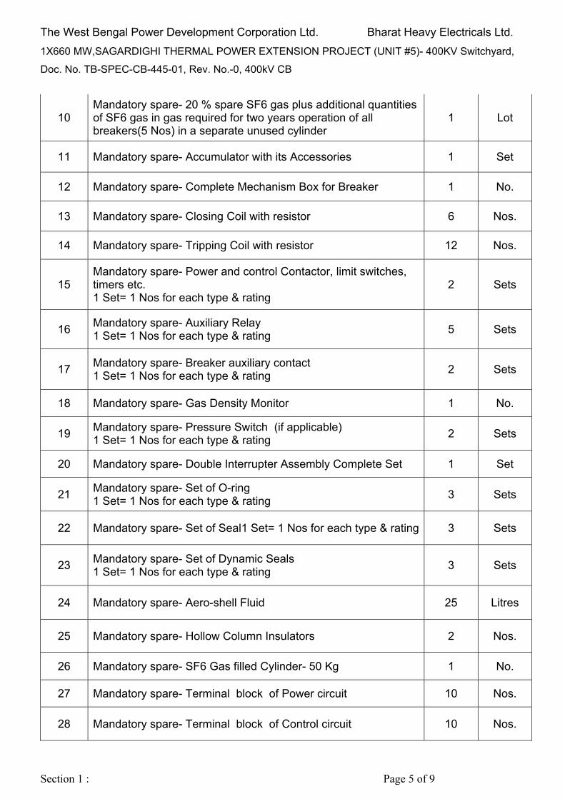
10 Mandatory spare- 20 % spare SF6 gas plus additional quantities of SF6 gas in gas required for two years operation of all breakers(5 Nos) in a separate unused cylinder
1 Lot
11 Mandatory spare- Accumulator with its Accessories 1 Set
12 Mandatory spare- Complete Mechanism Box for Breaker 1 No.
13 Mandatory spare- Closing Coil with resistor 6 Nos.
14 Mandatory spare- Tripping Coil with resistor 12 Nos.
15 Mandatory spare- Power and control Contactor, limit switches, timers etc. 1 Set= 1 Nos for each type & rating
2 Sets
16 Mandatory spare- Auxiliary Relay 1 Set= 1 Nos for each type & rating
5 Sets
17 Mandatory spare- Breaker auxiliary contact 1 Set= 1 Nos for each type & rating
2 Sets
18 Mandatory spare- Gas Density Monitor 1 No.
19 Mandatory spare- Pressure Switch (if applicable) 1 Set= 1 Nos for each type & rating
2 Sets
20 Mandatory spare- Double Interrupter Assembly Complete Set 1 Set
21 Mandatory spare- Set of O-ring 1 Set= 1 Nos for each type & rating
3 Sets
22 Mandatory spare- Set of Seal1 Set= 1 Nos for each type & rating 3 Sets
23 Mandatory spare- Set of Dynamic Seals 1 Set= 1 Nos for each type & rating
3 Sets
24 Mandatory spare- Aero-shell Fluid 25 Litres
25 Mandatory spare- Hollow Column Insulators 2 Nos.
26 Mandatory spare- SF6 Gas filled Cylinder- 50 Kg 1 No.
27 Mandatory spare- Terminal block of Power circuit 10 Nos.
28 Mandatory spare- Terminal block of Control circuit 10 Nos.

The West Bengal Power Development Corporation Ltd. Bharat Heavy Electricals Ltd.
1X660 MW,SAGARDIGHI THERMAL POWER EXTENSION PROJECT (UNIT #5)- 400KV Switchyard,
Doc. No. TB-SPEC-CB-445-01, Rev. No.-0, 400kV CB
Section 1 : Page 6 of 9
29 Mandatory spare- Complete set of Push Button Switch 1 Set= 1 Nos. for each colour and area of application.
2 Sets
30 Mandatory spare- Locable Type Switch 1 Set= 1 Nos for each type & rating
2 Sets
31 Mandatory spare- Selector Switch 1 Set= 1 Nos for each type & rating
2 Sets
32 Mandatory spare- MCCB/MCB/Fuse unit with fuse (AC & DC application) 1 Set= 1 Nos for each type & rating
2 Sets
33
Services- Supervision of Erection, Testing & Commissioning of supplied 420kV, 3-Phase Circuit breakers at site.Testing & commissioning instruments (Time interval meter (timing kit), SF6 gas leakage detector & any other special tools like gas filling adapter etc) shall be brought by supplier and shall be taken back after successful completion of testing and commissioning.
16 Man days
34 Services- Supervision of Erection, Testing & Commissioning of supplied CSD’s at site. (including interface with CB)
8 Man days
35 Services- To and fro charges for Supervision of Erection, Testing & Commissioning of supplied Circuit Breakers & CSD’s at site
2 Visits
$ Special cables other than 1100V LT Power & Control Cables required for CSD shall be in bidder’s scope. Only distance from CB to Relay panel has been provided at Sl no. 5 of BOQ. Total requirement of special cable qty. is to be estimated & supplied by bidder based on number of runs etc. Special cables shall be supplied in single drum length after confirmation from BHEL during detailed engineering stage. Details of Controlled Switching Device (CSD) application for 420 kV Circuit Breakers is as mentioned below:
S No. Substation/
SLD Drg No. Dia CB without PIR
CSD used in switching of -
Main Bay CB Tie Bay CB
1 Sagardighi S/s TB-DG-445-316-E001
425-426-427
without PIR; Trafo. application
without PIR; Trafo. application
NOTE:

The West Bengal Power Development Corporation Ltd. Bharat Heavy Electricals Ltd.
1X660 MW,SAGARDIGHI THERMAL POWER EXTENSION PROJECT (UNIT #5)- 400KV Switchyard,
Doc. No. TB-SPEC-CB-445-01, Rev. No.-0, 400kV CB
Section 1 : Page 7 of 9
1) Total contract value may vary upto ± 10% at contract stage. 2) For item no.2, all wiring necessary for interface of circuit breakers with CSD is deemed to
be included in the scope. 3) Supply of terminal connectors for Circuit Breakers is in BHEL scope. 4) Inter pole cabling between Circuit breaker and common marshalling box shall be Non
Plug in type. 5) Inter pole cable schedule shall be provided by bidder during detailed engineering stage. 6) i. For item at sl no. 33 & 34 of BOQ, no. of man days consumed in Supervision of
erection, testing and commissioning of Circuit Breakers & CSD’s shall be duly certified by BHEL Site-incharge. ii.Visit charges are covered separately under sl no. 35 of BOQ. No other charges shall be paid by BHEL.
iii. The following instruments/kits shall be brought by Bidder and shall be taken back after successful completion of testing and commissioning:
(a) Time Interval meter (Timing kit) (b) SF6 Gas leak Detector (c) Any other special tools like gas filling adapter etc
7) The following instruments/kits shall be provided by BHEL at site:
(a) DCRM (b) 5kV Insulation tester (c) 1kV Insulation tester (d) Single phase variac (e) Dew Point meter (f) Capacitance and Tan Delta Kit (g) Contact Resistance measurement kit (h) Multimeter
Circuit Breaker Analyzer - Adaptor/Transducer for analyzer (if required) suitable for breaker shall be scope of bidder. Any other instrument(s), if required for Testing/commissioning of Circuit Breaker shall be arranged by Circuit Breaker supplier without any price implication to BHEL.
8) Each circuit breaker shall be furnished with fitting and accessories as listed in the Annexure-B clause A1 of section -2 of technical specification
Enclosures:
Sl No
Drg No. Description
1 TB-DG-445-316-E001 Rev01
SLD of 400kV S/s at Sagardighi (WB)

The West Bengal Power Development Corporation Ltd. Bharat Heavy Electricals Ltd.
1X660 MW,SAGARDIGHI THERMAL POWER EXTENSION PROJECT (UNIT #5)- 400KV Switchyard,
Doc. No. TB-SPEC-CB-445-01, Rev. No.-0, 400kV CB
Section 1 : Page 8 of 9
1.5 TESTS
Routine Test
During manufacture and on completion, all equipment, clamps, connectors and accessories shall be subjected to the Routine Tests as laid down in latest revision of IEC/IS.
In addition to above tests specified by IEC/IS, the following tests also have to be carried out for specific equipments :
i) The speed curves for EHV circuit breaker shall with the help of a suitable operation analyser to determine the breaker contact movement during opening, closing, auto-reclosing and trip-free operation under normal as well as limiting operating conditions (Control Voltage, pneumatic pressure etc.)
Type Test
Type tests on circuit breaker shall carried out as stipulated in relevant IEC/Indian Standards. Test certificates for type tests, as stipulated in Indian Standards carried out on similar equipment clamps, connectors etc. shall be furnished.
Following additional type tests reports to be provided for EHV circuit breaker:
i) Short line fault test.
ii) Out of phase making and breaking test as per IEC.
iii)Rated line charging current breaking test. The breaker shall be able to interrupt the line charging current with a test voltage of 1.4 p.u. instead of 1.2 p.u. as per IEC.
iv)Test to demonstrate ability to withstand 2.5 times the rated voltage across the open circuit breaker at & below lockout pressure.
v) Seismic withstand test in unpressurised condition.
Bidder shall submit valid type test reports ( as per relevant IEC/IS standard) for the tests carried out within last five years from the date of bid opening i.e. 18.03.2018. The reports should have been conducted on identical or similar equipment/components to those offered. In case type test reports are more than 5 years old (from the date of bid opening) or the reports of type tests are found to be technically unacceptable, the type test shall be conducted by the bidder without cost and delivery implication to BHEL.
1.6 INSPECTION & TESTING
Before being fitted on the equipment, all components shall be subjected to routine tests at the Contractors factory, as per the relevant IEC/IS standards. A detailed test report proving the successful passing of such tests shall be provided. Prior to dispatch, the routine & acceptance tests shall be carried out on equipment in accordance with the applicable IEC /IS and the material shall be offered for final inspection to BHEL and WBDPCL in accordance with agreed quality plan with 15 days advance information.

The West Bengal Power Development Corporation Ltd. Bharat Heavy Electricals Ltd.
1X660 MW,SAGARDIGHI THERMAL POWER EXTENSION PROJECT (UNIT #5)- 400KV Switchyard,
Doc. No. TB-SPEC-CB-445-01, Rev. No.-0, 400kV CB
Section 1 : Page 9 of 9
All the tests shall be carried out in the presence of the BHEL/WBPDCL representative unless the witnessing of tests is waived beforehand by WBPDCL. The Bidder shall give minimum 15 days advance notice of the date when the tests would be carried out. The Bidder shall obtain approval for the type test procedure before conducting the type test. The procedure shall specify the test set up, instrument to be used, acceptance norms, interval of recording etc. for the type test to be carried out. In case the Bidder has conducted any of the specified type tests on similar equipment within the last five (5) years as on the date of bid opening i.e. 18.03.2018, he may submit type test report during detail engineering for waive of conducting such test. For these tests, only reports are to be submitted. In case the Bidder is not able to submit report of the type test(s) conducted within last five (5) years from the date of bid opening i.e. 18.03.2018 or in the case of type test(s) reports are not found to be meeting to specification requirement, the Bidder shall conduct all such test(s) under this contract without cost and delivery implication to BHEL and submit the reports for approval. For short circuit test, proto-type of similar design and of same capacity with documentary evidence shall be submitted for customer approval. For newly designed equipment, type test shall be conducted at CPRI or Government approved laboratory at the bidder’s cost. Certified reports of all the tests carried out at the works shall be furnished in six (6) sets for approval. The equipment shall be dispatched from works only after receipt of written approval of the test reports and MDCC.
1.7 QUALITY PLAN
The contractor shall carry out contract works in accordance with sound quality management principles which shall include such as controls which are necessary to ensure full compliance to all requirements of the specification & applicable international standards. These quality management requirements shall apply to all activities during design, procurement, manufacturing, inspection, testing, packaging, shipping, inland transportation, storage, site erection & commissioning. Contractor shall submit detailed Quality Plan for BHEL / customer’s approval.

TECHNICAL REQUIREMENTS
FOR CONTROL SWITCHING DEVICE (CSD)
a) The CSD shall be designed to operate correctly and satisfactorily with the excursion of auxiliary A/C
& DC voltages and frequency as specified in section ‐ GTR. b) The CSD shall meet the requirements of
IEC‐61000‐4‐16 class IV for HF disturbance test (for short and long durations both) and fast transient
test shall be as per IEC‐61000‐4‐4 level IV and insulation test as per IEC 60255–5.
c) The CSD shall have functions for switching ON & OFF the circuit breakers.
d) The CSD shall get command to operate the breakers manually. The controller shall be able to
analyze the current and voltage waves available through the signals from secondaries of CTs & CVTs
for the purpose of calculation of optimum moment of the switching the circuit breaker and issue
command to circuit breaker to operate.
e) The CSD shall also have an adaptive control feature to consider the next operating time of the
breaker in calculation of optimum time of issuing the switching command. In calculation of next
operating time of the breaker, the CSD must consider all factors that may affect the operating time of
the breaker such as, but not limited to, ambient temperature, control voltage variation, SF6 gas
density variations etc. Schematic drawing for this purpose shall be provided by the contractor. The
accuracy of the operating time estimation by the controller shall be better than ± 0.5 ms.
f) The CSD should have display facility at the front for the display of settings and measured values.
g) The CSD shall be PC compatible for the setting of various parameters and down loading of the
settings and measured values, date, time of switching etc. Window based software for this purpose
shall be supplied by the contractor to be used on the owner’s PC.
h) The controller shall be suitable for current input of 1 ampere from the secondary of the CTs. and
110 V (Ph to Ph) from the CVTs. The CSD shall withstand transient and dynamic state values of the
current from the secondary of the CTs and CVTs.
i) The CSD shall have time setting resolution of 0.1 ms or better.
j) The CSD shall have sufficient number of output/input potential free contacts for connecting the
monitoring equipment and annunciation system available in the control room. Necessary details shall
be worked out during engineering of the scheme.
k) The CSD shall also record and monitor the switching operations and make adjustments to the
switching instants to optimize the switching behavior as necessary. It shall provide self‐diagnostic
facilities, signaling of alarms and enable downloading of data captured from the switching events.
l) The provision for bypassing the Controlled switching device shall be provided through BCU and
SCADA both so that whenever, the CSD is not healthy due to any reason (including auxiliary supply
failure), uncontrolled trip/close command can be extended to the circuit Breaker. Alternatively, in
case of any non‐operation of the CSD after receiving a close/trip command after a pre‐determined
time delay, the CSD should automatically be bypassed so as to ensure that the trip and close
commands are extended to the Trip/Close coils through subsequent command.
m) The CSD shall be provided with a communication port to facilitate online communication of the
CSD with Substation automation system directly on IEC 61850 protocols. If the CSD does not meet
the protocols of IEC 61850, suitable gateway shall be provided to enable the communication of CSD
as per IEC 61850.

WBPDCLEPC Bid Document
Sagardighi Thermal Power Project 1x660 MW Unit No. 5, Phase - III
Development Consultants Pvt. Ltd. Page 8 of 95 Volume : II-F/1 Section : XIII
400 KV Switchyard
4.00.00 SPECIFIC REQUIREMENTS 4.01.00 Circuit Breaker 4.01.01 Each circuit breaker shall be furnished complete with : i) Fittings and accessories. ii) Auxiliary equipment. iii) First filling of SF6 gas plus 20% spare. The equipment will be used in the switchyard having characteristics as listed
in the Annexures. The equipment will be installed outdoor in a hot, humid and tropical
atmosphere. All equipment, accessories and wiring shall have tropical protection, involving
special treatment of metal and insulation against fungus, insects and corrosion.
4.01.02 Type and Duty The circuit breaker shall be three-pole, sulphur hexafluoride (SF6) type,
having internal isolation without any sequential interlock. The circuit breaker shall be restrike free as per IEC under all duty conditions
and shall be capable of performing their duties without opening resistors. The duty of the circuit breaker shall involve satisfactory interruption of short
circuit currents as listed in the annexure. The breaker shall be suitable for operation even under condition of "phase
opposition" arising out of faulty synchronisation. The breaker shall be capable of clearing the "Kilometric" fault of same
magnitude as rated short-circuit current. The breaker shall be capable of interruption of low reactive currents
(lagging/leading) without undue over voltage. Breakers with multi-break interruptions shall be so designed that the voltage
developed across a pole is uniformly distributed over the power breaks. The circuit breaker shall be capable of :
i) Interrupting line/cable charging current as per IEC without any restrike and without use of opening resistors.
SECTION-2 Doc. No. TB-SPEC-CB-445-01, Rev. No.-0, 400kV CB
Page 1 of 10
Section-1
Section-1
Page 1 of 12
ANNEXURE-B

WBPDCLEPC Bid Document
Sagardighi Thermal Power Project 1x660 MW Unit No. 5, Phase - III
Development Consultants Pvt. Ltd. Page 9 of 95 Volume : II-F/1 Section : XIII
400 KV Switchyard
ii) Clearing short line fault (kilometer faults) with source impedance behind the bus equivalent to symmetrical fault current specified.
iii) Breaking 25% of the rated fault current at twice rated voltage under
phase opposition condition. 4.01.03 Constructional Feature Each circuit-breaker shall comprise of three (3) identical poles complete with
individual operating mechanism for specified duty. Three poles shall be linked together electrically for simultaneous closing.
The circuit-breaker shall be single pressure type. The design and construction
shall be such that there is minimum possibility of gas leakage and ingress of moisture. Further, the arrangement shall be such that condensation of SF6 gas on the internal insulating surfaces of the circuit breaker must not occur under any condition.
Each pole shall form an enclosure filled with SF6 gas independent of two other
poles. The SF6 gas density of each pole shall be monitored and regulated by individual temperature compensated gas density monitoring devices, which shall be mounted at a convenient and easily approachable location. The device shall have provision for low gas pressure alarm and breaker lockout arrangement. Also pressure gauge shall be mounted at a convenient height so that gas pressure can be visually observed.
The circuit-breaker shall have proper sealing so that leakage of gas outside is
not more than 1% per annum under all conditions of operation. Further, it shall incorporate devices to absorb any moisture which may exist/be released within breaker poles after assembly, gas charging and during operation. The devices shall be so located as to permit easy removal/replacement.
The operating rod connecting the operating mechanism to the arc chamber (SF6
media) shall have adequate seals. All gasketted surfaces shall be smooth, straight and reinforced, if necessary, to minimise distortion and make a tight seal.
The circuit-breaker units shall be complete with associated valves, piping,
gauges, pressure switches, seals, lubricants and other accessories/materials to ensure proper assembly and functioning.
Suitable means shall be provided in the gas chamber of circuit breaker for
pressure relief so as to avoid damages or distortion during occurrence of abnormal pressure increase or shock waves generated by internal electric fault arcs. The position of vents, diaphragms and pressure relief devices, if provided, shall be so arranged as to minimise danger to personnel in the event of gas or vapour escaping under pressure.
Breaker shall be furnished with first charge of SF6 gas plus additional 20% of
total gas used which shall be supplied in non-returnable gas cylinders as spare for future use.
PaPage 2 of 10
ge Page 1 of 10 Page 2 of 12

WBPDCLEPC Bid Document
Sagardighi Thermal Power Project 1x660 MW Unit No. 5, Phase - III
Development Consultants Pvt. Ltd. Page 10 of 95 Volume : II-F/1 Section : XIII
400 KV Switchyard
The SF6 gas shall be supplied in properly treated steel cylinder of adequate strength. Chemical analysis of gas supplied shall be furnished for Owner/Purchaser's reference.
The circuit breaker shall be provided with terminal pads of adequate size for
connection to Rigid Aluminum tube by expansion type terminal connector. Adequate transversal and vertical force shall be considered for the terminals so as to support the interconnecting tubes spanning around 10 meters during short circuit and wind force.
4.01.04 Main Contacts and Arc Quenching Chamber
i) The main contacts shall have adequate area and contact pressure for carrying rated continuous and short time current without excessive heating liable to cause pitting and welding. Contacts shall be permanently under pressure of SF6 gas.
ii) If multi-break interrupters are used, they shall be so designed and
augmented that a uniform voltage distribution is developed across them.
iii) The tips of the arcing and main contacts shall be heavily silver-plated.
iv) The contacts shall be adjustable to allow for wear, shall be easily
replaceable and shall have minimum movable parts and adjustments.
v) Main contacts shall be first to open and last to close so that there will be little contact burning and wear.
vi) Arcing contacts shall be first to close and last to open and shall be
easily accessible for inspection and replacement.
vii) The arc quenching device shall be of robust construction and shall not require any critical adjustment. The devices shall be easily accessible and removable for access to the breaker contacts.
4.01.05 Accessories and Attachments
i) Circuit breaker operation analyser shall be supplied to record contact travel, speed and for making measurement of operating timings, pre-insertion timing of closing resistors, synchronization of contacts in one pole or all poles
ii) The SF6 gas density monitor shall be dial type and properly
temperature compensated. The sensing probe of SF6 gas leaked detector shall be able to reach all the points on the breaker where leakage is to be sensed. The accuracy of the equipment shall be at least 10 ppm. It shall be free from induced voltage effect.
The density monitor shall meet the following requirements:
Page 3 of 10 Page 3 of 12

WBPDCLEPC Bid Document
Sagardighi Thermal Power Project 1x660 MW Unit No. 5, Phase - III
Development Consultants Pvt. Ltd. Page 11 of 95 Volume : II-F/1 Section : XIII
400 KV Switchyard
a) It shall be possible to dismantle the density monitor for checking/replacement without draining the SF6 gas by using suitable interlocked non-return valve coupling.
b) It shall damp pressure pulsation while filling the gas in service
so that flickering of the pressure switch contacts does not take place.
iii) A Portable SF6 gas filling and evacuating system shall be supplied
with necessary gas valves, gas cylinders, safety devices, gas purity monitoring devices, regulators, vacuum pump, pressure gauges/switches, hose pipes etc.
4.01.06 Auxiliary Contacts
i) The auxiliary switches required for satisfactory operation of the circuit breaker including auto reclosing (Single shot, single and 3 phase) ON/OFF indicators both in control room and switchyard, discrepancy switch in the mimic diagram in the control room and antipumping features shall be provided on each circuit breaker. In addition, each breaker shall be provided with six (6) normally open and six (6) normally closed electrically separate spare auxiliary contacts, in addition to those required for its own operation and indication.
ii) The auxiliary contacts shall be convertible type so that normally open
contacts can be converted into normally close contact & vice-versa at site.
iii) The auxiliary contacts shall be rated 10A at 240 V A.C. and 2A at 220
V D.C with circuit time constant of at least 20 millisecond. 4.01.07 Control & Interlock
i) All electrical and mechanical interlocks which are necessary for safe and satisfactory operation of the circuit breaker shall be furnished. Breaker operation shall be locked in case of low SF6 gas pressure at preset values. Alarms shall be provided for low gas pressure at values higher than lock-out pressure of SF6 gas. It is intended that before lock-out occurs, the breaker shall be in trip position.
ii) The close and trip circuits shall be designed to permit use of
momentary contact switches and push buttons.
iii) The breaker shall normally be operated by remote electrical control. Electrical tripping shall be performed by shunt trip coils. Provision shall be made for local electrical/local manual control. For this purpose, local/remote selector switch, close & trip control switch, auxiliary relays, indication lamps etc. shall be provided in the control cabinet for the breaker. In addition local manual trip button shall be provided.
Page 4 of 10 Page 4 of 12

WBPDCLEPC Bid Document
Sagardighi Thermal Power Project 1x660 MW Unit No. 5, Phase - III
Development Consultants Pvt. Ltd. Page 12 of 95 Volume : II-F/1 Section : XIII
400 KV Switchyard
iv) Gas analyser contacts, pressure switch contacts, etc. shall be suitable
for direct use as permissive in closing, tripping, annunciation and control circuits. DC supplies for all auxiliary circuits shall be monitored and provision shall be made for remote annunciations.
4.01.08 Insulators i) Insulator shall be wet-process porcelain, brown glazed and free from
all blemishes. Metal parts and hardware shall be hot-dip galvanised. ii) Insulator shall have adequate mechanical strength and rigidity to
withstand the duty involved. iii) When operated at maximum system voltage, there shall be no
electrical discharge. Shielding rings, if necessary, shall be provided. iv) Insulation shall be coordinated with basic impulse level of the system.
The creepage distance shall correspond to heavily polluted atmosphere.
v) All routine tests shall be conducted on insulators as per IEC233/
relevant IS in addition to the following tests : a) Ultrasonic test. b) Pressure test. c) Bending load test in four directions at 50% specified bending
load. d) Bending load test in four directions at 100% specified bending
load as acceptance test of lot. e) Burst pressure test as a sample test. vi) The insulator porcelain shall be in one integral place in green and fired
stage. No jointed porcelain is acceptable. 4.01.09 Operating Mechanism
i) Operating mechanism shall be stored energy type, with motor operated spring – spring charged closing mechanism. Anti-pumping and trip free features complete with 2x100% shunt trip coils shall be provided. The mechanism of the breaker shall be such that the position of the breaker is maintained even after leakage of operating media and/or gas.
ii) The operating mechanism shall be suitable for high speed reclosing
(single phase and three phase). It shall be anti-pumping and trip free
Page 5 of 10 Page 5 of 12

WBPDCLEPC Bid Document
Sagardighi Thermal Power Project 1x660 MW Unit No. 5, Phase - III
Development Consultants Pvt. Ltd. Page 13 of 95 Volume : II-F/1 Section : XIII
400 KV Switchyard
(as per IEC definition) electrically and either mechanically or pneumatically under every method of closing (except during manual closing of a breaker for maintenance). A latch checking switch shall be provided on mechanically trip free mechanism to prevent reclosure before the breaker latches have reset.
iii) There shall be no objectionable rebound and the mechanism shall not
require any critical adjustment. It shall be strong, rigid, positive and fast in operation.
iv) The operating mechanism shall be such that the failure of any
auxiliary spring will not prevent tripping and will not cause trip or closing operation of the power operated closing devices.
v) Mechanical indicator shall be provided to show open and close
positions of each pole of the circuit breaker. It shall be located in a position where it will be visible to a man standing on the ground. An operation counter at 1000-1300 mm level shall also be provided. The counter readings shall be visible from the ground even with the mechanism housing closed.
vi) Closing coil and trip coil shall operate correctly at all values of voltage
between 85% and 110% of the rated voltage. If additional elements are introduced in the trip coil circuit, their successful operation for similar applications on outdoor breakers shall be clearly brought out in the appropriate schedule.
vii) The close and trip circuits shall be designed to permit use of
momentary contact switches and push buttons.
viii) Each breaker pole shall be provided with two (2) independent tripping circuits, valves, pressure switches and coils each connected to a different set of protective relays. The trip coils shall be suitable for trip circuit supervision during both open & close positions of the breaker and the closing coil shall be suitable for pre-close supervision.
ix) The auxiliary switch of the breaker shall be positively driven by the
breaker operating rod.
x) All three breaker poles shall operate simultaneously. Pole discrepancy feature shall be provided to trip the breaker out if all the poles do not close simultaneously within the stipulated time.
4.01.10 Spring operated mechanism Spring operated mechanism shall be complete with motor, opening spring
and closing spring with limit switch for automatic charging and other necessary accessories to make the mechanism a complete operating unit shall also be provided.
Page 6 of 10 Page 6 of 12

WBPDCLEPC Bid Document
Sagardighi Thermal Power Project 1x660 MW Unit No. 5, Phase - III
Development Consultants Pvt. Ltd. Page 14 of 95 Volume : II-F/1 Section : XIII
400 KV Switchyard
As long as power is available to the motor, a continuous sequence of the
closing and opening operations shall be possible. The motor shall have adequate thermal rating for this duty.
After failure of power supply to the motor one close open operation shall be
possible with the energy contained in the operating mechanism. Breaker operation shall be independent of the motor which shall be used
solely for compressing the closing spring. Facility for manual charging of the closing spring shall also be provided. The motor rating shall be such that it requires not more than 30 seconds for full charging of the closing spring.
Closing action of circuit breaker shall compress the opening spring ready for
tripping. When closing springs are discharged after closing a breaker, closing springs
shall be automatically charged for the next operation and an indication of this shall be provided in the local and remote control cabinet.
Provisions shall be made to prevent a closing operation of the breaker when
the spring is in the partial charged condition. Mechanical interlocks shall be provided in the operating mechanism to prevent discharging of closing springs when the breaker is already in the closed position.
The spring operating mechanism shall have adequate energy stored in the
operating spring to close and latch the circuit breaker against the rated making current and also to provide the required energy for the tripping mechanism in case the tripping energy is derived from the operating mechanism.
4.01.11 Sulphur Hexafluoride (SF6) Gas i) The SF6 gas shall be new and comply with relevant IEC/IS and shall
be suitable in all respects for use in the circuit breakers under the various operating conditions.
ii) SF6 gas shall be tested for quality, dew point, air, hydrolysable
fluorides and water content as per IEC quoted above and test certificates shall be furnished covering all tests for each lot of SF6 gas. Further site test for moisture and air content to be done prior to commissioning of the breaker.
iii) The high-pressure cylinders in which SF6 gas is shipped and stored at
site shall comply with requirements of the following standards and regulations : IS-4379, IS-7311
The cylinders shall also meet Indian Boiler Regulations.
Page 7 of 10 Page 7 of 12

WBPDCLEPC Bid Document
Sagardighi Thermal Power Project 1x660 MW Unit No. 5, Phase - III
Development Consultants Pvt. Ltd. Page 15 of 95 Volume : II-F/1 Section : XIII
400 KV Switchyard
4.01.12 Control Cubicle i) A common control cubicle shall be furnished to house electrical,
controls, monitoring devices and all other accessories except those, which must be located on individual poles.
ii) The cubicle shall be IP-55, of gasketted weatherproof construction,
fabricated from sheet steel minimum 2 mm thick. iii) The cubicle shall have front access door with lock & keys and
removable gland plate at the bottom. iv) Thermostat controlled space heater, internal illumination lamp and 5-
pin 5A socket with individual ON-OFF switches shall be provided in the cubicle.
v) For local operation, following shall be provided : a) LOCAL/REMOTE selector switch. b) TRIP/CLOSE push buttons. vi) All electrical, pneumatic connections between the control cubicle and
individual poles shall be furnished. 4.01.13 Wiring
i) Wiring shall be complete in all respects to ensure proper functioning of the control, protection, monitoring and interlocking schemes.
ii) DC circuit for trip coil 1 & 2 shall be wired separately so as to connect
with duplicate DC supply.
iii) Wiring shall be done with flexible 1100V grade, fire resistant, PVC insulated, switchboard wires with 2.5 mm² stranded copper conductor. Wiring between individual poles and control cubicle shall be routed through rigid G.I. conduit or / and metallic flexible conduits.
iv) Each wire shall be identified at both ends with permanent markers
bearing wire numbers as per Contractor's wiring diagram. AC/DC wiring shall have separate colour-coding.
v) Wire termination shall be done with crimping type connectors with
insulating sleeves. Wires shall not be spliced between terminals.
vi) All spare contacts of relays, push buttons, auxiliary switches etc. shall be wired up to terminal blocks in the control cubicle.
Page 8 of 10 Page 8 of 12

WBPDCLEPC Bid Document
Sagardighi Thermal Power Project 1x660 MW Unit No. 5, Phase - III
Development Consultants Pvt. Ltd. Page 16 of 95 Volume : II-F/1 Section : XIII
400 KV Switchyard
4.01.14 Terminal Blocks
i) 650V grade, multi way terminal block complete with mounting channel, binding screws and washers for wire connections and marking strip for circuit identification shall be provided for terminating the wiring. Terminals shall be stud type, suitable for terminating 2 nos. 2.5 mm2 stranded copper conductor and provided with acrylic insulating cover.
ii) Not more than two wires shall be connected to any terminal. Spare terminals equal in number to 20% active terminals shall be furnished. Separate terminal blocks shall be used for AC/ DC wiring termination.
iii) Terminal blocks shall be located to allow easy access. Wiring shall be so arranged that individual wires of an external cable can be connected to consecutive terminals.
iv) Terminal blocks used for interface with DCS via termination cabinet shall be suitably sized to facilitate proper termination of interconnecting cables.
4.01.15 Support Structures
The equipment shall be supplied with support structures, which are integral part of the breaker.
All support structure shall be hot dip galvanized with minimum 610 gram/sq.m
of zinc after full chemical treatment as per relevant standard. The height of the support structure shall be decided based on, whichever is
higher, of the following:
a. The minimum vertical distance from the bottom of lowest porcelain part of the bushing shall be at least 2440 mm from top of the plinth level of the foundation.
b. The height of the lower terminal pad at the specified elevation above the plinth level.
The design of the structure shall be submitted for approval.
4.01.16 Name Plate
Each circuit breaker and its operating devices shall be provided with nameplate clearly marked the particulars in accordance with IEC.
The nameplate shall be provided in visible portion of normal service and
installation.
All support structure shall be hot dip galvanized with minimum 610 gram/sq.m pp p gof zinc after full chemical treatment as per relevant standard.
Support Structures
The minimum vertical distance from the bottom of lowest porcelainppart of the bushing shall be at least 2440 mm from top of the plinthp glevel of the foundation.
Page 9 of 10 Page 9 of 12

WBPDCLEPC Bid Document
Sagardighi Thermal Power Project 1x660 MW Unit No. 5, Phase - III
Development Consultants Pvt. Ltd. Page 17 of 95 Volume : II-F/1 Section : XIII
400 KV Switchyard
4.01.17 Grounding Each circuit breaker shall be provided with two ground pads for connection to
station ground mat. The ground pad shall comprise buffed metal surface with two holes, M10 G.I.
bolts and spring washers to receive 75x12 mm G.I. flat. 4.02.00 400kV Disconnecting Switch The equipment will be used in the switchyard, having characteristics as listed
in the Annexures. Each disconnect switch shall be furnished with fittings and accessories as
listed in the Annexures. Disconnect switches shall be suitable for connection to string conductor / tube
bus of required no. & size. 4.02.01 Type and Duty a) The disconnect switch shall carry rated current continuously and
short-time current for 3 second. b) In addition, the disconnecting switch shall be capable of making and
breaking - i. Magnetizing current of the voltage transformer. ii. Capacitive current of the buses and short connections. 4.02.02 Constructional Features
Disconnect switches shall be end rotating center break type with independent pole for each phase. Disconnect switch shall be provided with A.C. electric motor operated mechanism (i.e electrically gang operated only) and manually operated earth switch.
The disconnect switch shall be designed for upright mounting on steel
structure unless otherwise indicated.
The disconnect switch and its earthing switches including operating mechanism shall be so constructed that they can not come out of their open or closed position by gravity, wind pressure, vibration, shocks or accidental touching of connecting rods of the operating mechanism.
The mechanical linkages shall be such that the deflection is negligible.
Facility of adjustment of the interpole operating rods and locking arrangement shall be provided.
Page 10 of 10 Page 10 of 12
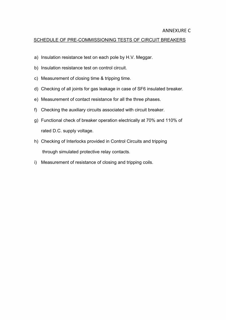
ANNEXURE C
SCHEDULE OF PRE-COMMISSIONING TESTS OF CIRCUIT BREAKERS
a) Insulation resistance test on each pole by H.V. Meggar.
b) Insulation resistance test on control circuit.
c) Measurement of closing time & tripping time.
d) Checking of all joints for gas leakage in case of SF6 insulated breaker.
e) Measurement of contact resistance for all the three phases.
f) Checking the auxiliary circuits associated with circuit breaker.
g) Functional check of breaker operation electrically at 70% and 110% of
rated D.C. supply voltage.
h) Checking of Interlocks provided in Control Circuits and tripping
through simulated protective relay contacts.
i) Measurement of resistance of closing and tripping coils.

WBPDCLEPC Bid Document
Sagardighi Thermal Power Project 1x660 MW Unit No. 5, Phase - III
Development Consultants Pvt. Ltd. Page 55 of 95 Volume : II-F/1 Section : XIII
400 KV Switchyard
ANNEXURE-BFITTINGS & ACCESSORIES
A. Circuit Breaker A.I Each Circuit Breaker shall be furnished complete with fittings and accessories as listed
below : 1. Operating mechanism complete with all accessories, fittings and double tripping coils
and closing coil, pole discrepancy feature and low pressure blocking device etc. as required.
2. Complete SF6 gas system along with valves, pressure switches, pressure gauges, SF6 gas density monitor, etc.
3. Various attachments & accessories for gas filling. 4. Two ground pads per pole suitable for termination of 75 x 10 mm GS flats. 5. Base frame and anchor bolts and nuts. 6. Set of valves, pressure gauges and pressure switches as required. 7. Auxiliary contacts and relays. 8. LOCAL/REMOTE Selector switch, TRIP/CLOSE Push Buttons. 9. Manual tripping devices with protective flap. 10. Mechanical ON-OFF indicator. 11. Operation counters. 12. Weatherproof outdoor type control cubicle and pole boxes having IPW55 enclosure. 13. Set of switch fuse units/MCCB for A.C. and D.C. supply. 14. Space heater with thermostat and ON-OFF switch. 15. Cubicle illumination lamp with ON-OFF switch. 16. 3 Pin 5A Socket with ON-OFF Switch. 17. Terminal blocks and internal wiring - lot as required. 18. Set of pre-fabricated copper pipe with fittings, clamps, and hardware for connection
between control cubicle and pole boxes as required. 19. Interconnecting wires, G.I. conduits and accessories for connection between control
cubicle and pole boxes. 20. The gas filling and internal pressure monitoring devices per pole for SF6 breakers. 21. Other standard accessories which are not specifically mentioned but supplied with
breakers of similar type and rating for efficient and trouble-free operation. 22. First filling of SF6 gas along with 15 % additional for the complete lot in non
returnable container. 23. Bimetallic terminal connectors. (Suitable for Al tube / ACSR / AAC – Horizontal /
vertical) 24. Supporting galvanized steel structure.
Page 11 of 12
ANNEXURE-B
WBPDCLEPC Bid Document
Sagardighi Thermal Power Project 1x660 MW Unit No. 5, Phase - III
Development Consultants Pvt. Ltd. Page 56 of 95 Volume : II-F/1 Section : XIII
400 KV Switchyard
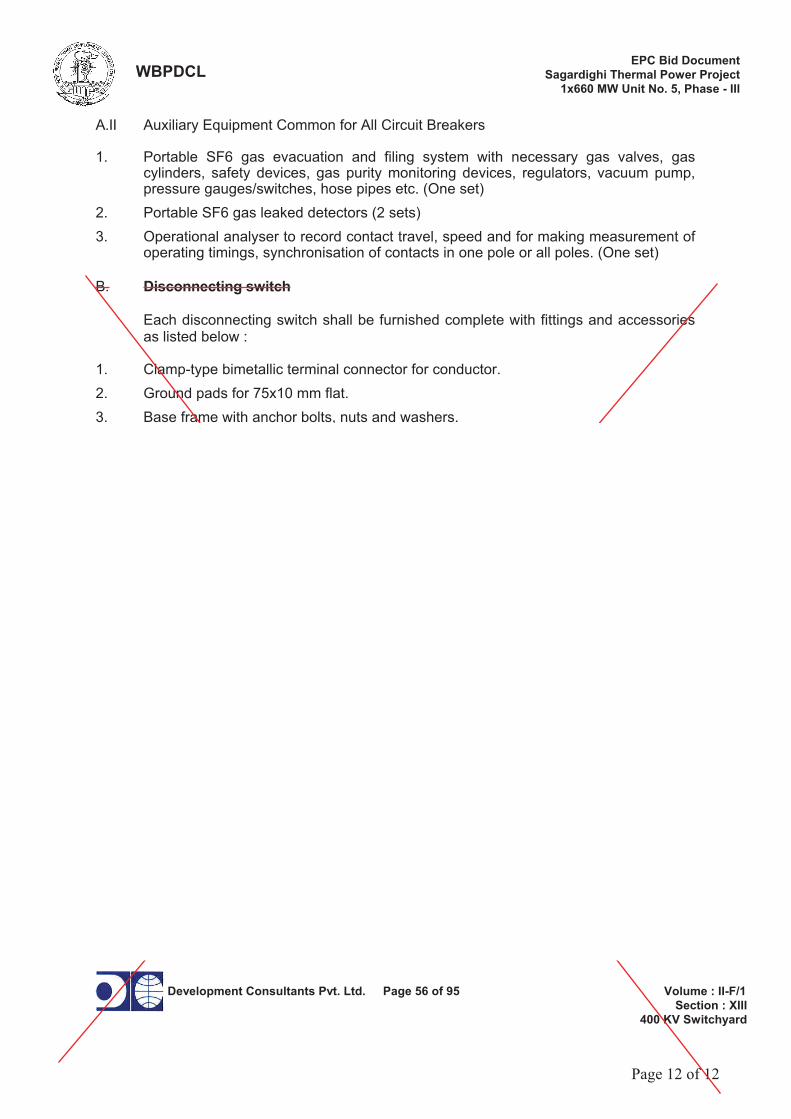
A.II Auxiliary Equipment Common for All Circuit Breakers
1. Portable SF6 gas evacuation and filing system with necessary gas valves, gas cylinders, safety devices, gas purity monitoring devices, regulators, vacuum pump, pressure gauges/switches, hose pipes etc. (One set)
2. Portable SF6 gas leaked detectors (2 sets) 3. Operational analyser to record contact travel, speed and for making measurement of
operating timings, synchronisation of contacts in one pole or all poles. (One set) B. Disconnecting switch
Each disconnecting switch shall be furnished complete with fittings and accessories as listed below :
1. Clamp-type bimetallic terminal connector for conductor. 2. Ground pads for 75x10 mm flat. 3. Base frame with anchor bolts, nuts and washers. 4. Operating mechanism with all accessories including operating rod of required length,
for disconnect switch and for earth switch 5. Starters, relays and auxiliary switches. 6. Local / Remote selector switch. 7. Open / Stop / Close push buttons. 8. Spare auxiliary switches 6 NO + 6 NC. 9. Mechanical ON-OFF indicator 10. Weather-proof mechanism box with lock and key for disconnect switch and for earth
switch, where indicated. 11. Set of fuse switches for A.C. and D.C. supply. 12. Space heater with thermostat and ON-OFF switch. 13. Internal illumination lamp with ON-OFF switch. 14. 3 pin 5A socket outlet with ON-OFF switch. 15. Terminal blocks and wiring - lot. 16. Earthing switch, if specified, complete with safety interlocks and 4 NO + 4 NC spare
auxiliary switches.
17. Flexible copper braid for grounding of operating rod. C. Current transformer
Each Current Transformer shall be furnished complete with the accessories as listed below :
1. Base frame with anchoring bolts, nuts etc. for fixing the equipment on to structure. 2. Two grounding pads with bolts and spring washers.
Page 12 of 12

The West Bengal Power Development Corporation Ltd. Bharat Heavy Electricals Ltd. 1X660 MW Thermal power extension project Unit-5 at Sagardighi- 400KV Switchyard, Doc. No. TB-SPEC-CB-445-01, Rev. No.-0, 400kV CB –
Section-3 Page 1 of 13
SECTION-3 3.0 GENERAL
This section stipulates the General Technical Requirements under the Contract and will form an integral part of the Technical Specification. The provisions under this section are intended to supplement general requirements for the materials, equipments and services covered under other respective sections and are not exclusive. However in case of conflict between the requirements specified in this section and requirements specified under other sections, the requirements specified under respective sections shall hold good.
3.1 PROJECT INFORMATION AND SYSTEM PARAMETERS
a) Customer/ Purchaser/ Owner
The West Bengal Power Development Corporation Ltd.
b) Consultant/Owner’s Engineer
Development Consultants Private Ltd. Kolkata
c) Project Title 1X660MW thermal power extension project Unit-5 at Sagardighi- 400KV Switchyard
d) Location Site is located at Manigram village of Murshidabad district in West Bengal and around 240kM from Kolkata. 13kM north of Sagardighi town by the side of the SMGR(Sagardighi Manigram –Gankar –Raghunathganj) road at a distance of 20kM from National Highway 34 . Nearest railway station is Manigram adjacent to the site on Bandel-Barhawara branch line and 6.5kM from Sagardighi railway station on Sainthia-Azimhunj line of eastern railway. Nearest Airport –Kolkata. Nearest Seaport-Kolkata/Haldia
e) Altitude 34 m above MSLf) Transport Facilities Road/Rail g) Postal Address To follow SITE CONDITIONS a) Maximum Design
ambient dry bulb temperature
50C
b) Minimum Design ambient dry bulb temperature
5C
c) Average Relative humidity ( for design)
73 %
d) Maximum relative humidity
84%
e) Pollution Severity Heavily Polluted f) Seismic zone III

The West Bengal Power Development Corporation Ltd. Bharat Heavy Electricals Ltd. 1X660 MW Thermal power extension project Unit-5 at Sagardighi- 400KV Switchyard, Doc. No. TB-SPEC-CB-445-01, Rev. No.-0, 400kV CB –
Section-3 Page 2 of 13
g) Wind velocity 47m/sec.h) Wind pressure 150kg/sq.mts i) Terrain category 2 j) Risk coefficient ( K1) 1.07k) l) Average rainfall 1389mm SYSTEM PARAMETERS
AUXILIARY POWER SUPPLY 3 phase A.C power supply
415V ±10%, 50 Hz±5%, 3-phase 4 wire,50kA, solidly earthed, combined voltage and frequency variation ±10%
1 phase A.C power supply
240V±10%, 50 Hz +3% to -5%, 1-phase AC supply
D.C. power supply 220V +10% to -15%, 2-wire , ungrounded 48V ±10%, 2 wire system positively earthed
Nominal system voltage 400 kV Highest system voltage 420 kV System voltage variation -5% to +5%Basic Impulse level( dry /wet) 1425kVp Power frequency withstand voltage dry/wet
630kVrms
Switching Impulse withstand voltage (Phase to Earth)
1050kVp
Switching Impulse withstand voltage (Phase to Phase)
1575kVp
Lightning impulse withstand voltage ( kVp between live terminals and earth.)
1425kVp
Lightning impulse withstand voltage (kVp impulse on one terminal and other terminal earthed)(across isolating distance).
1665kVp
Maximum radio interference voltage at 320kV rms phase to ground voltage
1000 micro volts for frequency between 0.5 MHZ and 2.0 MHz
Rated short time current 50 kA for 1 sec Frequency 50 Hz, +3% to -5% Creepage distance 31 mm/kV System Earthing Effectively earthed

The West Bengal Power Development Corporation Ltd. Bharat Heavy Electricals Ltd. 1X660 MW Thermal power extension project Unit-5 at Sagardighi- 400KV Switchyard, Doc. No. TB-SPEC-CB-445-01, Rev. No.-0, 400kV CB –
Section-3 Page 3 of 13
3.2 GENERAL TECHNICAL REQUIREMENT
3.2.1 TYPE TESTS
All equipment/systems to be supplied shall conform to type tests as per relevant standards and proven type. The Bidder / Contractor shall furnish the reports of all the type tests carried out in within last five years from date of LOA ( i.e. 27‐12‐2018 ) as listed in relevant clauses in respective electrical specification and relevant standards for all components / equipment / systems. These reports should be for the tests conducted on identical/similar components/equipment/systems to those offered/proposed to be supplied under this contract.
Type tests done in an independent government laboratory or in the presence of representative of State Electricity Board or other reputed public undertakings, the type test reports of the same shall be submitted for scrutiny /approval. If these are found suitable and technically acceptable, conducting of type tests shall be waived off. In case Contractor is not able to submit report of type test(s) conducted in last five years, or in case type test report(s) are not found to be meeting the specification/relevant standard requirements, then all such tests shall be conducted under this contract by the Bidder free of cost to Employer/Purchaser, and reports shall be submitted for approval. No charges shall be paid under this contract. All acceptance and routine tests as per relevant standards and specification shall be deemed to be included in the bid price. Following additional type tests are to be conducted for EHV circuit breaker:
a. Short line fault test b. Out of phase making and breaking test as per IEC. c. Rated line charging current breaking test. The breaker shall be able to interrupt the line
charging current with a test voltage of 1.4 p.u. instead of 1.2 p.u. as per IEC. d. Test to demonstrate ability to withstand 2.5 times the rated voltage across the open
circuit breaker at & below lockout pressure. e. Seismic withstand test in unpressurised condition.
3.2.2 CODES AND STANDARDS
All materials and equipment shall generally comply in all respect with the latest edition of relevant international electro-technical commission (IEC) or any other internationally accepted standard which ensure equal or better quality or relevant Indian standard(IS) mentioned against each equipment and this specification.
3.3 MATERIAL/WORKMANSHIP
3.3.1 General Requirements
Where the specification does not contain characteristics with reference to workmanship, equipment, materials and components of the covered Equipment it is understood that the same must be new, of highest grade of the best quality of their kind conforming to best engineering practice and suitable for the purpose for which they are intended.

The West Bengal Power Development Corporation Ltd. Bharat Heavy Electricals Ltd. 1X660 MW Thermal power extension project Unit-5 at Sagardighi- 400KV Switchyard, Doc. No. TB-SPEC-CB-445-01, Rev. No.-0, 400kV CB –
Section-3 Page 4 of 13
The design of the Works shall be such that installation, future expansions, replacements and general maintenance may be undertaken with a minimum of time and expenses. Each component shall be designed to be consistent with its duty and suitable factors of safety, subject to mutual agreements and shall be used throughout the design. All joints and fastenings shall be devised, constructed and documented so that the component parts shall be accurately positioned and restrained to fulfill their required function. In general screw threads shall be standard metric threads. The use of other thread forms will only be permitted when prior approval has been obtained from purchaser. Whenever possible, all similar part of the Works shall be made to gauge and shall also be made interchangeable with similar parts. All spare parts shall be interchangeable with, and shall be made of the same materials and workmanship as the corresponding parts of the Equipment supplied under the Specification. Where feasible, common component units shall be employed in different pieces of equipment in order to minimize spare parts stocking requirements. All equipment of the same type and rating shall be physically and electrically interchangeable. All materials and equipment shall be installed in strict accordance with the manufacturer's recommendation(s). Only first-class work in accordance with the best modem practices will be accepted. Installation shall be constructed as being the erection of equipment at its permanent location. This, unless otherwise specified, shall include unpacking, cleaning and lifting into position, grouting, leveling, aligning, coupling of or bolting down to previously installed equipment bases/foundations, performing the alignment check and final adjustment prior to initial operation, testing and commissioning in accordance with the manufacturer's tolerances and instructions and the Specification. All factory assembled rotating machinery shall be checked for alignment and adjustments made as necessary to re-establish the manufacture’s limits suitable guards shall be provided for the protection of personal on all exposed rotating and / or moving machine parts and shall be designed for easy installation and removal for maintenance purpose. The spare equipment(s) shall be installed at designated locations and tested for healthiness. The Contractor shall apply oil and grease of the proper specification to suit the machinery, as is necessary for the installation of the equipment. Lubricants used for installation purposes shall be drained out and the system flushed through where necessary for applying the lubricant required for operation. The Contractor shall apply all operational lubricants to the equipment installed by him. All oil, grease and other consumables used in the Works/ Equipment shall be purchased in India unless the Contractor has any special requirement for the specific application of a type of oil or grease not available in India. In such is the case he shall declare in the proposal, where such oil or grease is available. He shall help purchaser in establishing equivalent Indian make and Indian Contractor. The same shall be applicable to other consumables too.
3.3.2 Provisions For Exposure to Hot and Humid climate
Outdoor equipment supplied under the specification shall be suitable for service and storage under tropical conditions of high temperature, high humidity, heavy rainfall and environment favorable to the growth of fungi and mildew. The indoor equipments located in non-air conditioned areas shall also be of same type.

The West Bengal Power Development Corporation Ltd. Bharat Heavy Electricals Ltd. 1X660 MW Thermal power extension project Unit-5 at Sagardighi- 400KV Switchyard, Doc. No. TB-SPEC-CB-445-01, Rev. No.-0, 400kV CB –
Section-3 Page 5 of 13
3.4 PAINTING
The painting of equipment shall be as follows:
Epoxy based with suitable additives. The thickness of finish coat shall be minimum 80 microns (minimum total DFT shall be 100 microns). However in case electrostatic process of painting is offered for any electrical equipment, minimum paint thickness of 80 microns shall be acceptable for finish coat.
Painting process shall be of powder coating type. All surface shall be cleaned , phosphated and given two coats of rust –resistant primer followed by two coats of finish paints . The interior of all panels cabinets and enclosures shall be finished with gloss white enamel. Two final powder coats of synthetic enamel paint of light grey shade(631 of IS-5) shall be given to exterior surface of all the panels. Sufficient quantities of touch paint shall be furnished for application at site. All The indoor cubicles shall be of same colour scheme and for other miscellaneous items, colour scheme will be approved by the purchaser.
3.5 PROTECTION
All coated surfaces shall be protected against abrasion, impact, discoloration and any other damages. All exposed threaded portions shall be suitably protected with either a metallic or a non-metallic protecting device. All ends of all valves, piping and conduit equipment connections shall be properly sealed with suitable devices to protect them from damage.
All equipment accessories and wiring shall have fungus protection, involving special treatment of insulation and metal against fungus, insects and corrosion. The parts which are likely to get rusted, due to exposure to weather should also be properly treated and protected in a suitable manner. Screens of corrosion resistant material shall be furnished on all ventilating louvers to prevent entry of insects.
3.6 FUNGISTATIC VARNISH
Besides the space heaters, special moisture and fungus resistant varnish shall be applied on the parts, which may be subjected or predisposed to the formation of fungi due to the presence or deposit of nutrient substances. The varnish shall not be applied to any surface of part where the treatment will interface with the operation or performance of the equipment. Such surfaces or parts shall be protected against the application to the varnish.
3.7 SURFACE FINISH
All interiors and exteriors of tanks, control cubicles and other metal parts shall be throughly cleaned to remove all rust, scales, corrosion, greases or other adhering foreign matter. All steel surfaces in contact with insulating oil as far as accessible, shall be painted with not less than two coats of heat resistant, oil insoluble, insulating paints. All metal surfaces exposed to atmosphere shall be given two primer coats of zinc chromate and

The West Bengal Power Development Corporation Ltd. Bharat Heavy Electricals Ltd. 1X660 MW Thermal power extension project Unit-5 at Sagardighi- 400KV Switchyard, Doc. No. TB-SPEC-CB-445-01, Rev. No.-0, 400kV CB –
Section-3 Page 6 of 13
two coats of epoxy paint with epoxy base thinner. All metal parts not accessible for painting shall be made of corrosion resisting material. All machine finished or bright surfaces shall be coated with a suitable preventive compound and suitably wrapped or otherwise protected. All paints shall be carefully selected to withstand tropical heat and extremes of weather within the limit specified. The paint shall not scale off or wrinkle or be removed by abrasion due to normal handling. All external painting shall be as per shade no. 631 of IS:5.
3.8 GALVANIZING
All ferrous parts including all sizes of nuts, bolts, Plain and spring washers, support channels, structures, shall be hot dip galvanized conforming to latest version of IS:2629 or any other equivalent authoritative standard. However, hardware less than M12 size shall be electro-galvanized. Minimum weight of zinc coating shall be 610 gm/sq.m and minimum thickness of coating shall be 85 microns for all items thicker than 6mm. For items lower than 6 mm thickness, requirement of coating shall be as per relevant ASTM.
3.9 PACKING
The following details are to be clearly indicated in the material forwarding documents: a) Name and address of the consignee.
b) Purchase order number. c) Name of supplier/s. d) Description of equipment / material. e) Net weight. f) Gross weight. Each package shall be accompanied by a packing note (in weather proof paper). All the equipment shall be suitably protected, coated, covered or boxed and crated to prevent damage or deterioration during transit, handling and storage at Site till the time of erection. On request of the purchaser, the Contractor shall also submit packing details/associated drawing for any equipment material under his scope of supply, to facilitate the purchaser to repack any equipment/ material at a later date, in case the need arises. Any material found short inside the packing cases shall be supplied by the supplier without any extra cost. The cases containing easily damageable material shall be very carefully packed and marked with appropriate caution symbol i.e. fragile, handle with care, use no Hooks etc.
3.10 HANDLING, STORING AND INSTALLATION
Contractor may engage manufacturer's Engineers to supervise if required for unloading, transportation to site, storing, testing and commissioning of the various equipment being procured by them separately. In case of any doubt/misunderstanding as to the correct interpretation of manufacturer's drawings or instructions, necessary clarifications shall be obtained from the purchaser. Contractor shall be held responsible for any damage to the equipment consequent to not following manufacturer's drawings/instructions correctly.
Where assemblies are supplied in more than one section, contractor shall make all necessary mechanical and electrical connections between sections including the connection between buses.

The West Bengal Power Development Corporation Ltd. Bharat Heavy Electricals Ltd. 1X660 MW Thermal power extension project Unit-5 at Sagardighi- 400KV Switchyard, Doc. No. TB-SPEC-CB-445-01, Rev. No.-0, 400kV CB –
Section-3 Page 7 of 13
Contractor shall also do necessary adjustments/alignments necessary for proper operation of circuit breakers, isolators and their operating mechanisms. All components shall be protected against damage during unloading, transportation, storage, installation, testing and commissioning.
Contractor shall be responsible for examining all the shipment immediately of any damage, shortage, discrepancy etc. for the purpose of Purchaser’s information only. Any demurrage, pilferage and other such charges claimed by the transporters, railways etc. shall be to the account of the Contractor. The Contractor shall be fully responsible, for the equipment/material until the same is handed over to the purchaser in an operating condition after commissioning.
The minimum phase to earth, phase to phase and section clearance along-with other technical parameters for the various switchyard voltage levels to be maintained shall be strictly as per the approved drawings.
The design and workmanship shall be in accordance with the best engineering practices to ensure satisfactory performance throughout the service life. If at any stage during the execution of the Contract, it is observed that the erected equipment(s) do not meet the above minimum clearances, the Contractor shall immediately proceed to correct the discrepancy at his risks and costs.
3.11 DEGREE OF PROTECTION
The enclosures of the Control Cabinets, Junction boxes and Marshalling boxes panels etc to be installed shall be provided with degree of protection as detailed here under:
a) Installed out door: IP-55
b) Installed indoor in air conditioned area: IP-31
c ) Installed in covered area IP:52
d) Installed indoor-in non-air-conditioned area where possibilities of entry of water is limited:IP-41
e) For LT switchgear (AC & DC distribution Boards): IP-54
The degree of protection shall be in accordance with IS:13947, (Part-1)/IEC-947(Part-1). Type test report/or degree of protection test on each type of the box shall be submitted for approval.
3.12 RATING PLATES, NAME PLATES AND LABELS
Type or serial number together with details of the loading conditions under which the item of the substation in question has designed to operate and such diagram plates as may require by the Purchaser. The rating plate of each equipment shall be according to IEC requirements.
All such nameplate instruction plates, rating plates shall be bilingual with Hindi inscription first followed by English. Alternately two separate plates one with Hindi and other with English inscriptions may be provided. All measurements shall be in M.K.S units.

The West Bengal Power Development Corporation Ltd. Bharat Heavy Electricals Ltd. 1X660 MW Thermal power extension project Unit-5 at Sagardighi- 400KV Switchyard, Doc. No. TB-SPEC-CB-445-01, Rev. No.-0, 400kV CB –
Section-3 Page 8 of 13
3.13 EARTHING
Circuit breakers shall be provided with two grounding pads suitable for connection to galvanized steel flat. Control panels, Relay panel, outdoor marshalling boxes, Junction boxes, lighting panels and distribution board shall be provided with two grounding pads, for connection to galvanized steel flat. The two pads shall be provided, one each at the middle of the two opposite sides of the bottom frame of the equipment. Earthling of hinged door shall be done by using a separate earth wire.
3.14 TERMINAL BLOCKS AND WIRING
Control and instrument leads from the switchboards or from other equipment will be brought to terminal boxes or control cabinets in conduits. All Inter-phase and external connections to equipment or to control cubicles will be made through terminal blocks.
Terminal blocks shall be 1100 V grade box –clamp type and have continuous rating to carry the maximum expected current on the terminals. Those shall be of molded piece complete with insulated barriers stud type terminals, washers nuts and lock nuts. Screw clamp, overall insulated, insertion type, rail mounted terminals can be used in place of stud type terminals. But preferably the terminal blocks shall be non-disconnecting stud type equivalent to Elmex type CATM4, Phoenix cage clamp type of Wedge or equivalent. The Insulating material of terminal block shall be nylon 6.6 which shall be free of halogens, fluorocarbons etc.
Terminal block for current transformer and voltage transformer secondary leads shall be provided with test links and isolating facilities. The current transformer secondary leads shall also be provided with short circuiting and earthing facilities.
The terminal shall be that maximum contact area is achieved when a cable is terminated. The terminal shall have a locking characteristic to prevent cable from escaping from the terminal clamp unless it is done intentionally. The conducting part in contact with cable shall preferably be tinned or silver plated however Nickel plated copper or zinc plated steel shall also be acceptable. The terminal blocks shall be of extensible design. The terminal blocks shall have locking arrangement to prevent its escape from the mounting rails.
The terminal blocks shall be fully enclosed with removable covers of transparent, non deteriorating type plastic material. Insulating barriers shall be provided between the terminal blocks. These barriers shall not hinder the operator from carrying out the wiring without removing the barriers.
Unless otherwise specified terminal blocks shall be suitable for connecting the following conductors on each side.
All circuits except CT circuits : Minimum of 2 nos. of 2.5 sq.mm, copper flexible.
All CT circuits : Minimum of 4 nos. of 2.5 sq.mm, copper flexible..

The West Bengal Power Development Corporation Ltd. Bharat Heavy Electricals Ltd. 2X500MW Thermal power extension project Unit-3 & 4 at Sagardighi- 400KV Switchyard, Doc. No. TB-348-316-001, Rev. No.-0, 400kV CB –
Section-3 Page 9 of 13
The arrangements shall be in such a manner so that it is possible to safely connect or disconnect terminals on live circuits and replace fuse links when the cabinet is live. At least 20 % spare terminals shall be provided on each panel/cubicle/box and these spare terminals shall be uniformly distributed on all terminals rows.
There shall be a minimum clearance of 250mm between the first bottom row of terminal block and the associated cable gland plate. Also the clearance between two rows of terminal blocks shall be a minimum of 150 mm. The Supplier shall furnish all wire, conduits and terminals for the necessary inter-phase electrical connection (where applicable) as well as between phases and common terminal boxes or control cabinets.
All input and output terminals of each control cubicle shall be tested for surge withstand capability in accordance with the relevant IEC Publications, in both longitudinal and transverse modes. The supplier shall also provide all necessary filtering, surge protection, interface relays and any other measures necessary to achieve an impulse withstand level at the cable interfaces of the equipment.
3.15 CONTROL CABINETS, JUNCTION BOXES, TERMINALS BOXES AND MARSHALLING BOXES FOR OUTDOOR EQUIPMENTS
All types of boxes, cabinets etc. shall generally conform to and be tested in accordance with IS-5039, IS-8623 or IEC-439, as applicable and the clause given below.
Control cabinet, Junction boxes, Marshalling boxes & Terminal boxes shall be made of CRCA sheet steel of minimum 2 mm thickness. The thickness of door s/covers shall not be less than 1.6 mm. The box shall be properly braced to prevent wobbling. There shall be sufficient reinforcement to provide level surfaces, resistance to vibrations and rigidity during transportation and installation. Cabinet/boxes shall be free standing floor mounting type, wall mounting type or pedestal mounting type as per requirements.
Cabinet /boxes shall be provided with double hinged doors with padlocking arrangements. The distance between two hinges shall be adequate to ensure uniform sealing pressure against atmosphere. The quality of gaskets shall be such that it does not get damaged/cracked during the operation of the equipment.
All door, removable covers and plates shall be gasketed all around with suitably profiled Neoprene gaskets. The gasket shall be tested in accordance with approved quality plan. The quality of gasket shall be such that it does not get damaged /cracked during the years of the equipment or its major overhaul whichever is earlier. All gasketed surfaces shall be smooth, straight and reinforced if necessary to minimize distortion and to make a tight seal. Ventilating Louvers, if provided, shall have screen and filters. The screen shall be fine wire mesh made of brass.
All boxes/cabinets shall be designed for the entry of cables from bottom by means of weather proof and dust-proof connections. Boxes and cabinets shall be designed with generous clearances to avoid interference between the wiring entering from below and any terminal blocks

The West Bengal Power Development Corporation Ltd. Bharat Heavy Electricals Ltd. 2X500MW Thermal power extension project Unit-3 & 4 at Sagardighi- 400KV Switchyard, Doc. No. TB-348-316-001, Rev. No.-0, 400kV CB –
Section-3 Page 10 of 13
or accessories mounted within the box or cabinet. Suitable cable gland plate projecting at least 150 mm above from the base of the Marshalling Kiosk/box shall be provided for this purpose along with the proper blanking plates. Necessary number of cable glands shall be supplied and fitted on this gland. The gland shall project at least 25mm above gland plate to prevent entry of moisture in cable crutch. Gland plate shall have provision for some future glands to be provided later, if required.
3.16 SPACE HEATERS
The heater shall be suitable for continuous operation at 240 V AC supply voltage and shall be provided with on – off switch and fuse shall be provided for heater.
One or more adequately rated, thermostatically connected heaters shall be supplied to prevent condensation in any compartment. The heater shall be installed in the lower portion of the compartment and electrical connections shall be made from below the heater to minimize deterioration of supply wire insulation. The heaters shall be suitable to maintain the compartment temperature to prevent condensation.
The heaters shall be suitably designed to prevent any contact between the heater wire and air and shall consist of coiled resistance wire centered in metal sheath and completely encased in a highly compacted powder of Magnesium Oxide or other material having equal heat conduction and electrical insulation properties, or they shall consist of a resistance wire wound on a ceramic and completely covered with a ceramic material to prevent any contact between the wire and air. Alternatively, they shall consist of resistance wire mounted into a tubular ceramic body built into an envelope of stainless steel or the resistance wire is wound on a tubular ceramic body and embedded in glaze the surface temperature of the heaters shall be restricted to a value which will not shorten the life of the heater sheaths or that of insulated wire or other component in the compartments.
3.17 QUALITY
BHEL quality plan to be followed subject to TBEM / customer's approval.
3.18 DOCUMENTATION 3.18.1 LIST OF DOCUMENTS
The bidder shall submit a detailed list of drawings / documents along with the bid proposal which he intends to submit to the Employer after award of the contract.
The supplier shall necessarily submit all the drawings / documents unless any thing is waived.
All engineering data submitted by the Contractor after final process including review and approval by the Employer shall form part of the Contract Document and the entire works

The West Bengal Power Development Corporation Ltd. Bharat Heavy Electricals Ltd. 2X500MW Thermal power extension project Unit-3 & 4 at Sagardighi- 400KV Switchyard, Doc. No. TB-348-316-001, Rev. No.-0, 400kV CB –
Section-3 Page 11 of 13
performed under this specification shall be performed in strict conformity, unless otherwise expressly requested by the Employer in Writing.
3.18.2 DRAWINGS
All drawings submitted by the Contractor including those submitted at the time of bid shall be in sufficient detail to indicate the type, size, arrangement, material description, Bill of Materials, weight of each component, break-up for packing and shipment, the external connections, fixing arrangement required, the dimensions required for installation and interconnections with other equipment and materials, clearances and spaces required for installation and interconnection between various portions of equipment and any other information specifically requested in the specifications.
Each drawing submitted by the Contractor shall be clearly marked with the name of the Employer, name of consultant, the unit designation, contract no., and the name of the Project. If standard catalogue pages are submitted, the applicable items shall be indicated therein. All titles, noting, markings and writings on the drawing shall be in English. All the dimensions should be in metric units.
Further work by the Contractor shall be in strict accordance with these drawings and no deviation shall be permitted without the written approval of the Employer if so required.
All manufacturing and fabrication work in connection with the equipment prior to the approval of the drawing shall be at the Contractor’s risk. The Contractor may make any changes in the design which are necessary to make the equipment conform to the provisions and intent of the Contract and such changes will again be subject to approval by the Employer. Approval of Contractor’s drawing or work by the Employer shall not relieve the contractor of any of his responsibilities and liabilities under the Contract.
3.18.3 APPROVAL PROCEDURE
The scheduled dates for the submission of these as well as for, any data/information to be furnished by the Employer would be discussed and finalized at the time of award. The supplier shall also submit required no. of copies as mentioned in this specification of all drawings/design documents/test reports for approval by the Employer. The following schedule shall be followed generally for approval.
i. Initial submission of drawings and data sheet
Within 2 (two) weeks from PO date.
ii. Approval/comments/by employer on Initial submission
Within 2 (two) weeks of receipt
iii. Resubmission Within 1 (one) weeks (whenever from date of comments required) Including both ways postal time.
iv. Approval or comments Within 1 week of receipt of resubmission
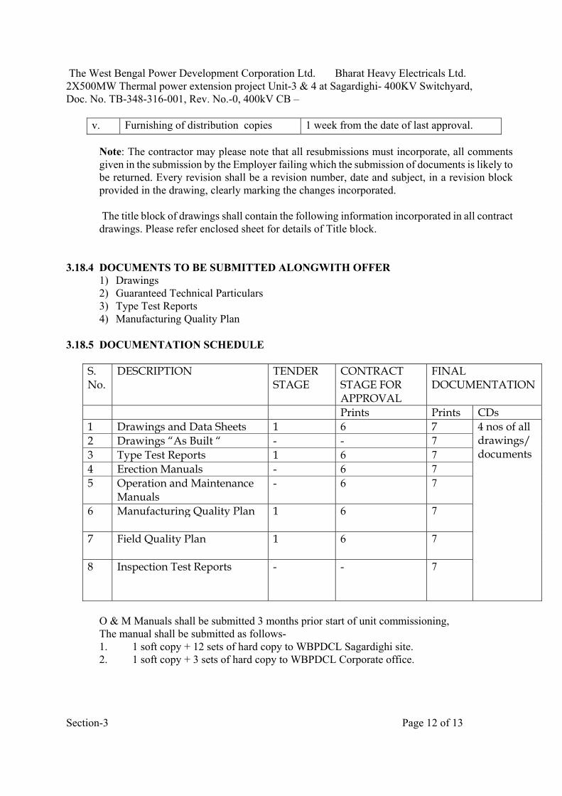
The West Bengal Power Development Corporation Ltd. Bharat Heavy Electricals Ltd. 2X500MW Thermal power extension project Unit-3 & 4 at Sagardighi- 400KV Switchyard, Doc. No. TB-348-316-001, Rev. No.-0, 400kV CB –
Section-3 Page 12 of 13
v. Furnishing of distribution copies 1 week from the date of last approval.
Note: The contractor may please note that all resubmissions must incorporate, all comments given in the submission by the Employer failing which the submission of documents is likely to be returned. Every revision shall be a revision number, date and subject, in a revision block provided in the drawing, clearly marking the changes incorporated.
The title block of drawings shall contain the following information incorporated in all contract drawings. Please refer enclosed sheet for details of Title block.
3.18.4 DOCUMENTS TO BE SUBMITTED ALONGWITH OFFER 1) Drawings 2) Guaranteed Technical Particulars 3) Type Test Reports 4) Manufacturing Quality Plan
3.18.5 DOCUMENTATION SCHEDULE
S. No.
DESCRIPTION TENDER STAGE
CONTRACT STAGE FOR APPROVAL
FINAL DOCUMENTATION
Prints Prints CDs 1 Drawings and Data Sheets 1 6 7 4 nos of all
drawings/documents
2 Drawings “As Built “ - - 7 3 Type Test Reports 1 6 7 4 Erection Manuals - 6 7 5 Operation and Maintenance
Manuals - 6 7
6 Manufacturing Quality Plan 1 6 7
7 Field Quality Plan 1 6 7
8 Inspection Test Reports - - 7
O & M Manuals shall be submitted 3 months prior start of unit commissioning, The manual shall be submitted as follows- 1. 1 soft copy + 12 sets of hard copy to WBPDCL Sagardighi site. 2. 1 soft copy + 3 sets of hard copy to WBPDCL Corporate office.

The West Bengal Power Development Corporation Ltd. Bharat Heavy Electricals Ltd. 2X500MW Thermal power extension project Unit-3 & 4 at Sagardighi- 400KV Switchyard, Doc. No. TB-348-316-001, Rev. No.-0, 400kV CB –
Section-3 Page 13 of 13
Soft copies of drawings at contract stage shall also be submitted in PDF format.
Drawings will also be submitted in mini cartridges in AUTOCAD Release -14 package or any other CAD package along with conversion files for all major items.
Final Documentation shall be submitted in bound volumes with Customer & Project etc. written on top.


WBPDCL EPC Bid Document
Sagardighi Thermal Power Project1x660 MW Unit No. 5, Phase – III
Doc No: TB-SPEC-CB-445-01
Development Consultants Pvt. Ltd. Page 1 of 10 Volume : IIID
Sch-IIID/9400 KV Switchyard equipment
SCHEDULE-IIID/9
GUARANTEED TECHNICAL PARTICULAR
400KV SWITCHYARD EQUIPMENT AND ACCESSORIES
CIRCUIT BREAKER 420 KV 1.0 Name of Manufacturer : 2.0 Reference standard : 3.0 Type : 4.0 Service : 5.0 Pole Nos. : 6.0 Rated Voltage KV rms : 7.0 Rated Frequency Hz : 8.0 Mechanical Endurance Class : 9.0 Electrical Endurance Class : 10.0 Restrike Probability Class : 11.0 Electromagnetic Compatibility
(EMC) :
12.0 Rated Insulation Level : 13.1 Rated Lightning Impulse withstand
voltage KVpeak
a) Between phase to earth : b) Between phases and CB open : c) Across isolating distance
:
13.2 Rated Switching Withstand Voltage KV peak
a) Between phase to earth : b) Between phases :

WBPDCL EPC Bid Document
Sagardighi Thermal Power Project1x660 MW Unit No. 5, Phase – III
Doc No: TB-SPEC-CB-445-01
Development Consultants Pvt. Ltd. Page 2 of 10 Volume : IIID
Sch-IIID/9400 KV Switchyard equipment
c) Across isolating distance : 13.3 Rated one minute power frequency
withstand voltage KV rms
a) Between phase to earth : b) Between phases : c) Across isolating distance : 14.0 Corona extinction voltage with CB
open or close in normal atmospheric conditions KV rms(min)
:
15.0 Max. radio interference voltage at
1.1 Urated /√3 Micro-Volts :
16.0 Rated normal Current at site
condition Amps :
17.0 Limit of temperature rise : 18.0 Rated Making & Breaking Capacity 18.1 Rated Short-circuit breaking
current (Symmetrical) KA rms :
18.2 Percentage D.C. component : 18.3 Rated short-circuit making current
KA peak :
18.4 Rated peak withstand current KA
peak :
18.5 Rated short time withstand current
for rated duration of 1 sec. KA rms :
18.6 Rated line charging breaking
current Amps rms :
18.7 Rated Out of phase breaking
current In % of rated Short Ckt. Breaking current
:
18.8 Rated Out of phase making current
In % of rated out of phase Breaking current
:
18.9 Characteristic for short-line fault :

WBPDCL EPC Bid Document
Sagardighi Thermal Power Project1x660 MW Unit No. 5, Phase – III
Doc No: TB-SPEC-CB-445-01
Development Consultants Pvt. Ltd. Page 3 of 10 Volume : IIID
Sch-IIID/9400 KV Switchyard equipment
related to rated short-circuit breaking current
18.10 Rated capacitive switching
breaking (Ams)/ in rush making current (KA peak)
:
18.11 TRV Characteristics : 19.0 Inductive current breaking
capability without exceeding over voltage by 2.0 pu.
:
20.0 First pole to clear factor : 21.0 Operating mechanism 21.1 Type with functional description
write-up :
21.2 Whether trip free operation with anti
pumping arrangement provided :
21.3 Spring charged mechanism a) Rated Power KW : b) Rated supply voltage, phase &
frequency and operating range V & Hz
:
c) Spring Charging time : d) Safety interlock provided : 21.4 Electro hydraulic operated
mechanism
a) Rated Power KW : b) Rated Supply Voltage, Phase
and frequency :
c) Operating Pressure and range
Kg/m2 :
d) Safety interlock provided : e) Operating Pressure of
Nitrogen Kg/m2 :
21.5 Pneumatic Operated Mechanism

WBPDCL EPC Bid Document
Sagardighi Thermal Power Project1x660 MW Unit No. 5, Phase – III
Doc No: TB-SPEC-CB-445-01
Development Consultants Pvt. Ltd. Page 4 of 10 Volume : IIID
Sch-IIID/9400 KV Switchyard equipment
a) Rated Power KW : b) Rated Supply Voltage, Phase
and frequency :
c) Operating Pressure and range
Kg/m2 :
d) Safety interlock provided : e) Air consumption like : 22.0 Opening time ms : 23.0 Closing time ms : 24.0 Rated Operating Sequence For Auto Reclosing breakers : For Non Auto Reclosing breakers : 25.0 Rated Supply Voltage and
frequency for
25.1 Closing : 25.2 Tripping : 25.3 Spring Charge Motor : 25.4 Compressor / Pump Motor : 25.5 Heater/Lamp/Socket : 26.0 Minimum Creepage distance mm : 27.0 Phase to phase spacing of terminal
conductor mm :
28.0 Elevation of lower most terminal
Conductor above Plinth level mm :
29.0 Rated Terminal Load Kgf : 30.0 Noise level (db) at the base of CB : 31.0 Mounting structure : 32.0 Seismic Acceleration : 33.0 SF6 Gas :

WBPDCL EPC Bid Document
Sagardighi Thermal Power Project1x660 MW Unit No. 5, Phase – III
Doc No: TB-SPEC-CB-445-01
Development Consultants Pvt. Ltd. Page 5 of 10 Volume : IIID
Sch-IIID/9400 KV Switchyard equipment
34.0 Total break time measured from the instant of trip circuit energization
:
34.1 At 10% breaking capacity mS : 34.2 At 100% breaking capacity mS : 35.0 Arcing time 35.1 At 10% breaking capacity mS : 35.2 At 100% breaking capacity mS : 36.0 Total length of arc. mm : 37.0 Breaks per pole No. : 38.0 Length of break per pole mm : 39.0 Contact Travel 39.1 Length of travel mm : 39.2 Rate of travel M/S : 40.0 Make time mS : 41.0 Spring charging time Sec : 42.0 Reclosing time with rated control
voltage applied and measured from the instant of trip coil energization.
42.1 Minimum dead time for first auto
reclose mS :
42.2 Range of adjustment for single
auto reclose mS :
43.0 Recovery voltage distribution
between breaks in % of single line to earth fault %
:
44.0. Type of devices, if any, to limit the
rate of restriking voltage :
45.0 Short circuit type test certificate
furnished? Yes/No
45.1 Certificate/Report No. :

WBPDCL EPC Bid Document
Sagardighi Thermal Power Project1x660 MW Unit No. 5, Phase – III
Doc No: TB-SPEC-CB-445-01
Development Consultants Pvt. Ltd. Page 6 of 10 Volume : IIID
Sch-IIID/9400 KV Switchyard equipment
45.2 Oscillogram No. : 46.0 Contacts 46.1 Type : a) Main : b) Arcing : 46.2 Material a) Main : b) Arcing : 46.3 Whether the contacts are silver
plated Yes/No :
46.4 Thickness of silver coating mm :
46.5 Contact pressure Kg/Cm2 :
47.0. Type of Arc control device : 48.0 Whether main air column and
interrupters are pressurised ? :
49.0 Maximum pressure developed in
the arcing chamber at rated breaking capacity Kg/Cm2
:
50.0 Time limit for which the breaker can
be kept open, if any :
51.0 Auxiliary Contacts 51.1 Total nos. of contacts furnished a) Normally open Nos : b) Normally closed Nos : 51.2 Spare contacts available for
interlocks in addition to those required for breaker's own operation and indication
:
a) Normally open Nos : b) Normally closed Nos :

WBPDCL EPC Bid Document
Sagardighi Thermal Power Project1x660 MW Unit No. 5, Phase – III
Doc No: TB-SPEC-CB-445-01
Development Consultants Pvt. Ltd. Page 7 of 10 Volume : IIID
Sch-IIID/9400 KV Switchyard equipment
51.3 Contact type convertible or fixed? : 51.4 Contact Rating at 220VDC 240AC a) Make and Continuous Amps : b) Break (Inductive) Amps : 52.0 Permissible variation of 220V D.C. 52.1 Closing : 52.2 Tripping : 53.0 Permissible variation of working
pressure of Breaker :
53.1 Closing : 53.2 Tripping : 54.0 Air Consumption in liters (At NTP) 54.1 Duty cycle (0-3 ' CO-3 ' CO) : 54.2 Closing : 54.3 Opening : 54.4 Total scavenging & leakage : 55.0 Volume of air receiver per pole : 56.0 Minimum blocking air pressure 56.1 Closing Ata : 56.2 Tripping : 57.0 Minimum clearance 57.1 Phase to ground mm : 57.2 Phase to phase mm : 58.0 Arrangement provided for 58.1 Pole discrepancy : 58.2 Trip free/Fixed trip : 58.3 Anti pumping :

WBPDCL EPC Bid Document
Sagardighi Thermal Power Project1x660 MW Unit No. 5, Phase – III
Doc No: TB-SPEC-CB-445-01
Development Consultants Pvt. Ltd. Page 8 of 10 Volume : IIID
Sch-IIID/9400 KV Switchyard equipment
59.0 Operating mechanism : 60.0 Power requirement at 220V D.C. 60.1 Closing coil Watt : 60.2 Tripping coil Watt :
60.3 Spring charging motor Watt : 61.0 Type of interlocks furnished 61.1 : 61.2 : 61.3 : 61.4 : 62.0 Accessories 62.1 Furnished as per Annexure?
Yes/No :
62.2 If not, Deviation sheet duly filled
up? Yes/No :
63.0 Bushings 63.1 Make : 63.2 Type : 63.3 Reference standard : 63.4 Voltage class KV : 63.5 Momentary dry withstand voltage
KV :
63.6 Visible discharge voltage KV : 63.7 One minute dry withstand voltage
KV :
63.8 One minute wet withstand voltage
KV :
63.9 Impulse withstand voltage KV peak :

WBPDCL EPC Bid Document
Sagardighi Thermal Power Project1x660 MW Unit No. 5, Phase – III
Doc No: TB-SPEC-CB-445-01
Development Consultants Pvt. Ltd. Page 9 of 10 Volume : IIID
Sch-IIID/9400 KV Switchyard equipment
63.10 Under oil puncture voltage KV : 63.11 Creepage distance, total/ Protected
mm :
63.12 Height required to remove the
bushing mm :
63.13 Permissible safe cantilever loading
on bushing :
64.0 Nature of insulating medium of
bushing :
65.0 Volume of insulating medium of bushing
:
66.0 Overall dimensions of the circuit
breaker complete with bushing, mechanism box etc. mm
:
67.0 Circuit Breaker Weight 67.1 Total Weight Kg :
67.2 Impact for foundation design to include dead load plus impact value on opening at max. interrupting rating in dead load Kg
:
68.0 Shipping dimension of the largest
package (L x B x H). mm :
69.0 Shipping weight of the heaviest
package Kg :
70.0 Spare quantity of SF6 gas
furnished? If so, indicate the total quantity
:
71.0 Number of openings, the Circuit
Breaker is capable of performing without inspection, replacement of contacts or other main parts.
71.1 At 50% rated current : 71.2 At 100% rated current : 71.3 At 50% rated breaking capacity :

WBPDCL EPC Bid Document
Sagardighi Thermal Power Project1x660 MW Unit No. 5, Phase – III
Doc No: TB-SPEC-CB-445-01
Development Consultants Pvt. Ltd. Page 10 of 10 Volume : IIID
Sch-IIID/9400 KV Switchyard equipment
71.4 At 100% rated breaking capacity :

Bharat Heavy Electricals Limited Doc No. TB-SPEC-CB-445-01 Technical Specification for CIRCUIT BREAKER
________________________________________________________________________________________ Page 1 of 4
SECTION - 5 Put a tick mark (√) on ‘YES’ if the specified requirement is met, or put a tick mark on ‘NO’, if the specified requirement is not met and give comments in the “Remarks” column.
CHECK LIST FOR 420 KV CIRCUIT BREAKERS
S. No.
PARTICULARS 420 kV Remarks
1 Rated voltage (KV rms) 420 KV YES/NO 2 Frequency (Hz). 50 YES/NO 3 Number of Poles 3 YES/NO 4 Neutral grounding Solidly earthed YES/NO 5 Rated continuous current (A) at design
Ambient temperature 3150
YES/NO
6 Type Outdoor SF6 YES/NO 7 Type of operation
Individually Operated single Poles
YES/NO
8 Rated Short circuit current breaking Capacity at rated voltage
50 KA with percentage DC Component as per IEC -62271-100 corresponding to minimum Opening time under operating Conditions specified
YES/NO
9 Symmetrical interrupting capability (kA rms)
50
YES/NO
10 Rated short circuit making current (kA peak)
125
YES/NO
11 i) Short time current carrying capability for three sec. (kA rms) ii) Out of phase breaking current capacity (kA rms)
50 12.5
YES/NO YES/NO
12 Rated operating duty
0-0.3 sec CO -3 min-CO Cycle
YES/NO
13 Reclosing
Single Phase & three phase auto closing
YES/NO
14 First pole to clear factor 1.3 YES/NO 15 Rated line charging interrupting current
at 90 deg. Leading power factor angle A (rms)
400
YES/NO
(The breaker shall be able to interrupt the rated line charging current with test voltage Immediately before opening equal to the product of U/√3 & 1.4 as per IEC: 62271-100
YES/NO
16 Temperature rise over the design ambient temperature
As per IEC: 62271 -100
YES/NO
17 Total opening time as per IEC (ms) 40 YES/NO 18 Rated opening time as per IEC (ms) 40 YES/NO

Bharat Heavy Electricals Limited Doc No. TB-SPEC-CB-445-01 Technical Specification for CIRCUIT BREAKER
________________________________________________________________________________________ Page 2 of 4
19 Total closing time (ms) Not more than 100 ms YES/NO 20 Operating mechanism spring - spring YES/NO 21 Max. difference in the instants of
Closing/opening of contacts i) Within a pole ii) Between poles (opening) iii) Between poles (closing)
As per section -1 of Technical specification
YES/NO
22 The above voltage shall be at rated control voltage and rated operating and quenching Media pressures
YES/NO
23 Trip coil closing coil voltage 220 V DC with variation as specified
YES/NO
24 Noise level at base of CB
140 dB (max.)
YES/NO
25 Rated terminal load As per IEC YES/NO 26 Auxiliary contacts
Besides requirement of Specification, The bidder shall wire up 10NO +10 NC Contacts for future use of purchaser per phase
YES/NO
27 No of terminals in common control cabinet
All contacts & control circuits to be Wired out up to common control Cabinet plus 24 terminals exclusively for Purchaser’s use.
YES/NO
28 Maximum allowable switching overvoltage Under any switching condition
2.3 p.u
YES/NO
29 Full wave impulse withstand voltage (1.2/50 microsec.) - between line terminals and ground - between terminals with circuit breaker open -across isolating distance(impulse on one terminal and other terminal earthed)
±1425 kV peak ±1425 kV peak ± 1425 kVp impulse on one terminal and 240 kVp power frequency voltage of opposite polarity on other terminal
YES/NO YES/NO
YES/NO
30 Switching impulse withstand voltage (250/2500 micro-second) dry and wet - between line terminals and ground - between phases - between terminals with circuit breaker open
± 1050 kV peak ± 1575 kV peak 900 kVp impulse on one terminal and 345 kVp power frequency voltage of opposite polarity on other terminal
YES/NO YES/NO YES/NO
31 One minute power frequency dry withstand voltage - between line terminals and ground
520 kV rms
YES/NO

Bharat Heavy Electricals Limited Doc No. TB-SPEC-CB-445-01 Technical Specification for CIRCUIT BREAKER
________________________________________________________________________________________ Page 3 of 4
- between terminals with circuit breaker open
610 kV rms YES/NO
32 Corona extinction voltage (kV rms) with Circuit Breaker in all positions
320 (min) YES/NO
33 Maximum radio interference voltage (micro volts) at 1.1 Urated/sq.rt.3 for frequency between 0.5 MHz and 2 MHz at 266 kV rms. in all positions
1000 YES/NO
34 Minimum Creepage distance:- i) Phase to ground (mm) ii) Between CB Terminals (mm)
13020 13020
YES/NO YES/NO
35 Phase to phase spacing 7000 mm YES/NO 36 Seismic acceleration 0.3g horizontal YES/NO 37 Rated Terminal Load As per IEC YES/NO 38 Thermal Rating of Auxiliary Contacts 10 A at 240 V AC YES/NO 39 Breaking Capacity of auxiliary contacts
5 A at 220V DC with circuit time constant not less than 20 ms.
YES/NO
40 Pre-insertion resistor requirement Rating (ohms) 400
NA
Minimum Electrical pre-insertion time (ms)
8
opening of PIR contacts As per Spec 41 General a) Whether OGA drawing enclosed YES/NO b) Filled in GTP furnished YES/NO c) Special cable for CSD (Interpole +
CSD to Relay Panels) included in scope YES/NO
d) Interpole cabling included in scope alongwith required Glands, Lugs etc. Termination chart shall be submitted alongwith the drawings.
YES/NO
e) All Type Test Reports as per IEC 62271 - 100, not older than 5 years prior to the date of technical bid opening, are available with bidder
YES/NO
f) Whether GI support structure included in Supply
YES/NO
g) Whether foundation bolts for breakers and cabinets included in scope of supply
YES/NO
h) Whether documentation schedule as per specification agreed by bidder.
YES/NO
i) No. of Aux. contacts per pole for purchaser’s usage
10 NO + 10 NC YES/NO
j) Min clearance in Air (mm) (i) Between Live Parts (ii) Live Part to Earth (iii) Live Part to ground with Support Structure / Stool
7000

Bharat Heavy Electricals Limited Doc No. TB-SPEC-CB-445-01 Technical Specification for CIRCUIT BREAKER
________________________________________________________________________________________ Page 4 of 4
k) Control Cabinet - Degree of Protection Type Tested for IP 55 within last 5 years
IP 55 (Min.)
YES/NO
42 Mandatory spares included in scope of supply as per section- 1
YES/NO
43 Supervision of Erection, testing and commissioning included in scope
YES/NO
44 Bidder to comply customer requirements as per Technical Specification
YES/NO

The West Bengal Power Development Corporation Ltd. Bharat Heavy Electricals Ltd. 1x660 MW Thermal power extension project Unit-5 at Sagardighi- 400KV Switchyard, Doc. No. TB-SPEC-CB-445-01, Rev. No.-0, 400kV CB – DEVIATION SCHEDULE
SECTION-5 Page 1 of 1
SCHEDULE OF TECHNICAL DEVIATIONS
Bidder shall list below all technical deviation clause wise w.r.t. tender specifications: S.No. Page No. Clause No. Deviation Reason / Justification Any deviation not specifically brought out in this section shall not be admissible for any commercial implication at later stage. Except to the technical deviations listed in this schedule, bidder’s offer shall be considered in full compliance to the tender specifications irrespective of any such deviation indicated / taken elsewhere in the submitted offer.
Date: Tenderer’s Stamp & Signature