the zackman framework - wordpress.com · zachman framework row 1 ... describes the entities...
TRANSCRIPT
The Zackman Framework
Background
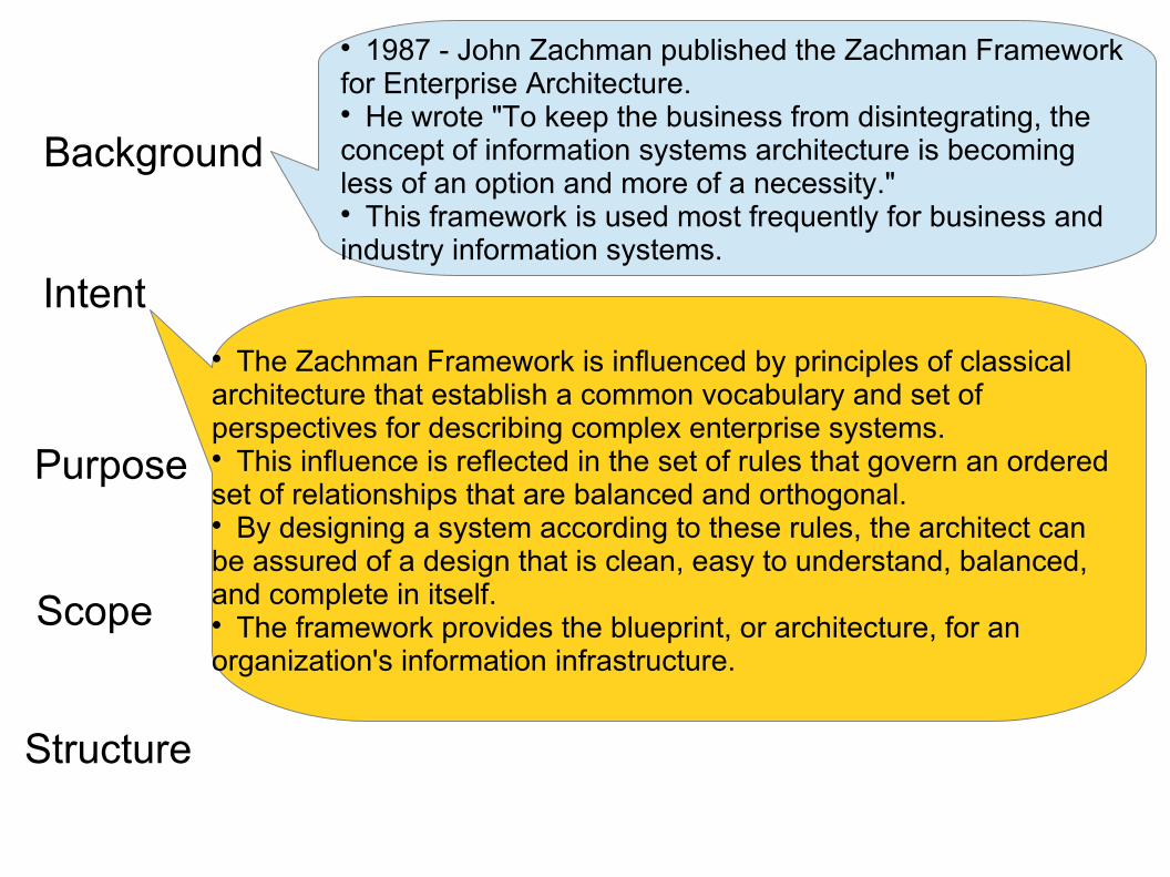
1987 - John Zachman published the Zachman Framework for Enterprise Architecture. He wrote "To keep the business from disintegrating, the concept of information systems architecture is becoming less of an option and more of a necessity." This framework is used most frequently for business and industry information systems.
The Zachman Framework is influenced by principles of classical architecture that establish a common vocabulary and set of perspectives for describing complex enterprise systems. This influence is reflected in the set of rules that govern an ordered set of relationships that are balanced and orthogonal. By designing a system according to these rules, the architect can be assured of a design that is clean, easy to understand, balanced, and complete in itself. The framework provides the blueprint, or architecture, for an organization's information infrastructure.
Intent
Purpose
Scope
Structure
Background
Intent
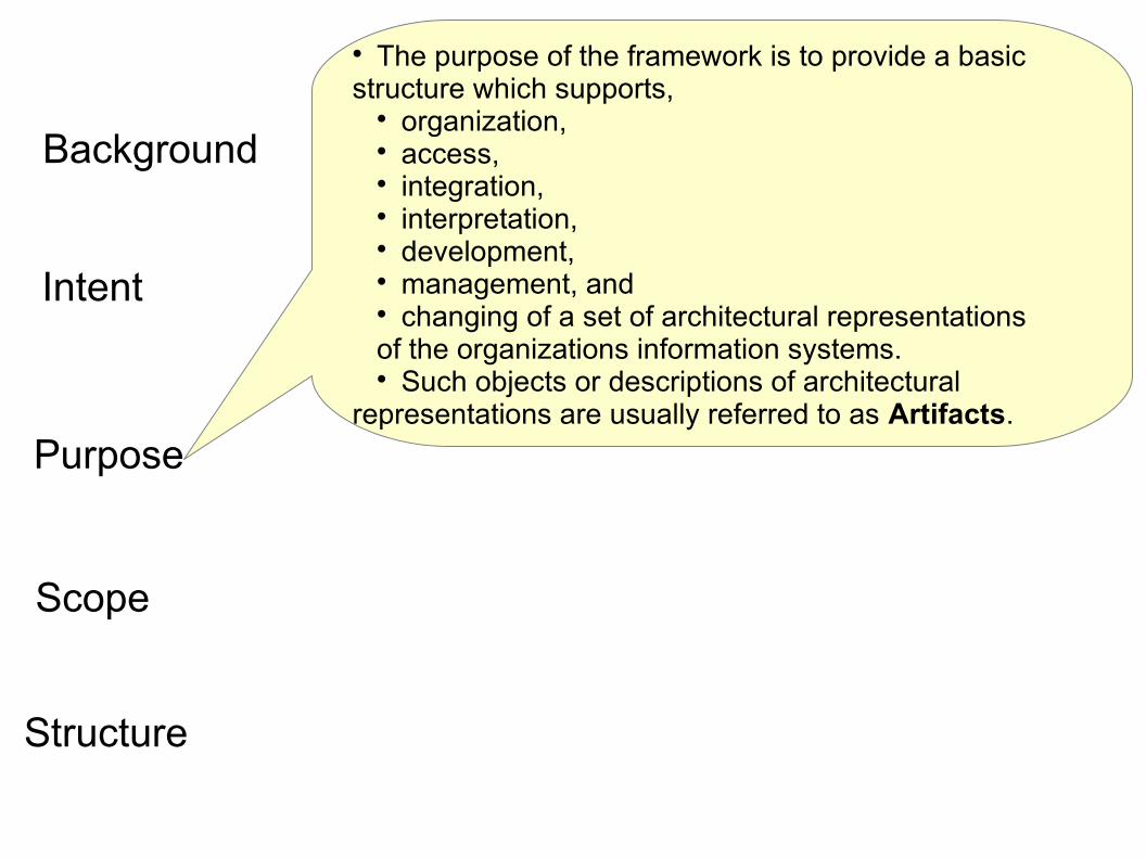
The purpose of the framework is to provide a basic structure which supports,
organization, access, integration, interpretation, development, management, and changing of a set of architectural representations of the organizations information systems. Such objects or descriptions of architectural
representations are usually referred to as Artifacts.
Purpose
Scope
Structure

Background
1987 - John Zachman published the Zachman Framework for Enterprise Architecture. He wrote "To keep the business from disintegrating, the concept of information systems architecture is becoming less of an option and more of a necessity." This framework is used most frequently for business and industry information systems.
Intent
Purpose
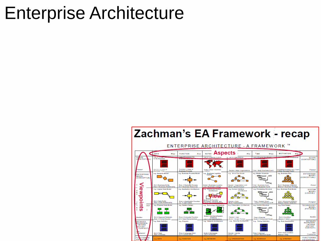
The Zachman Framework describes a holistic model of an enterprise's information infrastructure from six perspectives:
planner, owner, designer, builder, subcontractor, and the working system. There is no guidance on sequence, process, or implementation of the framework. The focus is on ensuring that all aspects of an enterprise are well-organized and exhibit clear relationships that will ensure a complete systemregardless of the order in which they are established.
Scope
Structure
Background
Intent
Purpose
Scope
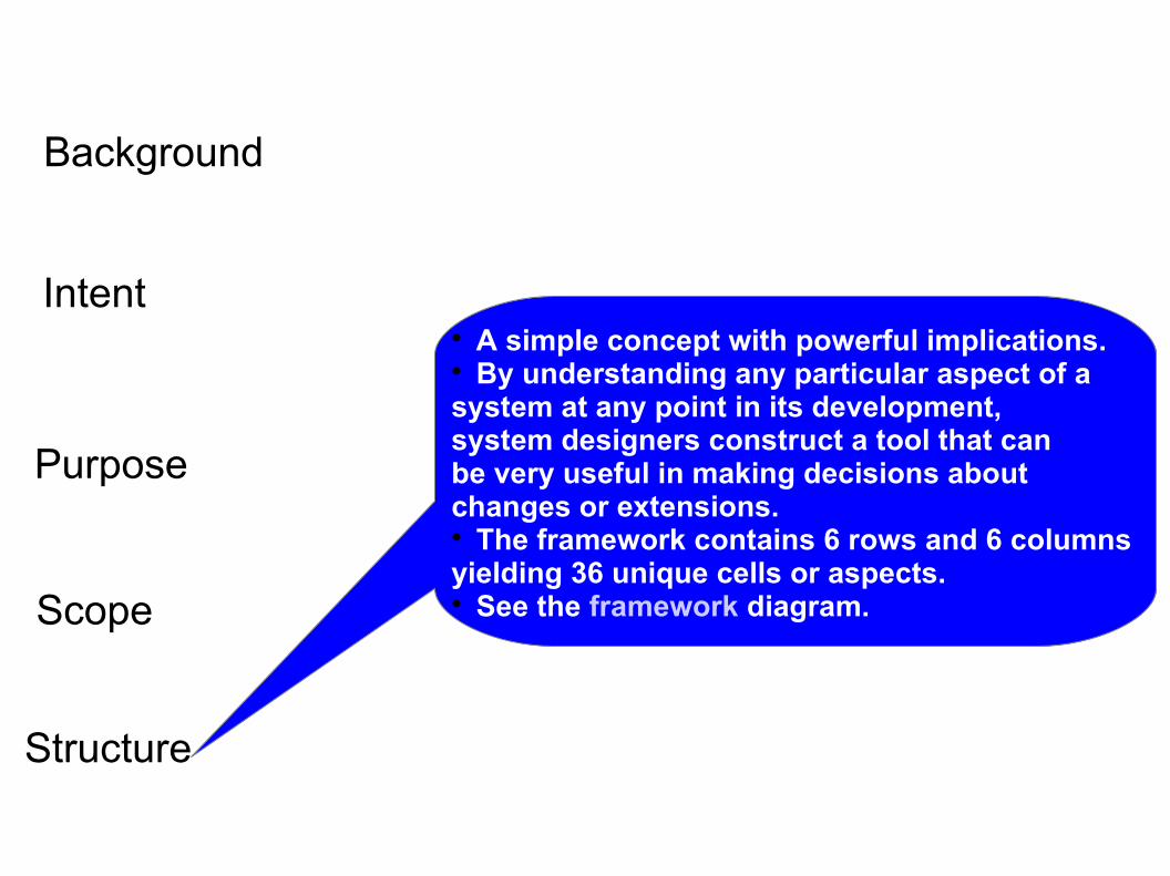
A simple concept with powerful implications. By understanding any particular aspect of a system at any point in its development, system designers construct a tool that can be very useful in making decisions about changes or extensions. The framework contains 6 rows and 6 columns yielding 36 unique cells or aspects. See the framework diagram.
Structure
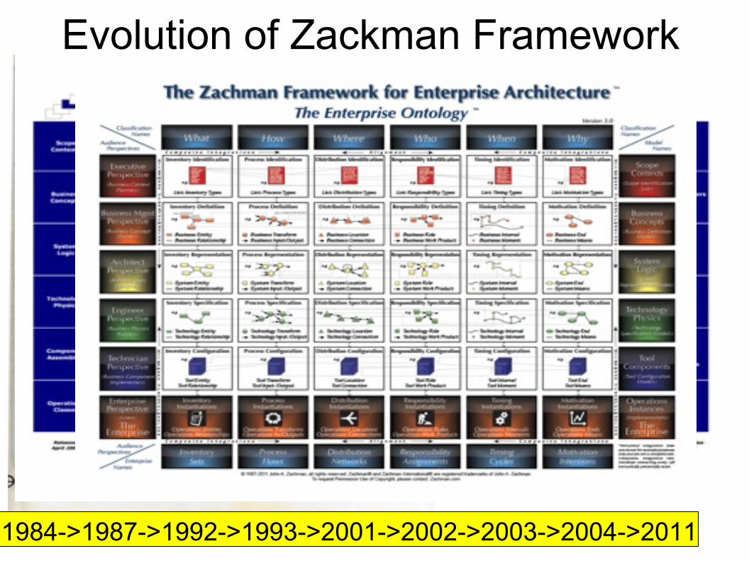
Evolution of Zackman Framework
1984->1987->1992->1993->2001->2002->2003->2004->2011
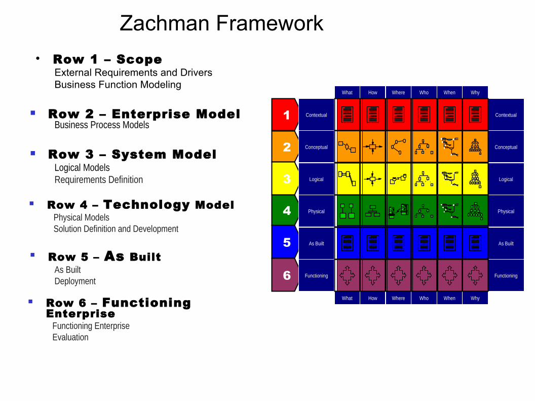
Zachman Framework Row 1 – Scope
External Requirements and DriversBusiness Function Modeling
Row 2 – Enterprise ModelBusiness Process Models
Row 3 – System ModelLogical ModelsRequirements Definition
Row 4 – Technology ModelPhysical ModelsSolution Definition and Development
Row 5 – As BuiltAs BuiltDeployment
Row 6 – Functioning Enterprise
Functioning EnterpriseEvaluation
1
2
3
4
5
6
Contextual
Conceptual
Logical
Physical
As Built
Functioning
Contextual
Conceptual
Logical
Physical
As Built
Functioning
Why
Why
Who
Who
When
When
Where
Where
What
What
How
How
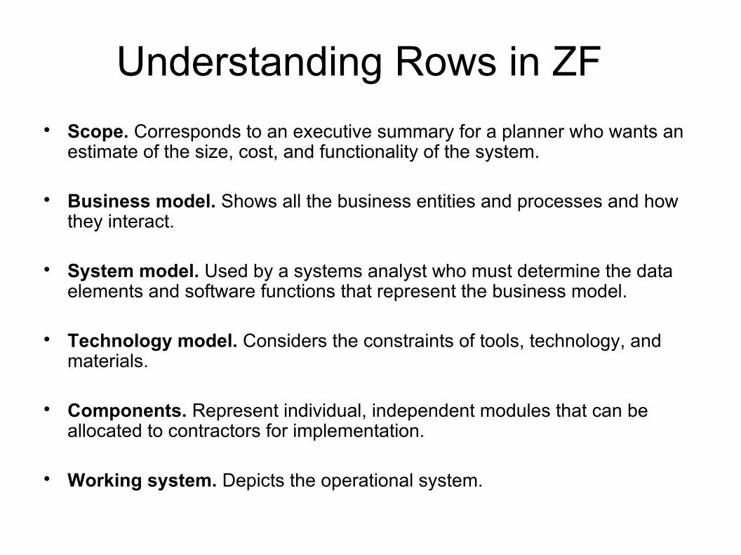
Understanding Rows in ZF Scope. Corresponds to an executive summary for a planner who wants an
estimate of the size, cost, and functionality of the system.
Business model. Shows all the business entities and processes and how they interact.
System model. Used by a systems analyst who must determine the data elements and software functions that represent the business model.
Technology model. Considers the constraints of tools, technology, and materials.
Components. Represent individual, independent modules that can be allocated to contractors for implementation.
Working system. Depicts the operational system.

Understanding Columns in ZFWHO
Represents the people relationships within the enterprise. The design of the enterprise organization has to do with the allocation of work and the structure of authority and responsibility. The vertical dimension represents delegation of authority, and the horizontal represents the assignment of responsibility.
WHEN Represents time, or the event relationships that establish performance criteria and quantitative levels for enterprise resources. This is useful for designing the master schedule, the processing architecture, control architecture, and timing devices.
WHY Describes the motivations of the enterprise. This reveals the enterprise goals and objectives, business plan, knowledge architecture, and knowledge design.
WHAT Describes the entities involved in each perspective of the enterprise. Examples include business objects, system data, relational tables, or field definitions.
HOW Shows the functions within each perspective. Examples include business processes, software application function, computer hardware function, and language control loop.
WHERE Shows locations and interconnections within the enterprise. This includes major business geographical locations, separate sections within a logistics network, allocation of system nodes, or even memory addresses within the system.
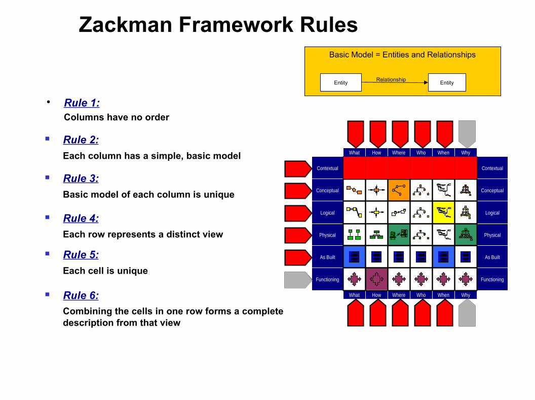
Zackman Framework Rules
Rule 1: Columns have no order
Contextual
Conceptual
Logical
Physical
As Built
Functioning
Contextual
Conceptual
Logical
Physical
As Built
Functioning
Why
Why
Who
Who
When
When
Where
Where
What
What
How
How
Rule 2:
Each column has a simple, basic model
Rule 3:
Basic model of each column is unique
Rule 4:
Each row represents a distinct view
Rule 5:
Each cell is unique
Rule 6:
Combining the cells in one row forms a complete description from that view
Basic Model = Entities and Relationships
EntityRelationship
Entity
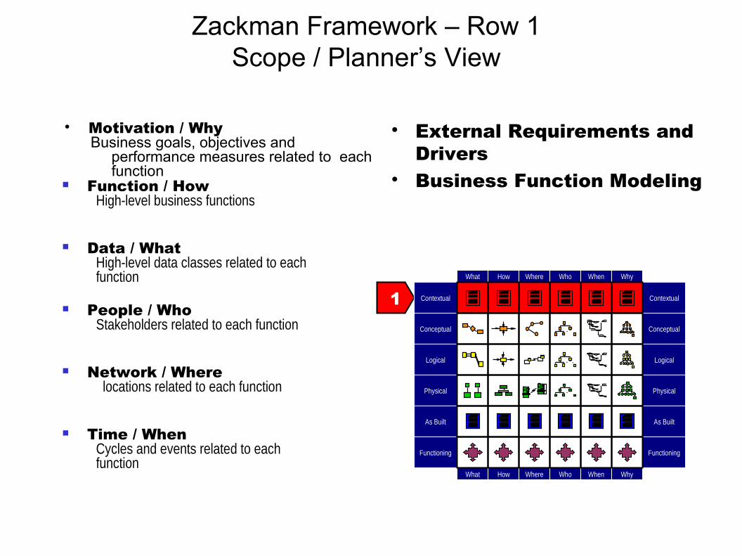
Zackman Framework – Row 1Scope / Planner’s View
External Requirements and Drivers
Business Function Modeling
Motivation / WhyBusiness goals, objectives and
performance measures related to each function
Function / HowHigh-level business functions
Data / WhatHigh-level data classes related to eachfunction
People / WhoStakeholders related to each function
Network / Where locations related to each function
Time / WhenCycles and events related to eachfunction
1 Contextual
Conceptual
Logical
Physical
As Built
Functioning
Contextual
Conceptual
Logical
Physical
As Built
Functioning
Why
Why
Who
Who
When
When
Where
Where
What
What
How
How

Zackman Framework – Row 2Enterprise Model / Designer’s View
Business Process Models Business Function Allocation Elimination of Function
Overlap and Ambiguity
Motivation / WhyPolicies, procedures and standards for
each process
Function / HowBusiness processes
Data / WhatBusiness data
People / Who roles and responsibilities in eachprocess
Network / Where locations related to each process
Time / WhenEvents for each process and sequencingof integration and process improvements
2
Contextual
Conceptual
Logical
Physical
As Built
Functioning
Contextual
Conceptual
Logical
Physical
As Built
Functioning
Why
Why
Who
Who
When
When
Where
Where
What
What
How
How

Zackman Framework – Row 3System Model / Designer’s View
Logical Models Project Management Requirements Definition
Motivation / Whypolicies, standards and proceduresassociated with a business rule model
Function / HowLogical representation of informationsystems and their relationships
Data / WhatLogical data models of data and datarelationships underlying information
People / WhoLogical representation of access privilegesconstrained by roles and responsibilities
Network / WhereLogical representation of the distributedsystem architecture for locations
Time / WhenLogical events and their triggered responses constrained by business events and their responses
3
Contextual
Conceptual
Logical
Physical
As Built
Functioning
Contextual
Conceptual
Logical
Physical
As Built
Functioning
Why
Why
Who
Who
When
When
Where
Where
What
What
How
How
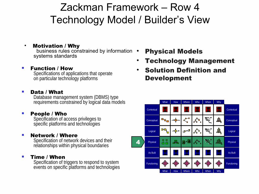
Zackman Framework – Row 4Technology Model / Builder’s View
Physical Models Technology Management Solution Definition and
Development
Motivation / Why business rules constrained by informationsystems standards
Function / HowSpecifications of applications that operateon particular technology platforms
Data / WhatDatabase management system (DBMS) typerequirements constrained by logical data models
People / WhoSpecification of access privileges tospecific platforms and technologies
Network / WhereSpecification of network devices and theirrelationships within physical boundaries
Time / WhenSpecification of triggers to respond to systemevents on specific platforms and technologies
4
Contextual
Conceptual
Logical
Physical
As Built
Functioning
Contextual
Conceptual
Logical
Physical
As Built
Functioning
Why
Why
Who
Who
When
When
Where
Where
What
What
How
How

Zackman Framework – Row 5As Built / Integrator’s View
As Built Configuration Management Deployment
Motivation/Why business rules constrained by specific technology standards
Function / HowPrograms coded to operate on specific technology platforms
Data / WhatData definitions constrained by physical data models
People / WhoAccess privileges coded to control access to specific platforms and technologies
Network / WhereNetwork devices configured to conform to node specifications
Time / WhenTiming definitions coded to sequence activities on specific platforms and technologies
5
Contextual
Conceptual
Logical
Physical
As Built
Functioning
Contextual
Conceptual
Logical
Physical
As Built
Functioning
Why
Why
Who
Who
When
When
Where
Where
What
What
How
How

Zackman Framework – Row 6Functioning Enterprise/User’s View
Functioning Enterprise Operations Management Evaluation
Motivation / WhyOperating characteristics of specific technologies constrained by standards
Function / HowFunctioning computer instructions
Data / WhatData values stored in actual databases
People / Who personnel and key stakeholders working within their roles and responsibilities
Network / WhereSending and receiving messages
Time / WhenTiming definitions operating to sequence activities 6
Contextual
Conceptual
Logical
Physical
Integrated
Functioning
Contextual
Conceptual
Logical
Physical
Integrated
Functioning
Why
Why
Who
Who
When
When
Where
Where
What
What
How
How
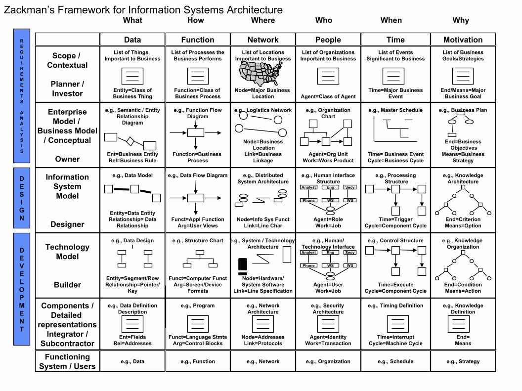
List of LocationsImportant to Business
Node=Major Business Location
What How Where Who When Why
Scope / Contextual
Planner /Investor
Data Function Network People Time Motivation
EnterpriseModel /
Business Model/ Conceptual
Owner
List of Things Important to Business
Entity=Class ofBusiness Thing
List of Processes theBusiness Performs
Function=Class of Business Process
List of OrganizationsImportant to Business
Agent=Class of Agent
List of EventsSignificant to Business
Time=Major BusinessEvent
List of BusinessGoals/Strategies
End/Means=MajorBusiness Goal
InformationSystemModel
Designer
TechnologyModel
Builder
Components /Detailed
representationsIntegrator /
Subcontractor
FunctioningSystem / Users
e.g., Semantic / EntityRelationship
Diagram
Ent=Business EntityRel=Business Rule
e.g., Semantic / EntityRelationship
Diagram
Ent=Business EntityRel=Business Rule
e.g., Function FlowDiagram
Function=Business Process
e.g., Data Model
Entity=Data EntityRelationship= Data
Relationship
e.g., Data
e.g., DistributedSystem Architecture
Node=Info Sys FunctLink=Line Char
e.g., Structure Chart
Funct=Computer FunctArg=Screen/Device
Formats
e.g., System / Technology Architecture
Node=Hardware/System Software
Link=Line Specification
e.g., Logistics Network
Node=Business Location
Link=BusinessLinkage
e.g., Program
Funct=Language StmtsArg=Control Blocks
e.g., Function
e.g., NetworkArchitecture
Node=AddressesLink=Protocols
e.g., Network
e.g., OrganizationChart
Agent=Org UnitWork=Work Product
e.g., Master Schedule
Time= Business EventCycle=Business Cycle
e.g., Business Plan
End=Business Objectives
Means=BusinessStrategy
e.g., Human InterfaceStructure
Agent=RoleWork=Job
e.g., Security Architecture
Agent=IdentityWork=Transaction
e.g., Organization
e.g., Processing Structure
Time=TriggerCycle=Component Cycle
e.g., Control Structure
Time=ExecuteCycle=Component Cycle
e.g., Timing Definition
Time=InterruptCycle=Machine Cycle
e.g., KnowledgeArchitecture
End=CriterionMeans=Option
e.g., Knowledge Organization
End=ConditionMeans=Action
e.g., KnowledgeDefinition
End=Means
e.g., Schedule e.g., Strategy
e.g., Data DefinitionDescription
Ent=FieldsRel=Addresses
e.g., Data Designl
Entity=Segment/RowRelationship=Pointer/
Key
e.g., Data Flow Diagram
Funct=Appl FunctionArg=User Views
REQUIREMENTS
ANALYSIS
DESIGN
DEVELOPMENT
Phone WS WS
Analyst Eng Secy
e.g., Human/Technology Interface
Agent=UserWork=Job
Analyst Eng Secy
Phone WS WS
Zackman’s Framework for Information Systems Architecture

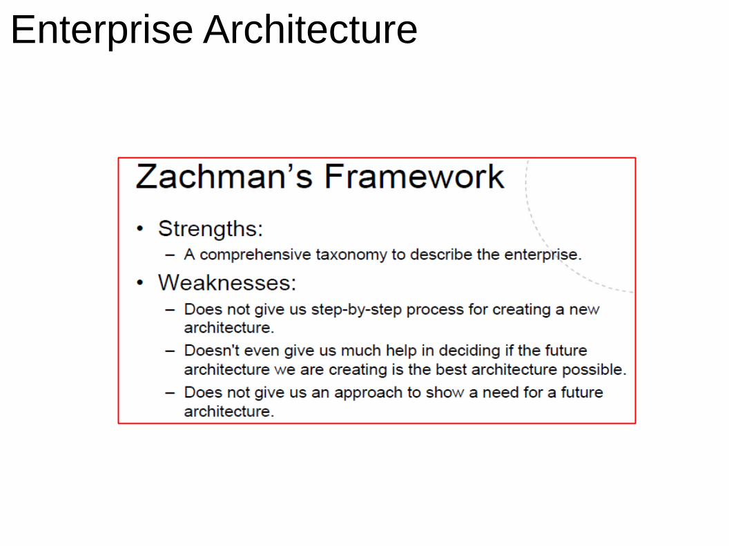
Conclusion The Zachman Framework is one of the renowned
frameworks that is comprehensive and simple to understand.
Some drawbacks of this framework for the modeling of information systems may be summarized in the following.
− ZF has large amount of documentations (in detailed texts, modeling diagrams and charts) for each of ZF's cell (for each of 36 cells).
− ZF doesn't have any consideration to As-Is of the Information Systems.
ZF considers only establishing of new architectures for information systems of enterprises without considering the previous systems (As-Is status of systems). Whereas, the most enterprises information systems need to consider to As-Is status before implementing it.

Software ArchitectureZackman and TOGAF Frameworks
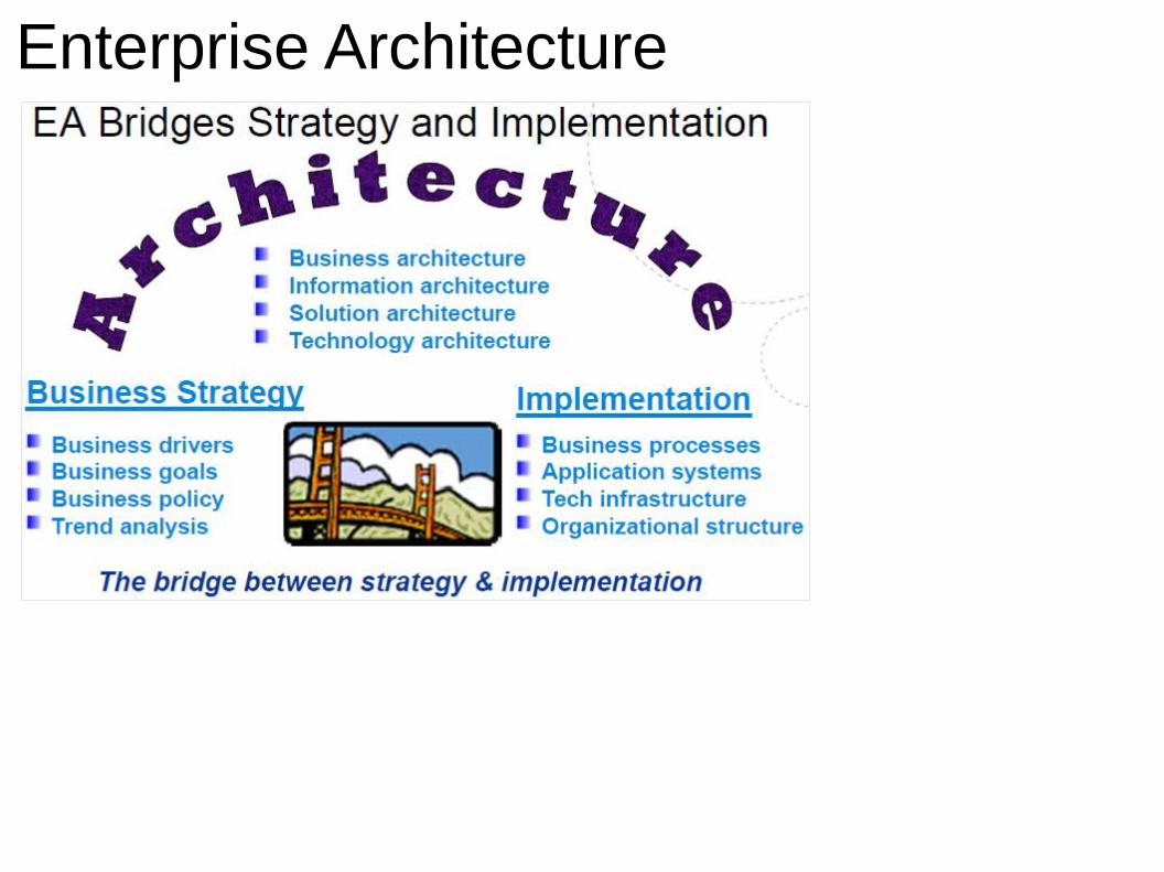
Enterprise Architecture
Enterprise Architecture
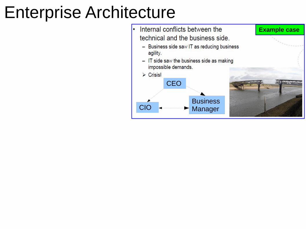
Enterprise ArchitectureExample case
CEO
Business ManagerCIO
Enterprise Architecture

Enterprise Architecture
Enterprise Architecture

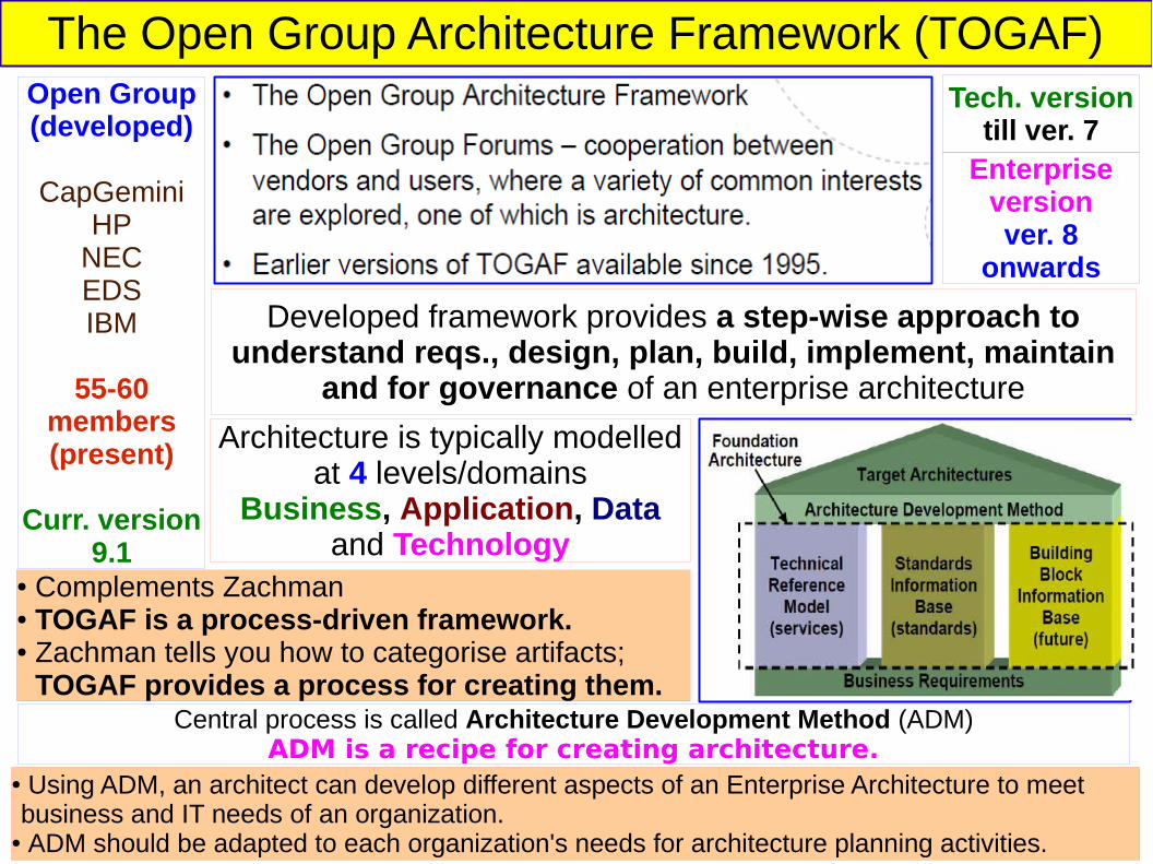
The Open Group Architecture Framework (TOGAF)Open Group(developed)
CapGeminiHP
NECEDSIBM
55-60 members (present)
Curr. version 9.1
Developed framework provides a step-wise approach to understand reqs., design, plan, build, implement, maintain
and for governance of an enterprise architecture
Tech. versiontill ver. 7
Enterprise versionver. 8
onwards
Architecture is typically modelled at 4 levels/domains
Business, Application, Data and Technology
● Complements Zachman● TOGAF is a process-driven framework.● Zachman tells you how to categorise artifacts; TOGAF provides a process for creating them.
● Using ADM, an architect can develop different aspects of an Enterprise Architecture to meet business and IT needs of an organization.
● ADM should be adapted to each organization's needs for architecture planning activities.
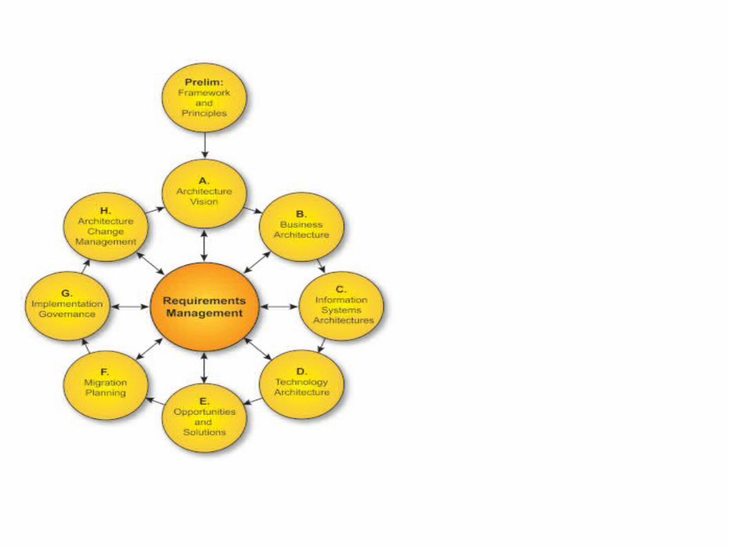
Central process is called Architecture Development Method (ADM)ADM is a recipe for creating architecture.
The Open Group Architecture Framework (TOGAF)Open Group(developed)
CapGeminiHP
NECEDSIBM
55-60 members (present)
Curr. version 9.1
Developed framework provides a step-wise approach to understand reqs., design, plan, build, implement, maintain
and for governance of an enterprise architecture
Tech. versiontill ver. 7
Enterprise versionver. 8
onwards
Architecture is typically modelled at 4 levels/domains
Business, Application, Data and Technology
● Complements Zachman● TOGAF is a process-driven framework.● Zachman tells you how to categorise artifacts; TOGAF provides a process for creating them.
● Using ADM, an architect can develop different aspects of an Enterprise Architecture to meet business and IT needs of an organization.
● ADM should be adapted to each organization's needs for architecture planning activities.
Central process is called Architecture Development Method (ADM)ADM is a recipe for creating architecture.

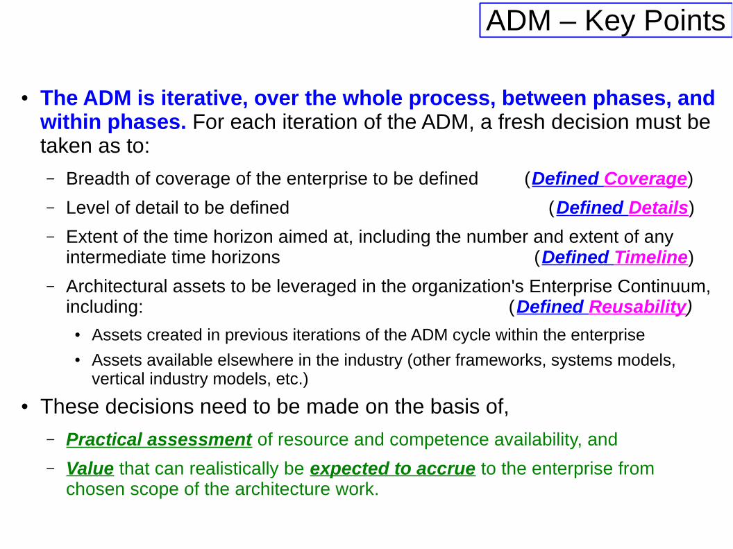
ADM – Key Points
● The ADM is iterative, over the whole process, between phases, and within phases. For each iteration of the ADM, a fresh decision must be taken as to:
– Breadth of coverage of the enterprise to be defined (Defined Coverage)
– Level of detail to be defined (Defined Details)
– Extent of the time horizon aimed at, including the number and extent of any intermediate time horizons (Defined Timeline)
– Architectural assets to be leveraged in the organization's Enterprise Continuum, including: (Defined Reusability)
● Assets created in previous iterations of the ADM cycle within the enterprise● Assets available elsewhere in the industry (other frameworks, systems models,
vertical industry models, etc.)
● These decisions need to be made on the basis of,
– Practical assessment of resource and competence availability, and
– Value that can realistically be expected to accrue to the enterprise from chosen scope of the architecture work.
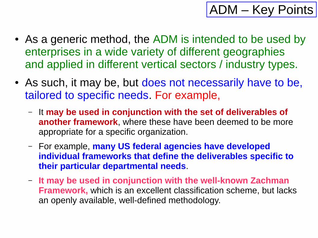
● As a generic method, the ADM is intended to be used by enterprises in a wide variety of different geographies and applied in different vertical sectors / industry types.
● As such, it may be, but does not necessarily have to be, tailored to specific needs. For example,– It may be used in conjunction with the set of deliverables of
another framework, where these have been deemed to be more appropriate for a specific organization.
– For example, many US federal agencies have developed individual frameworks that define the deliverables specific to their particular departmental needs.
– It may be used in conjunction with the well-known Zachman Framework, which is an excellent classification scheme, but lacks an openly available, well-defined methodology.
ADM – Key Points
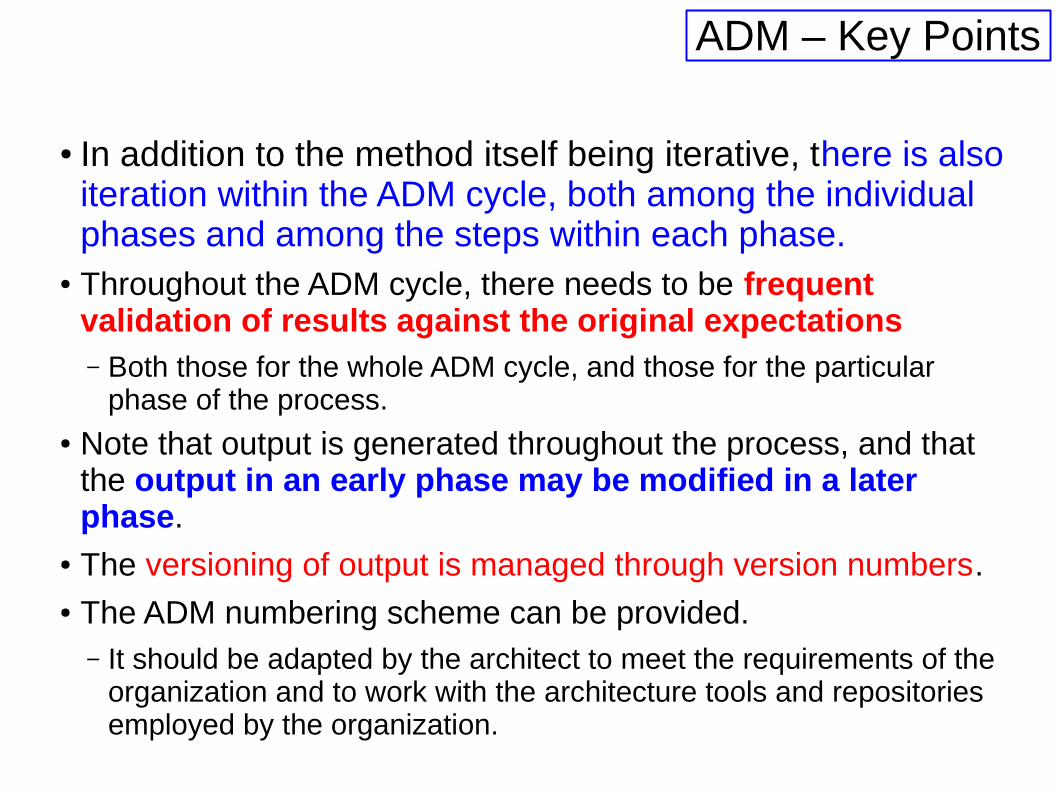
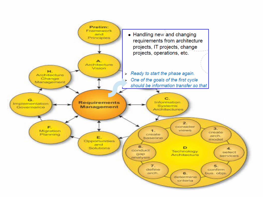
● In addition to the method itself being iterative, there is also iteration within the ADM cycle, both among the individual phases and among the steps within each phase.
● Throughout the ADM cycle, there needs to be frequent validation of results against the original expectations– Both those for the whole ADM cycle, and those for the particular
phase of the process.● Note that output is generated throughout the process, and that
the output in an early phase may be modified in a later phase.
● The versioning of output is managed through version numbers. ● The ADM numbering scheme can be provided.
– It should be adapted by the architect to meet the requirements of the organization and to work with the architecture tools and repositories employed by the organization.
ADM – Key Points


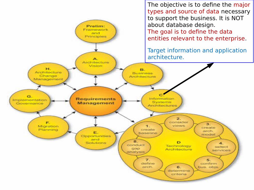
The objective is to define the major types and source of data necessary to support the business. It is NOT about database design. The goal is to define the dataentities relevant to the enterprise.
Target information and applicationarchitecture.


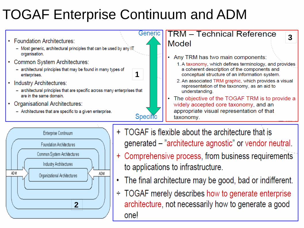
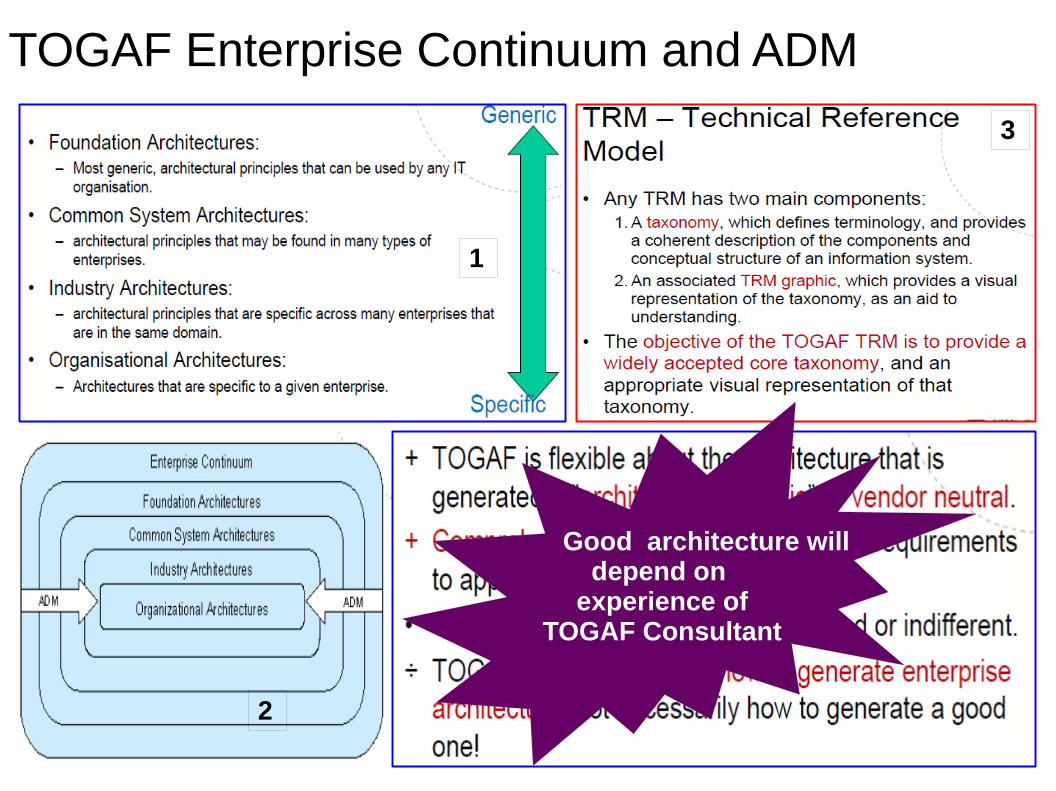
Enterprise Continuum
● TOGAF views the Enterprise Architecture as a
continuum of architectures, ranging from the highly generic to the highly specific.
● It views the process of creating a specific enterprise architecture as moving from the generic to the specific.
● TOGAF’s ADM provides a process for driving this movement from the generic to the specific.
TOGAF Enterprise Continuum and ADM
1
2
3
TOGAF Enterprise Continuum and ADM
1
2
3
Good architecture willdepend on
experience ofTOGAF Consultant

Reference Model for Open Distributed Processing (RM-ODP)
● It provides a framework for specification of distributed computing systems.
● It is based on,
– current practices in distributed processing community, and
– use of formal description techniques for specification of architectures.
● It combines the concepts of open systems (supplier independent) in specifying distributed systems.
● Found to be very useful and widely adopted.
● RM-ODP framework is the origin of the famous 4+1 view model.
● RM-ODP guides the modeling process of systems architecture
– Gives five view points that are considered essential.
– Enterprise viewpoint, Information viewpoint, Computational viewpoint, Engineering viewpoint, and Technology viewpoint.

Summary● TOGAF provides a set of foundation architectures to aid architects
understand the present and future needs of the architecture
● In enterprise version, TOGAF was expanded to cover business, application and information aspects of EA.
– The process of these is not as fully developed as the process for the technical architecture
– The relationships between different aspects of architecture are also not completely captured and documented.
● One main criticism
– It is concerned with the process of developing artefacts.
– There is no emphasis on the quality or the format of the artefacts.