theme 3 current energy technology-englishd284f45nftegze.cloudfront.net/hideakioh/theme 3 current...
TRANSCRIPT

Theme 3: Current Energy Technology
Sopheak REY
ODA-UNESCO Project for Promotion of Energy Science Education for Sustainable Development in Cambodia
Phnom Penh, February 18-21, 2014
Industrial and Mechanical Engineering Department,
Institute of Technology of Cambodia

Objective the Scheme 2
• Understand the current energy technologies including conventional and clean energy technologies
• Merit, demerit and process of working of each technology is explained
• Current applicable energy technology that are using in Cambodia and in the region

Theme 3: Current Energy Technology 3
Contents
Part 1. Traditional energy technology1.1 Introduction1.2 Conventional energy technologies1.3 Thermal power plant technologies
Part 2. Technology of reducing gaseousemissions2.1 Clean coal technologies2.2 Nuclear power plant technologies
1.1 Introduction 4
• Energy conversion
• Current energy technology
• Existing CCT and Potential
There are brief introduction about:
Energy conversions/coal 5
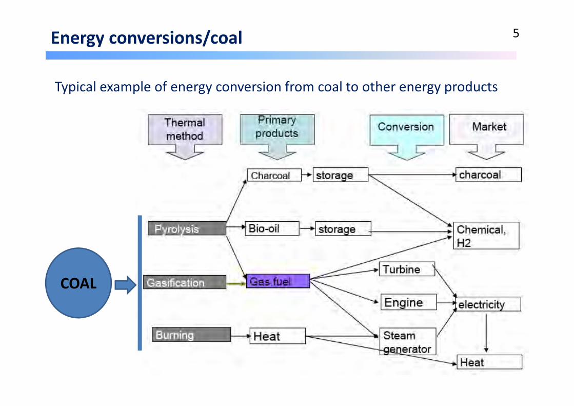
Typical example of energy conversion from coal to other energy products
COAL
1.1 Introduction 6
• Energy conversion
• Current energy technology
• Existing CCT and Potential
There are brief introduction about:

Current energy technologies 7
There are 2 types of fluidized bed combustions which can be used for various kind of coals (lignite, anthracite and bituminous) :
Pulverized Fuel Combustion (PFC) (for high quality coals such as bituminous and anthracite)
Fluidized Bed Combustion (FBC) (for low quality coal such as lignite and biomass fuel)
Other types of technology that are currently used in power plant such as :
Gas Turbine Power plants (GTP)
Combined Cycle Power Plants (CCPPs) (Combine Gas and Steam Turbine)

1.1 Introduction 8
• Energy conversion
• Current energy technology
• Existing CCT and Potential
There are brief introduction about:

Existing CCT and Potential 9
The Clean Coal Technology includes:
1‐ The reduction of exhaust gas emission: Reduced By Stack Gas Treatment–removal of 99%
particulates, 97% SOx possible
Emit low CO2, NOx
2‐ The improve of combustion by:
Advanced Pulverized Fuel Combustion (PFC)
Advanced Fluidized Bed Combustion (FBC)
Integrated Gasification Combine Cycle (IGCC)
Hybrid and Advanced Systems
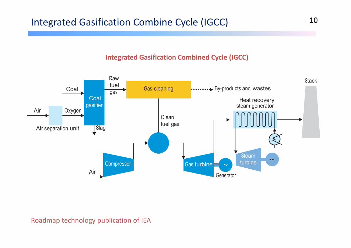
Integrated Gasification Combine Cycle (IGCC) 10
Air
Coal Oxygen
Coal
gasifier
Raw fuel gas
Gas cleaning
Clean
By-products and wastes
Heat recovery steam generator
Stack
Air separation unit
Slag fuel gas
Air
Compressor Gas turbine
Generator
Steam turbine
Roadmap technology publication of IEA
Integrated Gasification Combined Cycle (IGCC)

1.2 Conventional energy technologies 11
• Fuels
• Diesel engine basics
• Basic principles (Working cycles)
• Large hydro‐energy technology
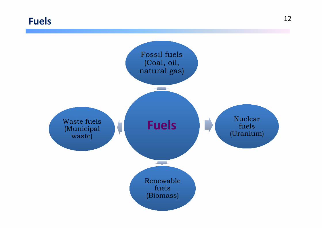
Fuels 12
FuelsFuels
Fossil fuels (Coal, oil,
natural gas)
Fossil fuels (Coal, oil,
natural gas)
Nuclear fuels
(Uranium)
Nuclear fuels
(Uranium)
Renewable fuels
(Biomass)
Renewable fuels
(Biomass)
Waste fuels (Municipal
waste)
Waste fuels (Municipal
waste)

Fuels 13

Fuels/oil 14
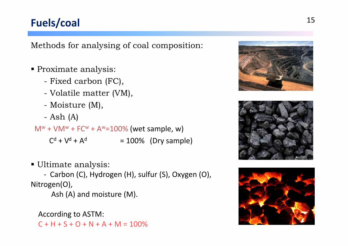
Fuels/coal 15
Methods for analysing of coal composition:
Proximate analysis:- Fixed carbon (FC), - Volatile matter (VM), - Moisture (M), - Ash (A)
Mw + VMw + FCw + Aw=100% (wet sample, w)Cd + Vd + Ad = 100% (Dry sample)
Ultimate analysis:‐ Carbon (C), Hydrogen (H), sulfur (S), Oxygen (O),
Nitrogen(O), Ash (A) and moisture (M).
According to ASTM:C + H + S + O + N + A + M = 100%
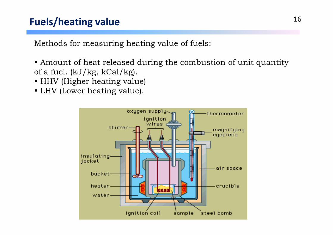
Fuels/heating value 16
Methods for measuring heating value of fuels:
Amount of heat released during the combustion of unit quantity of a fuel. (kJ/kg, kCal/kg). HHV (Higher heating value) LHV (Lower heating value).
1.2 Conventional energy technologies 17
• Fuels
• Diesel engine basics
• Basic principles (Working cycles)
• Large hydro‐energy technology

1.2 Diesel engine basics 18
Operation/condition Engine system/Operating cycle

1.2 Diesel engine basics/operation 19
Advantage of diesel engine- Easy to design and install- Available in standard capacities- Can respond to load change without much difficulty- Less standby loss- Occupy less space- Can be started and stopped quickly- Require less cooling water- Less capital cost- Less operating and supervising staffs - High efficiency from fuel to electricity- Less civil engineering work- Can be located near to load center- No ash handling problem- Easier lubrication system
Advantage of diesel engine- High operating cost
- High maintenance and lubrication cost- Capacity is restricted, can not be of very big size- Noise problem- Can not supply overload- Unhygienic emissions
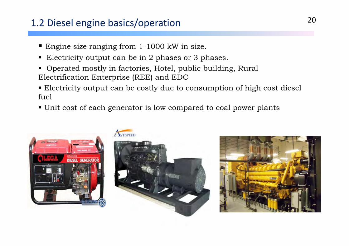
1.2 Diesel engine basics/operation 20
Engine size ranging from 1-1000 kW in size. Electricity output can be in 2 phases or 3 phases. Operated mostly in factories, Hotel, public building, Rural Electrification Enterprise (REE) and EDC Electricity output can be costly due to consumption of high cost diesel fuel Unit cost of each generator is low compared to coal power plants

1.2 Engine system/operating cycle 21
Basic components of diesel engine
Working cycle of diesel engineWorking stroke of diesel engine

1.2 Conventional energy technologies 22
• Fuels
• Diesel engine basics
• Basic principles (Working cycles)
• Large hydro‐energy technology
Basic principles (working cycle) 23
There are 3 working cycles that are mostly in use in power plants such as:
Rankine cycle (for steam turbine)
Brayton cycle (for gas turbine)
Combined cycle (for gas and steam turbines)

Basic principles (working cycle)/Rankine cycle 24
A simple steam plant representing Ranking cycle
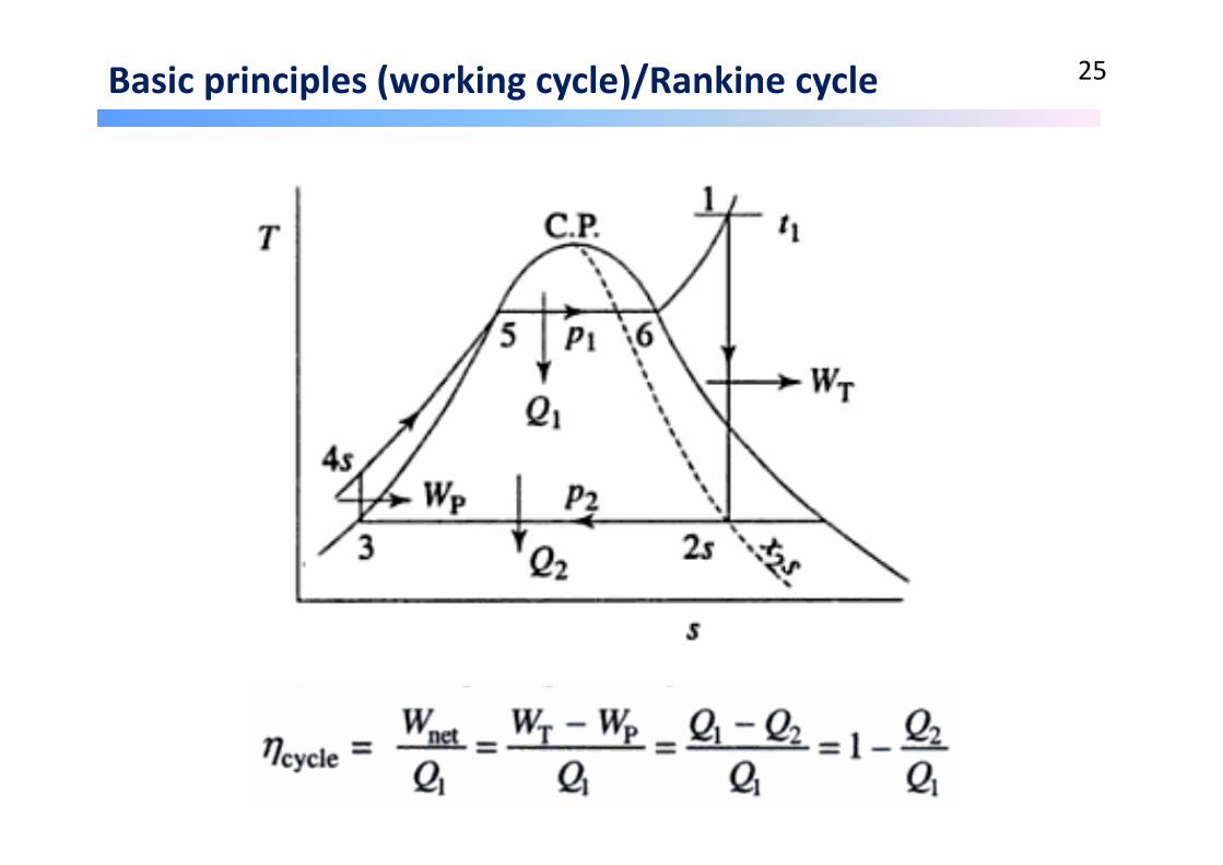
Basic principles (working cycle)/Rankine cycle 25
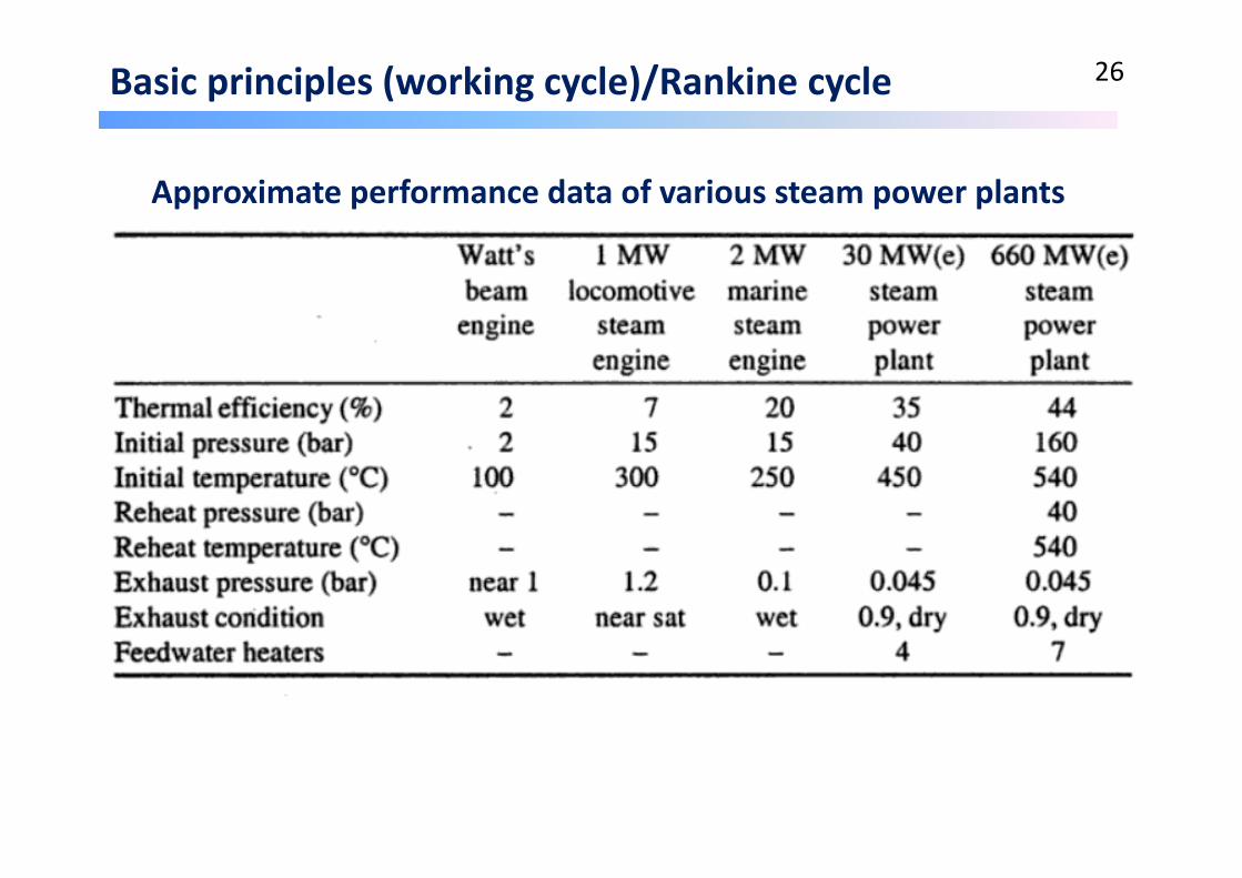
Basic principles (working cycle)/Rankine cycle 26
Approximate performance data of various steam power plants

Basic principles (working cycle)/Brayton cycle 27
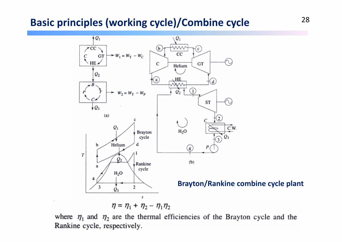
Basic principles (working cycle)/Combine cycle 28
Brayton/Rankine combine cycle plant

Basic principles (working cycle)/Combine cycle 29
A typical efficiency of combined cycle

Basic principles (working cycle)/Combine cycle 30
Comparison of steam power plant before and after repowering to a combine cycle plant
Merit: The advantage of combine cycle is the high overall thermalefficiency. It means that it reduces the operational cost (fuelcost)
Demerit: High construction cost

1.2 Conventional energy technologies 31
• Fuels
• Diesel engine basics
• Basic principles (Working cycles)
• Large hydro‐energy technology
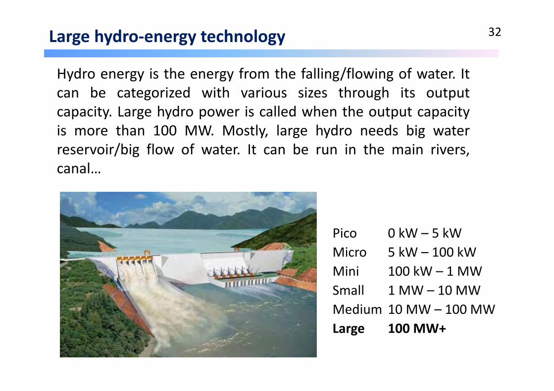
Large hydro‐energy technology 32
Pico 0 kW – 5 kWMicro 5 kW – 100 kWMini 100 kW – 1 MWSmall 1 MW – 10 MWMedium 10 MW – 100 MWLarge 100 MW+
Hydro energy is the energy from the falling/flowing of water. Itcan be categorized with various sizes through its outputcapacity. Large hydro power is called when the output capacityis more than 100 MW. Mostly, large hydro needs big waterreservoir/big flow of water. It can be run in the main rivers,canal…

Large hydro components 33
Main components of large hydro‐electric power generation are: Reservoir, Dam, Sluice gates, Penstock, Power house (Turbine, Generator, Power house), Spill ways…..

Merits of Large hydro power 34
1. Fuel is not burned so there is minimal pollution
2. Water to run the power plant is provided free by nature
3. Hydropower plays a major role in reducing greenhouse gas emissions
4. Relatively low operations and maintenance costs
5. The technology is reliable and proven over time
6. It's renewable ‐ rainfall renews the water in the reservoir, so the fuel is almost always there
Demerits of Large hydro power 35
1. High investment costs
2. Hydrology dependent (precipitation)
3. In some cases, inundation of land and wildlife habitat
4. In some cases, loss or modification of fish habitat
5. Fish entrainment or passage restriction
6. In some cases, changes in reservoir and stream water quality
7. In some cases, displacement of local populations
8. Large hydro power is not sustainable.

1.3 Thermal power plant technologies 36
• Coal preparation system
• Coal combustion technologies
• Steam turbine
• Gas turbine
• Waste heat recovery
• Co‐generation

Coal preparation 37
Ultr
afin
e
SieveBends
Dense Media
Cyclone
BasketCentrifuge
s
Dense Media Vessel
DewateringScreens
Raw CoalScreens
Coal Spirals Screen-BowlCentrifuges
ClassifyingCyclones
Med
ium
Solid-Solid Solid-LiquidSize-Size
Coa
rse
Fine
Froth Flotation Disc Filter
In pulverized coal combustion, the coal is prepared through various mechanical processes to get fine size and in various states. Following diagram shows those preparation processes:

1.3 Thermal power plant technologies 38
• Coal preparation system
• Coal combustion technologies
• Steam turbine
• Gas turbine
• Waste heat recovery
• Co‐generation
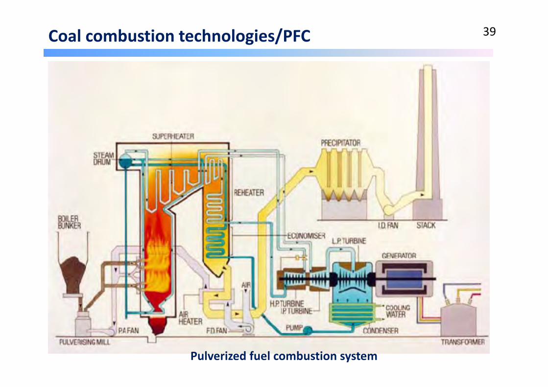
Coal combustion technologies/PFC 39
Pulverized fuel combustion system

Coal combustion technologies/FBC 40
1.3 Thermal power plant technologies 41
• Coal preparation system
• Coal combustion technologies
• Steam turbine
• Gas turbine
• Waste heat recovery
• Co‐generation

Steam turbine 42
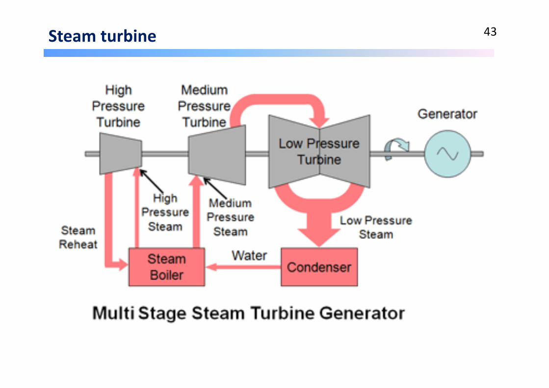
Steam turbine 43

1.3 Thermal power plant technologies 44
• Coal preparation system
• Coal combustion technologies
• Steam turbine
• Gas turbine
• Waste heat recovery
• Co‐generation

Gas turbine 45

Gas turbine 46
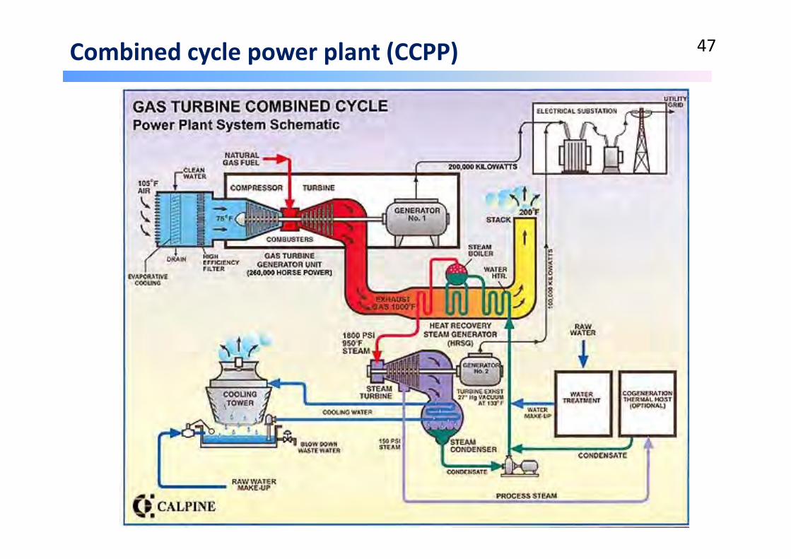
Combined cycle power plant (CCPP) 47

1.3 Thermal power plant technologies 48
• Coal preparation system
• Coal combustion technologies
• Steam turbine
• Gas turbine
• Waste heat recovery
• Co‐generation
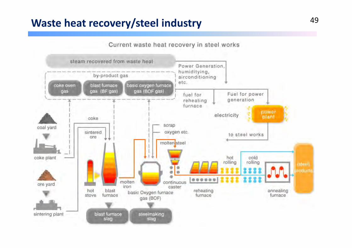
Waste heat recovery/steel industry 49

Waste heat recovery/Cement plant 50

1.3 Thermal power plant technologies 51
• Coal preparation system
• Coal combustion technologies
• Steam turbine
• Gas turbine
• Waste heat recovery
• Co‐generation
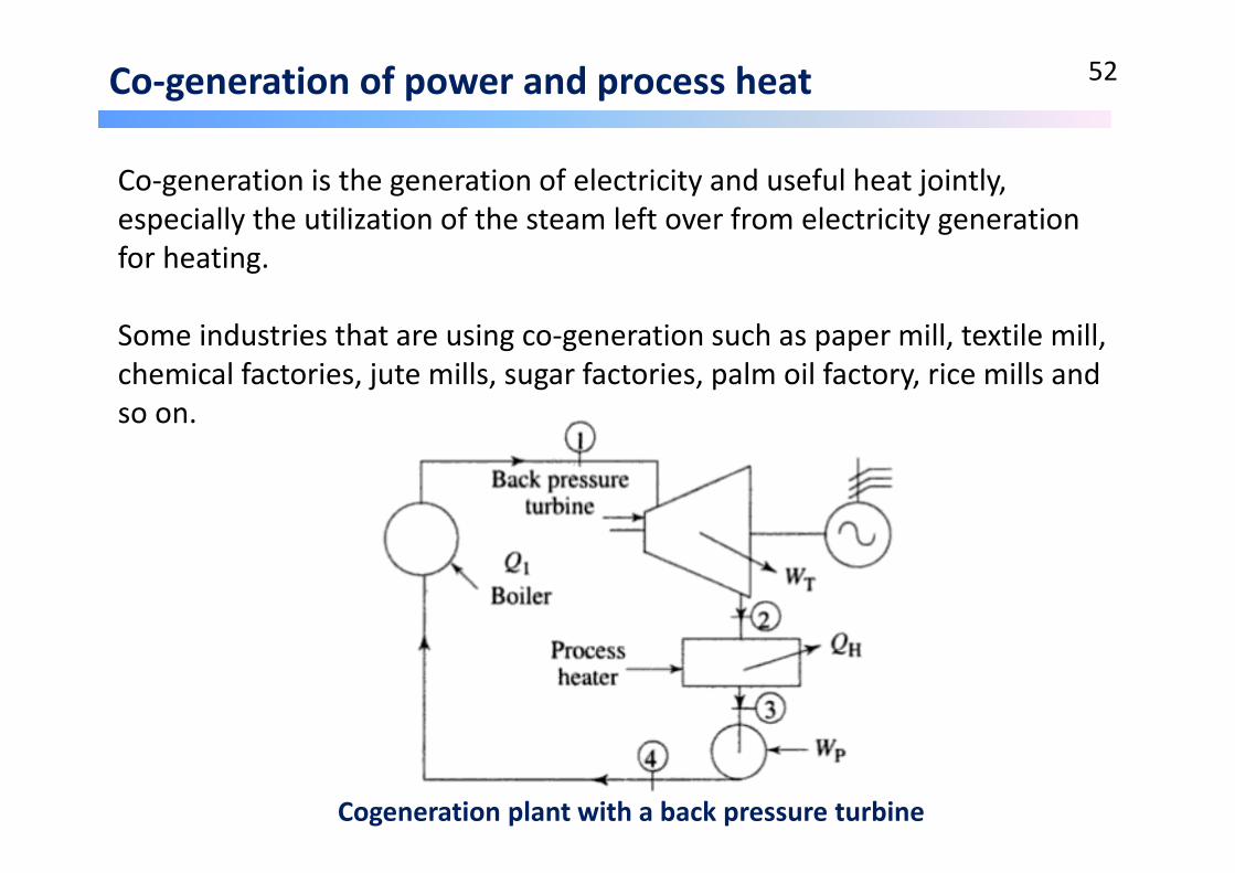
Co‐generation of power and process heat 52
Co‐generation is the generation of electricity and useful heat jointly, especially the utilization of the steam left over from electricity generation for heating.
Some industries that are using co‐generation such as paper mill, textile mill, chemical factories, jute mills, sugar factories, palm oil factory, rice mills and so on.
Cogeneration plant with a back pressure turbine

Co‐generation of power and process heat/Merits 53
In the co‐generation or combine heat and power (CHP) has the advantages such as:
‐ It does not need a cooling system which reduce the cost of power plant
‐ It increases the overall thermal efficiency which reduce the cost of operation (fuel cost)

Co‐generation of power and process heat 54
Schematic diagram of co‐generation

Co‐generation of power and process heat 55
Operating data of a combined cycle cogeneration plant

2.1 Clean coal technology 56
Clean coal technology is a collection of technologies being developed to mitigate the environmental impact of coal energy generation. Gaseous emissions generated by the thermal decomposition of the coal include SOx, NOx, CO2, and other PMs are reduced/removed through clean coal technologies.
Some of the techniques that would be used to accomplish this include chemically washing minerals and impurities from the coal, gasification and IGCC, treating the flue gases with steam to remove sulfur dioxide, carbon capture and storagetechnologies to capture the carbon dioxide from the flue gas and dewatering lower rank coals (brown coals) to improve the calorific value, and thus the efficiency of the conversion into electricity.
Some of those clean coal technologies will be discussed in detail such as:
• NOx generation and reduction
• SO2 reduction
• Carbon capture and storage
2.1 Clean coal technology 57
• NOx generation and reduction
• SO2 reduction
• Carbon capture and storage
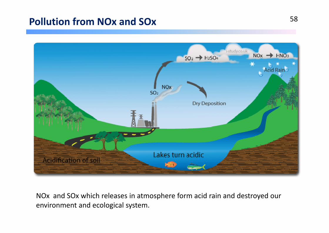
Pollution from NOx and SOx 58
NOx and SOx which releases in atmosphere form acid rain and destroyed our environment and ecological system.
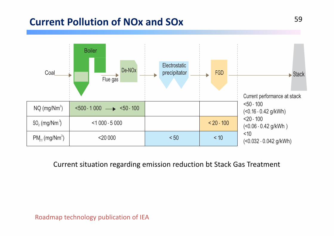
Current Pollution of NOx and SOx 59
x
2.5
Boiler
Coal Flue gas
De-NOx
Electrostatic precipitator
FGD
Stack
NO (mg/Nm3)
3
<500 - 1 000
<50 - 100
Current performance at stack <50 - 100 (<0.16 - 0.42 g/kWh) <20 - 100
SO2 (mg/Nm )
PM (mg/Nm3)
<1 000 - 5 000
<20 000
< 20 - 100 < 50 < 10
(<0.06 - 0.42 g/kWh ) <10 (<0.032 - 0.042 g/kWh)
Current situation regarding emission reduction bt Stack Gas Treatment
Roadmap technology publication of IEA

N2 in Coal 60
Name Structure ~ Relative amount
Stability
Pyridine1 15-40% More stable
Pyrrole1 60% Less stable
Aromatic amines
6-10% Stable
1Including structures made up of 2-5 fused aromatic rings.

NOx Formation Mechanism 61
‐ Thermal NO
‐ Prompt NO
‐ Fuel NO: volatiles‐NO and char‐NO
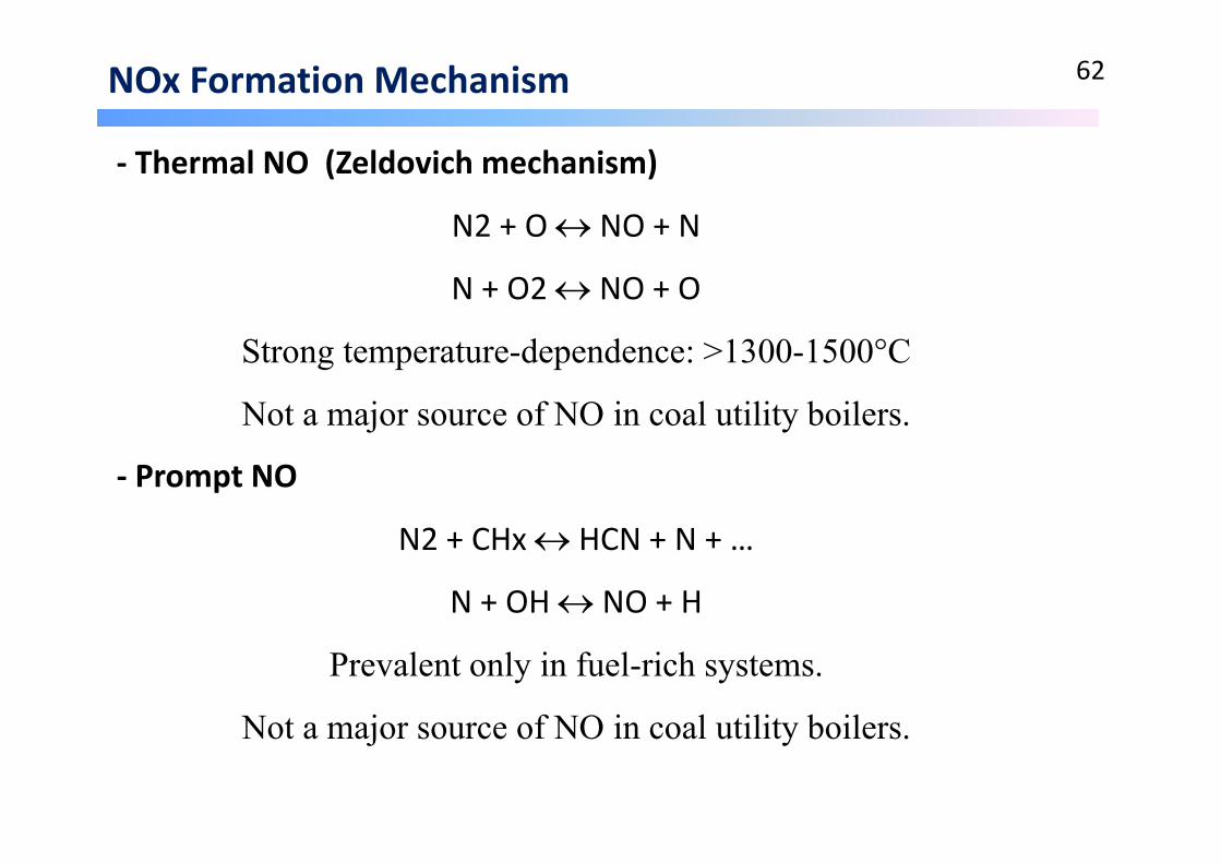
NOx Formation Mechanism 62
‐ Thermal NO (Zeldovich mechanism)
N2 + O NO + N
N + O2 NO + O
Strong temperature-dependence: >1300-1500°C
Not a major source of NO in coal utility boilers.
‐ Prompt NO
N2 + CHx HCN + N + …
N + OH NO + H
Prevalent only in fuel-rich systems.
Not a major source of NO in coal utility boilers.

NOx Formation Mechanism 63
‐ Fuel NO (‐N in volatiles)
Fuel-N HCN/NH3
The major source of NO in coal utility boilers (>80%).
‐ Char NO (‐N in the char)
volatiles(formation)
(destruction)HCN/NH3 + O2
N2
NONO + HCN/NH3
Char-N + ½O2 NO
Char-C + NO ½N2 + Char(O)
(formation)
(destruction)
[char-NO = ~25%] < [volatiles-NO = ~75%]
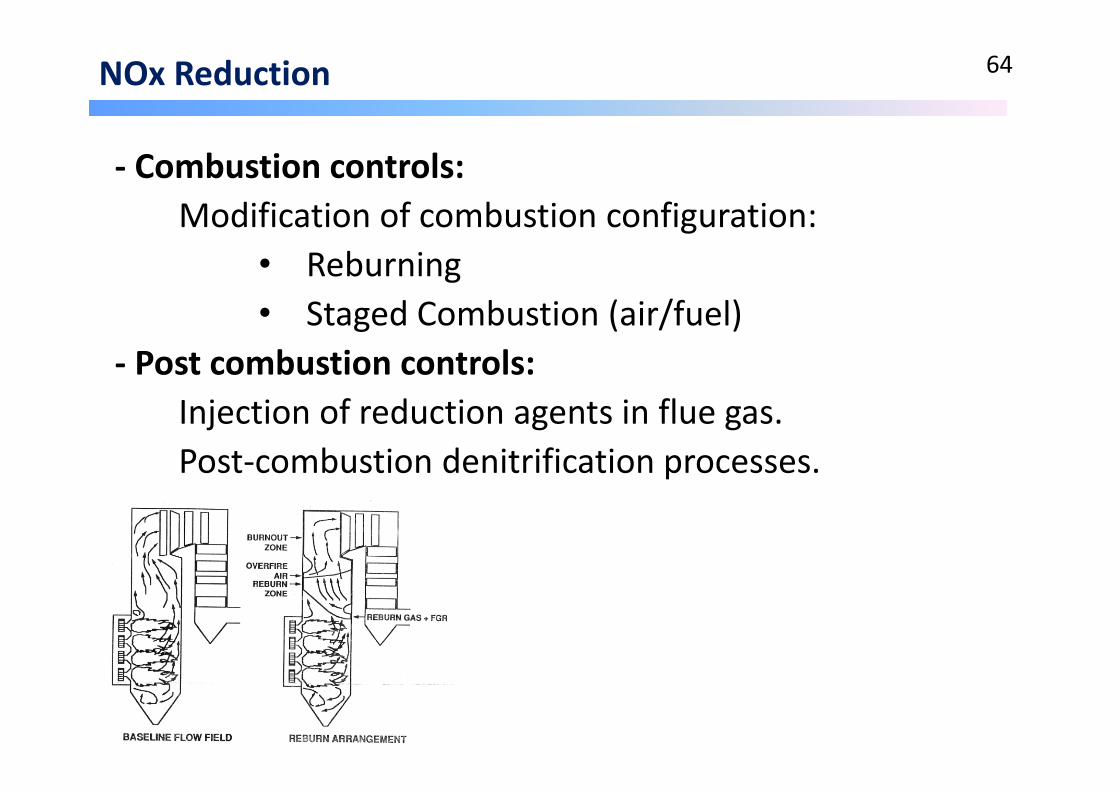
NOx Reduction 64
‐ Combustion controls:Modification of combustion configuration:
• Reburning• Staged Combustion (air/fuel)
‐ Post combustion controls:Injection of reduction agents in flue gas.Post‐combustion denitrification processes.
2.1 Clean coal technology 65
• NOx generation and reduction
• SO2 reduction
• Carbon capture and storage
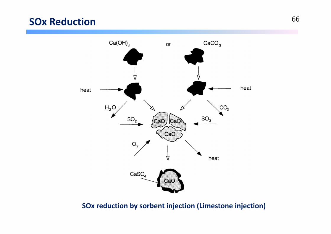
SOx Reduction 66
SOx reduction by sorbent injection (Limestone injection)

SOx Reduction 67
SOx reduction by sorbent injection
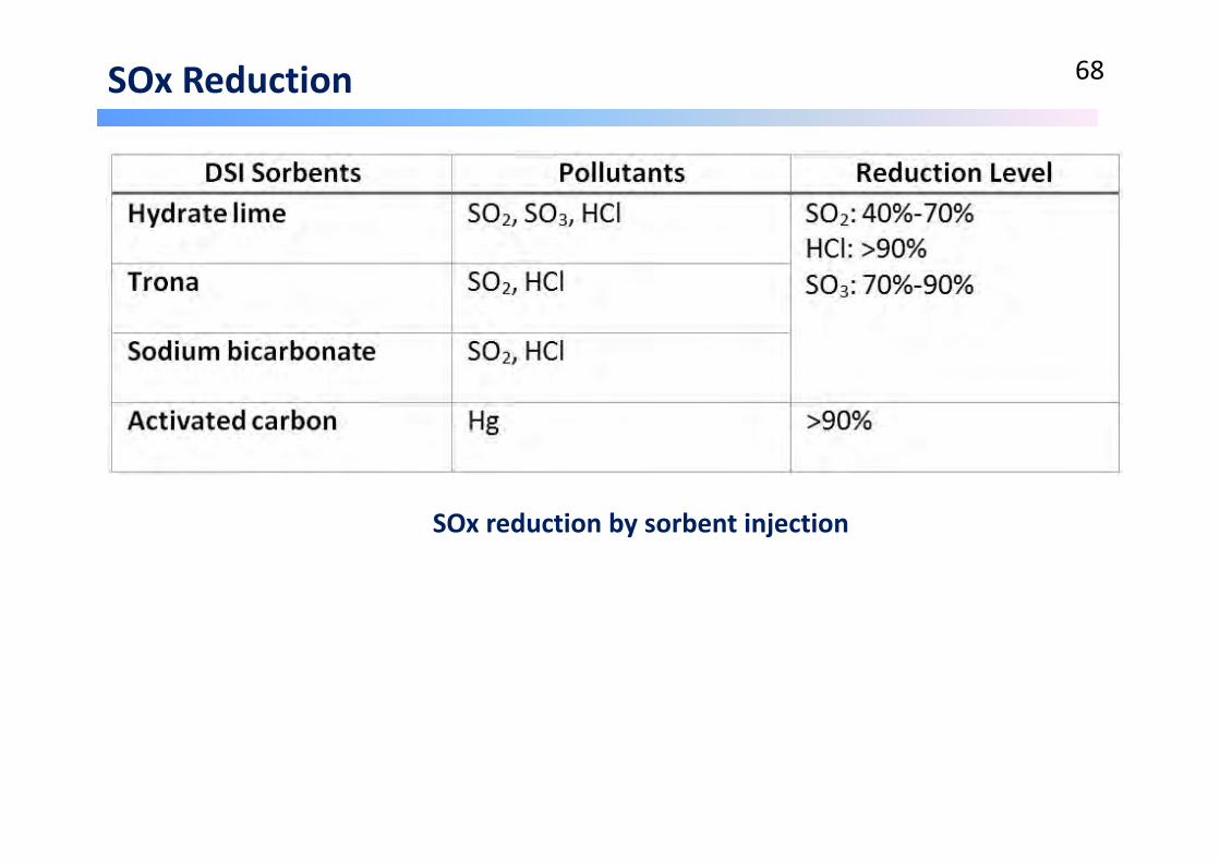
SOx Reduction 68
SOx reduction by sorbent injection

NOx and SOx Reduction 69

NOx and SOx Reduction 70
0
1
2
3
4
SOx NOx SOx NOx
France in 2005 Japan in 2010
(g/k
Wh)
SourceFrance: OECD Environmental Data Compendium 2006/2007Japan: Federation of Electric Power Companies of Japan
2.1 Clean coal technology 71
• NOx generation and reduction
• SO2 reduction
• Carbon capture and storage

CO2 emission 72
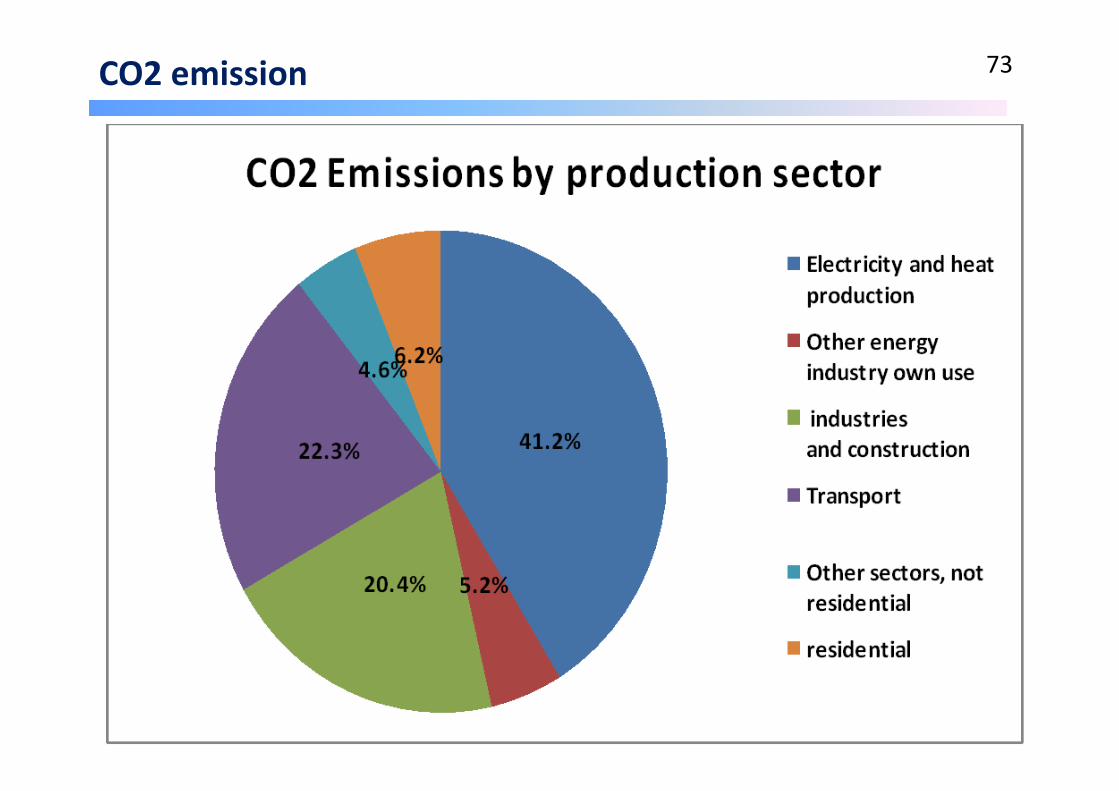
CO2 emission 73
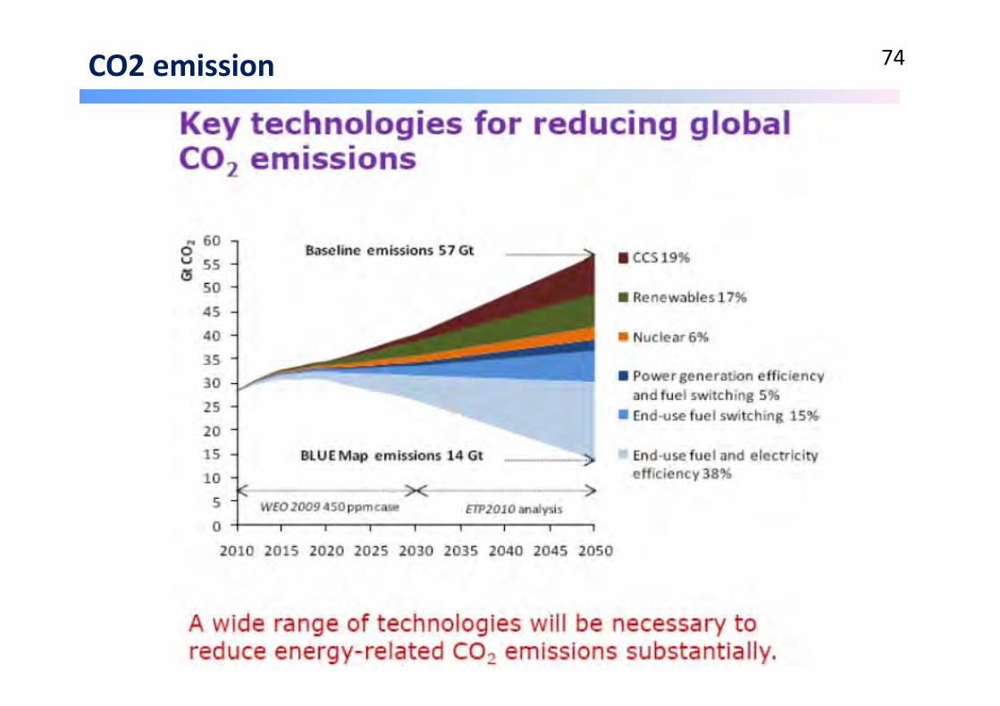
CO2 emission 74

Carbon sequestration 75
• Mitigates the contribution of fossil fuels into the atmosphere.
• Large sources are targeted, e.g coal power stations.
• Instead CO2 is captured and stored underground so it can’t enter the atmosphere.

CO2 Capture and Storage (CCS) 76
Fuels
Processes
Storage options

CO2 Capture and Storage (CCS) 77
1996 1999 2001
Example: Seismic monitoring at Sleipner
Measurement, Monitoring and Verification (MM&V) of CO2 storage

Ocean storage of CO2 78

2.2 Nuclear power plant technology 79
• Current situation of nuclear energy
• Working process and merits of nuclear power plant
• Radioactive level and dosages

Current situation of nuclear energy 80

Current situation of nuclear energy 81
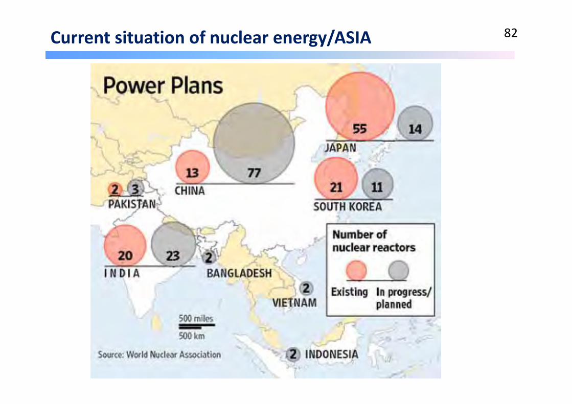
Current situation of nuclear energy/ASIA 82
2.2 Nuclear power plant technology 83
• Current situation of nuclear energy
• Working process and merits of nuclear power plant
• Radioactive level and dosages
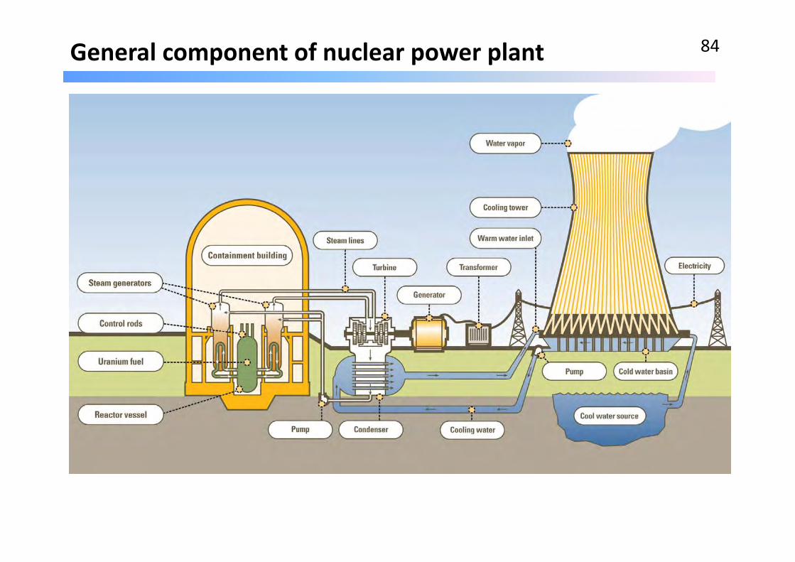
General component of nuclear power plant 84
Merit of Nuclear Power Plant 85
• Fission is the most energy for the least fuel with current technology.
• Uranium is readily available, very common in the earth's crust (about the same as tin)
• Economical ‐ operating cost about the same as coal, fuel cost is a much smaller percentage of the total, therefore less susceptible to price fluctuations.
• Reliable ‐ Nuclear power plants have very high capacity factors. No combustion, no CO, CO2 or SO2 released.
• Creates high paying, skilled jobs and fantastic safety record. .
• Reduce dependence on foreign oil/ fuel. Increase national energy security (a fill in of nuclear can be used up to 6 months)
• High temperature reactors could produce Hydrogen as well as electricity.
• A unit of nuclear power unit (1GW) can supply the whole Cambodia at present.
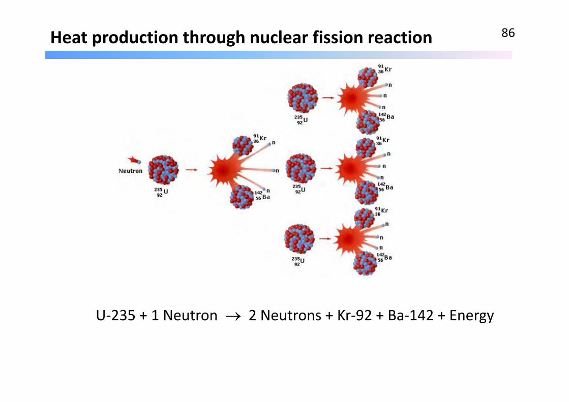
Heat production through nuclear fission reaction 86
U‐235 + 1 Neutron 2 Neutrons + Kr‐92 + Ba‐142 + Energy
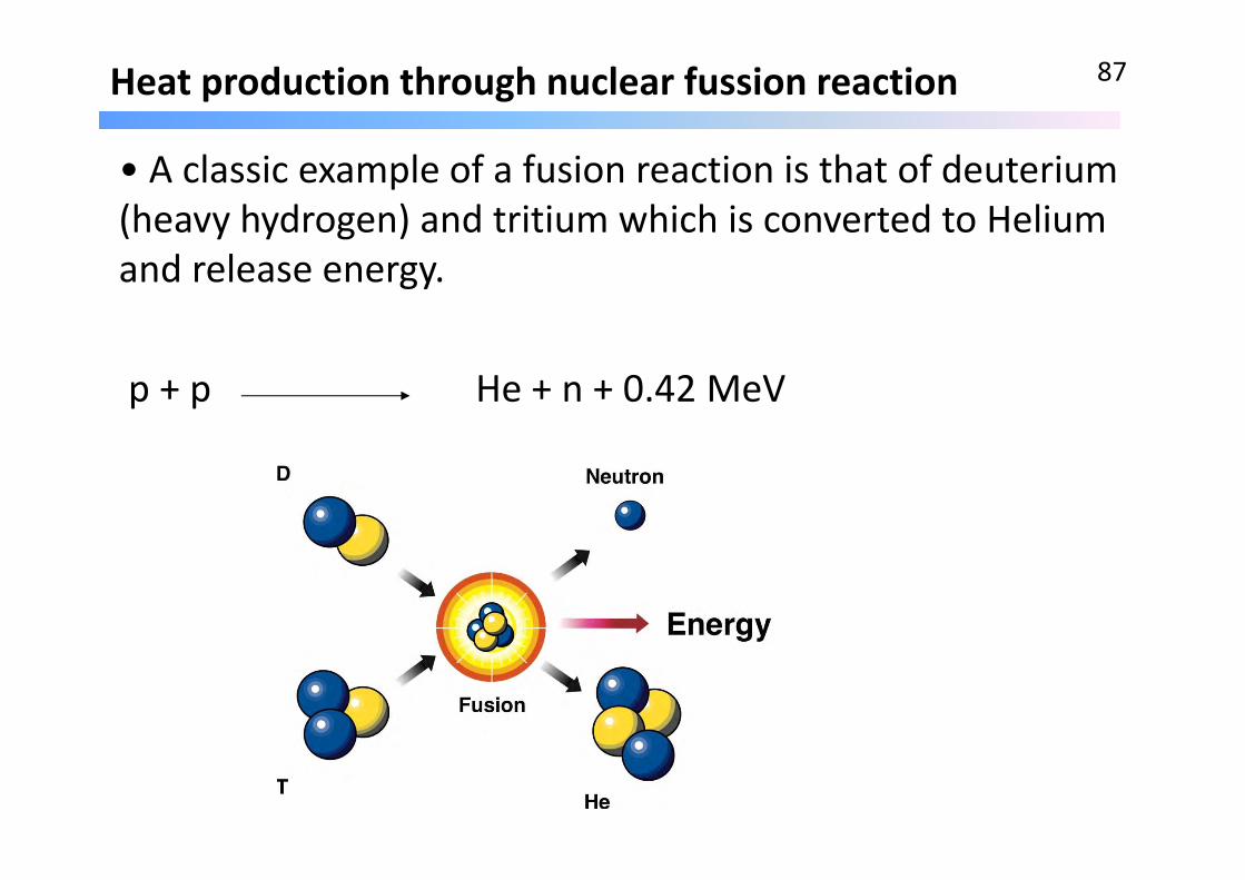
Heat production through nuclear fussion reaction 87
• A classic example of a fusion reaction is that of deuterium (heavy hydrogen) and tritium which is converted to Helium and release energy.
p + p He + n + 0.42 MeV

Overall components of nuclear Power Plant 88
Boiling Water Reactor (BWR)

Reaction control with Nuclear Fission Power Plant 89
Fission reaction controlled by rods

Types of nuclear reactors 90
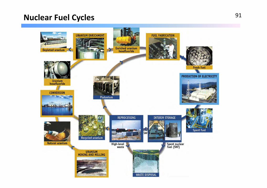
Nuclear Fuel Cycles 91

Level of each radiation penetration on typical material 92
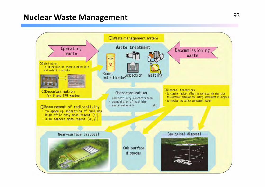
Nuclear Waste Management 93

Deep geological waste disposal 94

2.2 Nuclear power plant technology 95
• Current situation of nuclear energy
• Working process and merits of nuclear power plant
• Radioactive level and dosages
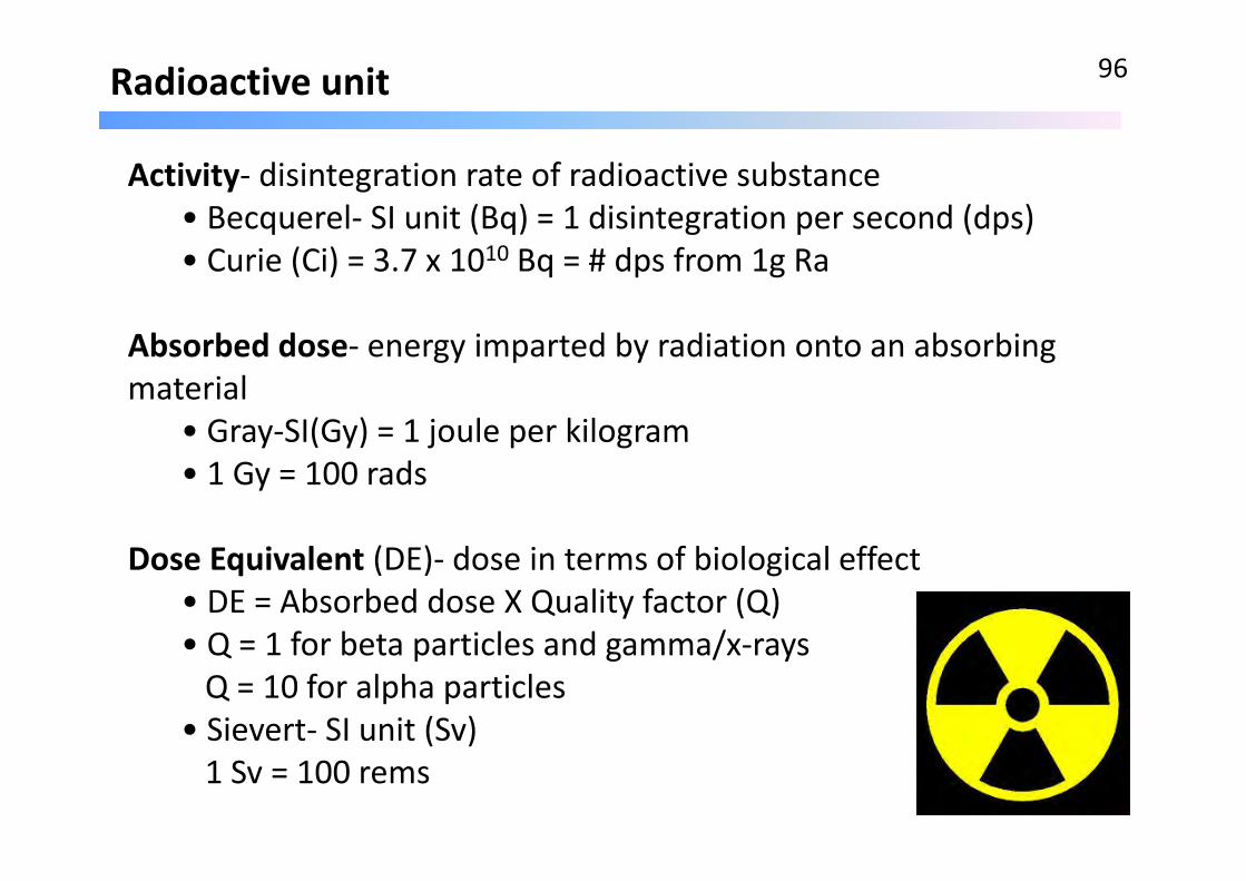
Radioactive unit 96
Activity‐ disintegration rate of radioactive substance• Becquerel‐ SI unit (Bq) = 1 disintegration per second (dps)• Curie (Ci) = 3.7 x 10¹⁰ Bq = # dps from 1g Ra
Absorbed dose‐ energy imparted by radiation onto an absorbing material
• Gray‐SI(Gy) = 1 joule per kilogram• 1 Gy = 100 rads
Dose Equivalent (DE)‐ dose in terms of biological effect• DE = Absorbed dose X Quality factor (Q)• Q = 1 for beta particles and gamma/x‐raysQ = 10 for alpha particles
• Sievert‐ SI unit (Sv)1 Sv = 100 rems
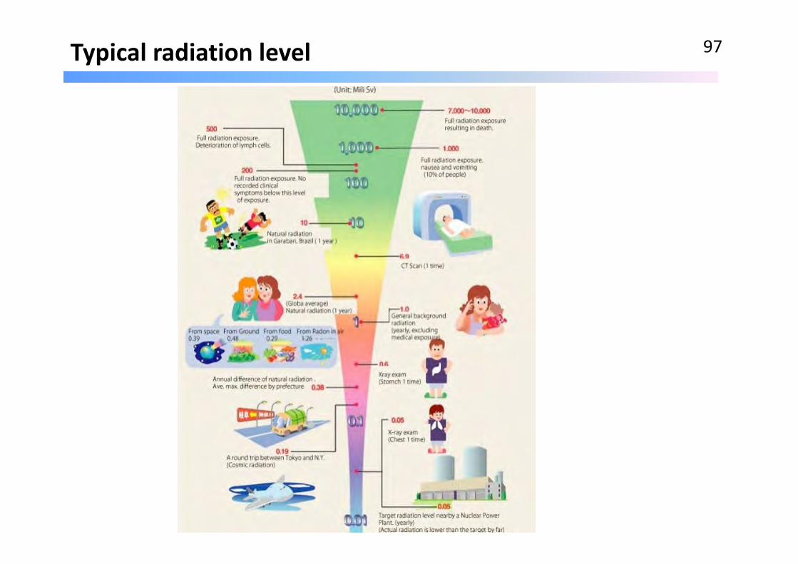
Typical radiation level 97

Thank You vey much for your kind attention
Q & A
98