theoretical analysis and experimental research on
TRANSCRIPT
Advanced Steel Construction Vol. 6, No. 4, pp. 949-962 (2010) 949
THEORETICAL ANALYSIS AND EXPERIMENTAL RESEARCH ON STABILITY BEHAVIOR OF STRUCTURAL STEEL TUBE
AND COUPLER FALSEWORK WITH X-BRACING
Hongbo Liu1, Zhihua Chen1,2*, Xiaodun Wang1 and Ting Zhou1
1 Department of Civil Engineering, Tianjin University, Tianjin, 300072, China 2 Tianjin Key Laboratory of Civil Engineering Structure & New Materials, Tianjin University,
Tianjin, 300072, China *(Corresponding author: E-mail: [email protected])
Received: 9 December 2009; Revised: 12 March 2010; Accepted: 18 March 2010
ABSTRACT: This paper presents a systematic study on stability of the structural steel tube and coupler falseworks with X-bracing (hereinafter referred to as STCF with X-bracing) through experimental and analytical investigations. Two full-scale STCF specimens were constructed and static tests were conducted in the lab in order to get the strength and failure modes of typical STCF with X-bracing. Test data from literature on two full-scale STCF specimens with same geometric parameters but without X-bracing are also adopted for comparison to investigate the effect of X-bracing on its structural property. Advanced nonlinear finite element analysis was conducted on the specimen models using ANSYS in order to study the capacity and failure modes of the tested specimens. Based on the FEA results, parametric studies were carried out in order to investigate the influence of various geometric parameters on the capacity of STCF with X-bracing. Based on the experimental and analytical results, it seemed that the typical failure mode of STCF with X-bracing was that only upper two storey posts and the U-head buckled evidently about the short axis, and other lower posts deformed little which can be negligible, and the findings reveal that the existence of X–bracing causes an evident increase to the load carrying capacities of STCF, especially of STCF without additional spans. It is clear that the strength of the STCF with X-bracing system would 1) increase linearly with the right-angle coupler rotational stiffness, thickness of steel tube to a certain extent; 2) decrease linearly with post spacing, initial imperfection, the storey height to a certain extent; 3) decrease nonlinearly with the U-head height, the sweeping staff height, which has little effect on the failure load of STCF with X-bracing at initial stage and large effect at later stage.
Keywords: Steel tube and coupler falsework, X-bracing, experimental research, numerical modeling method, parametric analyses
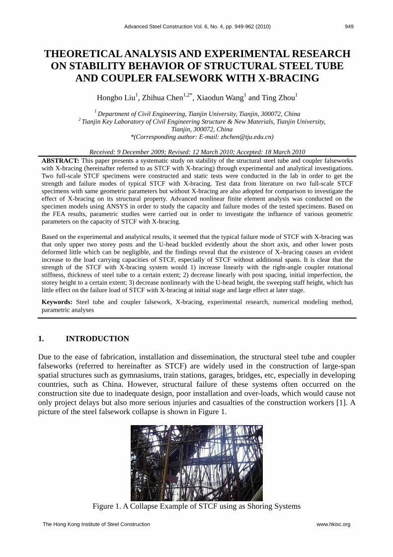
1. INTRODUCTION Due to the ease of fabrication, installation and dissemination, the structural steel tube and coupler falseworks (referred to hereinafter as STCF) are widely used in the construction of large-span spatial structures such as gymnasiums, train stations, garages, bridges, etc, especially in developing countries, such as China. However, structural failure of these systems often occurred on the construction site due to inadequate design, poor installation and over-loads, which would cause not only project delays but also more serious injuries and casualties of the construction workers [1]. A picture of the steel falsework collapse is shown in Figure 1.
Figure 1. A Collapse Example of STCF using as Shoring Systems
The Hong Kong Institute of Steel Construction www.hkisc.org

950 Theoretical Analysis and Experimental Research on Stability Behavior of Structural Steel Tube and Coupler Falsework with X-Bracing
Currently, most researches on falseworks have focused on the door-type steel falseworks [2~6], high clearance falsework systems [7~8], single-wall and two-wall steel tube and coupler falseworks [9~12], but very few has referred to the STCF. However, many disastrous collapses of STCF have happened during the construction because of no rational design rules for STCF available currently in the national standards in China, Japan, UK and USA [13~17]. As a result, there is a growing concern in many countries on the structural properties of this type of system. Semi-rigid behavior of couplers in STCF was investigated through experiments by R.G. Beale [9], Li Guoqiang [11], Jin Weiliang [12] and Chen Zhihua [18]. Moreover, the stability behavior of STCF without X-bracing was also studied through both numerical simulation and experimental research [18]. It should be noted that there is remarkable difference in the stability behavior between STCF with X-bracing and STCF without X-bracing, so the stability behavior of STCF with X-bracing must be studied. Due to the high slenderness of posts, existence of X-bracing, unloading area, and the semi-rigid properties of couplers, it is important for the researchers to understand the structural behaviors of STCF through both experimental and analytical studies. 2. OBJECTIVES AND SCOPE OF INVESTIGATION An extensive study has been conducted on the stability behavior of STCF with X-bracing through both experimental and analytical investigations. Here the STCF with X-bracing system consists of steel beams (horizontal members), steel posts (vertical members), X-bracing members, right-angle coupler at the intersection of beams and posts, swivel coupler at the intersection of posts and X-bracing member etc. The objectives of the study included:
Indentify the strength and failure modes of STCF with X-bracing through experiments. Present an effective numerical modeling method considering the semi-rigid nature of the
couplers to analyze the structural properties of STCF with X-bracing and verify it by full-scale tests.
Investigate the effect of various geometric parameters on the stability of STCF with X-bracing.
The following tasks have been undertaken to achieve the research objectives:
Task 1 – Two full-scale tests were carried out to provide not only insights into the structural behavior of STCF with X-bracing, but also data to compare with and verify the numerical results obtained from subsequent finite element analyses. Test result of two full-scale tests from literature is also adopted for comparison.
Task 2 – Establish FEM model based on the characteristics of STCF with X-bracing
system and verify it by results of full-scale tests. Task 3 – A series of parametric analysis were carried out to investigate the effect of various
geometric characters on system stability.
Hongbo Liu, Zhihua Chen, Xiaodun Wang and Ting Zhou 951
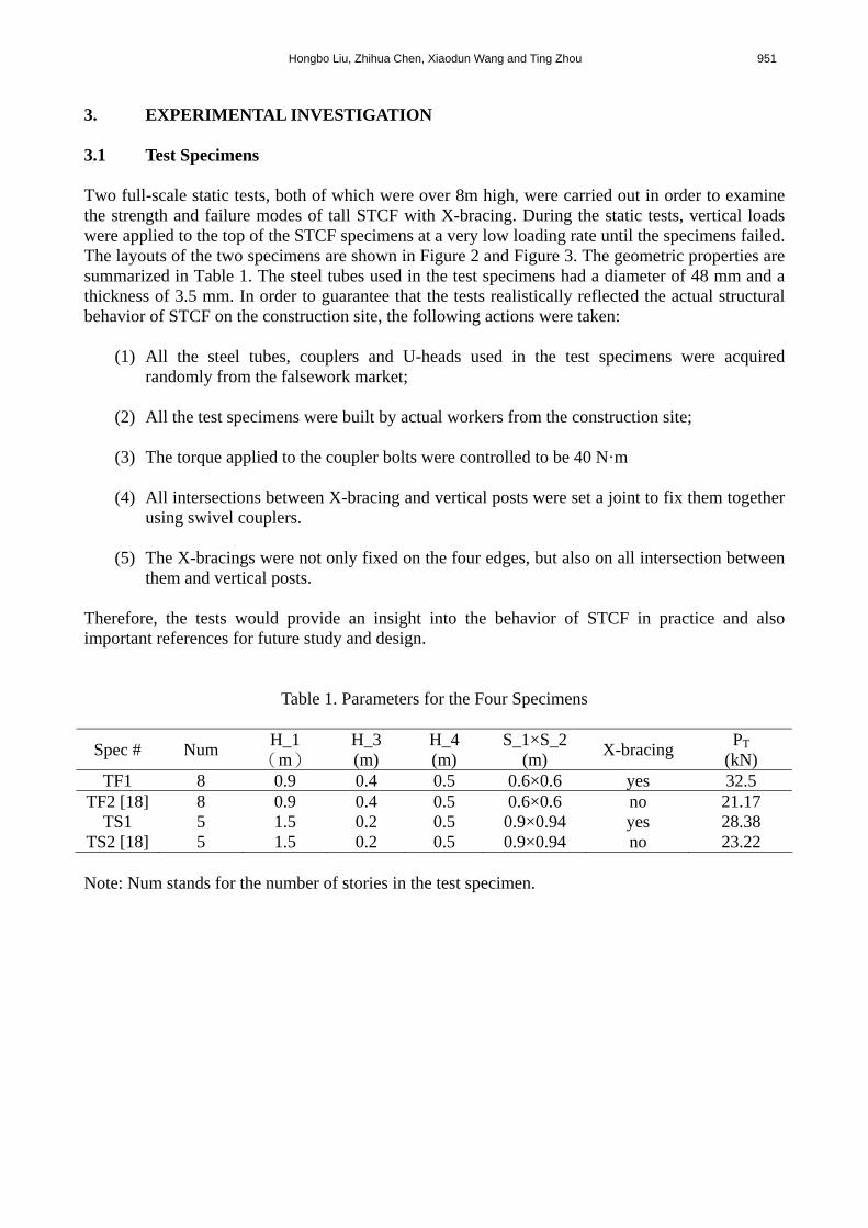
3. EXPERIMENTAL INVESTIGATION 3.1 Test Specimens Two full-scale static tests, both of which were over 8m high, were carried out in order to examine the strength and failure modes of tall STCF with X-bracing. During the static tests, vertical loads were applied to the top of the STCF specimens at a very low loading rate until the specimens failed. The layouts of the two specimens are shown in Figure 2 and Figure 3. The geometric properties are summarized in Table 1. The steel tubes used in the test specimens had a diameter of 48 mm and a thickness of 3.5 mm. In order to guarantee that the tests realistically reflected the actual structural behavior of STCF on the construction site, the following actions were taken:
(1) All the steel tubes, couplers and U-heads used in the test specimens were acquired randomly from the falsework market;
(2) All the test specimens were built by actual workers from the construction site; (3) The torque applied to the coupler bolts were controlled to be 40 N·m (4) All intersections between X-bracing and vertical posts were set a joint to fix them together
using swivel couplers. (5) The X-bracings were not only fixed on the four edges, but also on all intersection between
them and vertical posts.
Therefore, the tests would provide an insight into the behavior of STCF in practice and also important references for future study and design.
Table 1. Parameters for the Four Specimens
Spec # Num H_1
( )m H_3 (m)
H_4 (m)
S_1×S_2 (m)
X-bracing PT
(kN) TF1 8 0.9 0.4 0.5 0.6×0.6 yes 32.5
TF2 [18] 8 0.9 0.4 0.5 0.6×0.6 no 21.17
TS1 5 1.5 0.2 0.5 0.9×0.94 yes 28.38 TS2 [18] 5 1.5 0.2 0.5 0.9×0.94 no 23.22
Note: Num stands for the number of stories in the test specimen.

952 Theoretical Analysis and Experimental Research on Stability Behavior of Structural Steel Tube and Coupler Falsework with X-Bracing
(a) Elevation View from South (b) Elevation View from West
(c) Plan View
Figure 2. General Arrangement of TF1
Hongbo Liu, Zhihua Chen, Xiaodun Wang and Ting Zhou 953
(a) Elevation View from South (b) Elevation View from West
(c) Plan View
Figure 3. General Arrangement of TS1
3.2 Loading Mechanism and Test Set-Up Four loading frames with a height of 10 m were fabricated for the tests. Two 50-ton hydraulic jacks were fastened to the top of each loading frame, and vertical loads were firstly applied by the hydraulic jacks to the two top steel distribution beams, and then transferred to the group of bottom steel distribution beams in the perpendicular direction, and finally to the falsework system, as is shown in Figure 4. In this way, the vertical concentrated loads applied by the hydraulic jacks would be converted into a vertical uniform load applied to the top of the falsework system through two steel tubes with same diameter with post of specimen right below the bottom distribution beams and the U-heads, as is shown in Figure 4(b). Because there are four loading frames, there are eight 50-ton hydraulic jacks used in each test, and they were fixed under loading frames simultaneously and not gradually. Moreover, all hydraulic jacks were connected with each other by oil tube in order to make them bring pressure simultaneous.

954 Theoretical Analysis and Experimental Research on Stability Behavior of Structural Steel Tube and Coupler Falsework with X-Bracing
(a) Elevation View from West (b) Elevation View from South
(c) (d)
Figure 4. Loading Mechanism and Test Set-Up
For these falseworks, it is clear from Figure 5 that the bottom end of the falsework system was not restrained in the horizontal directions, so theoretically it is free. However, during the tests as well as in common practices, there were no horizontal displacements observed at this location, therefore the boundary condition here would be considered pinned. On the top end of the falsework system, the boundary condition there would be considered as a roller condition, since the horizontal friction force between the two steel tubes and the bottom surface of the distribution steel beams was very small, as is shown in Figure 4(b).
Figure 5. Bottom of the Falsework System
Considering the safety of the experiments, the collapse of the falsework system was not allowed. Since the pressure induced by the hydraulic jacks will decrease once the STCF specimen reached its peak load and start unloading due to instability, the specimen would be considered “failed” at this point and the test will be stopped.
Hongbo Liu, Zhihua Chen, Xiaodun Wang and Ting Zhou 955
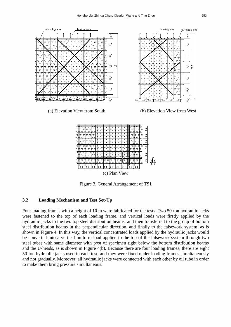
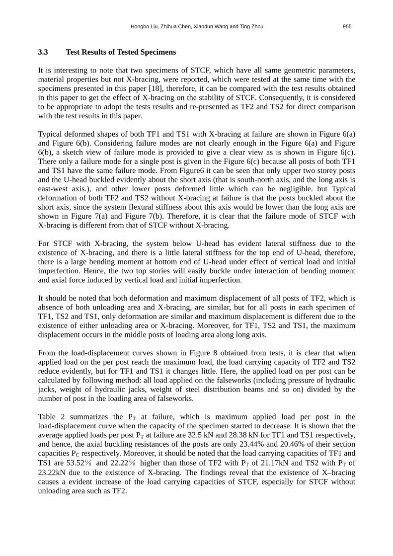
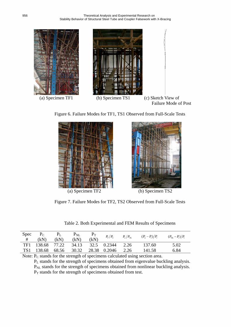
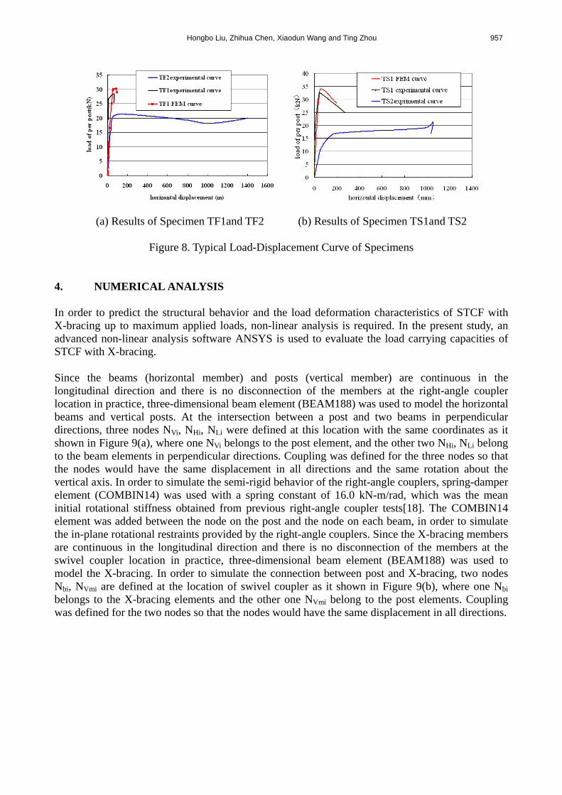
3.3 Test Results of Tested Specimens It is interesting to note that two specimens of STCF, which have all same geometric parameters, material properties but not X-bracing, were reported, which were tested at the same time with the specimens presented in this paper [18], therefore, it can be compared with the test results obtained in this paper to get the effect of X-bracing on the stability of STCF. Consequently, it is considered to be appropriate to adopt the tests results and re-presented as TF2 and TS2 for direct comparison with the test results in this paper. Typical deformed shapes of both TF1 and TS1 with X-bracing at failure are shown in Figure 6(a) and Figure 6(b). Considering failure modes are not clearly enough in the Figure 6(a) and Figure 6(b), a sketch view of failure mode is provided to give a clear view as is shown in Figure 6(c). There only a failure mode for a single post is given in the Figure 6(c) because all posts of both TF1 and TS1 have the same failure mode. From Figure6 it can be seen that only upper two storey posts and the U-head buckled evidently about the short axis (that is south-north axis, and the long axis is east-west axis.), and other lower posts deformed little which can be negligible. but Typical deformation of both TF2 and TS2 without X-bracing at failure is that the posts buckled about the short axis, since the system flexural stiffness about this axis would be lower than the long axis are shown in Figure 7(a) and Figure 7(b). Therefore, it is clear that the failure mode of STCF with X-bracing is different from that of STCF without X-bracing. For STCF with X-bracing, the system below U-head has evident lateral stiffness due to the existence of X-bracing, and there is a little lateral stiffness for the top end of U-head, therefore, there is a large bending moment at bottom end of U-head under effect of vertical load and initial imperfection. Hence, the two top stories will easily buckle under interaction of bending moment and axial force induced by vertical load and initial imperfection. It should be noted that both deformation and maximum displacement of all posts of TF2, which is absence of both unloading area and X-bracing, are similar, but for all posts in each specimen of TF1, TS2 and TS1, only deformation are similar and maximum displacement is different due to the existence of either unloading area or X-bracing. Moreover, for TF1, TS2 and TS1, the maximum displacement occurs in the middle posts of loading area along long axis. From the load-displacement curves shown in Figure 8 obtained from tests, it is clear that when applied load on the per post reach the maximum load, the load carrying capacity of TF2 and TS2 reduce evidently, but for TF1 and TS1 it changes little. Here, the applied load on per post can be calculated by following method: all load applied on the falseworks (including pressure of hydraulic jacks, weight of hydraulic jacks, weight of steel distribution beams and so on) divided by the number of post in the loading area of falseworks. Table 2 summarizes the PT at failure, which is maximum applied load per post in the load-displacement curve when the capacity of the specimen started to decrease. It is shown that the average applied loads per post PT at failure are 32.5 kN and 28.38 kN for TF1 and TS1 respectively, and hence, the axial buckling resistances of the posts are only 23.44% and 20.46% of their section capacities PC respectively. Moreover, it should be noted that the load carrying capacities of TF1 and TS1 are 53.52% and 22.22% higher than those of TF2 with PT of 21.17kN and TS2 with PT of 23.22kN due to the existence of X-bracing. The findings reveal that the existence of X–bracing causes a evident increase of the load carrying capacities of STCF, especially for STCF without unloading area such as TF2.
956 Theoretical Analysis and Experimental Research on Stability Behavior of Structural Steel Tube and Coupler Falsework with X-Bracing
(a) Specimen TF1 (b) Specimen TS1 (c) Sketch View of
Failure Mode of Post
Figure 6. Failure Modes for TF1, TS1 Observed from Full-Scale Tests
(a) Specimen TF2 (b) Specimen TS2
Figure 7. Failure Modes for TF2, TS2 Observed from Full-Scale Tests
Table 2. Both Experimental and FEM Results of Specimens
Spec #
PC
(kN) PL
(kN)
PNL
(kN)
PT
(kN) T CP P
L NLP P ( )L t tP P P ( )NL t tP P P
TF1 138.68 77.22 34.13 32.5 0.2344 2.26 137.60 5.02 TS1 138.68 68.56 30.32 28.38 0.2046 2.26 141.58 6.84 Note: PC stands for the strength of specimens calculated using section area. PL stands for the strength of specimens obtained from eigenvalue buckling analysis.
PNL stands for the strength of specimens obtained from nonlinear buckling analysis. PT stands for the strength of specimens obtained from test.
Hongbo Liu, Zhihua Chen, Xiaodun Wang and Ting Zhou 957
(a) Results of Specimen TF1and TF2 (b) Results of Specimen TS1and TS2
Figure 8. Typical Load-Displacement Curve of Specimens
4. NUMERICAL ANALYSIS In order to predict the structural behavior and the load deformation characteristics of STCF with X-bracing up to maximum applied loads, non-linear analysis is required. In the present study, an advanced non-linear analysis software ANSYS is used to evaluate the load carrying capacities of STCF with X-bracing. Since the beams (horizontal member) and posts (vertical member) are continuous in the longitudinal direction and there is no disconnection of the members at the right-angle coupler location in practice, three-dimensional beam element (BEAM188) was used to model the horizontal beams and vertical posts. At the intersection between a post and two beams in perpendicular directions, three nodes NVi, NHi, NLi were defined at this location with the same coordinates as it shown in Figure 9(a), where one NVi belongs to the post element, and the other two NHi, NLi belong to the beam elements in perpendicular directions. Coupling was defined for the three nodes so that the nodes would have the same displacement in all directions and the same rotation about the vertical axis. In order to simulate the semi-rigid behavior of the right-angle couplers, spring-damper element (COMBIN14) was used with a spring constant of 16.0 kN-m/rad, which was the mean initial rotational stiffness obtained from previous right-angle coupler tests[18]. The COMBIN14 element was added between the node on the post and the node on each beam, in order to simulate the in-plane rotational restraints provided by the right-angle couplers. Since the X-bracing members are continuous in the longitudinal direction and there is no disconnection of the members at the swivel coupler location in practice, three-dimensional beam element (BEAM188) was used to model the X-bracing. In order to simulate the connection between post and X-bracing, two nodes Nbi, NVmi are defined at the location of swivel coupler as it shown in Figure 9(b), where one Nbi belongs to the X-bracing elements and the other one NVmi belong to the post elements. Coupling was defined for the two nodes so that the nodes would have the same displacement in all directions.
958 Theoretical Analysis and Experimental Research on Stability Behavior of Structural Steel Tube and Coupler Falsework with X-Bracing
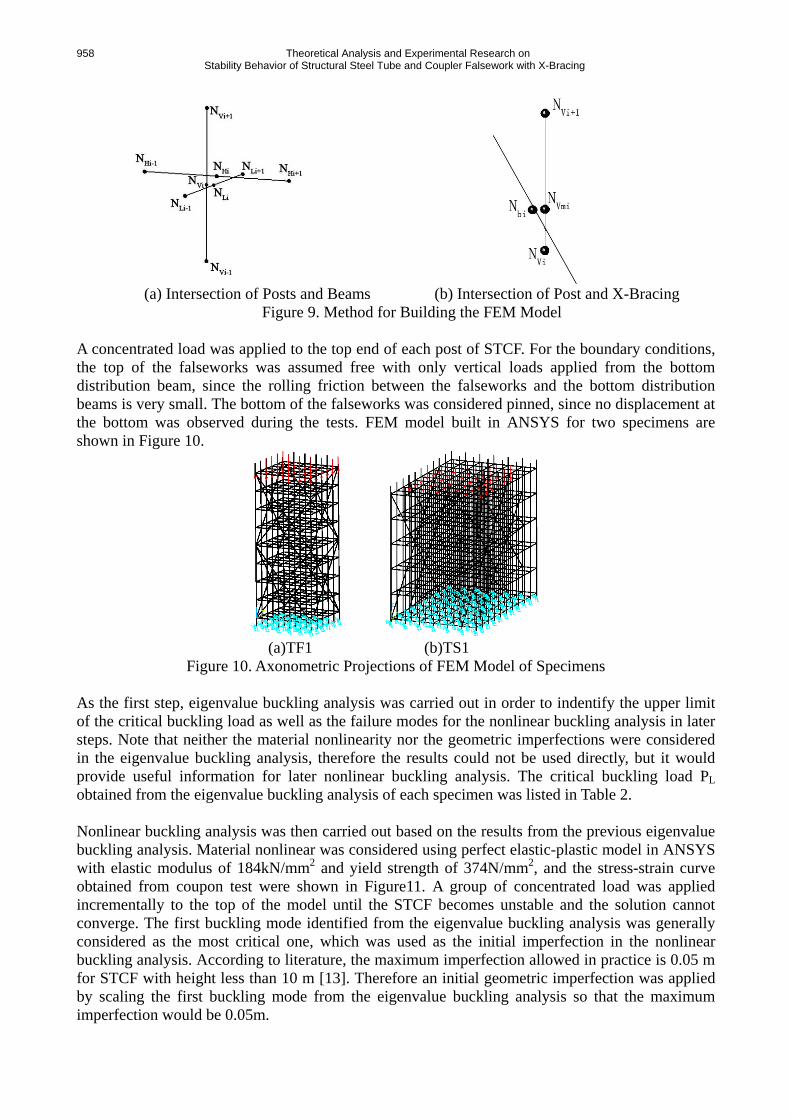
(a) Intersection of Posts and Beams (b) Intersection of Post and X-Bracing
Figure 9. Method for Building the FEM Model A concentrated load was applied to the top end of each post of STCF. For the boundary conditions, the top of the falseworks was assumed free with only vertical loads applied from the bottom distribution beam, since the rolling friction between the falseworks and the bottom distribution beams is very small. The bottom of the falseworks was considered pinned, since no displacement at the bottom was observed during the tests. FEM model built in ANSYS for two specimens are shown in Figure 10.
(a)TF1 (b)TS1
Figure 10. Axonometric Projections of FEM Model of Specimens As the first step, eigenvalue buckling analysis was carried out in order to indentify the upper limit of the critical buckling load as well as the failure modes for the nonlinear buckling analysis in later steps. Note that neither the material nonlinearity nor the geometric imperfections were considered in the eigenvalue buckling analysis, therefore the results could not be used directly, but it would provide useful information for later nonlinear buckling analysis. The critical buckling load PL obtained from the eigenvalue buckling analysis of each specimen was listed in Table 2. Nonlinear buckling analysis was then carried out based on the results from the previous eigenvalue buckling analysis. Material nonlinear was considered using perfect elastic-plastic model in ANSYS with elastic modulus of 184kN/mm2 and yield strength of 374N/mm2, and the stress-strain curve obtained from coupon test were shown in Figure11. A group of concentrated load was applied incrementally to the top of the model until the STCF becomes unstable and the solution cannot converge. The first buckling mode identified from the eigenvalue buckling analysis was generally considered as the most critical one, which was used as the initial imperfection in the nonlinear buckling analysis. According to literature, the maximum imperfection allowed in practice is 0.05 m for STCF with height less than 10 m [13]. Therefore an initial geometric imperfection was applied by scaling the first buckling mode from the eigenvalue buckling analysis so that the maximum imperfection would be 0.05m.
Hongbo Liu, Zhihua Chen, Xiaodun Wang and Ting Zhou 959
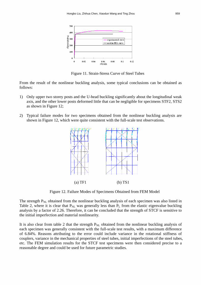
Figure 11. Strain-Stress Curve of Steel Tubes
From the result of the nonlinear buckling analysis, some typical conclusions can be obtained as follows: 1) Only upper two storey posts and the U-head buckling significantly about the longitudinal weak
axis, and the other lower posts deformed little that can be negligible for specimens STF2, STS2 as shown in Figure 12;
2) Typical failure modes for two specimens obtained from the nonlinear buckling analysis are
shown in Figure 12, which were quite consistent with the full-scale test observations.
(a) TF1 (b) TS1
Figure 12. Failure Modes of Specimens Obtained from FEM Model
The strength PNL obtained from the nonlinear buckling analysis of each specimen was also listed in Table 2, where it is clear that PNL was generally less than PL from the elastic eigenvalue buckling analysis by a factor of 2.26. Therefore, it can be concluded that the strength of STCF is sensitive to the initial imperfection and material nonlinearity. It is also clear from table 2 that the strength PNL obtained from the nonlinear buckling analysis of each specimen was generally consistent with the full-scale test results, with a maximum difference of 6.84%. Reasons attributing to the error could include variance in the rotational stiffness of couplers, variance in the mechanical properties of steel tubes, initial imperfections of the steel tubes, etc. The FEM simulation results for the STCF test specimens were then considered precise to a reasonable degree and could be used for future parametric studies.

960 Theoretical Analysis and Experimental Research on Stability Behavior of Structural Steel Tube and Coupler Falsework with X-Bracing
5. PARAMETRIC STUDIES Parametric studies were conducted in order to indentify the controlling factors for the critical buckling load of the STCF with X-bracing system. The parameters investigated included the rotational stiffness of the right-angle couplers, the storey height, the sweeping staff height (that is the height of H_3 illustrated in Figure 2 and Figure 3), the post spacing, the U-head height, thickness of steel tubes and initial imperfection. The primary layout of the FE model here is as same as specimen TF1. Results from the parameter studies are shown in Figure 13. From the Figure 13, it is clear that the critical buckling load of the STCF with X-bracing system would 1) increase linearly with the right-angle coupler rotational stiffness, thickness of steel tube to a certain extent as it shown in Figure 13(a)~(b); 2) decrease linearly with post spacing, initial imperfection, the storey height to a certain extent as it shown in Figure 13(c)~(e); 3) decrease nonlinearly with the U-head height, the sweeping staff height as it shown in Figure 13(f)~(g), which has little effect on the failure load of STCF with X-bracing at initial stage and large effect at later stage.
(a) Influence of Rotational Stiffness of Right-Angle Coupler (b) Influence of Thickness of Steel Tube
(c) Influence of Post Space (d) Influence of Initial Imperfection
(e) Influence of Storey Height (f) Influence of U-Head Height

Hongbo Liu, Zhihua Chen, Xiaodun Wang and Ting Zhou 961
(g) Influence of Sweeping Staff Height
Figure 13. Results of Parameter Studies on STCF with X-Bracing by FEM
6. CONCLUSIONS This paper presents an extensive study on the stability behavior of STCF with X-bracing through full-scale tests as well as numerical investigations. It is demonstrated that: 1) The failure mode of STCF with X-bracing is different from that of STCF without X-bracing.
Typical deformed shapes for STCF without X-bracing at failure is that the posts buckled about the short axis, since the system flexural stiffness about this axis would be lower than the long axis. But typical deformed shapes for STCF with X-bracing at failure is that only upper two storey posts and the U-head buckled significantly about the short axis, and other lower posts deformed little which can be negligible;
2) Both deformed shapes and maximum displacement of all posts of TF2, which is absence of both unloading area and X-bracing, are similar, but for all posts in each specimen of TF1, TS2 and TS1, only deformed shapes are similar and maximum displacement is different due to the existence of either unloading area or X-bracing. Moreover, for TF1, TS2 and TS1, the maximum displacement occurs in the middle posts of loading area along long axis;
3) Axial buckling resistances of the column members are only 23.44% and 20.46% of their section capacities respectively, so the stability is the control factor for failure;
4) The load carrying capacities of TF1 and TS1 are 53.52% and 22.22% higher than those of TF2 and TS2 due to the existence of X-bracing. The findings reveal that the existence of X–bracing causes a significant increase to the load carrying capacities of STCF, especially of STCF without unloading area such as TF2;
5) The FEM simulation results for the STCF test specimens were then considered precise to a reasonable degree and could be used for future parametric studies;
6) It is clear that the critical buckling load of the STCF with X-bracing system would 1) increase linearly with the right-angle coupler rotational stiffness, thickness of steel tube to a certain extent; 2) decrease linearly with post spacing, initial imperfection, the storey height to a certain extent; 3) decrease nonlinearly with the U-head height, the sweeping staff height, which has little effect on the failure load of STCF with X-bracing at initial stage and large effect at later stage.
ACKNOWLEDGEMENTS
The authors sincerely thank the Tianjin Municipal Science and Technology Commission for the financial support provided to this research project (Research Project No.08JCZDJC19600). The authors also thank the China Academy of Building Research for their partial support on the experiment research and are especially grateful to Mr. Qun Liu, chief engineer, for his advices and support during the process.
962 Theoretical Analysis and Experimental Research on Stability Behavior of Structural Steel Tube and Coupler Falsework with X-Bracing
REFERENCES [1] Milojkovic, B., Beale, R.G. and Godley, M.H.R., “Determination of the Factors of Safety of
Standard Scaffold Structures”, Proceedings of International Conference on Advances in Steel Structures, 2002, Vol. 1, pp. 303-10.
[2] Chan, S.L., Zhou, Z.H., Chen, W.F., Peng, J.L. and Pan, A.D., “Stability Analysis of Semi-Rigid Steel Scaffolding”, Eng. Struct., 1995, Vol. 17, pp. 568–74.
[3] Peng, J.L., Pan, A.D.E. and Chan, S.L., “Simplified Models for Analysis and Design of Modular Falsework”, J. Construct. Steel Res. 1998, Vol. 48, pp. 189-209.
[4] Peng, J.L., Pan, A.D.E. and Chen, W.F., “Approximate Analysis Method for Modular Tubular Falsework”, ASCE, J. Struct. Engng., 2001, Vol. 127, pp. 256–63.
[5] Weesner, L.B. and Jones, H.L., “Experimental and Analytical Capacity of Frame Scaffolding”, Eng. Struct., 2001. Vol. 23, pp. 592-99.
[6] Yu, W.K., Chung, K.F. and Chan, S.L., “Structural Instability of Multi-Storey Door-Type Modular Steel Scaffolds”, Eng. Struct., 2004, Vol. 26, pp. 867-61.
[7] Peng, J.L., Pan, A.D., Rosowsky, D.V., Chen, W.F., Yen, T. and Chan, S.L., “High Clearance Scaffold Systems during Construction-1: Structural Modeling and Modes of Failure”, Eng. Struct., 1996, Vol. 18, pp. 247-57.
[8] Peng, J.L., Pan, A.D., Rosowsky, D.V., Chen, W.F., Yen, T. and Chan, S.L., “High Clearance Scaffold Systems During Construction-2: Structural Analysis and Development of Design Guidelines”, Eng. Struct., 1996, Vol. 18, pp. 258-67.
[9] Beale, R.G. and Godley, M.H.R., “Numerical Modeling of Tube and Fitting Access Scaffold Systems”, Advanced Steel Construction, 2006, Vol. 2, pp. 199-223.
[10] Xu, C.B., Zhang, T.Z. and Pan, J.L., et al., “Theoretical and Experimental Studies on the Structural Behavior of Two-Wall Steel Tube and Coupler Scaffold”, Journal of Harbin Architectural and Civil Engineering Institution, 1989, Vol. 2, pp. 38-55. (In Chinese)
[11] Ao, H.F. and Li, G.Q., “Investigation of Overall Load-Bearing Stability Capacity of Tube-and-Coupler Scaffolds”, Chinese Quarterly of Mechanics, 2004, Vol. 25, pp. 213-218. (In Chinese)
[12] Yuan, X.X., Jin, W.L., Lu, Z., Liu, X. and Chen, T.M., “A Study on the Stability Bearing Capacity of Fastener-Style Tubular Steel Formwork-Supports”, J. China Civil Engineering Journal, 2006, Vol. 39, No. 5, pp. 43-50. (In Chinese)
[13] Chinese Standards Institution, GJG 130-2001: Technical Code for Safety of Steel Tubular Scaffold with Couplers in construction: 2001. (In Chinese)
[14] British Standards Institution, BS EN 12811: Temporary Works Equipment: 2003. [15] British Standards Institution, BS EN 12812: Falsework—Performance Requirements and
General Design: 2004. [16] American National Standards Institution. ANSI/ASSE A10.8-2001: Safety Requirements
for Scaffolding: 2001. [17] Japanese Industrial Standards Committee. JIS A 8951-1995: Tubular Steel Scaffolds: 1995. [18] Liu, H.B, Zhao, Q.H, Wang, X.D., et al., “Experimental and Analytical Studies on Stability
of Structural Steel Tube and Coupler Scaffold without X-Bracing”, Eng. Struct., 1996, Vol. 32, pp. 1003-1015.
[19] Chen, Z.H., Liu, H.B. and Zhou, T., et al., “Parametric Analysis of Spatial Steel Structures Using APDL Language”, Beijing: China WaterPower Press, 2009. (In Chinese)