theoretical modeling of an a6 relativistic magnetron
TRANSCRIPT

University of Central Florida University of Central Florida
STARS STARS
Faculty Bibliography 2000s Faculty Bibliography
1-1-2004
Theoretical modeling of an A6 relativistic magnetron Theoretical modeling of an A6 relativistic magnetron
D. J. Kaup University of Central Florida
Find similar works at: https://stars.library.ucf.edu/facultybib2000
University of Central Florida Libraries http://library.ucf.edu
This Article is brought to you for free and open access by the Faculty Bibliography at STARS. It has been accepted for
inclusion in Faculty Bibliography 2000s by an authorized administrator of STARS. For more information, please
contact [email protected].
Recommended Citation Recommended Citation Kaup, D. J., "Theoretical modeling of an A6 relativistic magnetron" (2004). Faculty Bibliography 2000s. 4478. https://stars.library.ucf.edu/facultybib2000/4478

Theoretical modeling of an A6 relativistic magnetronD. J. Kaupa)
University of Central Florida, Orlando, Florida
~Received 27 August 2003; accepted 9 February 2004; published online 11 May 2004!
The analytical modeling of the initialization stage of a relativistic magnetron of the A6 cylindricaldesign is presented, where only two dominant modes are used: a direct current~dc! backgroundmode and a radio frequency~rf! pump mode. These two modes interaction nonlinearly, with the dcbackground being driven by the dc electromagnetic forces and the ponderomotive forces of the rfmode, while the rf mode is the most unstable linear eigenmode on this dc background. In cylindricalgeometry, the diocotron resonance is found to occur over a broader region than in planar models. Infact, in certain parameter regimes, the resonance can appear twice, once near the Brillouin edge, andsecond, just below the anode. In these parameter regimes, the oscillating electrons can beaccelerated twice. Numerical results for the initiation stage agree quite well with the knownexperimental results on the A6. Results for 350 kV are emphasized, and similar results have alsobeen obtained for voltages between 300 and 500 kV. Numerical data are presented that indicate apossible source for a nonlinear instability, which could give rise to pulse shortening, in the lateroperating stage, where the device should be smoothly delivering power. ©2004 AmericanInstitute of Physics.@DOI: 10.1063/1.1710518#
I. INTRODUCTION
The analytical modeling of crossed-field vacuum de-vices, such as crossed-field amplifiers~CFAs! and magne-trons, can give new insights into their operation, and thephysical processes that occur inside them. These deviceshave been analyzed with ‘‘particle-in-cell’’~PIC! codes~seeRefs. 1–4! and guiding center theory~see Refs. 5–8, andreferences therein!. Our modeling approach is complemen-tary, in that we use Fourier modes. The original Fourier mul-tiscale expansion for a planar magnetron model was first de-scribed in Ref. 9, and the importance of the second-order~quasilinear! conditions for determining the operating elec-tron density profiles was detailed in Refs. 10 and 11. Thisapproach produces reasonable predictions for the phaseshifts, dc current flow, and other characteristics of thesedevices.12 Furthermore, when the total density is recon-structed from the high-frequency rf wave and the dc back-ground, the resulting density profiles are similar to thoseseen in numerical simulations, showing the well-knownspoke structure~see Fig. 2 below!.
Any strong rf electric field propagating in the slow wavestructure of a crossed-field, electron vacuum device willdrive a Brillouin sheath13 unstable10,11 by means of a Ray-leigh instability,14 whenever a wave-particle resonance~dio-cotron! occurs inside the sheath. This linear wave-particleinstability originates in a Rayleigh-like equation11 with ashear flow. Once this linear instability initializes, the laminarflow of the electrons is strongly disturbed, and a nonlinearinstability is then triggered, which is a second-order diffu-sion process.9,15,16 This nonlinear diffusion process causesthe electrons to redistribute into a new average background
dc density profile, one which will be in equilibrium with thenonlinear diffusion process, which is driven by the pondero-motive pressure of the propagating rf wave.10,11 This diffu-sion process is driven by the density gradient at the edge ofthe sheath,10 which for a Brillouin flow is very large. Thetotal profile, consisting of the new stationary dc backgroundand the rf oscillations, appears as an oscillating backgroundwith a series of periodic ‘‘spokes,’’ as seen in numericalsimulations with PIC codes.1,2,6 These spokes carry the dccurrent from the cathode to the anode. The physics of theturn-on process for developing these spokes has been de-scribed in Ref. 12.
Previous studies of the A6 have included the study ofrelativistic planar models6,17–19and also the observation thatthere is an instability which could arise whenever the dcradial current becomes too large.20 Studies by others haveincluded the derivation of the dispersion relation and thegrowth rates of the diocotron instability for a relativistic pla-nar magnetron in the guiding center approximation for atenuous beam.21 Also, the importance of the rf inducedE3B drift velocity in reducing the efficiency of such a devicehas been treated by Riyopoulos22 in the guiding center ap-proximation.
Here we use analytical modeling to present an analyticaland a numerical treatment of the relativistic cylindrical mag-netron in the A6 configuration. In carrying out this study, ourprimary purpose will be to devise an analytical model,whereby one can expose and understand the physical pro-cesses occurring inside the magnetron. Thus we concentratefirst on the analytics, selecting from the equations, in a con-sistent fashion, those terms which would be dominant. Themajor assumption that we use is that the dominant terms arethose that come from the dc background and a single rfmode.9,23Secondary assumptions are also used, where appro-priate, to complement this one. Once the analytical results
a!Telephone: 407-823-2795: fax: 407-823-6253. Electronic mail:[email protected]
PHYSICS OF PLASMAS VOLUME 11, NUMBER 6 JUNE 2004
31511070-664X/2004/11(6)/3151/14/$22.00 © 2004 American Institute of Physics

are obtained, then we concentrate on numerics. In this man-ner, one is able to reveal features about these devices thatcannot be easily accessed by other methods. We have beenable to outline the operating range of the parameters and givethe various characteristics at any operating point, such as thephase shifts, current flow, growth rates, and power flow.12,23
We can also study the various physical processes which oc-cur inside the tube, noting features that may be useful in thedesign of these devices.23,24
In Sec. II, we discuss the relativistic equations for an A6configuration. Then in Sec. III, we discuss the equations de-termining the dc background solution, provided the densityprofile is known. In Sec. IV, we do the same for the rf solu-tion. It is in Sec. V where we will describe how one canobtain the density profile, by use of the second-order nonlin-ear diffusion equation. Here we impose the adiabatic ap-proximation and use it to determine how the density profilereshapes.
To clarify what we mean by the adiabatic approximation,we briefly describe it here. First, the dc density profile isdetermined by a nonlinear~quasilinear! diffusion equation,first detailed by Davidson.15 This equation consists of thesum of three basic terms. Lettingn0 be the dc density profile,D the nonlinear diffusion coefficient~which is proportionalto the rf power!, t a slow time, andS a source term~nonlin-ear in n0), then this equation is of the basic form]tn0
1] r(D] rn0)1S50. As is well known, diffusion equationswill generally evolve so that the contributions from the firstterm, ]tn0 , tend to vanish. In this case, we have the majorbalance occurring between the nonlinear diffusion term andthe source term. The adiabatic approximation is where weassume that this balance is the key balance, so that we thenignore the first term. As to why this balance occurs, we notethat as the device is initiated, due to the relatively slow~tothe electrons! changes in the dc voltage, one would expectthe electrons to have time to diffuse and reshape the densityprofile. Thus one would expect the transient states to besmall, and therefore the density profile, at every instant oftime, should be essentially an equilibrium state, as deter-mined by the stationary solutions of this nonlinear diffusionequation. This form of modeling is shown to produce reason-able predictions for the behavior of these devices.
Once we obtain the analytical results, then we turn tonumerics to evaluate the solutions of these equations. Onefeature of these equations is that they are ‘‘stiff’’ near theBrillouin edge, requiring care in varying the parameters andthe initial values. At the same time, one has to determine fourinternal parameters, whose values are essential in obtainingthe correct dc and rf solutions, as well as to match to theapplied voltage and external ambient magnetic field. Howthis can be done by an iteration procedure is described inSec. VI. Our general results will be presented mostly ingraphical form in Sec. VII, and concluding remarks will bepresented in Sec. VIII.
II. BASIC EQUATIONS AND APPROACH
The geometry and configuration that we shall be using isshown in Fig. 1, which is a representation of the A6.25 In the
middle is the cathode, located atr 5r 1 . We take the externalambient dc magnetic field to be of strengthBext, and alignedalong the negativez axis ~into the paper!, which gives theelectron drift velocity to be in the negativef direction. Nextto the cathode will be an electron sheath~not shown! whichwill extend out toward the anode, located atr 5r 2(.r 1).The anode is composed of a slow wave structure~SWS!consisting of vanes and slots, which is simply a collection ofwave guides, inside of which the rf wave will resonate andgrow.
To model the A6, it is necessary to perform a fully rela-tivistic treatment of the system in cylindrical geometry. Westart with the relativistic cold fluid equations for a singlespecies, which are
] tn1“•~ny!50, ~1!
] t~gy!1~y"“ !~gy!1E1y3B50, ~2!
and Maxwell’s equations,
“3E1] tB50, ~3!
“3B21
c2] tE52
1
c2ny, ~4!
with the initial conditions
“•B50, ~5!
“•E52n. ~6!
In the above, we have takenn to be the electron plasmafrequency squared (4pe2r/m) wheree(m) is the magnitudeof the electronic charge~mass! andr is the electron numberdensity.E is e/m times the electric field, andB is e/(mc)times the magnetic field. Thus the units ofE are acceleration,and the unit ofB is frequency. We will take the fluid velocityvector to be always in therf plane, and all quantities~ex-cept one! to be independent of thez coordinate. The oneexception is the second-order dc contribution to thef com-ponent of the second-order dc magnetic field, which, as weshall see, must be taken to be linear inz. This follows from
FIG. 1. A representation of the geometry of a cylindrical magnetron. Thecathode is the surface of the inner shaded area atr 5r 1 and the anode is atr 5r 2 , which is the inner surface of the vanes in the vane-slot slow-wavestructure surrounding the cathode. The sheath will be formed just outside thecathode surface. Thez direction is out of the paper.
3152 Phys. Plasmas, Vol. 11, No. 6, June 2004 D. J. Kaup

Ampere’s law and the presence of the second-orderr com-ponent of the dc current density.g is the standard relativisticfactor, 1/A12y•y/c2.
It is from these equations~1!–~6!, the geometry, an ex-pansion in dominant modes, the specified parameters, andsimplifying assumptions that all our results will follow. Aswe have done before,23 we assume that we will only need toconsider one oscillating rf mode and the dc backgroundmode, on which the rf mode propagates. This will be a basicmodel, which one could further refine as the need arises. Tosimplify matters, we will assume that we will not need to useFloquet theory, although the system is periodic in the azi-muthal direction~see discussion on this point below!. Thuswe take the dc solution to be cylindrically symmetric and therf mode to be a single mode of the formei (mf2vt), wheremis the azimuthal modal number andv is a complex fre-quency, with the real part being the rf oscillation frequencyand the imaginary part~Im v5s! being the growth rates. Atthe same time, we will allow for a slow-time dependence inthe zeroth-order dc terms, since these quantities will have toslowly shift in order to accommodate, and adjust to, anygrowing rf mode. This expansion is primarily an expansionin terms of Fourier components, one component~dc! whichis independent off and the fast time, and one component ofthe formei (mf2vt). We will later expand the dc componentin a simple multiple-time scale with only two scales: a con-stant part and a slow-time part.9 Thus the general form of thisexpansion, for any quantityG, is
G5G0~r ,t!1eG1~r !ei ~mf2vt !1e2G2~r !e2st, ~7!
wheret is the slow time and the expansion parameter ise. Inline with the adiabatic approximation, we will assume thatthe derivation of any zeroth order quantityG0 , with respectto t, will always be small compared to the ponderomotiveand gradient terms.
Here we will only consider the initialization of the de-vice. One starts with an external magnetic field appliedacross the device, and then the dc voltage is turned on,slowly compared to the electron cyclotron frequency. Theelectron sheath forms with an approximate cylindricallysymmetric, stationary Brillouin flow. As the dc voltage in-creases, the Brillouin shear flow eventually becomes strongenough to excite the linear wave particle~diocotron! reso-nance (Rv/m5ydrift /r ), whereRv is the real part of thecomplex frequencyv. At this point, a growing linear insta-bility initializes. As it grows, due to nonlinear terms in theequations, it will beat against itself and createponderomotive-like forces, which become additional contri-butions to the dc components of the equations. These forcescause shifts in the dc quantities, proportional to the square ofthe rf amplitudes, as well as determine the shape of the elec-tron density profile.
In regard to Floquet theory, we make the following com-ment. For the A6, Floquet theory would require that wecouple all modes where them’s differed by66 j , wherej isany integer. However, as long as one is not near an edge of a
Brillouin zone~the 2p mode is at such an edge, thep modeis midway between edges!, any Floquet solution would gen-erally be dominated by one of these modes. We thereforeassume that the Floquet solution is indeed dominated by oneof these modes, and that modes differing by66 j from thatmode may be ignored. For the A6 and our geometry, them523 mode is thep mode, for which this approximationwould work best. We also expect it to be a good approxima-tion for the two adjacent modes,m522 andm524, butpossibly poor for them521 andm525 modes.
III. BACKGROUND SOLUTION
We begin our analysis by inserting an expansion of theform ~7!, for all dependent variables, into the relativisticcold-fluid, Maxwell equations, and expand the equations. Wenote thatB2f must be linear inz, in order to satisfy Ampe`re’slaw. As mentioned earlier, the zeroth-order terms will all begenerally dependent on the slow-time scale,t5e2t.
The equations will decompose into coefficients of vari-ous powers ofeimf ande. We solve iteratively, starting at thelowest power ofe~50!. The e50 terms of each equation~1!–~6!, gives us the conditions for the existence of the‘‘background’’ or dc solution.16 Detailing these, from New-ton’s equations, we obtain a quadratic relation for the driftvelocity,
E02g0
y02
r1y0B050, ~8!
where it is understood that the zeroth-order quantities givenabove have the appropriate component for that field. (E0 isthe radial component,y0 is thef component, andB0 is thezcomponent!. From Poisson’s law, given the density, the dcelectric field is given by
1
r] r~rE0!52n0 , ~9!
and from Ampe`re’s law,
] rB052n0y0 /c2, ~10!
we can determine the radial dependence ofB0 . We take thedc electric field to vanish at the cathode~the space-chargelimited current condition! and the average of the dc magneticfield over the interaction region to be equal to the externallyapplied dc magnetic fieldBext. The latter also conserves themagnetic flux through the interaction region. These condi-tions are
E0~r 1!50, Er 1
r 2rB0dr5~r 2
22r 12!Bext. ~11!
A third condition is that the electric field must give the ap-plied dc voltage,
3153Phys. Plasmas, Vol. 11, No. 6, June 2004 Theoretical modeling of an A6 relativistic magnetron

2Er 1
r 2E0dr5Vdc. ~12!
We shall later need the derivative ofy0 with respect tor.This can be obtained by differentiating~8! and using~9! and~10! to eliminate the derivatives ofB0 andE0 . That resultsin
] ry05rn0g0
22y0B0
rD B0, ~13!
where the quantityDB0 is
DB05B02g0y0
r~11g0
2!. ~14!
We solve this system by taking~13! to define y0 , withy050 at the cathode~this is equivalent to the space-chargelimited current condition!, and the integral of~10! to defineB0 . Its value at the cathode will be adjusted so that theintegral in ~11! is satisfied. Then we use~8! to evaluateE0 . If the denominator in~13! ever becomes zero at somevalue of r in the interaction region, then this corresponds toan unallowable state, sincey0 must remain finite. This con-dition never occurs in a planar system~where r 5`). In acylindrical system, in order to have magnetic insulation, onemust use a stronger magnetic field than in the planar case,because in addition, one must also overcome the centrifugalforce on the electrons. The conditionDB0.0 insures thatany additional magnetic field, required to counteract the cen-trifugal force and to maintain magnetic insulation, will bepresent.
IV. THE rf SOLUTION
Now we turn our attention to the first-order~rf! solu-tions. These are the linearized equations, and have beengiven before.9,17,18,26–28An important point in the consider-ation of the form that we shall use is that it is the particledynamics that are the most important and fundamental. Con-sequently, we have found that it is best to eliminate the elec-tromagnetic fields in favor of the velocities,9,27 or equiva-lently, in terms of Lagrangian displacements.14,18,29For thissystem, the first-order Lagrangian displacements can be de-fined by
y1r52 ivej r , y1f52 ivejf1S y0
r2] ry0D j r , ~15!
where ve5v2my0 /r , which is the Doppler shifted fre-quency seen in the moving electron’s frame,j is the first-order Lagrangian displacement, and the subscript 1 will gen-erally refer to a first-order quantity.
Of the rf components of the electromagnetic fields, twocomponents of the rf magnetic field are found to vanish(B1r505B1f). We also take thez components of the elec-tric field, the velocity, and the Lagrangian displacement to
vanish (E1z505y1z5jz), so that the rf motion will remainin the r -f plane. The rf component of the number density isgiven by
n1521
r] r~rn0j r !2 i
n0jf
r, ~16!
and the nonzero electromagnetic field components are givenby
E1f5g03jfve
22 iD B0j rve , ~17!
B1z52v
c2me
@rg0ve222DB0y02g0~11g0
2!y02
1n0y0me#j r2ir vDB0ve
c2me
jf , ~18!
where
me5m2vr y0
c2, ~19!
ve5v2my0
r. ~20!
Due to the combination of the relativistic factor and thecylindrical symmetry, the analytical expressions for the equa-tions of motion becomes essentially too complex for handcalculations. Both the planar relativistic case17,19 and the cy-lindrical nonrelativistic case30 have been obtained by hand.However, the combination of relativistic plus cylindrical in-creases the complexity by an exponential factor. Conse-quently, from this order on, we have resorted to using thesymbolic computational softwareMACSYMA ~Ref. 31! to ob-tain the expansion of, and the reduction of, these equations.By taking either the nonrelativistic limit, or the planar limit,one can verify that these equations do have the proper lim-iting forms, and therefore can verify these equations in thoselimits. We have done this for the planar limit, and do findagreement with the previous planar equations.23 We shallpresent no derivation here, and shall simply present the finalreduced results.
The first-order equations, with the aid ofMACSYMA, canbe reduced to a set of second-order ordinary differentialequations~ODE!, of the form
dj r
dr5Crr j r1 iCrfjf , ~21!
djf
dr5 iCfrj r1Cffjf . ~22!
With the aid ofMACSYMA, the coefficients are found to be
3154 Phys. Plasmas, Vol. 11, No. 6, June 2004 D. J. Kaup

Crr 521
r2
2g02y0S ve1me
y0
r Dmec
21
g06y0
Ar2 F4meve1y0
c2r~r 2ve
222g02y0
2!G2g0
3y0
Amec2 H n0S 2ve1
y0me
r D12g0
3ve
r 2@2r 2ve
2
1~g0223!y0
2#J 1g0
3ve
c2DB0mer@r 2ve
21y02~3g0
221!#12g0
4
ADB0r H g03~g0
211!
r 3 Fmever 2g02
y03
c2 Gy022n0meveJ
1g0
4
c2ADB0merH ve
3g03@r 2ve
21y02~g0
223!#22g0
5~11g02!y0
6ve
c2r 21n0F r 2ve
32y02ve~11g0
2!12g02
y03
rmeG J , ~23!
Crf52g02 me
r1
g02rve
2
c2me
12g06~11g0
2!y0ve
Ar21
g03ve
2
c2AmeF rn01
g03
r S r 2ve212g0
2y0
4
c2 D G1g0
5y02ve
c2DB0r2
2g05y0ve
2
c2DB0me
1g0
4ve
ADB0r 3 H y02F2~11g0
2!1r 2ve
2
c2 Gg052n0r 2~3g0
221!J 22g0
9ve2y0
c2ADB0mer2
@r 2ve22y0
2~11g02!#, ~24!
Cfr5me
g02r
S 122rg03 n0
A D22g0
2y02
Ar3 F ~3g0221!me1g0
2 r y0
c2veG1
2y03
c2Ar2veF2n01g0
6y0
4
c2r 2G14y0m
g02merve
1r 4ve
413y02r 2ve
2~3g0221!12y0
2~g0426g0
211!
Ac2g02mer
31
n0g0
c2Amer@r 2ve
21~3g0221!y0
2#1y0g0
c2DB0r 2 S 4me1r y0
c2ve
2D2
1
DB0rv rF2n0S 22
1
g02D 2
y0~g0414g0
221!
r 2c2g0G2
2y0
c2DB0meH n01
g0
r 2@2r 2ve
21y02~r 0
223!#J1
g05y0
ADB0r 4 H 4me@r 2ve22~11g0
2!y02#2
n0y0ver3
g0c21
y0rve
c2@r 2ve
22~113g02!y0
2#J2
2g05y0
c2ADB0mer4
@r 2ve22~11g0
2!y02#F2r 2ve
21~g0223!y0
21n0r 2
g0G1
g04~11g0
2!y04
c2ADB0r 3veFg0
3y02
r 21n0G , ~25!
Cff521
r2
2g02y0
c2r2
4g02mey0
r 2ve
12g0
2y0ve
c2me
1g0
6y02
Ar3 F2~11g02!2
r 2ve2
c2 G1g0~3g0
221!n0
Ar1
2vey0g06
c2Amer2
3F2r 2ve22y0
2~32g02!1
n0r 2
g03 G2
g0~11g02!2y0
DB0r 21
2me
DB0rveFn02g0
3~11g02!
y02
r 2G2rg0
3
c2DB0meF n0
g03 S ve1me
y0
r D1veS ve
212g0
2y04
c2r 2 D G22g0
7~11g02!y0
ADB0r 4@r 2ve
22~11g02!y0
2#2g0
7ve
c2ADB0merH n0
g03 @r 2ve
22~11g02!y0
2#
1ve2@r 2ve
22~32g02!y0
2#22g02~11g0
2!y0
6
c2r 2J , ~26!
where
A5S DB01g03 y0
r D 2
1g04
y02
r 22g0
4ve2. ~27!
We will need two boundary conditions for this second-orderset of ODE’s. The first one will come fromE1f vanishing atthe cathode~conducting surface condition!, and the secondone will come from matching the interior plasma solution tothe electromagnetic field solution in the SWS. For the latter
we require that, at the anode, the ratio ofE1f /B1z in theplasma region to match the same as that in the SWS, whichwill be assumed to be a vacuum region. To calculate the ratioon the plasma side, we need the forms ofE1f andB1z , givenabove by~17! and ~18!. To calculate the ratio on the SWSside, we solve Maxwell’s equations for the given vane-slotconfiguration, subject to standard boundary conditions on theslot surfaces. In the numerical calculations of this ratio, wehave included the first three azimuthal modes in each slot.
Given these boundary conditions and the background
3155Phys. Plasmas, Vol. 11, No. 6, June 2004 Theoretical modeling of an A6 relativistic magnetron

density profile, for each value ofm, one then determines the~complex! eigenvalues ofv which will satisfy the boundaryconditions. In general, there can be several eigenvalues ofvfor each value ofm. While all of these would in general beinitially excited and would proceed to grow at their indi-vidual growth rates, it is the one with the largest growth ratethat will eventually dominate. We then search through the listof eigenvalues for that one, and that is the one that we take asthe operating mode. Typically, for the parameter space thatwe have searched, we have found that this mode will havemin the range of24<m<21.
V. NONLINEAR DIFFUSION–SECOND-ORDER dc
In second order, the rf wave beats against itself, creatinga ponderomotive force. This force causes a nonlinear diffu-sion to initiate, wherein the steep density gradient of theBrillouin flow is reduced. Due to the nonlinear terms in~1!–~6!, this diffusion causes the dc solution to slowly shift awayfrom its initial solution, at a rate proportional to the square ofthe rf amplitude. An analysis of all such shifts in the nonrel-ativistic case was given in Refs. 9 and 15, along with adiscussion of the evolution of the background density profile.
Although the zeroth-order solution does evolve duringthe nonlinear diffusion process, by using the adiabatic ap-proximation discussed in the Introduction, we bypass thetransient region and go directly to the stationary solution,wherein the electrons have redistributed themselves to be inbalance with the ponderomotive and electromagnetic forces.We have shown that this nonlinear diffusion process will begenerally quite rapid.10
In the fully relativistic case, there is a lag in the growthof the second-order fields~due to the finite speed of light!which is not present in the nonrelativistic case. Along withthis, the strong dc radial current creates aB2f component,linear in z, which then will generate smallz components ofthe velocity and electric field, proportional toz. Dependingon the width of the device inz, this could become an impor-tant consideration. However, if the device is sufficiently thin,then these effects will be small and can be ignored. The onlyconsequence of assuming a thin device and ignoring thesezcomponents ofy andE will be that thef component of~3!will not be exactly satisfied. Also, in an actual device, the useof ‘‘end caps’’ tends to limit these longitudinal effects andmotions.
Taking the above thin approximation, we have that thesecond-order dc solution will have the following features.The second-order corrections to the dc magnetic field aregiven by
B2r50, B2f5B0c
2 C2zr2
c2r, B2z52
1
2sr] r~rE2f!,
~28!
whereB0c is the value of the zeroth-order dc magnetic fieldat the cathode,C2 is essentially the radial dc velocity of theelectrons, andr 2 is the radius of the device at the inside ofthe vanes~anode!. ~The factors ofB0c , r 2 , and c in theexpression forB2f are there simply to normalizeC2 to avelocity.! Since the device will carry a dc radial current, one
must have a nonzeroB2f component, and thusC2 must benonzero. This constant will reappear later as a key quantityin the nonlinear diffusion equation, where it will essentiallydetermine the width of the Brillouin-like section of the pro-file.
The second-order electric field has only af component(E2r505E2z), which satisfies the equation
] r2E2f1Ce1] rE2f1Ce0E2f5CeS, ~29!
where the coefficients are
Ce151
r1
n0y0
c2DB0S 12
4g03s2
D D ,
Ce0521
r 21
n0y0
c2DB0rS 12
4g03s2
D D 24s2
c2 S 11n0
D D ,
~30!
CeS522sQAf14n0QNfs2
c2D
12n0QNrs
c2DB0S 12
4g03s2
D D ,
and where the denominator termD is defined as
D51
g0S DB01g0
3 y0
r D 2
1g03S 4s21
y02
r 2D 2n0 . ~31!
The boundary conditions onE2f are that it must vanish atboth the cathode and the anode, since it is independent off,and both surfaces will appear to be conducting surfaces.32
Also, QA is the rf part of Ampe`re’s equation,QN is the rf partof Newton’s equation. These parts are given by
QAr5n1* y1r
c21c.c.,
QAf5n1* y1f
c21c.c.,
~32!
QNr5H B1z* y1f1 img0
ry1ry1f* 12g0
3y0y1f* y1r
s
c21c.c.J
1g0] r uy1r u223g03
y02
rc2uy1r u2
1y0g0
c2DB0
uy1r u2F2n022g03
y02
r 2~11g0
2!23g02 y0
r G1
g03
ruy1fu2~123g0
2!,
3156 Phys. Plasmas, Vol. 11, No. 6, June 2004 D. J. Kaup
QNf5H 2B1z* y1r1g03y1r* ] ry1f2g0
3F ~3g0224!
1
r
23n0y0
DB0c213g0
3~g0211!
y02
r 2c2DB0Gy1r* y1f
1c.c.J 12g03 y0s
c2~ uy1r u213g0
2uy1fu2!
22sg0uy1r u2
DB0uveu2] rn0 ,
and where the ‘‘* ’’ indicates the complex conjugate of thequantity, and ‘‘1c.c.’’ means to add the complex conjugateof all the preceeding terms that are contained inside thatparticular bracket. Continuing, from the second-order New-tonian equations, we have that the second-order changes inthe velocities are given by
y2r522g0
2s
D~y0B2z1QNr!1
DB0
g0D~E2f1QNf!,
y2f521
DB0S 12
4g03s2
D D ~y0B2z1QNr!
22s
D~E2f1QNf!, ~33!
y2z50.
The next and last result which follows from the second-order dc equations is the nonlinear diffusion equation, whichdetermines the stationary density profile. This equation, inthe adiabatic approximation, where we ignore]tn0 and theslow-time derivatives of all other quantities, is
Dnl] rn01Nnln01C2B0c2 D
r 2
r50, ~34!
where
Dnl52suj r u2
g0F S DB01g0
3 y0
r D 2
1g04S y0
2
r 214s2D G ,
~35!
Nnl52g02sQNr2Dc2QAr02
DB0QNf0
g02g0
2y0] rE2f
2S DB0
g01g0
2 y0
r DE2f .
In ~35!, the subscript ‘‘0’’s on theQ’s indicate that all termsproportional to] rn0 have been removed.@In ~34!, all that wedid was to move any and all terms which contained the radialderivative ofn0 , over into the nonlinear diffusion coefficientDnl , which is where they are now found. OnlyQAr andQNf
did contain such terms.# To solve Eq.~34!, we must appendone boundary condition, which we take to ben0a , which isthe value of the stationary density at the anode,r 5r 2 . Thisvalue of n0a will appear as a control parameter in our nu-merical solutions.
VI. NUMERICAL METHOD OF SOLUTION
At this point, we now have a closed system of ordinarilydifferential equations, and we have sufficient boundary con-ditions to define a solution, if one exists. The zeroth-order dcequations are nonlinear. Givenn0(r ), one can integrate themfrom the cathode up to the anode, given the value ofB0c , thevalue ofB0 at the cathode. This value is initially unknown,but one can start with an initial guess, and by using theNewton–Raphson method, rapidly converge to the correctvalue that will satisfy the second condition in~11!. In regardto the first-order rf equations, they are linear in the rf vari-ables, but nonlinear in the zeroth-order quantities. Given avalue for the complex frequencyv, the mode numberm, andthe dc solution, by requiringE1f , ~17!, to vanish at thecathode, then matching at the SWS, we can uniquely deter-mine the rf solution, up to an overall normalization constant.The second-order dc equations are linear in the second-ordervariables, but nonlinear in the zeroth-order variables, andquadratic~nonlinear! in the rf fields. The key quantity todetermine will be the stationary density profilen0 , whosedetermining equation is~34!. Of course, inspection revealsthat once one has the stationary density profile, then all theother quantities may be determined by either quadrature ordifferentiating and/or algebra, whence the stationary densityprofile is the key quantity to obtain. We have found that theseprofiles may be obtained by a simple iteration technique. Thebasin of convergence is generally quite large, unless one isnear a point where the solution no longer exists.
The general iteration method that we used is as follows.One starts with some reasonable density profilen0(r ), eithera combination of a box plus a ramp, or some nearby profile,and then solve for the dc electromagnetic fields. Once onehas a starting profile and the accompanying dc fields, thenone proceeds to solve the rf equations~22! for the radial andazimuthal displacements, using the given boundary condi-tions below Eq.~27!. One checks all mode numbers,26,m,0, for the most unstable mode, varying the complexvalue of v until the electron plasma solution at the anodematches that of the SWS. With this, one then has the eigen-valuev, the mode numberm, and the rf solution, up to theoverall arbitrary normalization constant.
To find the normalization constant for the rf solution, werequire the total density variations, dc plus the rf oscillations,as in ~7!, to never be negative, since a negative electrondensity would be unphysical. This condition then gives anupper limit to the value of the normalization coefficient,which also is the precise value that must be used, for thefollowing reason. In the absence of the rf waves, the densityprofile would relax back to the Brillouin value, which hasn0a vanishingly small. For the rf wave to exist, thenn0a mustbe lifted off of its Brillouin value of zero, and become suf-ficiently large to accommodate the amplitude of the rf oscil-lations, without driving the total electron density negative.Turning this argument around then for a givenn0a , onewould take the amplitude of the rf density oscillations,un1(r )u, to be just large enough to exactly fit under the den-sity profile n0(r ). Examples of this will be seen in Fig. 2 inthe next section.
3157Phys. Plasmas, Vol. 11, No. 6, June 2004 Theoretical modeling of an A6 relativistic magnetron

Once the rf normalization constant has been determined,then the rf fields are uniquely determined, up to an overallphase. Although this rf solution is consistent with the dcfields, the dc fields may not be consistent with these new rffields. So now we turn to satisfying the condition on thedensity profile, given by~34!, as well as calculating thesecond-order fieldsE2f andB2z . The condition~34! is whatis known as a ‘‘stiff’’ ODE. Its solution will typically haveexponential behavior with very short scale lengths, on theorder of the width of the edge of the classical Brillouinsheath. Furthermore, due to the stiffness of this ODE, as onevaries the unknown parameterC2 , the solution can rather
suddenly violate the single-particle stability limit.~In thenonrelativistic limit, the single-particle stability range for theelectron density isn0,B0
2, which is just the Brillouin limit.!To complicate the problem further, the boundary conditionsare mixed, with the value ofn0 being specified at the anoden0a and other parameters being specified at the cathode.
There are probably several iteration schemes whichwould solve these equations. The iteration that we have usedis to integrate~34! to obtainn0 , and then varyC2 , usingNewton–Raphson, until the new density profile gives thecorrect applied dc voltageVdc. Outside of this iteration, wehave another iteration whereby we varyB0c until we have
FIG. 2. Plots of certain density profiles for the A6 at 350 kV and an ambient magnetic field ofBext518 GHz ~6.4 K G! case, when the rf field is in them522 mode. In the first plot, forn0a50.11, we see the density profile and the magnitude of the rf oscillations for an initiating rf field, with a peak in the rfdensity oscillations at the diocotron resonance. In the second plot, we have combined the dc and the rf solutions to compose the total density profile, at aslightly lower value ofn0a50.10. In the third plot, we show the configuration when the rf wave reaches its maximum amplitude, atn0a50.125. In the finalplot, we see how the configuration changes when one tries to exceed this limit. Here we have the solution forn0a50.14, showing how the rf amplitude at theanode will decrease.
FIG. 3. In the first panel we show a plot of the magnitudes of the Lagrangian displacements, for the same parameters as Fig. 2~c!. In ~b!, we show a plot ofthe real part ofve vs r for the same solution.
3158 Phys. Plasmas, Vol. 11, No. 6, June 2004 D. J. Kaup
both the correctVdc and Bext. Then we use~11!, ~12!, and~8! to determine the new values ofE0 , B0 , and y0 byquadrature.
Once we have the new density profile and the new dcfields, then we have the dc solution consistent with the rffields. However, now the old rf fields will generally be in-consistent with the new dc fields. So we return to the calcu-lation of the rf fields and then back to the second-order dcfields and the density profile. We continue these iterationsuntil all the coefficients,Vdc, B0c , m, v, andC2 , have sta-bilized to within a specified relative variation of no morethan typically 1026. However sometimes the convergencedoes not occur, and that is usually because no solution canexist for the chosen values of the parameters (Vdc, Bext, andn0a). This can show up as an rf solution having a vanishinggrowth rate for allm values, due toVdc being too small forthe given value ofBext, or even as no solution existing forn0
due ton0a being too large, and sometimes even being toosmall. Occasionally we have found that the solution will con-verge to some period-2 solution, wherein the values ofB0c ,m, v, andC2 converge to a repetition of alternating values.24
Period-3 and period-4 solutions have also been seen. Thus itis not surprising that sometimes one also sees chaotic resultsoccurring. These equations are nonlinear and little is knownabout necessary conditions for solutions to exist.
VII. NUMERICAL RESULTS
As the first example of our results, we show in Fig. 2 aset of four typical results for the density profilen0 and themagnitude on the rf density oscillations atV5350 kV, Bext
518 GHz~6.4 K G!, and for the mode numberm522. Thisis toward the low side of the operational range of the mag-netic field, and in this region, the density profiles tend to be‘‘soft,’’ and the mode numbers correspondingly tend to below, and on the order of21–23. The horizonal axis is theradius in cm, where the cathode is on the left, starting at 1.58cm, and the anode is on the right, at 2.11 cm. Figure 2~a!shows the solution whenn0a50.11, and we see that the rffield is becoming well developed, with a peak in theun1ucurve, which is where the diocotron resonance occurs at theedge of the sheath.@In all these figures, the units ofn isfrequency squared, in units of~rad/nsec!2. However, we willgive n0a as a ratio compared to the square of the electroncyclotron frequency, in rad/nsec, of the external magneticfield. As such,n0a is essentially just the ratio of the dc den-sity at the anode, compared to the dc density at the cathode.#As one can also see, the rf field has been scaled so that it fitsentirely under then0 curve, and just touches it at the anodeon the right. Consequently, the total density is everywherenonnegative. In Fig. 2~b!, we show a two-dimensional view
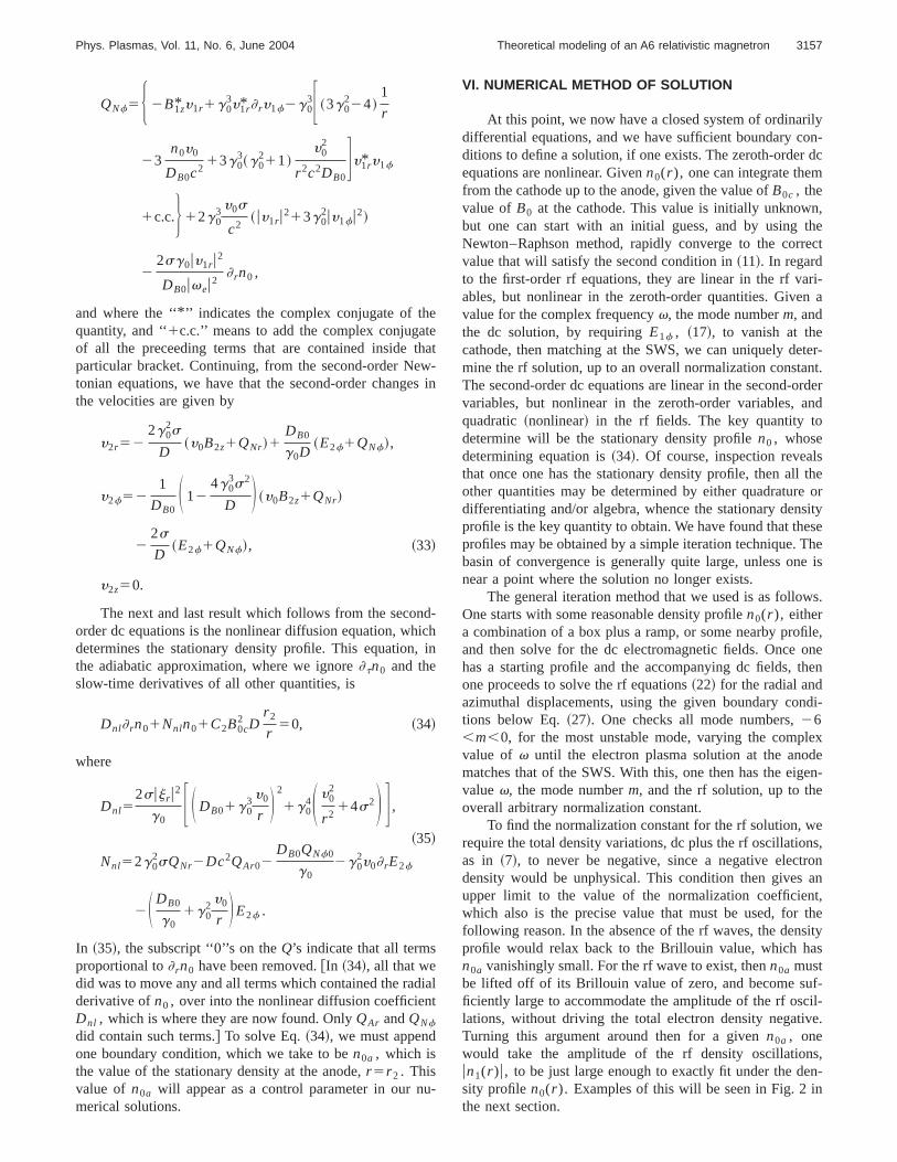
FIG. 4. Similar to Fig. 3, except forBext521 GHz~7.5 K G! andn0a50.044. This figure shows a second diocotron resonance just under the anode, and thecorresponding increase in the oscillations of the azimuthal displacements.
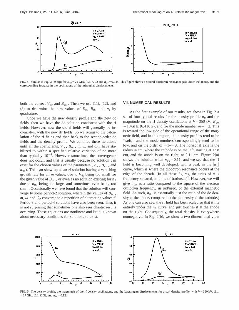
FIG. 5. The density profile, the magnitude of the rf density oscillations, and the Lagrangian displacements for a soft density profile, withV5350 kV, Bext
517 GHz ~6.1 K G!, andn0a50.12.
3159Phys. Plasmas, Vol. 11, No. 6, June 2004 Theoretical modeling of an A6 relativistic magnetron

for a single period of the rf wave at a slightly smaller valueof the amplitude of the rf wave,n0a50.10. ~In these three-dimensional plots, each coordinate has been scaled from zeroto unity.! Here the cathode is at the back on the left, whereone clearly sees the sheath. Coming out of the sheath is aspoke of electrons, reaching up to the anode, in the fore-ground at the right.
As the amplitude of the rf wave at the anode increases,the first thing that happens is that the value ofn0a will bepushed to larger values. The second thing that happens is thatthe diocotron peak will grow and generally narrow. Eventu-ally, it will touch the n0 curve, as shown in Fig. 2~c! forn0a50.125. This now is effectively the largest operating am-plitude that the rf wave can have at these parameters, be-cause now, the rf amplitude becomes limited by the dio-cotron peak, and not the rf amplitude at the anode. Anexample of this is clearly shown in Fig. 2~d!, which is for theslightly higher value ofn0a50.14. Note that now, at theanode, a gap has opened up between the background densityand the rf density oscillations, with the net result that the rfoscillation amplitude hasdecreasedat the anode. Solutionssuch as this latter, with the gap, are probably unphysical orunstable, since they correspond to a reduced rf amplitude ofthe rf wave in the vanes. These observations are in line withprevious similar observations in Ref. 23.
In Fig. 3~a!, we show the rf Lagrangian displacementsfor then0a50.14 solution. The units for each axis is in cm s.One notes the enhanced amplitude of the rf oscillations in thef direction, at the diocotron resonance, as well as the begin-ning of another enhancement as one nears the anode. Thelatter can be understood from Fig. 3~b!, where we show thereal part ofve vs r. What is different here from the planarcase is that after going through the diocotron resonance~where the real part ofve50), this quantity then goesslightly negative, and then begins to turn back toward theresonance. In the planar case, or a low aspect ratio cylindri-cal case, such never happens, since the drift velocity is al-ways monotonically increasing in magnitude. However, in ahigh aspect ratio cylindrical case, such as the A6, one canhave the magnitude of the drift velocity decreasing after onepasses through the region of the sheath.~Mainly because theradial electric field will vary asr 21, once one is outside thesheath.! In almost all our solutions, we have seen the real
part of ve returning toward the resonance, after the sheathhas been passed, and in several cases, even crosses zero andhas a second resonance, just below the anode. An example ofthis is shown in Fig. 4. As one can see, there is a second peakin the rf oscillations at the second resonance, and of course,there will be a corresponding secondary boost to the ampli-tudes of the rf oscillations of the electrons, before they strikethe anode.
For other solutions at other ambient magnetic fields, wehave seen similar behaviors in the dc density profiles and therf Lagrangian displacements. Invariably, the lower magneticfields give a ‘‘soft’’ sheath, which in some cases, can extendout to one-half of the cathode-anode spacing. Furthermore,the magnitude of the Lagrangian displacements becomesmaller, even at the diocotron resonance, with the value atthe anode being even smaller still, only a small fraction ofthe maximum value at the diocotron resonance. A typicalexample is shown in Fig. 5. The slackness of the densityprofile and the lack of significant rf oscillations at the anodewould suggest that at these parameters, one should not ex-pect this to be an optimum operating state, and experimen-tally, it is not.25
At the higher magnetic fields, the sheath becomes quite‘‘hard,’’ and almost Brillouin in shape, except for a rathersmall ‘‘shelf’’ extending out to the anode, as shown in Fig. 6.The harder the density profile becomes, the smaller the at-tached shelf is, in order to have a consistent solution. It isthis relationship that seems to be the dominant limitation on
FIG. 6. The density profile, the magnitude of the rf density oscillations, and the Lagrangian displacements for a hard density profile, withV5350 kV,Bext524 GHz ~8.6 K G!, andn0a50.028.
FIG. 7. The eigenfrequencies forV5350 kV.
3160 Phys. Plasmas, Vol. 11, No. 6, June 2004 D. J. Kaup

the power delivered at the higher magnetic fields. The moretightly the Brillouin sheath is held, the more limited are therf oscillations. Also, we see in Fig. 6~b! another example ofthe doubled peaked structure of the Lagrangian displace-ments. These structures tend to dominate at the higher mag-netic fields, and may play a role in delivering higher powerlevels. However, this range in the A6 is limited. Attempts tofind solutions atV5350 kV and Bext525 GHz ~8.9 K G!have been generally unsuccessful, with only a small sectionof solutions being found, and those are in a parameter rangethat one would consider to be likely unstable. We also notethat Bext525 GHz is well above the optimum operatingrange for the A6~see Fig. 23 in Ref. 6!, so the lack ofsolutions in this range is not surprising.
We can compactly summarize the remaining features ofthese solutions in a series of plots for the operating param-eters. In Fig. 7, we show a plot of the eigenfrequencies forthe range of the solutions found atV5350 kV. The mostobvious feature is a general independence of the parametersBext andn0a .
The growth rates is shown in Fig. 8, for the fastestgrowing mode. Here, in Fig. 8~a!, one sees a consistent pat-tern wherein the instability, which initiates at the lower val-ues ofn0a , starts off as ap mode (m523), except at thehigher magnetic fields, shown in Fig. 8~b!, where it starts offas a m524 mode. However, as the rf amplitude grows,whereinn0a has to increase, for the lower magnetic fields,the growth rate of thep mode eventually becomes exceeded
by the growth rate of them522 mode, and then at veryhigh n0a values, even by them521, for Bext516 GHz~5.7K G!. However, at the higher magnetic fields, no such modeswitching occurs, and one has them524 mode as being thefastest growing mode. We note that forBext521 GHz ~7.5K G!, we were unable to locate a consistent solution forn0a
less than 0.03.The magnitude of thef component of the electric field
at the anodeE1fa determines the magnitude of the rf fields inthe vane structure, and consequently, the power flow. Thesesolutions are shown in Fig. 9 forV5350 kV, as a function ofn0a , at various values ofBext and the modal numberm. Thequantities in the parentheses are the values of the ambientmagnetic field, in GHz, and the negative of the modal num-ber m. Note that the sections of the curves with negativeslope, corresponds to the situation shown in Fig. 2~d!,wherein as one increasesn0a , the amplitude of the rf oscil-lations at the anodedecreases. Thus these negative slopesections of the curves are most likely unphysical solutions.
One also sees from here how the characteristics of the dcprofile will shift as the rf fields grow. As the device is initi-ated, the classical Brillouin flow will form. Due to the Ray-leigh instability,14 the nonlinear diffusion process will ini-tiate, with the Brillouin flow reshaping as shown in theearlier figures. During this reshaping, the rf fields will growout of the noise, with the mode with the largest growth ratedominating. Those modes with the largest growth rate, arethe ones shown in Fig. 8. As the rf mode grows,E1fa must
FIG. 8. The growth rates at V5350 kV as a function ofn0a , at various values ofBext and the modal numberm. The quantities in the parentheses are thevalues of the ambient magnetic field, in GHz, and the negative of the modal numberm.
FIG. 9. Thef component of the magnitude of the electric field at the anode atV5350 kV, as a function ofn0a , at various values ofBext and the modalnumberm. The quantities in the parentheses are the values of the ambient magnetic field, in GHz, and the negative of the modal numberm.
3161Phys. Plasmas, Vol. 11, No. 6, June 2004 Theoretical modeling of an A6 relativistic magnetron

grow at the rate determined bys in Fig. 8. Thus in Fig. 9, wesee thatn0a must then increase to match to the increasingamplitude of the rf oscillations in the SWS. However, onceE1fa reaches its maximum amplitude, it can grow no further,and the device then enters into what we have called the‘‘saturation stage.’’20 This is an operating state wherein thereis no growth, and the device steadily delivers power. Thestudy of the stability of this saturation stage is still to bedone.
The coefficientC2 for V5350 kV, as a function ofn0a ,at various values ofBext and the modal numberm, is shownin Fig. 10. This coefficient is essentially the second-order dcradial velocity, in cm/ns, and gives how rapidly the electronstransit from the cathode to the anode.
There is another feature of these results that needs to bementioned. As one can observe from Figs. 8~a! and 9~a!, at afixed Bext, there are overlaps in the domains of them522 and m523 modes. It is in the neighbor of thesedomains ofn0a values, that one could expect mode compe-tition to occur, since fluctuations in the background densitycould throw the device from one mode to another, or evenallow both to coexist. Note that such would not occur formagnetic fields greater than about 18.5 GHz, since the modeswitching would then occur afterE1fa has peaked.
Another parameter of interest is the ratio of the second-order radial velocityy2r compared to the amplitude of theradial rf velocityuy1r u. This ratio can indicate the possibility
of an instability in the saturation stage. For the nonrelativis-tic planar case, it has been shown in Ref. 20 that the satura-tion stage will have no consistent solution, if at some valueof r, y2r>uy1r u. In fact, the instability that would then occur,would have to be one in which the solution becomes nonsta-tionary, and very likely, chaotic. For comparison, from ourunpublished numerical data on the initiation stage of the non-relativistic T266, the ratio ofy2y /uy1yu is never seen to be-come larger than 0.25. This device is a CFA and does de-pendably amplify an rf wave. For the A6, and in particularfor the data in the first panel in Fig. 11, one notes that ataboutr 51.64 cm, this ratio has a value of'0.55. While thisratio is below unity, nevertheless it is significantly larger thanthat for the T266. Furthermore, should there happen to beany strong fluctuations in these velocity components, theequilibrium value of this ratio could be potentially pushedabove unity, at which point, the stationary solution would gounstable, and the device would shut down. This is indeed anobservation feature of the A6,33 and this could be a possibleexplanation as to why it occurs.
In the second panel of Fig. 11, we show the maximumamplitudes of thef component of the electric field at theanode,E1fa , which were taken from the peak values in Fig.9, as a function ofBext. These values show what the operat-ing modes are, just before the system continues on into thesaturation stage. One notes here that them522 mode domi-nates at lower values ofBext, shifts to them523 mode as
FIG. 10. The values of the coefficientC2 at V5350 kV, as a function ofn0a , at various values ofBext and the modal numberm. The quantities in theparentheses are the values of the ambient magnetic field, in GHz, and the negative of the modal numberm.
FIG. 11. In the first panel, we show second-order radial velocity and the magnitude of the rf radial velocity, atV5350 kV, as a function ofr. Near the cathode,at the left, the smallest value of the ratio ofy2r /uy1r u is '0.55. In the second panel, we showE1fm , which is the maximum amplitude ofE1fa ~obtained fromthe peak values in Fig. 9!, as a function ofBext .
3162 Phys. Plasmas, Vol. 11, No. 6, June 2004 D. J. Kaup

Bext increases, and finally shifts to them524 mode at thehigher values ofBext. From this curve, one sees that thedevice would initiate whenBext is in the range of 17–24GHz, or 6–9 K G, which is exactly where the A6 does oper-ate at 350 kV.25 We have also studied the initiation of the A6at other voltages as well. In general, the results are similar tothose for 350 kV, however, with expected shifts in the vari-ous parameters. For brevity at these other voltages, we willonly show the curves corresponding to the second panel inFig. 11, which will indicate the corresponding operatingranges forBext. In Fig. 12, we show the results for 300 and325 kV. What one observes here is that at 300 kV, the valuesof E1fm are considerably lower than those at 325 and 350kV. In fact, the values forE1fm for thep mode appear to beso low that one would expect the device to certainly notoperate in thep mode, and perhaps not at all. On the otherhand, in the second panel, at 325 kV, one sees a dramaticincrease in the presence of thep mode, and thus would ex-pect the device to operate in that mode, although at a lowerpower than at 350 kV.
In Fig. 13, we show the results for 400 and 500 kV. Whatone observes here is that at 400 kV, the device should operatein the range of 18–24 GHz, while at 500 kV, it should oper-ate in the range of 21–28 GHz. We have not investigated ourmodel above 500 kV.
In a recent study,34 numerical PIC simulations have beenperformed for a ‘‘rising-sun’’ magnetron operating at ap-proximately 500 kV, where it was found that mode competi-tion was a major problem in the operation of a rising-sun
magnetron at the higher voltages. We have already remarkedthat mode competition could be expected to occur, wheneverthe domains of them523 andm522 overlap, as seen inFig. 8. From the corresponding curve at 500 kV, the domainsof them523 andm522 mode do overlap below about 25GHz, above which only thep mode exists. However, we donot observe a significant increase in the widths of the overlapdomains between 350 and 500 kV.
VIII. CONCLUDING REMARKS
Using only two modes, we have analytically modeledthe initiation stage of an A6 relativistic magnetron. The re-sults obtained show reasonably good quantitative agreementwith the known operating range of the device. This analysisgives one an understanding of the important physical pro-cesses in the device, and allows one to understand the natureof the solutions for the various variables and parameters. Onenew feature is that in a cylindrical device, with a sufficientlylarge aspect ratio, the electrons can be given a second‘‘boost’’ on their way to the anode~see Fig. 4!, where thediocotron resonance occurs not only at the edge of the Bril-louin sheath, but also just under the anode. This should be afeature of high aspect ratio cylindrical systems in general.All that is required for a double diocotron resonance to occurin a cylindrical device is for the aspect ratio to be sufficientlylarge, so thatve would recross zero near the anode.
A second observation is that we have a possible mecha-nism for the random shutting down of such a device.33 Per
FIG. 12. The maximum amplitude ofE1fa for 300 and 325 kV as a function ofBext .
FIG. 13. The maximum amplitude ofE1fa for 400 and 500 kV as a function ofBext .
3163Phys. Plasmas, Vol. 11, No. 6, June 2004 Theoretical modeling of an A6 relativistic magnetron
previous results for the nonrelativistic, planar model, we hadshown that a too large of a cathode-anode current woulddrive the background density unstable, and thereby destroythe steady delivery of power.20 The necessary criteria forstability was found to be that the radial dc velocity mustalways be less than the magnitude of the radial rf velocity.Although this is a nonrelativistic result, one would expect thesame criteria to also apply in the relativistic case, with smallcorrections. For our model of the A6, we found that themaximum ratio of the dc radial velocity to the rf radial ve-locity could become as large as 0.55. While this is stillsmaller than unity, for the nonrelativistic T266, the maxi-mum ratio was always less than 0.25. Thus the A6 operatescloser to this instability limit than the T266 does. Shouldthere happen to be random fluctuations in the A6 that wouldbe sufficiently large near the edge of the sheath, then onecould expect them to randomly turn on this instability. Thekey question then becomes, just how smooth and steady arethese velocity flows in the actual device? Per PIC code re-sults, as in Fig. 25 of Ref. 6, one suspects that random fluc-tuations of this size may not be unusual. If so, then this couldwell be an explanation as to why the A6 would tend to shutdown, after entering upon the saturation stage.
ACKNOWLEDGMENTS
The author acknowledges valuable assistance by Dr.Jian-ping Gu and Irina Polandova in performing many of thenumerical computations, and composing plots of the results.
This research has been supported in part by the Air ForceOffice of Scientific Research.
1A. Palevski, G. Bekefi, and A. Drobot, J. Appl. Phys.52, 4938~1981!.2G. E. Dombrowski, IEEE Trans. Electron Devices35, 2060~1988!.3S. Riyopoulos, Phys. Rev. E47, 2839~1993!.4R. W. Lemka, T. C. Genoni, and T. A. Spencer, Phys. Plasmas6, 603~1999!.
5R. C. Davidson, Phys. Fluids27, 1804~1984!.
6R. C. Davidson, H.-W. Chan, C. Chen, and S. Lund, Rev. Mod. Phys.63,341 ~1991!.
7H.-W. Chan, C. Chen, and R. C. Davidson, J. Appl. Phys.73, 7053~1993!.8S. Riyopoulos, Phys. Plasmas3, 1137~1996!.9D. J. Kaup and G. E. Thomas, Stud. Appl. Math.81, 37 ~1989!; 83, 271~E!~1990!.
10D. J. Kaup and G. E. Thomas, Phys. Plasmas3, 771 ~1996!.11D. J. Kaup and G. E. Thomas, J. Plasma Phys.58, 145 ~1997!.12D. J. Kaup and G. E. Thomas, J. Plasma Phys.59, 259 ~1998!.13L. Brillouin, Phys. Rev.67, 260 ~1945!.14P. G. Drazin and W. H. Reid,Hydrodynamic Stability~Cambridge Univer-
sity Press, New York, 1981! Chap. 4.15R. C. Davidson, Phys. Fluids28, 1937~1985!.16R. C. Davidson and K. T. Tang, Phys. Fluids28, 1169~1985!.17R. C. Davidson, K. T. Tsang, and J. A. Swegle, Phys. Fluids27, 2332
~1984!.18D. J. Kaup, T. I. Lakoba, and G. E. Thomas, Proc. SPIE3158, 137~1997!.19D. J. Kaup, Proc. SPIE4371, 49 ~2001!.20D. J. Kaup, Proc. SPIE4720, 67 ~2002!.21V. M. Ayres, H. C. Chen, R. A. Stark, H. S. Uhm, and H. E. Brandt, Phys.
Fluids B 4, 3396~1992!.22S. Riyopoulos, Phys. Plasmas6, 1344~1999!.23D. J. Kaup, Phys. Plasmas8, 2473~2001!.24D. J. Kaup and G. E. Thomas, Proc. SPIE4031, 54 ~2000!.25A. Palevski and G. Bekefi, Phys. Fluids22, 986 ~1979!.26J. Swegle and E. Ott, Phys. Fluids24, 1821~1981!.27O. Buneman, R. H. Levy, and L. M. Linson, J. Appl. Phys.37, 3203
~1966!.28T. M. Antonsen, Jr., E. Ott, C. L. Chang, and A. T. Drobot, Phys. Fluids
28, 2878~1985!.29D. J. Kaup, Phys. Fluids B2, 2253~1990!.30H. S. Uhm, Phys. Fluids B4, 740 ~1992!.31MACSYMA, a symbolic computational software that is no longer currently
being sold. However, the same computations done by us could also bedone on most of the other currently available symbolic computationalsoftware.
32Strictly speaking,E2f need not vanish in the slots, but because we areassuming the dc mode to bef independent, since it must vanish on thevanes, then it must also vanish at the slots.
33M. R. Lopez, R. M. Gilgenbach, Y. Y. Lau, D. W. Jordan, M. D. Johnston,M. C. Jones, V. B. Neculaes, T. A. Spencer, J. W. Luginsland, M. D.Haworth, R. W. Lemke, D. Price, and L. Ludeking, Proc. SPIE4720, 10~2002!.
34R. W. Lemka, T. C. Genoni, and T. A. Spencer, Phys. Plasmas7, 706~2000!.
3164 Phys. Plasmas, Vol. 11, No. 6, June 2004 D. J. Kaup