theory and hands-on exercises for e-learning on ...rvs.unibe.ch/research/pub_files/ro04.pdf · das...
TRANSCRIPT

Theory and Hands-on Exercises for
E-Learning on Distributed Systems
Diplomarbeit der Philosophisch-naturwissenschaftlichen Fakultät
der Universität Bern
vorgelegt von: Christine Rosenberger
2004
Leiter der Arbeit: Prof. Dr. Torsten Braun
Forschungsgruppe Rechnernetze und Verteilte Systeme (RVS) Institut für Informatik und angewandte Mathematik
2
Leiter der Arbeit:
Prof. Dr. Torsten Braun Forschungsgruppe Rechnernetze und Verteilte Systeme (RVS)
Institut für Informatik und angewandte Mathematik
Betreuer der Arbeit: Marc-A. Steinemann
Forschungsgruppe Rechnernetze und Verteilte Systeme (RVS) Institut für Informatik und angewandte Mathematik
3
Zusammenfassung Das Projekt Virtual Internet and Telecommunications Laboratory of Switzerland (VITELS) ist eines von verschiedenen Projekten innerhalb des Programms Swiss Virtual Campus (SVC). Das SVC Programm wurde vom Schweizerischen Bundesamt für Bildung und Wissenschaft gegründet, damit e-learning Projekte an Schweizerischen Universitäten, an den Eidgenössischen Technischen Hochschulen, sowie an den Fachhochschulen koordiniert werden können. Das Hauptziel des VITELS Projektes ist es, Studenten virtuelle Labors zur Verfügung zu stellen, damit die Studenten ihre Fähigkeiten auf dem Gebiet Computernetzwerke vertiefen können. Die Studenten sollen über das Internet auf die e-learning Module zugreifen können, um sich grundlegendes und spezialisiertes Wissen anzueignen. Die beteiligten Universitäten und Fachhochschulen haben Zugriff auf alle Online Module, welche in den bestehenden Studienplan integriert sein sollen, wobei die Universitäten die e-learning Module unabhängig von einander entwickeln. Um den Studenten eine echte verteilte Umgebung zur Verfügung zu stellen, wurde in einer ersten Phase eine Hardware Architektur entwickelt und realisiert, auf welche die Studenten über das Internet zugreifen können. Beim Design und der Entwicklung der Software Architektur wurde bereits vorhandene VITELS Software angepasst und integriert. Diese Diplomarbeit erweitert das VITELS Angebot um zwei weitere Module. Das erste Modul behandelt „Remote Method Invocation“, während das zweite Modul eine Einführung in „Application Server“ gibt. Bei der Entwicklung der beiden Module wurde darauf geachtet, die didaktischen und gestalterischen Richtlinien für VITELS Module einzuhalten. Diese geben vor, dass jedes e-learning Modul aus einem Theorieteil, aus Aufgaben und mindestens einer praktischen Übung (hands-on session) bestehen muss. Das Modul „Remote Method Invocation“ erklärt wie verteilte Applikationen, welche aus mehreren zusammenarbeitenden Programme bestehen und in verschiedenen Prozessen laufen (auf einem oder mehrerer Rechnern) implementiert werden können. Studenten lernen das Konzept „Remote Method Invocation“, ein Objekt basiertes Modell, welches die Kommunikation zwischen Objekten in verschiedenen Prozessen ermöglicht. Ein Hauptaugenmerk liegt auf den praktischen Übungen, in denen die Studenten Client/Server Programme selber entwickeln sollen. Das Modul „Application Server“ erklärt das Konzept von Applikations-Servern, welche viele Middleware Dienste übernehmen. Weiter beschreibt dieses Modul, wie Softwarekomponenten entwickelt werden, damit sie von einem Server verwaltet werden können. In den praktischen Übungen beschreiben die Studenten deklarative Eigenschaften von Softwarekomponenten. In einem zweiten Schritt entwickeln und kompilieren die Studenten ihre eigene Komponente und installieren sie in einem Applikations-Server. Die beiden implementierten Module wurden von Testern geprüft. Dabei zeigte sich, dass die entwickelte Laborumgebung für den Fernzugriff auf die Computer die hohen Anforderungen betreffend Funktionalität und Verfügbarkeit erfüllt.
4
Abstract The project Virtual Internet and Telecommunications Laboratory of Switzerland (VITELS) is one of several projects within the Swiss Virtual Campus (SVC) program. This program was founded by the Swiss Ministry of Education and Science to coordinate e-learning projects at the Swiss universities, the Swiss federal institutes of technologies and the Swiss universities of applied science. The principle aim of the VITELS project is to build a virtual laboratory where students can improve their skills in the realm of computer networks. The course modules can be accessed through the Internet and use for basic and advanced education. The online courses are shared between universities and are integrated in existing curricula, but the modules are developed independently by the various partners. In a fist phase, a hardware architecture that offers students the possibility to develop programs for truly distributed systems has been designed and realized. A set of third party software that was already in use by other VITELS project partners has been adapted and integrated into the new modules. In this thesis, the portfolio of available VITELS course modules is extended by two additional modules on the subjects of “Remote Method Invocation” and “Application Server”. Special emphasis is put on designing and deploying an appropriate laboratory environment which is accessible over the Internet and where students can investigate real-world scenarios. Both course modules are prepared according to the VITELS Didactics and Design Guide which imposes that a course module must consist of a theory section, exercises and at least one hands-on session. The “Remote Method Invocation”-module explains how to implement distributed applications composed of cooperating programs running in multiple processes that can reside on the same or different computers. Students learn the concept of Remote Method Invocation, an object-based programming model, which allows objects in different processes to communicate with each other. A strong emphasis is on the hands-on session where students develop a client/server program. The “Application Server”-module explains the concept of an application server which provides many common middleware services. The module also shows how to implement software components that run within such a server. In the hands-on session, students define declaratively attributes of a component in a deployment descriptor. In a second step, students implement, compile and deploy their own component on an installed application server. Both modules have been tested. It turned out that the laboratory environment was well designed and developed to satisfy the high requirements regarding its functionality and its availability.

5
My diploma thesis is dedicated to Karl, Pascal and Thomas

6
Acknowledgment In addition to the people mentioned below, I would like to thank those people who supported me through this year and who made it possible that I was able to write this diploma thesis. My special thanks go to Prof T. Braun who kindly accepted to supervise this diploma thesis. I would also like to thank Marc-Alain Steinemann who supported me with his experience and guidance. He proofread the thesis several times and very much improved its readability. Furthermore, I want to thank Attila Weyland, who gave me very helpful advises about technical and design issues. Many thanks also to Roland Balmer, who helped me to solve technical and security problems. In addition, I would like to express my gratitude to the ISCeco staff, namely Yannick Beaud, Regina Engel, Oldrich Milde and Anton Rumo. I owe Rachel Montani many thanks as she gave me many tips in terms of English expressions. My partner Karl Guggisberg gave me technical advises, reviewed my work and took care of mine and the childrens’ well-being – thank you! Finally, I thank my wonderful boys, Pascal and Thomas, for being so patient with their mother when she was working instead of spending time with them.
7
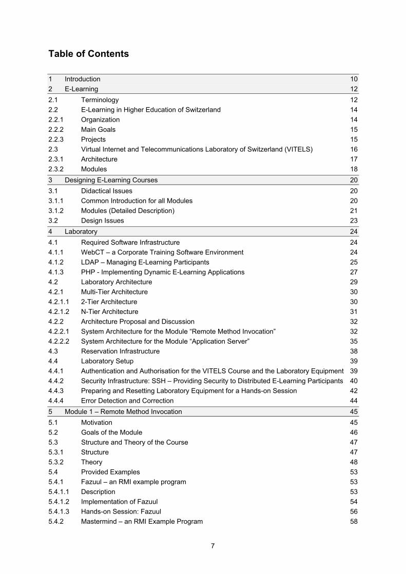
Table of Contents 1 Introduction 10 2 E-Learning 12 2.1 Terminology 12 2.2 E-Learning in Higher Education of Switzerland 14 2.2.1 Organization 14 2.2.2 Main Goals 15 2.2.3 Projects 15 2.3 Virtual Internet and Telecommunications Laboratory of Switzerland (VITELS) 16 2.3.1 Architecture 17 2.3.2 Modules 18 3 Designing E-Learning Courses 20 3.1 Didactical Issues 20 3.1.1 Common Introduction for all Modules 20 3.1.2 Modules (Detailed Description) 21 3.2 Design Issues 23 4 Laboratory 24 4.1 Required Software Infrastructure 24 4.1.1 WebCT – a Corporate Training Software Environment 24 4.1.2 LDAP – Managing E-Learning Participants 25 4.1.3 PHP - Implementing Dynamic E-Learning Applications 27 4.2 Laboratory Architecture 29 4.2.1 Multi-Tier Architecture 30 4.2.1.1 2-Tier Architecture 30 4.2.1.2 N-Tier Architecture 31 4.2.2 Architecture Proposal and Discussion 32 4.2.2.1 System Architecture for the Module “Remote Method Invocation” 32 4.2.2.2 System Architecture for the Module “Application Server” 35 4.3 Reservation Infrastructure 38 4.4 Laboratory Setup 39 4.4.1 Authentication and Authorisation for the VITELS Course and the Laboratory Equipment 39 4.4.2 Security Infrastructure: SSH – Providing Security to Distributed E-Learning Participants 40 4.4.3 Preparing and Resetting Laboratory Equipment for a Hands-on Session 42 4.4.4 Error Detection and Correction 44 5 Module 1 – Remote Method Invocation 45 5.1 Motivation 45 5.2 Goals of the Module 46 5.3 Structure and Theory of the Course 47 5.3.1 Structure 47 5.3.2 Theory 48 5.4 Provided Examples 53 5.4.1 Fazuul – an RMI example program 53 5.4.1.1 Description 53 5.4.1.2 Implementation of Fazuul 54 5.4.1.3 Hands-on Session: Fazuul 56 5.4.2 Mastermind – an RMI Example Program 58
8
5.4.2.1 Description 58 5.4.2.2 Implementation of Mastermind 59 5.4.2.3 Hands-on Session: Mastermind 61 6 Module 2 – Application Server 66 6.1 Motivation 66 6.2 Goals of the Module 67 6.3 Theory and Structure of the Course 67 6.3.1 Structure of the Course 68 6.3.2 Introduction to Java 2 Platform, Enterprise Edition (J2EE) 68 6.3.3 Architectural Overview 69 6.3.3.1 Object Model 70 6.3.3.2 Deployment Descriptor 71 6.3.3.3 Client 72 6.3.4 Developing Beans 73 6.3.4.1 Session Beans 74 6.3.4.2 Entity Beans 76 6.3.4.3 The Primary Key 77 6.3.5 Persisting and Querying Data 78 6.3.5.1 Container Managed Persistence (CMP) for Entity Beans 78 6.3.5.2 Query Entity Beans 81 6.3.6 Services 82 6.3.6.1 Naming 82 6.3.6.2 Transaction 82 6.3.6.3 Security 83 6.4 Provided examples 84 6.4.1 The Application Server 84 6.4.2 The Client for the Bank Examples 84 6.4.3 Scenario 1: The Bank Teller as a Stateless Session Bean 85 6.4.3.1 Description 85 6.4.3.2 Implementation 85 6.4.4 Scenario 2: The Bank Teller as a Stateful Session Bean 87 6.4.4.1 Description 87 6.4.5 Scenario 3: Customer and Account as Entity Beans 91 6.4.5.1 Description 91 6.4.5.2 Implementation 91 6.4.6 Scenario 4: Deployment Descriptor 94 6.4.7 Scenario 5: Developing an Entity Bean 96 7 Related Work 100 7.1 Authentication, Authorization and Resource Reservation for Distributed Laboratories 100 7.2 Internetportal für Computernetz-Praktika 100 7.3 The Virtual Internet and Telecommunications Laboratory of Switzerland 100 7.4 Architectural Issues of a Remote Network Laboratory 101 7.5 Didactical Issues of a Remote Network Laboratory 101 7.6 VITELS, Didactics and Design Guide 101 8 Discussion and Conclusions 102 9 Outlook 103 List of Figures 105
9
Listings 107 Abbreviations 108 Glossary 110 Bibliography 113

10
1 Introduction
The area of distributed systems is a well established field of research in computer science. There are two major reasons why the subject “distributed systems” is part of standard curricula of higher education for Information Technology (IT) professionals, i.e. in curricula for master diploma at universities. First, the theory of distributed systems is one of the cornerstones of computer science and IT professionals with a higher education should, therefore, at least have a basic understanding of its theory and a minimal experience in applying modern concepts of distributed systems. Second, important employers in the field of financial services, government or the IT industry, expect IT professionals to successfully apply concepts of distributed systems in their daily work. Distributed systems are the dominant architectural style for today’s information systems. Since the early seventies, the then predominant architectural style of centralized monolithic applications became less and less important in favour of the more flexible architectural style of distributed systems. This change in the architectural style was initially motivated by technological progress in networking and computer architecture. This technological progress provided the base for IT systems being built up from geographically distributed, interconnected and possibly heterogeneous computing nodes. This evolution was further supported with the advent of object-oriented computing in the eighties, which led to the architectural style of distributed object systems, as well as with the advent of the World Wide Web in the nineties. Lately, the concept of component based software engineering has influenced the field of distributed systems. Computer scientists recommend that software applications be split into software components, i.e. individually identifiable, replaceable and deployable units of software which would be hosted at runtime by dedicated component execution environments. The IT industry was quick to adopt this concept which led to the specification of J2EE Application Server and the component model Enterprise Java Bean (EJB), both widely used technologies for implementing distributed systems on the Java platform. Clearly, there is a need to teach both the theory and concepts of distributed systems and the applied technologies for building distributed systems. The need for the former is given by the relevance of distributed computing in contemporary computer science and by the importance it has in application and system engineering. It is advisable to teach the latter, because current work environments require IT professionals to be familiar with these technologies. Furthermore, hands-on experience with these technologies will help students to understand the conceptual and theoretical issues in the field of distributed systems. The group “Computer Networks and Distributed Systems” (in German: Rechnernetze und Verteilte Systeme, RVS) a research group of the Institute of Computer Science and Applied Mathematics (IAM) at the University of Bern is the leading party in the Virtual Internet and Telecommunications Laboratory of Switzerland (VITELS). The major goal of this project is to provide a set of structured online courses covering topics in the area of telecommunications and computer science. At the beginning of 2003, four modules were available for students on the common VITELS platform. These modules already cover fundamental topics required for
11
distributed systems, i.e. Internet Protocol (IP) network configuration, IP security, socket programming, or remote procedure calls. But in particular, two important subjects of distributed object computing, “Remote Method invocation” (RMI) and “Application Server”, were missing. In this diploma thesis, the gap in the VITELS course portfolio is closed. Two modules have been prepared for the VITELS platform: (1) a module about remote method invocation (see chapter 5) and a module about application servers (see chapter 6). A major requirement of the VITELS project is to provide a laboratory environment accessible over the Internet and where real-world scenarios can be tested. The preparation of hands-on sessions for courses about distributed systems poses some problems specific to the subject. One problem is to provide an environment in which real-world scenarios for building distributed systems can be implemented. In order to simulate real-world scenarios like implementing and deploying a distributed application, a network of distributed computing nodes, or looking up and addressing a remote component on a distributed computing node, a realistic laboratory environment should consist of several computing nodes connected to a network. If these scenarios were simulated on a single computer, students would fail to realize the special conditions of a truly distributed environment. This thesis addresses the specific problems of providing hands-on sessions for distributed systems. In Chapter 4, it discusses alternative architectures for the laboratory environment and proposes a system architecture suitable for providing practical tutorials. Section 5.4 and Section 6.4 give examples of hands-on sessions for the subject of Remote Method Invocation and the subject of Application Servers. The structure of this thesis is as follows: The second chapter introduces the subject of e-learning. It explains reasons why students should use a distance learning course to acquire knowledge instead of working in real laboratories at the university. E-learning in higher education of Switzerland as well as the VITELS project are explained in detail. The third chapter emphasises the need of a didactics and design guide and summarizes the content of an existing guide. The fourth chapter describes the infrastructure of the laboratory environment, such as the required software infrastructure, the laboratory architecture, the reservation infrastructure and the laboratory setup for both e-learning modules. Chapter five and six present the developed modules. A motivation for each subject is given, the goals are described and the theory of each topic is summarized. Chapter 8 and chapter 9 conclude this work and give a short outlook.
12
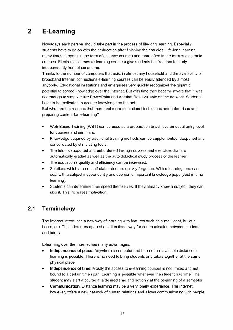
2 E-Learning
Nowadays each person should take part in the process of life-long learning. Especially students have to go on with their education after finishing their studies. Life-long learning many times happens in the form of distance courses and more often in the form of electronic courses. Electronic courses (e-learning courses) give students the freedom to study independently from place or time. Thanks to the number of computers that exist in almost any household and the availability of broadband Internet connections e-learning courses can be easily attended by almost anybody. Educational institutions and enterprises very quickly recognized the gigantic potential to spread knowledge over the Internet. But with time they became aware that it was not enough to simply make PowerPoint and Acrobat files available on the network. Students have to be motivated to acquire knowledge on the net. But what are the reasons that more and more educational institutions and enterprises are preparing content for e-learning? • Web Based Training (WBT) can be used as a preparation to achieve an equal entry level
for courses and seminars. • Knowledge acquired by traditional training methods can be supplemented, deepened and
consolidated by stimulating tools. • The tutor is supported and unburdened through quizzes and exercises that are
automatically graded as well as the auto didactical study process of the learner. • The education’s quality and efficiency can be increased. • Solutions which are not self-elaborated are quickly forgotten. With e-learning, one can
deal with a subject independently and overcome important knowledge gaps (Just-in-time-learning).
• Students can determine their speed themselves: If they already know a subject, they can skip it. This increases motivation.
2.1 Terminology
The Internet introduced a new way of learning with features such as e-mail, chat, bulletin board, etc. Those features opened a bidirectional way for communication between students and tutors. E-learning over the Internet has many advantages: • Independence of place: Anywhere a computer and Internet are available distance e-
learning is possible. There is no need to bring students and tutors together at the same physical place.
• Independence of time: Mostly the access to e-learning courses is not limited and not bound to a certain time span. Learning is possible whenever the student has time. The student may start a course at a desired time and not only at the beginning of a semester.
• Communication: Distance learning may be a very lonely experience. The Internet, however, offers a new network of human relations and allows communicating with people

13
“spread all over the world”. It provides a variety of tools to connect a learner with the tutor or other students.
• Individuality: With e-learning, the courses can be adapted to individual needs and goals more easily than in traditional education (seminar and courses). “Non-linear-learning” - which means learning does not occur in a neat sequence of events - is possible: the learner may repeat a chapter as many times as needed to understand the material, other chapters may be skipped.
• Interactivity: Interactive elements can be integrated into multimedia documents to encourage student interaction with learning materials and facilitate the assimilation of information [34]. An example is the feature “Question and answer” - where students are asked a question and must submit an answer (e.g. multiple choice). The interactive system can then respond and tell students if the answer is correct and explain the correct answer. Another feature is “drag and drop”: Objects can be selected with the mouse, dragged and dropped to construct images and objects on the screen.
• Multimedia: The Internet offers a great variety of interactive features, such as videos, audio images and animations. Reader/viewers will be able to pick and choose what they want to watch or hear at any time.
There is no widely accepted or canonical definition for e-learning. Here are five definitions from various authors [26]: • “The convergence of the Internet and learning, or Internet-enabled learning.” • “The uses of network technologies to create, foster, deliver, and facilitate learning,
anytime and anywhere.” • “The delivery of individualized, comprehensive, dynamic learning content in real time,
aiding the development of communities of knowledge, linking learners and practitioners with experts.”
• “A phenomenon that delivers accountability, accessibility, and opportunity allowing people and organizations to keep up with the rapid changes that define the Internet world.”
• “A force that gives people and organizations the competitive edge to allow them to keep ahead of the rapidly changing global economy.”
Recapitulating, e-learning is a new way of distance learning, usually from home or from any conveniently located off-campus place, supported by new technologies to acquire knowledge at any place and at any time wherever a computer is available. The difference to conventional learning is that the student acquires the material to learn all alone using digital devices such as the Internet (online) or CD-ROM (offline).
14
2.2 E-Learning in Higher Education of Switzerland
In 1999, the Swiss ministry of Education and Science founded a project called Swiss Virtual Campus (SVC). The purpose of this project is to enable the Higher Education Institutions (IHE) to integrate the new Information and Communication Technologies (ICT) and to combine new learning methods with ICT services. The project promotes learning over the Internet at university level with high-quality teaching materials and methods. The following sections give an overview of the SVC organisation, providing a description of the project as well as its main objectives.
2.2.1 Organization
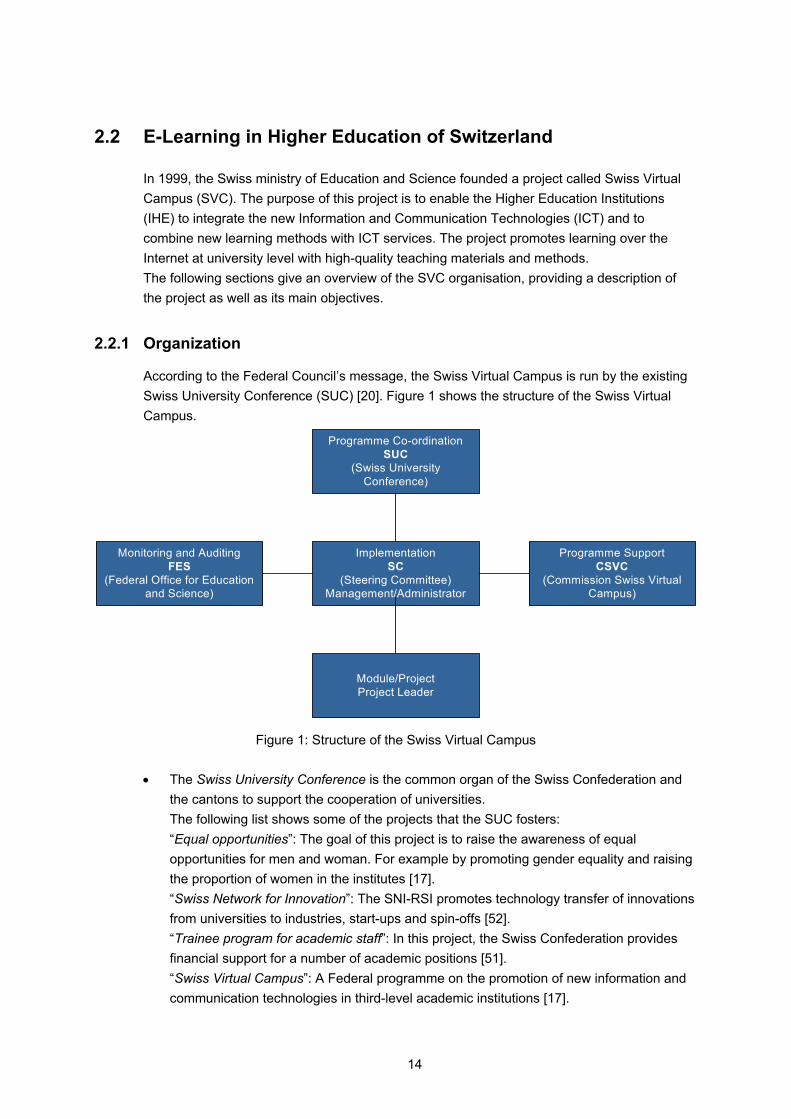
According to the Federal Council’s message, the Swiss Virtual Campus is run by the existing Swiss University Conference (SUC) [20]. Figure 1 shows the structure of the Swiss Virtual Campus.
Programme Co-ordinationSUC
(Swiss UniversityConference)
ImplementationSC
(Steering Committee)Management/Administrator
Programme SupportCSVC
(Commission Swiss VirtualCampus)
Monitoring and AuditingFES
(Federal Office for Educationand Science)
Module/ProjectProject Leader
Figure 1: Structure of the Swiss Virtual Campus
• The Swiss University Conference is the common organ of the Swiss Confederation and
the cantons to support the cooperation of universities. The following list shows some of the projects that the SUC fosters: “Equal opportunities”: The goal of this project is to raise the awareness of equal opportunities for men and woman. For example by promoting gender equality and raising the proportion of women in the institutes [17]. “Swiss Network for Innovation”: The SNI-RSI promotes technology transfer of innovations from universities to industries, start-ups and spin-offs [52]. “Trainee program for academic staff”: In this project, the Swiss Confederation provides financial support for a number of academic positions [51]. “Swiss Virtual Campus”: A Federal programme on the promotion of new information and communication technologies in third-level academic institutions [17].
15
The federal council delegated the management of the SVC programme to the Swiss university conference. The SUC makes the final decisions regarding the financing of projects and mandates recommended by the steering committee.
• The Steering Committee (SC) is an execution organ; it develops the financial plan, which needs to be approved by the SUC. The committee also evaluates the incoming proposals, selects the projects to be supported, negotiates the financing of the individual projects and mandates, evaluates the projects [20].
• “The SVC Commission” was founded to help the universities to understand their role and involvement in the programme [42]. It makes preparatory work for the call for papers, like establishing contacts with interested parties from the university, cantonal, federal, and business communities.
• The Federal Office for Education and Science (FES) [18] is in charge of monitoring and reviewing the projects.
2.2.2 Main Goals
Bernard Levrat [41], the spiritual father of the SVC programme, wants the lectures with completely passive students to disappear [43]. "The idea is that the way in which knowledge is communicated should be attractive and thanks to interactivity more efficient ", he says. Another aim of the SVC programme is specified on the web page of The Swiss Federal Office for Professional Education and Technology [17]: The principal concrete aim of the programme is to develop accessible teaching modules through the Internet for basic and specialised study programmes, particularly for subjects that attract large numbers of students. The SVC itself was founded with three main goals in mind: (1) Improving the quality of student learning processes and strengthening interactive teaching (2) Strengthening the collaboration between the universities (3) Developing high-quality teaching materials and methods. With these goals in mind the SVC issued two tenders for SVC projects in 1999 and 2000.
2.2.3 Projects
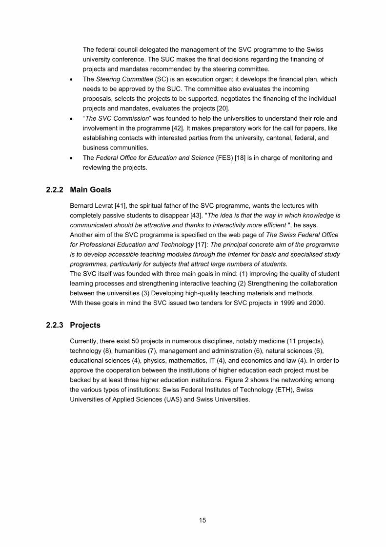
Currently, there exist 50 projects in numerous disciplines, notably medicine (11 projects), technology (8), humanities (7), management and administration (6), natural sciences (6), educational sciences (4), physics, mathematics, IT (4), and economics and law (4). In order to approve the cooperation between the institutions of higher education each project must be backed by at least three higher education institutions. Figure 2 shows the networking among the various types of institutions: Swiss Federal Institutes of Technology (ETH), Swiss Universities of Applied Sciences (UAS) and Swiss Universities.
16
25
7
5
4
3
6
0
Universities
Universities ofApplied Sciences(UAS)
Federal Institutes ofTechnology (ETHs)
Figure 2: Networking among the Higher Education Institutions
One of these projects lead by the University of Bern is the Virtual Internet and Telecommunications Laboratory of Switzerland [21].
2.3 Virtual Internet and Telecommunications Laboratory of Switzerland (VITELS)
Four Swiss universities (the Universities of Bern, Fribourg, Genève and Neuchâtel) and one engineering school (Fribourg) collaborate in the project Virtual Internet and Telecommunications Laboratory of Switzerland (VITELS). The project partners launched VITELS because they have common interests in developing e-learning resources for their students. A common interest is the sharing of knowledge. With VITELS, each university can concentrate their efforts on few topics but give their students access to the topics of the partner universities. Each university has to spend less money than before (w/o VITELS) but can offer a wider spectrum of interesting and well maintained e-learning modules. Another interest is given by the fact that students should become familiar with e-learning, because e-learning will become more and more important during their professional career, after their graduation from university. For Information Technology (IT) professionals, e-learning is especially useful because constant learning is crucial for professionals in information technologies and because significant portions of product and technology based training and education can be provided as e-learning resources.
17
2.3.1 Architecture
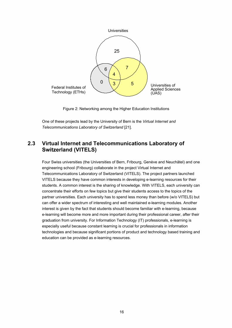
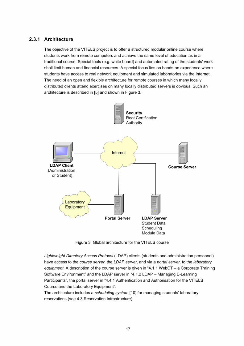
The objective of the VITELS project is to offer a structured modular online course where students work from remote computers and achieve the same level of education as in a traditional course. Special tools (e.g. white board) and automated rating of the students’ work shall limit human and financial resources. A special focus lies on hands-on experience where students have access to real network equipment and simulated laboratories via the Internet. The need of an open and flexible architecture for remote courses in which many locally distributed clients attend exercises on many locally distributed servers is obvious. Such an architecture is described in [5] and shown in Figure 3.
Course ServerLDAP Client(Administration
or Student)
Internet
Portal Server
LaboratoryEquipment
LDAP ServerStudent DataSchedulingModule Data
SecurityRoot CertificationAuthority
Figure 3: Global architecture for the VITELS course
Lightweight Directory Access Protocol (LDAP) clients (students and administration personnel) have access to the course server, the LDAP server, and via a portal server, to the laboratory equipment. A description of the course server is given in “4.1.1 WebCT – a Corporate Training Software Environment” and the LDAP server in “4.1.2 LDAP – Managing E-Learning Participants”, the portal server in “4.4.1 Authentication and Authorisation for the VITELS Course and the Laboratory Equipment”. The architecture includes a scheduling system [10] for managing students’ laboratory reservations (see 4.3 Reservation Infrastructure).
18
2.3.2 Modules
To this time, VITELS offers six modules. This section gives a short description of the following modules: “Simulation of Internet Protocol (IP) Network Configuration”, “IP Security”, “Firewall Management”, and “Sockets and Remote Procedure Calls (RPC)”. Chapter 5 and chapter 6 provide detailed descriptions of the “Remote Method Invocation” (RMI)-module and the "Application Server”-module. Simulation of IP Network Configuration introduces basic networking concepts, the most common local area network technologies, the Internet protocol as well as the functioning and the operational area of the most common network components. In a simulation, the user optimizes routing table entries, adds and corrects interfaces and routing table configurations. In addition, an emulation is used to help students to layout, configure and validate a network consisting of multiple routers. At the end, students know how to set up IP networks, especially the selection of appropriate address ranges and the configuration of interfaces and routes.
Logo 1: Simulation of IP Network Configuration
IP Security presents the basic security concepts of today’s Internet. It includes theoretical modules about discovering the world of Virtual Private Networks (VPN) as well as security issues due to hackers. In the hands-on session, students are asked to configure two different Cisco routers (2620 and 3620) and to set up the Routing Information Protocol (RIP). After a successful configuration, students have to establish a virtual private network tunnel between those two routers. In addition, students learn to use Tcpdump, to interpret the network dumps, to generate and analyze network traffic, and to perform bandwidth measurements in IP networks by applying a measurement tool on generated traffic with and without encryption.
Logo 2: IP Security
19
Firewall Management introduces firewall concepts of today's Internet. The module explains the mechanisms of packet filtering, Network Address Translation (NAT) possibilities, the basic concepts of packet filter rule base generation and firewall architecture and their different modes. It shows how to protect a network from attacks from the Internet by implementing a firewall. In the hands-on session, students have the possibility to fully configure a Netscreen 5XP firewall and to set up network address translation. In a further step, they completely set up and configure the firewall in a small business environment which consists of three clients, a mail, a web and a DNS server.
Logo 3: Firewall Management
Sockets and Remote Procedure Calls explains a fundamental structure in many computer networks: a client-server relationship. In the first part of this module, students are introduced to socket programming, an intuitive way to develop applications that enable computers to use TCP/IP communication, as well as many other protocols (e.g. UDP, ICMP, etc.). In the second part of this module, the concept of remote procedure calls is introduced. This is a very early example of a client/server architecture that has its own specification language. In the practical, part students have the possibility to develop their own socket and RPC applications.
Logo 4: Sockets and RPC
Other modules are planned or under development: Linux Systems Installation and Configuration teaches the installation and configuration of Linux computers from scratch. Performance Evaluation in Real IP Networks explains theoretical and practical aspects of performance metrics in real IP networks. Client/Server Programming discusses the theoretical and practical aspects of the client/server model. In the Protocol Analysis-module, students enter the field of the layered Internet protocol [14].
20
3 Designing E-Learning Courses
An e-learning course mostly consists of several modules that are equivalent to book chapters. A detailed content description, based upon the predefined course goals and the definition of the target group, need to be specified before starting with the implementation. Before an e-learning course can be designed, course designers should understand how their targeted students learn and how they acquire and retain skills or how they access information. Course modules must have an identical structure in order to allow an easy navigation. Each course module should be designed and developed in such a way that students are provided with interesting interactive learning material, enhanced with didactical elements. Course participants should be informed about the goals and procedures to be reached. The course provider should furthermore give a description of the different support forms. Because no tutor is permanently available, self-evaluation tools such as self tests and quizzes have to be offered to students to test their success. A self test is a test with multiple choice questions where students receive the answer immediately. This helps to minimize the theoretical work if the test is done before reading through the theory. Students may use this instrument to check what they have learned and to find knowledge gaps (students gave wrong answers). For every answered question, the learning program points out the chapter to be repeated, recommends further readings and/or describes the way to find the correct answer. In a quiz, students must answer different types of questions (e.g. multiple choice questions, yes or no questions, essay questions). In contrast to the self test, the answers are not immediately given, but are sent to and graded by a tutor. The evaluation of the quiz helps tutors to discover missing theory parts or to discover lazy students [7]. A schedule helps students to plan the time they are going to spend in the course. Students like to communicate and to see if other fellow students are online at the same time. Therefore, communication tools should be offered and actively integrated into the learning content. A course development guide [7] for the VITELS project helps the topic experts to develop valuable content efficiently. No time will be lost with didactic or layout issues. The guide enables VITELS module designers to create a uniform and interesting course with identically structured and designed modules. The document is divided into two parts: the didactical and the design part. In general, the guide describes a constructivist approach for a hands-on session oriented e-learning course. It can be adapted (i.e. can be a base) for other courses than VITELS.
3.1 Didactical Issues
The didactical part of the guide explains the course structure, why certain chapters were chosen and also provides specific implementation rules [7]. It was developed with the support of Technologies de Formation et Apprentissage [28].
3.1.1 Common Introduction for all Modules
The task of the „General Introduction and FAQ“ is to avoid reiterations in the various VITELS modules. It provides information that is valid throughout the whole course and in each module. It points out the goals of the learning platform (mission), explains the VITELS way of teaching

21
(pedagogical approach), gives students a short overview of the module structure, presents the module designers, introduces traditional students into the new way of studying, explains the laboratory reservation system that is needed to reserve the laboratory equipment of some VITELS modules (see 4.3 Reservation Infrastructure), provides links that are not module specific, explains students how to record their progress, motivates students to use the discussion board, shows students how to get help and last but not least points them to “Frequently Asked Questions”, which gives answers to questions that concern all modules.
3.1.2 Modules (Detailed Description)
In this section the designers are provided a description on how to create and follow a uniform course structure throughout their course module. All VITELS modules are split into four sections. To give students a better orientation, each section has its own colour. Figure 4 shows the layout of the e-learning modules:
Figure 4: Layout for e-learning Modules [24]
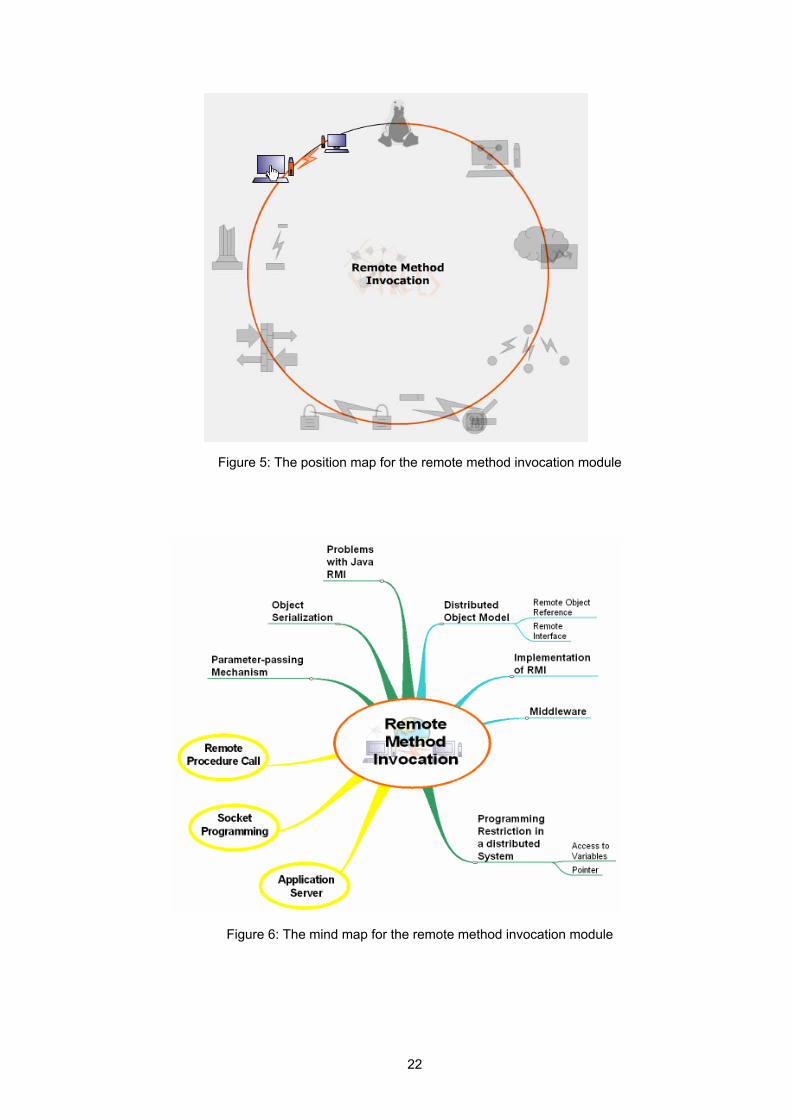
In the Introduction students get a welcome message and a very short introduction to the module. The main goals of this section are described as informing students on what they are going to learn. In a further step, students must write down their expectations of the course. The position to other modules is reflected in a Position Map (Figure 5), and in a Mind Map (Figure 6) the associations are depicted. The FAQ gives answers to questions concerning the module topic.
22
Figure 5: The position map for the remote method invocation module
Figure 6: The mind map for the remote method invocation module
23
In the pre laboratory section (Theory), the students are introduced to the topic of the module. The theoretical part prepares students for the hands-on session. After the theoretical part, a list of required and recommended readings is offered. In a “Personal Synthesis” students get the possibility to express what they have learned and experienced. Students use a tool called self test to find out what they should read in addition to pass the quiz. The laboratory section (Knowledge Application/Exploration), is the most important section of each module. Students apply what they have learned in the theory section: they solve problems with either simulations, emulations or they work on real devices. In the post laboratory section (Prove Your Knowledge and Skills), students write a personal synthesis. In a short essay, they explain what they did in the laboratory section. They then have to pass a graded final quiz to see what they have really learned.
3.2 Design Issues
Each participating university develops and maintains its modules within its own laboratory environment, but allows remote students to access and use the laboratory infrastructure via Internet technologies. The entire course must appear to the user as being homogeneous, although it is distributed over several locations in Switzerland [5]. The second part of the guide ensures that all the modules are homogeneous. It explains the visual design, the page layout (as well as the corresponding design and layout mechanisms) and the course platform settings.

24
4 Laboratory
The VITELS architecture, already described in “2.3.1 Architecture” is an open architecture for remote courses in which geographically distributed clients attend exercises on geographically distributed servers. The existing software infrastructure is explained in the first section (4.1). The next sections discuss the controlling of additional hardware resources (4.2) and the scheduling system (4.3). Finally, in section “4.4 Laboratory Setup”, different aspects like authentication and security are discussed.
4.1 Required Software Infrastructure
This section explains WebCT, the platform to integrate the e-learning modules, the Lightweight Directory Access Protocol server, a directory server integrated in the current architecture for user and data management as well as for scheduling functions, and the Hypertext Preprocessor (PHP), a scripting language.
4.1.1 WebCT – a Corporate Training Software Environment
Individual modules are integrated on a common platform WebCT which acts as unifying portal (single point of entry) for students and also as common management platform for course administrators. WebCT is a Content Management System (CMS), which is tailored to the needs of higher-education and helps providing the course content. It enables course creators to tag, store, reuse, reassemble and share learning objects (assessments, lessons, lectures, tutorials, activities, simulations, graphics, multimedia, and other intellectual assets) [22]. It also offers the possibility to track how content is used, and by whom. As there is mostly no tutor or other student available to whom one can ask questions, WebCT offers many helpful tools such as e-mail, forum, whiteboard, chat room etc. to communicate. Students may also use the discussion board to ask questions to the tutor or to other students if they can rely on receiving an answer within a short time. WebCT offers multiple-choice questions, yes or no questions and text questions. Students find definitions, phrases and acronyms as well as computer related words in the integrated online glossary. When studying a paper hardcopy, students are used to take notes; the e-learning platform opens an additional browser window where students can enter their notes. Figure 7 shows a list of notes a student has already taken.

25
Figure 7: WebCT notes - list
4.1.2 LDAP – Managing E-Learning Participants
The e-learning modules offered by the VITELS project are provided to a closed user group which typically consists of students of one course/class. The project’s modules are restricted to a closed user group for the following reasons: • Limited resources. The e-learning resources (available computers) for laboratory
sessions are limited. Resources have to be reserved for and assigned to a specific student for a specific period of time. Each student therefore needs to be known in advance.
• Security. E-learning resources like dedicated computers could be misused for activities which are not part of the practical tutorials.
• Credit administration. Credits earned with the completion of practical tutorials can only be assigned to known users.
The users which are granted access to the e-learning resources vary over time. A user administration subsystem ensures that at any time • the right to access can be revoked from some users • the right to access can be granted to some users • a new user account can be created • an existing user account can be modified • an existing user account can be deleted
Administrative data about users is kept in a directory on the user administration system of the “VITELS” platform. The purpose of electronic directories is to provide names, locations and
26
other information about people and organizations [15]. The directory entries are organized in hierarchical name space capable of supporting large amounts of information. The data can be manipulated using the standard lightweight directory access protocol that defines a standard method for accessing and updating information in a directory.
Lightweight Directory Access Protocol
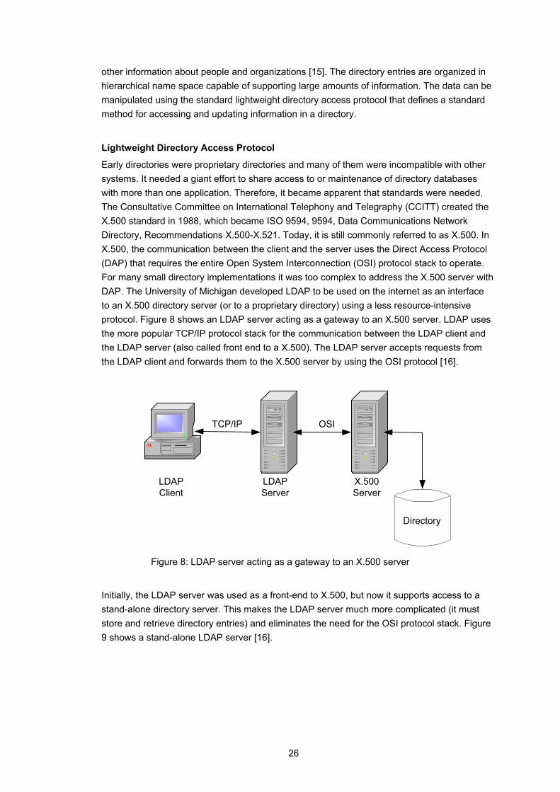
Early directories were proprietary directories and many of them were incompatible with other systems. It needed a giant effort to share access to or maintenance of directory databases with more than one application. Therefore, it became apparent that standards were needed. The Consultative Committee on International Telephony and Telegraphy (CCITT) created the X.500 standard in 1988, which became ISO 9594, 9594, Data Communications Network Directory, Recommendations X.500-X.521. Today, it is still commonly referred to as X.500. In X.500, the communication between the client and the server uses the Direct Access Protocol (DAP) that requires the entire Open System Interconnection (OSI) protocol stack to operate. For many small directory implementations it was too complex to address the X.500 server with DAP. The University of Michigan developed LDAP to be used on the internet as an interface to an X.500 directory server (or to a proprietary directory) using a less resource-intensive protocol. Figure 8 shows an LDAP server acting as a gateway to an X.500 server. LDAP uses the more popular TCP/IP protocol stack for the communication between the LDAP client and the LDAP server (also called front end to a X.500). The LDAP server accepts requests from the LDAP client and forwards them to the X.500 server by using the OSI protocol [16].
LDAPClient
TCP/IP OSI
LDAPServer
X.500Server
Directory
Figure 8: LDAP server acting as a gateway to an X.500 server
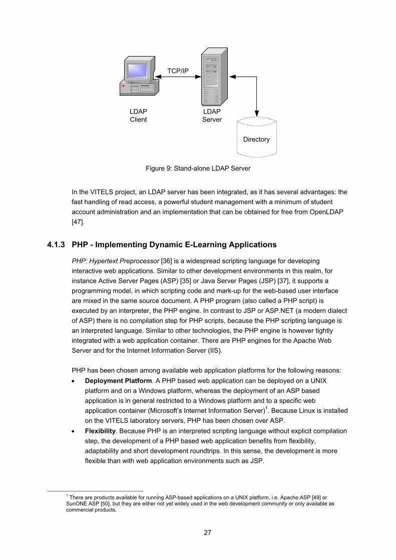
Initially, the LDAP server was used as a front-end to X.500, but now it supports access to a stand-alone directory server. This makes the LDAP server much more complicated (it must store and retrieve directory entries) and eliminates the need for the OSI protocol stack. Figure 9 shows a stand-alone LDAP server [16].
27
LDAPClient
TCP/IP
LDAPServer
Directory
Figure 9: Stand-alone LDAP Server
In the VITELS project, an LDAP server has been integrated, as it has several advantages: the fast handling of read access, a powerful student management with a minimum of student account administration and an implementation that can be obtained for free from OpenLDAP [47].
4.1.3 PHP - Implementing Dynamic E-Learning Applications
PHP: Hypertext Preprocessor [36] is a widespread scripting language for developing interactive web applications. Similar to other development environments in this realm, for instance Active Server Pages (ASP) [35] or Java Server Pages (JSP) [37], it supports a programming model, in which scripting code and mark-up for the web-based user interface are mixed in the same source document. A PHP program (also called a PHP script) is executed by an interpreter, the PHP engine. In contrast to JSP or ASP.NET (a modern dialect of ASP) there is no compilation step for PHP scripts, because the PHP scripting language is an interpreted language. Similar to other technologies, the PHP engine is however tightly integrated with a web application container. There are PHP engines for the Apache Web Server and for the Internet Information Server (IIS). PHP has been chosen among available web application platforms for the following reasons: • Deployment Platform. A PHP based web application can be deployed on a UNIX
platform and on a Windows platform, whereas the deployment of an ASP based application is in general restricted to a Windows platform and to a specific web application container (Microsoft’s Internet Information Server)1. Because Linux is installed on the VITELS laboratory servers, PHP has been chosen over ASP.
• Flexibility. Because PHP is an interpreted scripting language without explicit compilation step, the development of a PHP based web application benefits from flexibility, adaptability and short development roundtrips. In this sense, the development is more flexible than with web application environments such as JSP.
1 There are products available for running ASP-based applications on a UNIX platform, i.e. Apache:ASP [49] or SunONE ASP [50], but they are either not yet widely used in the web development community or only available as commercial products.
28
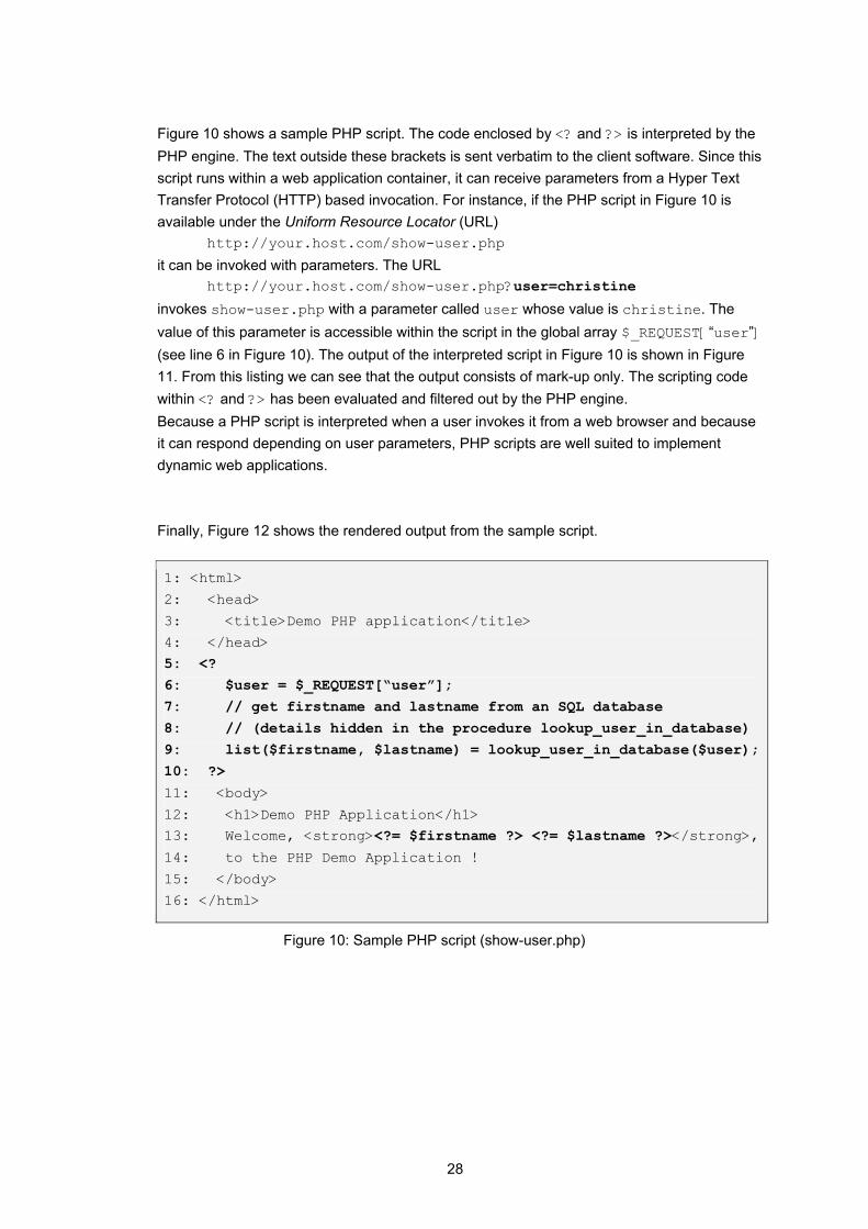
Figure 10 shows a sample PHP script. The code enclosed by <? and ?> is interpreted by the PHP engine. The text outside these brackets is sent verbatim to the client software. Since this script runs within a web application container, it can receive parameters from a Hyper Text Transfer Protocol (HTTP) based invocation. For instance, if the PHP script in Figure 10 is available under the Uniform Resource Locator (URL)
http://your.host.com/show-user.php
it can be invoked with parameters. The URL http://your.host.com/show-user.php?user=christine
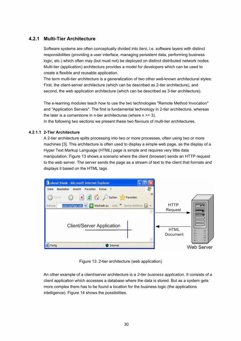
invokes show-user.php with a parameter called user whose value is christine. The value of this parameter is accessible within the script in the global array $_REQUEST[“user”] (see line 6 in Figure 10). The output of the interpreted script in Figure 10 is shown in Figure 11. From this listing we can see that the output consists of mark-up only. The scripting code within <? and ?> has been evaluated and filtered out by the PHP engine. Because a PHP script is interpreted when a user invokes it from a web browser and because it can respond depending on user parameters, PHP scripts are well suited to implement dynamic web applications. Finally, Figure 12 shows the rendered output from the sample script.
1: <html>
2: <head>
3: <title>Demo PHP application</title>
4: </head> 5: <? 6: $user = $_REQUEST[“user”]; 7: // get firstname and lastname from an SQL database 8: // (details hidden in the procedure lookup_user_in_database) 9: list($firstname, $lastname) = lookup_user_in_database($user);10: ?>
11: <body>
12: <h1>Demo PHP Application</h1> 13: Welcome, <strong><?= $firstname ?> <?= $lastname ?></strong>,
14: to the PHP Demo Application !
15: </body>
16: </html>
Figure 10: Sample PHP script (show-user.php)
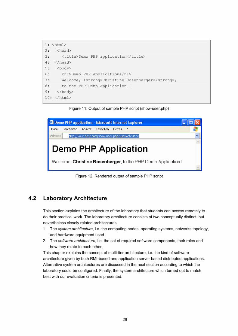
29
1: <html>
2: <head>
3: <title>Demo PHP application</title>
4: </head>
5: <body>
6: <h1>Demo PHP Application</h1>
7: Welcome, <strong>Christine Rosenberger</strong>,
8: to the PHP Demo Application !
9: </body>
10: </html>
Figure 11: Output of sample PHP script (show-user.php)
Figure 12: Rendered output of sample PHP script
4.2 Laboratory Architecture
This section explains the architecture of the laboratory that students can access remotely to do their practical work. The laboratory architecture consists of two conceptually distinct, but nevertheless closely related architectures: 1. The system architecture, i.e. the computing nodes, operating systems, networks topology,
and hardware equipment used. 2. The software architecture, i.e. the set of required software components, their roles and
how they relate to each other. This chapter explains the concept of multi-tier architecture, i.e. the kind of software architecture given by both RMI-based and application server based distributed applications. Alternative system architectures are discussed in the next section according to which the laboratory could be configured. Finally, the system architecture which turned out to match best with our evaluation criteria is presented.
30
4.2.1 Multi-Tier Architecture
Software systems are often conceptually divided into tiers, i.e. software layers with distinct responsibilities (providing a user interface, managing persistent data, performing business logic, etc.) which often may (but must not) be deployed on distinct distributed network nodes. Multi-tier (application) architecture provides a model for developers which can be used to create a flexible and reusable application. The term multi-tier architecture is a generalization of two other well-known architectural styles: First, the client-server architecture (which can be described as 2-tier architecture), and second, the web application architecture (which can be described as 3-tier architecture). The e-learning modules teach how to use the two technologies "Remote Method Invocation" and "Application Servers". The first is fundamental technology in 2-tier architecture, whereas the later is a cornerstone in n-tier architectures (where n >= 3). In the following two sections we present these two flavours of multi-tier architectures.
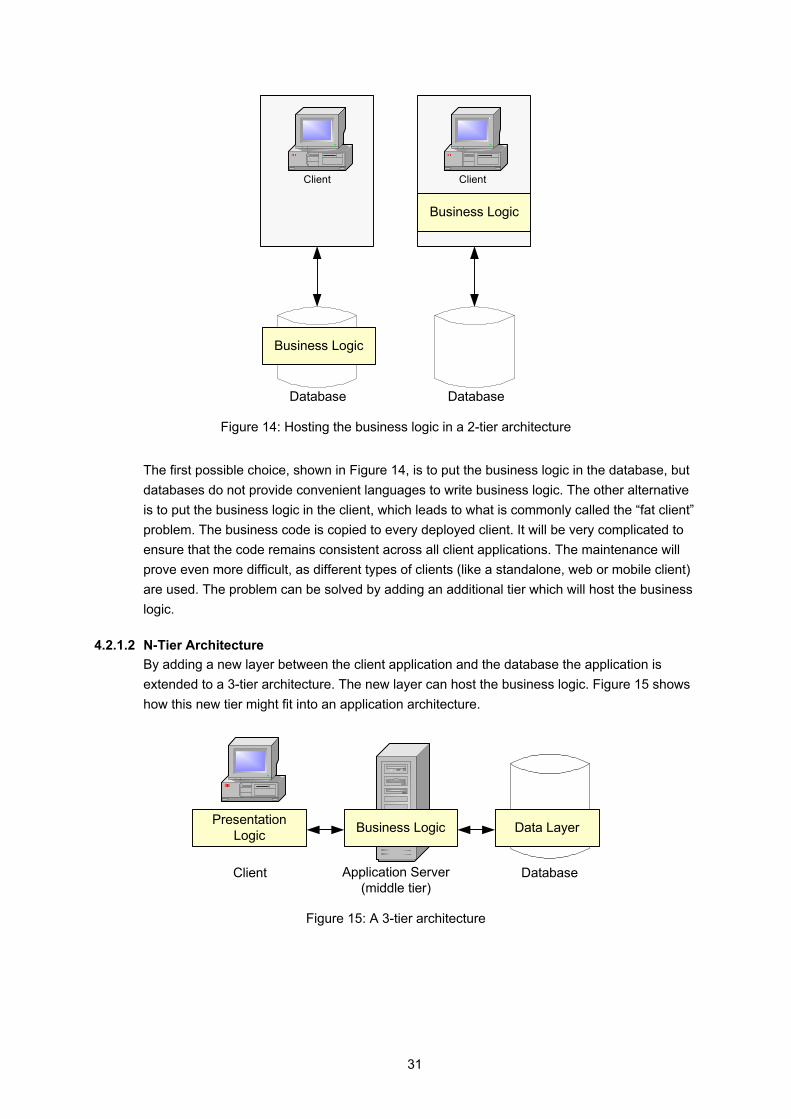
4.2.1.1 2-Tier Architecture A 2-tier architecture splits processing into two or more processes, often using two or more machines [3]. This architecture is often used to display a simple web page, as the display of a Hyper Text Markup Language (HTML) page is simple and requires very little data manipulation. Figure 13 shows a scenario where the client (browser) sends an HTTP request to the web server. The server sends the page as a stream of text to the client that formats and displays it based on the HTML tags.
Figure 13: 2-tier architecture (web application)
An other example of a client/server architecture is a 2-tier business application. It consists of a client application which accesses a database where the data is stored. But as a system gets more complex there has to be found a location for the business logic (the applications intelligence). Figure 14 shows the possibilities.
31
ClientClient
Business Logic
Business Logic
Database Database
Figure 14: Hosting the business logic in a 2-tier architecture
The first possible choice, shown in Figure 14, is to put the business logic in the database, but databases do not provide convenient languages to write business logic. The other alternative is to put the business logic in the client, which leads to what is commonly called the “fat client” problem. The business code is copied to every deployed client. It will be very complicated to ensure that the code remains consistent across all client applications. The maintenance will prove even more difficult, as different types of clients (like a standalone, web or mobile client) are used. The problem can be solved by adding an additional tier which will host the business logic.
4.2.1.2 N-Tier Architecture By adding a new layer between the client application and the database the application is extended to a 3-tier architecture. The new layer can host the business logic. Figure 15 shows how this new tier might fit into an application architecture.
Application Server(middle tier)
Business Logic
Database
PresentationLogic Data Layer
Client
Figure 15: A 3-tier architecture
32
The system is partitioned into three logical layers and every layer has different responsibilities: • The presentation logic resides in the client, dealing with the user interfaces and user
transactions. The technologies used here may be Visual Basic for a stand alone application. For a web application the client could use JSP, ASP or Java Applets.
• The business logic resides in the application server (middle tier), executing a part of the application logic to solve business problems. Typically, this layer is written in type-safe languages such as Java or C++.
• The data layer, on the backend, is used by the business logic layer to persist state permanently. The database is now isolated from the presentation layer. This way, the presentation is not related to the manipulation of data [1].
An application can be broken down into an n-tier application, by adding more layers to the architecture and by distributing the logic into these layers. (“n” is the number of distinct tiers used in the architecture). For example, the business logic tier in Figure 15 might be broken down into a business logic tier and a data access tier. N-tier systems are more complex and therefore more difficult to design and to implement than monolithic or 2-tier systems. In the hands-on session, students will have to develop client- and server programs. The following chapters discuss the different possibilities how and where to install the machines.
4.2.2 Architecture Proposal and Discussion
N-tier systems are more complex and therefore more difficult to design and to implement than monolithic or 2-tier systems. In the hands-on session, students will have to develop client- and server programs. This chapter discusses the different possibilities how and where to install the machines.
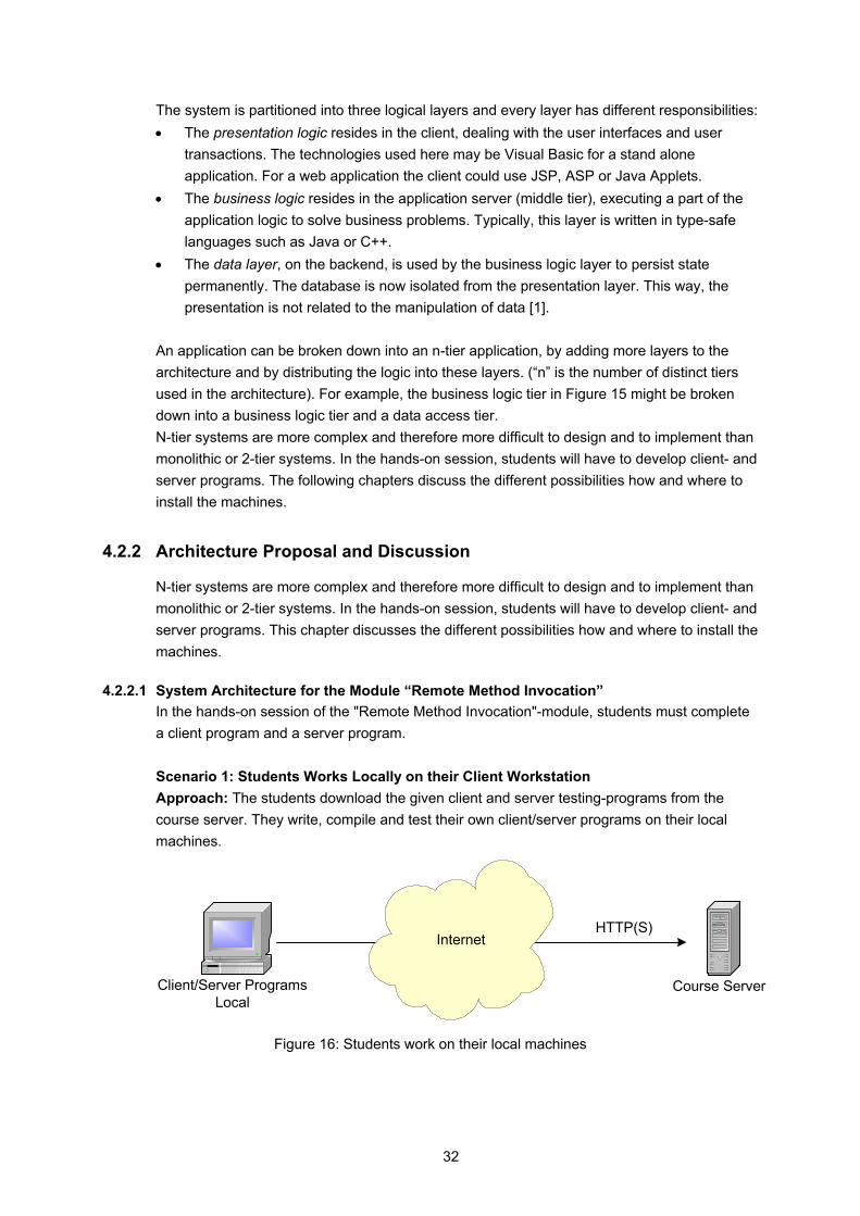
4.2.2.1 System Architecture for the Module “Remote Method Invocation” In the hands-on session of the "Remote Method Invocation"-module, students must complete a client program and a server program. Scenario 1: Students Works Locally on their Client Workstation Approach: The students download the given client and server testing-programs from the course server. They write, compile and test their own client/server programs on their local machines.
Course Server
HTTP(S)
Client/Server ProgramsLocal
Internet
Figure 16: Students work on their local machines
33
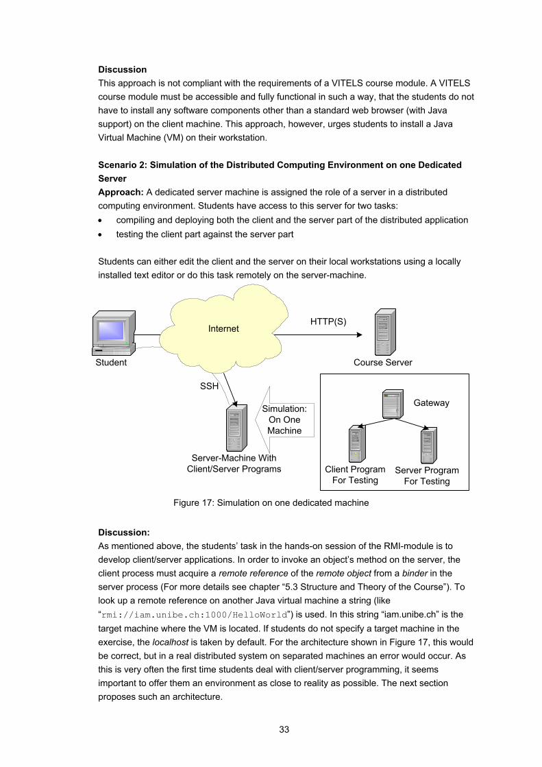
Discussion This approach is not compliant with the requirements of a VITELS course module. A VITELS course module must be accessible and fully functional in such a way, that the students do not have to install any software components other than a standard web browser (with Java support) on the client machine. This approach, however, urges students to install a Java Virtual Machine (VM) on their workstation. Scenario 2: Simulation of the Distributed Computing Environment on one Dedicated Server Approach: A dedicated server machine is assigned the role of a server in a distributed computing environment. Students have access to this server for two tasks: • compiling and deploying both the client and the server part of the distributed application • testing the client part against the server part Students can either edit the client and the server on their local workstations using a locally installed text editor or do this task remotely on the server-machine.
Course Server
HTTP(S)
Student
Internet
Server-Machine WithClient/Server Programs Client Program
For TestingServer Program
For Testing
Simulation:On OneMachine
Gateway
SSH
Figure 17: Simulation on one dedicated machine
Discussion: As mentioned above, the students’ task in the hands-on session of the RMI-module is to develop client/server applications. In order to invoke an object’s method on the server, the client process must acquire a remote reference of the remote object from a binder in the server process (For more details see chapter “5.3 Structure and Theory of the Course”). To look up a remote reference on another Java virtual machine a string (like “rmi://iam.unibe.ch:1000/HelloWorld”) is used. In this string “iam.unibe.ch” is the target machine where the VM is located. If students do not specify a target machine in the exercise, the localhost is taken by default. For the architecture shown in Figure 17, this would be correct, but in a real distributed system on separated machines an error would occur. As this is very often the first time students deal with client/server programming, it seems important to offer them an environment as close to reality as possible. The next section proposes such an architecture.
34
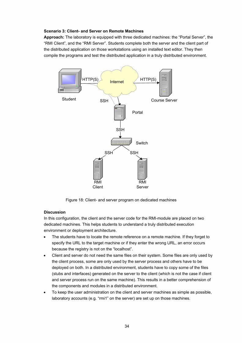
Scenario 3: Client- and Server on Remote Machines Approach: The laboratory is equipped with three dedicated machines: the “Portal Server”, the “RMI Client”, and the “RMI Server”. Students complete both the server and the client part of the distributed application on those workstations using an installed text editor. They then compile the programs and test the distributed application in a truly distributed environment.
HTTP(S)
Portal
Course ServerStudent
Switch
RMIClient
RMIServer
InternetHTTP(S)
SSH
SSH
SSH
SSH
Figure 18: Client- and server program on dedicated machines Discussion In this configuration, the client and the server code for the RMI-module are placed on two dedicated machines. This helps students to understand a truly distributed execution environment or deployment architecture. • The students have to locate the remote reference on a remote machine. If they forget to
specify the URL to the target machine or if they enter the wrong URL, an error occurs because the registry is not on the “localhost”.
• Client and server do not need the same files on their system. Some files are only used by the client process, some are only used by the server process and others have to be deployed on both. In a distributed environment, students have to copy some of the files (stubs and interfaces) generated on the server to the client (which is not the case if client and server process run on the same machine). This results in a better comprehension of the components and modules in a distributed environment.
• To keep the user administration on the client and server machines as simple as possible, laboratory accounts (e.g. “rmi1” on the server) are set up on those machines.
35
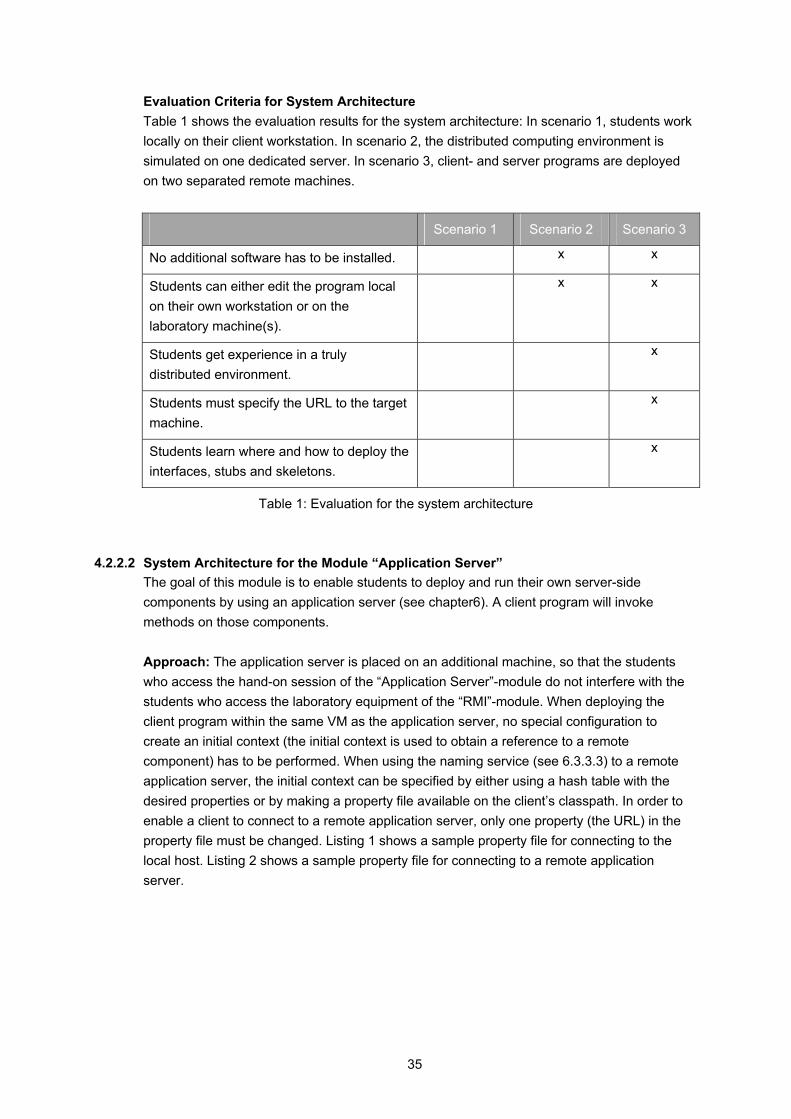
Evaluation Criteria for System Architecture Table 1 shows the evaluation results for the system architecture: In scenario 1, students work locally on their client workstation. In scenario 2, the distributed computing environment is simulated on one dedicated server. In scenario 3, client- and server programs are deployed on two separated remote machines.
Scenario 1 Scenario 2 Scenario 3
No additional software has to be installed. x x
Students can either edit the program local on their own workstation or on the laboratory machine(s).
x x
Students get experience in a truly distributed environment.
x
Students must specify the URL to the target machine.
x
Students learn where and how to deploy the interfaces, stubs and skeletons.
x
Table 1: Evaluation for the system architecture
4.2.2.2 System Architecture for the Module “Application Server” The goal of this module is to enable students to deploy and run their own server-side components by using an application server (see chapter6). A client program will invoke methods on those components. Approach: The application server is placed on an additional machine, so that the students who access the hand-on session of the “Application Server”-module do not interfere with the students who access the laboratory equipment of the “RMI”-module. When deploying the client program within the same VM as the application server, no special configuration to create an initial context (the initial context is used to obtain a reference to a remote component) has to be performed. When using the naming service (see 6.3.3.3) to a remote application server, the initial context can be specified by either using a hash table with the desired properties or by making a property file available on the client’s classpath. In order to enable a client to connect to a remote application server, only one property (the URL) in the property file must be changed. Listing 1 shows a sample property file for connecting to the local host. Listing 2 shows a sample property file for connecting to a remote application server.
36
java.naming.factory.initial=org.jnp.interfaces.NamingContextFactory java.naming.factory.url.pkgs=org.jboss.naming:org.jnp.interfaces java.naming.provider.url=localhost
Listing 1: The JNDI property file with the URL “localhost”
java.naming.factory.initial=org.jnp.interfaces.NamingContextFactory java.naming.factory.url.pkgs=org.jboss.naming:org.jnp.interfaces java.naming.provider.url=jnp://10.1.1.35
Listing 2: The JNDI property file with the URL “kif.unibe.ch”
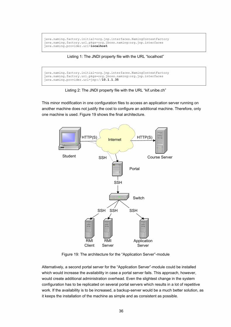
This minor modification in one configuration files to access an application server running on another machine does not justify the cost to configure an additional machine. Therefore, only one machine is used. Figure 19 shows the final architecture.
HTTP(S)
Portal
Course ServerStudent
Switch
RMIClient
RMIServer
InternetHTTP(S)
SSH
ApplicationServer
SSHSSHSSH
SSH
Figure 19: The architecture for the “Application Server”-module
Alternatively, a second portal server for the “Application Server”-module could be installed which would increase the availability in case a portal server fails. This approach, however, would create additional administration overhead. Even the slightest change in the system configuration has to be replicated on several portal servers which results in a lot of repetitive work. If the availability is to be increased, a backup-server would be a much better solution, as it keeps the installation of the machine as simple and as consistent as possible.
37
Unlimited concurrent usage of resources is possible if the usage of one user does not interfere with the usage of another user. This is certainly the case for accessing the portal server. Users need limited concurrent usage to solve practical exercises which require exclusive access to the laboratory equipment. To grant exclusive access to the laboratory hardware, an existing resource reservation system [8] is used. The next section describes this reservation system which is part of the VITELS platform.
38
4.3 Reservation Infrastructure
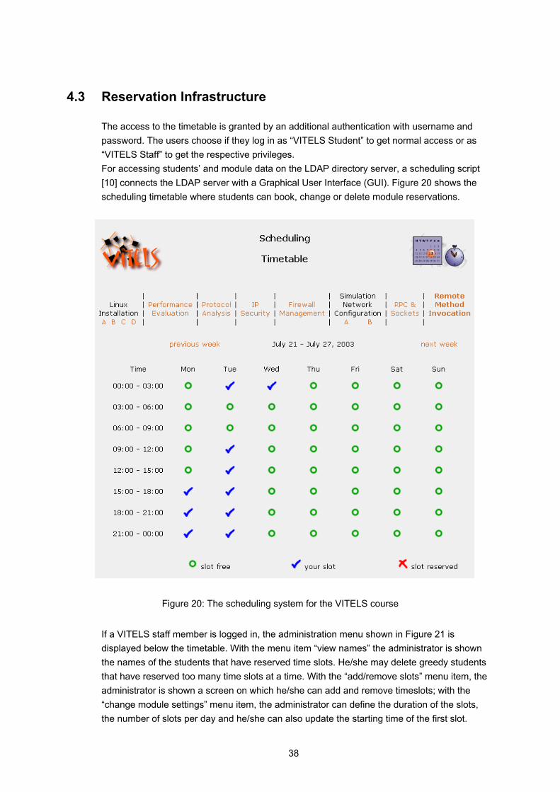
The access to the timetable is granted by an additional authentication with username and password. The users choose if they log in as “VITELS Student” to get normal access or as “VITELS Staff” to get the respective privileges. For accessing students’ and module data on the LDAP directory server, a scheduling script [10] connects the LDAP server with a Graphical User Interface (GUI). Figure 20 shows the scheduling timetable where students can book, change or delete module reservations.
Figure 20: The scheduling system for the VITELS course
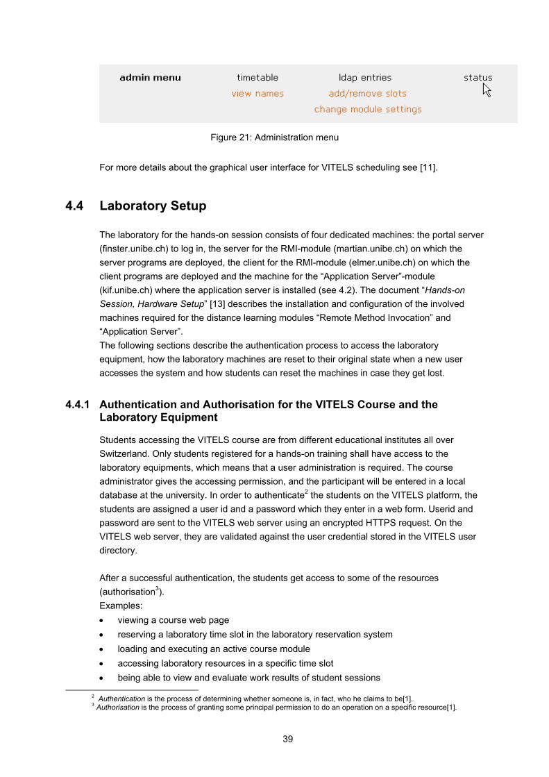
If a VITELS staff member is logged in, the administration menu shown in Figure 21 is displayed below the timetable. With the menu item “view names” the administrator is shown the names of the students that have reserved time slots. He/she may delete greedy students that have reserved too many time slots at a time. With the “add/remove slots” menu item, the administrator is shown a screen on which he/she can add and remove timeslots; with the “change module settings” menu item, the administrator can define the duration of the slots, the number of slots per day and he/she can also update the starting time of the first slot.
39
Figure 21: Administration menu
For more details about the graphical user interface for VITELS scheduling see [11].
4.4 Laboratory Setup
The laboratory for the hands-on session consists of four dedicated machines: the portal server (finster.unibe.ch) to log in, the server for the RMI-module (martian.unibe.ch) on which the server programs are deployed, the client for the RMI-module (elmer.unibe.ch) on which the client programs are deployed and the machine for the “Application Server”-module (kif.unibe.ch) where the application server is installed (see 4.2). The document “Hands-on Session, Hardware Setup” [13] describes the installation and configuration of the involved machines required for the distance learning modules “Remote Method Invocation” and “Application Server”. The following sections describe the authentication process to access the laboratory equipment, how the laboratory machines are reset to their original state when a new user accesses the system and how students can reset the machines in case they get lost.
4.4.1 Authentication and Authorisation for the VITELS Course and the Laboratory Equipment
Students accessing the VITELS course are from different educational institutes all over Switzerland. Only students registered for a hands-on training shall have access to the laboratory equipments, which means that a user administration is required. The course administrator gives the accessing permission, and the participant will be entered in a local database at the university. In order to authenticate2 the students on the VITELS platform, the students are assigned a user id and a password which they enter in a web form. Userid and password are sent to the VITELS web server using an encrypted HTTPS request. On the VITELS web server, they are validated against the user credential stored in the VITELS user directory. After a successful authentication, the students get access to some of the resources (authorisation3). Examples: • viewing a course web page • reserving a laboratory time slot in the laboratory reservation system • loading and executing an active course module • accessing laboratory resources in a specific time slot • being able to view and evaluate work results of student sessions
2 Authentication is the process of determining whether someone is, in fact, who he claims to be[1]. 3 Authorisation is the process of granting some principal permission to do an operation on a specific resource[1].
40
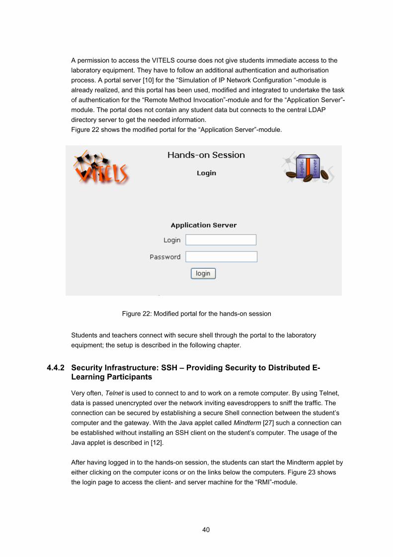
A permission to access the VITELS course does not give students immediate access to the laboratory equipment. They have to follow an additional authentication and authorisation process. A portal server [10] for the “Simulation of IP Network Configuration “-module is already realized, and this portal has been used, modified and integrated to undertake the task of authentication for the “Remote Method Invocation”-module and for the “Application Server”-module. The portal does not contain any student data but connects to the central LDAP directory server to get the needed information. Figure 22 shows the modified portal for the “Application Server”-module.
Figure 22: Modified portal for the hands-on session
Students and teachers connect with secure shell through the portal to the laboratory equipment; the setup is described in the following chapter.
4.4.2 Security Infrastructure: SSH – Providing Security to Distributed E-Learning Participants
Very often, Telnet is used to connect to and to work on a remote computer. By using Telnet, data is passed unencrypted over the network inviting eavesdroppers to sniff the traffic. The connection can be secured by establishing a secure Shell connection between the student’s computer and the gateway. With the Java applet called Mindterm [27] such a connection can be established without installing an SSH client on the student’s computer. The usage of the Java applet is described in [12]. After having logged in to the hands-on session, the students can start the Mindterm applet by either clicking on the computer icons or on the links below the computers. Figure 23 shows the login page to access the client- and server machine for the “RMI”-module.

41
Figure 23: The login page to the client- and server machine
In a first step, the Mindterm applet initializes an SSH connection from the student’s computer to the gateway. This connection will be automatically redirected to either the server or the client machine. To redirect the login from the portal server to the client and server machines new users (for example “user1”) had to be added on the portal. For each new user a new file (e.g. “user1”) must be created in the directory “/root/”. Listing 3 shows the content of one of these files. #!/bin/sh /usr/bin/ssh 10.1.1.35
Listing 3: Content of the file “/root/user1” on the gateway
Now the student has a SSH window for each machine. Figure 24 shows an SSH session with “martian.unibe.ch”.

42
Figure 24: SSH session with the “Server”
It is possible to transfer source files to the laboratory computers using the “Send ASCII File“-command from Mindterm's File menu. Since the laboratory devices are behind the university’s firewall, Mindterm's “SCP File Transfer”-command is not supported, which means that no files can be transferred from the laboratory machines to the student machine.
4.4.3 Preparing and Resetting Laboratory Equipment for a Hands-on Session
After a student has finished his/her laboratory session, the client and server machines must be reset to their original state to be ready for the next student. Every time a new student logs in to the laboratory, a script is called that resets the machines to their original state. In order to find out if the user in the current session is different from the last user, the current user’s name is compared with the last user’s name written into a file. If the user names are identical the user can log in. If not, a script is called which deletes all files in the directory “/home/rmi1” and “/home/rmi2” on “10.1.1.20” and “10.1.1.21” or “/home/apps0” on “10.1.1.35”. Then, new passwords for the users are generated and set. The new username is written into the username-file. Listing 4 shows the cleanup script for the server and the client machine for the “RMI”-module.

43
#!/bin/bash # # cleanup script for Module 9: RMI # # delete old user directories and create new user directories ssh [email protected] "rm -rf /home/rmi1;cp -a /root/rmi1/ /home" ssh [email protected] "rm -rf /home/rmi2;cp -a /root/rmi2/ /home" # create new password passwd=`openssl rand -base64 6` # change user passwords (echo $passwd;sleep 1;echo $passwd)|passwd rmi1 2>/dev/null (echo $passwd;sleep 1;echo $passwd)|passwd rmi2 2>/dev/null # change applet parameters sed /password/s!value=\"........\"!value=\"$passwd\"! [LF] /home/portal/public_html/module_9/module_9.php > temp su portal -c 'cp temp /home/portal/public_html/module_9/module_9.php' rm -f temp
Listing 4: The cleanup script for the server and for the client machine (RMI)
To run the script the command “sudo /root/cleanup.scr” is used, and the user “www-data” must get permission to access the cleanup script. The command sudo (superuser do) allows a system administrator to give certain users (or groups of users) the ability to run some (or all) commands as root or another user while logging the commands and arguments. The sudoers file is composed of two types of entries: aliases (basically variables) and user specifications (which specify who may run what) [23]. Listing 5 shows the “/etc/sudoers” – file that gives the user “www-data” permission to run the cleanup script. # This file MUST be edited with the 'visudo' command as root. # # See the man page for details on how to write a sudoers file. # # User privilege specification www-data localhost = NOPASSWD: /root/cleanup.scr www-data finster = NOPASSWD: /root/cleanup.scr www-data finster = NOPASSWD: /root/cleanup_server.scr www-data finster = NOPASSWD: /root/cleanup_client.scr
Listing 5: The sudoer file
44
4.4.4 Error Detection and Correction
One of the major disadvantages of a remote laboratory session is the fact that most of the time there is no tutor and no other students available to ask question. There is a certain danger that students may get lost or do not know how to respond to a critical system failure during the execution of the laboratory session. As part of the recovery functions, a virtual “emergency button” (Reset Button) should be provided that allows students to restart the exercise session at any time. At the bottom of the “Hands-on Session” side for the “Remote Method Invocation”-module and the “Application Server”-module, buttons are integrated. With these buttons, the students can reset a machine. Since this action will delete all files and entries students have written so far, they will be warned before the cleaning action takes place. The exercises should be supervised, and the students should get a feedback, which increases the motivation for learning. For the evaluation of the hands-on sessions, the students must copy their programmed code into the final quiz of the e-learning modules. The final quiz will be evaluated by a tutor manually, and the students can earn points.
45
5 Module 1 – Remote Method Invocation
This module deals with the programming of distributed applications, which are applications composed of cooperating programs running in multiple processes. Students will become familiar with the concept of Remote Method Invocation, an object-based programming model which allows objects in different processes to communicate with each other. The objective of this module is to enable students to develop a client/server program using Java RMI.
Logo 5: Remote Method Invocation
The following sections describe the motivation for developing this module in the VITELS project. They define the learning objectives and summarize the theory of the “Remote Method Invocation”-module. Descriptions of the examples (Fazuul and Mastermind) which are used in the hands-on session as well as implementation details are given
5.1 Motivation
“The network is the computer” – this well-known advertisement slogan used by Sun Microsystems, one of the leading IT companies, propagates that our idea of computers and how we make use of them is more and more influenced by the fact that computers are connected to networks. Computers and applications are more and more organized the same way we are used to organize our work: they are no longer just busy with computing but also with communicating, collaborating, and interacting. The module “Remote Method Invocation” explains a fundamental technology for interconnecting applications running on multiple computers. In other words, those applications are running in a remote context or a distributed environment. Application developers working with object-oriented programming languages know how to design classes, specify and implement methods on these classes, create objects as instances of these classes, and invoke methods on objects in order to execute a part of the application logic in a local context. RMI enables an application developer to use the same concepts in a remote context, for instance to create references to objects running on a remote computer and to remotely invoke a method on these objects. VITELS is designed for students who have already acquired a two years’ knowledge in computer sciences or similar branches. Their already acquired knowledge provides the basics for understanding each module's new lecture material [7]. In the “Remote Method Invocation”-module, it is assumed that students have basic knowledge of the object-oriented programming language Java. They should be able to use interfaces and understand why and how they are defined. They should also know the difference between an object reference and an object itself as well as understand the passing mechanism of objects in a single process, how to invoke an object’s method, how to define, throw and catch exceptions, and how Java handles garbage collection.

46
5.2 Goals of the Module
To implement Remote Method Invocation, several different objects and modules are required. In the theory section, the students will be studying the presented programming model for distributed applications used by RMI, the use of middleware and the different objects and modules of RMI shown in Figure 25.
Figure 25: Modules and objects in RMI [2]
• Client and remote object • Communication module, • Remote reference module and remote object table, • Proxy, • Skeleton & dispatcher • Binder (location service)
Students learn how object-oriented concepts used in a local context have to be extended and adapted to fit into a remote context. Students are able to complete a given piece of client code in such a way that the client-program finds, addresses and references objects running on remote computers. The completed client then invokes a method remotely and sends the method parameters over the network to the remote computer. Students study how to complete a server-application until they are able to write the server code in such a way that it can publish its own objects on the network and other programs can access them by using RMI. As soon as the server-code responses to the client's invocation, students know they have successfully completed the exercise.
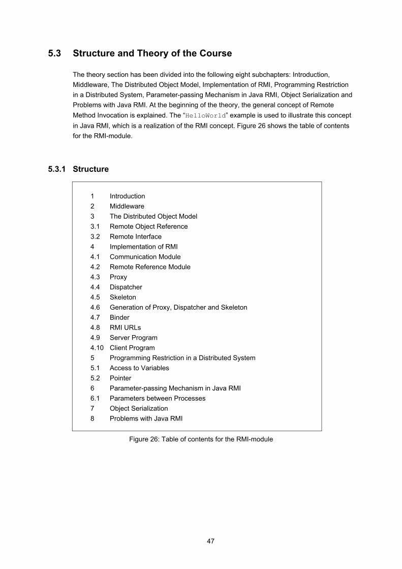
47
5.3 Structure and Theory of the Course
The theory section has been divided into the following eight subchapters: Introduction, Middleware, The Distributed Object Model, Implementation of RMI, Programming Restriction in a Distributed System, Parameter-passing Mechanism in Java RMI, Object Serialization and Problems with Java RMI. At the beginning of the theory, the general concept of Remote Method Invocation is explained. The “HelloWorld” example is used to illustrate this concept in Java RMI, which is a realization of the RMI concept. Figure 26 shows the table of contents for the RMI-module.
5.3.1 Structure
1 Introduction 2 Middleware 3 The Distributed Object Model 3.1 Remote Object Reference 3.2 Remote Interface 4 Implementation of RMI 4.1 Communication Module 4.2 Remote Reference Module 4.3 Proxy 4.4 Dispatcher 4.5 Skeleton 4.6 Generation of Proxy, Dispatcher and Skeleton 4.7 Binder 4.8 RMI URLs 4.9 Server Program 4.10 Client Program 5 Programming Restriction in a Distributed System 5.1 Access to Variables 5.2 Pointer 6 Parameter-passing Mechanism in Java RMI 6.1 Parameters between Processes 7 Object Serialization 8 Problems with Java RMI
Figure 26: Table of contents for the RMI-module
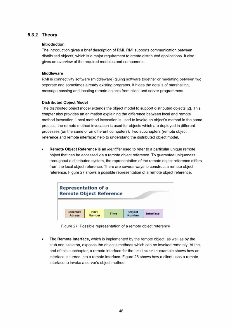
48
5.3.2 Theory
Introduction The introduction gives a brief description of RMI. RMI supports communication between distributed objects, which is a major requirement to create distributed applications. It also gives an overview of the required modules and components. Middleware RMI is connectivity software (middleware) gluing software together or mediating between two separate and sometimes already existing programs. It hides the details of marshalling, message passing and locating remote objects from client and server programmers. Distributed Object Model The distributed object model extends the object model to support distributed objects [2]. This chapter also provides an animation explaining the difference between local and remote method invocation. Local method invocation is used to invoke an object’s method in the same process; the remote method invocation is used for objects which are deployed in different processes (on the same or on different computers). Two subchapters (remote object reference and remote interface) help to understand the distributed object model. • Remote Object Reference is an identifier used to refer to a particular unique remote
object that can be accessed via a remote object reference. To guarantee uniqueness throughout a distributed system, the representation of the remote object reference differs from the local object reference. There are several ways to construct a remote object reference. Figure 27 shows a possible representation of a remote object reference.
Figure 27: Possible representation of a remote object reference
• The Remote Interface, which is implemented by the remote object, as well as by the
stub and skeleton, exposes the object’s methods which can be invoked remotely. At the end of this subchapter, a remote interface for the HelloWorld-example shows how an interface is turned into a remote interface. Figure 28 shows how a client uses a remote interface to invoke a server’s object method.
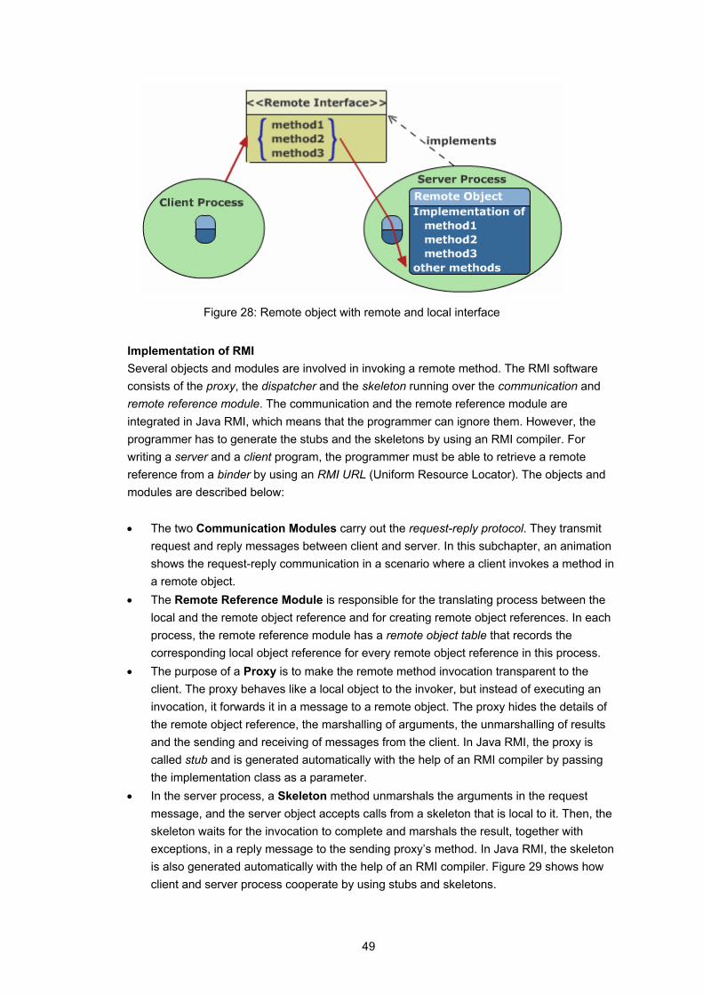
49
Figure 28: Remote object with remote and local interface
Implementation of RMI Several objects and modules are involved in invoking a remote method. The RMI software consists of the proxy, the dispatcher and the skeleton running over the communication and remote reference module. The communication and the remote reference module are integrated in Java RMI, which means that the programmer can ignore them. However, the programmer has to generate the stubs and the skeletons by using an RMI compiler. For writing a server and a client program, the programmer must be able to retrieve a remote reference from a binder by using an RMI URL (Uniform Resource Locator). The objects and modules are described below: • The two Communication Modules carry out the request-reply protocol. They transmit
request and reply messages between client and server. In this subchapter, an animation shows the request-reply communication in a scenario where a client invokes a method in a remote object.
• The Remote Reference Module is responsible for the translating process between the local and the remote object reference and for creating remote object references. In each process, the remote reference module has a remote object table that records the corresponding local object reference for every remote object reference in this process.
• The purpose of a Proxy is to make the remote method invocation transparent to the client. The proxy behaves like a local object to the invoker, but instead of executing an invocation, it forwards it in a message to a remote object. The proxy hides the details of the remote object reference, the marshalling of arguments, the unmarshalling of results and the sending and receiving of messages from the client. In Java RMI, the proxy is called stub and is generated automatically with the help of an RMI compiler by passing the implementation class as a parameter.
• In the server process, a Skeleton method unmarshals the arguments in the request message, and the server object accepts calls from a skeleton that is local to it. Then, the skeleton waits for the invocation to complete and marshals the result, together with exceptions, in a reply message to the sending proxy’s method. In Java RMI, the skeleton is also generated automatically with the help of an RMI compiler. Figure 29 shows how client and server process cooperate by using stubs and skeletons.
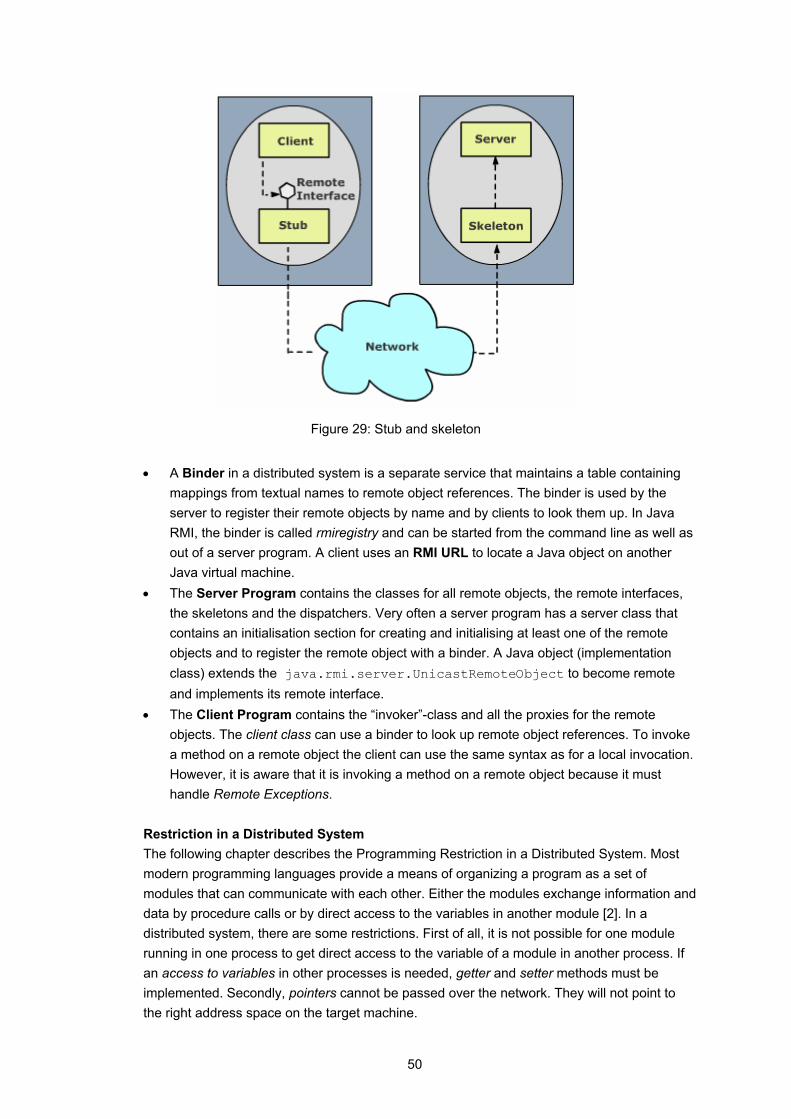
50
Figure 29: Stub and skeleton
• A Binder in a distributed system is a separate service that maintains a table containing
mappings from textual names to remote object references. The binder is used by the server to register their remote objects by name and by clients to look them up. In Java RMI, the binder is called rmiregistry and can be started from the command line as well as out of a server program. A client uses an RMI URL to locate a Java object on another Java virtual machine.
• The Server Program contains the classes for all remote objects, the remote interfaces, the skeletons and the dispatchers. Very often a server program has a server class that contains an initialisation section for creating and initialising at least one of the remote objects and to register the remote object with a binder. A Java object (implementation class) extends the java.rmi.server.UnicastRemoteObject to become remote and implements its remote interface.
• The Client Program contains the “invoker”-class and all the proxies for the remote objects. The client class can use a binder to look up remote object references. To invoke a method on a remote object the client can use the same syntax as for a local invocation. However, it is aware that it is invoking a method on a remote object because it must handle Remote Exceptions.
Restriction in a Distributed System The following chapter describes the Programming Restriction in a Distributed System. Most modern programming languages provide a means of organizing a program as a set of modules that can communicate with each other. Either the modules exchange information and data by procedure calls or by direct access to the variables in another module [2]. In a distributed system, there are some restrictions. First of all, it is not possible for one module running in one process to get direct access to the variable of a module in another process. If an access to variables in other processes is needed, getter and setter methods must be implemented. Secondly, pointers cannot be passed over the network. They will not point to the right address space on the target machine.
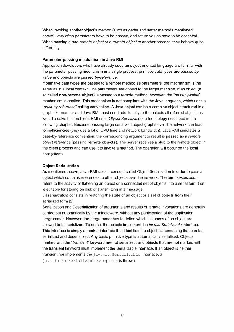
51
When invoking another object’s method (such as getter and setter methods mentioned above), very often parameters have to be passed, and return values have to be accepted. When passing a non-remote-object or a remote-object to another process, they behave quite differently. Parameter-passing mechanism in Java RMI Application developers who have already used an object-oriented language are familiar with the parameter-passing mechanism in a single process: primitive data types are passed by-value and objects are passed by-reference. If primitive data types are passed to a remote method as parameters, the mechanism is the same as in a local context: The parameters are copied to the target machine. If an object (a so called non-remote object) is passed to a remote method, however, the “pass-by-value” mechanism is applied. This mechanism is not compliant with the Java language, which uses a “pass-by-reference” calling convention. A Java object can be a complex object structured in a graph-like manner and Java RMI must send additionally to the objects all referred objects as well. To solve this problem, RMI uses Object Serialization, a technology described in the following chapter. Because passing large serialized object graphs over the network can lead to inefficiencies (they use a lot of CPU time and network bandwidth), Java RMI simulates a pass-by-reference convention: the corresponding argument or result is passed as a remote object reference (passing remote objects). The server receives a stub to the remote object in the client process and can use it to invoke a method. The operation will occur on the local host (client). Object Serialization As mentioned above, Java RMI uses a concept called Object Serialization in order to pass an object which contains references to other objects over the network. The term serialization refers to the activity of flattening an object or a connected set of objects into a serial form that is suitable for storing on disk or transmitting in a message. Deserialization consists in restoring the state of an object or a set of objects from their serialized form [2]. Serialization and Deserialization of arguments and results of remote invocations are generally carried out automatically by the middleware, without any participation of the application programmer. However, the programmer has to define which instances of an object are allowed to be serialized. To do so, the objects implement the java.io.Serializable interface. This interface is simply a marker interface that identifies the object as something that can be serialized and deserialized. Any basic primitive type is automatically serialized. Objects marked with the “transient” keyword are not serialized, and objects that are not marked with the transient keyword must implement the Serializable interface. If an object is neither transient nor implements the java.io.Serializable interface, a java.io.NotSerializableException is thrown.
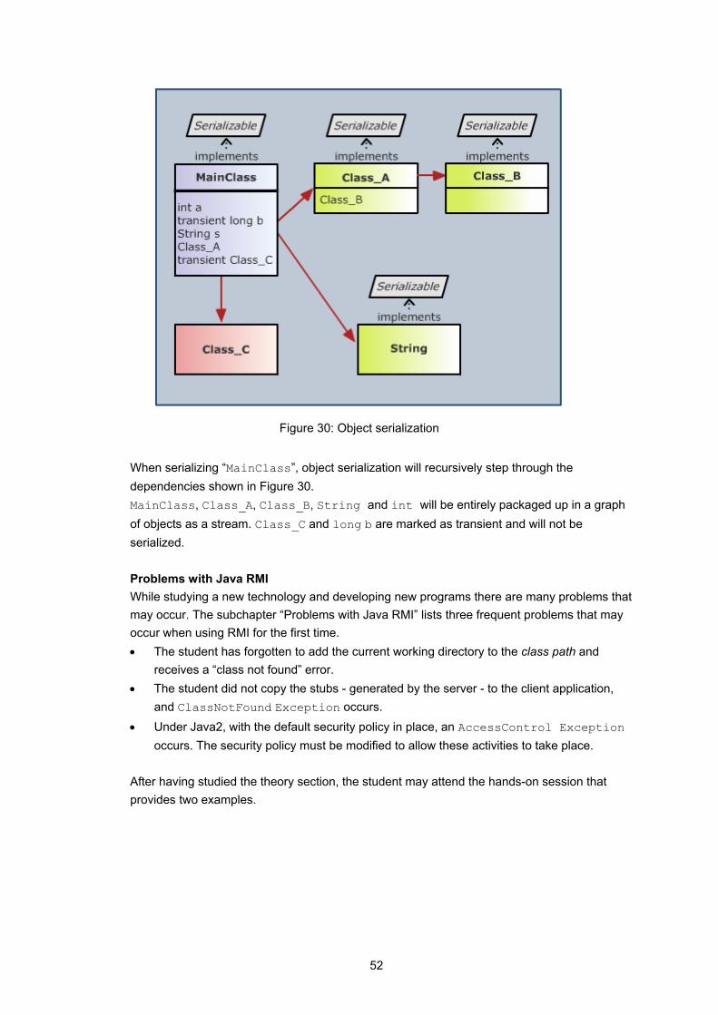
52
Figure 30: Object serialization
When serializing “MainClass”, object serialization will recursively step through the dependencies shown in Figure 30. MainClass, Class_A, Class_B, String and int will be entirely packaged up in a graph of objects as a stream. Class_C and long b are marked as transient and will not be serialized. Problems with Java RMI While studying a new technology and developing new programs there are many problems that may occur. The subchapter “Problems with Java RMI” lists three frequent problems that may occur when using RMI for the first time. • The student has forgotten to add the current working directory to the class path and
receives a “class not found” error. • The student did not copy the stubs - generated by the server - to the client application,
and ClassNotFound Exception occurs. • Under Java2, with the default security policy in place, an AccessControl Exception
occurs. The security policy must be modified to allow these activities to take place. After having studied the theory section, the student may attend the hands-on session that provides two examples.

53
5.4 Provided Examples
The goal of the hands-on session is to enable students to write their own server and client program on two single machines using Remote Method Invocation as middleware to exchange data. In the first scenario, students must complete client code for a game called “Fazuul”. In the second scenario, students complete the server program for the (well known) game “Mastermind”.
5.4.1 Fazuul – an RMI example program
The game Fazuul is used in [1] to explain the concept of stateful and stateless Enterprise Java Beans (EJB) as well as the Java 2 Platform, Enterprise Edition (J2EE). In the first hands-on scenario of the RMI e-learning module this example has been adapted. This version now uses Java RMI as middleware to connect the client program with the server program.
5.4.1.1 Description Fazuul is a simple puzzle that has an infinite amount of funny components (such as Snarf or Vrommell etc.). The objective is to put two components together to obtain another interesting component (such as Lucia). Whenever combining two components to create a new one, the old components are destroyed. But not all components fit to each other. A description of the components helps to determine the components that can be combined. The game is over as soon as the “winner” component is formed. Commands:
gimme pops out three new components
attach <component> to <component>
attaches two components to a new one and destroys the old one
inv lists the component you have
drop <component> discards a component
examine <component> gives a description of the component
suspend <filename> writes the current game state to disk
resume <filename> resumes a suspended game
quit quits the game
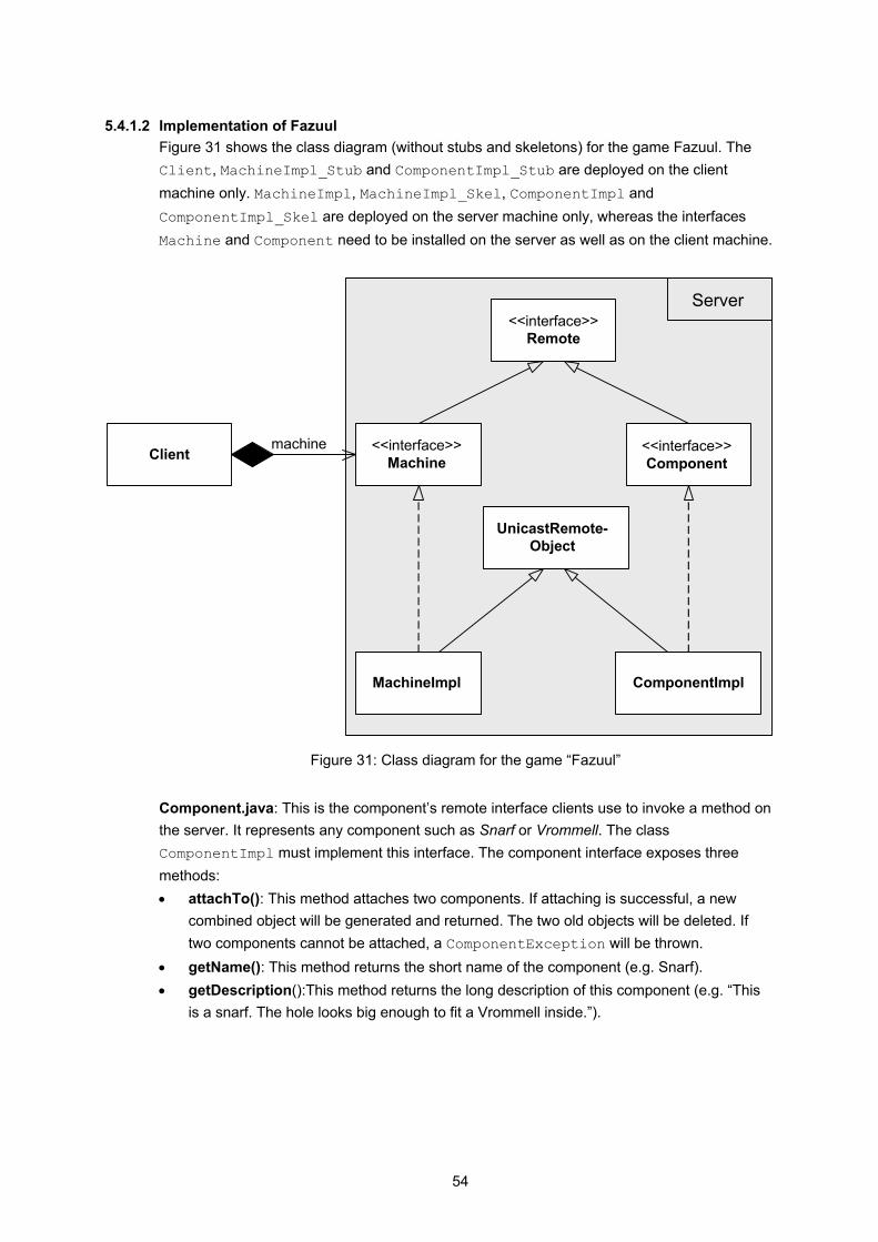
54
5.4.1.2 Implementation of Fazuul Figure 31 shows the class diagram (without stubs and skeletons) for the game Fazuul. The Client, MachineImpl_Stub and ComponentImpl_Stub are deployed on the client machine only. MachineImpl, MachineImpl_Skel, ComponentImpl and ComponentImpl_Skel are deployed on the server machine only, whereas the interfaces Machine and Component need to be installed on the server as well as on the client machine.
Client <<interface>>Machine
<<interface>>Remote
MachineImpl
machine <<interface>>Component
ComponentImpl
UnicastRemote-Object
Server
Figure 31: Class diagram for the game “Fazuul”
Component.java: This is the component’s remote interface clients use to invoke a method on the server. It represents any component such as Snarf or Vrommell. The class ComponentImpl must implement this interface. The component interface exposes three methods: • attachTo(): This method attaches two components. If attaching is successful, a new
combined object will be generated and returned. The two old objects will be deleted. If two components cannot be attached, a ComponentException will be thrown.
• getName(): This method returns the short name of the component (e.g. Snarf). • getDescription():This method returns the long description of this component (e.g. “This
is a snarf. The hole looks big enough to fit a Vrommell inside.”).

55
ComponentImpl.java: This class implements the remote interface Component and is the class that provides the programming logic. The class must extend the UnicastRemoteObject to receive the ability to be a remote object. To make the game data-driven, the component uses a property file FazuulRsc to map its short name to its long description. ComponentException.java and MachineException.java: A remote exception is thrown when there is a network problem, such as machine crashing or network dying. These classes are used to distinguish between a remote exception and an application-level exception. They delegate all calls to their super class (java.lang.Exception). Machine.java: This is the machine’s remote interface clients use to invoke a method on the server. MachineImpl must implement this interface. The Machine interface exposes one method: • makeComponent(): This method generates a new component. This can be either a
specific component, if its name is passed as a parameter, or a random component if no name is provided.
MachineImpl.java: This class implements the remote interface Machine. Like ComponentImpl, MachineImpl must also extend UnicastRemoteObject. Beside the makeComponent() method, this class also provides the main-method: the server connects to the existing registry, creates an instance of MachineImpl, makes it known to the RMI registry (under the name “Machine”) and then waits for a client to invoke a method. With the command gimme, the user gets three new basic components (a Snarf, Vrommell or Rector). The property file is used to retrieve a list with the basic components in order to check which components the machine can create. Client.java: The Client program is the invoker class and accesses the remote objects by using a stub. The client uses the RMI registry on the server machine to look up the remote object. In a simple loop, the Client waits for the user’s commands and delegates them to the server. This class also provides a text-based interface to play the game. FileLoader.java: This class is used to open and save a game state.
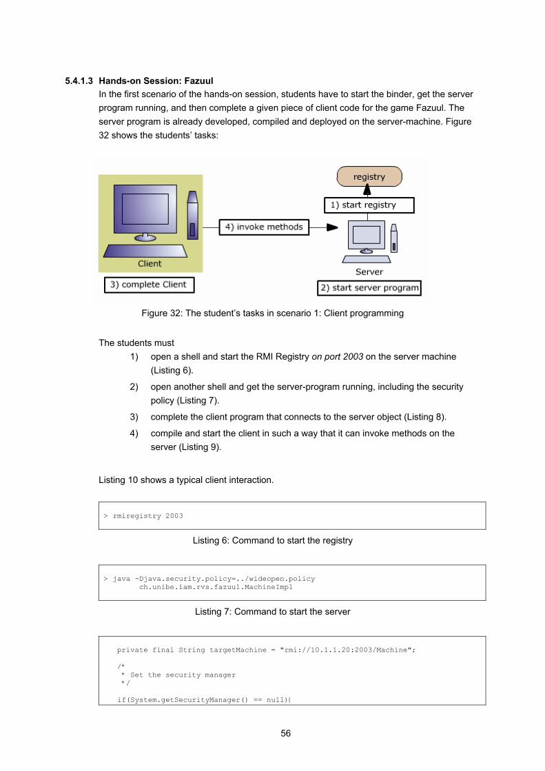
56
5.4.1.3 Hands-on Session: Fazuul In the first scenario of the hands-on session, students have to start the binder, get the server program running, and then complete a given piece of client code for the game Fazuul. The server program is already developed, compiled and deployed on the server-machine. Figure 32 shows the students’ tasks:
Figure 32: The student’s tasks in scenario 1: Client programming
The students must
1) open a shell and start the RMI Registry on port 2003 on the server machine (Listing 6).
2) open another shell and get the server-program running, including the security policy (Listing 7).
3) complete the client program that connects to the server object (Listing 8).
4) compile and start the client in such a way that it can invoke methods on the server (Listing 9).
Listing 10 shows a typical client interaction. > rmiregistry 2003
Listing 6: Command to start the registry
> java -Djava.security.policy=../wideopen.policy ch.unibe.iam.rvs.fazuul.MachineImpl
Listing 7: Command to start the server
private final String targetMachine = "rmi://10.1.1.20:2003/Machine"; /* * Set the security manager */ if(System.getSecurityManager() == null){
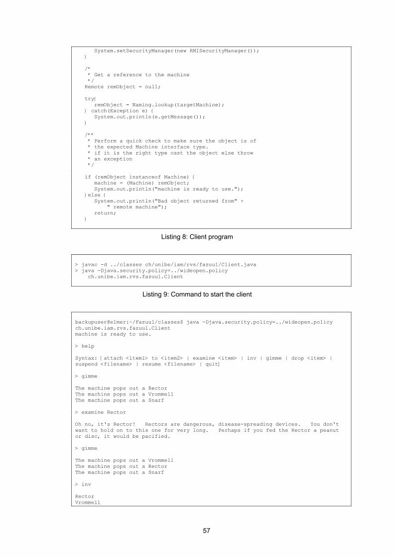
57
System.setSecurityManager(new RMISecurityManager()); } /* * Get a reference to the machine */ Remote remObject = null; try{ remObject = Naming.lookup(targetMachine); } catch(Exception e) { System.out.println(e.getMessage()); } /** * Perform a quick check to make sure the object is of * the expected Machine interface type. * if it is the right type cast the object else throw * an exception */ if (remObject instanceof Machine) { machine = (Machine) remObject; System.out.println("machine is ready to use."); }else { System.out.println("Bad object returned from" + " remote machine"); return; }
Listing 8: Client program
> javac -d ../classes ch/unibe/iam/rvs/fazuul/Client.java > java -Djava.security.policy=../wideopen.policy ch.unibe.iam.rvs.fazuul.Client
Listing 9: Command to start the client
backupuser@elmer:~/Fazuul/classes$ java -Djava.security.policy=../wideopen.policy ch.unibe.iam.rvs.fazuul.Client machine is ready to use. > help Syntax: [attach <item1> to <item2> | examine <item> | inv | gimme | drop <item> | suspend <filename> | resume <filename> | quit] > gimme The machine pops out a Rector The machine pops out a Vrommell The machine pops out a Snarf > examine Rector Oh no, it's Rector! Rectors are dangerous, disease-spreading devices. You don't want to hold on to this one for very long. Perhaps if you fed the Rector a peanut or disc, it would be pacified. > gimme The machine pops out a Vrommell The machine pops out a Rector The machine pops out a Snarf > inv Rector Vrommell
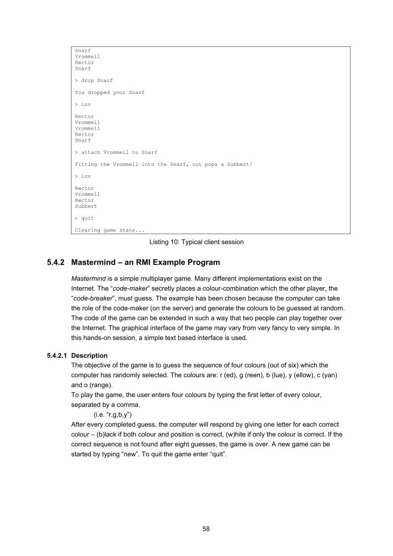
58
Snarf Vrommell Rector Snarf > drop Snarf You dropped your Snarf > inv Rector Vrommell Vrommell Rector Snarf > attach Vrommell to Snarf Fitting the Vrommell into the Snarf, out pops a Subbert! > inv Rector Vrommell Rector Subbert > quit Clearing game state...
Listing 10: Typical client session
5.4.2 Mastermind – an RMI Example Program
Mastermind is a simple multiplayer game. Many different implementations exist on the Internet. The “code-maker” secretly places a colour-combination which the other player, the “code-breaker”, must guess. The example has been chosen because the computer can take the role of the code-maker (on the server) and generate the colours to be guessed at random. The code of the game can be extended in such a way that two people can play together over the Internet. The graphical interface of the game may vary from very fancy to very simple. In this hands-on session, a simple text based interface is used.
5.4.2.1 Description The objective of the game is to guess the sequence of four colours (out of six) which the computer has randomly selected. The colours are: r (ed), g (reen), b (lue), y (ellow), c (yan) and o (range). To play the game, the user enters four colours by typing the first letter of every colour, separated by a comma.
(i.e. “r,g,b,y”) After every completed guess, the computer will respond by giving one letter for each correct colour – (b)lack if both colour and position is correct, (w)hite if only the colour is correct. If the correct sequence is not found after eight guesses, the game is over. A new game can be started by typing “new”. To quit the game enter “quit”.
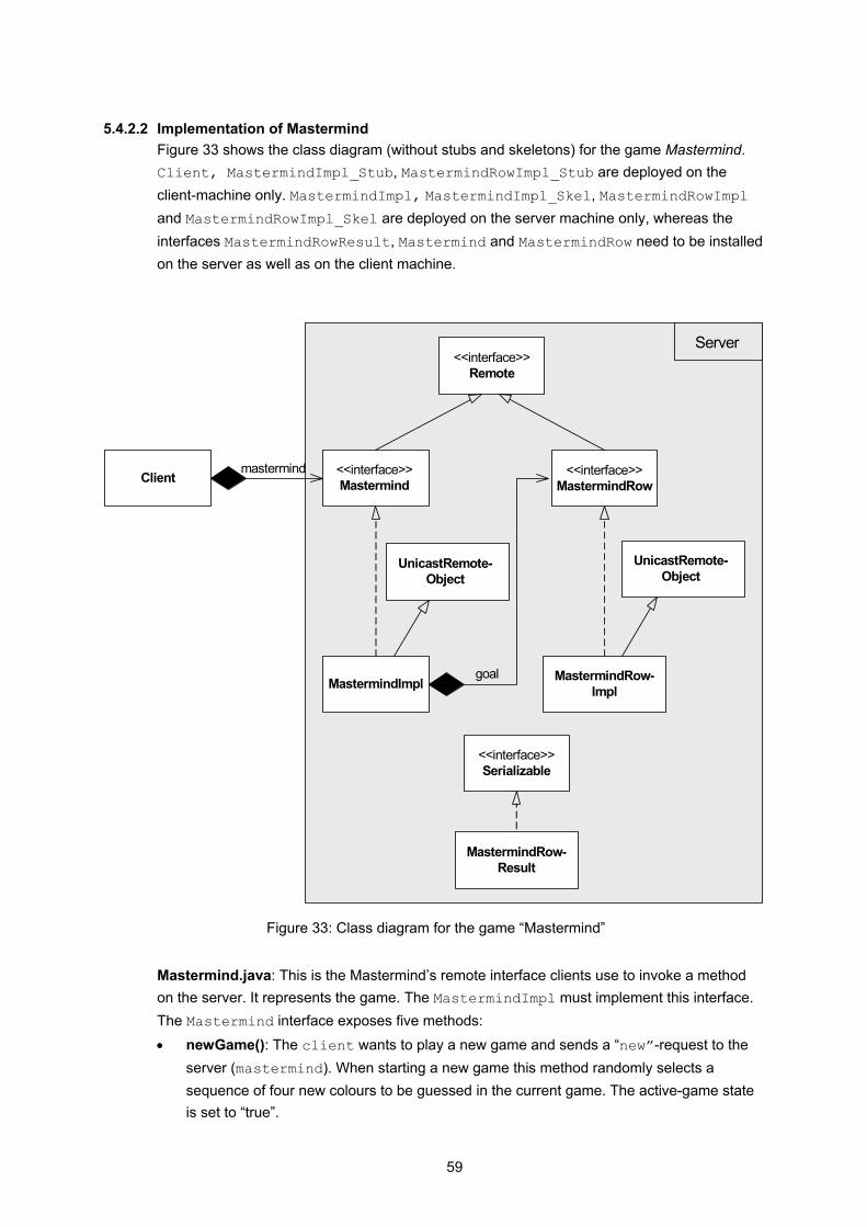
59
5.4.2.2 Implementation of Mastermind Figure 33 shows the class diagram (without stubs and skeletons) for the game Mastermind. Client, MastermindImpl_Stub, MastermindRowImpl_Stub are deployed on the client-machine only. MastermindImpl, MastermindImpl_Skel, MastermindRowImpl and MastermindRowImpl_Skel are deployed on the server machine only, whereas the interfaces MastermindRowResult, Mastermind and MastermindRow need to be installed on the server as well as on the client machine.
Client <<interface>>Mastermind
<<interface>>Remote
MastermindImpl
mastermind <<interface>>MastermindRow
MastermindRow-Impl
UnicastRemote-Object
UnicastRemote-Object
goal
<<interface>>Serializable
MastermindRow-Result
Server
Figure 33: Class diagram for the game “Mastermind”
Mastermind.java: This is the Mastermind’s remote interface clients use to invoke a method on the server. It represents the game. The MastermindImpl must implement this interface. The Mastermind interface exposes five methods: • newGame(): The client wants to play a new game and sends a “new”-request to the
server (mastermind). When starting a new game this method randomly selects a sequence of four new colours to be guessed in the current game. The active-game state is set to “true”.
60
• playRow(): If the game state is active, the player can start guessing colours which the client program wraps into the class MastermindRow. This method then checks the given colours and returns the result as MastermindRowResult: (b)lack if the colour was also in the right place, (w)hite if only the colour was correct. If no game is active, a NoGameException will be thrown.
• getGoal(): If the sequence is not found by the 8th guess, the game is over and the player is shown the correct sequence. This method returns an instance of MastermindRow that contains the colours randomly selected by the computer.
• setActiveGame(): This method sets the game state: “true” if a new game is started, “false” if the game is over.
• createRow(): This method creates a new mastermind row with the colours guessed by the player.
MastermindImpl.java: This class implements the remote interface Mastermind. It is the class that provides the programming logic. The class must extend the UnicastRemoteObject to receive the ability to be a remote object. It also provides the main-method: the server creates and connects to the registry with the port number (from the command line) as parameter, creates an instance of MastermindImpl, makes it known to the RMI registry (under the name “Mastermind”) and then waits for a client to invoke a method.
MastermindRow.java: This is the interface for the MastermindRowImpl. In order to become a remote object, the interface "MastermindRow" implements the java.rmi.Remote interface. The methods exposed in this interface are setter and getter-methods to access the private variables described below.
MastermindRowImpl.java: This class represents a row in the Mastermind game. It is used by the “code-maker” (server) to generate the colours to be guessed. Every time a client plays a new row, Mastermind creates an instance of MastermindRowImpl based on the colours guessed. The class provides two private variables: colors, where the guessed colours are saved and activeGame that saves the game state (true or false). MastermindRowResult.java: This class is used to save the result of a user’s guess (the number of black and white pegs). One possibility to pass a parameter over the network is to use a remote object. Another one is to serialize the object: the class implements the interface java.io.Serializable to flatten itself into a serial form that is suitable for being transmitted over the network. NoGameException.java: A remote exception is thrown when there is a network problem, such as machine crashing or a dying network. This class is used to distinguish a remote exception from an application-level exception. It delegates all calls to its super class (java.lang.Exception).
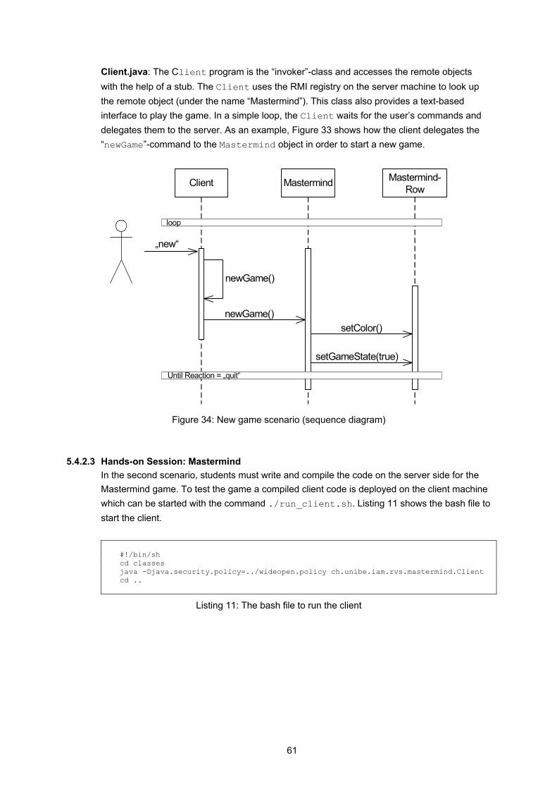
61
Client.java: The Client program is the “invoker”-class and accesses the remote objects with the help of a stub. The Client uses the RMI registry on the server machine to look up the remote object (under the name “Mastermind”). This class also provides a text-based interface to play the game. In a simple loop, the Client waits for the user’s commands and delegates them to the server. As an example, Figure 33 shows how the client delegates the “newGame”-command to the Mastermind object in order to start a new game.
„new“
newGame()
newGame()
Client Mastermind-Row
Mastermind
setColor()
setGameState(true)
loop
Until Reaction = „quit“
Figure 34: New game scenario (sequence diagram)
5.4.2.3 Hands-on Session: Mastermind In the second scenario, students must write and compile the code on the server side for the Mastermind game. To test the game a compiled client code is deployed on the client machine which can be started with the command ./run_client.sh. Listing 11 shows the bash file to start the client. #!/bin/sh cd classes java -Djava.security.policy=../wideopen.policy ch.unibe.iam.rvs.mastermind.Client cd ..
Listing 11: The bash file to run the client
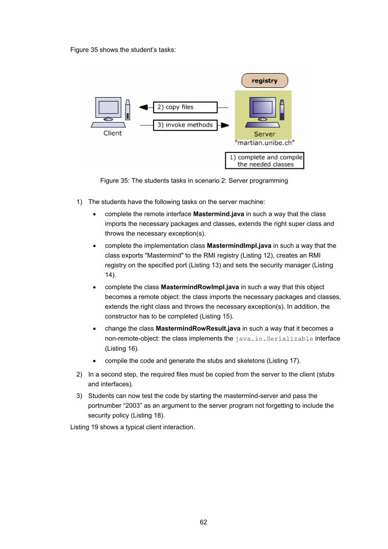
62
Figure 35 shows the student’s tasks:
Figure 35: The students tasks in scenario 2: Server programming
1) The students have the following tasks on the server machine:
• complete the remote interface Mastermind.java in such a way that the class imports the necessary packages and classes, extends the right super class and throws the necessary exception(s).
• complete the implementation class MastermindImpl.java in such a way that the class exports "Mastermind" to the RMI registry (Listing 12), creates an RMI registry on the specified port (Listing 13) and sets the security manager (Listing 14).
• complete the class MastermindRowImpl.java in such a way that this object becomes a remote object: the class imports the necessary packages and classes, extends the right class and throws the necessary exception(s). In addition, the constructor has to be completed (Listing 15).
• change the class MastermindRowResult.java in such a way that it becomes a non-remote-object: the class implements the java.io.Serializable interface (Listing 16).
• compile the code and generate the stubs and skeletons (Listing 17).
2) In a second step, the required files must be copied from the server to the client (stubs and interfaces).
3) Students can now test the code by starting the mastermind-server and pass the portnumber “2003” as an argument to the server program not forgetting to include the security policy (Listing 18).
Listing 19 shows a typical client interaction.
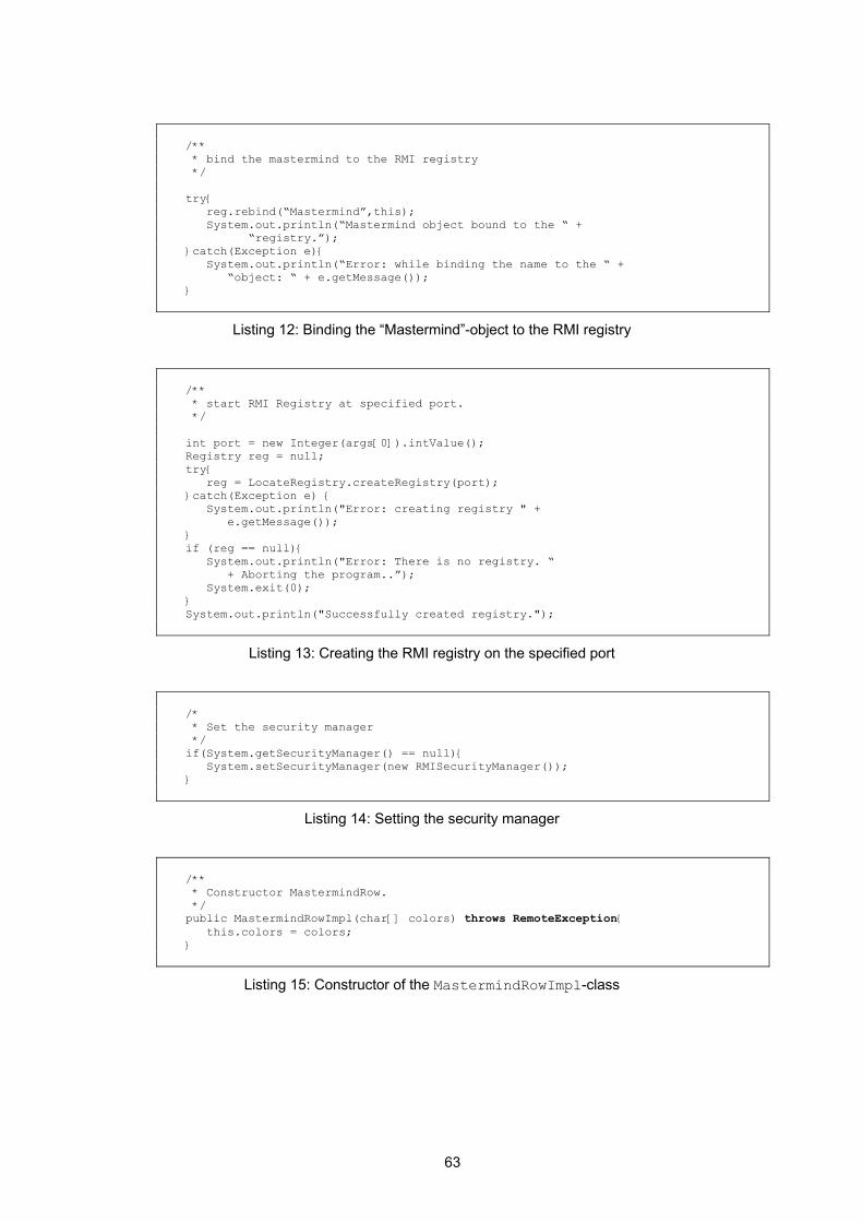
63
/** * bind the mastermind to the RMI registry */ try{ reg.rebind(“Mastermind”,this); System.out.println(“Mastermind object bound to the “ + “registry.”); }catch(Exception e){ System.out.println(“Error: while binding the name to the “ + “object: “ + e.getMessage()); }
Listing 12: Binding the “Mastermind”-object to the RMI registry
/** * start RMI Registry at specified port. */ int port = new Integer(args[0]).intValue(); Registry reg = null; try{ reg = LocateRegistry.createRegistry(port); }catch(Exception e) { System.out.println("Error: creating registry " + e.getMessage()); } if (reg == null){ System.out.println("Error: There is no registry. “ + Aborting the program..”); System.exit(0); } System.out.println("Successfully created registry.");
Listing 13: Creating the RMI registry on the specified port
/* * Set the security manager */ if(System.getSecurityManager() == null){ System.setSecurityManager(new RMISecurityManager()); }
Listing 14: Setting the security manager
/** * Constructor MastermindRow. */ public MastermindRowImpl(char[] colors) throws RemoteException{ this.colors = colors; }
Listing 15: Constructor of the MastermindRowImpl-class

64
import java.io.Serializable; /** * implement Serializable */ public class MastermindRowResult implements Serializable{ … }
Listing 16: Creation of a non-remote-object
>cd src // compiling class files >javac -d ../classes ch/unibe/iam/rvs/mastermind/*.java >cd .. >_MY_CP="/home/backupuser/Mastermind/Solution/classes" >cd classes // generating stubs and skeletons >rmic -classpath $_MY_CP ch.unibe.iam.rvs.mastermind.MastermindImpl >rmic -classpath $_MY_CP ch.unibe.iam.rvs.mastermind.MastermindRowImpl >cd ..
Listing 17: Compiling the Java classes and generating stubs and skeletons
>cd classes >java -Djava.security.policy=../wideopen.policy [LF] ch.unibe.iam.rvs.mastermind.MastermindImpl 2003 >cd ..
Listing 18: Starting the server
=========================== mastermind is ready to use. =========================== possible colors are r(ed),g(reen),b(lue),y(ellow),c(yan),o(range) Syntax: [new | x,x,x,x where x in {r,g,b,y,c,o} | quit] Start a new game with <new> 0> new 0> r,g,b,y r g b y | w w w 1> c,o,c,o c o c o | 2> g,b,y,g g b y g | b b 3> k Syntax: [new | x,x,x,x where x in {r,g,b,y,c,o} | quit] 3> g,b,r,r g b r r | b b 4> y,b,y,r y b y r | b b w 5> g,g,g,g g g g g | b 6> g,b,r,r g b r r | b b 7> g,b,r,r g b r r | b b ================= Sorry, Game over!
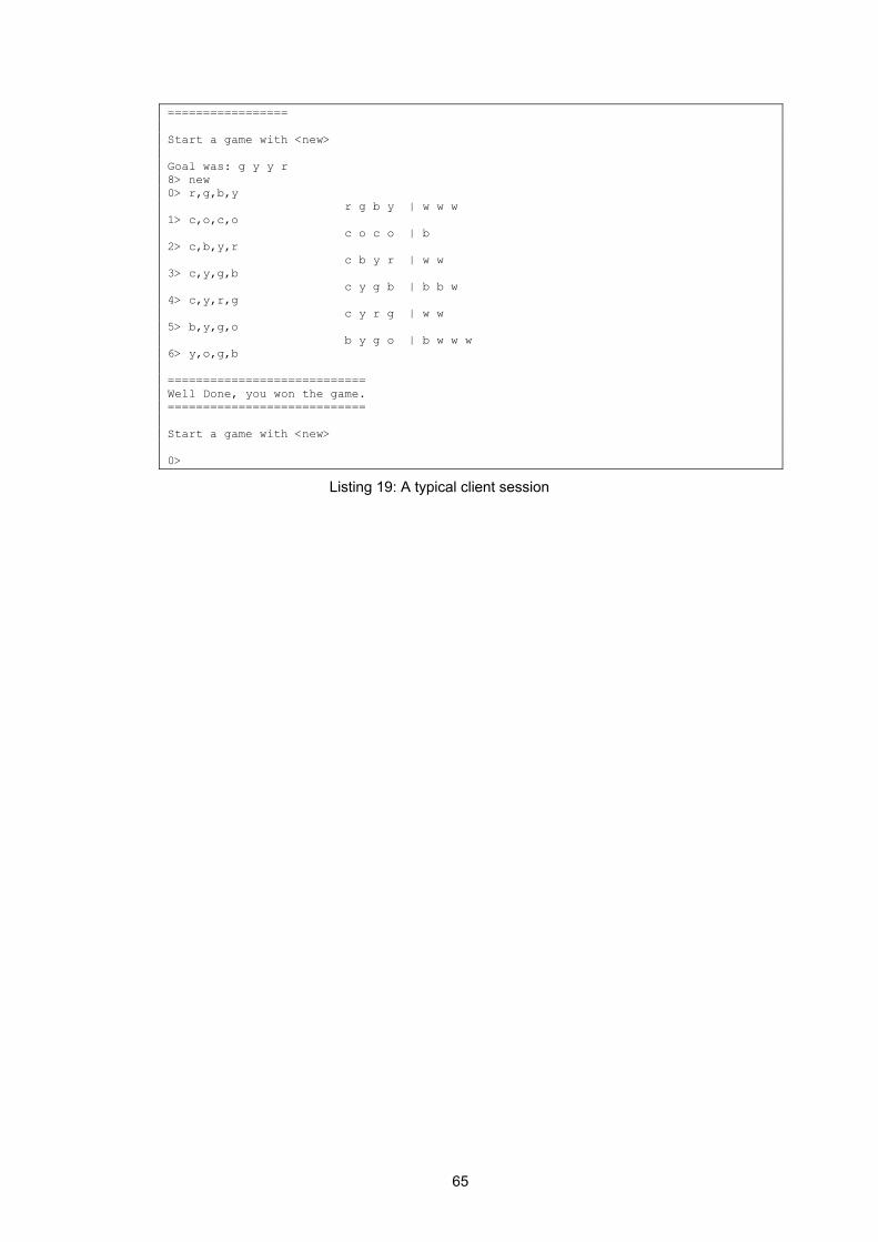
65
================= Start a game with <new> Goal was: g y y r 8> new 0> r,g,b,y r g b y | w w w 1> c,o,c,o c o c o | b 2> c,b,y,r c b y r | w w 3> c,y,g,b c y g b | b b w 4> c,y,r,g c y r g | w w 5> b,y,g,o b y g o | b w w w 6> y,o,g,b ============================ Well Done, you won the game. ============================ Start a game with <new> 0>
Listing 19: A typical client session
66
6 Module 2 – Application Server
This module provides an introduction to application servers which are an important architectural element in present-day distributed systems. In a first step, the module gives an overview of the most important concepts of an application server as well as the role application servers play in distributed systems. In a second step, it teaches how to implement, configure and deploy software components in the J2EE technology environment and, more specifically, how to use Enterprise Java Beans (EJBs) and J2EE application servers. The module also explains how recurring problems in distributed computing (e.g. naming and accessing distributed services, securing access to remote services and handling transactions) are solved in this environment.
Logo 6: Application Server
The following sections describe the motivation for developing this module in the VITELS project. They define the learning objectives and summarize the theory of the “Application Server”-module. Descriptions of the provided examples which are used in the hands-on session as well as implementation details are given.
6.1 Motivation
The architecture of modern information systems is influenced by technological progress in information technology and by the business needs information systems are designed and implemented for. These two factors are responsible for a shift in the way large information systems are designed today: • away from the monolithic server applications of the past, and toward a system
architecture which assembles a set of small, interchangeable software components into a running system.
• away from the classic separation of an information system into a client and a server part, and toward an architecture which assigns the complex task of a modern information system to software components in several architectural tiers.
This module gives an introduction to application servers, which is software to manage the complexities associated with developing distributed business systems. One of the major objectives of this software is to free the developer from programming issues like security, transactional integrity, distribution, concurrency and persistence.
67
The theoretical part also gives an introduction to Enterprise JavaBeans (EJB), i.e. software components that live within an application server. The EJB specification defines interfaces for developing server-side components with distributed technologies. One of the most important features in EJB is platform independence: “Write once, install anywhere”. This means that a component that is developed and deployed in one application server, such as an open source application server, can be moved to a different server.
6.2 Goals of the Module
The development of distributed systems with the help of an application server is quite challenging. In the theory section, students will study multi-tier architectures, the J2EE platform and, especially, the different types of Java Enterprise. By reading the theory and passing the quiz, students learn how an application server may automatically perform services such as security, transaction, persistence, naming and bean life cycle management. At the end of the module, students should understand the architecture of contemporary distributed systems. They should know how to develop, configure and deploy an EJB component and be able to access and use it from a client application.
6.3 Theory and Structure of the Course
The theory section of the Application Server”-module has been divided into eigth sub chapters, starting with an introduction to the chapter “multi tier architecture” (already explained in chapter 4.2.1). The next theory chapter gives an overview of the Java 2 Enterprise Edition (J2EE) platform and explains how the technologies bundled therein are mapped to the tiers of a modern n-tiered information system. The major part of this chapter explains how business logic can be implemented using a J2EE application server. The chapter contains a description of the J2EE application server architecture and the concept of Enterprise Java Beans (EJBs), i.e. the type of software components used in this context. It will be shown how clients can look up and access the services provided by a remote application server. The different types of EJBs are described, namely stateless session beans, stateful session beans and entity beans. A detailed description on how to describe, implement and deploy them will be provided. It will furthermore be discussed how security requirements and transaction integrity can be enforced using the respective services provided by a J2EE application server. Figure 36 shows the table of contents for the “Application Server”-module.
68
6.3.1 Structure of the Course
1 Introduction 2 Multi Tier Architecture 2.1 Two Tier Architecture 2.2 N-Tier Architecture 3 Introduction to Java 2 Platform, Enterprise Edition (J2EE) 3.1 The J2EE Technologies 3.2 The Application Server 3.3 Enterprise Java Bean 4 Architectural Overview 4.1 Object Model 4.2 Home Object, Home Interface and javax.ejb.EJBHome 4.3 EJB Object, Remote Interface and javax.ejb.EJBObject 4.4 javax.ejb.EnterpriseBean 4.5 Deployment Descriptor 4.6 Ejb-jar file and jakarta’s Ant 4.7 Client 5 Developing Beans 5.1 Session Beans 5.2 Entity Beans 5.3 The Primary Key 6 Persisting and Querying Data 6.1 Container Managed Persistence (CMP) for Entity Beans 6.2 Query Entity Beans 7 Services 7.1 Naming 7.2 Transaction 7.3 Security 8 Deployment Descriptor Reference
Figure 36: Table of contents for the “Application Server”-module
6.3.2 Introduction to Java 2 Platform, Enterprise Edition (J2EE)
J2EE is a specification suite that defines a platform for application servers. Over the past few years, several application servers which can host distributed applications have appeared on the market. In order to ensure portability, Sun has produced a complete development platform called the Java 2 Platform, Enterprise Edition (J2EE). J2EE is a collection of Java’s Enterprise APIs, integrated in a development platform that enables the programmers to develop scalable, reliable, and secure server-side applications. J2EE brings together components (EJBs, JSPs), containers (EJB container, Web Browser), and resource connectors (e.g. to a database), in one architecture. In addition, the J2EE defines how these technologies work together. Figure 37 shows some J2EE technologies.

69
Figure 37: A Java 2, Enterprise Edition (J2EE) deployment [1]
6.3.3 Architectural Overview
An application server hosts Enterprise Java Beans (EJB) which is a standard for building server-side components in Java. The first section explains an object model for a component. The second section provides an introduction to the deployment descriptor that every component must include. Finally, the last chapter provides a closer look at the components’ clients.
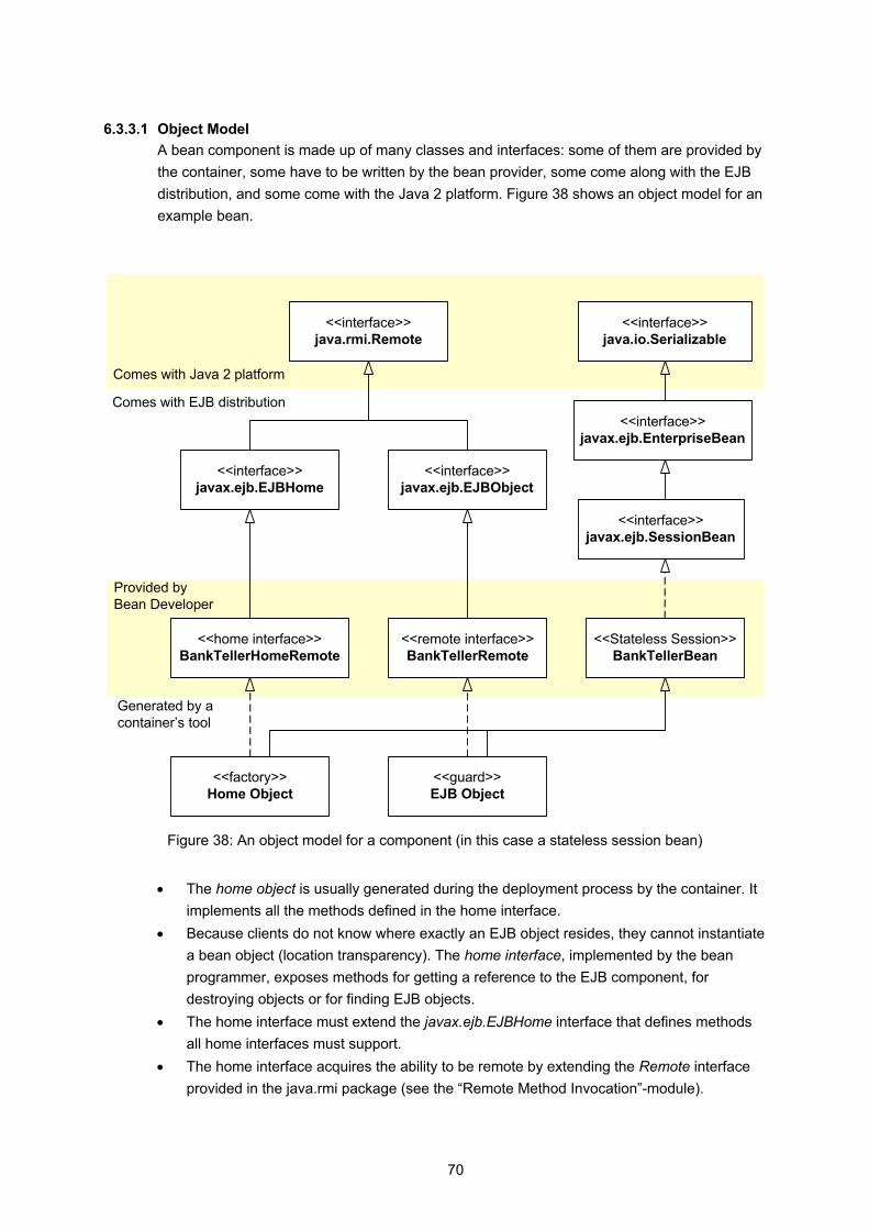
70
6.3.3.1 Object Model A bean component is made up of many classes and interfaces: some of them are provided by the container, some have to be written by the bean provider, some come along with the EJB distribution, and some come with the Java 2 platform. Figure 38 shows an object model for an example bean.
<<home interface>>BankTellerHomeRemote
<<remote interface>>BankTellerRemote
<<Stateless Session>>BankTellerBean
<<interface>>javax.ejb.EJBHome
<<interface>>javax.ejb.EJBObject
<<interface>>javax.ejb.SessionBean
<<interface>>java.rmi.Remote
<<interface>>javax.ejb.EnterpriseBean
<<factory>>Home Object
<<guard>>EJB Object
<<interface>>java.io.Serializable
Comes with Java 2 platform
Comes with EJB distribution
Provided byBean Developer
Generated by acontainer’s tool
Figure 38: An object model for a component (in this case a stateless session bean)
• The home object is usually generated during the deployment process by the container. It
implements all the methods defined in the home interface. • Because clients do not know where exactly an EJB object resides, they cannot instantiate
a bean object (location transparency). The home interface, implemented by the bean programmer, exposes methods for getting a reference to the EJB component, for destroying objects or for finding EJB objects.
• The home interface must extend the javax.ejb.EJBHome interface that defines methods all home interfaces must support.
• The home interface acquires the ability to be remote by extending the Remote interface provided in the java.rmi package (see the “Remote Method Invocation”-module).
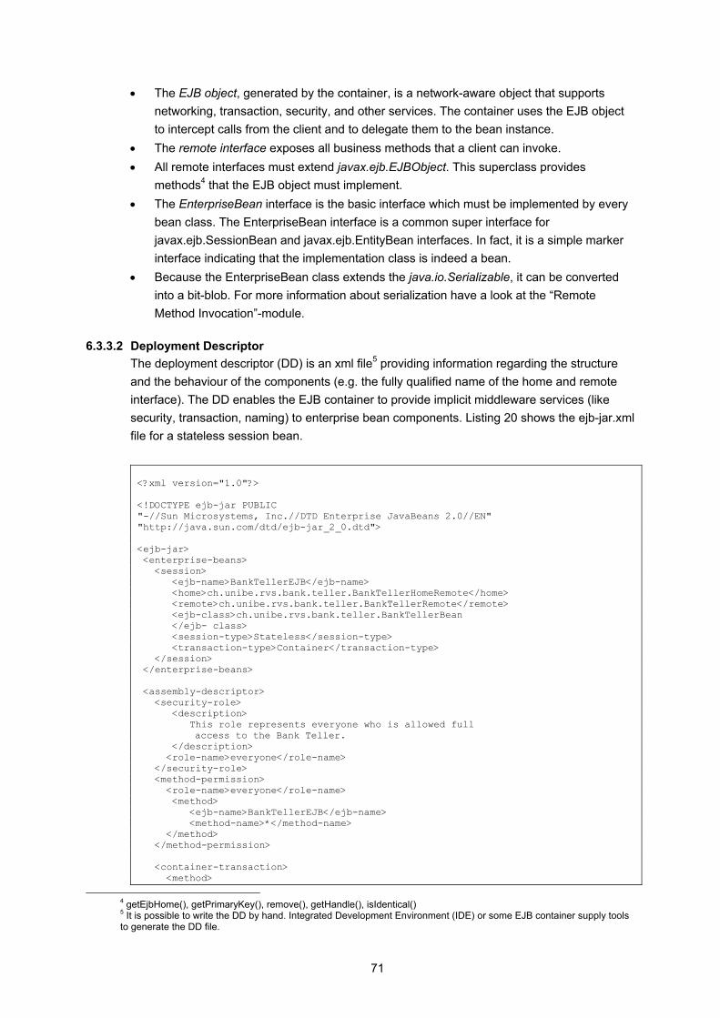
71
• The EJB object, generated by the container, is a network-aware object that supports networking, transaction, security, and other services. The container uses the EJB object to intercept calls from the client and to delegate them to the bean instance.
• The remote interface exposes all business methods that a client can invoke. • All remote interfaces must extend javax.ejb.EJBObject. This superclass provides
methods4 that the EJB object must implement. • The EnterpriseBean interface is the basic interface which must be implemented by every
bean class. The EnterpriseBean interface is a common super interface for javax.ejb.SessionBean and javax.ejb.EntityBean interfaces. In fact, it is a simple marker interface indicating that the implementation class is indeed a bean.
• Because the EnterpriseBean class extends the java.io.Serializable, it can be converted into a bit-blob. For more information about serialization have a look at the “Remote Method Invocation”-module.
6.3.3.2 Deployment Descriptor The deployment descriptor (DD) is an xml file5 providing information regarding the structure and the behaviour of the components (e.g. the fully qualified name of the home and remote interface). The DD enables the EJB container to provide implicit middleware services (like security, transaction, naming) to enterprise bean components. Listing 20 shows the ejb-jar.xml file for a stateless session bean. <?xml version="1.0"?> <!DOCTYPE ejb-jar PUBLIC "-//Sun Microsystems, Inc.//DTD Enterprise JavaBeans 2.0//EN" "http://java.sun.com/dtd/ejb-jar_2_0.dtd"> <ejb-jar> <enterprise-beans> <session> <ejb-name>BankTellerEJB</ejb-name> <home>ch.unibe.rvs.bank.teller.BankTellerHomeRemote</home> <remote>ch.unibe.rvs.bank.teller.BankTellerRemote</remote> <ejb-class>ch.unibe.rvs.bank.teller.BankTellerBean </ejb- class> <session-type>Stateless</session-type> <transaction-type>Container</transaction-type> </session> </enterprise-beans> <assembly-descriptor> <security-role> <description> This role represents everyone who is allowed full
access to the Bank Teller. </description> <role-name>everyone</role-name> </security-role> <method-permission> <role-name>everyone</role-name> <method> <ejb-name>BankTellerEJB</ejb-name> <method-name>*</method-name> </method> </method-permission> <container-transaction> <method>
4 getEjbHome(), getPrimaryKey(), remove(), getHandle(), isIdentical() 5 It is possible to write the DD by hand. Integrated Development Environment (IDE) or some EJB container supply tools to generate the DD file.
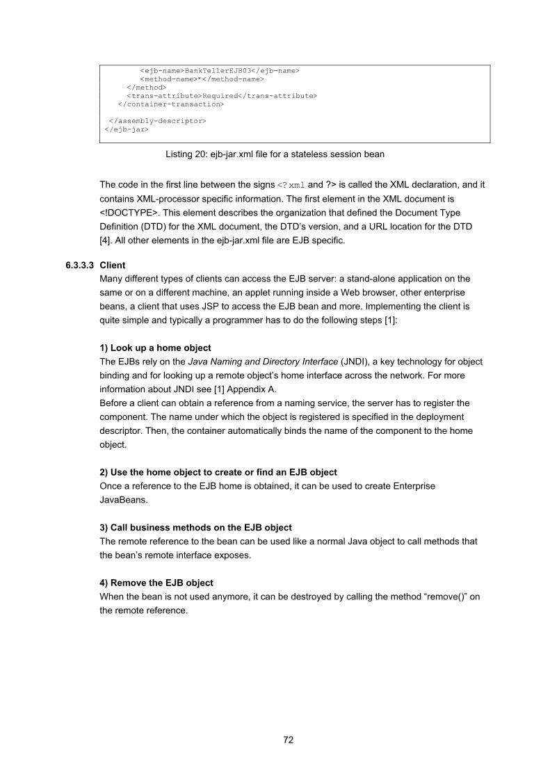
72
<ejb-name>BankTellerEJB03</ejb-name> <method-name>*</method-name> </method> <trans-attribute>Required</trans-attribute> </container-transaction> </assembly-descriptor> </ejb-jar>
Listing 20: ejb-jar.xml file for a stateless session bean
The code in the first line between the signs <?xml and ?> is called the XML declaration, and it contains XML-processor specific information. The first element in the XML document is <!DOCTYPE>. This element describes the organization that defined the Document Type Definition (DTD) for the XML document, the DTD’s version, and a URL location for the DTD [4]. All other elements in the ejb-jar.xml file are EJB specific.
6.3.3.3 Client Many different types of clients can access the EJB server: a stand-alone application on the same or on a different machine, an applet running inside a Web browser, other enterprise beans, a client that uses JSP to access the EJB bean and more. Implementing the client is quite simple and typically a programmer has to do the following steps [1]: 1) Look up a home object The EJBs rely on the Java Naming and Directory Interface (JNDI), a key technology for object binding and for looking up a remote object’s home interface across the network. For more information about JNDI see [1] Appendix A. Before a client can obtain a reference from a naming service, the server has to register the component. The name under which the object is registered is specified in the deployment descriptor. Then, the container automatically binds the name of the component to the home object. 2) Use the home object to create or find an EJB object Once a reference to the EJB home is obtained, it can be used to create Enterprise JavaBeans. 3) Call business methods on the EJB object The remote reference to the bean can be used like a normal Java object to call methods that the bean’s remote interface exposes. 4) Remove the EJB object When the bean is not used anymore, it can be destroyed by calling the method “remove()” on the remote reference.

73
UML Diagram Figure 39 shows the UML sequence diagram for the above mentioned steps.
Client EJBHome
EJBImplementation
JNDIService
lookup()
reference tohome object
create() or find()
referenceto bean
business methods
return value
Figure 39: UML sequence diagram for accessing a bean
6.3.4 Developing Beans
An enterprise bean is a server-side software component that can be deployed in a distributed environment. Currently, three types of server-side components exist: session beans, entity beans, and message driven beans. Message driven beans are not covered by this module. The next chapter explains the primary key which is used to identify an entity bean. All bean types have to implement the management call back methods. The following sections explain these methods. Management Callback Methods As mentioned earlier, the components have to implement management callback methods, as the container calls these methods to interact with the bean. At runtime, the container invokes the callback methods on the bean instance when appropriate life-cycle events occur. Every bean type has its own life-cycle. Therefore, session beans, entity beans and message driven beans do not need to implement the same methods.
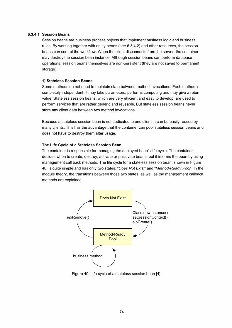
74
6.3.4.1 Session Beans Session beans are business process objects that implement business logic and business rules. By working together with entity beans (see 6.3.4.2) and other resources, the session beans can control the workflow. When the client disconnects from the server, the container may destroy the session bean instance. Although session beans can perform database operations, session beans themselves are non-persistent (they are not saved to permanent storage). 1) Stateless Session Beans Some methods do not need to maintain state between method invocations. Each method is completely independent: it may take parameters, performs computing and may give a return value. Stateless session beans, which are very efficient and easy to develop, are used to perform services that are rather generic and reusable. But stateless session beans never store any client data between two method invocations. Because a stateless session bean is not dedicated to one client, it can be easily reused by many clients. This has the advantage that the container can pool stateless session beans and does not have to destroy them after usage. The Life Cycle of a Stateless Session Bean The container is responsible for managing the deployed bean’s life cycle. The container decides when to create, destroy, activate or passivate beans, but it informs the bean by using management call back methods. The life cycle for a stateless session bean, shown in Figure 40, is quite simple and has only two states: “Does Not Exist” and “Method-Ready Pool”. In the module theory, the transitions between those two states, as well as the management callback methods are explained.
Does Not Exist
Method-ReadyPool
ejbRemove()Class.newInstance()setSessionContext()ejbCreate()
business method
Figure 40: Life cycle of a stateless session bean [4]
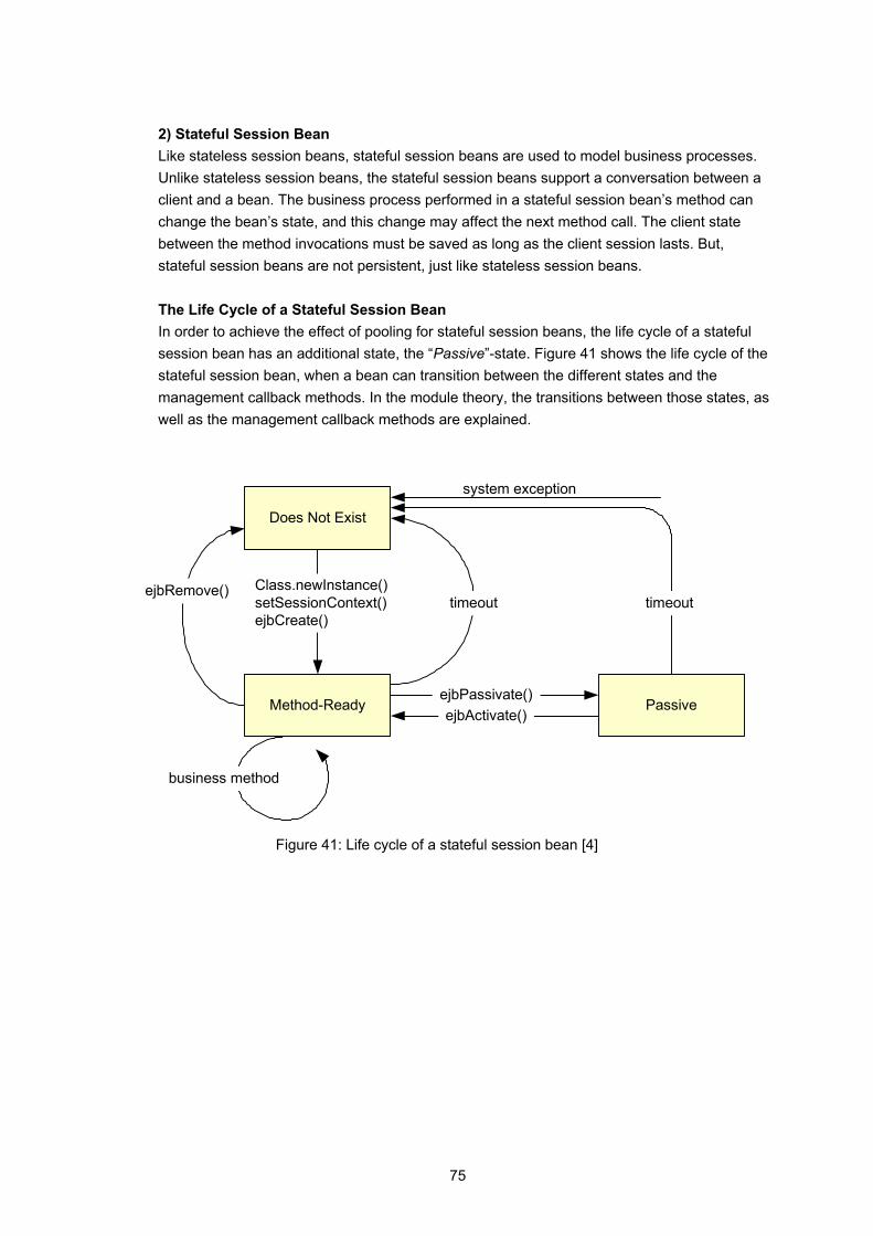
75
2) Stateful Session Bean Like stateless session beans, stateful session beans are used to model business processes. Unlike stateless session beans, the stateful session beans support a conversation between a client and a bean. The business process performed in a stateful session bean’s method can change the bean’s state, and this change may affect the next method call. The client state between the method invocations must be saved as long as the client session lasts. But, stateful session beans are not persistent, just like stateless session beans. The Life Cycle of a Stateful Session Bean In order to achieve the effect of pooling for stateful session beans, the life cycle of a stateful session bean has an additional state, the “Passive”-state. Figure 41 shows the life cycle of the stateful session bean, when a bean can transition between the different states and the management callback methods. In the module theory, the transitions between those states, as well as the management callback methods are explained.
Does Not Exist
Method-Ready
ejbRemove() Class.newInstance()setSessionContext()ejbCreate()
business method
PassiveejbPassivate()ejbActivate()
timeout timeout
system exception
Figure 41: Life cycle of a stateful session bean [4]

76
6.3.4.2 Entity Beans Session beans live about as long as a client session last. In reality, some beans exist for months or years, and therefore, there has to be a way to store the bean's data. This is what entity beans are used for: They perfectly model the behaviour and the data of business objects and they contain core business data. Session beans perform complex business logic and workflow processes (e. g. closing a bank account). In such processes, the entity bean is the object, for example the customer or the bank account. The main asset of entity beans is that they are persistent objects which know how to store themselves permanently. To put themselves into permanent storage, they use persistence mechanisms such as serialization, object-relational mapping to relational database (O/R mapping) or an object database. The Life Cycle of an Entity Bean The life cycle of an entity bean starts with its instantiation and ends when it is garbage collected. The entity bean has the most complicated life cycle of all beans. The states are: "Does Not Exist", "Pooled" and "Ready". Figure 42 shows the life cycle of an entity bean. In the module theory, the transitioning between those states, as well as the management callback methods are explained.
Does Not Exist
Ready
Class.newInstance()setEntityContext()
businessmethod
Pooled
ejbActivate()
Object.finalize()unsetEntityContext()
ejbRemove()ejbPassivate() ejbCreate()ejbPostCreate()
ejbLoad()ejbStore()ejbSelect()
ejbHome<METHOD>()ejbSelect<SUFFIX>()ejbFind<SUFFIX>()
Figure 42: Life cycle of an entity bean [4]

77
An entity bean component is made up of several files: The entity bean class is an abstract class that models persistent data and can expose simple methods to manipulate or access data. It must fill in some standard callback methods. The container will use this abstract class for generating a persistence entity class. The remote interface exposes the methods that can be invoked by a client application. This concept is the same as with session beans. The remote home interface specifies how an entity bean can be created, located or destroyed by remote clients. The home interface for an entity bean defines three basic kinds of methods: Zero or more create()-methods, one or more finder methods and zero ore more select methods. Environment properties are used in the same manner as for session beans. Entity bean’s deployment descriptor. Many of the entity bean’s elements are similar to the elements of a session bean, but there are some new deployment descriptor entries that are particular to entity beans. Entity Bean’s Primary Key Class is a unique identifier of the entity bean class and helps locating data that describes a unique record or entity in the database
6.3.4.3 The Primary Key A primary key is an object that identifies an entity bean. A client can retrieve a bean’s primary key by calling getPrimaryKey() on the remote or local interface. EJB allows two types of primary keys: Single field primary key: Very often, primitive wrapper classes (such as Integer or the class String) are used as primary key class. They are called single field primary keys because they map to exactly one of the bean’s persistence fields. Compound primary key: It is possible to use custom-made classes as primary key classes defined by a bean provider. Compound primary key classes contain one or more public fields that map to persistence fields in the bean implementation class. Sometimes, it is not possible to declare the primary key type at development time. For this case, undefined primary keys are used to defer the definition of the primary key type to the “deployer “.

78
6.3.5 Persisting and Querying Data
Two subtypes of entity beans exist: Container Managed Persistence (CMP) and Bean Managed Persistence (BMP). For CMP, the data is stored in a database by the container; the bean provider does not have to take care about the storage. With BMP, the bean provider is responsible for the data storage. This means that the bean provider must write the corresponding SQL statements. Only CMP is covered in this module. The next subchapter “Query Entity Beans” explains how existing beans can be found.
6.3.5.1 Container Managed Persistence (CMP) for Entity Beans With CMP, the container handles the persistence of entity beans. The container knows how a bean’s instance and relationship fields map to the database fields and automatically takes care of inserting, updating and deleting the data associated with entities in the database [4]. This has the advantage that the bean providers do not have to write any code to manipulate the database. Virtual Fields In CMP 2.0, the attributes of an entity bean are declares with a set of abstract accessor methods (Virtual Fields). The container will store those fields in the database. Basically, a virtual field is declared by defining an abstract get and an abstract set method in the implementation class. Because the container will perform persistence, the bean providers do not have to hard-code any persistence logic into the beans. To inform the container which fields it should manipulate, the deployment descriptor contains a description of the virtual fields. Two types of virtual fields exist: • Virtual Persistence Fields: Persistence fields can be Java serializable types (e.g.
java.lang.String) and Java primitive types (e.g. boolean). The implementation of the methods is generated at deployment time by the container. The attributes are set by calling the set()-methods (e.g. setId()) and the value of the fields can be retrieved by calling the get()-methods (i.g. getId()). The local or remote interface of the bean implementation can expose the getter and setter methods defined in the implementation class (Listing 21).
• Virtual Relationship Fields: Entity beans can form relationships with other entity beans. The relationship fields are declared by a pairs of abstract accessor methods, in the same way persistence fields are declared.
Listing 21 shows the virtual field "id". For virtual fields there is no declaration of an instance variable. /* * abstract accessor methods (persistence field) * ============================================== */ public abstract Integer getId(); public abstract void setId(Integer id);
Listing 21: Virtual fields declared in the implementation class
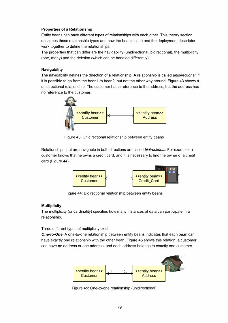
79
Properties of a Relationship Entity beans can have different types of relationships with each other. This theory section describes those relationship types and how the bean’s code and the deployment descriptor work together to define the relationships. The properties that can differ are the navigability (unidirectional, bidirectional), the multiplicity (one, many) and the deletion (which can be handled differently). Navigability The navigability defines the direction of a relationship. A relationship is called unidirectional, if it is possible to go from the bean1 to bean2, but not the other way around. Figure 43 shows a unidirectional relationship: The customer has a reference to the address, but the address has no reference to the customer.
<<entity bean>>Customer
<<entity bean>>Addressx
Figure 43: Unidirectional relationship between entity beans
Relationships that are navigable in both directions are called bidirectional. For example, a customer knows that he owns a credit card, and it is necessary to find the owner of a credit card (Figure 44).
<<entity bean>>Customer
<<entity bean>>Credit_Card
Figure 44: Bidirectional relationship between entity beans
Multiplicity The multiplicity (or cardinality) specifies how many instances of data can participate in a relationship. Three different types of multiplicity exist: One-to-One: A one-to-one relationship between entity beans indicates that each bean can have exactly one relationship with the other bean. Figure 45 shows this relation: a customer can have no address or one address, and each address belongs to exactly one customer.
<<entity bean>>Customer
<<entity bean>>Address
0..11x
Figure 45: One-to-one relationship (unidirectional)
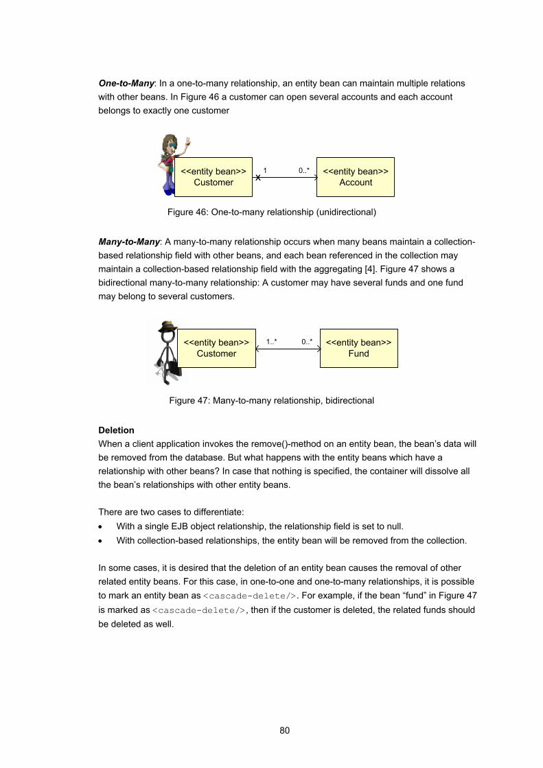
80
One-to-Many: In a one-to-many relationship, an entity bean can maintain multiple relations with other beans. In Figure 46 a customer can open several accounts and each account belongs to exactly one customer
<<entity bean>>Customer
<<entity bean>>Account
1 0..*x
Figure 46: One-to-many relationship (unidirectional)
Many-to-Many: A many-to-many relationship occurs when many beans maintain a collection-based relationship field with other beans, and each bean referenced in the collection may maintain a collection-based relationship field with the aggregating [4]. Figure 47 shows a bidirectional many-to-many relationship: A customer may have several funds and one fund may belong to several customers.
<<entity bean>>Customer
<<entity bean>>Fund
1..* 0..*
Figure 47: Many-to-many relationship, bidirectional
Deletion When a client application invokes the remove()-method on an entity bean, the bean’s data will be removed from the database. But what happens with the entity beans which have a relationship with other beans? In case that nothing is specified, the container will dissolve all the bean’s relationships with other entity beans. There are two cases to differentiate: • With a single EJB object relationship, the relationship field is set to null. • With collection-based relationships, the entity bean will be removed from the collection. In some cases, it is desired that the deletion of an entity bean causes the removal of other related entity beans. For this case, in one-to-one and one-to-many relationships, it is possible to mark an entity bean as <cascade-delete/>. For example, if the bean “fund” in Figure 47 is marked as <cascade-delete/>, then if the customer is deleted, the related funds should be deleted as well.
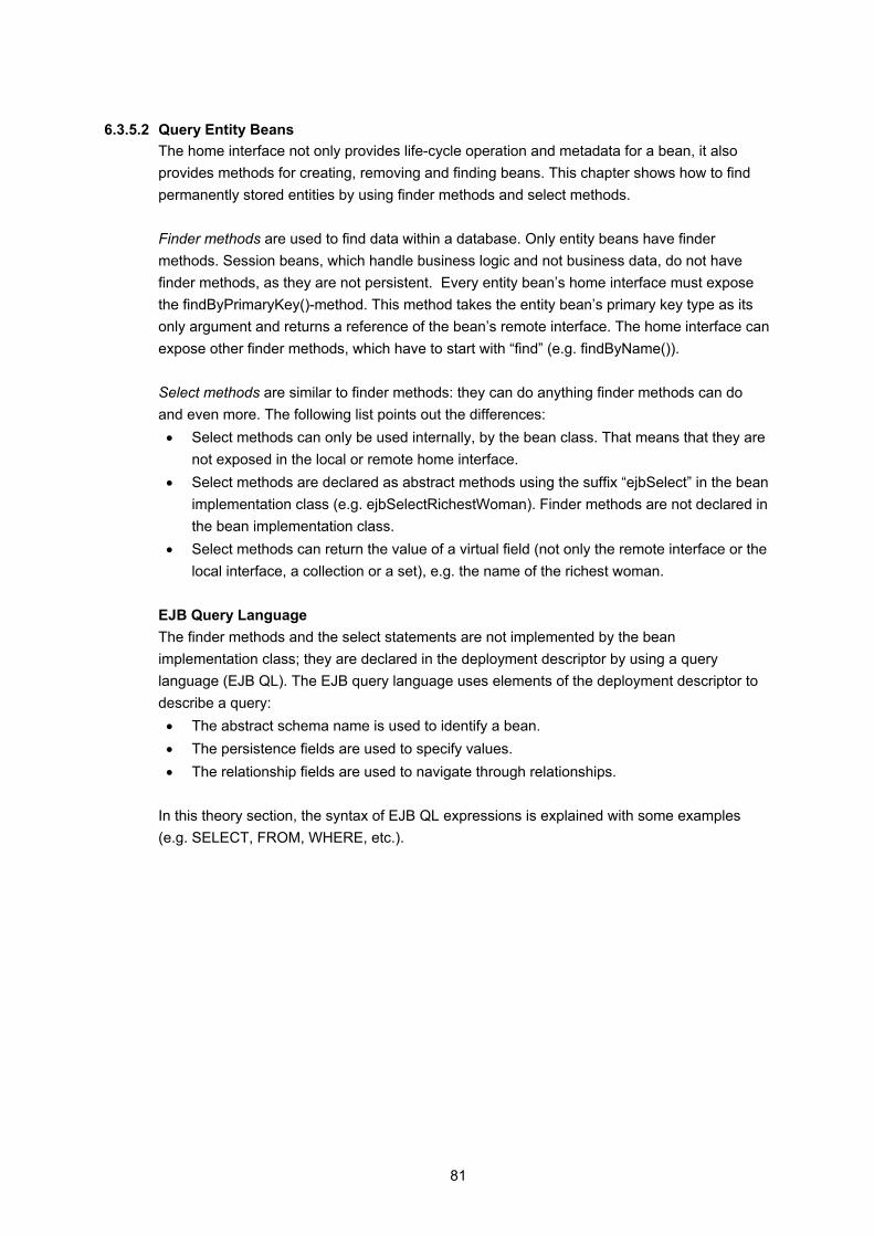
81
6.3.5.2 Query Entity Beans The home interface not only provides life-cycle operation and metadata for a bean, it also provides methods for creating, removing and finding beans. This chapter shows how to find permanently stored entities by using finder methods and select methods. Finder methods are used to find data within a database. Only entity beans have finder methods. Session beans, which handle business logic and not business data, do not have finder methods, as they are not persistent. Every entity bean’s home interface must expose the findByPrimaryKey()-method. This method takes the entity bean’s primary key type as its only argument and returns a reference of the bean’s remote interface. The home interface can expose other finder methods, which have to start with “find” (e.g. findByName()). Select methods are similar to finder methods: they can do anything finder methods can do and even more. The following list points out the differences: • Select methods can only be used internally, by the bean class. That means that they are
not exposed in the local or remote home interface. • Select methods are declared as abstract methods using the suffix “ejbSelect” in the bean
implementation class (e.g. ejbSelectRichestWoman). Finder methods are not declared in the bean implementation class.
• Select methods can return the value of a virtual field (not only the remote interface or the local interface, a collection or a set), e.g. the name of the richest woman.
EJB Query Language The finder methods and the select statements are not implemented by the bean implementation class; they are declared in the deployment descriptor by using a query language (EJB QL). The EJB query language uses elements of the deployment descriptor to describe a query: • The abstract schema name is used to identify a bean. • The persistence fields are used to specify values. • The relationship fields are used to navigate through relationships.
In this theory section, the syntax of EJB QL expressions is explained with some examples (e.g. SELECT, FROM, WHERE, etc.).

82
6.3.6 Services
Because an EJB server automatically manages some system-level services, the application developers that use an application server, do not have to write complicated services. The following chapters in the theory give a short introduction to three important services: Naming, transaction and security.
6.3.6.1 Naming All beans have a default JNDI context called JNDI Environment Naming Context (JNDI ENC), which is a special JNDI name space. The JNDI ENC allows enterprise beans to access 1) the home interface of other beans, 2) the resources (e.g. databases) and 3) the environment properties.
1) Obtaining a Reference to a Bean’s Home Interface When a bean is deployed, any beans it uses are mapped into the directory “java:comp/env/ejb”. A bean’s reference can be obtained by using the JNDI default context. If a bean wants to access another bean, the reference of this bean must be declared in the deployment descriptor.
2) Obtaining a Resource Connection (Database) A bean-managed, persistent entity bean must have access to a database to which it will persist itself. The bean usually obtains a resource factory from the JNDI ENC; a new context is created and a data source is looked up in the JNDI ENC. The deployment descriptor maps the JDBC DataSource to a context in the ENC.
3) Obtaining Environment Properties It is possible to declare named properties in the deployment descriptor. A bean accesses those properties by using the JNDI ENC. This way, the bean deployer can change the property values in the deployment descriptor, rather than change the program code.
6.3.6.2 Transaction A transaction is a unit of work that accesses one or more shared resources, like databases. A unit of work is a set of activities that must be completed together. Take the transfer of money as an example: Charging one account and crediting the other must be completed together – or nothing should be done. It is more difficult to handle transactions in a distributed system than in a pure client/server database system. The money transfer example may require changes on two databases which cannot communicate with each other and may have different locations. In order to maintain data consistency, a transaction manager ensures that all database operations are either committed or that all of them are rolled back. Two Phase Commit Protocol The transaction manager uses a two phase commit protocol to guarantee data integrity. An animation in the theory section illustrates the two phase commit protocol: A client manipulates two databases, and the transaction is controlled by a transaction manager.
83
Transactional EJBs Every J2EE application server has to support distributed transactions. Therefore, every server has a transaction manager and communicates with the resources using the two phase commit protocol. In J2EE, the bean providers have two possibilities to use server-side transaction: • Container Managed Transaction (CMT): The bean provider can let the container manage
the transaction. CMT is one of the most important features of the EJB component model: The container manages the complicated task of transaction. The bean provider can specify the transaction attributes in the deployment descriptor declaratively.
• Bean Managed Transaction (BMT): The bean provider can manage transaction in the bean. For most cases, CMT is powerful enough and much easier to handle than BMT. Only CMT is covered in the theory section.
6.3.6.3 Security The goal of every security system is to protect the available resources (like data in a database, data sent over the network, bandwidth, etc.) An application server can support three kinds of security: 1) Authentication, 2) Authorization and 3) Secure Communication. EJB addresses only authorization specifically, but most application servers support authentication (by using the JNDI API) and secure communication [4].
1) Authentication Authentication validates the identity of the user. For example, the access to a resource is granted by authentication with username and password. Username and password can be validated against the user credentials stored in a user directory6. Once a user has successfully passed the authentication system, he has access to the resources. Other authentication systems may be based on ID cards, swipe cards, security certificates, and other forms of identification. Many application servers realized authentication by using the JNDI API. A client uses JNDI to send the authentication information to the server.
2) Authorisation (Access Control) Authorisation ensures that users access only the resources for which they have been given permission. A manager may have permission to manipulate certain data, whereas an employee may only read the same data. EJB provides a possibility to define authorisations declaratively in the deployment descriptor. Deployment descriptors include elements that declare which logical roles are allowed to access which bean methods. Roles are mapped to real-world user groups and users when the bean is deployed. In a next step, the roles have to be assigned to EJB methods; this part of the deployment descriptor maps the roles into actions that are either allowed or forbidden.
6 In many projects, an existing user database (e.g. an LDAP directory) must be integrated. The EJB specification does not define a full interface for the manipulation of user data. But an application server must support the user and group management.

84
3) Secure Communication Communication channels between clients and servers have to be secured to prevent attacks (eavesdropping, data manipulation, etc.). One way to secure communication is to physically isolate the network. This solution is expensive and limiting. Another solution is to encrypt the data transferred between the client and server machines. Most application servers support secure communication, usually by the Secure Socket Layer (SSL). For more information about security see the module “IP Security”.
6.4 Provided examples
The goal of the hands-on session in the “Application Server”-module is to enable students to write their own components that run within an application server. The hands-on provides the bank examples discussed in the theory section for a stateless session bean, for a stateful session bean and for an entity bean. Furthermore, the two exercises are discussed: In the first exercise, students must complete a deployment descriptor. In the second exercise, they develop their own component. In the following chapters, these examples are discussed.
6.4.1 The Application Server
J2EE is a specification (not a product), specifying the rules of engagement that have to be agreed on when writing enterprise software [1]. Many vendors have implemented the J2EE specification and created a multitude of application servers: BEA’s Weblogic, IBM’s WebSphere, Oracle’s Oracle 9i, Borland’s Enterprise Server and many more. In order to demonstrate examples and to provide an environment to solve the exercises, an application server has been installed on a laboratory machine. The server is from the JBoss Group [54], as the JBoss server has many advantages: • JBoss application servers are widely spread and very popular. • JBoss is a flexible service-oriented J2EE application server. • The server is used by thousands of new java developers to learn EJB. • The JBoss Group provides a detailed documentation that is downloadable. • The JBoss server is easy to install. • JBoss is open source and can be obtained for free.
6.4.2 The Client for the Bank Examples
The client program is the invoker class: in a simple loop, the client waits for the user’s command and delegates it to the bank teller bean. The class provides a text-based user interface. The following list shows the steps that a client performs to access a remote component: • It acquires a JNDI initial context. • It looks up the home object using the initial context. • It uses the home object to create a bank teller. • It reads the next command from the standard input. • It delegates the command to the bank teller. • At the end, the client removes the bank teller.
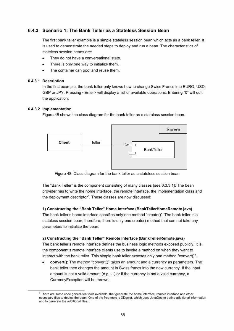
85
6.4.3 Scenario 1: The Bank Teller as a Stateless Session Bean
The first bank teller example is a simple stateless session bean which acts as a bank teller. It is used to demonstrate the needed steps to deploy and run a bean. The characteristics of stateless session beans are: • They do not have a conversational state. • There is only one way to initialize them. • The container can pool and reuse them.
6.4.3.1 Description In the first example, the bank teller only knows how to change Swiss Francs into EURO, USD, GBP or JPY. Pressing <Enter> will display a list of available operations. Entering “0” will quit the application.
6.4.3.2 Implementation Figure 48 shows the class diagram for the bank teller as a stateless session bean.
Client
BankTeller
teller
Server
Figure 48: Class diagram for the bank teller as a stateless session bean
The “Bank Teller” is the component consisting of many classes (see 6.3.3.1): The bean provider has to write the home interface, the remote interface, the implementation class and the deployment descriptor7. These classes are now discussed: 1) Constructing the “Bank Teller” Home Interface (BankTellerHomeRemote.java) The bank teller’s home interface specifies only one method “create()”. The bank teller is a stateless session bean, therefore, there is only one create()-method that can not take any parameters to initialize the bean. 2) Constructing the “Bank Teller” Remote Interface (BankTellerRemote.java) The bank teller’s remote interface defines the business logic methods exposed publicly. It is the component’s remote interface clients use to invoke a method on when they want to interact with the bank teller. This simple bank teller exposes only one method "convert()". • convert(): The method “convert()” takes an amount and a currency as parameters. The
bank teller then changes the amount in Swiss francs into the new currency. If the input amount is not a valid amount (e.g. -1) or if the currency is not a valid currency, a CurrencyException will be thrown.
7 There are some code generation tools available, that generate the home interface, remote interface and other necessary files to deploy the bean. One of the free tools is XDoclet, which uses JavaDoc to define additional information and to generate the additional files.
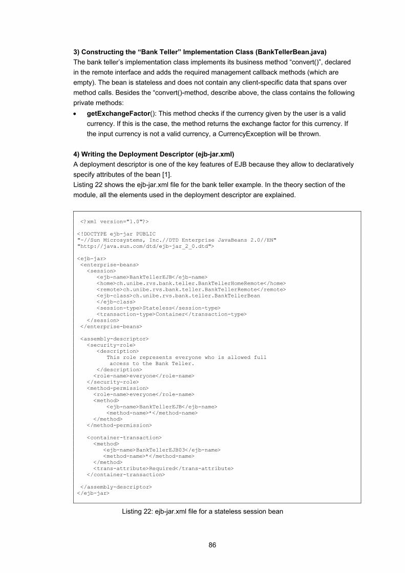
86
3) Constructing the “Bank Teller” Implementation Class (BankTellerBean.java) The bank teller’s implementation class implements its business method “convert()”, declared in the remote interface and adds the required management callback methods (which are empty). The bean is stateless and does not contain any client-specific data that spans over method calls. Besides the “convert()-method, describe above, the class contains the following private methods: • getExchangeFactor(): This method checks if the currency given by the user is a valid
currency. If this is the case, the method returns the exchange factor for this currency. If the input currency is not a valid currency, a CurrencyException will be thrown.
4) Writing the Deployment Descriptor (ejb-jar.xml) A deployment descriptor is one of the key features of EJB because they allow to declaratively specify attributes of the bean [1]. Listing 22 shows the ejb-jar.xml file for the bank teller example. In the theory section of the module, all the elements used in the deployment descriptor are explained. <?xml version="1.0"?> <!DOCTYPE ejb-jar PUBLIC "-//Sun Microsystems, Inc.//DTD Enterprise JavaBeans 2.0//EN" "http://java.sun.com/dtd/ejb-jar_2_0.dtd"> <ejb-jar> <enterprise-beans> <session> <ejb-name>BankTellerEJB</ejb-name> <home>ch.unibe.rvs.bank.teller.BankTellerHomeRemote</home> <remote>ch.unibe.rvs.bank.teller.BankTellerRemote</remote> <ejb-class>ch.unibe.rvs.bank.teller.BankTellerBean </ejb-class> <session-type>Stateless</session-type> <transaction-type>Container</transaction-type> </session> </enterprise-beans> <assembly-descriptor> <security-role> <description> This role represents everyone who is allowed full
access to the Bank Teller. </description> <role-name>everyone</role-name> </security-role> <method-permission> <role-name>everyone</role-name> <method> <ejb-name>BankTellerEJB</ejb-name> <method-name>*</method-name> </method> </method-permission> <container-transaction> <method> <ejb-name>BankTellerEJB03</ejb-name> <method-name>*</method-name> </method> <trans-attribute>Required</trans-attribute> </container-transaction> </assembly-descriptor> </ejb-jar>
Listing 22: ejb-jar.xml file for a stateless session bean
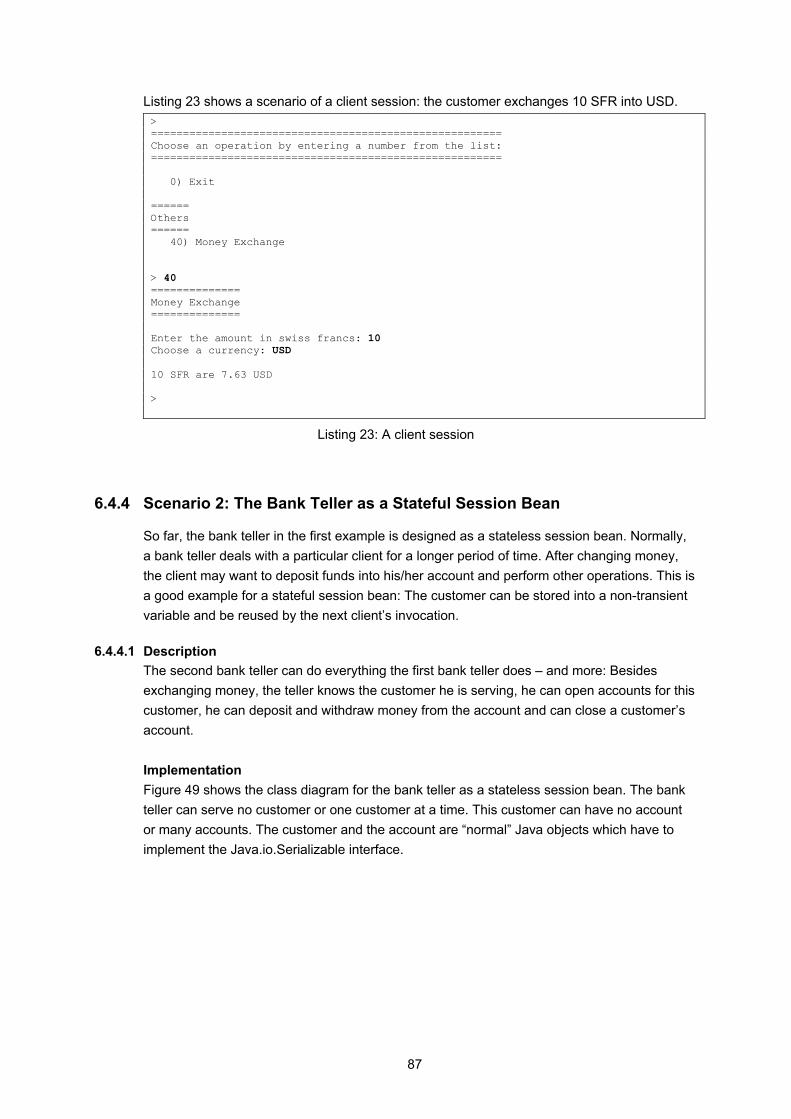
87
Listing 23 shows a scenario of a client session: the customer exchanges 10 SFR into USD. > ======================================================= Choose an operation by entering a number from the list: ======================================================= 0) Exit ====== Others ====== 40) Money Exchange > 40 ============== Money Exchange ============== Enter the amount in swiss francs: 10 Choose a currency: USD 10 SFR are 7.63 USD >
Listing 23: A client session
6.4.4 Scenario 2: The Bank Teller as a Stateful Session Bean
So far, the bank teller in the first example is designed as a stateless session bean. Normally, a bank teller deals with a particular client for a longer period of time. After changing money, the client may want to deposit funds into his/her account and perform other operations. This is a good example for a stateful session bean: The customer can be stored into a non-transient variable and be reused by the next client’s invocation.
6.4.4.1 Description The second bank teller can do everything the first bank teller does – and more: Besides exchanging money, the teller knows the customer he is serving, he can open accounts for this customer, he can deposit and withdraw money from the account and can close a customer’s account. Implementation Figure 49 shows the class diagram for the bank teller as a stateless session bean. The bank teller can serve no customer or one customer at a time. This customer can have no account or many accounts. The customer and the account are “normal” Java objects which have to implement the Java.io.Serializable interface.

88
Client<<stateful session>>
BankTeller
teller
Server
<<auxiliary>>Account
<<auxiliary>>Customer
Figure 49: Class diagram for the bank teller as a stateful session bean
There are no changes to the new bank teller’s home remote interface; it is the same interface as the stateless session bank teller uses. In this version of the bank teller, the remote interface exposes more methods. They are explained in the next section. 1) Constructing the “Bank Teller” Implementation Class (BankTellerBean.java) A stateful session bean can maintain a state and the bank teller can now store the data of the current customer. The convert()-method remains the same (as the convert()-method in the stateless session bean). • createNewCustomer() creates a new customer. If a customer exists already, it will be
discarded. The method take the customer’s first and last name as parameters and passes the name into the new customer object. Then the new customer’s id is return to the caller.
All other methods in the bank teller bean implementation take the arguments, validate the customer and delegate the method call to the customer. These methods are discussed in the customer class. 2) Constructing the “Customer” Class (Customer.java) The customer is an ordinary Java class that implements the java.io.Serializable interface, so it can be converted into a bit-blob (for passivation). The customer has four instance variables: its identification number, its first name, its last name and a vector that represents the accounts. When creating a new customer, the customer’s constructor takes the identification number to initiate the customer. The empty constructor is private: It is not allowed to create a customer without an identification number. Getter and setter methods for instance variables are not described here.
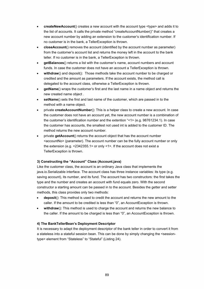
89
• createNewAccount() creates a new account with the account type <type> and adds it to the list of accounts. It calls the private method “createAccountNumber()” that creates a new account number by adding an extension to the customer’s identification number. If no customer is in the bank, a TellerException is thrown.
• closeAccount() removes the account (identified by the account number as parameter) from the customer’s account list and returns the money left in the account to the bank teller. If no customer is in the bank, a TellerException is thrown.
• getBalances() returns a list with the customer’s name, account numbers and account funds. In case the customer does not have an account a TellerException is thrown.
• withdraw() and deposit(): Those methods take the account number to be charged or credited and the amount as parameters. If the account exists, the method call is delegated to the account class, otherwise a TellerException is thrown.
• getName() wraps the customer’s first and the last name in a name object and returns the new created name object .
• setName() sets the first and last name of the customer, which are passed in to the method with a name object.
• private createAccountNumber(): This is a helper class to create a new account. In case the customer does not have an account yet, the new account number is a combination of the customer’s identification number and the extention “<1> (e.g. 98761234.1). In case the customer has accounts, the smallest not used int is added to the customer ID. The method returns the new account number.
• private getAccount() returns the account object that has the account number <accountNo> (parameter). The account number can be the fully account number or only the extension (e.g. <2342355.1> or only <1>. If the account does not exist a TellerException is thrown.
3) Constructing the “Account” Class (Account.java) Like the customer class, the account is an ordinary Java class that implements the java.io.Serializable interface. The account class has three instance variables: its type (e.g. saving account), its number, and its fund. The account has two constructors: the first takes the type and the number and creates an account with fund equals zero. With the second constructor a starting amount can be passed in to the account. Besides the getter and setter methods, this class provides only two methods: • deposit(): This method is used to credit the account and returns the new amount to the
caller. If the amount to be credited is less than “0”, an AccountException is thrown. • withdraw(): This method is used to charge the account and returns the new balance to
the caller. If the amount to be charged is less than “0”, an AccountException is thrown. 4) The BankTellerBean’s Deployment Descriptor It is necessary to adapt the deployment descriptor of the bank teller in order to convert it from a stateless into a stateful session bean. This can be done by simply changing the <session-type> element from “Stateless” to “Stateful” (Listing 24).
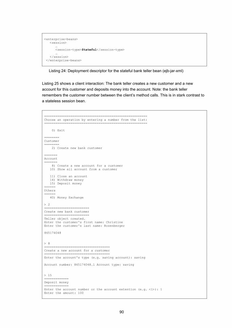
90
<enterprise-beans> <session> … <session-type>Stateful</session-type> … </session> </enterprise-beans>
Listing 24: Deployment descriptor for the stateful bank teller bean (ejb-jar-xml)
Listing 25 shows a client interaction: The bank teller creates a new customer and a new account for this customer and deposits money into the account. Note: the bank teller remembers the customer number between the client’s method calls. This is in stark contrast to a stateless session bean. ======================================================= Choose an operation by entering a number from the list: ======================================================= 0) Exit ======== Customer ======== 2) Create new bank customer ======= Account ======= 8) Create a new account for a customer 10) Show all account from a customer 11) Close an account 14) Withdraw money 15) Deposit money ====== Others ====== 40) Money Exchange > 2 ======================== Create new bank customer ======================== Teller object created. Enter the customer's first name: Christine Enter the customer's last name: Rosenberger 865174048 > 8 =================================== Create a new account for a customer =================================== Enter the account's type (e.g. saving account): saving Account number: 865174048.1 Account type: saving > 15 ============= Deposit money ============= Enter the account number or the account extention (e.g. <1>): 1 Enter the amount: 100

91
Successfully credited account: 100.0 > 10 ================================ Show all account from a customer ================================ customer name: Rosenberger account number: 865174048.1 account fund: 100.0 >
Listing 25: A Client Session with a Stateful Session Bean
6.4.5 Scenario 3: Customer and Account as Entity Beans
In the previous example, the situation is as follows: The bank teller takes a customer’s money, and as soon as the customer leaves the bank, the bank teller forgets all about this customer. In reality, however, a bank customer exists for months or years. Therefore, there it is necessary to store the customer’s data, his accounts and the money in the accounts. Changing the customer and account class into entity beans enables the container to save the state of those beans to a persistent storage.
6.4.5.1 Description The bank teller as a stateful session bean fits perfectly the application’s need of hosting the business methods. The “new” bank teller knows everything the second teller knew, and more. The customer bean is designed as a persistent bean; the bank teller can now return a list of all customers in the bank. It is possible to search for an existing customer by its first and/or last name, and besides crediting and charging an account, it is possible to transfer money between accounts.
6.4.5.2 Implementation Figure 50 shows the class diagram for the bank with the bank teller designed as a stateful session bean, and the customer and account bean as entity beans.
Server
<<stateful session>>BankTeller
<<entity>>Account
<<entity>>Customer
x
Figure 50: Class diagram for the bank with customer and account as entity beans
Only the new classes and methods are discussed in the following sections.
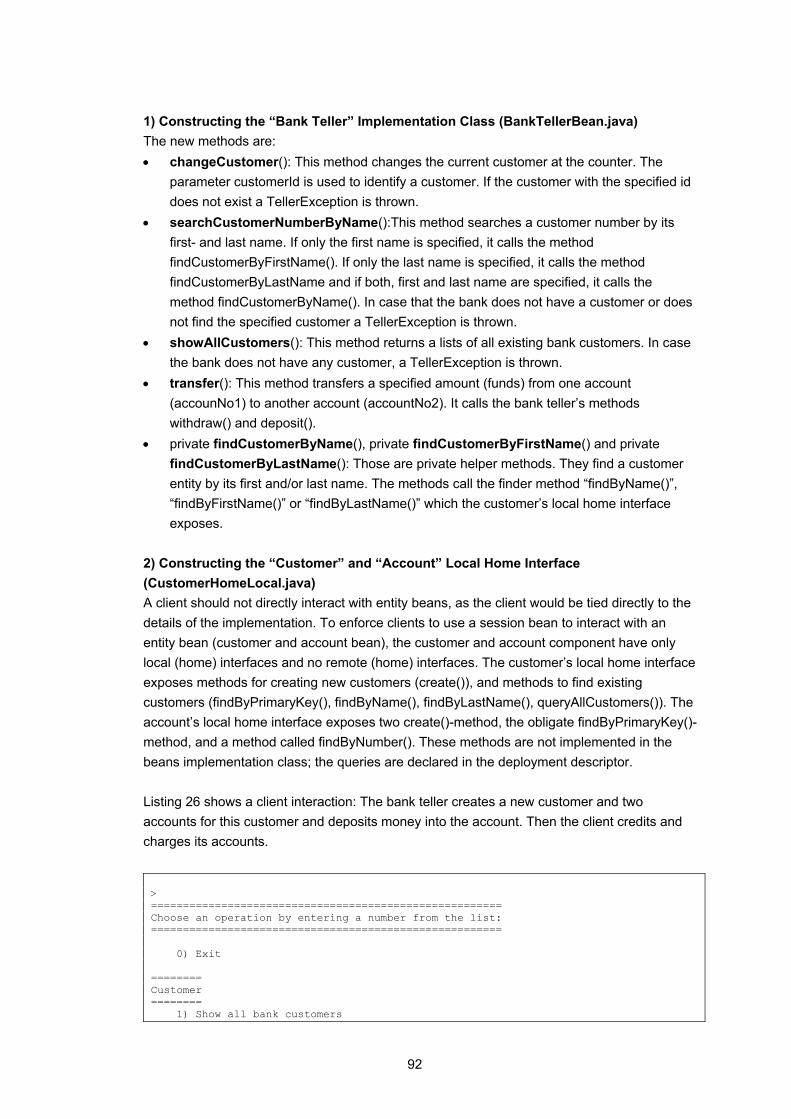
92
1) Constructing the “Bank Teller” Implementation Class (BankTellerBean.java) The new methods are: • changeCustomer(): This method changes the current customer at the counter. The
parameter customerId is used to identify a customer. If the customer with the specified id does not exist a TellerException is thrown.
• searchCustomerNumberByName():This method searches a customer number by its first- and last name. If only the first name is specified, it calls the method findCustomerByFirstName(). If only the last name is specified, it calls the method findCustomerByLastName and if both, first and last name are specified, it calls the method findCustomerByName(). In case that the bank does not have a customer or does not find the specified customer a TellerException is thrown.
• showAllCustomers(): This method returns a lists of all existing bank customers. In case the bank does not have any customer, a TellerException is thrown.
• transfer(): This method transfers a specified amount (funds) from one account (accounNo1) to another account (accountNo2). It calls the bank teller’s methods withdraw() and deposit().
• private findCustomerByName(), private findCustomerByFirstName() and private findCustomerByLastName(): Those are private helper methods. They find a customer entity by its first and/or last name. The methods call the finder method “findByName()”, “findByFirstName()” or “findByLastName()” which the customer’s local home interface exposes.
2) Constructing the “Customer” and “Account” Local Home Interface (CustomerHomeLocal.java) A client should not directly interact with entity beans, as the client would be tied directly to the details of the implementation. To enforce clients to use a session bean to interact with an entity bean (customer and account bean), the customer and account component have only local (home) interfaces and no remote (home) interfaces. The customer’s local home interface exposes methods for creating new customers (create()), and methods to find existing customers (findByPrimaryKey(), findByName(), findByLastName(), queryAllCustomers()). The account’s local home interface exposes two create()-method, the obligate findByPrimaryKey()-method, and a method called findByNumber(). These methods are not implemented in the beans implementation class; the queries are declared in the deployment descriptor. Listing 26 shows a client interaction: The bank teller creates a new customer and two accounts for this customer and deposits money into the account. Then the client credits and charges its accounts. > ======================================================= Choose an operation by entering a number from the list: ======================================================= 0) Exit ======== Customer ======== 1) Show all bank customers
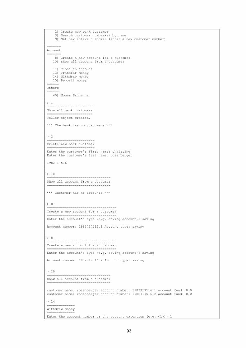
93
2) Create new bank customer 3) Search customer number(s) by name 9) Set new active customer (enter a new customer number) ======= Account ======= 8) Create a new account for a customer 10) Show all account from a customer 11) Close an account 13) Transfer money 14) Withdraw money 15) Deposit money ====== Others ====== 40) Money Exchange > 1 ======================= Show all bank customers ======================= Teller object created. *** The bank has no customers *** > 2 ======================== Create new bank customer ======================== Enter the customer's first name: christine Enter the customer's last name: rosenberger 1982717516 > 10 ================================ Show all account from a customer ================================ *** Customer has no accounts *** > 8 =================================== Create a new account for a customer =================================== Enter the account's type (e.g. saving account): saving Account number: 1982717516.1 Account type: saving > 8 =================================== Create a new account for a customer =================================== Enter the account's type (e.g. saving account): saving Account number: 1982717516.2 Account type: saving > 10 ================================ Show all account from a customer ================================ customer name: rosenberger account number: 1982717516.1 account fund: 0.0 customer name: rosenberger account number: 1982717516.2 account fund: 0.0 > 14 ============== Withdraw money ============== Enter the account number or the account extention (e.g. <1>): 1

94
Enter the amount: 1 Your balance is 0.0! You cannot withdraw 1.0! > 15 ============= Deposit money ============= Enter the account number or the account extention (e.g. <1>): 2 Enter the amount: 2 Successfully credited account: 2.0 > 14 ============== Withdraw money ============== Enter the account number or the account extention (e.g. <1>): 2 Enter the amount: 1 1.0 > 0 ==== Exit ====
Listing 26: Client session with an entity bean
6.4.6 Scenario 4: Deployment Descriptor
In the first scenario of the hands-on session, students must integrate an existing component (Phone) into the bank system. The phone component’s Java classes are already developed. Students must write the deployment descriptor, and compile and deploy the code by using the ant8 tool. Figure 51 shows the class diagram for the bank system with the component “Phone”.
Server
<<stateful session>>BankTeller
<<entity>>Phone
<<entity>>Account
<<entity>>Customer
xx
Figure 51: Class diagram for scenario 4 in the hands-on session
8 In order to compile the classes, to build the JAR file and to deploy the examples and exercises, a Java-based tool called “Ant” is used. The configuration files used by Ant are XML-based (the name of the file is build.xml), calling out a target tree. Ant provides many tasks to help compiling, archiving, copying with filtering etc. For more information about Ant see [55].
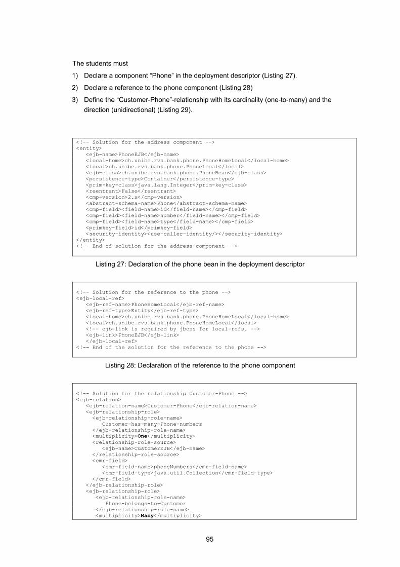
95
The students must
1) Declare a component “Phone” in the deployment descriptor (Listing 27).
2) Declare a reference to the phone component (Listing 28)
3) Define the “Customer-Phone”-relationship with its cardinality (one-to-many) and the direction (unidirectional) (Listing 29).
<!-- Solution for the address component --> <entity> <ejb-name>PhoneEJB</ejb-name> <local-home>ch.unibe.rvs.bank.phone.PhoneHomeLocal</local-home> <local>ch.unibe.rvs.bank.phone.PhoneLocal</local> <ejb-class>ch.unibe.rvs.bank.phone.PhoneBean</ejb-class> <persistence-type>Container</persistence-type> <prim-key-class>java.lang.Integer</prim-key-class> <reentrant>False</reentrant> <cmp-version>2.x</cmp-version> <abstract-schema-name>Phone</abstract-schema-name> <cmp-field><field-name>id</field-name></cmp-field> <cmp-field><field-name>number</field-name></cmp-field> <cmp-field><field-name>type</field-name></cmp-field> <primkey-field>id</primkey-field> <security-identity><use-caller-identity/></security-identity> </entity> <!-- End of solution for the address component -->
Listing 27: Declaration of the phone bean in the deployment descriptor
<!-- Solution for the reference to the phone --> <ejb-local-ref> <ejb-ref-name>PhoneHomeLocal</ejb-ref-name> <ejb-ref-type>Entity</ejb-ref-type> <local-home>ch.unibe.rvs.bank.phone.PhoneHomeLocal</local-home> <local>ch.unibe.rvs.bank.phone.PhoneHomeLocal</local> <!-- ejb-link is required by jboss for local-refs. --> <ejb-link>PhoneEJB</ejb-link> </ejb-local-ref> <!-- End of the solution for the reference to the phone -->
Listing 28: Declaration of the reference to the phone component
<!-- Solution for the relationship Customer-Phone --> <ejb-relation> <ejb-relation-name>Customer-Phone</ejb-relation-name> <ejb-relationship-role> <ejb-relationship-role-name> Customer-has-many-Phone-numbers </ejb-relationship-role-name> <multiplicity>One</multiplicity> <relationship-role-source> <ejb-name>CustomerEJB</ejb-name> </relationship-role-source> <cmr-field> <cmr-field-name>phoneNumbers</cmr-field-name> <cmr-field-type>java.util.Collection</cmr-field-type> </cmr-field> </ejb-relationship-role> <ejb-relationship-role> <ejb-relationship-role-name> Phone-belongs-to-Customer </ejb-relationship-role-name> <multiplicity>Many</multiplicity>
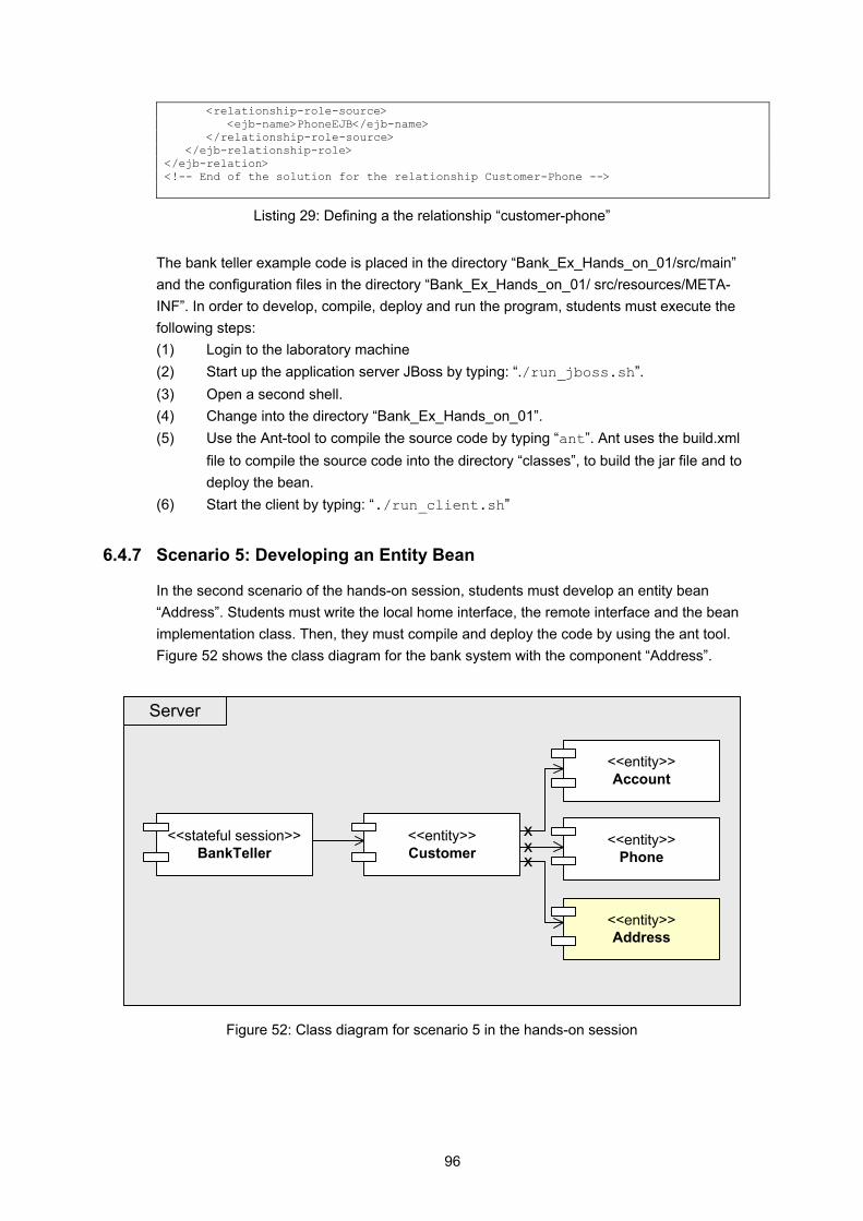
96
<relationship-role-source> <ejb-name>PhoneEJB</ejb-name> </relationship-role-source> </ejb-relationship-role> </ejb-relation> <!-- End of the solution for the relationship Customer-Phone -->
Listing 29: Defining a the relationship “customer-phone”
The bank teller example code is placed in the directory “Bank_Ex_Hands_on_01/src/main” and the configuration files in the directory “Bank_Ex_Hands_on_01/ src/resources/META-INF”. In order to develop, compile, deploy and run the program, students must execute the following steps: (1) Login to the laboratory machine (2) Start up the application server JBoss by typing: “./run_jboss.sh”. (3) Open a second shell. (4) Change into the directory “Bank_Ex_Hands_on_01”. (5) Use the Ant-tool to compile the source code by typing “ant”. Ant uses the build.xml
file to compile the source code into the directory “classes”, to build the jar file and to deploy the bean.
(6) Start the client by typing: “./run_client.sh”
6.4.7 Scenario 5: Developing an Entity Bean
In the second scenario of the hands-on session, students must develop an entity bean “Address”. Students must write the local home interface, the remote interface and the bean implementation class. Then, they must compile and deploy the code by using the ant tool. Figure 52 shows the class diagram for the bank system with the component “Address”.
Server
<<stateful session>>BankTeller
<<entity>>Account
<<entity>>Phone
<<entity>>Customer
<<entity>>Address
x
xx
Figure 52: Class diagram for scenario 5 in the hands-on session
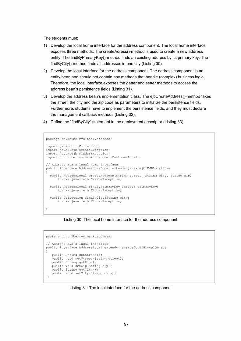
97
The students must:
1) Develop the local home interface for the address component. The local home interface exposes three methods: The createAdress()-method is used to create a new address entity. The findByPrimaryKey()-method finds an existing address by its primary key. The findByCity()-method finds all addresses in one city (Listing 30).
2) Develop the local interface for the address component. The address component is an entity bean and should not contain any methods that handle (complex) business logic. Therefore, the local interface exposes the getter and setter methods to access the address bean’s persistence fields (Listing 31).
3) Develop the address bean’s implementation class. The ejbCreateAddress()-method takes the street, the city and the zip code as parameters to initialize the persistence fields. Furthermore, students have to implement the persistence fields, and they must declare the management callback methods (Listing 32).
4) Define the “findByCity” statement in the deployment descriptor (Listing 33).
package ch.unibe.rvs.bank.address; import java.util.Collection; import javax.ejb.CreateException; import javax.ejb.FinderException; import ch.unibe.rvs.bank.customer.CustomerLocalH; // Address EJB's local home interface public interface AddressHomeLocal extends javax.ejb.EJBLocalHome { public AddressLocal createAddress(String street, String city, String zip) throws javax.ejb.CreateException; public AddressLocal findByPrimaryKey(Integer primaryKey) throws javax.ejb.FinderException; public Collection findByCity(String city) throws javax.ejb.FinderException; }
Listing 30: The local home interface for the address component
package ch.unibe.rvs.bank.address; // Address EJB's local interface public interface AddressLocal extends javax.ejb.EJBLocalObject { public String getStreet(); public void setStreet(String street); public String getZip(); public void setZip(String zip); public String getCity(); public void setCity(String city); }
Listing 31: The local interface for the address component
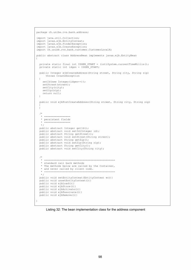
98
package ch.unibe.rvs.bank.address; import java.util.Collection; import javax.ejb.EntityContext; import javax.ejb.FinderException; import javax.ejb.CreateException; import ch.unibe.rvs.bank.customer.CustomerLocalH; public abstract class AddressBean implements javax.ejb.EntityBean { private static final int IDGEN_START = (int)System.currentTimeMillis(); private static int idgen = IDGEN_START; public Integer ejbCreateAddress(String street, String city, String zip) throws CreateException { setId(new Integer(idgen++)); setStreet(street); setCity(city); setZip(zip); return null; } public void ejbPostCreateAddress(String street, String city, String zip) { } /* * ================= * persistent fields * ================= */ public abstract Integer getId(); public abstract void setId(Integer id); public abstract String getStreet(); public abstract void setStreet(String street); public abstract String getZip(); public abstract void setZip(String zip); public abstract String getCity(); public abstract void setCity(String city); /* * ============================================== * standard call back methods * The methods below are called by the Container, * and never called by client code. * ============================================== */ public void setEntityContext(EntityContext ec){} public void unsetEntityContext(){} public void ejbLoad(){} public void ejbStore(){} public void ejbActivate(){} public void ejbPassivate(){} public void ejbRemove(){} }
Listing 32: The bean implementation class for the address component
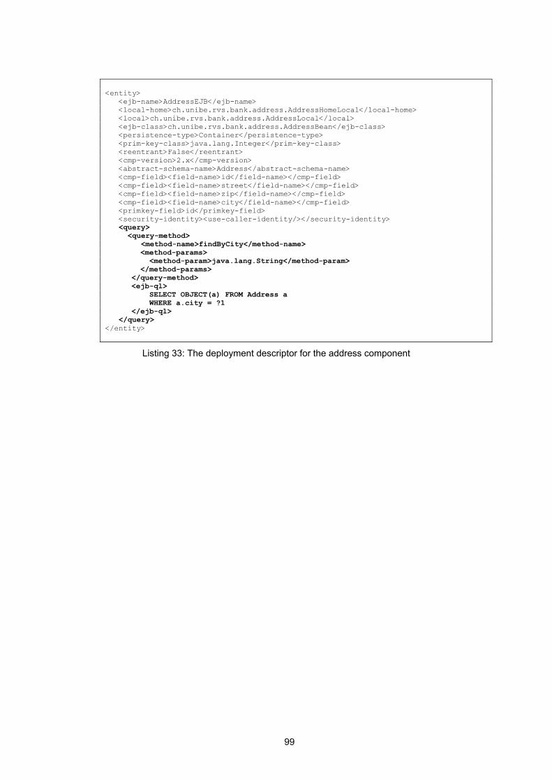
99
<entity> <ejb-name>AddressEJB</ejb-name> <local-home>ch.unibe.rvs.bank.address.AddressHomeLocal</local-home> <local>ch.unibe.rvs.bank.address.AddressLocal</local> <ejb-class>ch.unibe.rvs.bank.address.AddressBean</ejb-class> <persistence-type>Container</persistence-type> <prim-key-class>java.lang.Integer</prim-key-class> <reentrant>False</reentrant> <cmp-version>2.x</cmp-version> <abstract-schema-name>Address</abstract-schema-name> <cmp-field><field-name>id</field-name></cmp-field> <cmp-field><field-name>street</field-name></cmp-field> <cmp-field><field-name>zip</field-name></cmp-field> <cmp-field><field-name>city</field-name></cmp-field> <primkey-field>id</primkey-field> <security-identity><use-caller-identity/></security-identity> <query> <query-method> <method-name>findByCity</method-name> <method-params> <method-param>java.lang.String</method-param> </method-params> </query-method> <ejb-ql> SELECT OBJECT(a) FROM Address a WHERE a.city = ?1 </ejb-ql> </query> </entity>
Listing 33: The deployment descriptor for the address component
100
7 Related Work
7.1 Authentication, Authorization and Resource Reservation for Distributed Laboratories
“Authentication, Authorization and Resource Reservation for Distributed Laboratories” is a diploma thesis at University of Bern [8]. The VITELS hardware resources for the laboratory sessions are limited: An important goal was to provide access to the laboratory resources only to authorized participants. To achieve this goal, an online timetable and underlying scheduling script have been implemented. The e-learning modules offered by the VITELS project are provided to a closed user group. Each university can maintain its own student database needed for the VITELS authentication. In order to manage the e-learning participants, the proposed architecture in this work uses the Lightweight Directory Access Protocol (see 4.1.2). Furthermore, the security architecture for the VITELS project has been implemented and tested.
7.2 Internetportal für Computernetz-Praktika
“Internetportal für Computernetz-Praktika” is a diploma thesis at the University of Bern [12]. This work focuses on the transformation of an in-house laboratory exercise module (IP security) towards a remotely accessible course module [5]. A portal server that allows registered students to configure available Cisco Routers over a Web interface has been implemented. Moreover, the portal enables the students to access Linux-machines remotely and to measure network traffic. The portal has been integrated in the above mentioned reservation system (see 7.1).
7.3 The Virtual Internet and Telecommunications Laboratory of Switzerland
This paper introduces to the Virtual Internet and Telecommunications Laboratory of Switzerland (VITELS) course [9]. The VITELS course provides practical hands-on exercises for computer science students. The prerequisites to attend the VITELS courses are described, as well as the course contents. A short overview of the implementation architecture (see chapter 7.4) and the didactical approach (see 7.5) is given. At the end, the students’ experiences gained with the online courses are summarized.

101
7.4 Architectural Issues of a Remote Network Laboratory
This paper [5] describes the global architecture for the VITELS courses and remote laboratories. The course platform includes automated student data administration and a scheduling system. In addition, implementation issues (like security, error recovery and rating students) are discussed.
7.5 Didactical Issues of a Remote Network Laboratory
In order to get (at least) the same level of education in the remote courses as in a traditional one, many didactical issues have to be considered. In a first step, an in-house laboratory exercise module was extended towards a remotely accessible course module. This paper [6] describes the structure of the traditional and the remote exercises. The students’ experiences with both forms of learning were evaluated and the differences between them are pointed out.
7.6 VITELS, Didactics and Design Guide
The Didactics and Design Guide [7], a course development guide for the VITELS project, helps the topic experts to develop valuable content efficiently. The guides requirements and guidelines must be fulfilled by each VITELS module in order to provide a homogeneous course to the students [9]. The guide is described in chapter 3.
102
8 Discussion and Conclusions
This diploma thesis proved the usability of the VITELS architecture and the VITELS Didactics and Design Guide. It turned out that the VITELS architecture was well-designed and flexible enough to serve as blueprint for the two additional VITELS modules developed in this diploma thesis. Also, it was straightforward to integrate the learning material and the tests into the existing course platform. Adhering to the VITELS Didactics and Design Guide allowed me to focus on the module content rather than the visual design and the technical structure of the module, thus shortening the time needed to develop a module. In this thesis a set of third party software products for various tasks have been selected. Most of these software packages turned out to fit very well with the intended usage.
• For managing e-learning participants and scheduling laboratory sessions, the VITELS reservation system was successfully used [8].
• The portal for the hands-on sessions was implemented using the VITELS portal framework, a PHP based class and function library. Documentation of this framework was complete, well-structured and very helpful. The framework was also flexible enough to be customized and adapted to the special needs of the two modules implemented in this diploma thesis. Modifications were necessary to improve crash recovery for clients in the current laboratory session.
• The cleanup script, necessary to prepare the laboratory machines for a new student at the beginning of a laboratory session, was based on an existing cleanup script. This script was slightly modified to fit our needs.
• The hands-on sessions of the “Application Server”-module are based on the open source application server JBoss. Our positive experiences with this product support the view that JBoss is a stable and well-documented application server perfectly suitable in teaching environments.
Since both RMI and Application Servers will be part of the laboratory session of the lecture “Computer Networks”, both modules will be used in regular teaching activities at the University of Bern.
103
9 Outlook
This diploma thesis contributed two modules to the VITELS module portfolio. The list of available VITELS modules is not yet completed and further modules could be implemented. If the registration processes for the theoretical sections and the laboratory environments were easy and straightforward for all students in Switzerland, the range of the available modules could be improved. In fact, SWITCH, the Swiss Education and Research Network, recently activated a new Authentication and Authorisation Infrastructure (AAI) among the Swiss institutions of higher education, which facilitates the exchange of user information among these institutions. VITELS is one of the first e-learning projects that is adapted to the Swiss AAI, therefore an important technical obstacle for accessing VITELS will be removed. The subject application server is complex and cannot be completely covered in a twelve hour course. An additional module could be developed that covers further aspects of application server technologies, for instance, message driven beans, bean managed persistence (BMP) or bean managed transaction (BMT). The concepts of Remote Method Invocation could be explained based on the .NET Remoting API [57], instead of the Java RMI Framework, an equally viable real-world technology. Alternatively to using a J2EE application server to demonstrate the concept of application servers, hands-on sessions for Microsoft’s Transaction Server (MTS) and Microsoft’s COM+ could be prepared. Mindterm, the Java applet which is used as SSH client to access the laboratory machines, has some limitations: • Currently, it is not possible to transfer a file using secure copy (SCP). The workaround
consist of copying the content of the file by repeatedly invoking copy/paste. A better solution would be that Mindterm directly supports secure copy (SCP).
• Command completion using the tabulator key does not work in Mindterm. This should be fixed.
• Sometimes Mindterm freezes. In this case, the browser with the embedded Mindterm applet has to be restarted. The current session on the server is lost and there is certain danger, that intermediate work on the server is lost as well.
It is therefore recommended to look for possible alternatives to Mindterm. Such alternatives could either consist of another SSH client available as Java applet, or of a standalone SSH client. Currently, the scheduling approach for laboratory sessions is quite rigid. Students have to complete their laboratory sessions in one continuous period of time, possibly consisting of more than one adjacent time slot. A more flexible approach would allow them to reserve several non-continuous time slots, i.e. three hours at the beginning of the week and three hours at the end of the week. In this case, the laboratory management system would have to make sure students can recover from a previously started laboratory session at any time without loosing any intermediary data on the laboratory servers. Of course, such an approach would require a more sophisticated approach for managing student sessions and for preparing and backing up personal laboratory environments.
104
The current VITELS Didactics and Design guide defines that students must only have access to a standard web browser and an Internet connection in order to complete the hands-on sessions in the VITELS laboratory. Although this restriction is favourable in the sense that hands-on sessions are easily accessible from everywhere, it also means, that only a few basic tools are available to students and that the quality of the user interface of these tools is sometimes below current expectations. If this restriction was eased and hands-on sessions could require students to download and install software on their computer, the situation could be improved. In particular, hands-on sessions could provide standalone applications with graphical user interface to be installed on the student’s local computer, in order to access and test remote server components.
105
List of Figures
Figure 1: Structure of the Swiss Virtual Campus................................................................................... 14 Figure 2: Networking among the Higher Education Institutions ............................................................ 16 Figure 3: Global architecture for the VITELS course ............................................................................ 17 Figure 4: Layout for e-learning Modules [24]......................................................................................... 21 Figure 5: The position map for the remote method invocation module................................................. 22 Figure 6: The mind map for the remote method invocation module...................................................... 22 Figure 7: WebCT notes - list.................................................................................................................. 25 Figure 8: LDAP server acting as a gateway to an X.500 server ........................................................... 26 Figure 9: Stand-alone LDAP Server...................................................................................................... 27 Figure 10: Sample PHP script (show-user.php).................................................................................... 28 Figure 11: Output of sample PHP script (show-user.php)..................................................................... 29 Figure 12: Rendered output of sample PHP script................................................................................ 29 Figure 13: 2-tier architecture (web application) ..................................................................................... 30 Figure 14: Hosting the business logic in a 2-tier architecture ............................................................... 31 Figure 15: A 3-tier architecture.............................................................................................................. 31 Figure 16: Students work on their local machines ................................................................................ 32 Figure 17: Simulation on one dedicated machine ................................................................................. 33 Figure 18: Client- and server program on dedicated machines ............................................................ 34 Figure 19: The architecture for the “Application Server”-module .......................................................... 36 Figure 20: The scheduling system for the VITELS course.................................................................... 38 Figure 21: Administration menu ............................................................................................................ 39 Figure 22: Modified portal for the hands-on session ............................................................................. 40 Figure 23: The login page to the client- and server machine................................................................ 41 Figure 24: SSH session with the “Server” ............................................................................................. 42 Figure 25: Modules and objects in RMI [2]............................................................................................ 46 Figure 26: Table of contents for the RMI-module.................................................................................. 47 Figure 27: Possible representation of a remote object reference ......................................................... 48 Figure 28: Remote object with remote and local interface .................................................................... 49 Figure 29: Stub and skeleton................................................................................................................. 50 Figure 30: Object serialization............................................................................................................... 52 Figure 31: Class diagram for the game “Fazuul”................................................................................... 54 Figure 32: The student’s tasks in scenario 1: Client programming ....................................................... 56 Figure 33: Class diagram for the game “Mastermind”........................................................................... 59 Figure 34: New game scenario (sequence diagram) ............................................................................ 61 Figure 35: The students tasks in scenario 2: Server programming ...................................................... 62 Figure 36: Table of contents for the “Application Server”-module......................................................... 68 Figure 37: A Java 2, Enterprise Edition (J2EE) deployment [1] ............................................................ 69 Figure 38: An object model for a component (in this case a stateless session bean) .......................... 70 Figure 39: UML sequence diagram for accessing a bean..................................................................... 73 Figure 40: Life cycle of a stateless session bean [4]............................................................................. 74 Figure 41: Life cycle of a stateful session bean [4] ............................................................................... 75 Figure 42: Life cycle of an entity bean [4].............................................................................................. 76 Figure 43: Unidirectional relationship between entity beans................................................................. 79

106
Figure 44: Bidirectional relationship between entity beans ................................................................... 79 Figure 45: One-to-one relationship (unidirectional) ............................................................................... 79 Figure 46: One-to-many relationship (unidirectional) ............................................................................ 80 Figure 47: Many-to-many relationship, bidirectional ............................................................................. 80 Figure 48: Class diagram for the bank teller as a stateless session bean............................................ 85 Figure 49: Class diagram for the bank teller as a stateful session bean .............................................. 88 Figure 50: Class diagram for the bank with customer and account as entity beans............................. 91 Figure 51: Class diagram for scenario 4 in the hands-on session ........................................................ 94 Figure 52: Class diagram for scenario 5 in the hands-on session ........................................................ 96

107
Listings
Listing 1: The JNDI property file with the URL “localhost”..................................................................... 36 Listing 2: The JNDI property file with the URL “kif.unibe.ch”................................................................. 36 Listing 3: Content of the file “/root/user1” on the gateway..................................................................... 41 Listing 4: The cleanup script for the server and for the client machine (RMI)....................................... 43 Listing 5: The sudoer file ....................................................................................................................... 43 Listing 6: Command to start the registry................................................................................................ 56 Listing 7: Command to start the server ................................................................................................. 56 Listing 8: Client program........................................................................................................................ 57 Listing 9: Command to start the client ................................................................................................... 57 Listing 10: Typical client session ........................................................................................................... 58 Listing 11: The bash file to run the client............................................................................................... 61 Listing 12: Binding the “Mastermind”-object to the RMI registry ........................................................... 63 Listing 13: Creating the RMI registry on the specified port ................................................................... 63 Listing 14: Setting the security manager ............................................................................................... 63 Listing 15: Constructor of the MastermindRowImpl-class ................................................................. 63 Listing 16: Creation of a non-remote-object .......................................................................................... 64 Listing 17: Compiling the Java classes and generating stubs and skeletons ....................................... 64 Listing 18: Starting the server................................................................................................................ 64 Listing 19: A typical client session......................................................................................................... 65 Listing 20: ejb-jar.xml file for a stateless session bean ......................................................................... 72 Listing 21: Virtual fields declared in the implementation class .............................................................. 78 Listing 22: ejb-jar.xml file for a stateless session bean ......................................................................... 86 Listing 23: A client session .................................................................................................................... 87 Listing 24: Deployment descriptor for the stateful bank teller bean (ejb-jar-xml) .................................. 90 Listing 25: A Client Session with a Stateful Session Bean.................................................................... 91 Listing 26: Client session with an entity bean........................................................................................ 94 Listing 27: Declaration of the phone bean in the deployment descriptor .............................................. 95 Listing 28: Declaration of the reference to the phone component ........................................................ 95 Listing 29: Defining a the relationship “customer-phone”...................................................................... 96 Listing 30: The local home interface for the address component.......................................................... 97 Listing 31: The local interface for the address component.................................................................... 97 Listing 32: The bean implementation class for the address component ............................................... 98 Listing 33: The deployment descriptor for the address component ...................................................... 99
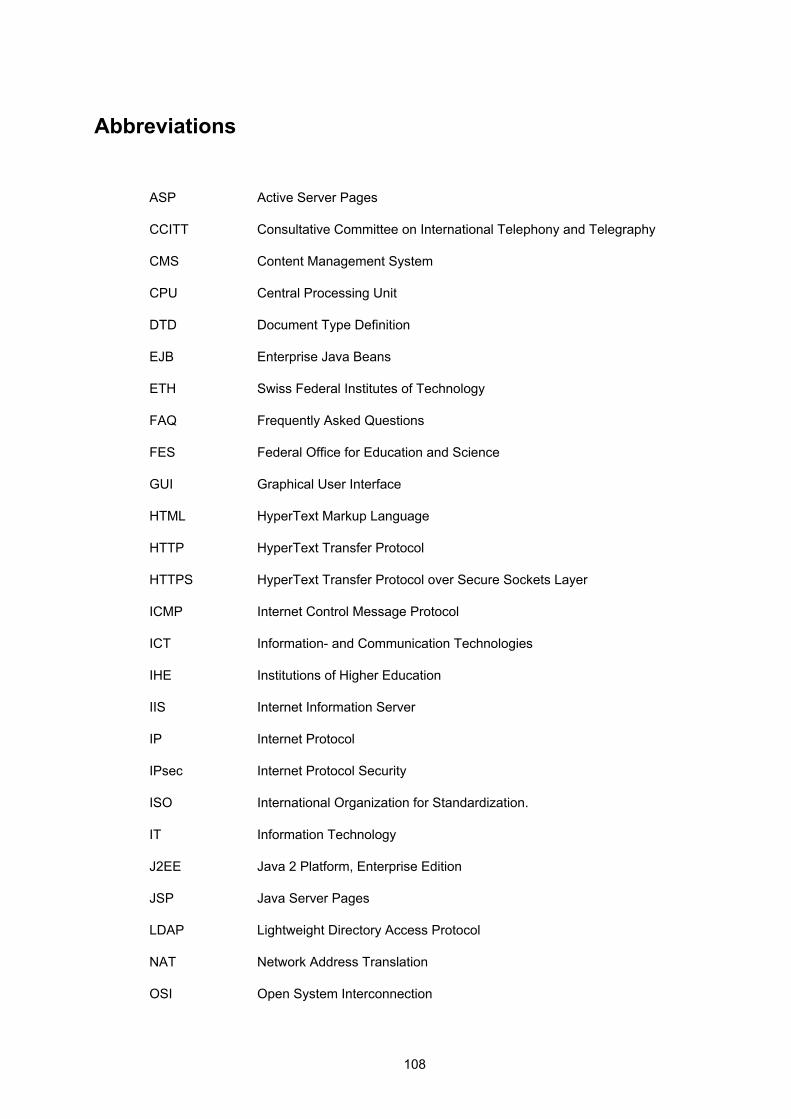
108
Abbreviations
ASP Active Server Pages
CCITT Consultative Committee on International Telephony and Telegraphy
CMS Content Management System
CPU Central Processing Unit
DTD Document Type Definition
EJB Enterprise Java Beans
ETH Swiss Federal Institutes of Technology
FAQ Frequently Asked Questions
FES Federal Office for Education and Science
GUI Graphical User Interface
HTML HyperText Markup Language
HTTP HyperText Transfer Protocol
HTTPS HyperText Transfer Protocol over Secure Sockets Layer
ICMP Internet Control Message Protocol
ICT Information- and Communication Technologies
IHE Institutions of Higher Education
IIS Internet Information Server
IP Internet Protocol
IPsec Internet Protocol Security
ISO International Organization for Standardization.
IT Information Technology
J2EE Java 2 Platform, Enterprise Edition
JSP Java Server Pages
LDAP Lightweight Directory Access Protocol
NAT Network Address Translation
OSI Open System Interconnection

109
PHP PHP Hypertext Preprocessor
RIP Routing Information Protocol
RMI Remote Method Invocation
RPC Remote Procedure Call
RVS Rechnernetze und Verteilte Systeme
SC Steering Committee
SSH Secure Shell
SSL Secure Socket Layer
SUC Swiss University Conference
SVC Swiss Virtual Campus
TCP/IP Transmission Control Protocol/Internet Protocol
UAS Swiss Universities of Applied Sciences
UDP User Datagram Protocol
URL Uniform Resource Locator
VM Java Virtual Machine
VPN Virtual Private Network
VITELS Virtual Internet and Telecommunications Laboratory of Switzerland
WBT Web Based Training
WWW World Wide Web

110
Glossary
Apache is a very common web server running on Unix, Linux and Windows.
Authentication is the process of determining whether someone or something is, in fact, who or what it is declared to be.
Authorisation is the process of giving someone permission to do something. Usually, this is done after successful authentication.
Cron Job A cron job specifies a program and a point of time when the given program is automatically run by the cron daemon.
Directory Service A directory is similar to a database, but tends to contain more descriptive, attribute-based information. The information in a directory is generally read much more often than it is written. As a consequence, directories don't usually implement the complicated transaction or roll-back schemes that regular databases use. Directories are tuned to give quick responses to high-volume lookup or search operations.
DTD Document Type Definition. A DTD states what tags and attributes are used to describe content in an SGML, XML or HTML document, where each tag is allowed, and which tags can appear within other tags.
Encryption The translation of data into a secret code. Encryption is the most effective way to achieve data security. To read an encrypted file, the user must have access to a secret key or password that enables him to decrypt it.
GUI Graphical User Interface. A program interface that takes advantage of the computer's graphics capabilities to make the program easier to use.
Middleware Software that connects two otherwise separate applications.
OSI Open System Interconnection. An ISO standard for worldwide communications that defines a networking framework for implementing protocols in seven layers. Control is passed from one layer to the next, starting at the application layer in one station, proceeding to the bottom layer, over the channel to the next station and back up the hierarchy.
IP Internet Protocol. IP specifies the format of packets, also called datagrams, and the addressing scheme. It allows addressing a package and dropping it in the system, but there's no direct link between the sender and the recipient.
IPsec Internet Protocol Security. IPsec is a developing standard for security at the network or packet layer of network communication. IPsec is especially useful for implementing virtual private networks and for remote user access through dial-up connection to private networks.
111
ISO International Organization for Standardization. Note that ISO is not an acronym; instead, the name derives from the greek word iso, which means equal. Founded in 1946, ISO is an international organization composed of national standards bodies from over 75 countries.
LDAP Lightweight Directory Access Protocol. Directories containing information such as, for such as, for example, names, phone numbers and addresses. LDAP provides a relatively simple protocol for updating and searching such directories. See Directory Service.
NAT Network Address Translation, an Internet standard that enables a Local Area Network (LAN) to use one set of IP addresses for internal traffic and a second set of addresses for external traffic. A NAT box located where the LAN meets the Internet makes all necessary IP address translations.
Open Source Open Source refers to the fact that the source code of Free Software is open to the world to take, to modify and to reuse.
PHP PHP Hypertext Preprocessor (PHP) is a scripting language that is especially suited for web development and can be embedded into HTML.
Protocol An agreed-upon format for transmitting data between two devices. The protocol determines the type of error checking to be used, data compression method, how the sending device will indicate that it has finished sending a message and how the receiving device will indicate that it has received a message.
RIP Routing Information Protocol. An interior gateway protocol defined by RFC 1058 that specifies how routers exchange routing table information. With RIP, routers periodically exchange entire tables.
Socket In UNIX and some other operating systems, a software object that connects an application to a network protocol. In UNIX, for example, a program can send and receive TCP/IP messages by opening a socket and reading and writing data to and from the socket. This simplifies program development because the programmer need only worry about manipulating the socket and can rely on the operating system to actually transport messages across the network correctly.
SSL Secure Sockets Layer (SSL): A security protocol that provides communications privacy over the Internet. The protocol allows client/server applications to communicate in a way that is designed to prevent eavesdropping, tampering, or message forgery.
Sniffing Network sniffing is the process of gathering information (from a network) that is designated for someone else.
Telnet A terminal emulation program for TCP/IP networks such as the Internet.
112
The Telnet program runs on the client computer and connects it to a server on the network. The user can then enter commands through the Telnet program and they will be executed as if the user was entering them directly on the server console.
VM Virtual Machine: A self-contained operating environment that behaves as if it is a separate computer.
VPN A virtual private network is a private data network that makes use of the public telecommunication infrastructure, maintaining privacy through the use of a tunnelling protocol and security procedures.

113
Bibliography
[1] Mastering Enterprise Java Beans and J2EE, Ed Roman, Wiley, 1999
[2] Distributed Systems, Concepts and Design, George Coulouris, Jean Dollimore, Tim Kindberg Addison-Wesley, 2001
[3] Database Programming with JDBC and JAVA, Georges Reese, O’Reilly, 1997
[4] Enterprise JavaBeans, Developing Enterprise Java Components, Richard Monson-Haefel, O’Reilly, 2001
[5] M.-A. Steinemann, S. Zimmerli, T. Jampen, T. Braun: Architectural Issues of a Remote Network Laboratory, Networked Learning 2002 (NL 2002), Berlin, Germany, May 1-4, 2002, ISBN 3-906454-31-2, pp. 133
[6] M.-A. Steinemann, T. Jampen, S. Zimmerli, T. Braun: Didactical Issues of a Remote Network Laboratory, 4th International Conference on New Educational Environments (ICNEE 02), Lugano, Switzerland, May 8-11, 2002, ISBN 3-0345-0031-9
[7] M.-A. Steinemann, A. Weyland, J. Viens, T.Braun: VITELS Didactics and Design Guide, April 2003
[8] Thomas Jampen, Authentication, Authorization and Resource Reservation for Distributed Laboratories, June 2002, Institut für Informatik und angewandte Mathematik der Universität Bern
[9] Torsten Braun and Marc-Alain Steinemann, The Virtual Internet and Telecommunications Laboratory of Switzerland, ACM SIGCOMM 2003, August 25-29, 2003, Karlsruhe, Germany.
[10] Stefan Zimmerli, Marc-Alain Steinemann and Torsten Braun, Resource Management Portal for Laboratories Using Real Devices on the Internet, Computer Communications Review Vol. 33 Issue 3, pp. 145-151, ISSN: 0146-4833, July 2003.
[11] Thomas Jampen, VITELS – HOWTO, Graphical User Interface for VITELS Scheduling, Institut für Informatik und angewandte Mathematik der Universität Bern
[12] Stefan Zimmerli, Internetportal für Computernetze-Praktika, 2002, Institut für Informatik und angewandte Mathematik der Universität Bern
[13] Christine Rosenberger, Attila Weyland, Günther Stattenberger: Remote
114
Method Invocation, Hands-on Session Hardware Setup, Institut für Informatik und angewandte Mathematik der Universität Bern
[14] VITELS - an acronym for a modern e-learning course
[15] Directories and X.500: An Introduction, Barbara Shuh, Network Notes #45, ISSN 1201-4338, Information Technology Services, National Library of Canada, March 14, 1997
[16] IBM: Understanding LDAP, Heinz Johner, Larry Brown, Franz-Stefan Hinner, Wolfgang Reis, Johan Westman, June 1998
[17] Swiss Federal Office for Professional Education and Technology (OPET).
http://www.bbt.admin.ch/e/index.htm
[18] Swiss Federal Office for Education and Science
http://www.bbw.admin.ch
[19] Swiss Virtual Campus http://www.virtualcampus.ch
[20] Swiss University Conference http://shkwww.unibe.ch/
[21] Virtual Internet and Telecommunications Laboratory of Switzerland http://www.vitels.ch
[22] WebCT http://www.webct.com/
[23] Sudo in a Nutshell http://www.courtesan.com/sudo/intro.html
[24] Attila Weyland, personal communication
[25] AK Wien http://www.akwien.at/dat/elearning_leitfaden.pdf
[26] Line Zine http://www.linezine.com/elearning.htm
[27] Mindterm: SSH Client http://www.mindbright.se/mindterm/
115
[28] TECFA, Technologies de Formation et Apprentissage http://tecfa.unige.ch
[29] University of Bern http://www.unibe.ch/
[30] Centre Universitaire d’Informatique http://cui.unige.ch/
[31] University of Applied Sciences of Fribourg http://www.eif.ch/
[32] L’Université de Fribourg http://www.unifr.ch/home/intranet.php
[33] University of Neuchatel http://www.unine.ch/info/welcome.htm
[34] The University of Melbourne http://www.law.unimelb.edu.au/multimedia/what-
is/interactivity.html
[35] Official Microsoft ASP.NET http://www.asp.net/
[36] Hypertext Preprocessor http://www.php.net/
[37] Java Server Pages http://java.sun.com/products/jsp/
[38] Mastermind http://kal-el.ugr.es/~jmerelo/newGenMM/node1.html
[39] General Introduction and FAQ http://webct.unibe.ch/
[40] Prof. Dr. Torsten Braun, Institute of Computer Science and Applied Mathematics (IAM), Universität Bern http://www.iam.unibe.ch/~braun/
[41] Prof. Bernard Levrat, Centre Universitaire d'Informatique, Université de Genève
116
http://cui.unige.ch/~levrat/
[42] Bernard LEVRAT, The Swiss Virtual Campus: present situation and challenges http://eee.uci.edu/programs/ifipconf/papers/levrat/
[43] Swissup http://www.swissup.com/art_content.cfm
[44] Dr. Franziska B. Marti 2nd International Conference on NEW LEARNING TECHNOLOGIES, Berne, 8-30/31-1999
[45] How SSL Works http://developer.netscape.com/tech/security/ssl/howitwork
s.html
[46] Secure Shell http://www.ssh.com/
[47] OpenLDAP http://www.openldap.org/
[48] Lightweight Directory Access Protocol. http://www.ietf.org/rfc/rfc1777.txt
[49] Apache ASP
http://www.apache-asp.org/
[50] Sun ONE Active Server Pages 4.0 http://wwws.sun.com/software/chilisoft/index.html
[51] CRUS : Rector’s Conference of the Swiss Universities
http://www.crus.ch/deutsch/Nachw/
[52] SNI-RSI : Swiss Network for Innovation
http://www.sni-rsi.ch/english/main_e.html
[53] XDoclet
http://xdoclet.sourceforge.net/
[54] JBoss Group
117
http://www.jboss.org/
[55] The Apache Ant Project
http://jakarta.apache.org/ant
[56] Hyper dictionary
http://www.hyperdictionary.com/dictionary/distributed+sys
tem
[57] Richard Wiener: “Remoting in C# and .NET”, in Journal of Object Technology, vol. 3, no. 1, January-February 2004, pp. 83-100. http://www.jot.fm/issues/issue_2004_01/column