theory and tunnel tests of rotor blades for...
TRANSCRIPT
M I N I S T R Y OF A V I A T I O N
R. & M. No . 3275~
'\ \,.
A E R O N A U T I C A L R E S E A R C H C O U N C I L
R E P O R T S AND M E M O R A N D A
Theory and Tunnel Tests of Rotor Blades for Supersonic Turbines By B. S. STRATFORD and G. E. SANSOME
L O N D O N : HER M A J E S T Y ' S S T A T I O N E R Y O F F I C E
I962
SEVENTEEN SHILLINGS NET

Theory and Tunnel Tests of Rotor Blades for Supersonic Turbines
By B. S. STRATFORD and G. E. SANSOME
COMMUNICATED BY THE DEPUTY CONTROLLER AIRCRAFT (RESEARCH AND DEVELOPMENT),
MINISTRY OF AVIATION
Reports and Memoranda No. 3275* December, z96o
Summary. In special circumstances where a large work output is required from a turbine in a single stage
it is necessary to us e high pressure ratios across the nozzle blades, thus producing supersonic velocities at inlet to the rotor. As part of an investigation into such turbines, several designs for the inter-blade passages of
the rotor have been tested in a two-dimensional tunnel, a design theory being developed concurrently. The first design, featuring constant passage width and curvature as in steam-turbine practice, but having
thin leading and trailing edges, was found to suffer from focusing of the compression waves from the concave surface, with consequent flow separation from the opposite convex surface. I t gave a velocity coefficient of
0" 929--based upon the area-mean total pressure as measured at an inlet Mach number of 1.90 and turning angle of 140 deg. The measured value compares favourably with values from previous steam tests; where the results have been in the range from 0.65 to 0.92.
From theoretical reasoning, and from additional test observations, a subsequent passage was designed having an inlet transition length of small curvature, leading to a free-vortex passage of double the transition curvature; a small amount Of contraction was incorporated. Schlieren photographs showed the flow in this passage to be almost shock free. A thin region of low-energy air existed close to the convex surface, but liquid- injection tests located only one small bubble of reversed flow. Pressure traverses at exit indicated a velocity coefficient of 0. 952, based on the area-mean total pressure. When a!lowance is made for turning angle and Reynolds number this result appears to compare quite favourably with previous work.
I t would seem that the optimum blade pitching in a turbine would be about 20 to 30 per cent closer than in a two,dimensional cascade. However, the resultant pitching tends to become very close, except at very large turning angles, with the result that in some applications difficulties could arise in the practical design and manufacture.
Several uncertainties remain and the present design must be regarded as still experimental.
1.0. Introduction. For certain applications, such as s team-plant auxiliaries, ' as te rn ' turbines in
marine s team plant, or the drive of fuel p u m p s for l iquid-propel lant rockets, turbines are reqmred
to give a very large work output in a single stage. Impu l se wheels are usually employed, so that the
whole of the expansion occurs across the nozzles. T h e gas f rom the nozzles enters the rotor at a
* Previously issued as N.G.T.E. Report No. 245--A.R.C. 22,537.
supersonic relative velocity and a largeswirl angle, to be turned through an angle of the order of
90 to 160 deg. Previous reports have described the design and testing of such a turbine at the
National Gas Turbine Establishment 1 and the tunnel performances of the supersonic nozzles ~.
The present Report describes the tunnel investigation of the first row of rotor blades, wherein is
thought to reside the major source of loss--see, for example, Refs. 1 to 4. The design requirements
demanded a relative inlet Mach number to the rotor of 1.90 and a turning angle of 140 deg, the
inlet and outlet swirl angles being equal at 70 deg (relative to the axia ! direction).
The main experimental work in the present Report is represented by Figs. 1, 5, 18 and 22, while
the main theoretical arguments are represented by Figs. 10 and 13; the qualifications given in the text are needed, however, when applying Figs. 10 and 13.
2.0. The Cascade Tunnel. The apparatus, shown in Fig. 1, consisted of a closed-jet two-
dimensional wind tunnel of Mach number 1.90, constructed of wood and Perspex and containing in the cascade a single blade and two passages. A Holland exhauster powered the tunnel, to which air
was supplied by a dry-air plant at just above atmospheric pressure and at a nominal dew point of - 80 deg C. A 1 deg diverging section at the Cascade outlet, followed by a subsonic diffuser, allowed the tunnel to be operated at an overall pressure ratio of 1.8--almost in silence. The Perspex forming the side walls fulfilled the dual purpose of holding the blade and providing Schlieren windows. As such it gave an unobstructed field of vision and an inexpensive mode of construction. The Schlieren views were readily examined on the rig so that, with the preceding advantages, it was decided to accept the photographic imperfections resulting from the susceptibility of Perspex to scratching.
Of the two passages in the cascade the test passage was the inner one. The flow at its entry consists of a uniform mainstream, together with a boundary layer which has grown in the nozzle and which is
approaching the convex surface of the passage. The uniform flow represents that in the turbine downstream of the pattern of bow waves 2 (strictly it should therefore be at a slightly higher Mach
number than the flow upstream of the bow waves in the turbine). The boundary layer should well
represent that which would approach the convex portion of a blade, after growing on the flat region
of the blade immediately upstream. Since in supersonic flow there can be no interaction between
neighbouring passages, other than by the wave patterns upstream and downstream, the flow in the inner passage of the tunnel should be typical of that in an infinite cascade. The upstream and down-
stream wave patterns, and hence the incidence and outlet angle, may be considered almost independently of the internal flow as, for example, in Refs. 1 and 2.
The second passage in the test cascade, the outer, acts as a by-pass for the boundary layer from
the other profiled wall of the nozzle. The outer passage is not representative of a passage in an
infinite cascade because of this boundary layer and because it traps the bow waves from the single
blade. In an infinite two-dimensional cascade having, as here, a subsonic axial component of velocity, the bow waves all pass upstream from the rotor rather than being trapped within the passages. In all the present tests in which supersonic flow was established the flow separated from the convex surface of the outer passage; consequently this passage has been deleted from most of the Schlieren photographs in order to avoid confusion.
All the tests were performed at zero incidence relative to the flat region of the blade upper surface. Such, it is felt, is the condition which holds locally in the turbine, i.e., at the leading edges and at the passage entry, downstream of the rotor bow wave 1, ~
The traversing instruments are sketched in Fig. 2. The static probe with the annular slot was
used for the earlier traverses, but was found to have a slight error resulting from a 0. 002 in. step (unintentional) at the slot. Consequently, as discussed in Ref. 2, the static probe with the four holes was used for the later traverses, from which all the main results are quoted, and it is thought 2
that the readings from this instrument were accurate.
The velocity coefficients quoted are based on the area-mean total pressure, the relationship between pressure coefficient and velocity coefficient at M - - 1.9 being shown in Fig. 3. Both coefficients take values for isentropic flow as datum as discussed in Ref. 2. In typical flows the velocity
coefficient based on the area-mean total pressure is close in value to the momentum-mean velocity
coefficient, i.e., to a coefficient "based on the mass mean of velocity.
The main tests were carried out without tip clearance, at a Reynolds number based on chord of 1" 3 x 10 6.
3.0. A Blade Design based on Steam- Turbhze Practice. The first blade profile to be tested was
that designed for the turbine 1, the design having been carried out mainly on the basis of practice in
steam plant. The profile, shown in Fig. 4, provides a passage having a constant width, w, and a
centre-line of constant radius of curvature, rm; w/r m = 0" 33, while the pitch/chord ratio, sic --- O. 47.
The upper surface of the blade at the leading and trailing edges is parallel to the nominal gas flow
at inlet and outlet respectively, except for the 20 deg chamfer at the edges themselves, which are
very thin.
In the turbine the chord and maximum thickness of the blades are constant throughout their
height, with the result that the passages between the blades diverge towards the tips. The section
tested two-dimensionally in the tunnel and shown in Fig. 4 was a four times magnification of that
in the turbine at mid-blade height. The aspect ratio of the blade was approximately the same as for
the turbine, the span in the tunnel being 3.11 in. and the chord 4 in.
Besides being tested in the 'turbine configuration' shown in Fig. 4 the design was also tested reversed, so that the 10 deg cut-back shown at the leading edge was transferred to the trailing edge, while the tangent to the concave surface at the leading edge became parallel to the oncoming flow'. This second arrangement is referred to as the 'cascade configuration'.
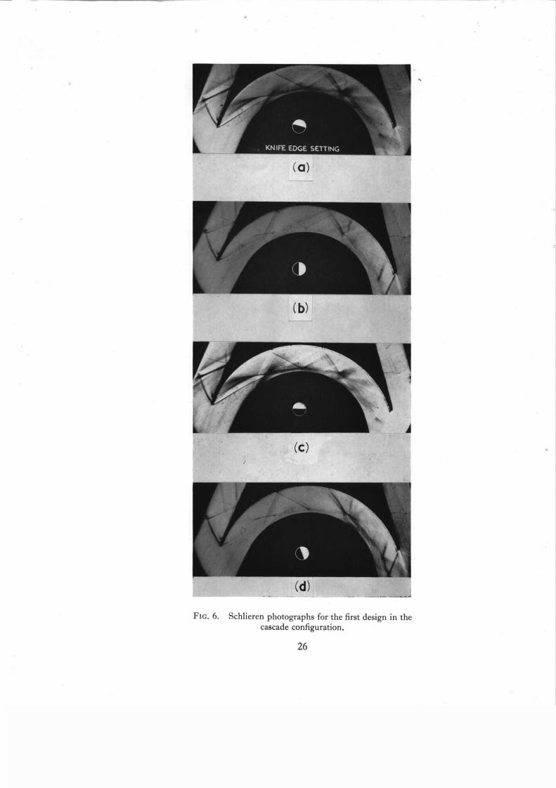
3.1 Results from the First Design. The main results are shown in Figs. 5 to 8. The Schlieren photographs show a focusing of the compression waves from the forward region
of the concave surface and suggest that, resulting from the focusing, there is a strong separation from the convex surface. Subsequent tests injecting small quantities of methylated spirits confirmed the
presence of separation and reverse flow for about a ½ in. length Of the convex surface. In the region
near mid-chord, where the photographs indicate the vortex sh~eet to have returned close to the
surface, the flow at the wall was found to be a mixture of forward and reversed flow.
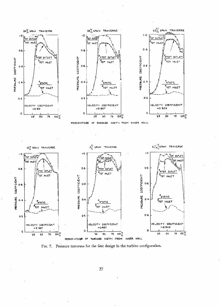
Near the convex wall at the passage exit the measured total and static pressures are very nearly
identical for most of the span, indicating a region of almost stagnant air. This region accounts for
most of the deficiency in velocity coefficient. In the turbine configuration the region for which the
dynamic head is less than a half that of the mainstream ranges from approximately 20 per cent of the
passage width at 2½ per cent span, .rising to a maximum of 35 per cent at 20 per cent span and
decreasing to 30 per cent of the passage width at mid-span. There is good agreement between the
width of these areas of large total-pressure loss, as seen in the traverses, and the distance between the
wall and the apparent vortex sheet as seen in the photographs of Fig. 5, measurement of this distance
3
(84943) A 2

in the photographs indicating that it extends over 30 to 35 per cent of the passage width. The mean velocity coefficient for the whole span, for the blade in the turbine configuration, is given by Fig. 8 to be approximately 0.93.
The results for the cascade configuration were not so consistent as for the turbine configuration.
They gave a mean velocity coefficient of approximately 0.90, the greater loss measured in comparison with the turbine configuration being the result of apparently wider regions of high-loss air adjacent to the convex wall in the traverses. However, the Schlieren photographs suggest that the width of the high-loss region should be about the same for both configurations. Since the photographs are consistent with the traverses for the turbine configuration and since the traverses for the cascade configuration were performed very early in the experimental programme, when the special care needed was not fully appreciated (see Section 8.0), the results for the turbine configuration are considered reasonably reliable, while thbse for the cascade configuration are regarded with reservation. Actually, for the turbine configuration, a partial repeat pitot traverse using the static traverse from the main test of this configt~ration for converting the pitot pressures to total pressures, gave a velocity coefficient about 0-015 higher than in the main test, but the discrepancy was not appreciated early enough to be investigated further.
From Figs. 5 and 6 the focusing is perhaps more severe for the cascade configuration than for the turbine configuration.
4.0. Theoretical Analysis and Intermediate Testing. In the present section an attempt will be made to analyse approximately, but in general terms, the supersonic flow in curved passages. The flow at the entry to the passages is assumed to be straight, and of uniform Mach number M 0. Consideration is at first limited to passages of very small curvatures.
In a passage of constant curvature the pressure distribution on either surface has the zig-zag
form of Fig. 9, as may be seen from consideration of the characteristics pattern. Thus, in what
may be termed the 'entry region', i.e., ABCD of Fig. 9, the pressure will decrease roughly linearly
through the expansion waves along AB until, at B, the compression waves start becoming incident from CD. Along BE the expansion waves which would be caused by the curvature of BE just cancel
the reflections of the compression waves from CD but the compression waves themselves remain.
Thus the pressure rises along BE until, at E, it has returned to its entry value, i.e., that at A. The same pattern is repeated along the next section of surface, EGI, while the corresponding (equal and opposite) pressure changes occur along the concave surface. The resulting zig-zag pressure distribution subjects the boundary layers to repeated suction peaks and adverse pressure gradients --possibly causing flow separation--so that a passage of constant curvature is not likely to be efficient. Before considering the de'sign modification required, however, the flow of Fig. 9 may be examined further.
In a curved flow
o r
• O p l a y = p,, lr =
where y is the distance measured normal to the streamlines and K is the curvature of the flow. Thus the pressure difference, between a point on one surface of the passage, say B, and the point opposite on the other surface, i.e., D, is proportional to the curvature of the flow between the two points (the local flow curvature is not necessarily the same as the local passage curvature).

Therefore, the zig-zag pressure distribution shown in Fig. 9 also represents the flow-curvature
distribution, so that across each of AC, EF and IJ there is a zero pressure difference and zero
curvature of the flow, whilst the peak flow curvatures which occur across BD and GH are twice
the magnitude of the mean flow curvature. But the mean flow curvature must be equal to the
passage curvature, which is const.ant in Fig. 9, Consequently across BD and GH the flow curvature
is double the passage curvature. The 2/1 ratio would be exact, of course, only for infinitesimal
curvatures, where the waves become exact diagonals of rectangles.
Suppose that the passage curvature of BEDF in Fig. 9 had been double that of the inlet region ABCD. Considering first the characteristics pattern, the expansion waves from BE would nullify
the effects of both the compression waves from CD and the reflections of those compression waves, so that the pressure along BE would remain constant. The new design with its improved pressure
distribution is illustrated in Fig. 10, BKDL being an arbitrary length of passage whose curvature is
double that of ABCD. Now in the previous paragraph it was shown that the flow curvature across
BD was double the passage curvature ABCD; the flow curvature, therefore, matches the curvature
of the new region BKDL and it becomes clear how the pressure distribution and flow curvature are
able to remain constant in the new passage.
The preceding arguments indicate that, for small curvatures, a passage entry length of a certain
curvature acts as a transition region for a passage of double the curvature, the entry length converting
the straight flow to the ~tppropriate curved flow.
A similar transition region at exit will return the free-vortex flow to straight flow with a smooth
change of pressure.
For the very small curvatures so far considered, ABCD is approximately a rectangle, with AD
and CB straight diagonals at an angle/x 0 to AB, CD. Hence the length required for the transition
region is then
A B = C D = w cot ~o. (1)
In order to determine the sharpest curvature which may be utilized for the central portion of the
passage three aspects may be considered, the behaviour of the boundary layer, the geometry of the
characteristics pattern, and the avoidance of diffusion through sonic speed.
Were the flow in the passage strictly two-dimensional, the boundary layer on the convex surface would be able to withstand a considerable pressure rise, as would tend to occur between mid-chord
and the trailing edge if a high curvature were employed at mid-chord. With a large total turning angle for the passage, however, secondary flow would be expected from the end walls on to possibly the whole span of the convex surface, the resulting boundary layer containing cross flows and being
a potential cause of loss in any significant pressure rise. Consequently a fairly mild curvature is probably required.
Now the mainstream flow in the region BKDL of Fig. 10 may be considered as part of a free
vortex, for which the characteristics network is given in Ref. 5 and also in Fig. 11 of the present
Report. Further properties are given in Fig. 12. The only limitation ideally from the shape of the
characteristics in the free-vortex flow is that the flow does not exist inside a certain radius. However,
it might be judged that in practice a compression wave from the concave surface must reach not too
remote a point on ,the convex surface in order that some (unprescribed) factor shall not cause
breakdown of the flow. This requirement would be met by t h e criterion that a straight line
tangential to the Mach line at mid-passage shall intersect or be tangential to the convex surface.

By the simple trigonometric construction of Fig. 13a the curvature at mid-chord is then seen to satisfy
roo~,~o=/rm~.~n >1 cos ff~,, (2)
where/x m = sin-l l /Mm, M m being the Mach number at r = r , o i.e., on the passage centre-line. At high Mach numbers Equation (2) can be expressed
IlM ? + 114M + . . . . (3)
When M,~ = 1 "90 Equation (2) gives w/r ,~ = 0" 30, while the first term of Equation (3) would give 0. 277.
A further condition which could be specified for the passage flow is that the velocity on the
concave surface should remain supersonic, as otherwise difficulty might be expected in diffusing
the relevant part of the flow through sonic speed. This limitation would only become effective when the Mach number at entry is in the low supersonic range.
I t is helpful now to return to the tests of the first blade design in order to consider how the flow may be controlled in the entry region of the passage.
Examination of Figs. 5 and 6 suggests that, if the convex wall were brought nearer the concave, the 'fan' of converging compression waves emanating from the concave wall would reach the convex surface before focusing. Moreover, if there were no separation at the convex surface the expansion waves which would radiate from it would tend to prevent the focusing of the fan of
compression waves after reflection. Consequently, tests were performed on a second blade design
having a more gentle passage curvature, and Fig. 14 shows that a controlled entry flow is thus
obtained. (In Fig. 14 the important compression waves are the second and third lines springing
from the concave surface as, with this particular blade, the curvature did not start until a point
opposite the shoulder of the leading-edge chamfer, i .e., about a half passage width downstream of the entry.)
The decrease in passage curvature shown in Fig'. 14 has, as it were, broken a 'vicious circle'
existing in Figs. 5 and 6. For the flow to be 'controlled' the leading-edge wave from the concave
surface must reach the convex surface. However, with the geometry of Figs. 5 and 6, the leading-edge
wave would curve around to reach the convex surface only if the flow at the convex surface upstream
remained attached and thereby emitted expansion waves. In fact, however, Figs. 5 and 6 show that
the flow upstream separates, the leading-edge wave remains straight instead of curving, and so
does not reach the surface; focusing occurs, and the resultant shock wave causes the upstream separation. The circle of events has been broken with the smaller curvature by ensuring that the
leading-edge wave can reach the convex surface whether or not it is curved by expansion waves from upstream. Hence for a theoretical guide to the curvature allowable at entry one may specify, as a first rough approximation, that the straight-line continuation of the wave from the leading edge of the concave surface must at least touch the convex surface, as in Fig. 13b. As drawn in Fig. 13b the leading-edge wedge angle of the concave surface is zero and so the wave is just a Mach line. The first criterion on entry curvature is then
reo~-co~:/roone~,~ ~ >>. cos fro, (4) I
where #0 is the Mach angle, i .e., sin-ll /M0, M 0 being the Maeh number at the passage entry after passing through any upstream bow-wave system ~. When M o = 1.90 Equation '(4) gives

w/r m <~ O. 162, w being the passage width and r. m the mean radius of curvature. At large Mach
numbers Equation (4) may be written in the form
w/r < 1/2M0 2 + 1 / 4 M o + . . . . (S)
It will be noticed that, if M~ = M0, Equation (5) indicates an entry curvature which is
approximately a half of the curvature at mid-chord indicated by Equation (3). It so happens,
therefore, that these two criteria are consistent with the scheme of Fig. 10 in which the passage
curvature is doubled after the entry transition region, and thereafter remains constant until the
exit transition region. It is to be expected that the two criteria so far tentatively presented, i.e., that the appropriate
tangents to the Mach lines should at least touch the convex surface, err on the optimistic side.
In a practical flow it would be essential for the characteristics pattern to be insensitive to small changes from the supposed ideal conditions--of known uniform Mach number at the passage entry
and precisely accurate blade profile. Therefore, instead of the waves being close to tangential to the
convex surface they should have quite a strong intersection with it. It will be recommended later. that in a turbine the curvatures should be, say, 20-to 30 per cent shallower than those indicated by
Equations (2) and (4). These smaller curvatures, and the resulting strong intersections between the
characteristic lines and the convex surface, should not only give a stable flow but should also bring the flow within the range of validity of the arguments leading to the scheme of Fig. 10, in Which the
curvatures are supposed small and the entry curvature is doubled at the end of the entry region.
A further criterion may be applied to the entry region. For the flow in Fig. 13b if the leading-edge
wave could follow the tangent line shown, the fluid on the convex surface would experience an
uncompensated Prandtl-Meyer expansion through an angle/x 0 before reaching the position at which
the compression waves became incident from the concave surface. For an inlet Mach number of
say 1.9, for which/z 0 is almost 32 deg, the Mach number would rise to M = 3.3 at the end of the
expansion, the subsequent pressure rise being likely to cause separation of the boundary-layer flow.
The present tests indicate that an uncompensated expansion through an angle of about 17 deg, or
rather less, is allowable in a tunnel cascade for an entry Mach number of 1.9--the value 17 deg
having been measured from the photograph for the fourth blade design in Fig. 18. The Mach
number would rise to just over 2.5 at the end of a 17 deg expansion; in a turbine a smaller angle
would probably be advisable. The variation with inlet Mach number of the resulting passage
curvature could be demonstrated if it could be supposed that the allowable angle were insensitive
to Mach number (as might perhaps be argued from the behaviour of boundary layers passing through
shock waves reflected from flat surfaces). Examination of the passage geometry shows that, on this
supposition, the curvature would decrease roughly according to l / M , rather than according to
1 / M 2 as in Equation (5); in fact, very roughly, w/r m = O/M, 0 being the allowable angle of turn,
provided the Mach number is well above unity and the leading-edge wave has a strong intersection with the convex surface.
The curvature at entry could perhaps be increased by having a non-zero wedge angle to the concave surface at the leading edge. The wave angle would then exceed t~0, so that the intersection with the convex surface would tend to occur more strongly and nearer the passage entry. The advantage would have to be weighed against the complications both from the shock crossing the passage and being reflected at each boundary layer, and from the transmission of the shock to the next blade row downstream.
The preceding discussion may be summarised in the following design procedure. The basic passage design would follow the scheme of Fig. 10. The length required for each transition region, i.e., at entry and exit, would be approximately w cot/x0, as given by Equation (1). The curvature of the transition regions would initially be set at 20 to 30 per cent less than given by Equations (4)
and (5), so that, with the main curvature double the transition curvature, the main curvature should become about 20 to 30 per cent less than given by Equations (2) and (3). It would then be necessary to check that the leading-edge wave reached the convex surface at a position having an acceptable turning angle--say 10 to 15 deg, preferably towards the lower end of the range for a turbine--and this check Could be carried out either experimentally or by constructing a rudimentary characteristics pattern in the entry region.
Should it be required to calculate the radial distribution of Mach number in the central region
of the passage, where the flow should approximate to a free vortex, Fig. 12 could conveniently be used. A knowledge would first be needed of the Mach number, Mm, at the mean radius; for a first
approximation either this is taken as the entry Mach number-- i f the passage area is constant and
the boundary-layer growth neglected--or it is calculated from the entry Mach number, allowing for
passage contraction and growth of the boundary-layer displacement thickness, according to the usual one-dimensional relations for isentropic flow. Given Mm, Fig. 12 determines rm/rl, thus fixing
the position of the passage centre-line relative to the non-dimensional curve. The Mach number distribution may then be read from the curve. The 'pv' graph of Fig. 12 allows a simple second approximation to M,~. The departure of the 'pv' graph from a straight line in the radius range concerned, i.e., the difference between its mean level and its value at the mean radius, gives the loss of flow capacity due to the curvature of the passage; the one-dimensional estimate of M,~ can then be adjusted. The adjustment is usually very slight.
4.1. Contraction. The blade passage is referred to as 'containing contract'ion' when its width at mid-chord is less than at entry or exit, i.e., when the passage is convergent-divergent. Since the flow is supersonic the contraction diffuses the inlet flow to give a reduced mean Mach number at mid-chord and a subsequent acceleration before the exit. The boundary layers at entry are thin and so the diffusion should cause little difficulty, whereas at exit the boundary layers are thicker and contain secondary flow, so that the acceleration would be expected to be beneficial. Thus a net gain should result from contraction. Moreover with contraction the velocities at mid-chord are lower, thus reducing the skin-friction losses; furthermore the passage is narrower, so that for a given value of the non-dimensional curvature, w/rm, the absolute curvature, 1/rm, is sharper, so that the passage is shorter and again the skin friction is reduced. Lastly, as the Mach number is lower, Equation (2) allows a steeper curvature, w/rm, and hence a further reduction of skin friction.
There is a possibility of choking, however, if much contraction is used. The contraction forms a
second throat and, when first trying to establish supersonic flow in the passage, the loss of total pressure through the normal shock, which is still upstream during the starting process, requires that the second throat be considerably larger than the first throat in order to pass the same mass flow. The contraction which has been found possible in straight wind tunnels during starting is consistent with that calculated assuming one-dimensional flow and just a simple normal shock in the working section s . For example, as shown by the graph of Fig. 15, the allowable contraction for one-dimensional flow is 16 per cent When the upstream Mach number is 1.9. For curved passages the tests of the present Report suggest that the limitation is slightly more severe, the allowable
8

contraction found in Section 7.0 being about 12 per cent. Thus, allowing a margin for manufacturing artd other tolerances, the design contraction in a curved passage probably should not exceed say 8 per cent for an entry Mach number of 1.9--unless some device is incorporated for preventing
choking. In general, contraction would be expected to be beneficial provided the second throat limitation is
satisfied; the recommendation for the present level of Mach number is therefore to incorporate a half of the contraction indicated by Fig. 15, using as the Mach number for that figure the value at the passage entry. Below a Mach number of 1.3 no contraction should be incorporated.
The preceding recommendation is for a tunnel cascade in which the walls at the end of the span are parallel. For turbines having a flared annulus the allowable contraction two-dimensionally
might be greater than just suggested, by a proportion of the expansion in area which is provided
at mid-chord by the flare. Contraction may readily be obtained experimentally on a given set of blades by slightly closing
their pitch. For example, at the present inlet angle of 70 deg, each decrease in pitch of 1 per cent decreases the passage width at inlet by approximately 1 per cent, while the passage width at mid-chord
is decreased by 3 per cent, so that the resulting contraction would be about 2 per cent.
4.2. Reaction. 'Reaction', i.e., a drop of static pressure through the passage, would be expected
to stabilise the flow, in the sense of reducing the likelihood of boundary-layer separation. The
unflared flows of the predent Report have negative reaction because of the losses, the geometric
exit and entry areas being equal: in most of the tests the static pressure at exit is 40 to 60 per cent
greater than at inlet. Reaction has to be considered in conjunction with the turbine design as a whole,
as the velocity triangles are affected.
4.3. The Third Blade Design. The tests which had been performed on the second blade design (Fig. 14) had confirmed that a reduction in the curvature ratio w/r~ at the passage entry could cure the focusing of the compression waves from the concave surface and the separation from the convex. Reliable numerical values were not obtained for the curvature as assembly inspection figures were not taken at the time of that test and it was found later that small discrepancies in assembly could significantly alter the effective curvature ratio.
The third blade was designed to test and to take advantage of the argument of Section 4.0 that the curvature could be doubled immediately downstream of the entry region. At the time of the design, however, the full strength of the arguments limiting the curvature at mid-chord was not appreciated and so, instead of following Fig. 10, a second increase of curvature was incorporated. The Values used for the various regions of the passage were:
Passage turning angle relative to inlet, 0 to
Passage turning angle .relative
Passage turning angle relative
the blade being symmetrical about mid-chord.
15 deg, w/rm = 0.17
to inlet, 15 to 40 deg, w/~% = 0.34
to inlet, 40 to 70 deg, w/r m = 0.42
These values were for the nominal design position, for which the passage was of constant width; by pitchwise movement of the blade in the tunnel the absolute value of the passage width could be changed and a contraction of the passage obtained between entry and mid-chord, as described in Section 4.1.
It will be noticed that, in the nominal design position, the curvature in the second region, i.e., between 15 and 40 deg, is slightly greater than Equation (2) would allow, while between 40 and

70 deg it is much greater. Hence, if Equation (2) represents a true limitation, flow separation would be expected. As confirmation, the upper photographs of Fig. 16 show a separation of the flow occurring near the beginning of the second region, the subsequer/t Mach lines being such that their continuation would miss the convex surface.
For the photograph of Fig. 16c the pitch has been reduced 5 per cent and the forward separation has been cured (unfortunately this is not clear in the photograph, which is an early one). The reduction both in w/r~ and in Mach number resulting from the contraction in the passage allows the criterion of Equation (2) to be satisfied, and the forward Mach lines are seen to reach the convex surface. Thus Equation (2) appears to be a necessary criterion. However, separation is still seen to occur near mid-chord even though at this contraction the Mach line continuation would intersect the surface and hence w/r~ satisfy Equation (2). The criterion of Equation (2) is therefore not always sufficient. It would appear that the limitation here is that the boundary layer is not able to sustain the pressure rise required between mid-chord and the passage exit.
5.0. The Fourth, or Shock-Free, Design. For the fourth design the passage contained only a single increase of curvature, thus following the scheme of Fig. 10. The nominal design with zero
contraction is shown in Fig. 17. At the blade position finally adopted the pitch was 4 per cent below
the nominal, giving an 8 per cent contraction in the passage. It will be noticed that the chamfer angle at the leading edge has been reduced to 10 deg, a modification introduced with the second design
in order to be well below the angle for shock detachment. Test results for the passage with the blade in its final design position are shown in Figs. 18 to 21. The results show that a passage flow ahnost free of shocks and separation has been obtained with
the fourth blade design at 8 per cent contraction; the measured velocity coeffcient was 0.952. The transition from straight to curved flow appears to have taken place satisfactorily and the
compression wave focusing from the blade leading edge has been avoided. There is a slight bubble of separation which occurs where the leading-edge shock is reflected from the convex surface, but, from extensive tests injecting liquid (methylated spirits dyed with engineer's blue) the flow appears to reattach within a very short distance downstream. The steadiness in the growth of the boundary layer suggests that the pressure distribution is smooth, and the flow appears to confirm the design
principles developed in Section 4.0. As before the main losses are in the low-energy region which lies between the convex surface and
the vortex sheet. These losses appear to result from the boundary layer on the convex surface, from the secondary flow into the boundary layer from the end walls of the passage, and from the adverse pressure gradient which acts on this secondary flow and boundary layer near the passage exit. The secondary flow tends to remove the low-energy air from near the end walls, sweeping it in towards mid-span, as indicated by Figs. 19 and 20. The thickness of the region of low-energy flow
adjacent to the convex surface is rather over 20 per cent of the passage width according to the traverses, and rather under 20 per cent according to the Schlieren photographs. (Careful comparison with the limited photographs for the third design showed that an appreciable improve-
ment had been obtained.) Tests on an earlier build of the fourth design had given slightly higher losses than in the main
test, as will be discussed in Section 8.0, but the results from the main test were confirmed to within 0- 002 on velocity coefficient by later repeat traverses made at the 50 per cent and 20 per cent
span positions.
10

Subsequent to the main test an attempt was made to ensure that the boundary layer approaching
the separation bubble was turbulent. A piece of tape approximately 0. 003 in. thick and 0.5 in. wide chordwise was stuck spanwise across the inner block with its trailing edge 0.05 in. upstream of
the separation position. Except for a faint Mach line from the leading edge of the tape the flow in the
tunnel remained essentially the same, the flow reversal now extending up to the tape, but not up
on to it. The experiment was repeated using a piece of tape 0. 010 in. thick, lest the previous tape had been of insufficient thickness to ensure transition, and the flow in the passage was still found to
be essentially unaltered. There then remained the possibility that the reversed flow with the tape
in position might be caused by the step-down at the trailing edge of the tape. To eliminate this possibility the trailing-edge section of the 0.010 in. tape was carefully faired-in to the convex surface with Plasticine. Schlieren pictures (e.g., Fig. 21g) then showed the mainstream flow in the
blade passage to be almost unaltered, but liquid-injection tests indicated that the small pocket of reverse flow near the leading-edge shock reflection had disappeared and that a much larger pocket had appeared at 60 per cent chord. Thus a very small change in passage geometry had caused a change in the distribution of reversed flow within the loss region, but no change in the mainstream flow could be detected from the Schlieren pictures. No further tests were made to investigate this phenomenon.
Turbine tests 1 of the fourth design showed no radical improvement over those of the first design. It is now thought that three-dimensional separations may have dominated the flows obtained in the turbine; the future application of the design is discussed from this viewpoint in the next section, together with possible developments of the design.
5.1. Development and Future Application of the, Fozlrth Design. For the flow in the final design position the pressure gradients appear to be critical over a wide area, as shown by the small separation bubble, by the rapid growth in thickness of the boundary layer on the rear half of the convex wall, and by the extreme sensitivity of the boundary-layer flow to the small change in geometry produced
in the test with the 'faired-in' tape. Because the pressure gradients are critical the curvature ratio
w/r,~, and hence the pitch/chord ratio and the blade loading, are probably close to optimum for this type of design. Reduction of the curvature ratio might perhaps improve the efficiency by reducing
the tendency to separation. In these tests the blade passage was operating at a slightly negative reaction
as a result of the growth of the boundary layer. The introduction of an expansion, or positive reaction,
into the blade passage would superpose a favourable pressure gradient, as would, to some extent, the flare in a turbine. This change in pressure gradient might be expected to reduce the rate of
boundary-layer growth on the rear half of the convex surface and it might help to prevent the separation bubble. Both of these effects would contribute to improving the efficiency. For obtaining still higher efficiencies it might be possible to use a more complex design in which the contraction started upstream of the entry to the passage proper, at a point just inside the upstream Mach 'cone' from the leading edge of the concave surface.
A critical examination of Fig. 18 reveals a small discrepancy from the design assumptions of Section 4.0. In Fig. 18 the design at this blade pitching just satisfies Equation (4) in the entry region and yet the compression wave is incident on the convex surface at an early position~instead of being tangential to it as in Fig. 13b. The explanation is that the wave from the leading edge has been distorted very locally just at the leading edge, perhaps by growth of the boundary layer on the concave surface, the leading edge being 'sharp' in the sense of feeling sharp to the touch; also,
11

in the inner half of the pass'age the wave has been curved under the influence of the expansion waves from the convex surface. As a result the mean angle of the wave is some 4 to 5 deg larger than the Mach angle. The change is sufficient almost to halve the distance from the passage entry at which the wave is incident on the convex surface; the passage--satisfying Equation (4)--then has a
satisfactory entry flow. However, the distortion of the bow wave in the vicinity of the leading edge
does not seem to be a reliable phenomenon--for instance, it does not occur in Fig. 14. Thus, even
for tunnel testing, where conditions are known fairly accurately, it might be preferable to use a
somewhat smaller curvature than given by Equation (4) such that a bow wave would be incident
at a suitable position on the convex surface as in Fig. 18, even when not distorted in the vicinity of
the leading edge.
In a turbine the annulus boundary layer might be thicker than in the present cascade--dependent
upon the chord of the nozzles--while the Mach number would not be known to such a high degree
of accuracy and would vary along the blade span, as would the degree of reaction. Moreover,
the secondary flow would be increased by the three-dimensional pressure fields. In order to allow
for' these more difficult conditions, and to allow for the effect discussed in the preceding paragraph,
it would be advisable to reduce the pitching of the blades and the values of the curvature, w/rm, probably by about 20 to 30 per cent, provided manufacturing considerations would so permit.
This would give the Mach lines a stronger intersection with the convex surface and would reduce
the adverse pressure gradient on the rear of that surface. Thus for a turbine rotor operating at a
relative inlet Mach number of 1.9, more practical values of w/r~,~ would probably be about 0. 125 for the inlet and outlet transition curves, and 0.25 for the central section. The degree of turning accomplished in the transition curves would be reduced accordingly. With the passage curvatures reduced 30 per cent the velocity coefficient in the tunnel would still be expected to be 0.937 or higher, the value 0.937 being obtained by scaling the losses of the present tests according to the
increased wetted area. If the reduced curvatures ensured a controlled flow in the turbine, and if a velocity coefficient in the region of 0- 93 could thereby be achieved, the resulting performance would be very attractive.
As indicated in the previous paragraph the annulus boundary layer may be thicker in a turbine than in the tunnel. Not only does this boundary layer represent a direct loss in the nozzles, it causes secondary flow in the rotor passages and tends to prevent the pressure rise required on the rearward
convex surface. Thus it would be desirable to use the maximum possible number of nozzle blades,
consistent with strength and other design requirements, in order to reduce the chord of the nozzles,
and hence the thickness of the annulus boundary layer, to a minimum. The larger number of blades
might also reduce the nozzle secondary flow--as discussed in Ref. 1.
It is to be notedthat the small passage curvatures recommended for the turbine rotor lead to very
closely pitched blades and hence, probably, to a difficult manufacturing problem, except where the
turning angle is very large.
A comparison of the four blade shapes tested in the present experiment, together with the passage flow pattern attributed to each, is shown in Fig. 22.
6.0. Comparison with Previous Work. The early work on impulse blading for steam turbines, as reported for example by Stodola 3 and Kearton ~, gave velocity coefficients based on momentum measurements ranging between 0.65 and 0-92. The lower coefficients may be attributed to the very crude shape of some of the blades--such as those made from sheet metal--while the higher
12

values correlate satisfactorily with the results for the first blade design of the present series 1, that design having been derived from what appeared to be the best steam practice. The results for that design when recalculated as a momentum mean, i.e., a mass mean of velocity, gave velocity coefficients of 0.94 and 0.92 for the turbine and cascade configurations respectively. In the calculation of the momentum mean, the true mass flow is taken in any stream tube, but the velocity adopted is that which would result from the measured total pressure and the isentropic static pressure.
Recent investigations have been made on impulse blading at the National Advisory Committee for Aeronautics 5,7,s, while some additional unpublished work in Great Britain has been made
available to the authors. It appears, also, that a considerable volume of work has been carried out in Russia 9, but few details are available. Of the American and British tests most seem to indicate fairly
high losses. Those blade designs which gave relatively low losses appear to have been tested at about
the maximum possible contraction consistent with the establishment of supersonic flow, and would
therefore have no margin in hand on contraction to cover manufacturing and design tolerances. An example of a low-loss blade is Liccini's third design 7,s tested at Mach numbers of 1.71 and 1.81.
Liccini's results are quoted as a mass mean of total pressure, but when recalculated give velocity coefficients based on the area-mean total pressures of 0. 976, 0. 983 and 0. 970, these three values being
respectively for the traverses upstream of the trailing edge in Refs. 7 and 8, and downstream of the
trailing edge in Ref. 8; the mean value is thus 0.976. Now direct comparison is not possible with the present test as several conditions are different. Firstly, the turning angle is 90 deg: if it were assumed
arbitrarily that losses were directly proportional to turning angle a coefficient of 0. 976 at 90 deg turning would be equivalent to 0.963 at 140 deg turning. Secondly, the Reynolds numbers in Liccini's tests were between about four and seven timeg higher than in the present tests. If the losses were proportional to R -115 the value 0- 963 would be equivalent to 0- 950 at the Reynolds number of- the present tests. Thirdly, Liccini's blades incorporate some positive reaction, there being a 20 per cent area expansion from entry to exit and, correspondingly, a favourable static-pressure ratio of about 2- 0/1 between the entry and the traverse station in the first test, and 1.3/1 in the second test. In the present tests there was an overall adverse pressure gradient, or negative reaction, represented by a static-pressure ratio between the traverse station and the entry of 1.45/1. Fourthly, as mentioned ab'ove, Liccini's design appears to have been tested at the maximum possible contractidn, while in order to be suitable for use in a turbine a margin would be needed to allow for manufacturing and design tolerances. Consequently a smaller contraction would have to be used in a turbine and this would be expected to increase the losses. Thus, when account is taken only of the preceding factors
the present design compares favourably with Liccini's. This conclusion, however, needs qualification,
as in the present cascade the tunnel nozzle has been made very short in order to reduce the boundary- layer thicknesses at the cascade entry, whereas Liccini's nozzles are tong relative to his blade span, and
the resulting thick boundary layers on the end walls would be expected to cause severe secondary flow
in the rotor blades under tests, thus making them appear at a disadvantage. The most that can be said
from comparison of the experimental results is that the two types of design would be expected to produce the same order of efficiency under similar conditions.
The design methods of the N.A.C.A. utilize the theory of characteristics, thus obtaining the exact inviscid-flow pattern for any prescribed conditions. However, several difficulties arise, including that of deciding the boundary-layer behaviour, especially in the presence of secondary flow, and that of knowing what conditions of pressure distribution etc. initially to prescribe. Moreover the significant features of the design are less obvious, and therefore rather more difficult to discuss
13

when considering, for example, the modifications which would be appropriate in applying a tunnel
design to an engine. In the present investigation the approach has been to regard the wind tunnel and Schlieren photographs rather as a computing machine, both for the characteristics network and for the boundary layer. The choice of design submitted to this computing machine has been decided upon on general principles-including the broad theory of the characteristics pattern--and the emphasis in the theoretical design work has been on developing these general principles. "
The present passage consists of a circular arc approached by a straight line and a transition circular
arc, the outlet nominally being symmetrical with the inlet. The simplicity of this geometry would facilitate the methodical testing of design modifications either for other Mach numbers or for varying amounts of reaction, and makes it unlikely to suffer as much as would a more complex geometry in the course of being transformed into a practical blade. It has been an aim in the design to prevent any of the fans of compression waves from even coming close to focusing, because,
although it is possible, ideally, to 'cancel' compression waves at a surface by corresponding
expansions, the cancellation of a sharp compression fan would finally rely on the characteristics network being accurately reproduced in the turbine. In the present design, the increase of pressure
through the fans is kept fairly gradual, in order that the design may not be over-sensitive to variations of manufacture or inlet Mach number.
Both the design method of Ref. 5 and that for the present blade utilize a transition curve leading
to a free-vortex flow, Ref. 5 using a transition shape obtained in detail from a characteristics network
while the present method uses a transition circular arc. Both methods could lead to the same design
finally if the engine designer.chose to approximate the detailed transition shape by a transition
circular arc--as has in fact been carried out in some of the unpublished British work.
7.0. Contraction on the First and Fourth Designs. Several tests were carried out with the first
blade design in the cascade configuration applying contraction to the inner blade passage as described in Section 4.1.
Tests with 5 per cent and 10 per cent contraction showed that the cascade remained supersonic with no major alteration in either the shock pattern or flow separation. At 15 per cent contraction however, the tunnel had ceased to be fully supersonic; an almost normal shock wave could not be drawn beyond a position slightly upstream of the btade leading edge. At" 12} per cent contraction, an intermediate type of flow pattern was observed, the flow becoming almost fully supersonic. Thus it is deduced that the critical contraction is between 10 per cent and 12½ per cent. Pressure
traverses carried out at 5 per cent and 10 per cent contraction at 50 per cent span gave an insignificant difference in velocity coefficient from the value for zero contraction. It is therefore concluded that contraction is not necessarily an important parameter as regards losses in a passage where the flow remains separated.
Tests with contraction in the outer blade passage showed that the flow was subsonic with 6 per
cent contraction and supersonic with 2 per cent contraction. In the top Passage there is a 'built-in' contraction of approximately 7 per cent due to the chamfer at the blade leading edge, so that in effect the passage was choking with between 9 per cent and 13 per cent contraction, which is consistent with the results for the inner passage. It is to be noticed that in the tunnel the thickness of the leading edge causes a contraction, whereas in the turbine it causes positive incidence and an expansion 1, 9. Thus, provided incidence is catered for in the design, a turbine should not be quite as susceptible to choking as the outer passage of the present tunnel.
14

For the final design, Fig. 23 shows a graph of velocity coefficient against percentage contraction for the inner blade passage, together with an indication of whether fully expanded supersonic flow
could be established; the percentage contractions shown are values taken from inspection figures.
Most of the traverses were carried out on the earlier build mentioned in Section 5.0 and the velocity
coefficients may be about 0.01 low.
With 11.8 per cent contraction it appeared from the Schlieren photographs, with confirmation
from the traverses, that the flow separated, but rejoined the convex surface near the passage exit.
On contracting the passage a further 0.7 per cent, i.e., to 12.5 per cent contraction, the flow
fluctuated between subsonic and transonic. Thus the maximum permissible contraction to avoid
starting and choking difficulties for this design at an inlet Mach number of 1.9 appears to be
approximately 12 per cent, which is consistent with the values obtained from the first design, and
which is the value quoted in Section 4.1. Because of the long bubble of separation at the 11.8 per
cent position and because that was very close to the critical contraction, the design position adopted
was at 8 per cent contraction, even though the measured losses were lower at the 11.8 per cent
position. The nearest test position to the nominal design of zero contraction was at 1½ per cent
expansion, when the flow separated from the convex surface near the foot of the leading-edge shock.
Expanding the inner passage either 16 per cent or 10.4 per cent caused choking, which may
here be attributed to the contraction in the outer passage. Traverses at 50 per cent and 20 per cent span at 16 per cent expansion yielded high velocity coefficients, probably due to the loss through the
normal shock at entry be!ng more than compensated by the reduced skin friction of the transonic or
subsonic flow. Such a flow is not of interest in a turbine because the shock at entry would reduce the
nozzle outlet velocity.
8.0. Examples of Flow Sensitivity. In most of the designs the flows were found to be highly sensitive to small changes in the test conditions. In particular it was so sensitive to small changes in
geometry that it became necessary to specify very closely several dimensions on which the build
should be based and to take inspection figures for each build. These precautions appeared
to eliminate the small geometrical discrepancies which would ordinarily be expected when
the structural materials are wood and Perspex. It was also found necessary to seal all the
joints very carefully, as well as the bolts and locating pins, in order to prevent leakage into the
tunnel.
As an example of an early experience of the sensitivity it was found that on retesting the second
design in a new build the first compression wave, i.e., the second line from the concave surface in
Fig. 14, see Section 4.0, no longer intersected the convex surface and the flow separated rather as
in the first design. It appeared that the blade pitch was very slightly greater than in the first build.
As a further example of the flow sensitivity it was found that in some instances, where the
geometry was very close to the critical contraction, a change from dry air to atmospheric damp air
was sufficient to cause the flow in the passages to change from supersonic to a type of flow referred
to as 'transonic'. In this state the shock wave emanating from the blade leading edge appeared to
become transonic, i.e., its angle became much greater than usual and the flow downstream--as
given by shock-wave charts--became subsonic. The phenomenon is attributed to choking farther downstream, this in turn resulting from the reduction in the nozzle Mach number when using damp air. Depending on the degree of the throttling effect from downstream th6 transonic shock was
sometimes detached from the leading edge of the blade.
15

Figs. 21c and d provide a comparison of the flows obtained with wet and dry inlet air for the fourth blade in its adopted design position, the wet air being taken direct from the test cubicle on a day when the atmospheric humidity was 0.55 x 10 .3 lb/lb. From the two photographs it can be seen that the Mach angle of the leading-edge shock wave in the inner passage is slightly larger when using wet air, so that the Mach number is slightly lower. As a result the wave is incident on the convex surface rather earlier than with dry air, and the region of low-energy flow using wet air also
appears slightly thinner than with the dry. A photograph is shown in Fig. 21e of the flow when the tunnel control valve in the ducting
downstream was partially closed, so that insufficient pressure ratio was being applied to the cascade.
Ordinarily, on increasing the pressure ratio across the tunnel the flow pattern returned to that
seen in Figs. 18 and'21d. However, during the tests on the fourth blade at 8 per cent contraction a
second type of flow was obtained having apparently a more severe separation than in the standard
flow of Fig. 18, as shown in Fig. 21f. In this flow the region between the convex wall and the vortex
sheet in the Schlieren photographs occupied, approximately 33 per cent of the passage width at
mid-chord, but decreased in width to approximately 23 per cent at the plane of the trailing edge.
Even when the pressure ratio across the tunnel was increased above the usual value there was no
discernible improvement in the flow pattern within the passage. No change had been made in the
passage geometry since the previous tests when the usual flow (i.e., as shown in Fig. 18) had been
obtained; also, the flow in the outer passage appeared to be the same as usual. However, on the day
of this particular test the second type of flow would sometimes be obtained on first opening the
control valve, while, on waiting, the flow would sometimes change to the usual flow pattern--for no
apparent reason. Attempts to obtain the second type of flow on subsequent days were unsuccessful. Thus a second type of flow could exist for the final blade design as tested in the tunnel, but it was
unpredictable and unstable. As mentioned in Section 5.0, tests on an earlier build of the fourth design indicated slightly higher
losses than for the main tests, the velocity coefficient being 0.94. The discrepancy between the two sets of tests might be associated with leakage into the tunnel in the earlier tests, with a slight dimensional change, or with an effect such as just discussed in connection with Fig. 21f.
9.0. 'Lap' and Tip Cleararwe. 'Lap' is the term applied to a sudden increase in annulus depth sometimes inserted between two blade rows of an impulse turbine, the blades of the downstream row extending into the expansion as in Fig. 24. Examples of a design with lap are shown in Ref. 3 and tests are reported in Ref. 1.
The use of lap can facilitate construction. Alternatively it may be defended, for a high-pressure- ratio turbine stage, on the basis that %upersonic flow prefers to travel in straight lines, rather than along the helix prescribed by a closed annulus'. T h e latter argument is equivalent to saying that lap could eliminate the difficulties associated with radial pressure fields in supersonic flow. A further possible reason for using lap--again in a turbine containing transonic or supersonic flow--is to try to ensure that the static pressure downstream of one blade row is transmitted through the dead air in the lap region to the next blade row upstream. This precaution would be aimed both at ensuring that the upstream blade row operates at its design pressure ratio and at making the downstream blade row less susceptible to choking.
Lap produces the feature which aerodynamicists usually endeavour to avoid, namely separation of the flow from the boundary surface, with subsequent mixing between the mainstream and the dead air. Lap would therefore be expected to reduce efficiency.
16
Within the limitations of the rig, lap was most readily incorporated by inserting Perspex blocks
in the tunnel nozzle at one or both ends of the span. In order not to interfere with the nozzle flow the line of the lap in most of the tests was made perpendicular to the centre-line of the nozzle, i.e., perpendicular to the supersonic flow, as shown in Fig. 25a. In a turbine, however, the line of the lap would be peripheral, as in Fig. 25b, the component of velocity perpendicular to this edge probably being subsonic. Also, in the tunnel, the flow is completely contained by the side walls, these having no equivalent in the turbine. Thus the results of the present tests may be applied only tentatively to turbines. In one group of tests the outer blade passage contained 'peripheral' lap, as
seen in Fig. 25c. For the lap tests the annular-ring type probe with the 0. 002 in. step at the annular slot, discussed
in Ref. 2, was used for the static-pressure traverses. The error resulting from the use of this instrument should be small, however, in these tests, as the exit Mach number is low, due to high losses, and therefore the correction from pitot to total pressure is not sensitive to the accuracy of
the static pressure. The first and fourth blade designs were tested with various amounts of lap, the losses being
measured in both passages of the tunnel at a limited number of spanwise positions, for various
amounts of contraction. Results are given in Table 1 and Figs. 26 to 28, comparison being shown
between the tests wi th and without lap. From Table 1 it will be seen that the critical contraction, i.e., the contraction at which the tunnel
Will just start, is increased by roughly 100 per cent of the total area of the applied lap. The losses,
however, are also much greater with lap. It can be seen from Fig. 26 that, as the lap is increased,
progressively more of the low-energy air is swept into mid-span. Schlieren photographs showed that
the smallest amount of lap tested, i.e., 10 per cent, was sufficient to cause a breakdown in the flow pattern for the fourth design at 8 per cent contraction, the flow separating from the convex surface
midway between the passage entry and mid-chord. Since the flow contains large dead-air regions in these tests the velocity coefficients shown, which
are based on the area-mean total pressure, are probably pessimistic. This would especially be so for application t o performance calculations for a single-stage turbine, in which there would be no downstream blade row where the maldistributions could cause loss. However, the trends indicated by the area-mean coefficients would be expected to be correct, as part of the losses caused by the
mixing would have occurred within the test passage itself. The results and conclusions concerning lap may be summarised as follows:
(i) Lap reduces the likelihood of choking. The increase in the amount of area contraction which may be incorporated in the passage before choking occurs is about equal to the total area of lap.
(ii) Lap causes an increase of loss of between 0 and 100 per cent of the loss without lap.
(iii) The loss increment shows no regular behaviour but, very generally, it increases with increase of lap. The increment is greater for a flow which does not display separation without lap, and in such a flow even l0 per cent lap can cause a breakdown of the flow pattern.
(iv) The maiflstream flow passes into the lap region, while the dead air is swept as secondary
flow to mid-span.
Tests were also carried out on tip clearance to find whether this might have any disproportionate
effect on either the supersonic flow pattern or the losses. Tip clearance was obtained in the tunnel by reducing the span of the test blade and placing small spacer washers, of approximately 0.5 in.
17
(84943) 13
diameter, on the blade securing bolts between the blade tip and the Perspex wall. The fourth blade
design was tested with 1 per cent tip clearance both at 4.5 per cent contraction and at 8 per cent
contraction, traverses however being made only at 4"5 per cent contraction. The first design was
tested in the turbine configuration with 3 per cent tip clearance, which is more typical of a turbine.
Once again these tests can only give an indication of the effect in a turbine as in the tunnel the
clearance flow will pass out of the inner passage, but not into it, and vice versa for the outer passage.
The results obtained from a very limited amount of traversing, again carried out in both passages
of the tunnel, suggested that 1 per cent tip clearance reduced the velocity coefficient less than 1 per
cent, while 3 per cent tip clearance reduced it about 2 per cent. The 1 per cent clearance did not cause
a breakdown of the flow pattern of the fourth design blade at 8 per cent contraction.
10.0. Conchtsions. The performance of the first blade design compares favourably with that of previous steam-turbine blades. The flow pattern, however, shows focusing of the compression waves from the concave surface near the leading edge and flow separation from the convex surface.
Starting from this first blade design, and basing the modifications on generalised theoretical arguments, a design has been produced which, when incorporating 8 per cent contraction at mid- chord, produces a smooth supersonic flow having reasonably high velocity coefficients and only a short bubble of separation. The theoretical arguments appear to be confirmed, although further work would be required to consolidate the design. Suggestions are made for improvements. Exact comparison with work elsewhere is not possible, owing to the conditions of test being different, but on the whole the present results appear to compare quite favourably with those obtained previously.
The behaviour of the supersonic flow in a passage is found in some circumstances to be very sensitive to minor dimensional changes and to minor changes in the upstream flow (e.g., humidity).
This implies that the controlled and relatively shock-free flow that can be achieved by careful attention to detail in a cascade tunnel may be difficult to reproduce in an actual turbine rotor.
In order to meet the less predictable and less uniform conditions in a turbine some advantage
might be gained by reducing the blade loading by about 20 to 30 per cent below the optimum for a two-dimensional tunnel cascade.
Lap reduces the susceptibility to choking, but increases the losses.
Acknowledgement. The authors wish to acknowledge the assistance of Mr. W. A. Abbott in carrying out the experimental programme.
18

Mo
M,,
P p i t o t
P s t a t , o r p
Pto~
¢
/x0, /~m
~concavc
Tcon~ex
fro, o r fmean
]"1.
0
gO
C
$
P
U
K
3~
Y
C~
L I S T OF S Y M B O L S
Mach number at the passage entry
Mach number at the mean radius, i.e., on the centre-line of the passage
Pitot pressure
Static pressure
Total pressure
Velocity coefficient (based on the area-mean total pressure)
Mach angles corresponding to M o and M m
Radius of curvature of the concave surface
Radius of curvature of the convex surface
Radius of curvature of the passage centre-line
Value of r for unit Mach number, in Figs. 11 and 12
Allowable angle to turn on the convex surface before the bow wave is incident
from the concave surface
Passage width
Blade chord
Blade pitch
Fluid density
Velocity of the flow
Flow curvature
Distance measured normal to the streamlines
Pressure coefficient based on inlet total pressure
19

No. Author
1 I .H . Johnston and D. C. Dransfield
2 B.S. Stratford and G. E. Sansome
3 A. Stodola . . . . . . . .
4 W.J . Kearton . . . . . .
5 E. Boxer, J. R. Sterrett and J. Wlodarski.
6 L. Howarth (Editor) . . . .
7 L . L . Liccini . . . . . .
8 L . L . Liccini . . . . . .
9 M.E . Deich . . . . . .
R E F E R E N C E S
Title, etc.
The test performance of highly loaded turbine stages designed for high pressure ratio.
A.R.C.R. & M. 3242. June, 1959.
The performance of supersonic turbine nozzles.
A.R.C.R. & M. 3273. June, 1959.
Steam and gas turbines. Vols. I and I I (translated by L. C. Loewenstein, 1927). Peter
Smith. New York, 1945.
Steam turbine theory and practice. Isaac Pitman and Sons, London, 1922-48.
Application of supersonic vortex flow theory to the design of supersonic impulse compressor or turbine blade sections.
N.A.C.A. Research Memo. L52B06. TIB 3489. April, 1952.
Modern developments in fluid dynamics. Hi, gh speed flow. Vol. 1I. Oxford University Press. 1953.
Analytical and experimental investigation of 90 ° supersonic turning passages suitable for supersonic compressors or turbines.
N.A.C.A. Research Memo. L9G07. TIB 3116. September, 1949.
Experimental investigation of the mixing loss behind the trailing edge of a cascade of three 90 ° supersonic turning passages.
N.A.C.A. Research Memo. L50F21a. TIB 3355. August, 1950.
Flow of gas through turbine lattices. Translation from Russian text book.
N.A.C.A. Tech. Memo. 1393. May, 1956.
20
T A B L E 1
Results with Lap
Blade Method and design per cent lap tested
1st 20 (10 each end)
1st
1st 20 one end only)
1st
t0 (20 each end) 1st
1st
Per cent contrac- tion in inner~ passage
(nominal)
0
20
25
30
20
Per cent span
traverse
Mean across span
50 20
Mean across span
50
20
50 20
Velocity coefficient
With lap
Inner Outer passage passage
0-902 0-879
0-885 0-885 0-960 0-897
0-920 0-873
Previous test without lap
In her Outer pas:~age passage
0"904 ~ 0"922
0" 950 0" 931 No traverses
No previous tests
Comparison of flow conditions
Supersonic but flow separated in both tests
Supersonic with lap only
Supersonic with lap
No traverses No prevlous tests 'Transonic' with lap
0-778 0.829 0"919 t 0"907 0"926 ~ 0"909 Supersonic with and
without lap 0"868 0"840 0"931 0"930
0"837 0"834 0'950 0"931 Supersonic with lap; 0" 889 0" 849 No traverses subsonic without lap
50 0"905 0"908 30 20 0.880 0.859
~0 50 0"621 0"835 (20 each end) 1st 35~ 20 0' 900 0" 810 'Peripheral' see Fig. 25 0 20 0. 877 0" 806
10 Mean 4th 8 across (5 each end)
span
~0 4th (20 each end)
0. 907 0. 897
No previous tests Supersonic with lap
No previous tests Subsonic with lap
Both supersonic 0.931 0.930
0.94§ 0. 928 0"95211 0.918
Both flows supersonic but with lap the flow
Mean 8 across
span
* Resuk using annular-type static probe. t Result using four-hole-type static probe.
See Figs. 26 and 27
0"848 0.824 0"94§ 0.928 0.952 I 0.918
See Figs. 26 and 28
in the inner passage 'separated'
As above
The contraction value for 'peripheral' lap refers to the outer passage and does not include the 7 per cent contraction due to the chamfer at the blade leading edge.
§ Result from 1st build. II Results from 2nd (final) build.
21
(849d8) B*

DIFFUSER INLET PITOT
MIXING SECTION
TRAVERSING PITOT
LIGHT ~ LENS
TRAVERSE MEEHANISM
H O N ~ M B SECTION
p W II?E
U
~ 7 ~ q ~ TAPE USED FO~ "~L'~~" SEAUNG JOIN'I~
'~ • - - 19 MACH NUMBER I~.- NOZZLE
W~'~ iNNER BLADE PASSA~
PEJ?SPEX SlDEWAI t
FIG. la. Photograph showing cascade rig detail.
LIGHT LENS CASCADE SOURCE TUNNEL
LENS KNIFE CAMERA EDGE
FIG. lb. Schematic diagram of Schlieren system.
22
(~
It (>GO ANNULAR GAP
/ nLA
AA T.RO~O ~O,N,NGP,N
ANNU[.AR RING TYPE STATIC PROBE
< SECTION THIN) AA
A l&mm
GH
FOUI~-I'KN-E TYPE STATIC PK:'05[
I~mm I
C
(c) I~ rnm PlTOT TU~
FIG. 2. Pressure measurement probes.
1.0
0-98
0.9(
0 , 9 4 / Zl--,,, O.92 /
J 0.90 b. U. tU 0 U
>-- 0 - 8 8 I - J O _1 .i >
0"86
0 " ~ 4 /
0-82 0,1 0.2
L L
0 . 8 0 O'S
FIG. 3.
/ /
ENLARGED SEC'I:IO N ,A
f PRESSURE COEFFICIENT
0"4 O" 6 O'B
I.O t- z LU 0.8 U U. U_ 0"6 hi 0 0 >. 0"4
U 0"2
~J >
0"6 0"7 0 '8 0 '9 I '0 PRESSURE COEFFICIENT
Velocity coefficient vs. pressure coefficient for an inlet Mach number of 1.9:

5/* ] 'rr.~T PASSAGe.
/ \ Fic. 4. The first blade design.
24

(o)
(b)
(c)
(d)
FIG. 5. Schlieren photographs for the first design in the turbine configuration.
25
(a)
(b)
(c)
FIG. 6.
(d)
Schlieren photographs for the first design in the cascade configuration.
26
o.e,
P ~Z IJ u ,'7 O , 6 I. ILl O O
Ia
O4 Ul
0.2.
P}TOT OUTLET
PTOT INLE.T
PTOT INLET
E.LOCITY COEFFICIENT =0'9 i9
I I I ~.E 50 75 IO0 ~o
I- 7 u _o
0 ' 6
U O LI ,.I .r 3 0"4 U~ 61
0'~.
7o 55 5PA~ "TRAVERSE
~o--.o.
OT li,,IL ['
\\~ c
PPITOT 0UTLET~
P'r0T IN~.ET
PSTAT~C
e2 . . . . . . . . . . . ~ - .....
I , o
o.,5
I- :Z tJ
E O.S b-
, j
U a( o.4-
dl iJ
0,2.
/ELOCIT~ COEFFICIEMT =O' B2.7
(3 I I I O E~ 50 75 100~o
PERCENT~.~I P OF' PA~,SAG& ~IDTH ~'ROWi INNER WALL
~-0°/o 5PAN "I'RAVERSE
"OT O~T, E'~'c~k~
~[TOT OUTLET
PTO'T U'.IL E.T
p
ELOCITY COEFFICIENT
f 1 I
~.5 5o 75 IOO~
1,0
0,~
I - :Z
'-2_ O.S
U
I.a D ~ 0 ' ~ Ul
Q.
0'~,
I0~ 5PAN TRAVERSE
OT INt.!
PITOT OUTLE T A ~
PTOT INLET
? PTOT ,NLET _.%., ,,.~- . . . . - ......
I'O
0 '6
I-- Z u
u_ o.s L_
U o ,u
D ~ 0'~. ,ur, d) Ul
0'%
r ~ 'SPAN TRAVEKSE
T NLET
/ j~
PSTA'TI C
PTOT INLET
/ELOCITY .COEFFICIENT ELOCI'T%' r'QrlFRIC(ENT = 0.9~.7 =0 'g57
I I ' I C I I I ~.~ so 7s ,007o ~s so 7~ ,oo~ ,
P ~ c ~ N T A ~ o~ ~ASSAG~ ~,oTH fROM ,NNE~ WALL
Fie . 7.
I'0
0'5
I- Z 61 U_ 0.6 IL
ILl 0 0
lJ 3 ~ 0'~ 131
L}
O'Z
1 o Z ~ S P A N TRAVKRBE
P" "o/°" JTOT OUTL[
P/TOT OUTkr T
l .~ PSTATIC
PTOT INL~'T
'EL.OCtT~ COEr?IO~EN" =0,9~,%
I [ I E~ 50 75 IO0 ~o
Pressure traverses for the first desigr~ in the turbine configuration.
27

[-Q ~ O
I . O
# Z La G
E O.,5 td 3
:3 ~,'~ 0 ' 7
LI
o_
[- 0 . ~ o
D Z
O, f f
G O
>
I I MEAN VEL.OC, ITy cOEF'FICIENT AC~,O~ 5PAN= 0'~*~.,9
J J2 Me'AM T0"TAI., PRE55UI~E COEFFICIENT = 0.7~e~
o I' II~ ~.O ~0 4.O 5 0 6 0
°Z ~LA~" SPAN
FIG. 8. Tota]-pressure and veloc i ty coe~cients across the span fo r the f i rst design in the tu rb ine conf igurat ion.
CHARACTERISTIC6 PATTERN /
7 /-- H J
I I I I I I I t I I
I I I
I [ f I
~BSOLUWE 6TNTIC ~ CONUEN CONCN~E P~ESBUEE OISTEIBUTION j 5UEFACE SU£FAC£
FLOW 15 ~TP~AIGI-IT /~C~O~S AC~ ~-F AND TJ. FLOW CU~vA-ru~E AC~055 BD ~ND GH =2xPASS/~GE CUI~VA-[UI~E.
(GF-E FIG,10. FOi~ 'OSWIOUS NE',(.T STEP~)
F I G . 9 . A z i g - z a g p r e s s u r e d i s t r i b u t i o n i n a p a s s a g e o f c o n s t a n t c u r v a t u r e .

CHAI~kcTr i~ISTIC 5 PAT'TEEN
~ o / - " '~ " A \ \ " ", '~ Mo
/ Ioo--~l A650LU'rF_ 6TATIC 7 PI~E SE~UP-.E DI~TRIBUTION J
f CONVE 7~ QOMCA'VF_ 5UP-FACE SUe FAr-E
I
PA~SAGF_ CURVATURE B K D L = 2_ x PA~6AGE CUP.VATUP-.E ABCD. = 2Y. PAS6AGE CUEVATUP~E KMLN.
THE TI~ANGITION CURVE ABCD CAU6E6 UNIFORM CUP-rED FLOW "TO BE GF-NEP~A.TED WITHIN BF,,DL
FIG. 10. A transition curve is necessary between straight and curved supersonic flow.
r l r,~
I'0
.= 0"7 \ L
I
I " I
FLOW SUI~SONIc
/ / /
/ . j / l /
r l r=0"5
r I+~c~.45
\ =0.40S
%
Fro. 11. Shape of Mach line in free-vortex flow.
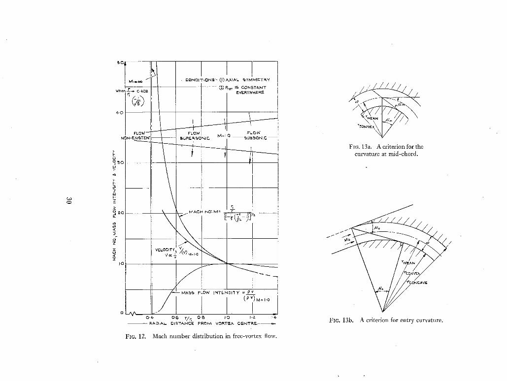
4-.c
U jo~.
~5
Z
I - Z
?: o~.
g3
.<
Z
32 U
I'
O,4-
- - R ~ , D I A L
o . 6 r / r ' g . ~ ~,o J , z ~'4-
DIS- I"A,N~.E F I ~ O M VGI~T~.X~ C~N~I 'R~-- - ~--
~~// FIG. 13a. Acriterion for the
curvature at mid-chord.
\ i
FIG. 13b. A criterion for entry curvature.
FIG. 12. Mach number distribution in free-vortex flow.
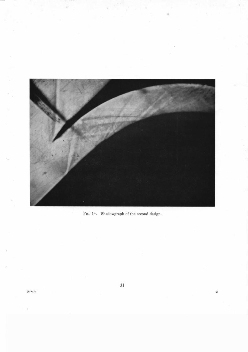
FIG. 14. Shadowgraph of the second design.
31
(,~ l~J4.'l) C

I i ! DECREASE IN AREA
CONTRACTION = INITIAL AREA
i I
40 39"97 AT ~
3 0
Z 0
~o
n.
7
8
I 0
O/ 1
/ /
S /
J /
j f f
FIG. 15.
2 3 4 MACH NUME~ER
Contraction allowable at a second throat when starting a one-dimensional wind tunnel.
32
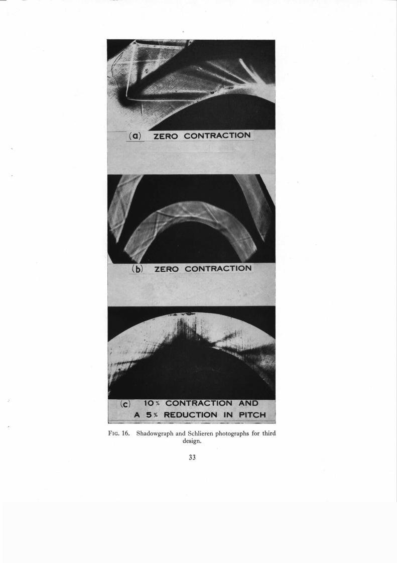
(0) Z E R O C O N T R A C T I O N
(b/ ZERO C O N T R A C T I O N
(C) 10% C O N T R A C T I O N
L--- . . . . A 5 ~_R_EDUCTION IN
A N D
PITCH
FIO. 16. Shadowgraph and Schlieren photographs for third design.
33
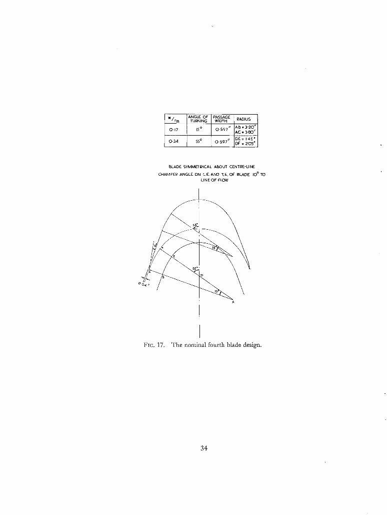
ANGLE OF PASSAGE RADIUS W/rm TURNING WIDTH
O.17 15 ° 0 .597" AI5 = 3"20" AC = 3.80"
0.34 55 o O.597r~ DE=I.45" DF = 205"
BLADE SYMMETRICAL AISOUT CENTRE-LINE
CHAMFEI~ ANGLE ON L.E. AND T.E. OF" BLADE IO°TO LINE OF FLOW
5 5 *
O. o
A
FIC. 17. The nominal fourth blade design.
34
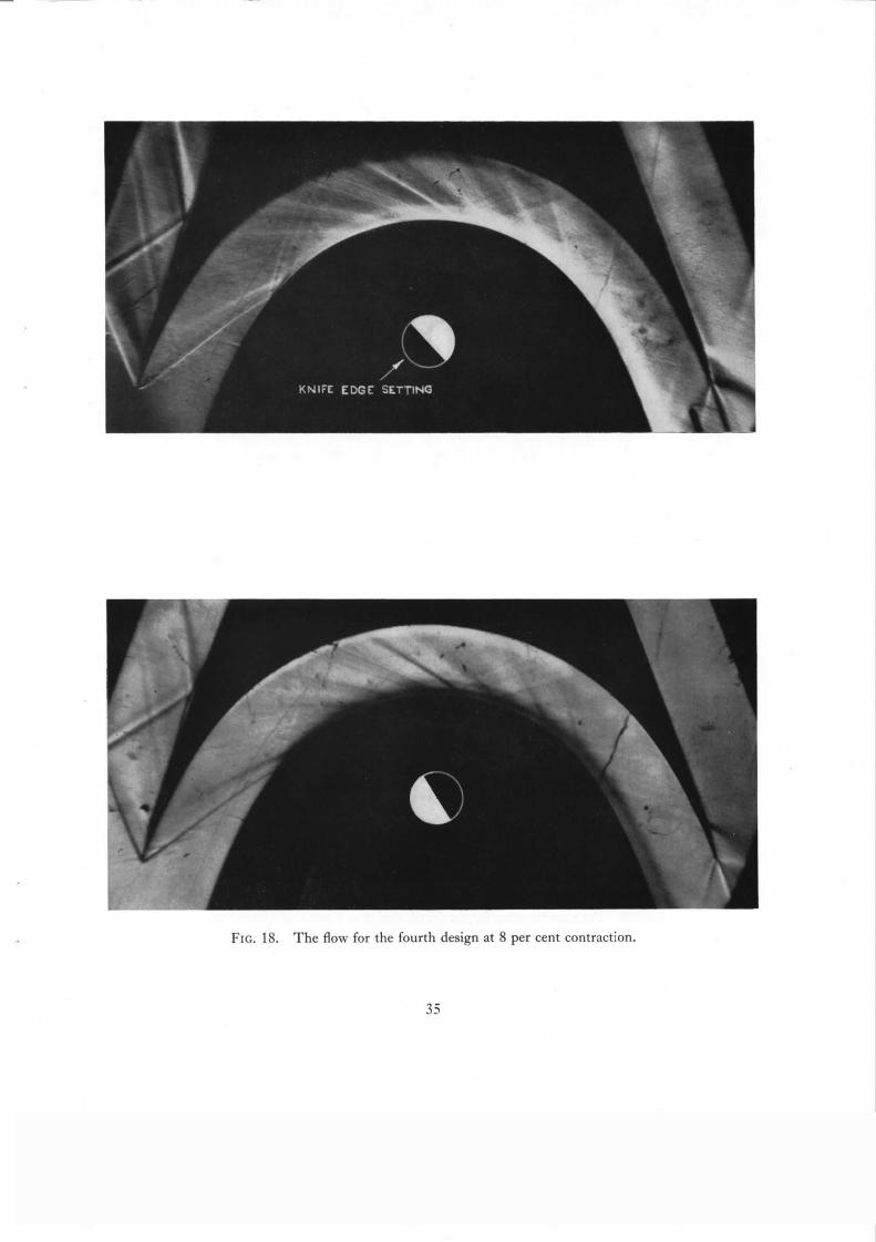
FIG. 18. The flow for the fourth design at 8 per cent contraction.
35

I '0
0 '8
u o o . s
u
0 P--
I ' 0
~.F'~"y~ q~TOT ,wL,TI
~ . s
/E~OOIT~ C ~ r F I C I ~ N " r
I ~ 0 " ~ 1 4 l , r
~s so 7s ~o0"] ,,-d /o
!TOT 0~,rLET ~ I
I
TOT INLET /
I ' O
0'~
I'- Z IJ 0 ,T O.S ILl 0 U
~t ur~ dl M
I P~T&TI C
O'P. C: . . . . - . . . . . . . . . . . . . O'~-
E/0CITY CO~FFICI[MT = 0 9'59
O I I I ^ ! O ?.5 50 7 ~ IO~ 70
P~RCr 'N~G r" OF PA~S~G~ Y'.J~TH ~RO~ INN~'R ~ L ~
P-O 5 ~ N TRAVERSE
~-o., -rOT 0UTL£~
PlTOT 0UTLJ" T
PTOT INL.F..T
2 PSTATIC
PTOT IM~E~ \
l
E L O C I ~ COEFFICIENT = 0 ' 9 5 ~
I I I Z5 SO 75 IOC
1'O
0 ' 8
I- z u
if_ IlL ILl O U
Ul
0 '~ .
/ 0 ~ L ~ T
/ P~T/kT[C
PTOT INl..r" "r
VCLOC[~ CO~F~ICIEN~ = 0 ' 9 5 7
I I I }/ Z5 50 ?5 10C /o
I ,O
0 " ~
I - Z IJ o ~. O.G
0 U
0'4- dl I11
O'P-
S°~ ~ A N T R a V E r S E
/ , "ro'r 0, m - E ~
P~OT INL~'T
V¢L0¢IT~ ¢OErr [CI~NT = 0 . S 8 4
I I I ~5 .50 75 10C
P E R C £ N T ~ £ O~ P ~ WIDTH F~OM IMMER WA~L
I-- Z W o ~_ 0 ' 6
8 IJ
3 0 . ¢ ILl
/'~ TOT 0U,-rLET
I o ~ ~ ~
P'r0T IN~.t" T
0 ' ~
%TA~'IC
P~OT IINI.. ~" T \
#~LOCf'YY C0~' F~'~I~N T --0 '98e,
I I I o/ /o ~ 5 5 O 7 5 I O 0
Fla. 19. Pressure traverses for the fourth design at 8 per cent contraction.
36
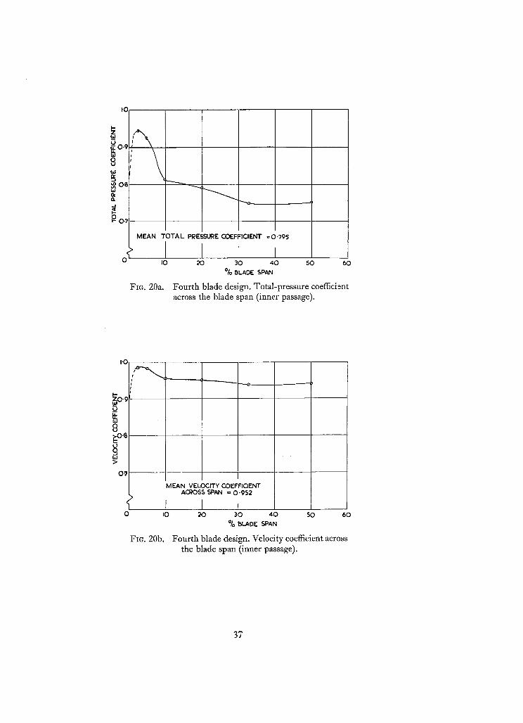
I'C
I- Z
8 w
f ~ ~L
MEAN TOTAL PRESSURE COEFFICIENT =0-795
I0
FIO. 20a.
20 30 40 50 60
% BLADE SPAN
Fourth blade design. Total-pressure coefficient across the blade span (inner passage).
I '0
I - ZO ' ;
IJJ
8 iC-o.s
hi >
0 ' 7
1 t
0 IO
FIc. 20b.
M EAN VELOCITY COEFFICIENT ACROSS SPAN ~ O'952
f I , 20 30 40 50 60
% ~.ADE SPAN
Fourth blade design. Velocity coefficient across the blade span (inner passage).
37

(o)
A N E A R L I E R B U I L D
(b)
C O N T R O L P H O T O G R A P H
(c)
U S I N G W E T AIR
(d)
U S I N G DRY AIR
m
T U N N E L V A L V E
P A R T I A L L Y C L O S E D
(f)
A SECOND TYPE OF
FLOW PATTERN
I
(g) T A P E ON C O N V E X S U R F A C E
FIG. 21. Additional photographs for the fourth design at 8 per cent contraction.
38
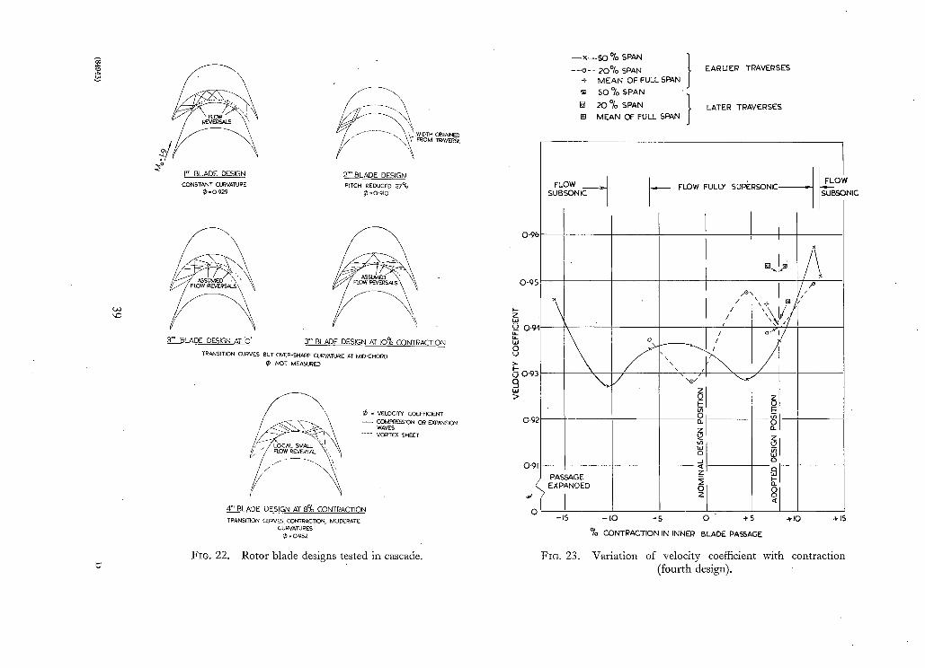
'4:)
I" BLADE DESIGN CONSTANT CUI~VATUI~ E
- o . 9 2 9
,WIDTH O6TAJ NED FROM ~AVERSE
2Z. ° BLADE DESIGN PITCH I~EDUGEO 27%
. o .gmo
3 ~ BLADE DESIGN AT 'O' 3 "° BLADE DESIGN AT E)% CONTRACTION
TRANSITION CUI?VES BUT OVER-SHARp CURVA]~JRE AT MID'CHORD NOT MEASURED
~) - VELOCITY COEFFICIENT - - ~PgESSION OR EXPANSION
WAVES .... VOI~TEX SHEET
4 ~ BLADE DESIGN AT 8% CONTPACTION TI?ANSmON CUI~VES, CONTRACTION MODCR)ATE
C U~tv'ATU ~ES 0 - o~;52
FIO. 22. Rotor blade designs tested in cascade.
O ' 9 6
0-95
i - z i.i O
O L)
O 0"93 9 >
- - × - - 5 0 % SPAN } - - e - - 2 0 % SPAN EARUER TRAVERSES
+ MEAN OF FULL SPAN
~1 50 % SPAN
[] 20 % SPAN ~, LATER TRAVERSES
J Et MEAN OF FULL SPAN
FLOW __~. SUBSONIC
\
FLOW FULLY SUPERSONIC -.
I
/
FLO~
SUBS(
/Q' \ 1 ~ /
/ F--
121
PASSAGE _z ,.# ~,/ EXPANDED {
o - 15 - IO -S O + S + 1 0 4-15
~o CONTRACTION IN INNER BLADE PASSAGE
FIO. 23. Variation of velocity coefficient with contraction (fourth design).

AIR
INLET
/
/ / / / /
NOZZLE
BLADE
/ / / / / / / / / / / / /
ROTOR BLADE
\
PERCENTAGE LAP = (,1~_ + b] x IOO% h
FIG. 24. A turbine annulus with lap.
(o)
PER BLO INSE
IN N
/ ,!
ILAI~'
FIG. 25.
(b) TUI~BINE LAP [See
LAP ~_---~- PEI~IPHERAL
f (c) TUNNEL LAP CONFIGURATIO_.NN
USED FOR 'PEPlPHEF~AI~
P LAP TEST QUOTED
IN TABLE F.~AL~ LAP PERIPH FOR OUTEI~ ~ , ~ /
/ Lap configurations in the tunnel and turbine.
40
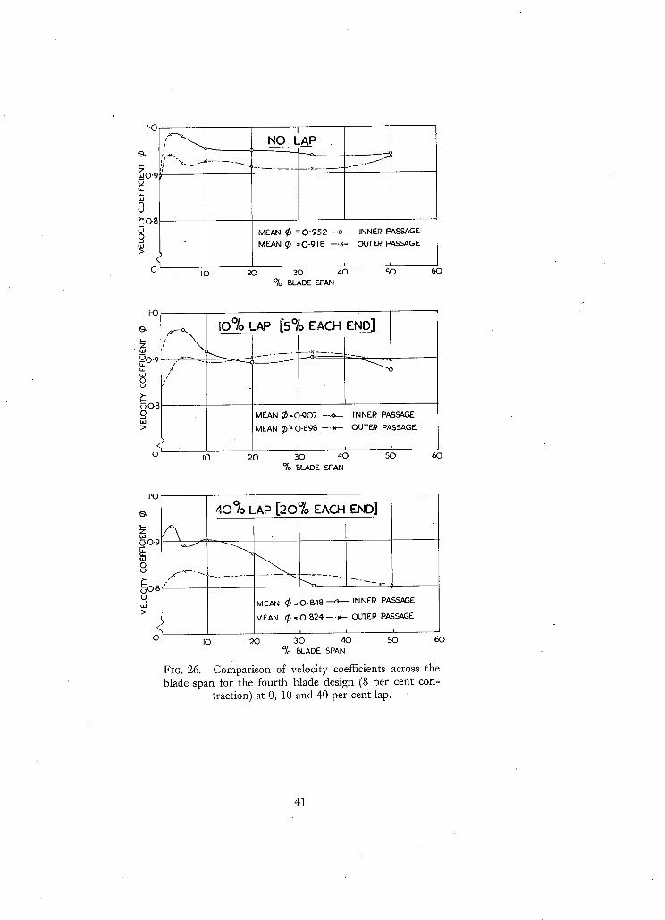
I.O
I- Zo.g
uJ
,9 ° ?:o8
9 tlJ >
'h O
if-w.. " ' x ~ . ,.~
I NO LAP
MEAN ~ = O'952 - -e - - INNER PASSAGE
MEAN ~) =O-91B ---~- OUTEI~ PASSAGE
i I0 20 30 4 0 5~3
% N_ADE SPAN 60
I'O
)--
,,-Uo.9 b- uJ o U
0(>8 g bd 2>
,> #
i0% LAP [5% EACH END]
x/ : ' ~ "
/ ¢
MEAN ~ = O ' 9 0 7 ~ INNER PASSAGE
MEAN ~)---O.898 - - . -K-~ OUTF_J2 PASSAGE.
I0 20 30 40 5(3 o~) ELADE SPAN
60
r o
40% LAP [20% EACH END]
U
~ O , B / " ~ ~ ' - -
O MEAN (X)=O.N8 + INNEI~ PASSAGE ~J >
MEAN (~ = O .B24 --.w--- OUTEP PASSAGE
i i i o IO 20 30 40 50 60
% ~I_ADE SPAN
FIG. 26. comparison of velocity coefficients across the blade span for the fourth blade design (8 per cent con-
traction) at 0, 10 and 40 per cent lap.
41
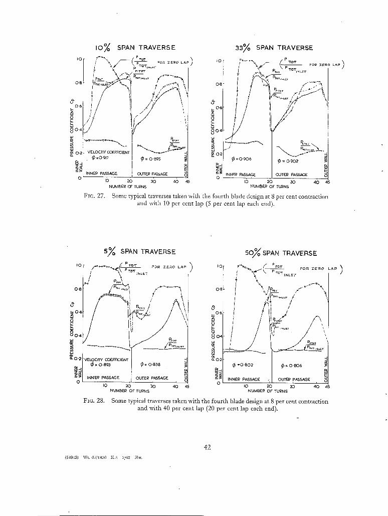
lOgo SPAN TRAVERSE
,.o[ F ' , ( ~'ro____Z_v .E~o ~ P ) / \ / ' - - - - ~p P.oT . . . . . ~o~
o.~ !~-7-,2,,~,~'~9~\.. T
"6
O2L VELOCIW COEFFICIENT .J
o ,b 26 36 ,6 45 NUM~SER Of" TUPNS
FIG. 27.
33% SPAN TRAVERSE
, \ / - 2 - . , , .) J - P,o-. ~'h.L.T
) ~ " .0.-~'-7a, oB ! ,~ i ,~ P. .... J----L--J,
1 k.,o . . . . . . G.--"- ~o,~ j/ ~/ e~ 0 = ome
uJj~z ~e NNF-J? PASSAGI'2 OUTEI~ PASS.a~GE O u
NUMBEI? OF TURNS
Some typical traverses taken with the fourth blade design at 8 per cent contraction and with 10 per cent lap (5 per cent lap each end).
I'0
O'B
0
0.t
u
8 0'~ tlJ o¢
o. 0"2
0
5~o SPAN TRAVERSE
/ P TOT jNLET
t \
r
R ' f S \ - - / j
"VELOEITf COEEEIENT (~ = O.B93 (~ = 0.838
INNER PASSAGE OUTER PASSAGE
I0 20 30 4O 45 NUMBER OF TURNS
F i o . 2 8 .
5Oy SPAN TRAVERSE
[ '0 [ PT~T FO.~ ZEl~O L A ~ "~ P YO~"
INLET
0 "- ( ~ . . . . /
/ ?
4 I 0 6 , . /
I - -
iG . . . . . . / , I Xj '
0.2
=o.~o2 ~ = o.8o~
7Z~ INNEI? PASSAGE OUTE~ PASSAGE
20 30 40 4S NUMBER OF TURNS
Some typical traverses taken with the fourth blade design at 8 per cent contraction and with 40 per cent lap (20 per cent lap each end).
(84943) Wt. 67/1876 I':.5 7/62 Hw.
42
Publications of the Aeronautical Research Council
A N N U A L TECHNICAL REPORTS OF THE AERONAUTICAL RESEARCH COUNCIL (BOUND VOLUMES)
x942 Vol. I. Aero and Hydrodynamics, Aerofoils, Airscrews, Engines. 75s. (post 2s. 9d.) Vol. II. Noise, Parachutes, Stability and Control, Structures, Vibration, Wind Tunnels. 47s. 6d. (post as. 3d.)
x943 Vol. I. Aerodynamics, Aerofoils, Airscrews. 8os. (post as. 6d.) VoL II. Engines, Flutter, Materials, Parachutes, Performance, Stability and Control, Structures.
/ 9os. (post as. 9d.) x944 VoL I. Aero and Hydrodynamics, Aerofoils, Aircraft, Airscrews, Controls. 84s. (post 3s.)
Vol. II. Flutter and Vibration, Materials, Miscellaneous, Navigation, Parachutes, Performance, Plates and Panels, Stability, Structures, Test Equipment, Wind Tunnels. 84s. (post 3s.)
x945 Vol. I. Aero and Hydrodynamics, Aerofoils, x3os. (post 3s. 6d.) Vol. II. Aircraft, Airscrews, Controls. I3OS. (post 3s. 6d.) Vol. III. Flutter and Vibration, Instruments, Miscellaneous, Parachutes, Plates and Panels, Propulsion.
z3os. (post 3s. 30?.) Vol. IV. Stability, Structures, Wind Tunnels, Wind Tunnel Technique. I3OS. (post 3s. 3d.)
1946 Vol. I. Accidents, Aerodynamics, Aerofoils and:Hydrofoils, i68s. (post 3s. 9d.) Vol. II. Airscrews, Cabin Cooling, Chemical Hazards, Controls, Flames~ Flutter, Helicopters, Instruments and
Instrumentation, Interference, Jets, Miscellaneous, Parachutes. I68S. (post 3s. 3d.) VoL III. Performance, Propulsion, Seaplanes, Stability, Structures, Wind Tunnels. i68s. (post 3s. 6d.)
x947 Vol. I. Aerodynamics, Aerofoils, Aircraft. I68S. (post 3s. 9d.) Vol. II. Airscrews and Rotors, Controls, Flutter, Materials, Miscellaneous, Parachutes, Propulsion, Seaplanes,
Stability, Structures, Take-off and Landing. i68s. (post 3s. 9d.)
I948 Vol. I. Aerodynamics, Aerofoils, Aircraft, Airscrewsl Controls, Flutter and Vibration, Helicopters, Instruments, Propulsion, Seaplane, Stability, Structures, Wind Tunnels. z3os. (post 3s. 3d.)
Vol. II. Aerodynamics, Aerofoils, Aircraft, Airscrews, Controls, Flutter and Vibration, Helicopters, Instruments, Propulsion, Seaplane, Stability, Structures, Wind Tunnels. Ilos. (post 3s. 3d.)
Special Volumes Vol. I. Aero and Hydrodynamics, Aerofoils, Controls, Flutter, Kites, Parachutes, Performance, Propulsion,
Stability. i26s. (post 3s.) Vol. II. Aero and Hydrodynamics, Aerofoils, Airscrews, Controls, Flutter, Materials, Miscellaneous, Parachutes,
- Propulsion, Stability, Structures. I47s. (post 3s.) Vol. III. Aer~ and Hydrodynamics, Aerofoils, Airscrews, Controls, Flutter, Kites, Miscellaneous, Parachutes,
Propulsion, Seaplanes, Stability, Structures, Test Equipment. i89s. (post 3s. 9d.)
Reviews of the Aeronautical Research Council I939-48 3s- (post 6d.) I949-54 5s- (post 5d.)
Index to all Reports and Memoranda published in the Annual Technical Reports I909-I947 R. & M. 2600 (out of print)
Indexes to the Reports and Memoranda of the Aeronautical Research Council
H E R
Between Nos. 2351-2449 R. • M. No. 2450 Between Nos. 2451-2549 R. & M. No. 2550 Between Nos. 2551-2649 R. & M. No. 2650 Between Nos. 265I-Z749 R. & M. No. 275 ° Between Nos. 2751-2849 R. & M. No. 285o Between Nos. 2851-2949 R. & M. No. 295 ° Between Nos. 2951-3o49 R. & M. No. 3o5o Between Nos. 3o5i-3x49 R. & M. No. 315o
MAJESTY'S S T A T I O N f rom the addresses overleaf
as. (post 3d.) as. 6d. (post 3(/.) as. 6d. (post 3d.) as. 6d. (post 3d.) 2s. 6d. (post 3d.) 3s. (post 3d.) 3s. 6d. (post 3d.) 3s. 6d. (post 3d.)
ERY O F F I C E

R. & M. No . 3275
© Crown copyright I962
Printed and published by HER MAJESTY'S STATIONERY OFFICE
To be purchased from York House, Kingsway, London w.c.2
423 Oxford Street, London w. i X3A Castle Street, Edinburgh 2
lO9 St. Mary Street, Cardiff 39 King Street, Manchester z
5o Fairfax Street, Bristol x 35 Smallbrook, Ringway, Birmingham 5
8o Chlchester Street, Belfast I or through any bookseller
Printed in England
~, & Mo No° 3275
S.O. Code No. 23-3275