theory report major
TRANSCRIPT

Page | 9
Chapter 1
Introduction
1.1 Overview
Filters are frequency selective devices. Filters are often used in electronic systems to
emphasize signals in certain frequency ranges and reject signals in other frequency ranges.
In circuit theory, a filter is an electrical network that alters the amplitude and/or phase
characteristics of a signal with respect to frequency. Ideally, a filter will not add new
frequencies to the input signal, nor will it change the component frequencies of that signal,
but it will change the relative amplitudes of the various frequency components and/or their
phase relationships. Filters are often used in electronic systems to emphasize signals in
certain frequency ranges and reject signals in other frequency ranges. Such a filter has a
gain which is dependent on signal frequency.The frequency-domain behaviour of a filter is
described mathematically in terms of its transfer function which is the ratio of the Laplace
transform of its output to Laplace transform of input signals. Knowing the transfer function
magnitude at each frequency allows us to determine how well the filter can distinguish
between signals at different frequencies. The transfer function magnitude versus frequency
is called the amplitude response or the frequency response.
Microwave Filters are two-port networks used to control the frequency response in an RF
or Microwave system. They allow transmission of signal frequencies within their pass-
band, and attenuate signals outside their pass-band. Common RF and Microwave filter
types are listed below:
Transmission line stubs filters. These filters are implemented using
transmission lines in place of lumped elements.
Comb-Line filters. Quarter-wave transmission line resonators are used in the
design of comb-line filters. Quarter-wave transmission lines are capacitively
coupled.
Waveguide discontinuity filters. The low loss and high power handling
characteristics of waveguides lend themselves to the use of waveguides in
specialized filters.
Page | 10
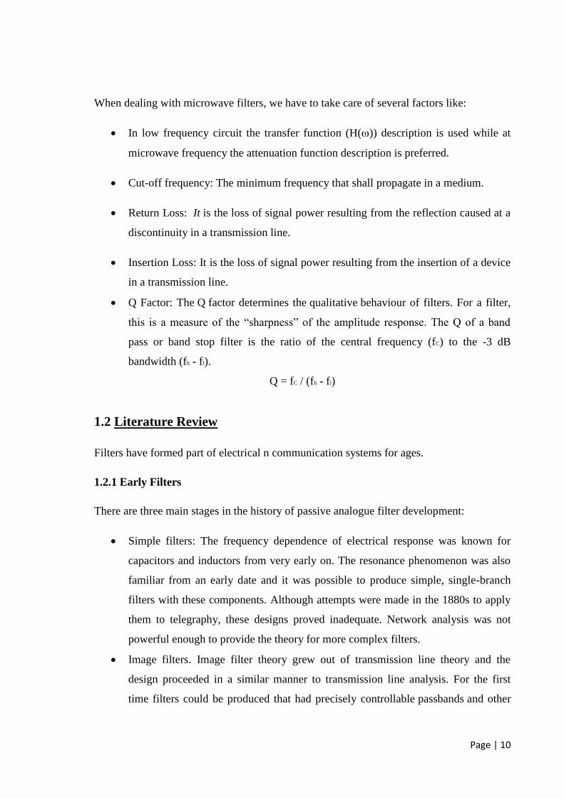
When dealing with microwave filters, we have to take care of several factors like:
In low frequency circuit the transfer function (H()) description is used while at
microwave frequency the attenuation function description is preferred.
Cut-off frequency: The minimum frequency that shall propagate in a medium.
Return Loss: It is the loss of signal power resulting from the reflection caused at a
discontinuity in a transmission line.
Insertion Loss: It is the loss of signal power resulting from the insertion of a device
in a transmission line.
Q Factor: The Q factor determines the qualitative behaviour of filters. For a filter,
this is a measure of the “sharpness” of the amplitude response. The Q of a band
pass or band stop filter is the ratio of the central frequency (fC) to the -3 dB
bandwidth (fh - fl).
Q = fC / (fh - fl)
1.2 Literature Review
Filters have formed part of electrical n communication systems for ages.
1.2.1 Early Filters
There are three main stages in the history of passive analogue filter development:
Simple filters: The frequency dependence of electrical response was known for
capacitors and inductors from very early on. The resonance phenomenon was also
familiar from an early date and it was possible to produce simple, single-branch
filters with these components. Although attempts were made in the 1880s to apply
them to telegraphy, these designs proved inadequate. Network analysis was not
powerful enough to provide the theory for more complex filters.
Image filters. Image filter theory grew out of transmission line theory and the
design proceeded in a similar manner to transmission line analysis. For the first
time filters could be produced that had precisely controllable passbands and other

Page | 11
parameters. Their immediate application was the development of frequency
division multiplexing for use on intercity and international telephony lines.
Network synthesis filters. The mathematical bases of network synthesis were laid in
the 1930s and 1940s. Network synthesis put filter design on a firm mathematical
foundation, freeing it from the mathematically sloppy techniques of image design
and severing the connection with physical lines. The essence of network synthesis
is that it produces a design that will (at least if implemented with ideal components)
accurately reproduce the response.
Early filters made use of resonance for filtering purpose. This was achievable by use of
simple Resistors, Inductors and Capacitors. Sophistication of filter required filter that has a
flat frequency response in the required passband like a low-Q resonant circuit, but that
rapidly falls in response at the transition from passband to stopband like a high-Q resonant
circuit. To accommodate two contradictory requirements on a single resonating circuit was
a challenging problem.
The solution to these needs was founded in the theory of transmission lines and
consequently the necessary filters did not become available until this theory was fully
developed. At this early stage the idea of signal bandwidth, and hence the need for filters to
match to it, was not fully understood. Indeed, it was as late as 1920 before the concept of
bandwidth was fully established. For early radio, the concepts of Q-factor, selectivity and
tuning sufficed. This was all to change with the developing theory of transmission lines.
1.2.2 Transmission Line as Filters
The earliest model of the transmission line was probably described by Georg Ohm (1827)
who established that resistance in a wire is proportional to its length. The Ohm model thus
included only resistance. Latimer Clark noted that signals were delayed and elongated
along a cable, an undesirable form of distortion and Michael Faraday (1853) established
that this was due to the capacitance present in the transmission line. The mathematical
model of the transmission line reached its fullest development with Oliver Heaviside.
Heaviside introduced series inductance and shunt conductance into the model making
four distributed elements in all. This model is now known as the telegrapher's equation and
the distributed elements are called the primary line constants.

Page | 12
1.3 Objective
This project presents a new type of compact notch filter. The proposed filter topology
consists of double spurlines and double open circuited stubs. Double spurlines are
introduced to a conventional open stub filter for filter circuit size miniaturization and
bandstop region improvement. It is clearly shown that the rejection region of the proposed
filter is wider and deeper compared to the conventional open stub filter without any
cascading circuits or periodic structures. To validate the proposed topology, a compact
filter prototype with bandstop centered at 3.5 GHz is simulated and transmission
coefficient measurements are noted.
Measurements show that there is a rejection region from 2.5 to 4.5 GHz with insertion loss
(S21) less than -15dB . The total length of the prototype equals to 45 mm.
1.4 Software Used
High Frequency Structure Simulator (HFSS)
The name HFSS stands for High Frequency Structure Simulator. Ansoft pioneered the use
of the Finite Element Method (FEM) for EM simulation. Today, HFSS continues to lead
the industry with innovations. HFSS is a software package for electromagnetic modelling
and analysis of passive, three-dimensional structures. It helps the user to observe and
analyze various electromagnetic properties of the structure.
HFSS is a high performance full wave electromagnetic (EM) field simulator for arbitrary
3D volumetric passive device modeling that takes advantage of the familiar Microsoft
Windows graphical user interface. It integrates simulation, visualization and solid
modelling, in an easy to learn environment where solutions to your 3D EM problems are
quickly and accurately obtained.
Ansoft HFSS has evolved over a period of years with input from many users and
industries. In industry, Ansoft HFSS is the tool of choice for High productivity research
and development. The Ansoft HFSS 3D Modeler is designed for ease of use and flexibility.
The power of the 3D Modeler is in its unique ability to create fully parametric designs
without editing complex macros/model history.

Page | 13
Chapter 2
Microwave Filters
2.1 Introduction
Since years, filters have formed an essential part of electronics industry and will continue
to play an important role in this sector for years to come. Filters, as the name suggests, are
hardware, which work on basic principle of filtering. Filtering is a process wherein one
separates desired entities from undesired ones.
Following are the types of filters that we are familiar with:
2.1.1 Low Pass Filter
A low-pass filter passes low frequency signals, and rejects signals at frequencies above the
filter's cutoff frequency. Low pass filters are also known as integrators. By inspection of
the amplitude response of a low pass filter, we can say that the filter possesses high gain at
low frequencies and low gain at high frequencies. These filters are employed when we
don’t want the high frequency signals to corrupt the low frequency message signals. For
example in case of our home appliances used on 50 Hz transmission line we can reject
frequencies greater than 50 Hz to protect them from getting damaged.
2.1.2 High Pass Filter
A high-pass filter blocks low frequency signals and passes signals at frequencies above the
filter’s cutoff frequency. High pass filters are also known as differentiators.
By inspection of the amplitude response of a high pass filter, we can say that the filter
possesses high gain at high frequencies and low gain at low frequencies. These filters are
employed when we don’t want the low frequency signals to corrupt the high frequency
message signals.

Page | 14
A useful application of high pass filters is in the high fidelity (Hi-Fi) systems. Music
contains significant energy in the frequency range from around 100 Hz to 2 kHz, but high-
frequency drivers (tweeters) can be damaged if low-frequency audio signals of sufficient
energy appear at their input terminals.
A high-pass filter between the broadband audio signal and the tweeter input terminals will
prevent low-frequency program material from reaching the tweeter. In conjunction with a
low-pass filter for the low-frequency driver (and possibly other filters for other drivers),
the high-pass filter is part of what is known as a ``crossover network''.
2.1.3 Band Pass Filter
A band-pass filter allows only certain desired band of frequencies to pass through it while
rejecting the other undesired ones. By inspection of the amplitude response of ideal band
pass filters, we notice that they have constant gain in pass band and zero gain outside the
pass band and an abrupt boundary between the two. Stopband is the range of frequencies
where unwanted signals are attenuated. A band pass filter has two such stopbands, one
each above and below the pass band. Classic example of bandstop filters are the FM
receivers where frequencies in the band 88-108 Mhz are needed and rest are rejected.
2.1.4 Notch Filter
A notch filter allows all frequencies to pass through it while rejecting a particular band of
undesired frequencies. By inspection of amplitude response of ideal notch filters, we notice
that they have zero gain in stop band and constant gain outside stopband and an abrupt
boundary between the two. A notch filter has two passbands, one each below and above
the stop band. An example of the use of a notch filter is with an audio program that has
been contaminated by 60 Hz powerline hum. A notch filter with a central frequency of 60
Hz can remove the hum while having little effect on the audio signals.

Page | 15
2.2 Notch filters
Notch filters are used to remove an unwanted frequency from a signal, while affecting all
other frequencies as little as possible. The frequency response of an ideal notch filter is as
shown:
Fig 1.Frequency Domain Characteristics of an Ideal Notch Filter
Page | 16
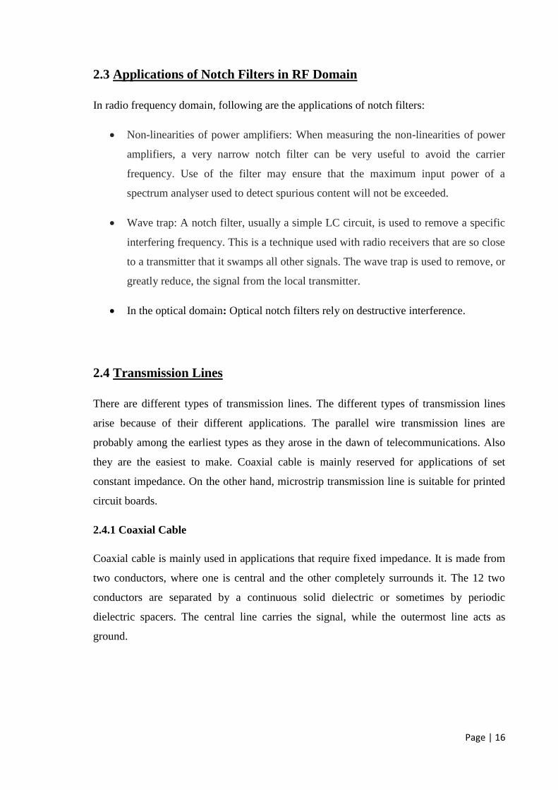
2.3 Applications of Notch Filters in RF Domain
In radio frequency domain, following are the applications of notch filters:
Non-linearities of power amplifiers: When measuring the non-linearities of power
amplifiers, a very narrow notch filter can be very useful to avoid the carrier
frequency. Use of the filter may ensure that the maximum input power of a
spectrum analyser used to detect spurious content will not be exceeded.
Wave trap: A notch filter, usually a simple LC circuit, is used to remove a specific
interfering frequency. This is a technique used with radio receivers that are so close
to a transmitter that it swamps all other signals. The wave trap is used to remove, or
greatly reduce, the signal from the local transmitter.
In the optical domain: Optical notch filters rely on destructive interference.
2.4 Transmission Lines
There are different types of transmission lines. The different types of transmission lines
arise because of their different applications. The parallel wire transmission lines are
probably among the earliest types as they arose in the dawn of telecommunications. Also
they are the easiest to make. Coaxial cable is mainly reserved for applications of set
constant impedance. On the other hand, microstrip transmission line is suitable for printed
circuit boards.
2.4.1 Coaxial Cable
Coaxial cable is mainly used in applications that require fixed impedance. It is made from
two conductors, where one is central and the other completely surrounds it. The 12 two
conductors are separated by a continuous solid dielectric or sometimes by periodic
dielectric spacers. The central line carries the signal, while the outermost line acts as
ground.

Page | 17
2.4.2 Open-Wire Lines
Open-wire lines are made out of copper wire and non-conducting spacers. The open-wire
lines do have the disadvantage that they must be kept away from other conductors and
earthed objects. Also as frequency increases the open-wire line spacing becomes a
significant fraction of the wavelength and the line will radiate.
2.4.3 Microstrip
Microstrip transmission line consists of a track of copper or other conductor on an
insulating structure. There is a sheet of the similar conductor on the other side of the
insulator. The track of copper acts as a passage of the signal while the sheet on the other
side provides a return path; therefore microstrip is a variant of two-wire transmission line.
Microstrip is predominantly used in printed circuit boards.
2.5 Stubs
In microwave and radio-frequency engineering, a stub is a length of transmission
line or waveguide that is connected at one end only. The free end of the stub is either left
open-circuit or (especially in the case of waveguides) short-circuited. Neglecting
transmission line losses, the input impedance of the stub is purely reactive;
either capacitive or inductive, depending on the electrical length of the stub, and on
whether it is open or short circuit. Stubs may thus be considered to be frequency-dependent
capacitors and frequency-dependent inductors.
Since stubs take on reactive properties as a function of their electrical length, stubs are
most common in microwave circuits where the line lengths are more manageable. Stubs
are commonly used in frequency selective filters.
Page | 18
2.6 Meander Spurline
The conventional method to implement notch filters involves the use of shunt stubs or
stepped-impedance microstrip lines with large circuit size. These exhibit exhibit good
bandstop characteristics and are popularly applied in notch filter designs. However, their
stopband bandwidth and sharp cutoff frequency response are enhanced by four or more
cells, which lead to larger size and more transmission loss in the stopband.
The meander spurline enhances the Q value of the resonator which implies that it allows
filter to achieve low noise notch characteristics. A compact meander spurline with low
resonant frequency and improved slow-wave factor is proposed and analyzed. In a notch
filter using a meander structure. The top layer is the microstrip with a spurline, the middle
layer is the substrate, and the bottom layer is the ground plane. Actually, the idea to
implement a notch filter through meander spurlines is to provide a lower resonant
frequency and an improved slow-wave factor which makes size-reduction possible.

Page | 19
CHAPTER 3
Filter Design Techniques
3.1 Introduction
Since several decades ago, both active and passive filters are widely used to suppress
unwanted signals. At microwave frequencies, passive components like transmission lines
have been used for designing passive filters oriented to wireless communications
applications, where open, short stubs, and coupled lined are some common proposals.
With rapid development in modern communication technology, there has been a growing
interest in microwave devices for communication applications. The microstrip filter is an
example of a microwave device which is widely used in modern communication systems.
In the research community, microstrip filters of various responses are highly employed,
e.g., lowpass, highpass, bandpass and bandstop filters. In addition, microstrip notch filter
with harmonic suppression using compact and double spurlines has been discussed.
Firstly, Modern communication systems often require low cost and compact size devices.
Research trends in modern communication systems, therefore, tend to implement low cost,
compact size, and simple fabrication for modern communication devices. Notch filters are
important devices in rejecting higher harmonics and spurious response for microwave,
millimetre wave, and Terahertz applications. The conventional technique to implement
notch filters involves the use of stepped impedance microstrip lines and open stubs that
increase the circuit size.
3.2 Realization of Microwave Filters
At frequency below 1.0GHz, filters are usually implemented using lumped elements such
as resistors, inductors and capacitors. For active filters, operational amplifier is sometimes
used. The ideal filter would have zero insertion loss in the passband, infinite attenuation in
the stop, and a linear phase response(to avoid signal distortion) in the passband, Of course,
such filters do not exist in practice, so compromises must be made; herein lies the art of
filter design.
Page | 20
There are essentially two low-frequency filter syntheses techniques in common use. These
are referred to as the
Image Parameter Method (IPM)
Insertion Loss Method (ILM)
3.2.1 Filter Design by Image Parameter Method (IPM)
This method provides a filter having desired passband and stopband characteristics. The
relation between the image parameters and the general circuit parameters, for example
open-circuit and short-circuit impedances, is that transmission properties of general circuits
can be defined in terms of their image parameters. The IPM approach divides a filter into a
cascade of two-port networks, and attempt to come up with the schematic of each two-port,
such that when combined, give the required frequency response.
The image method of filter design determines the properties of filter sections by
calculating the properties they have in an infinite chain of such sections. In this, the
analysis parallels transmission line theory on which it is based. Filters designed by this
method are called image parameter filters, or just image filters. An important parameter of
image filters is their image impedance, the impedance of an infinite chain of identical
sections.
The basic sections are arranged into a ladder network of several sections, the number of
sections required is mostly determined by the amount of stopband rejection required. In its
simplest form, the filter can consist entirely of identical sections. The most frequent
parameters considered are stopband rejection, steepness of the filter skirt (transition band)
and impedance matching to the filter terminations. Image filters are linear filters and are
invariably also passive in implementation.
Disadvantages of Image Parameter Method
If the filter designed by Image Parameter Method does not meet the desired
characteristics of filter, then there is no simple way to improve the design.
Successful designing of filter is not guaranteed as it requires lot of hit and trial to
accurately define band edges.

Page | 21
3.2.2 Filter design by Insertion Loss Method (ILM)
This is a network synthesis method. The modern filter theory was developed by Darlington
and subsequently improved by Mathaei. Insertion loss results from the insertion of a device
in a transmission line. It is expressed as the reciprocal of the ratio of the signal power
delivered to that part of the line following the device to the signal power delivered to that
same part before inserting the device. Insertion loss method applies to the design of low-
pass, high-pass, band-pass and notch filters. There are trade-offs between insertion loss and
sharp cut-off to achieve accurate results. The insertion-loss method begins with a complete
specification of a physically realizable frequency characteristic, and from this a suitable
filter schematic is synthesized. Insertion loss filter design method allows for two degrees of
freedom when implementing filters using transmission lines. The degrees of freedom are
the length of the transmission line and its characteristic impedance.
21
1
load todeliveredPower
source thefrom availablePower
load
incIL
P
PP
The insertion loss method allows a high degree of control over the passband and stopband
amplitude and phase characteristics, with a systematic way to synthesize a desired
response. The necessary design trade-offs can be evaluated to best meet the application
requirements.
3.2.3 Advantages of Insertion Loss Method over Image Parameter Method
More reliable design technique as compared to Image Parameter Method as it
provides a systematic approach rather than a hit and trial one.
Better results can be obtained which can be easily improved by modifying the
design.
In large frequency filter design process we cant let errors creep into the design so
we have no option but to use this approach as it provides minimum chance of error.

Page | 22
3.3 Spurline Notch Filters
3.3.1 Single Spurline Notch Filter
Notch filters that are workable in radio frequency domain are worked out by using
spurlines. The filter consists of a normal microstrip line breaking into a pair of smaller
coupled lines that re-join after a quarter-wavelength distance. Among microstrip filter
designs, spurline is a simple defected microstrip structure and is the smallest structure
compared to other filter designs. The notch frequency of an individual spurline structure
could be tuned by optimizing just three basic parameters:
length (a)
height (b)
internal gap (s).
Normally, the slot gap exhibits a capacitive effect while the narrow microstrip line
provides an inductive effect. For a spurline filter the length and height dictate frequency of
notch characteristics which means that we can improve the notch characteristics by varying
the length and height parameters. In a way we can say that these act as characteristics
governing parameters. Bandwidth is governed by the gap. Sometimes there may be
requirements where one would need to alter the region of operation or the bandwidth of the
notch filter. In these cases we tend to parameterize the gap and adjust it according to the
bandwidth requirements. The frequency response at which notch occurs increases as length
decreases.
Fig 2.Illustrative Single Spurline Filter

Page | 23
3.3.2 Double Spurline Notch Filter
The illustrative figure of double spurline is as shown below:
To improve the bandstop region for the filter proposed by spurline structure, the effects of
double spurlines on transmission coefficients are examined to compare with that of single
spurline. The rejected frequency of a single spurline is based on the inductance value and
capacitance value which are in parallel. Their product is LC which is inversely
proportional to the rejected frequency.
When two single spurlines are parallel as the double spurlines, the inductance value
becomes 0.5 L and the capacitance value becomes 2 C. Consequently, their product is still
LC. This confirms that the rejected frequency by double spurline structure is equal to the
rejected frequency by single spurline.
The rejection bandwidth of double spurlines is very wide compared to that of single
spurline. Also the rejection level of double spurlines is very deep compared to that of
single spurline. With the compact circuit size of double spurlines, it is very suitable to
apply double spurlines as a compact bandstop filter.
Fig 3.Illustrative Double Spurline Filter
Page | 24
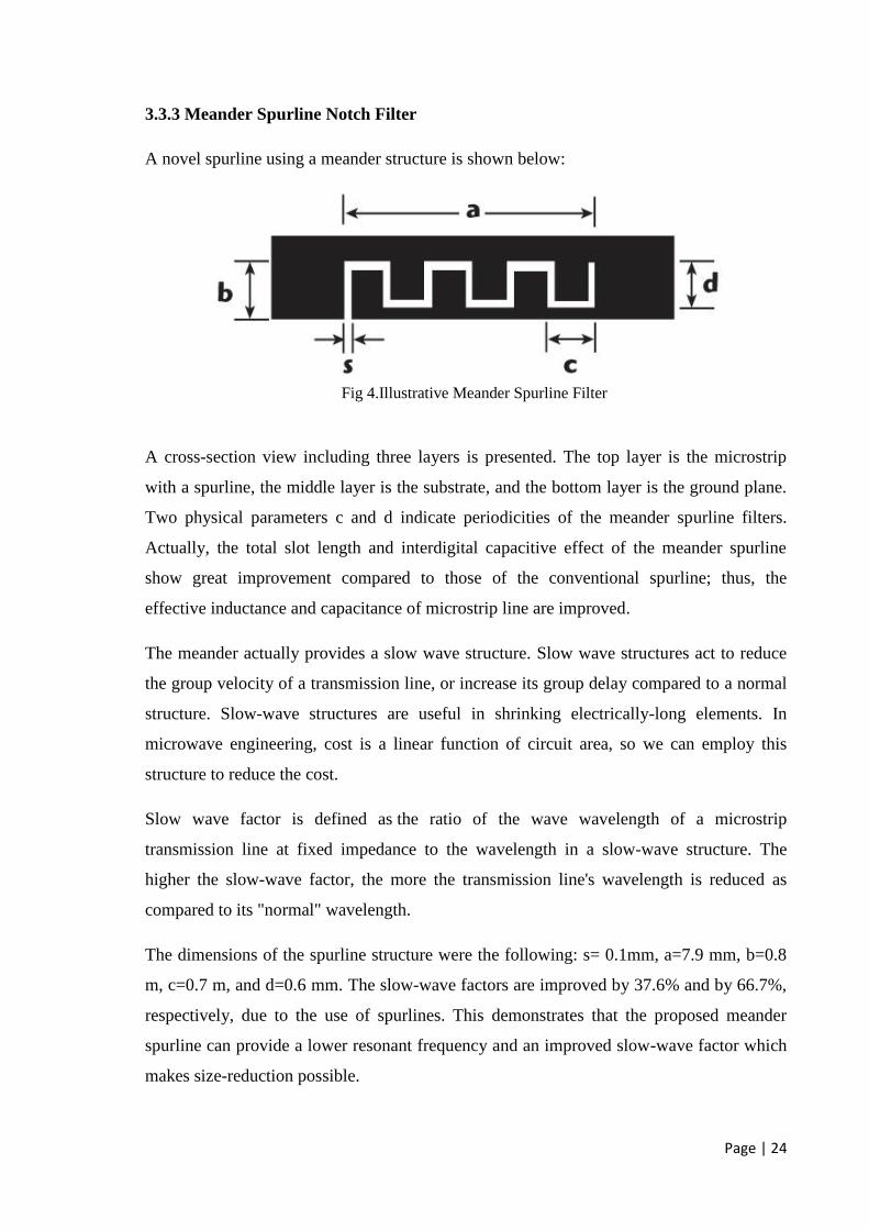
3.3.3 Meander Spurline Notch Filter
A novel spurline using a meander structure is shown below:
A cross-section view including three layers is presented. The top layer is the microstrip
with a spurline, the middle layer is the substrate, and the bottom layer is the ground plane.
Two physical parameters c and d indicate periodicities of the meander spurline filters.
Actually, the total slot length and interdigital capacitive effect of the meander spurline
show great improvement compared to those of the conventional spurline; thus, the
effective inductance and capacitance of microstrip line are improved.
The meander actually provides a slow wave structure. Slow wave structures act to reduce
the group velocity of a transmission line, or increase its group delay compared to a normal
structure. Slow-wave structures are useful in shrinking electrically-long elements. In
microwave engineering, cost is a linear function of circuit area, so we can employ this
structure to reduce the cost.
Slow wave factor is defined as the ratio of the wave wavelength of a microstrip
transmission line at fixed impedance to the wavelength in a slow-wave structure. The
higher the slow-wave factor, the more the transmission line's wavelength is reduced as
compared to its "normal" wavelength.
The dimensions of the spurline structure were the following: s= 0.1mm, a=7.9 mm, b=0.8
m, c=0.7 m, and d=0.6 mm. The slow-wave factors are improved by 37.6% and by 66.7%,
respectively, due to the use of spurlines. This demonstrates that the proposed meander
spurline can provide a lower resonant frequency and an improved slow-wave factor which
makes size-reduction possible.
Fig 4.Illustrative Meander Spurline Filter

Page | 25
3.3.4 Advantages of using Spurline Notch Filters
The use of spurline while designing notch filters has many advantages, of which, a few
have been listed as below:
It radiates lesser power than the conventional filters employing lumped elements.
It forms compact structure and hence is easily portable.
Its frequency response repeats at almost exact odd multiples of frequency which
marks its non dispersive nature.
Less susceptible to the influence of other components and lines in its vicinity.
Almost ideal characteristics like constant gain in pass band and zero gain in stop
band.
It possesses high insertion loss.

Page | 26
3.4 Open Stub Notch Filters
3.4.1 Single Open Circuited Stub Notch Filter
Stubs are a length of transmission line connected at one end only with other end open are
called open-circuited stub filters or open stub filters. Reactive properties of stubs are
function of their lengths. That is we need to parameterize the stub’s length as per our
requirements of a capacitive or an inductive element.
Basically, an open stub filter is a conventional filter, which is highly used. Open-wire
parallel lines can be used to implement transmission line filters. Transmission line filters
have stubs that are either open-circuited or short stub filters.
Open circuited stubs filters make use of 900
bending property of microstrip line according
to which two stubs if are placed perpendicular to each other in form of orthogonal
microstrip lines then each of the microstrip line represents a separate element like
capacitor, inductor and resistance. This property helps us in preserving the conventional
core of the notch filters which required the use of traditional elements inductor and
capacitor.
3.4.2 Double Open Circuit Stub Notch Filter
By cascading more open stubs of an open stub filter, a wider rejection bandwidth and a
deeper rejection can be obtained at the expense of increasing the insertion loss in the
passband and the overall circuit size.
Fig 5.Illustrative Open Circuited Stub Filter
Page | 27
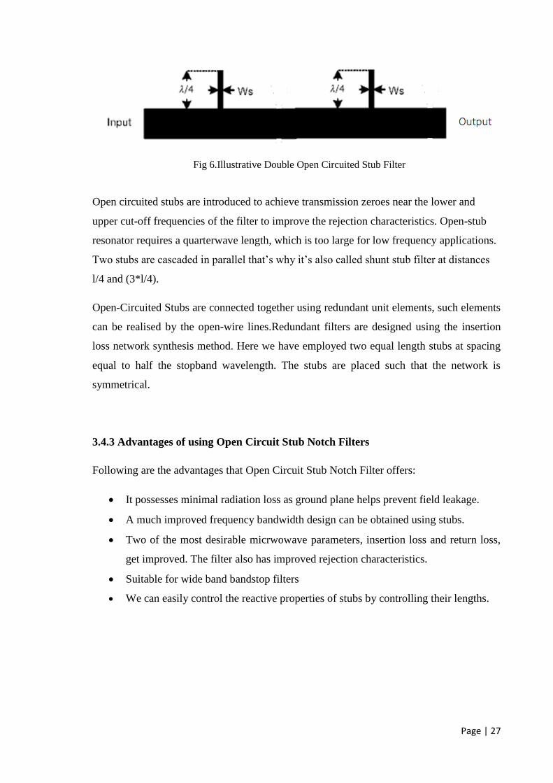
Open circuited stubs are introduced to achieve transmission zeroes near the lower and
upper cut-off frequencies of the filter to improve the rejection characteristics. Open-stub
resonator requires a quarterwave length, which is too large for low frequency applications.
Two stubs are cascaded in parallel that’s why it’s also called shunt stub filter at distances
l/4 and (3*l/4).
Open-Circuited Stubs are connected together using redundant unit elements, such elements
can be realised by the open-wire lines.Redundant filters are designed using the insertion
loss network synthesis method. Here we have employed two equal length stubs at spacing
equal to half the stopband wavelength. The stubs are placed such that the network is
symmetrical.
3.4.3 Advantages of using Open Circuit Stub Notch Filters
Following are the advantages that Open Circuit Stub Notch Filter offers:
It possesses minimal radiation loss as ground plane helps prevent field leakage.
A much improved frequency bandwidth design can be obtained using stubs.
Two of the most desirable micrwowave parameters, insertion loss and return loss,
get improved. The filter also has improved rejection characteristics.
Suitable for wide band bandstop filters
We can easily control the reactive properties of stubs by controlling their lengths.
Fig 6.Illustrative Double Open Circuited Stub Filter

Page | 28
3.5 Formula Used
Often we have to shift the notch to higher or lower frequency as per our requirements. In
this case we shall have to adjust the length of the spurline.
The desired rejected wavelength:
λ= 4*a
Rejected frequency is:
fstop =c/(4*a*(ε)ⁿ)
where n =1/2, ε = 2.2, c = 3 * 108
m/s and a = 15.
After substituting the above values the stopband frequency comes out to be 3.5 GHz and
the corresponding wavelength comes out to be 0.0857m.

Page | 29
Chapter 4
Simulation and Results
4.1 Notch Filter using Single Spurline Technique
4.1.1 Design
4.1.2 Results
0.00 1.00 2.00 3.00 4.00 5.00 6.00 7.00 8.00 9.00 10.00Freq [GHz]
-15.00
-10.00
-5.00
0.00
5.00
Y1
Ansoft Corporation HFSSDesign1XY Plot 1Curve Info
dB(S(WavePort2,WavePort3))
Setup1 : Sw eep1
dB(S(WavePort3,WavePort2))
Setup1 : Sw eep1
Fig 7.Design of Single Spurline Filter
Fig 8.Insertion Loss for Single Spurline Filter

Page | 30
4.2 Notch Filter using Meander Spurline Technique
4.2.1 Design
4.2.2 Results
0.00 1.00 2.00 3.00 4.00 5.00 6.00 7.00Freq [GHz]
-25.00
-20.00
-15.00
-10.00
-5.00
-0.00
dB
(S(W
ave
Po
rt2
,Wa
ve
Po
rt3
))
Ansoft Corporation HFSSDesign1XY Plot 3
Curve Info
dB(S(WavePort2,WavePort3))
Setup1 : Sw eep1
Fig 10.Insertion Loss for Meander Spurline Filter
Fig 9.Design of Meander Spurline Filter

Page | 31
4.3 Notch Filter using Double Spurline Technique
4.3.1 Design
4.3.2 Results
0.00 1.00 2.00 3.00 4.00 5.00 6.00 7.00 8.00 9.00 10.00Freq [GHz]
-25.00
-20.00
-15.00
-10.00
-5.00
-0.00
5.00
Y1
Ansoft Corporation HFSSDesign1XY Plot 1
Curve Info
dB(S(WavePort2,WavePort3))
Setup1 : Sw eep1
dB(S(WavePort3,WavePort2))
Setup1 : Sw eep1
Fig 11.Design of Double Spurline Filter
Fig 12.Insertion Loss for Double Spurline Filter

Page | 32
4.4 Notch Filter using Open Circuited Stub Technique
4.4.1 Design
4.4.2 Results
0.00 1.00 2.00 3.00 4.00 5.00 6.00 7.00 8.00 9.00 10.00Freq [GHz]
-60.00
-50.00
-40.00
-30.00
-20.00
-10.00
0.00
Y1
Ansoft Corporation HFSSDesign1XY Plot 1
Curve Info
dB(S(WavePort2,WavePort3))
Setup1 : Sw eep1
dB(S(WavePort3,WavePort2))
Setup1 : Sw eep1
Fig 13.Design of Open Circuited Stub Filter
Fig 14.Insertion Loss for Open Circuited Stub Filter

Page | 33
4.5 Notch Filter using Integrated Double Spurline and Stub Technique
4.5.1 Design
4.5.2 Results
0.00 1.00 2.00 3.00 4.00 5.00 6.00 7.00 8.00 9.00Freq [GHz]
-60.00
-50.00
-40.00
-30.00
-20.00
-10.00
0.00
Y1
Ansoft Corporation HFSSDesign1XY Plot 1
Curve Info
dB(S(WavePort2,WavePort3))
Setup1 : Sw eep1
dB(S(WavePort3,WavePort2))
Setup1 : Sw eep1
Fig 15.Design of Double Spurline and Stub filter
Fig 16.Insertion Loss for Double Spurline and Stub Filter
Page | 34
Conclusions
The notch filter was designed successfully using double spurlines and stubs. The
simulation and measurement results showed good agreement between them in terms of
insertion loss. The frequency notch was obtained at a central frequency of 3.5 Ghz. The
designing process was carried out on High Frequency Structure Simulator. Various XY
plots had been drawn. The results of simulations were obtained by analysis of S parameters
since current voltage calculations are complex when working at high frequencies.
Initially, single spurline was used for filter design. This filter consists of a normal
microstrip line breaking into a pair of smaller coupled lines that re-join after a quarter-
wavelength distance. Among microstrip filter designs, spurline is a simple defected
microstrip structure and is the smallest structure compared to other filter designs. An
insertion loss of -13.87 dB was obtained.
To achieve compact structure and better frequency characteristics, a tunable bandstop filter
with meander spurlines and double spurlines was designed. In case of double spurlines an
insertion loss of -18 dB was recorded. Meander spurline gave a better insertion loss of -25
dB.
Compared to the insertion loss of -50 dB for conventional bandstop filter with open stubs,
the proposed filter designed with stubs and double spurlines had insertion loss of -52 dB
was obtained. This provided us with a more compact structure by employing open stubs
and double spurlines can acquire wider rejection bandwidth and deeper maximum
rejection.

Page | 35
References
[1] Niwat Angkawisittpan, “Miniaturization of bandstop filter using double spurlines
and double stubs”, PRZEGLĄD ELEKTROTECHNICZNY (Electrical Review),
ISSN 0033-2097, R. 88 NR 11a/2012
[2] Liu H., Knoechel R. H, and Schuenemann K. (2007), “Miniaturized Bandstop Filter
Using Meander Spurline and Capacitively Loaded Stubs”, ETRI Journal, Vol. 29,
pp. 614-618.
[3] B. Shrestha, N.Y. Kim, “Comparative Analysis Of Microstrip Bandstop Resonator
Filters Using Spurline Configurations”, ISSN 2320-3145, Print: ISSN 2319-5789,
pp.1-6.
[4] Bates, R.N., “Design of microstrip spur-line band-stop filters”, IEEE Microwave,
Optics and Acoustics, Paper T90M, Vol. I, no. 6, pp.209-214, 1977.
[5] C. Nguyen, C. Hsieh and D. W., “Millimeter Wave Printed Circuit Spurline
Filters,” IEEE Trans. Microw. Theory Tech. vol. 83, no. 1, pp 98-100, May 1983.
[6] B. M. Schiffman, G. L. Matthaei, “Exact Design of Band-Stop Microwave Filters,”
IEEE Trans. Microw. Theory Tech. vol. 12, no. 2, Pages 6-15, Jan. 1964.
[7] Preeti Sharma,Shiban K. Koul and Sudhir Chandra, “Micromachined Spurline Band-
stop Filter,” IEEE International Workshop on Radio-Frequency Integration Technology,
Singapore, pp. 172-174, Dec. 9-11, 2007.
[8] D. M. Pozar, “Microwave engineering”, 3rd ed. 2005.