theremin the electronic music ufonbg-web01.opitec.com/img/108/960/108960be.pdf · capacitor 2 0,047...
TRANSCRIPT

108.960
PARTS LIST
Quantity Size (mm) Description Part no.
Poplar plywood 2 150x120x5 Form 1
Polystyrol 1 300x210x2 Housing 2
Spacers 3 30 Legs 3
Machine screw 1 M4x8 4
Circuit board 1 50x50 Circuit 5
IC Holder 2 8-plg. 6
IC NE 555 N 2 8-plg. 7
Capacitor 2 0,047 uF 8
Resistor, blue, silver, black, gold 1 68 Ohm 9
Resistor, brown, black, red, gold 1 1 kOhm 10
Photo resistor 2 11
Silver wire 1 0,6 x500 Connections 12
Cable,black 1 500 13
Cable,red 1 500 14
Loudspeaker 1 ø 57 15
Battery clip 1 16
Necessary tools: Fretsaw Hot air gun Soldering iron Screwdriver Thread cutter M4
" T H E R E M I N " T h e e l e c t r o n i c m u s i c U F O
Please NoteThe OPITEC range of projects is not intended as play toys for young children.They are teaching
aids for young people learning the skills of Craft, Design and Technolo- gy.These projects should
only be undertaken and tested with the guidance of a fully qualified adult. The finished projects are not suitable to give to children under 3 years old.
Some parts can be swallowed. Dan- ger of suffoca-tion!
1E108960#1
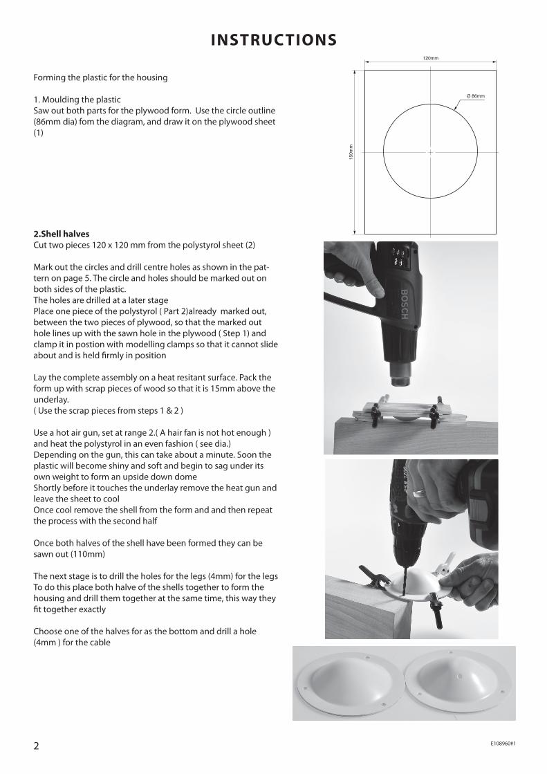
Forming the plastic for the housing 1. Moulding the plastic Saw out both parts for the plywood form. Use the circle outline (86mm dia) fom the diagram, and draw it on the plywood sheet (1)
INSTRUCTIONS
2.Shell halves Cut two pieces 120 x 120 mm from the polystyrol sheet (2) Mark out the circles and drill centre holes as shown in the pat-tern on page 5. The circle and holes should be marked out on both sides of the plastic. The holes are drilled at a later stage Place one piece of the polystyrol ( Part 2)already marked out, between the two pieces of plywood, so that the marked out hole lines up with the sawn hole in the plywood ( Step 1) and clamp it in postion with modelling clamps so that it cannot slide about and is held firmly in position Lay the complete assembly on a heat resitant surface. Pack the form up with scrap pieces of wood so that it is 15mm above the underlay. ( Use the scrap pieces from steps 1 & 2 ) Use a hot air gun, set at range 2.( A hair fan is not hot enough ) and heat the polystyrol in an even fashion ( see dia.) Depending on the gun, this can take about a minute. Soon the plastic will become shiny and soft and begin to sag under its own weight to form an upside down dome Shortly before it touches the underlay remove the heat gun and leave the sheet to cool Once cool remove the shell from the form and and then repeat the process with the second half Once both halves of the shell have been formed they can be sawn out (110mm) The next stage is to drill the holes for the legs (4mm) for the legs To do this place both halve of the shells together to form the housing and drill them together at the same time, this way they fit together exactly Choose one of the halves for as the bottom and drill a hole (4mm ) for the cable
2 E108960#1
150m
m
120mm
Ø 86mm
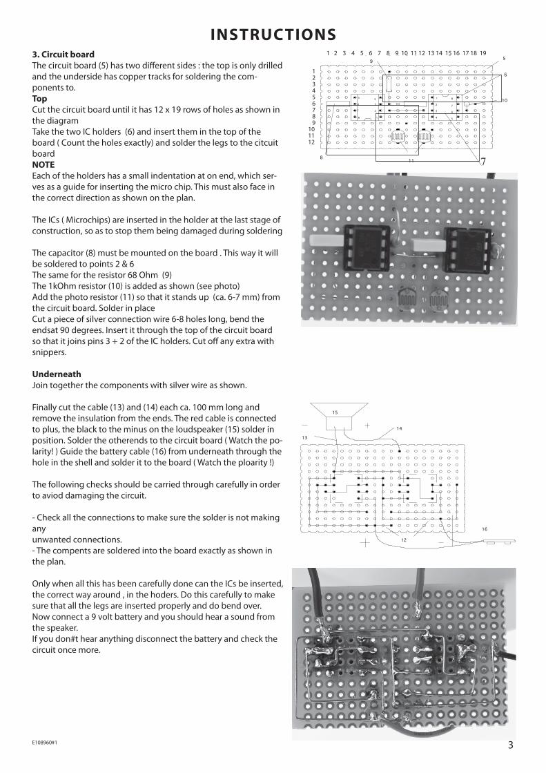
3. Circuit board The circuit board (5) has two different sides : the top is only drilled and the underside has copper tracks for soldering the com-ponents to. Top Cut the circuit board until it has 12 x 19 rows of holes as shown in the diagram Take the two IC holders (6) and insert them in the top of the board ( Count the holes exactly) and solder the legs to the citcuit board NOTE Each of the holders has a small indentation at on end, which ser-ves as a guide for inserting the micro chip. This must also face in the correct direction as shown on the plan. The ICs ( Microchips) are inserted in the holder at the last stage of construction, so as to stop them being damaged during soldering The capacitor (8) must be mounted on the board . This way it will be soldered to points 2 & 6 The same for the resistor 68 Ohm (9) The 1kOhm resistor (10) is added as shown (see photo) Add the photo resistor (11) so that it stands up (ca. 6-7 mm) from the circuit board. Solder in place Cut a piece of silver connection wire 6-8 holes long, bend the endsat 90 degrees. Insert it through the top of the circuit board so that it joins pins 3 + 2 of the IC holders. Cut off any extra with snippers. Underneath Join together the components with silver wire as shown. Finally cut the cable (13) and (14) each ca. 100 mm long and remove the insulation from the ends. The red cable is connected to plus, the black to the minus on the loudspeaker (15) solder in position. Solder the otherends to the circuit board ( Watch the po-larity! ) Guide the battery cable (16) from underneath through the hole in the shell and solder it to the board ( Watch the ploarity !) The following checks should be carried through carefully in order to aviod damaging the circuit. - Check all the connections to make sure the solder is not making any unwanted connections. - The compents are soldered into the board exactly as shown in the plan. Only when all this has been carefully done can the ICs be inserted, the correct way around , in the hoders. Do this carefully to make sure that all the legs are inserted properly and do bend over. Now connect a 9 volt battery and you should hear a sound from the speaker. If you don#t hear anything disconnect the battery and check the circuit once more.
INSTRUCTIONS
7
1 2 3 4 5 6 7 8 9 10 11 12
1 2 3 4 5 6 7 8 9 10 11 12 13 14 15 16 17 18 19
3E108960#1
12
16
15
13
14
8
7
6
811
8
7
6
5
4
3
2
14
3
2
1
10
5
9
Skizze I
6
5
12
16
15
13
14
8
7
6
811
8
7
6
5
4
3
2
14
3
2
1
10
5
9
Skizze I
6
5
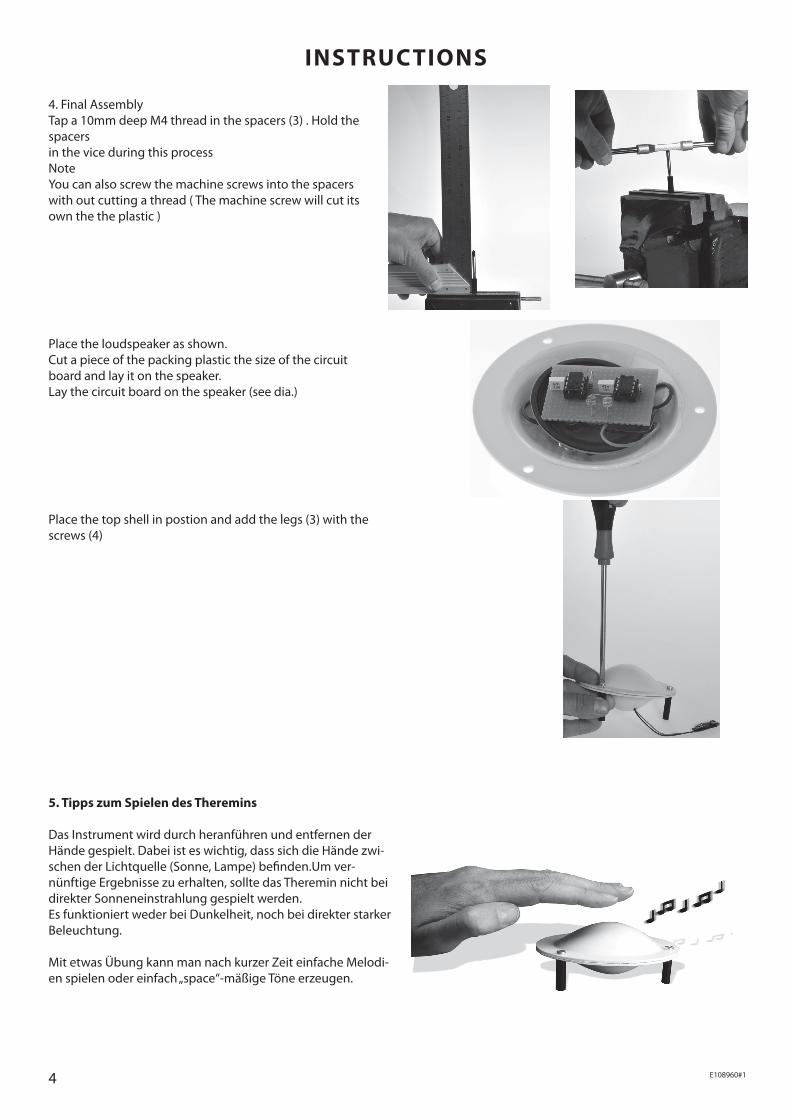
4. Final Assembly Tap a 10mm deep M4 thread in the spacers (3) . Hold the spacers in the vice during this process Note You can also screw the machine screws into the spacers with out cutting a thread ( The machine screw will cut its own the the plastic ) Place the loudspeaker as shown. Cut a piece of the packing plastic the size of the circuit board and lay it on the speaker. Lay the circuit board on the speaker (see dia.) Place the top shell in postion and add the legs (3) with the screws (4)
INSTRUCTIONS
5. Tipps zum Spielen des Theremins Das Instrument wird durch heranführen und entfernen der Hände gespielt. Dabei ist es wichtig, dass sich die Hände zwi-schen der Lichtquelle (Sonne, Lampe) befinden.Um ver- nünftige Ergebnisse zu erhalten, sollte das Theremin nicht bei direkter Sonneneinstrahlung gespielt werden. Es funktioniert weder bei Dunkelheit, noch bei direkter starker Beleuchtung. Mit etwas Übung kann man nach kurzer Zeit einfache Melodi-en spielen oder einfach „space“-mäßige Töne erzeugen.
4 E108960#1
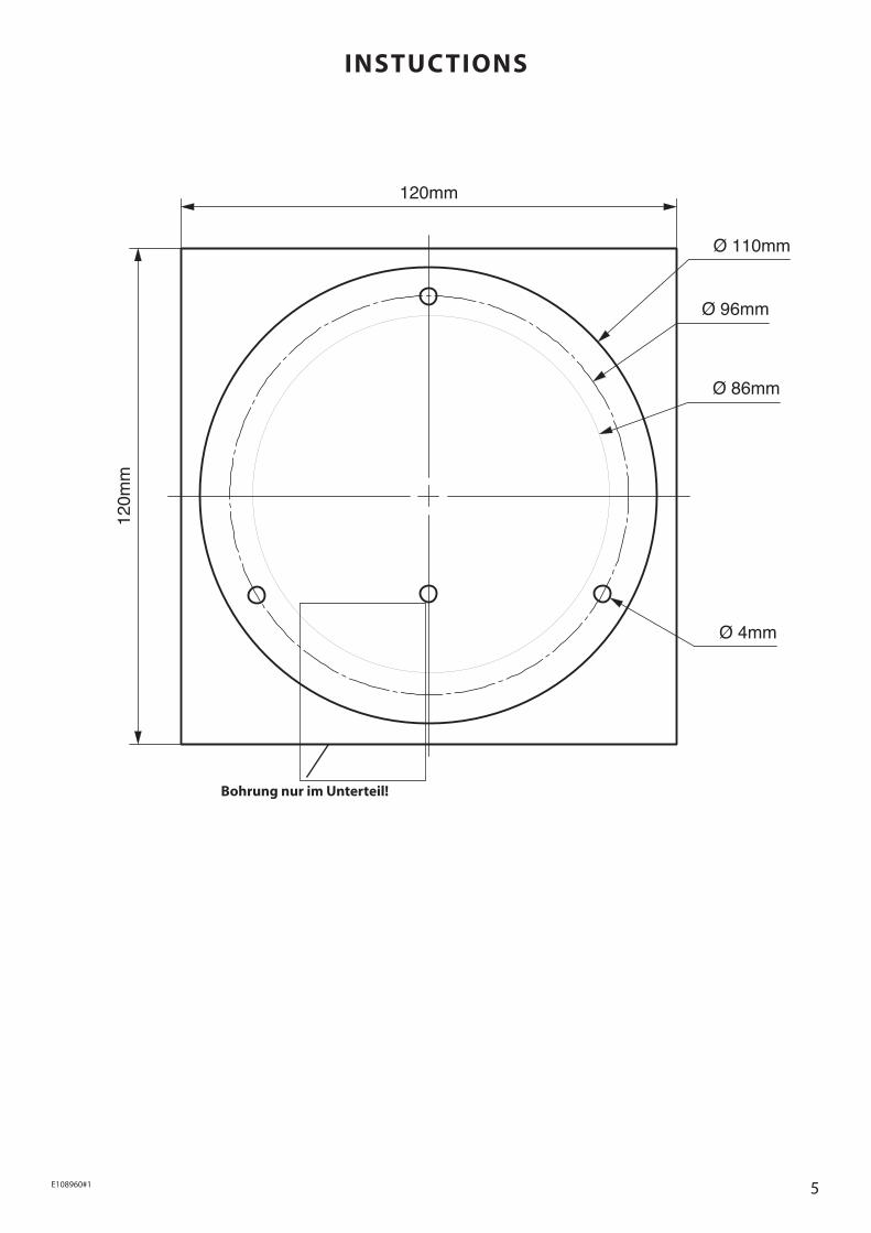
Bohrung nur im Unterteil!
INSTUCTIONS
5E108960#1
Ø 110mm
Ø 96mm
Ø 86mm
Ø 4mm
120mm
120m
m