thermal and mechanical design guide - intel · 2 thermal and mechanical design guide information in...
TRANSCRIPT
Document Number: 320840-003
Intel® X58 Express ChipsetThermal and Mechanical Design Guide
November 2009

2 Thermal and Mechanical Design Guide
INFORMATION IN THIS DOCUMENT IS PROVIDED IN CONNECTION WITH INTEL® PRODUCTS. NO LICENSE, EXPRESS OR IMPLIED, BY ESTOPPEL OR OTHERWISE, TO ANY INTELLECTUAL PROPERTY RIGHTS IS GRANTED BY THIS DOCUMENT. EXCEPT AS PROVIDED IN INTEL'S TERMS AND CONDITIONS OF SALE FOR SUCH PRODUCTS, INTEL ASSUMES NO LIABILITY WHATSOEVER, AND INTEL DISCLAIMS ANY EXPRESS OR IMPLIED WARRANTY, RELATING TO SALE AND/OR USE OF INTEL PRODUCTS INCLUDING LIABILITY OR WARRANTIES RELATING TO FITNESS FOR A PARTICULAR PURPOSE, MERCHANTABILITY, OR INFRINGEMENT OF ANY PATENT, COPYRIGHT OR OTHER INTELLECTUAL PROPERTY RIGHT. Intel products are not intended for use in medical, life saving, or life sustaining applications.
Intel may make changes to specifications and product descriptions at any time, without notice.
Designers must not rely on the absence or characteristics of any features or instructions marked “reserved” or “undefined.” Intel reserves these for future definition and shall have no responsibility whatsoever for conflicts or incompatibilities arising from future changes to them.
The Intel® X58 Express Chipset IOH may contain design defects or errors known as errata which may cause the product to deviate from published specifications. Current characterized errata are available on request.
Contact your local Intel sales office or your distributor to obtain the latest specifications and before placing your product order.
Intel and the Intel logo are trademarks of Intel Corporation in the U.S. and other countries.
* Other brands and names may be claimed as the property of others.
Copyright © 2008-2009, Intel Corporation.
Thermal and Mechanical Design Guide 3
Contents
1 Introduction ..............................................................................................................71.1 Design Flow........................................................................................................71.2 Definition of Terms ..............................................................................................81.3 Reference Documents ..........................................................................................8
2 Packaging Technology ...............................................................................................92.1 Non-Critical to Function Solder Joints ................................................................... 112.2 Package Mechanical Requirements....................................................................... 12
3 Thermal Specifications ............................................................................................ 133.1 Thermal Design Power (TDP) .............................................................................. 133.2 Case Temperature ............................................................................................. 13
4 Thermal Metrology .................................................................................................. 154.1 Die Temperature Measurements .......................................................................... 15
4.1.1 Zero Degree Angle Attach Methodology ..................................................... 154.2 Airflow Characterization ..................................................................................... 17
5 ATX Reference Thermal Solution.............................................................................. 195.1 Operating Environment ...................................................................................... 195.2 Board-Level Components Keepout Dimensions ...................................................... 225.3 Reference Heatsink Thermal Solution Assembly ..................................................... 235.4 Mechanical Design Envelope ............................................................................... 23
5.4.1 Extruded Heatsink Profiles ....................................................................... 235.4.2 Heatsink Orientation ............................................................................... 235.4.3 Thermal Interface Material....................................................................... 235.4.4 Heatsink Clip ......................................................................................... 245.4.5 Anchor.................................................................................................. 24
5.5 Reliability Guidelines.......................................................................................... 255.6 Alternate Heatsink Thermal Solution Assembly ...................................................... 255.7 Alternate Heatsink Mechanical Design Envelope..................................................... 27
5.7.1 Extruded Heatsink Profiles ....................................................................... 275.7.2 Heatsink Clip ......................................................................................... 275.7.3 Anchor.................................................................................................. 285.7.4 Ramp Retainer....................................................................................... 285.7.5 Thermal Interface Material....................................................................... 28
A Thermal Solution Component Suppliers ................................................................... 29
B Mechanical Drawings for Package & Reference Thermal Solution ............................ 31
C Mechanical Drawings for Alternate Thermal Solution............................................... 35
4 Thermal and Mechanical Design Guide
Figures1-1 Thermal Design Process ............................................................................................. 72-1 IOH Package Dimensions (Top View)............................................................................ 92-2 IOH Package Dimensions (Side View) ........................................................................... 92-3 IOH Package Dimensions (Bottom View)......................................................................102-4 Non-Critical to Function Solder Joints ..........................................................................114-1 Thermal Solution Decision Flow Chart..........................................................................164-2 Zero Degree Angle Attach Heatsink Modifications ..........................................................164-3 Zero Degree Angle Attach Methodology (Top View) .......................................................174-4 Airflow and Temperature Measurement Locations..........................................................175-1 ATX Boundary Conditions ..........................................................................................205-2 Side View of ATX Boundary Conditions ........................................................................215-3 Heatsink Board Component Keepout ...........................................................................225-4 Reference Heatsink Assembly.....................................................................................235-5 Alternate Heatsink Assembly......................................................................................255-6 Retention Mechanism Component Keepout Zones for Alternate Heatsink ..........................265-7 Retention Mechanism Component Keepout Zones for Alternate Heatsink ..........................27B-1 IOH Package Drawing...............................................................................................32B-2 Heatsink Extrusion Drawing.......................................................................................33B-3 Z-Clip Wire .............................................................................................................34C-1 Heatsink Extrusion Drawing.......................................................................................36C-2 Heat Sink Extrusion Detail.........................................................................................37C-3 Anchor ...................................................................................................................38C-4 Ramp Retainer - Page 1............................................................................................39C-5 Ramp Retainer - Page 2............................................................................................40C-6 Wire Preload Clip .....................................................................................................41
Tables3-1 Intel® X58 Express Chipset IOH Thermal Design Power .................................................133-2 Intel® X58 Express ChipsetThermal Specification ..........................................................135-1 IOH Thermal Solution Boundary Conditions ..................................................................205-2 Honeywell PCM45 F* TIM Performance as a Function of Attach Pressure...........................245-3 Reliability Guidelines.................................................................................................25A-1 Reference Heatsink Enabled Components.....................................................................29A-2 Alternate Heatsink - Preload Wavesolder Heatsink (PWHS) Components...........................29A-3 Supplier Contact Information .....................................................................................29B-1 Mechanical Drawing List ............................................................................................31C-1 Mechanical Drawing List ............................................................................................35
Thermal and Mechanical Design Guide 5
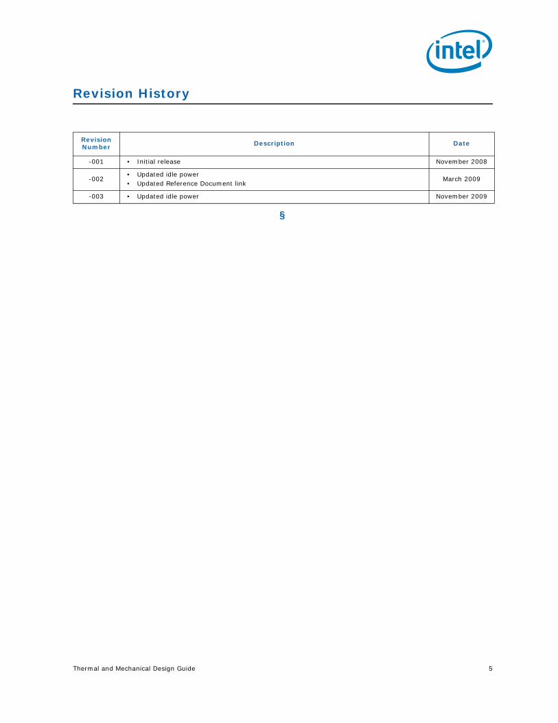
Revision History
§
Revision Number Description Date
-001 • Initial release November 2008
-002• Updated idle power• Updated Reference Document link
March 2009
-003 • Updated idle power November 2009

6 Thermal and Mechanical Design Guide
Thermal and Mechanical Design Guide 7
Introduction
1 Introduction
The goals of this document are to:
• Outline the thermal and mechanical operating limits and specifications for the Intel® X58 Express Chipset IOH.
• Describe reference thermal solutions that meet the specifications of the Intel® X58 Express Chipset IOH.
Properly designed thermal solutions provide adequate cooling to maintain the Intel® X58 Express Chipset IOH case temperatures at or below thermal specifications. This is accomplished by providing a low local-ambient temperature, ensuring adequate local airflow, and minimizing the case to local-ambient thermal resistance. By maintaining the IOH case temperature at or below the specified limits, a system designer can ensure the proper functionality, performance, and reliability of the IOH. Operation outside the functional limits can cause data corruption or permanent damage to the component.
The simplest and most cost-effective method to improve the inherent system cooling characteristics is through careful chassis design and placement of fans, vents, and ducts. When additional cooling is required, component thermal solutions may be implemented in conjunction with system thermal solutions. The size of the fan or heatsink can be varied to balance size and space constraints with acoustic noise.
This document addresses thermal design and specifications for the Intel® X58 Express Chipset IOH component only. For thermal design information on other chipset components, refer to the respective component TMDG. For the ICH10, refer to the Intel® I/O Controller Hub 10 (ICH10) Thermal and Mechanical Design Guidelines.
Note: Unless otherwise specified, the term “IOH” refers to the Intel® X58 Express Chipset IOH.
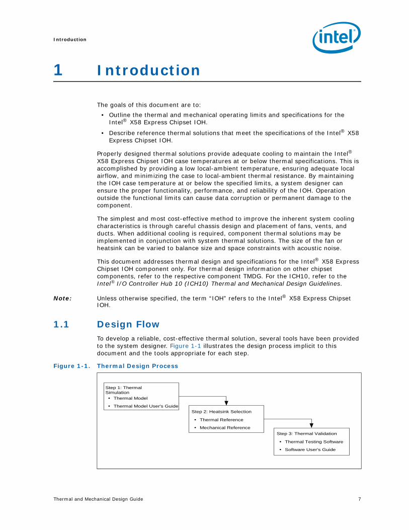
1.1 Design FlowTo develop a reliable, cost-effective thermal solution, several tools have been provided to the system designer. Figure 1-1 illustrates the design process implicit to this document and the tools appropriate for each step.
Figure 1-1. Thermal Design Process
Thermal Model
Thermal Model User's Guide
Step 1: ThermalSimulation
Thermal Reference
Mechanical Reference
Step 2: Heatsink Selection
Thermal Testing Software
Software User's Guide
Step 3: Thermal Validation
Introduction
8 Thermal and Mechanical Design Guide
1.2 Definition of Terms
1.3 Reference DocumentsThe reader of this specification should also be familiar with material and concepts presented in the following documents.
§
Term Description
FC-BGA
Flip Chip Ball Grid Array. A package type defined by a plastic substrate where a die is mounted using an underfill C4 (Controlled Collapse Chip Connection) attach style. The primary electrical interface is an array of solder balls attached to the substrate opposite the die. Note that the device arrives at the customer with solder balls attached.
BLT Bond Line Thickness. Final settled thickness of the thermal interface material after installation of heatsink.
Intel® QuickPath
Interconnect
The Physical layer of Intel® QuickPath interconnect is a link based interconnect specification for Intel processors, chipset and I/O bridge components.
IOHInput Output Hub. The IO Controller Hub component that contains the Intel® QuickPath Interface to the processor, and PCI Express* interface. It communicates with the ICH10 over a proprietary interconnect called the Direct Media Interface (DMI).
Intel ICH10 I/O Controller Hub 10.
Tcase_maxDie temperature allowed. This temperature is measured at the geometric center of the top of the die.
TDP Thermal design power. Thermal solutions should be designed to dissipate this target power level. TDP is not the maximum power that the IOH can dissipate.
Title Location
Intel® X58 Express Chipset Datasheet http://www.intel.com/Assets/PDF/datasheet/320839.pdf
Intel® I/O Controller Hub ICH10 Thermal Mechanical Design Guidelines http://www.intel.com/design/chipsets/
designex/319975.pdf
Thermal and Mechanical Design Guide 9
Packaging Technology
2 Packaging Technology
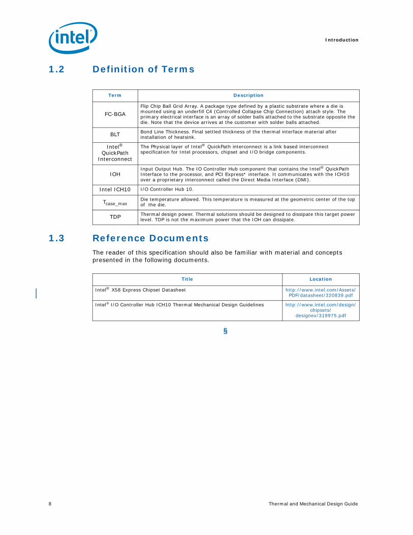
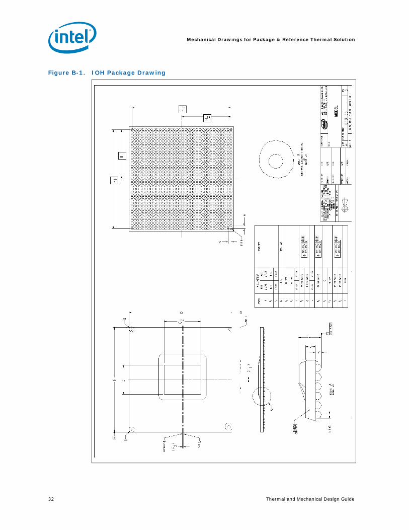
The IOH uses a 37.5 mm, 8-layer flip chip ball grid array (FC-BGA) package (see Figure 2-1, Figure 2-2, and Figure 2-3). The complete package drawing can be found at Figure B-1. For information on the ICH10 package, refer to the Intel® I/O Controller Hub 10 (ICH10) Family Thermal and Mechanical Design Guidelines.
Figure 2-1. IOH Package Dimensions (Top View)
Figure 2-2. IOH Package Dimensions (Side View)
Die
37.5 mm.
37.5 mm.13.8 mm.
10.6 mm
HandlingExclusion
Area
- C -
See Note 3
Seating Plane
See note 1
See note 4
Die
NOTES:
1. Primary datum-C and seating plan are defined by the spherical crowns of the solder balls (shown before motherboard attach)
2. All dimensions and tolerances conform to ANSI Y14.5M-1994
3. BGA has a pre-SMT height of 0.5±0.10 mm. Top of die above the motherboard after reflow is 2.36 ± 0.24 mm.
4. Shown before motherboard attach; FCBGA has a convex (dome shape) orientation before reflow and is expected to have a slightly concave (bowl shaped) orientation after reflow
0.20
0.20
0.5 ± 0.1 mm
2.48 ± 0.24 mm
1.98 ± 0.14 mm
Substrate
0.82 ± 0.05 mm

Packaging Technology
10 Thermal and Mechanical Design Guide
Notes:1. All dimensions are in millimeters.2. All dimensions and tolerances conform to ANSI Y14.5M-1994.
Figure 2-3. IOH Package Dimensions (Bottom View)
37.5 + 0.05
2822 26242018161412108642 36343230
A
AJ
AE
AC
AA
U
R
N
L
J
G
E
C
W
AG
AL
AN
AR
AH
AF
AD
AB
Y
V
T
P
M
K
H
F
D
AK
AM
AP
AT
B
A
B37.5 + 0.05
C A0.2
35x 1.016
35.56
35.56
35X 1.016
11 2523211917151397531 27 29 33 3531
C0.2
Thermal and Mechanical Design Guide 11
Packaging Technology
2.1 Non-Critical to Function Solder Joints
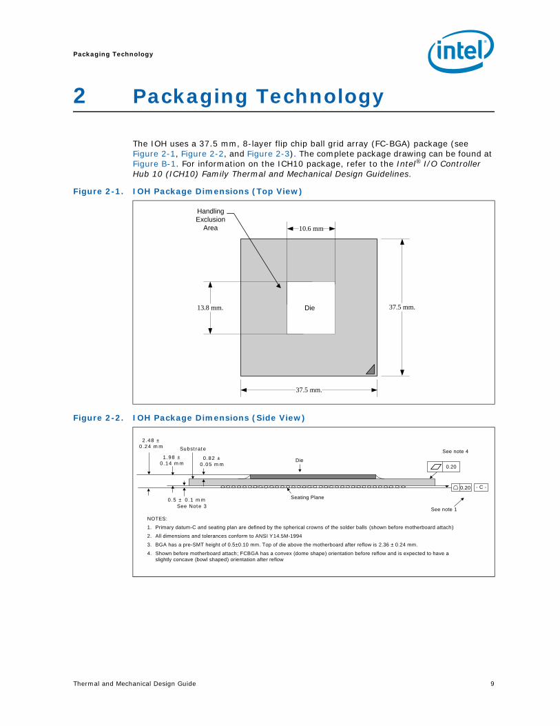
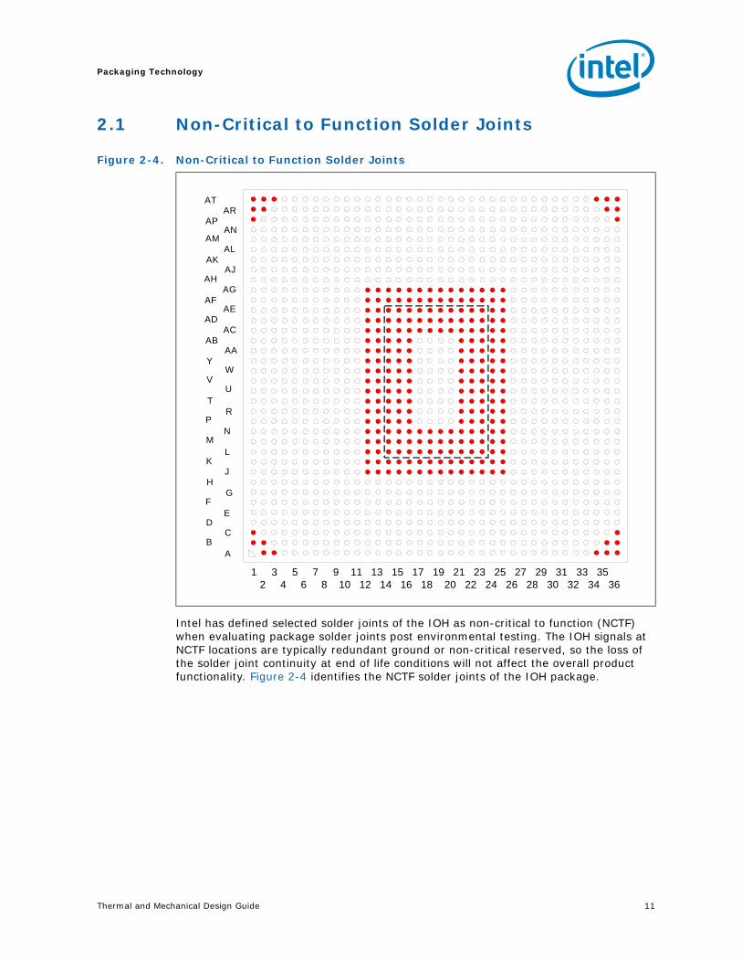
Intel has defined selected solder joints of the IOH as non-critical to function (NCTF) when evaluating package solder joints post environmental testing. The IOH signals at NCTF locations are typically redundant ground or non-critical reserved, so the loss of the solder joint continuity at end of life conditions will not affect the overall product functionality. Figure 2-4 identifies the NCTF solder joints of the IOH package.
Figure 2-4. Non-Critical to Function Solder Joints
1 3 5 7 9 11 13 15 17 19 21 23 25 27 29 31 33 35 2 4 6 8 10 12 14 16 18 20 22 24 26 28 30 32 34 36
ATAR
APAN
AMAL
AKAJ
AHAG
AFAE
ADAC
ABAA
YW
VU
TR
PN
ML
KJ
HG
FE
DC
BA
Packaging Technology
12 Thermal and Mechanical Design Guide
2.2 Package Mechanical RequirementsThe IOH package has a bare die that is capable of sustaining a maximum static normal load of 15 lbf (67N). These mechanical load limits must not be exceeded during heatsink installation, mechanical stress testing, standard shipping conditions, and/or any other use condition.
Note: The heatsink attach solutions must not induce continuous stress to the IOH package with the exception of a uniform load to maintain the heatsink-to-package thermal interface.
Note: These specifications apply to uniform compressive loading in a direction perpendicular to the die top surface.
Note: These specifications are based on limited testing for design characterization. Loading limits are for the package only.
§
Thermal and Mechanical Design Guide 13
Thermal Specifications
3 Thermal Specifications
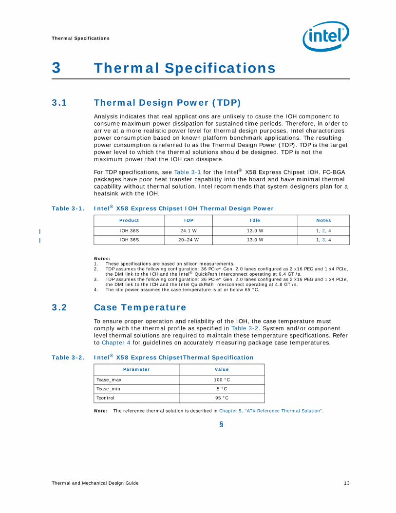
3.1 Thermal Design Power (TDP)Analysis indicates that real applications are unlikely to cause the IOH component to consume maximum power dissipation for sustained time periods. Therefore, in order to arrive at a more realistic power level for thermal design purposes, Intel characterizes power consumption based on known platform benchmark applications. The resulting power consumption is referred to as the Thermal Design Power (TDP). TDP is the target power level to which the thermal solutions should be designed. TDP is not the maximum power that the IOH can dissipate.
For TDP specifications, see Table 3-1 for the Intel® X58 Express Chipset IOH. FC-BGA packages have poor heat transfer capability into the board and have minimal thermal capability without thermal solution. Intel recommends that system designers plan for a heatsink with the IOH.
Notes:1. These specifications are based on silicon measurements.2. TDP assumes the following configuration: 36 PCIe* Gen. 2.0 lanes configured as 2 x16 PEG and 1 x4 PCIe,
the DMI link to the ICH and the Intel® QuickPath Interconnect operating at 6.4 GT /s. 3. TDP assumes the following configuration: 36 PCIe* Gen. 2.0 lanes configured as 2 x16 PEG and 1 x4 PCIe,
the DMI link to the ICH and the Intel QuickPath Interconnect operating at 4.8 GT /s. 4. The idle power assumes the case temperature is at or below 65 °C.
3.2 Case TemperatureTo ensure proper operation and reliability of the IOH, the case temperature must comply with the thermal profile as specified in Table 3-2. System and/or component level thermal solutions are required to maintain these temperature specifications. Refer to Chapter 4 for guidelines on accurately measuring package case temperatures.
Note: The reference thermal solution is described in Chapter 5, “ATX Reference Thermal Solution”.
§
Table 3-1. Intel® X58 Express Chipset IOH Thermal Design Power
Product TDP Idle Notes
IOH 36S 24.1 W 13.0 W 1, 2, 4
IOH 36S 20–24 W 13.0 W 1, 3, 4
Table 3-2. Intel® X58 Express ChipsetThermal Specification
Parameter Value
Tcase_max 100 °C
Tcase_min 5 °C
Tcontrol 95 °C

Thermal Specifications
14 Thermal and Mechanical Design Guide
Thermal and Mechanical Design Guide 15
Thermal Metrology
4 Thermal Metrology
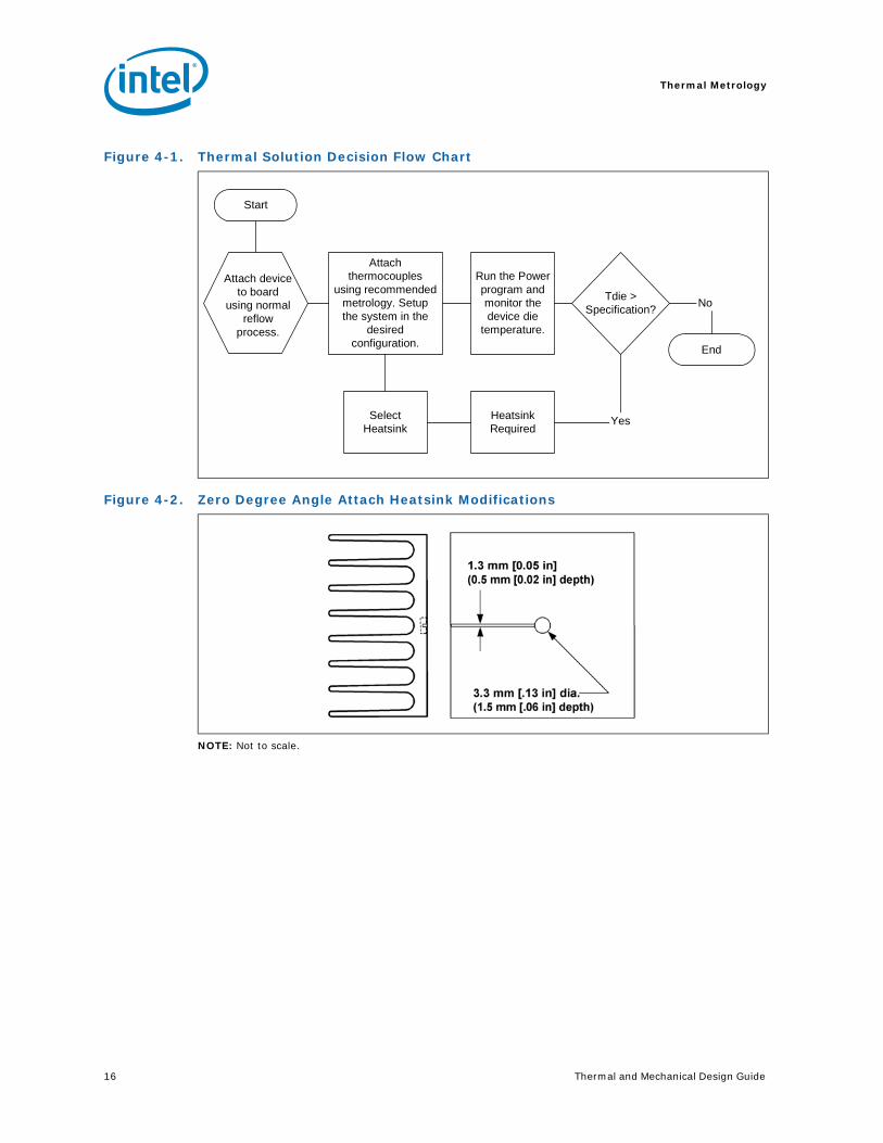
The system designer must make temperature measurements to accurately determine the thermal performance of the system. Intel has established guidelines for proper techniques to measure the IOH die temperatures. Section 4.1 provides guidelines on how to accurately measure the IOH die temperatures. The flowchart in Figure 4-1 offers useful guidelines for thermal performance and evaluation.
4.1 Die Temperature MeasurementsTo ensure functionality and reliability, the Tcase of the IOH must be maintained at or between the maximum/minimum operating range of the temperature specification as noted in Table 3-2. The surface temperature at the geometric center of the die corresponds to Tcase. Measuring Tcase requires special care to ensure an accurate temperature measurement.
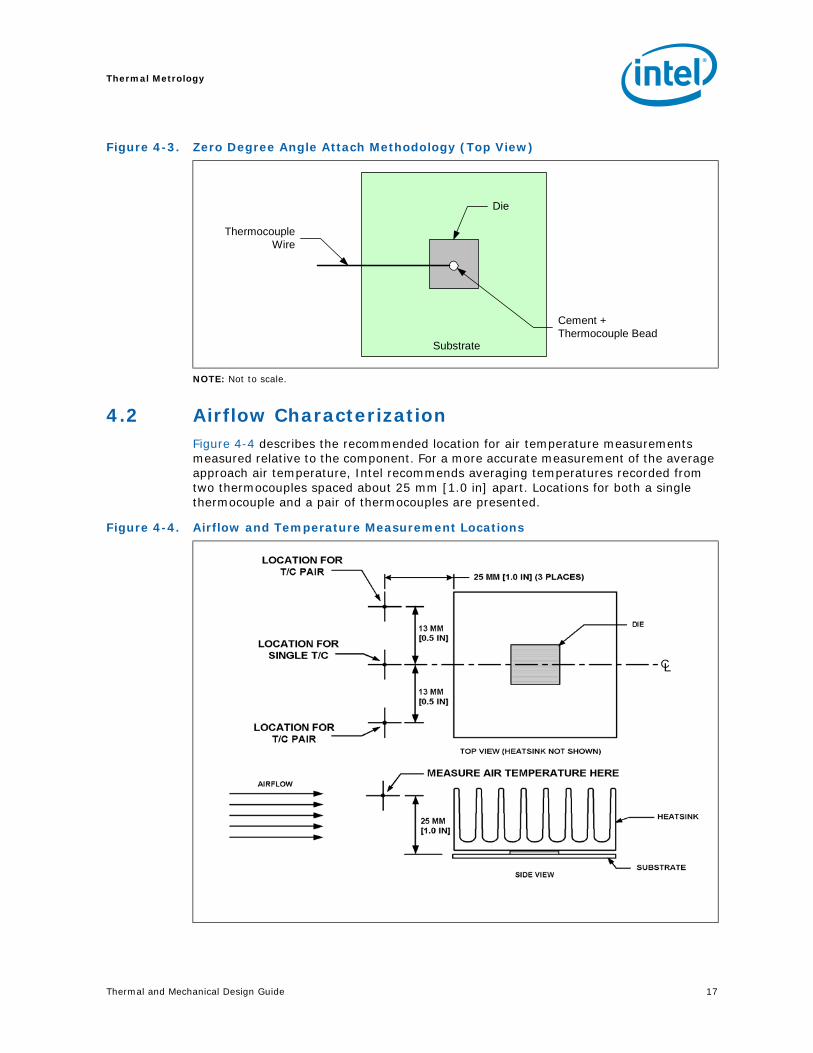
Temperature differences between the temperature of a surface and the surrounding local ambient air can introduce errors in the measurements. The measurement errors could be due to a poor thermal contact between the thermocouple junction and the surface of the package, heat loss by radiation and/or convection, conduction through thermocouple leads, and/or contact between the thermocouple cement and the heatsink base (if a heatsink is used). For maximum measurement accuracy, only the 0° thermocouple attach approach is recommended.
4.1.1 Zero Degree Angle Attach Methodology
1. Mill a 3.3 mm (0.13 in.) diameter and 1.5 mm (0.06 in.) deep hole centered on the bottom of the heatsink base.
2. Mill a 1.3 mm (0.05 in.) wide and 0.5 mm (0.02 in.) deep slot from the centered hole to one edge of the heatsink. The slot should be parallel to the heatsink fins (see Figure 4-2).
3. Attach thermal interface material (TIM) to the bottom of the heatsink base.
4. Cut out portions of the TIM to make room for the thermocouple wire and bead. The cutouts should match the slot and hole milled into the heatsink base.
5. Attach a 36 gauge or smaller calibrated K-type thermocouple bead or junction to the center of the top surface of the die using a high thermal conductivity cement. During this step, ensure no contact is present between the thermocouple cement and the heatsink base because any contact will affect the thermocouple reading. It is critical that the thermocouple bead makes contact with the die (see Figure 4-3).
6. Attach heatsink assembly to the IOH and route thermocouple wires out through the milled slot.
Thermal Metrology
16 Thermal and Mechanical Design Guide
NOTE: Not to scale.
Figure 4-1. Thermal Solution Decision Flow Chart
Figure 4-2. Zero Degree Angle Attach Heatsink Modifications
Attachthermocouples
using recommendedmetrology. Setupthe system in the
desiredconfiguration.
Tdie >Specification?
No
YesHeatsinkRequired
SelectHeatsink
End
Start
Run the Powerprogram andmonitor thedevice die
temperature.
Attach deviceto board
using normalreflow
process.
Thermal and Mechanical Design Guide 17
Thermal Metrology
NOTE: Not to scale.
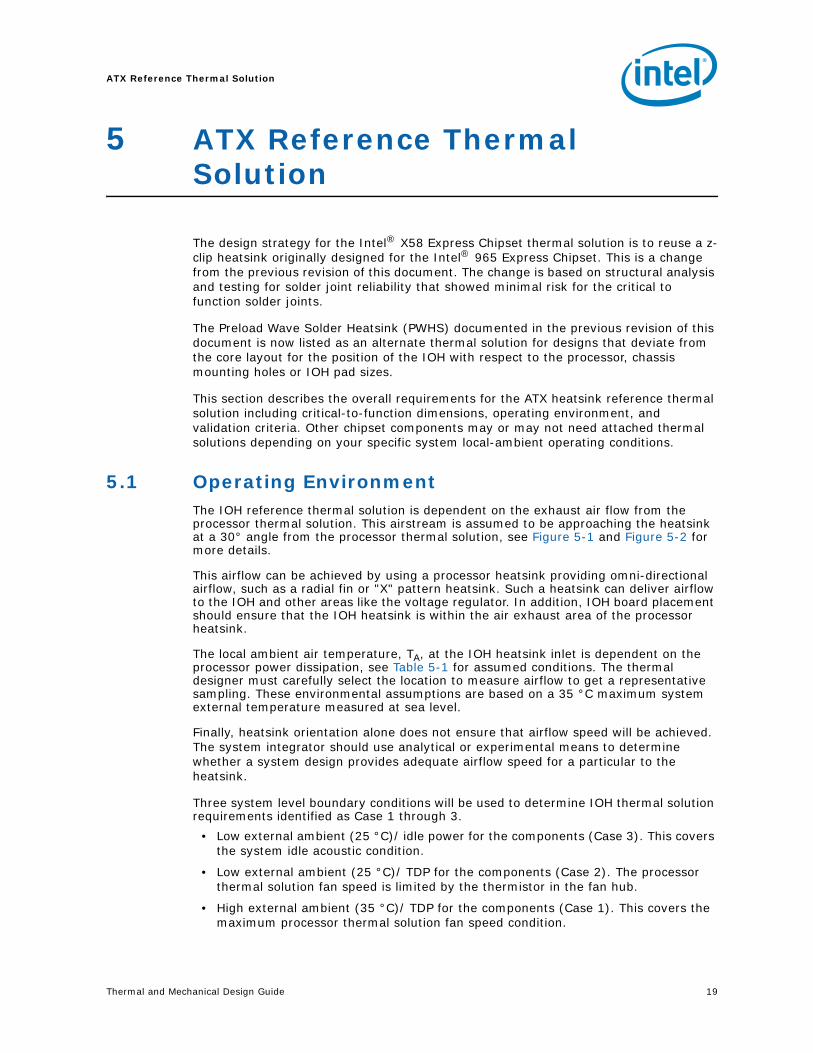
4.2 Airflow CharacterizationFigure 4-4 describes the recommended location for air temperature measurements measured relative to the component. For a more accurate measurement of the average approach air temperature, Intel recommends averaging temperatures recorded from two thermocouples spaced about 25 mm [1.0 in] apart. Locations for both a single thermocouple and a pair of thermocouples are presented.
Figure 4-3. Zero Degree Angle Attach Methodology (Top View)
Cement +Thermocouple Bead
Die
ThermocoupleWire
Substrate
Figure 4-4. Airflow and Temperature Measurement Locations

Thermal Metrology
18 Thermal and Mechanical Design Guide
Airflow velocity can be measured using sensors that combine air velocity and temperature measurements. Typical airflow sensor technology may include hot wire anemometers. Figure 4-4 provides guidance for airflow velocity measurement locations which should be the same as used for temperature measurement. These locations are for a typical JEDEC test setup and may not be compatible with chassis layouts due to the proximity of the processor to the IOH. The user may have to adjust the locations for a specific chassis. Be aware that sensors may need to be aligned perpendicular to the airflow velocity vector or an inaccurate measurement may result. Measurements should be taken with the chassis fully sealed in its operational configuration to achieve a representative airflow profile within the chassis.
§
Thermal and Mechanical Design Guide 19
ATX Reference Thermal Solution
5 ATX Reference Thermal Solution
The design strategy for the Intel® X58 Express Chipset thermal solution is to reuse a z-clip heatsink originally designed for the Intel® 965 Express Chipset. This is a change from the previous revision of this document. The change is based on structural analysis and testing for solder joint reliability that showed minimal risk for the critical to function solder joints.
The Preload Wave Solder Heatsink (PWHS) documented in the previous revision of this document is now listed as an alternate thermal solution for designs that deviate from the core layout for the position of the IOH with respect to the processor, chassis mounting holes or IOH pad sizes.
This section describes the overall requirements for the ATX heatsink reference thermal solution including critical-to-function dimensions, operating environment, and validation criteria. Other chipset components may or may not need attached thermal solutions depending on your specific system local-ambient operating conditions.
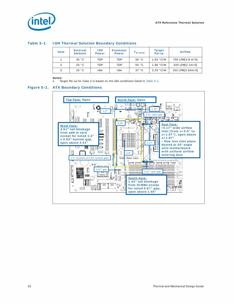
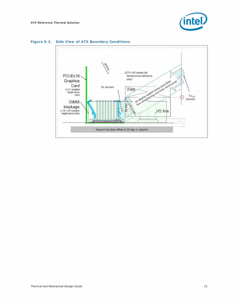
5.1 Operating EnvironmentThe IOH reference thermal solution is dependent on the exhaust air flow from the processor thermal solution. This airstream is assumed to be approaching the heatsink at a 30° angle from the processor thermal solution, see Figure 5-1 and Figure 5-2 for more details.
This airflow can be achieved by using a processor heatsink providing omni-directional airflow, such as a radial fin or "X" pattern heatsink. Such a heatsink can deliver airflow to the IOH and other areas like the voltage regulator. In addition, IOH board placement should ensure that the IOH heatsink is within the air exhaust area of the processor heatsink.
The local ambient air temperature, TA, at the IOH heatsink inlet is dependent on the processor power dissipation, see Table 5-1 for assumed conditions. The thermal designer must carefully select the location to measure airflow to get a representative sampling. These environmental assumptions are based on a 35 °C maximum system external temperature measured at sea level.
Finally, heatsink orientation alone does not ensure that airflow speed will be achieved. The system integrator should use analytical or experimental means to determine whether a system design provides adequate airflow speed for a particular to the heatsink.
Three system level boundary conditions will be used to determine IOH thermal solution requirements identified as Case 1 through 3.
• Low external ambient (25 °C)/ idle power for the components (Case 3). This covers the system idle acoustic condition.
• Low external ambient (25 °C)/ TDP for the components (Case 2). The processor thermal solution fan speed is limited by the thermistor in the fan hub.
• High external ambient (35 °C)/ TDP for the components (Case 1). This covers the maximum processor thermal solution fan speed condition.
ATX Reference Thermal Solution
20 Thermal and Mechanical Design Guide
Notes:1. Target Psi-ca for Case 3 is based on the idle conditions listed in Table 3-1.
Table 5-1. IOH Thermal Solution Boundary Conditions
Case External Ambient
IOH Power
Processor Power TA-Local
Target Psi-ca Airflow
1 35 °C TDP TDP 56 °C 1.83 °C/W 756 LFM[3.8 m/S]
2 25 °C TDP TDP 55 °C 1.86 °C/W 420 LFM[2.1m/S]
3 25 °C Idle Idle 37 °C 3.29 °C/W 163 LFM[0.83m/S]
Figure 5-1. ATX Boundary Conditions
East Face:•4.17” wide airflow inlet (from z=0.0” to z=1.97”), open above z=1.97”• flow into inlet plane ducted at 30° angle onto motherboard with uniform airflow entering duct
North Face: OpenTop Face: Open
West Face:4.51” tall blockage from add-in card except for noted 1.5”x 0.63” bottom gap, open above 4.51”
South Face:1.40” tall blockage from DIMMs except for noted 0.67” gap, open above 1.40”
1.25”1.5”
2.8”
4.17”
1.5” (location of 0.63” bottom gap)
0.67” gap
5.00”
0.52” open gap
0.31” open gap
Thermal and Mechanical Design Guide 21
ATX Reference Thermal Solution
Figure 5-2. Side View of ATX Boundary Conditions
ATX Reference Thermal Solution
22 Thermal and Mechanical Design Guide
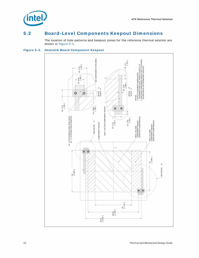
5.2 Board-Level Components Keepout DimensionsThe location of hole patterns and keepout zones for the reference thermal solution are shown in Figure 5-3.
Figure 5-3. Heatsink Board Component Keepout
50 1
.969
[]
67.0
22.6
39
[] 6
0.9
22.3
98
[]
47 1
.850
[]
4X
8.7
6.3
45
[]
4X
5.0
8.2
00
[]
4X
4.1
9.1
65
[]
4X
2.0
95
.082
[]
2X
3.3 .1
30
[]
2X
2.2
9.0
90
[]
2X
5.7
2.2
25
[]
2X
2.5
4.1
00
[]
44 1
.732
[]
CO
MP
ON
EN
T C
EN
TE
R
MA
X 1
.27 [.0
50]
CO
MP
ON
EN
T H
EIG
HT
(NO
N-M
CH
CO
MP
ON
EN
TS
)
NO
CO
MP
ON
EN
TS
TH
IS A
RE
A
NO
TE
S:
1. H
OLE
PLA
CE
ME
NT
FA
BR
ICA
TIO
N
T
OLE
RA
NC
E P
ER
IN
TE
L 4
54979, C
LA
SS
1,2
,32. H
EA
TS
INK
CO
MP
ON
EN
T H
EIG
HT
NO
T T
O E
XC
EE
D
3
8.1
MM
AB
OV
E M
OT
HE
RB
OA
RD
SU
RF
AC
E.
MA
X 1
.78 [.0
70] C
OM
PO
NE
NT
HE
IGH
T
MA
X 1
.55 [.0
60]
CO
MP
ON
EN
T H
EIG
HT
(NO
N-M
CH
CO
MP
ON
EN
TS
)
SE
E D
ET
AIL
A
SE
E D
ET
AIL
B
DE
TA
ILA
SC
ALE
8
4X
0.9
7 [0.0
38] P
LA
TE
D T
HR
U H
OLE
4X
1.4
2 [0.0
56] T
RA
CE
KE
EP
OU
T
DE
TA
ILB
SC
ALE
6
Thermal and Mechanical Design Guide 23
ATX Reference Thermal Solution
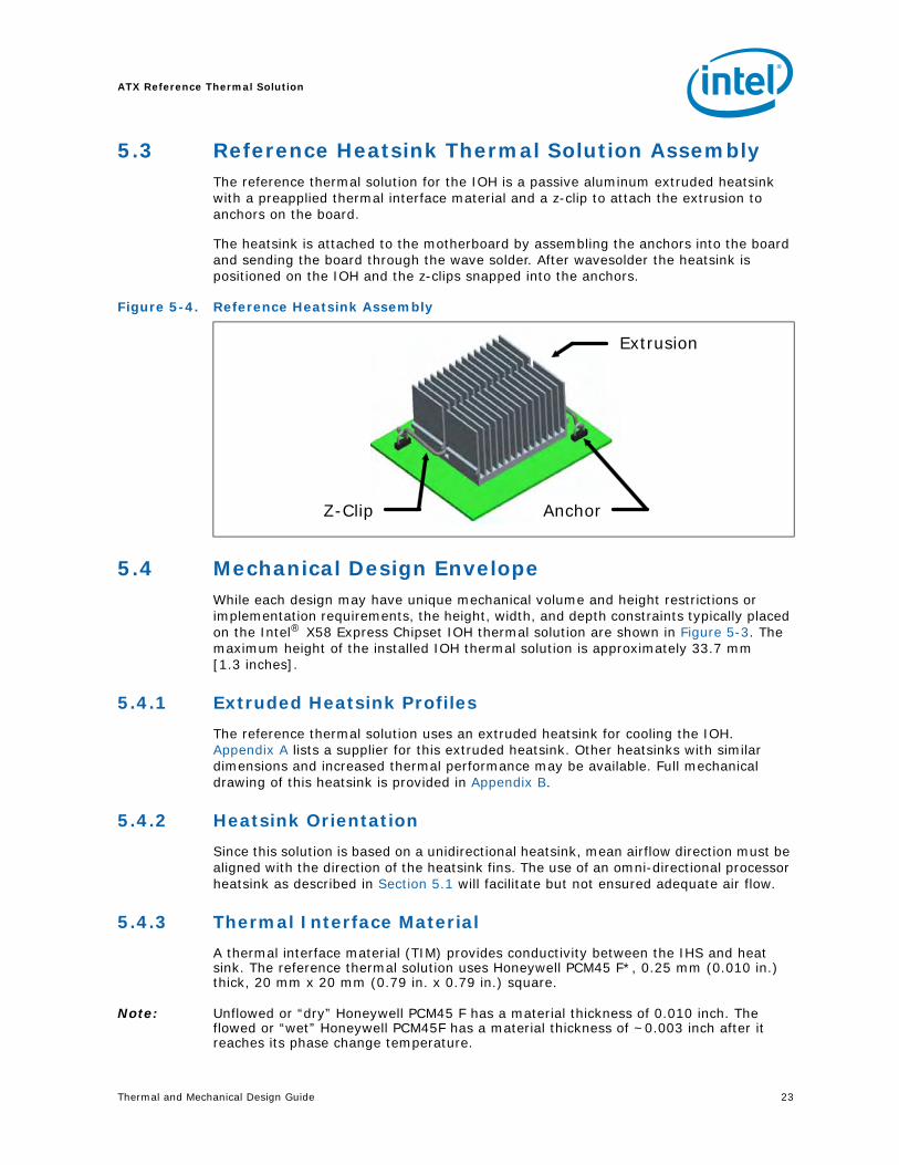
5.3 Reference Heatsink Thermal Solution AssemblyThe reference thermal solution for the IOH is a passive aluminum extruded heatsink with a preapplied thermal interface material and a z-clip to attach the extrusion to anchors on the board.
The heatsink is attached to the motherboard by assembling the anchors into the board and sending the board through the wave solder. After wavesolder the heatsink is positioned on the IOH and the z-clips snapped into the anchors.
5.4 Mechanical Design EnvelopeWhile each design may have unique mechanical volume and height restrictions or implementation requirements, the height, width, and depth constraints typically placed on the Intel® X58 Express Chipset IOH thermal solution are shown in Figure 5-3. The maximum height of the installed IOH thermal solution is approximately 33.7 mm [1.3 inches].
5.4.1 Extruded Heatsink Profiles
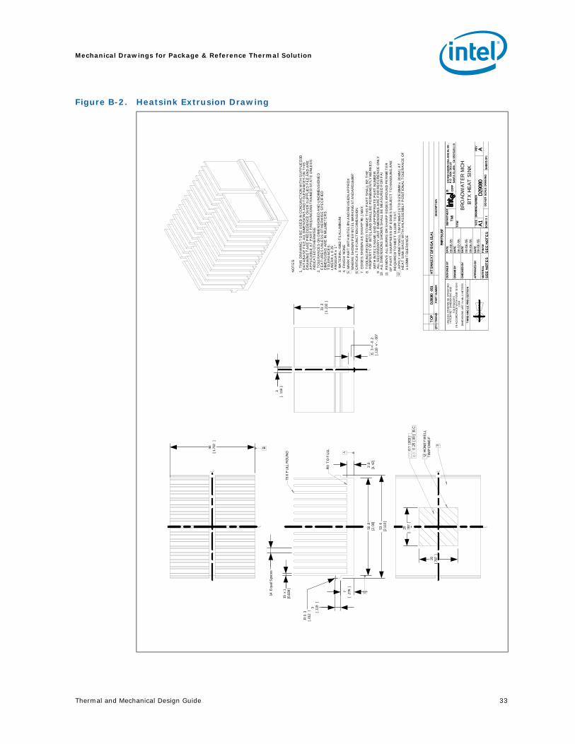
The reference thermal solution uses an extruded heatsink for cooling the IOH. Appendix A lists a supplier for this extruded heatsink. Other heatsinks with similar dimensions and increased thermal performance may be available. Full mechanical drawing of this heatsink is provided in Appendix B.
5.4.2 Heatsink Orientation
Since this solution is based on a unidirectional heatsink, mean airflow direction must be aligned with the direction of the heatsink fins. The use of an omni-directional processor heatsink as described in Section 5.1 will facilitate but not ensured adequate air flow.
5.4.3 Thermal Interface Material
A thermal interface material (TIM) provides conductivity between the IHS and heat sink. The reference thermal solution uses Honeywell PCM45 F*, 0.25 mm (0.010 in.) thick, 20 mm x 20 mm (0.79 in. x 0.79 in.) square.
Note: Unflowed or “dry” Honeywell PCM45 F has a material thickness of 0.010 inch. The flowed or “wet” Honeywell PCM45F has a material thickness of ~0.003 inch after it reaches its phase change temperature.
Figure 5-4. Reference Heatsink Assembly
Z-Clip Anchor
Extrusion
Z-Clip Anchor
Extrusion
ATX Reference Thermal Solution
24 Thermal and Mechanical Design Guide
5.4.3.1 Effect of Pressure on TIM Performance
As mechanical pressure increases on the TIM, the thermal resistance of the TIM decreases. This phenomenon is due to the decrease of the bond line thickness (BLT). BLT is the final settled thickness of the thermal interface material after installation of heatsink. The effect of pressure on the thermal resistance of the Honeywell PCM45 F TIM is shown in Table 5-2.
Intel provides both End of Line and End of Life TIM thermal resistance values of Honeywell PCM45F. End of Line and End of Life TIM thermal resistance values are obtained through measurement on a Test Vehicle similar to Intel® X58 Express Chipset’s physical attributes using an extruded aluminum heatsink. The End of Line value represents the TIM performance post heatsink assembly while the End of Life value is the predicted TIM performance when the product and TIM reaches the end of its life. The heatsink clip provides enough pressure for the TIM to achieve End of Line and End of Life thermal resistances shown in Figure 5-2.
5.4.4 Heatsink Clip
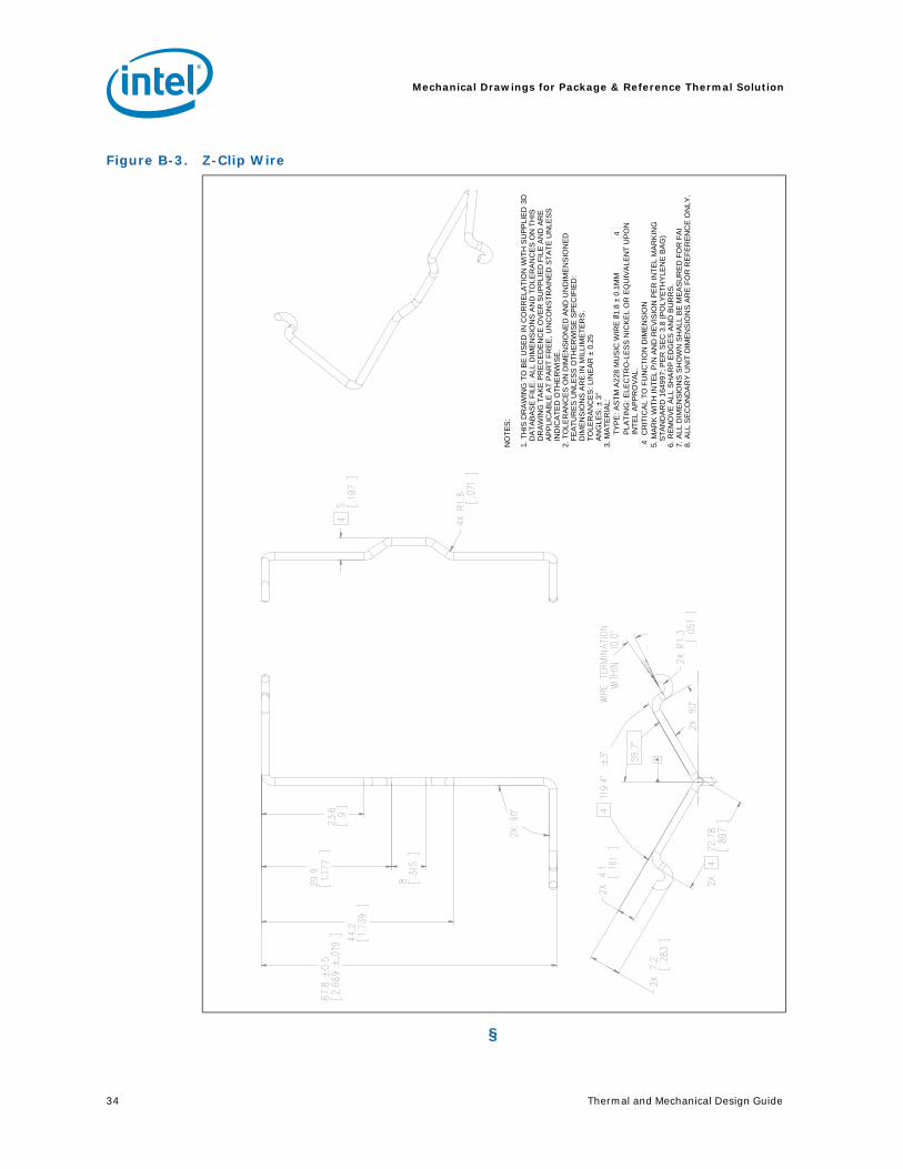
The reference solution Z-clip is a new design to span the previously defined anchor locations. It provide a constant preload on the extrusion for the TIM. See Appendix A for the part number and supplier information. See Appendix B for a mechanical drawings.
5.4.5 Anchor
The anchor from previous z-clip solutions will be reused. By using anchors that are separate from the extrusion the solderability of the anchors is improved. The elimination of the conduction path from pins in the extrusion reduces the chance for cold solder joints. This design incorporates a 45° bent leads to increase the anchor attach reliability over time. See Appendix A for the part number and supplier information. See Appendix B for a mechanical drawings.
Table 5-2. Honeywell PCM45 F* TIM Performance as a Function of Attach Pressure
Pressure on Thermal Solution and Package Interface (PSI)
Thermal Resistance (°C × in2)/W
End of Line End of Life
50 0.533 0.646
Thermal and Mechanical Design Guide 25
ATX Reference Thermal Solution
5.5 Reliability GuidelinesEach motherboard, heatsink and attach combination may vary the mechanical loading of the component. Based on the end user environment, the user should define the appropriate reliability test criteria and carefully evaluate the completed assembly prior to use in high volume. Some general recommendations are shown in Table 5-3.
Notes:1. It is recommended that the above tests be performed on a sample size of at least twelve assemblies from
three lots of material.2. Additional pass/fail criteria may be added at the discretion of the user.
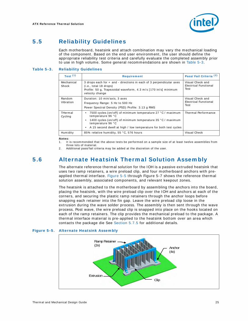
5.6 Alternate Heatsink Thermal Solution AssemblyThe alternate reference thermal solution for the IOH is a passive extruded heatsink that uses two ramp retainers, a wire preload clip, and four motherboard anchors with pre-applied thermal interface. Figure 5-5 through Figure 5-7 shows the reference thermal solution assembly, associated components, and relevant keepout zones.
The heatsink is attached to the motherboard by assembling the anchors into the board, placing the heatsink, with the wire preload clip over the IOH and anchors at each of the corners, and securing the plastic ramp retainers through the anchor loops before snapping each retainer into the fin gap. Leave the wire preload clip loose in the extrusion during the wave solder process. The assembly is then sent through the wave process. Post wave, the wire preload clip is snapped into place on the hooks located on each of the ramp retainers. The clip provides the mechanical preload to the package. A thermal interface material is pre-applied to the heatsink bottom over an area which contacts the package die See Section 5.7.5 for additional details.
Table 5-3. Reliability Guidelines
Test (1) Requirement Pass/Fail Criteria (2)
Mechanical Shock
3 drops each for + and - directions in each of 3 perpendicular axes (i.e., total 18 drops)Profile: 50 g, Trapezoidal waveform, 4.3 m/s [170 in/s] minimum velocity change
Visual Check and Electrical Functional Test
Random Vibration
Duration: 10 min/axis, 3 axes
Frequency Range: 5 Hz to 500 Hz
Power Spectral Density (PSD) Profile: 3.13 g RMS
Visual Check and Electrical Functional Test
THermal Cycling
• 7500 cycles (on/off) of minimum temperature 27 °C / maximum temperature 96 °C
• 1400 cycles (on/off) of minimum temperature 35 °C / maximum temperature 96 °C
• A 15 second dwell at high / low temperature for both test cycles
Thermal Performance
Humidity 85% relative humidity, 55 °C, 576 hours Visual Check
Figure 5-5. Alternate Heatsink Assembly
Anchor(4x)
Extrusion
Ramp Retainer(2x)
Clip
Anchor(4x)
Extrusion
Ramp Retainer(2x)
Clip
ATX Reference Thermal Solution
26 Thermal and Mechanical Design Guide
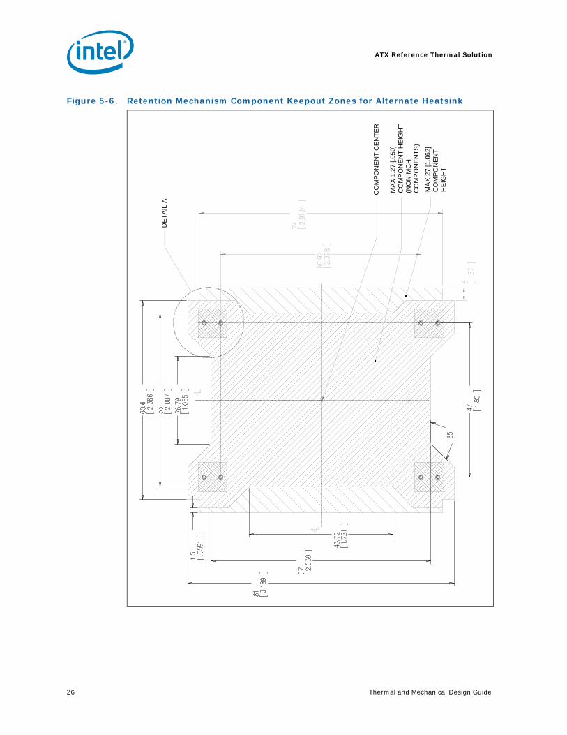
Figure 5-6. Retention Mechanism Component Keepout Zones for Alternate Heatsink
DE
TA
IL A
MA
X 1
.27
[.0
50]
C
OM
PO
NE
NT
HE
IGH
T(N
ON
-MC
H
CO
MP
ON
EN
TS
)
CO
MP
ON
EN
T C
EN
TE
R
MA
X 2
7 [1
.06
2]C
OM
PO
NE
NT
H
EIG
HT
Thermal and Mechanical Design Guide 27
ATX Reference Thermal Solution
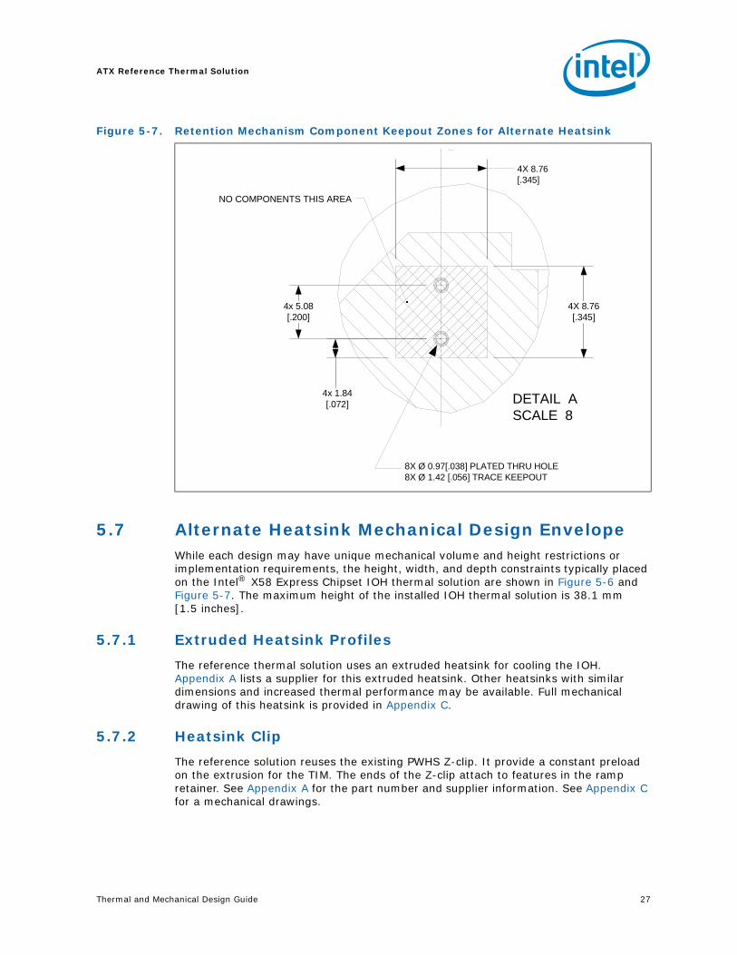
5.7 Alternate Heatsink Mechanical Design EnvelopeWhile each design may have unique mechanical volume and height restrictions or implementation requirements, the height, width, and depth constraints typically placed on the Intel® X58 Express Chipset IOH thermal solution are shown in Figure 5-6 and Figure 5-7. The maximum height of the installed IOH thermal solution is 38.1 mm [1.5 inches].
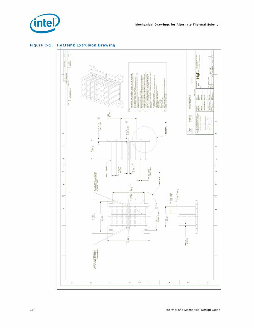
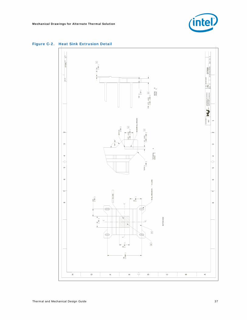
5.7.1 Extruded Heatsink Profiles
The reference thermal solution uses an extruded heatsink for cooling the IOH. Appendix A lists a supplier for this extruded heatsink. Other heatsinks with similar dimensions and increased thermal performance may be available. Full mechanical drawing of this heatsink is provided in Appendix C.
5.7.2 Heatsink Clip
The reference solution reuses the existing PWHS Z-clip. It provide a constant preload on the extrusion for the TIM. The ends of the Z-clip attach to features in the ramp retainer. See Appendix A for the part number and supplier information. See Appendix C for a mechanical drawings.
Figure 5-7. Retention Mechanism Component Keepout Zones for Alternate Heatsink
4X 8.76[.345]
4x 1.84[.072]
4x 5.08[.200]
NO COMPONENTS THIS AREA
DETAIL ASCALE 8
8X Ø 0.97[.038] PLATED THRU HOLE 8X Ø 1.42 [.056] TRACE KEEPOUT
4X 8.76[.345]

ATX Reference Thermal Solution
28 Thermal and Mechanical Design Guide
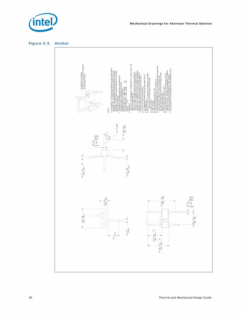
5.7.3 Anchor
For Intel® X58 Express Chipset based platforms the anchor from previous PWHS will be reused. By using anchors that are separate from the extrusion, the solderability of the anchors is improved. The elimination of the conduction path from pins in the extrusion reduces the chance for cold solder joints. This design incorporates a 45° bent leads to increase the anchor attach reliability over time. See Appendix A for the part number and supplier information. See Appendix C for a mechanical drawings.
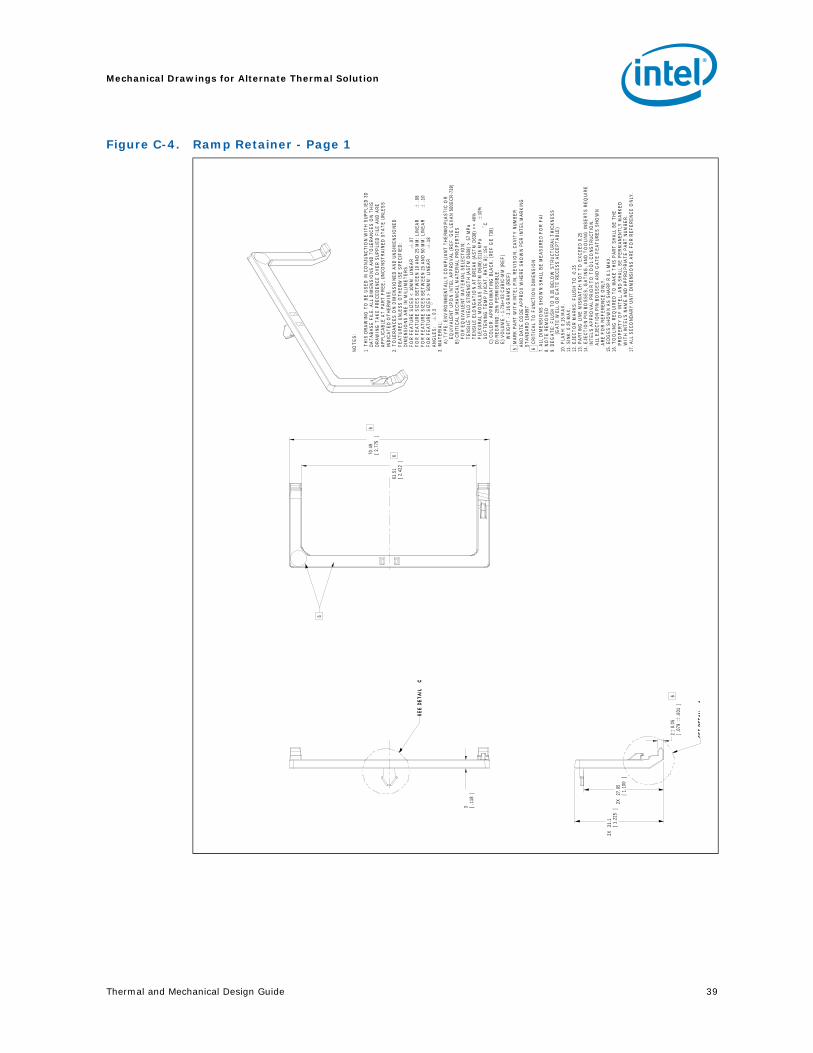
5.7.4 Ramp Retainer
The ramp retainer is a molded plastic component that is reused from previous PWHS designs. It is integral to the ability of the design to shift the shock and vibration loads away from the IOH solder joints. By assembling the heatsink extrusion, anchors and ramp retainer before wave solder the tolerances between the top of the IOH and the extrusion are absorbed as the board cools from the wave solder process.See Appendix A for the part number and supplier information. See Appendix C for a mechanical drawings.
5.7.5 Thermal Interface Material
A thermal interface material (TIM) provides conductivity between the IHS and heat sink. The reference thermal solution uses Honeywell PCM45 F*, 0.25 mm (0.010 in.) thick, 20 mm x 20 mm (0.79 in. x 0.79 in.) square.
§
Thermal and Mechanical Design Guide 29
Thermal Solution Component Suppliers
A Thermal Solution Component Suppliers
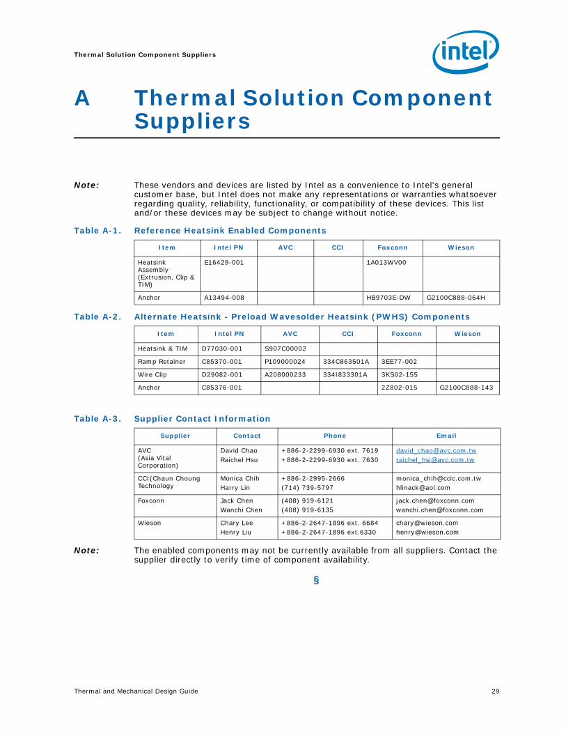
Note: These vendors and devices are listed by Intel as a convenience to Intel's general customer base, but Intel does not make any representations or warranties whatsoever regarding quality, reliability, functionality, or compatibility of these devices. This list and/or these devices may be subject to change without notice.
Note: The enabled components may not be currently available from all suppliers. Contact the supplier directly to verify time of component availability.
§
Table A-1. Reference Heatsink Enabled Components
Item Intel PN AVC CCI Foxconn Wieson
Heatsink Assembly (Extrusion, Clip & TIM)
E16429-001 1A013WV00
Anchor A13494-008 HB9703E-DW G2100C888-064H
Table A-2. Alternate Heatsink - Preload Wavesolder Heatsink (PWHS) Components
Item Intel PN AVC CCI Foxconn Wieson
Heatsink & TIM D77030-001 S907C00002
Ramp Retainer C85370-001 P109000024 334C863501A 3EE77-002
Wire Clip D29082-001 A208000233 334I833301A 3KS02-155
Anchor C85376-001 2Z802-015 G2100C888-143
Table A-3. Supplier Contact Information
Supplier Contact Phone Email
AVC (Asia Vital Corporation)
David ChaoRaichel Hsu
+886-2-2299-6930 ext. 7619+886-2-2299-6930 ext. 7630
[email protected][email protected]
CCI(Chaun Choung Technology
Monica ChihHarry Lin
+886-2-2995-2666(714) 739-5797
[email protected]@aol.com
Foxconn Jack ChenWanchi Chen
(408) 919-6121(408) 919-6135
[email protected]@foxconn.com
Wieson Chary LeeHenry Liu
+886-2-2647-1896 ext. 6684 +886-2-2647-1896 ext.6330
[email protected]@wieson.com

Thermal Solution Component Suppliers
30 Thermal and Mechanical Design Guide
Thermal and Mechanical Design Guide 31
Mechanical Drawings for Package & Reference Thermal Solution
B Mechanical Drawings for Package & Reference Thermal Solution
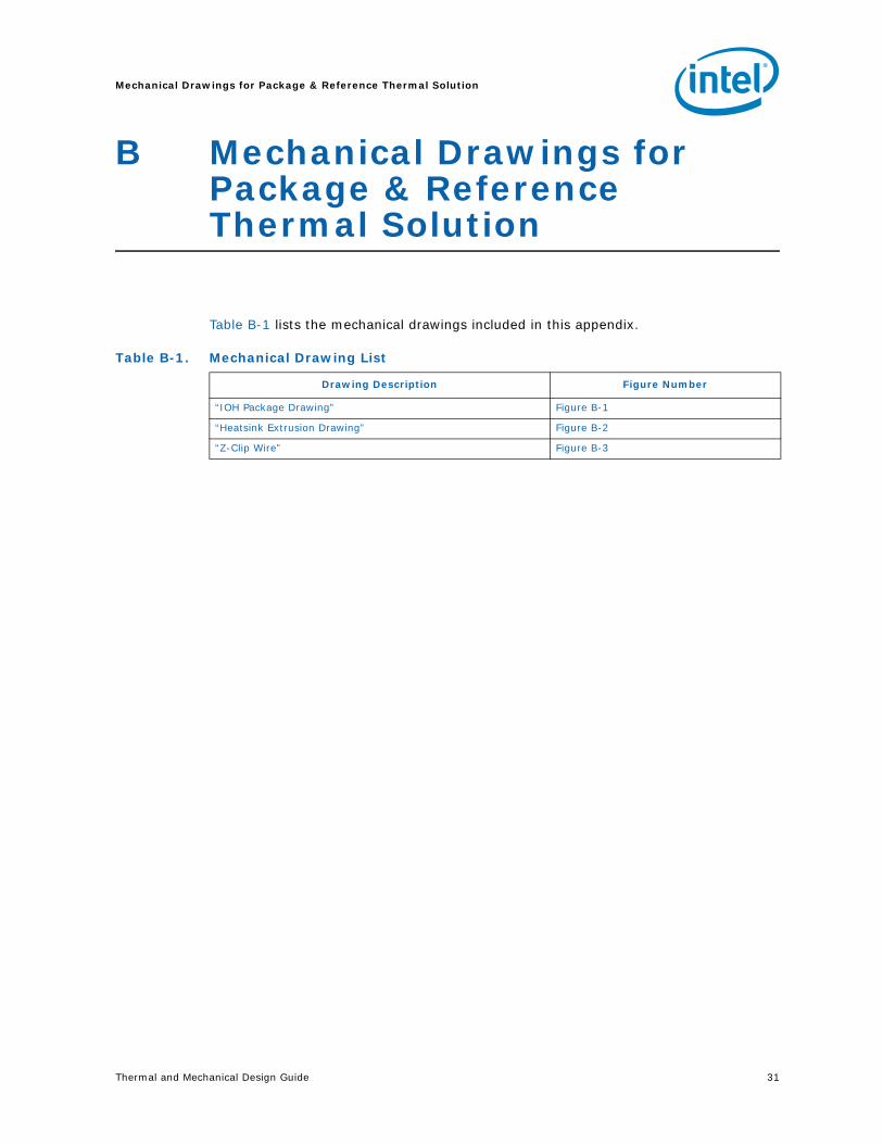
Table B-1 lists the mechanical drawings included in this appendix.
Table B-1. Mechanical Drawing List
Drawing Description Figure Number
“IOH Package Drawing” Figure B-1
“Heatsink Extrusion Drawing” Figure B-2
“Z-Clip Wire” Figure B-3
Mechanical Drawings for Package & Reference Thermal Solution
32 Thermal and Mechanical Design Guide
Figure B-1. IOH Package Drawing
Thermal and Mechanical Design Guide 33
Mechanical Drawings for Package & Reference Thermal Solution
Figure B-2. Heatsink Extrusion Drawing
A
B 44
[ 1.7
32
]
31
.3
[ 1.2
32 ]
15 x
1[0
.039
]
14 E
qual
Spa
ces
3.6
[1.4
2]
3
[ .11
8 ]
3 +
/-0
.2
[ .11
8 +/
- .00
753
.6[2
.110
]
.R 0
.3[ .
012
]
7[
,276
]
3 [ .
118
]
20
[.787
]
C
50.8
[2.0
0]
DE
PA
RT
ME
NT
R CO
RP
.
22
00
MIS
SIO
N C
OL
LE
GE
BL
VD
.P
.O.
BO
X 5
81
19
SA
NT
A C
LA
RA
, C
A 9
50
52-
81
19
TM
I
TIT
LE
BR
OA
DW
AT
ER
MC
H
BT
X H
EA
T S
INK
SIZ
E D
RA
WIN
G N
UM
BE
RR
EV
A1
D29
080
AS
CA
LE: 3
:1D
O N
OT
SC
AL
E D
RA
WIN
GS
HE
ET
1 O
F 1
SE
E N
OT
ES
SE
E N
OT
ES
FIN
ISH
MA
TE
RIA
L
09/0
6/0
5D
AT
EA
PP
RO
VE
D B
Y
09/0
6/0
509
/06
/05
DA
TE
CH
EC
KE
D B
Y08
/12
/05
DA
TE
DR
AW
N B
Y08
/08
/05
DA
TE
DE
SIG
NE
D B
YU
NL
ES
S O
TH
ER
WIS
E S
PE
CIF
IED
INT
ER
PR
ET
DIM
EN
SIO
NS
AN
D
TO
LE
RA
NC
ES
IN A
CC
OR
DA
NC
E W
ITH
AS
ME
Y1
4.5
M-
19
94
DIM
EN
SIO
NS
AR
E I
N M
ILL
IME
TE
RS
TH
IRD
AN
GL
E P
RO
JE
CT
ION
PAR
TS L
IST
DE
SC
RIP
TIO
NP
AR
T N
UM
BE
RIT
EM
NO
QT
Y
HT
SN
K,E
XT
D,F
BG
A,15
,AL
D29
080
-001
TO
P
DE
PA
RT
ME
NT
R CO
RP
.
22
00
MIS
SIO
N C
OL
LE
GE
BL
VD
.P
.O.
BO
X 5
81
19
SA
NT
A C
LA
RA
, C
A 9
50
52-
81
19
TM
I
TIT
LE
SIZ
E D
RA
WIN
G N
UM
BE
RR
EV
A1
D29
080
AS
CA
LE: 3
:1D
O N
OT
SC
AL
E D
RA
WIN
GS
HE
ET
1 O
F 1
SE
E N
OT
ES
SE
E N
OT
ES
FIN
ISH
MA
TE
RIA
L
DA
TE
AP
PR
OV
ED
BY
DA
TE
CH
EC
KE
D B
Y
DA
TE
DR
AW
N B
Y
DA
TE
DE
SIG
NE
D B
Y
TH
IRD
AN
GL
E P
RO
JE
CT
ION
PAR
TS L
IST
DE
SC
RIP
TIO
NP
AR
T N
UM
BE
RIT
EM
NO
QT
Y
HT
SN
K,E
XT
D,F
BG
A,15
,AL
D29
080
-001
TO
P
NO
TE
S:
1. T
HIS
DR
AW
ING
TO
BE
US
ED
IN C
ON
JUN
CT
ION
WIT
H S
UP
PLI
ED
3D
DA
TA
BA
SE
FIL
E. A
LL D
IME
NS
ION
S A
ND
TO
LER
AN
CE
S O
N T
HIS
D
RA
WIN
G T
AK
E P
RE
CE
DE
NC
E O
VE
R S
UP
PLI
ED
FIL
E A
ND
AR
E
A
PP
LIC
AB
LE A
T P
AR
T F
RE
E, U
NC
ON
ST
RA
INE
D S
TA
TE
UN
LES
S
IND
ICA
TE
D O
TH
ER
WIS
E.2.
TO
LER
AN
CE
S O
N D
IME
NS
ION
ED
AN
D U
ND
IME
NS
ION
ED
F
EA
TU
RE
S U
NLE
SS
OT
HE
RW
ISE
SP
EC
IFIE
D:
DIM
EN
SIO
NS
AR
E IN
MIL
LIM
ET
ER
S.
T
OLE
RA
NC
ES
:
LIN
EA
R ±
0.2
5
AN
GU
LAR
± 1
°3.
MA
TE
RIA
L: 6
063
-T5
ALU
MIN
UM
4. F
INIS
H: N
ON
E5
MA
RK
PA
RT
WIT
H IN
TE
L P/
N A
ND
RE
VIS
ION
AP
PR
OX
W
HE
RE
SH
OW
N P
ER
INT
EL
MA
RK
ING
ST
AN
DA
RD
1649
976
CR
ITIC
AL
TO
FU
NC
TIO
N D
IME
NS
ION
7. E
DG
ES
SH
OW
N A
S S
HA
RP
R 0.1
MA
X.
8. T
OO
LIN
G R
EQ
UIR
ED
TO
MA
KE
TH
IS P
AR
T S
HA
LL B
E T
HE
P
RO
PE
RT
Y O
F IN
TE
L, A
ND
SH
ALL
BE
PE
RM
AN
EN
TLY
MA
RK
ED
WIT
H IN
TE
L'S
NA
ME
AN
D A
PP
RO
PR
IAT
E P
AR
T N
UM
BE
R.9.
ALL
SE
CO
ND
AR
Y U
NIT
DIM
EN
SIO
NS
AR
E F
OR
RE
FE
RE
NC
E O
NLY
.10
. ALL
DIM
EN
SIO
NS
SH
OW
N S
HA
LL B
E M
EA
SU
RE
D F
OR
FA
I
11. R
EM
OV
E A
LL B
UR
RS
OR
SH
AR
P E
DG
ES
AR
OU
ND
PE
RIM
ET
ER
O
F P
AR
T. S
HA
RP
NE
SS
OF
ED
GE
S S
UB
JEC
T T
O H
AN
DLI
NG
AR
E
R
EQ
UIR
ED
TO
ME
ET
UL1
439
TE
ST.
12. A
PP
LY H
ON
EY
WE
LL T
IM P
CM
45F
(ST
D S
IZE
20M
M x
20
MM
) A
T
H
EA
T S
INK
BA
SE
WIT
H A
N A
SS
EM
BLY
PO
SIT
ION
AL
TO
LER
AN
CE
OF
±1.
0MM
TO
LER
AN
CE
15X
FU
LL R
OU
ND
R0
TO
FU
LL 0.1
[.003
] ∅
0.2
5 [.0
0]
BC
12 H
ON
EY
WE
LL
TIM
-PC
M45
F
3
20
[ .78
7 ]
6
Mechanical Drawings for Package & Reference Thermal Solution
34 Thermal and Mechanical Design Guide
§
Figure B-3. Z-Clip Wire
A
NO
TE
S:
1.
TH
IS D
RA
WIN
G T
O B
E U
SE
D IN
CO
RR
EL
AT
ION
WIT
H S
UP
PL
IED
3D
D
AT
AB
AS
E F
ILE
. AL
L D
IME
NS
ION
S A
ND
TO
LE
RA
NC
ES
ON
TH
IS
DR
AW
ING
TA
KE
PR
EC
ED
EN
CE
OV
ER
SU
PP
LIE
D F
ILE
AN
D A
RE
AP
PLI
CA
BL
E A
T P
AR
T F
RE
E, U
NC
ON
ST
RA
INE
D S
TA
TE
UN
LE
SS
IN
DIC
AT
ED
OT
HE
RW
ISE
.2.
TO
LER
AN
CE
S O
N D
IME
NS
ION
ED
AN
D U
ND
IME
NS
ION
ED
F
EA
TU
RE
S U
NL
ES
S O
TH
ER
WIS
E S
PE
CIF
IED
:
DIM
EN
SIO
NS
AR
E IN
MIL
LIM
ET
ER
S.
T
OLE
RA
NC
ES
: LIN
EA
R ±
0.2
5
AN
GL
ES
: ±
3°
3.
MA
TE
RIA
L:
TY
PE
: A
ST
M A
22
8 M
US
IC W
IRE
Ø1.
8 ±
0.1
MM
4
PL
AT
ING
: E
LE
CT
RO
-LE
SS
NIC
KE
L O
R E
QU
IVA
LE
NT
UP
ON
INT
EL
AP
PR
OV
AL
.4
CR
ITIC
AL
TO
FU
NC
TIO
N D
IME
NS
ION
5. M
AR
K W
ITH
INT
EL
P/N
AN
D R
EV
ISIO
N P
ER
INT
EL
MA
RK
ING
ST
AN
DA
RD
16
49
97;
PE
R S
EC
3.8
(P
OL
YE
TH
YL
EN
E B
AG
)6
. R
EM
OV
E A
LL
SH
AR
P E
DG
ES
AN
D B
UR
RS
.7.
ALL
DIM
EN
SIO
NS
SH
OW
N S
HA
LL B
E M
EA
SU
RE
D F
OR
FA
I8.
ALL
SE
CO
ND
AR
Y U
NIT
DIM
EN
SIO
NS
AR
E F
OR
RE
FE
RE
NC
E O
NLY
.
Thermal and Mechanical Design Guide 35
Mechanical Drawings for Alternate Thermal Solution
C Mechanical Drawings for Alternate Thermal Solution
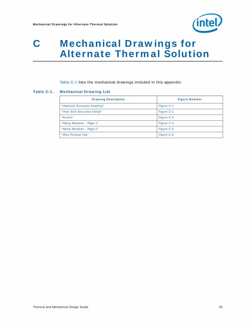
Table C-1 lists the mechanical drawings included in this appendix.
Table C-1. Mechanical Drawing List
Drawing Description Figure Number
“Heatsink Extrusion Drawing” Figure C-1
“Heat Sink Extrusion Detail” Figure C-2
“Anchor” Figure C-3
“Ramp Retainer - Page 1” Figure C-4
“Ramp Retainer - Page 2” Figure C-5
“Wire Preload Clip” Figure C-6
Mechanical Drawings for Alternate Thermal Solution
36 Thermal and Mechanical Design Guide
Figure C-1. Heatsink Extrusion Drawing
8
7
6
5
4
3
2
H G F E D C B A
8
7
6
5
4
3
2
1
2X
58.6 2.30
7[
]
471.
850
[]
2X
803.
150
[]
2X
3
480.
151.
890
.005
[]
2X
3
59.2
80.
152.
334
.005
[]
3
4.1
57[
]
30.5 1.20
1[
]
3
3.75
0.15
.148
.005
[]
35.5 1.39
8[
]
8X
1.
20.
15.0
47.0
05[
]
6X
EQ
UA
LS
PA
CIN
G
361.
417
[]
4X
EQ
UA
LSP
AC
ING
2X
2.7
0.15
.106
.005
[]
3X
7.46
0.15
.29
.00
[]
3
30.
15.1
18.0
05[
]
TH
IS D
RA
WIN
G C
ON
TAIN
S IN
TEL
CO
RP
OR
ATI
ON
CO
NFI
DE
NTI
AL IN
FOR
MA
TIO
N. I
T IS
DIS
CLO
SE
D IN
CO
NFI
DE
NC
E A
ND
ITS
CO
NTE
NTS
MA
Y N
OT
BE
DIS
CLO
SE
D, R
EP
RO
DU
CE
D, D
ISP
LAY
ED
OR
MO
DIF
IED
, WIT
HO
UT
THE
PR
IOR
WR
ITTE
N C
ON
SE
NT
OF
INTE
L C
OR
PO
RA
TIO
N.
REVI
SIO
N HI
STO
RYZO
NE
REV
DES
CR
IPTI
ON
DAT
EAP
PRO
A
INIT
IAL
RE
LEA
SE
09/0
8/06
-
D77
030
1D
WG
. NO
SHT.
RE
DE
PA
RT
ME
NT
R CO
RP
.
2200
MIS
SIO
N C
OLL
EGE
BLV
D.
P.O
. BO
X 58
119
SA
NTA
CLA
RA
, CA
950
52-8
119
PST
TIT
LE
HS, P
WSH
S, G
UARD
FISH
BW
, ATX
SIZE
DR
AWIN
G N
UM
BER
A1
D77
030
SCAL
E:
2D
O N
OT
SCAL
E D
RAW
ING
SHEE
T 1
OF
2SE
E N
OTE
SS
EE
NO
TES
FIN
ISH
MAT
ERIA
L
08/1
7/06
FRE
D A
ND
ER
SDA
TEAP
PRO
VED
BY
--
08/1
7/06
C B
ER
ME
NS
OLO
DATE
CH
ECKE
D B
Y
08/0
7/06
KG
TAN
DATE
DR
AWN
BY
08/0
7/06
KG
TAN
DATE
DES
IGN
ED B
YU
NLE
SS
OTH
ER
WIS
E S
PE
CIF
IED
INTE
RP
RE
T D
IME
NS
ION
S A
ND
TO
LER
AN
CES
IN A
CC
OR
DA
NC
E W
ITH
AS
ME
Y14
.5M
-199
4D
IME
NS
ION
S A
RE
IN M
ILLI
ME
TER
S
THIR
D A
NG
LE P
RO
JEC
TIO
N
PAR
TS L
IST
DE
SC
RIP
TIO
NP
AR
T N
UM
BE
RIT
EM N
OQ
TY
HS
NK
,EX
TD,F
BGA
,8,A
LD
7703
0-00
1TO
P
NOTE
S: 1
.TH
IS D
RAW
ING
TO
BE
USE
D IN
CO
NJU
NC
TIO
N W
ITH
TH
E S
UP
PLIE
D 3
D
DA
TAB
AS
E FI
LE. A
LL D
IME
NSI
ON
S A
ND
TO
LER
AN
CE
S O
N T
HIS
DR
AW
ING
TA
KE
PREC
ED
EN
CE
OVE
R S
UPP
LIE
D F
ILE
.
2.
ALL
SEC
ON
DAR
Y U
NIT
DIM
EN
SIO
NS
AR
E F
OR
RE
FER
ENC
E O
NLY
. TO
LER
AN
CES
SH
ALL
BE
CA
LCU
LATE
D F
RO
M P
RIM
AR
Y U
NIT
S TO
AV
OID
TR
UN
CAT
ION
ER
RO
RS
.
3
CR
ITIC
AL
TO F
UN
CTI
ON
DIM
ENSI
ON
4.
ANY
TOO
LIN
G D
ES
IGN
SH
ALL
BE
SUB
MIT
TED
TO
AN
D A
PPR
OVE
D B
Y IN
TEL
EN
GIN
EER
ING
PR
IOR
TO
CO
NS
TRU
CTI
ON
OF
THE
TO
OLS
.
5M
AR
K AS
SEM
BLY
WIT
H P
AR
T N
UM
BER
AN
D V
END
OR
IDEN
TIFI
CA
TIO
N
PER
INTE
L M
ARKI
NG
STA
ND
ARD
164
997
APP
RO
XIM
ATE
LY W
HE
RE
SH
OW
N.
6.
RE
MO
VE
ALL
BUR
RS
OR
SH
AR
P E
DG
ES
AR
OU
ND
PE
RIM
ETE
R O
F PA
RT.
BR
EAK
ALL
SH
ARP
CO
RN
ERS,
ED
GE
S, A
ND
BU
RR
S TO
0.1
0MM
MA
X.SH
ARP
NE
SS O
F E
DG
ES
SU
BJE
CT
TO H
AND
LIN
G A
RE
REQ
UIR
ED T
O M
EET
UL1
439
TES
T.
7.
MA
TER
IAL:
606
3-T5
ALU
MIN
UM
8.
UN
LESS
OTH
ERW
ISE
NO
TED
, TO
LER
ANC
ES
ON
DIM
EN
SIO
NED
AN
D
UN
DIM
EN
SIO
NE
D F
EAT
UR
ES
AR
E A
S FO
LLO
WS:
DIM
ENS
ION
S A
RE
IN M
ILLI
ME
TER
S.
TOLE
RA
NC
ES:
LIN
EAR
0
.25
ANG
ULA
R
1
9.
FIN
ISH
: CH
EMIC
AL E
TCH
10AP
PLY
HO
NE
YWE
LL T
IM P
CM
45F
(STD
SIZ
E 2
0mm
x 2
0mm
) AT
CE
NTE
R O
F H
EAT
SIN
K B
ASE
ALL
FIN
S IN
OU
TER
CO
LUM
NM
US
T B
E IN
LIN
E O
R C
ON
VE
X
TO M
IDD
LE F
INS
ALL
FIN
S IN
OU
TER
CO
LUM
NM
US
T B
E IN
LIN
E O
R C
ON
VE
X
TO M
IDD
LE F
INS
SEE
DE
TAIL
A
SE
E D
ETA
IL
B
8X F
ULL
RO
UN
D
SEE
DE
TAIL
A
SE
E D
ETA
IL
B
Thermal and Mechanical Design Guide 37
Mechanical Drawings for Alternate Thermal Solution
Figure C-2. Heat Sink Extrusion Detail
H G F E D C B A
8
7
6
5
4
3
2
8
7
6
5
4
3
2
1
662.
598
[]
23.9
06[
]
TYP
135
TYP
R1
.039
[]
3
1.5
0.15
.059
.005
[]
3
6.72
0.15
.265
.005
[]
4X R
0.5 .0
20[
]
TYP
3
2.75
0.15
.108
.005
[]
20.7
87[
]
20.7
87[
]
13.5 .532
[]
TYP
4.1
57[
]
2X
3
0.6 .0
24[
]
TH
IS D
RAW
ING
CO
NTA
INS
INTE
L C
OR
PO
RA
TIO
N C
ON
FID
ENTI
AL IN
FOR
MAT
ION
. IT
IS D
ISC
LOSE
D IN
CO
NFI
DEN
CE
AND
ITS
CO
NTE
NTS
MAY
NO
T BE
DIS
CLO
SED
, REP
RO
DU
CED
, DIS
PLAY
ED O
R M
OD
IFIE
D, W
ITH
OU
T TH
E P
RIO
R W
RIT
TEN
CO
NSE
NT
OF
INTE
L C
OR
POR
ATIO
N.
D77
030
2DW
G. N
OSH
T.RE
DE
PA
RT
ME
NT
R CO
RP
.
2200
MIS
SIO
N C
OLL
EGE
BLVD
.P.
O. B
OX
5811
9SA
NTA
CLA
RA,
CA
9505
2-81
19PS
T
SIZE
DR
AWIN
G N
UMBE
R
A1
D77
030
SCAL
E:
2DO
NO
T SC
ALE
DRAW
ING
SHEE
T 2
OF
2
BOTT
OM
VIE
W
54X
ALL
AR
OU
ND
45
X 1
[.03
9]
0.1
[.00]
10
TYP
DET
AIL
A
SCAL
E
5
NO
BU
RR
ALL
AR
OU
ND
DET
AIL
B
SCAL
E
5
Mechanical Drawings for Alternate Thermal Solution
38 Thermal and Mechanical Design Guide
Figure C-3. Anchor
6
5.21
0.12
.205
.004
[]
4X
6
7.83
0.12
.308
.004
[]
2X 1
0.13
0.12
.399
.004
[]
2X
6
0.77
0.1
.030
.003
[]
7.62
0.15
.300
.005
[]
2.5
0.15
.098
.005
[]
0.64
0 -0.0
7
.025
+.0
00-.
002
[]
6
5.08
0.12
.200
.004
[]
2X
3.94
0.15
.155
.005
[]
2X 4
52
2X
4 .157
[]
2X 0
.50.
05.0
20.0
01[
]2X
0.
75 .030
[]
0.64
0 -0.0
7
.025
+.0
00-.
002
[]
NO
TE
S:
1. T
HIS
DR
AW
ING
TO
BE
US
ED
IN
CO
NJU
NCT
ION
WIT
H S
UPP
LIE
D 3
D
DA
TA
BA
SE F
ILE
. A
LL D
IME
NS
ION
S A
ND
TO
LERA
NC
ES
ON
TH
IS
DR
AW
ING
TAK
E P
REC
ED
EN
CE
OV
ER
SU
PP
LIE
D F
ILE
AN
D A
RE
AP
PLI
CAB
LE A
T P
AR
T F
RE
E,
UNC
ON
ST
RAIN
ED
ST
AT
E U
NLE
SS
I
NDI
CA
TED
OT
HE
RW
ISE
.2.
TO
LERA
NC
ES
ON
DIM
EN
SIO
NE
D A
ND
UN
DIM
EN
SIO
NE
D
FE
AT
UR
ES U
NLE
SS
OTH
ER
WIS
E S
PE
CIF
IED:
D
IME
NS
ION
S A
RE
IN
MIL
LIM
ETE
RS
.
FO
R F
EA
TU
RE S
IZE
S <
10M
M:
LIN
EAR
.0
7
FO
R F
EA
TU
RE S
IZE
S >
10M
M:
LIN
EAR
.0
8
AN
GLE
S:
0.5
3. M
ATE
RIA
LS:
INS
ULA
TO
R:
PO
LYC
AR
BO
NA
TE
TH
ER
MO
PLA
ST
IC,
UL
94V
-0,
BLA
CK (
739)
(RE
F.
GE
LE
XA
N 3
412R
-739
)
C
ON
TAC
T:
BR
AS
S O
R E
QU
IVA
LEN
T U
PO
N I
NT
EL
AP
PR
OV
AL
C
ON
TAC
T F
INIS
H:
.000
050u
" M
IN. N
ICK
EL U
ND
ER
PLA
TIN
G;
SO
LDE
R T
AIL
S,
0.00
0100
" M
IN T
IN O
NLY
SO
LDE
R (
LEA
D F
RE
E).
5. M
ARK
WIT
H I
NT
EL
P/N
AN
D R
EV
ISIO
N P
ER
INT
EL
MA
RK
ING
ST
AN
DA
RD 1
6499
7; P
ER
SE
C 3
.8 (
PO
LYE
TH
YLE
NE
BA
G)
6 C
RIT
ICA
L TO
FU
NC
TIO
N D
IME
NS
ION
7. A
LL D
IMEN
SIO
NS
SHO
WN
SH
ALL
BE
ME
AS
UR
ED F
OR
FAI
8. N
OT
E R
EMO
VE
D9.
DE
GA
TE
: F
LUS
H T
O 0
.35
BELO
W S
TR
UCT
UR
AL
THI
CK
NES
S
(GA
TE
WE
LL O
R G
ATE
RE
CES
S A
CCE
PT
AB
LE)
10.
FLA
SH
: 0.
15 M
AX
.11
. S
INK
: 0.
25 M
AX
.12
. E
JEC
TO
R M
AR
KS
: F
LUS
H T
O -
0.25
13.
PA
RT
ING
LIN
E M
ISM
ATC
H N
OT
TO
EX
CE
ED
0.2
5.14
. E
JEC
TIO
N P
IN B
OSS
ES
, G
ATI
NG
, A
ND
TO
OLI
NG
IN
SER
TS
RE
QU
IRE
INT
EL'
S A
PP
RO
VA
L P
RIO
R T
O T
OO
L C
ON
ST
RU
CTI
ON.
A
LL E
JEC
TIO
N P
IN B
OS
SES
AN
D G
ATE
FE
ATU
RE
S S
HO
WN
ARE
FO
R R
EFE
RE
NC
E O
NLY
.15
. E
DG
ES S
HO
WN
AS
SH
AR
P R
0.1
MA
X.
16.
TO
OLI
NG
RE
QU
IRED
TO
MA
KE
TH
IS P
AR
T S
HA
LL B
E T
HE
PRO
PE
RT
Y O
F IN
TE
L, A
ND
SH
ALL
BE
PE
RM
AN
EN
TLY
MA
RK
ED
WIT
H I
NT
EL'
S N
AM
E A
ND
AP
PR
OP
RIA
TE
PAR
T N
UMB
ER
.17
. A
LL S
ECO
ND
AR
Y U
NIT
DIM
ENS
ION
S A
RE F
OR
REF
ER
EN
CE
ON
LY.
45 X
0.2
MIN
2X C
HA
MF
ER
ALL
ARO
UN
DC
ONT
AC
T T
O I
NS
ULA
TOR
IN
TE
RFA
CE
AT
SU
PP
LIE
RS
OP
TIO
N
Thermal and Mechanical Design Guide 39
Mechanical Drawings for Alternate Thermal Solution
Figure C-4. Ramp Retainer - Page 1
2X
31.1 1.
225
[]
6
20.
05.0
79.0
01[
]
661
.51
2.42
2[
]
6
70.4
92.
775
[]
2X
27.9
51.
100
[]
3.1
18[
]
NO
TE
S:
1. T
HIS
DR
AW
ING
TO
BE
US
ED
IN
CO
NJU
NC
TIO
N W
ITH
SU
PP
LIE
D 3
D
DA
TA
BA
SE
FIL
E.
ALL
DIM
EN
SIO
NS
AN
D T
OLE
RA
NC
ES
ON
TH
IS
DR
AW
ING
TA
KE
PR
EC
ED
EN
CE
OV
ER
SU
PP
LIE
D F
ILE
AN
D A
RE
AP
PLI
CA
BLE
AT
PA
RT
FR
EE
, U
NC
ON
ST
RA
INE
D S
TA
TE
UN
LES
S
IN
DIC
AT
ED
OT
HE
RW
ISE
.2.
TO
LER
AN
CE
S O
N D
IME
NS
ION
ED
AN
D U
ND
IME
NS
ION
ED
FE
AT
UR
ES
UN
LES
S O
TH
ER
WIS
E S
PE
CIF
IED
:
DIM
EN
SIO
NS
AR
E I
N M
ILLI
ME
TE
RS
.
FO
R F
EA
TU
RE
SIZ
ES
< 1
0MM
: LI
NE
AR
.0
7
FO
R F
EA
TU
RE
SIZ
ES
BE
TW
EE
N 1
0 A
ND
25
MM
: LI
NE
AR
.
08
FO
R F
EA
TU
RE
SIZ
ES
BE
TW
EE
N 2
5 A
ND
50
MM
: LI
NE
AR
.
10
FO
R F
EA
TU
RE
SIZ
ES
> 5
0MM
: LI
NE
AR
.1
8
AN
GLE
S:
0.5
3. M
AT
ER
IAL:
A
) T
YP
E:
EN
VIR
ON
ME
NT
ALL
Y C
OM
PLI
AN
T T
HE
RM
OP
LAS
TIC
OR
EQ
UIV
ALE
NT
UP
ON
IN
TE
L A
PP
RO
VA
L (R
EF
. G
E L
EX
AN
500
EC
R-7
39)
B)
CR
ITIC
AL
ME
CH
AN
ICA
L M
AT
ER
IAL
PR
OP
ER
TIE
S
F
OR
EQ
UIV
ALE
NT
MA
TE
RIA
L S
ELE
CT
ION
:
T
EN
SIL
E Y
IELD
ST
RE
NG
TH
(A
ST
M D
638)
> 5
7 M
Pa
TE
NS
ILE
ELO
NG
AT
ION
AT
BR
EA
K (
AS
TM
D63
8) >
= 4
6%
F
LEX
UR
AL
MO
DU
LUS
(A
ST
M D
638)
311
6 M
Pa
10%
S
OF
TE
NIN
G T
EM
P (
VIC
AT
, R
AT
E B
): 1
54C
C
) C
OLO
R:
AP
PR
OX
IMA
TIN
G B
LAC
K,
(RE
F G
E 7
39)
D)
RE
GR
IND
: 25
% P
ER
MIS
SIB
LE.
E)
VO
LUM
E -
1.7
3e+
03 C
UB
IC-M
M (
RE
F)
WE
IGH
T -
2.1
6 G
RA
MS
(R
EF
)
5 M
AR
K P
AR
T W
ITH
IN
TE
L P
/N,
RE
VIS
ION
, C
AV
ITY
NU
MB
ER
A
ND
DA
TE
CO
DE
AP
PR
OX
WH
ER
E S
HO
WN
PE
R I
NT
EL
MA
RK
ING
ST
AN
DA
RD
164
997
6 C
RIT
ICA
L T
O F
UN
CT
ION
DIM
EN
SIO
N
7. A
LL D
IME
NS
ION
S S
HO
WN
SH
ALL
BE
ME
AS
UR
ED
FO
R F
AI
8. N
OT
E R
EM
OV
ED
9. D
EG
AT
E:
FLU
SH
TO
0.3
5 B
ELO
W S
TR
UC
TU
RA
L T
HIC
KN
ES
S
(G
AT
E W
ELL
OR
GA
TE
RE
CE
SS
AC
CE
PT
AB
LE)
10.
FLA
SH
: 0.
15 M
AX
.11
. S
INK
: 0.
25 M
AX
.12
. E
JEC
TO
R M
AR
KS
: F
LUS
H T
O -
0.25
13.
PA
RT
ING
LIN
E M
ISM
AT
CH
NO
T T
O E
XC
EE
D 0
.25.
14.
EJE
CT
ION
PIN
BO
SS
ES
, G
AT
ING
, A
ND
TO
OLI
NG
IN
SE
RT
S R
EQ
UIR
E
IN
TE
L'S
AP
PR
OV
AL
PR
IOR
TO
TO
OL
CO
NS
TR
UC
TIO
N.
A
LL E
JEC
TIO
N P
IN B
OS
SE
S A
ND
GA
TE
FE
AT
UR
ES
SH
OW
N
A
RE
FO
R R
EF
ER
EN
CE
ON
LY.
15.
ED
GE
S S
HO
WN
AS
SH
AR
P R
0.1
MA
X.
16.
TO
OLI
NG
RE
QU
IRE
D T
O M
AK
E T
HIS
PA
RT
SH
ALL
BE
TH
E
P
RO
PE
RT
Y O
F I
NT
EL,
AN
D S
HA
LL B
E P
ER
MA
NE
NT
LY M
AR
KE
D
W
ITH
IN
TE
L'S
NA
ME
AN
D A
PP
RO
PR
IAT
E P
AR
T N
UM
BE
R.
17.
ALL
SE
CO
ND
AR
Y U
NIT
DIM
EN
SIO
NS
AR
E F
OR
RE
FE
RE
NC
E O
NLY
.
SE
E D
ET
AIL
C
5
SE
ED
ET
AIL
AS
EE
DE
TA
ILA
SE
E D
ET
AIL
C
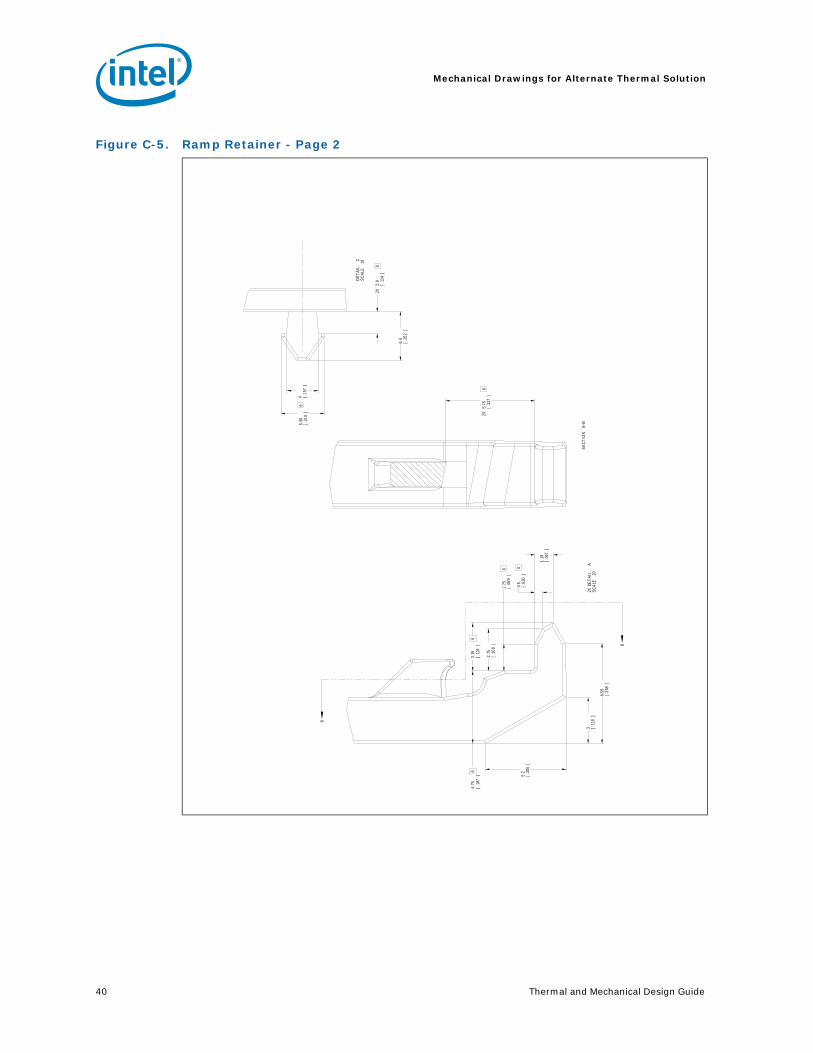
Mechanical Drawings for Alternate Thermal Solution
40 Thermal and Mechanical Design Guide
Figure C-5. Ramp Retainer - Page 2
B
B
6
1.75 .0
69[
]
2.75 .1
08[
]
6
0.5 .0
20[
]
4 .157
[]
6
5.56 .2
19[
]
2X
6
2.9 .1
14[
]
6.4 .2
52[
]
6
3.15 .1
24[
]6
4.75 .1
87[
]
3 .118
[]
5.2 .2
05[
]
1.19 .0
47[
]
6.55 .2
58[
]
2X
6
5.76 .2
27[
]
2X D
ET
AIL
A
SC
ALE
20
DE
TA
IL
CS
CA
LE
10
SE
CTIO
N
B-B
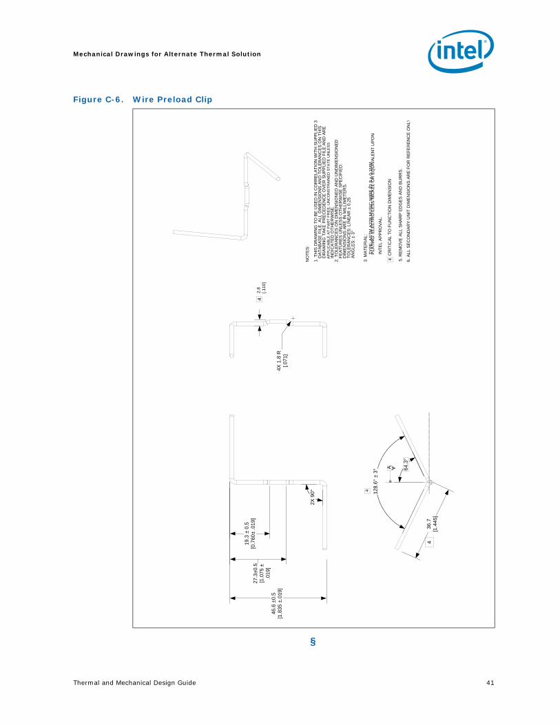
Thermal and Mechanical Design Guide 41
Mechanical Drawings for Alternate Thermal Solution
§
Figure C-6. Wire Preload Clip
A
46.6
±0.
5[1
.835
±.0
19]
19.3
± 0
.5[0
.760
± .0
19]
27.3
±0.5
[1.0
75
± .0
19]
2X 9
0°
4X 1
.8 R
[.0
71]
36.7
[1.4
45]
128
.6°
± 3° 64
.3°
NO
TE
S:
1. T
HIS
DR
AW
ING
TO
BE
US
ED
IN
CO
RR
ELA
TIO
N W
ITH
SU
PP
LIE
D 3
D
AT
AB
AS
E F
ILE
. ALL
DIM
EN
SIO
NS
AN
D T
OLE
RA
NC
ES
ON
TH
IS
DR
AW
ING
TA
KE
PR
EC
ED
EN
CE
OV
ER
SU
PP
LIE
D F
ILE
AN
D A
RE
AP
PLI
CA
BLE
AT
PA
RT
FR
EE
, U
NC
ON
ST
RA
INE
D S
TA
TE
UN
LES
S
IN
DIC
AT
ED
OT
HE
RW
ISE
.2.
TO
LER
AN
CE
S O
N D
IME
NS
ION
ED
AN
D U
ND
IME
NS
ION
ED
F
EA
TU
RE
S U
NLE
SS
OT
HE
RW
ISE
SP
EC
IFIE
D:
D
IME
NS
ION
S A
RE
IN
MIL
LIM
ET
ER
S.
T
OLE
RA
NC
ES
: LIN
EA
R ±
0.2
5
AN
GLE
S: ±
3°
3. M
AT
ER
IAL
:
TY
PE
: AS
TM
A22
8 M
US
IC W
IRE
Ø1.
8 ±
0.1M
M
4
PLA
TIN
G: E
LEC
TR
O-L
ES
S N
ICK
EL
OR
EQ
UIV
ALE
NT
UP
ON
IN
TE
L A
PP
RO
VA
L.
4 C
RIT
ICA
L T
O F
UN
CT
ION
DIM
EN
SIO
N
5. R
EM
OV
E A
LL S
HA
RP
ED
GE
S A
ND
BU
RR
S.
2.8
[.110
]
6. A
LL S
EC
ON
DA
RY
UN
IT D
IME
NS
ION
S A
RE
FO
R R
EF
ER
EN
CE
ON
LY
4
A
4

Mechanical Drawings for Alternate Thermal Solution
42 Thermal and Mechanical Design Guide