thermal and structural analyses of …/67531/metadc620575/...thermal and structural analyses of...
TRANSCRIPT

.
THERMAL AND STRUCTURAL ANALYSES OF VARIABLE THICKNESS PLANE PROBLEMS
Zhibi Wang
Experimental Facilities Division Argonne National Laboratory
Argonne, IL
Tuncer M. Kuzay
Experimental Facilities Division Argonne National Laboratory
Argonne, IL
ABSTRACT Finite difference formulations for variable thickness thermal
analysis and variable thickness plane stress analysis are presented. In heat transfer analysis, radiation effects and temperature-dependent thermal conductivity are taken into account. While in thermal stress analysis, the thermal expansion coefficient is considered as temperature dependent. An
' application of the variable thickness window for synchrotron radiation beamline under very strong X-ray is provided.
I NTRO D UCTlO N A concept that uses a variable thickness window for a
synchrotron radiation beamliie has been proposed [l] for thud- generation synchrotron x-ray facilities that can generate a very bright x-ray beam in a very small area. The main advantages of using a variable thickness window are as follows: (1) to make it possible to design a window without filters and therefore make more low energy photons available to the users; (2) to increase the heat conduction area without increasing the thickness in core area so that the maximum temperature in the window can be significantly decreased; (3) to increase the safety margin of window system due to the increasing structural integrity, especially in regards to the buckling load in thin windows, which also increases the structural integrity of window against shock due to sudden loss of vacuum: and (4) to increase the window size under the same operating conditions. Compared to a uniform Be window, the variable thickness Be window reduces the likelihood of the catastrophic break.
Because windows usually have a regular geometry, such as rectangular or circular forms, the finite difference method is the
best fit for their analyses. Finite difference formulation with temperature-dependent material properties are used for variable thickness plane thermal and plane stress problems. Because radiative cooling dominates when the temperature is high, the radiation effect has been considered.
In this paper, the fmite difference formulations for variable thickness thermal analysis and variable thickness plane stress analysis are presented. In heat transfer analysis, radiation effects and temperature-dependent thermal conductivity are taken into account. 'While in thermal stress analysis, the thermal expansion coefficient is considered as temperature dependent. An application of the variable thickness window to an Advanced Photon Source beamline is presented.
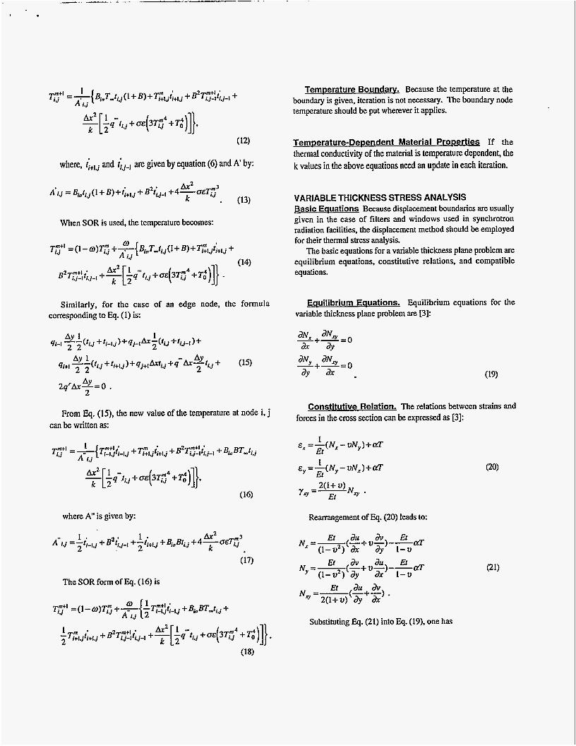
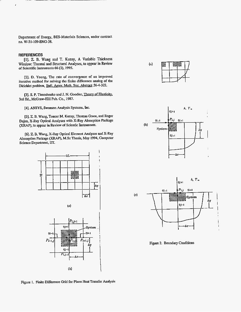
VARIABLE THICKNESS THERMAL ANALYSIS Finite Difference Formulation Assuming a domain of size a by b is divided into a mesh (as shown in figure 1) in which Ax and Ay are the sizes of the grid in the x and y directions, respectively, one can apply the first law of thermodynamics to a nodal point i, j in figure 1 @):
where qg1. qj-1, qi+l, q j+ l and q'can be related to temperature by F15uriex's law id conduction and Stefan-Boltzmann law in radiation:

DISCLAIMER
This report was prepared as an account of work sponsored by an agency of the United States Government. Neither the United States Government nor any agency thereof, nor any of their employees, make any warranty, express or implied, or assumes any legal liability or responsibility for the accuracy, completeness, or usefulness of any information, apparatus, product, or process disclosed, or represents that its use would not infringe privately owned rights. Reference herein to any specific commercial product, process, or service by trade name, trademark, manufacturer, or otherwise does not necessarily constitute or imply its endorsement, recommendation, or favoring by the United States Government or any agency thereof. The views and opinions of authors expressed herein do not necessarily state or reflect those of the United States Government or any agency thereof.

DISCLAIMER
Portions of this document may be illegible in electronic image products. Images are produced from the best available original document.

Radiation is taken into account by qr for a unit area. In equation (I ) , the factor of 2 accounts for the top and bottom sulfdces.
Inserting Eq. (2) into Eq. (1) and letting B= M A Y , one has
(3) (9)
The o denotes the relaxation factor. If o =1, the SOR method reduces to the classical GaussSeidel method. With a relaxation factor o I w S 2 , the convergence can be guaranteed [Z].
This is the standard finite difference formulation for a planar heat conduction problem that can be found in almost any finite difference text book. The finite difference formulation based on Eq. (5) is a direct iteration method. For computers, an effective method for obtaining a numerical solution is called the successive over-relaxation method (SOR) [2]. If the SOR method is used, the new value at node i, j can be calculated as:
For an iterative solution, if m denotes the iteration number, one can use the following approximation:
(4)
Substituting Eq. (4) into Eq (3), an expression for T Y can be derived as:
(5)
and
In the case of a uniform thickness, without radiation effects and for Ax = Ay, all variables in Eq. (6) become the same and equal to ti j . Quation (5) then becomes:
Boundarv Conditions Two boundary conditions have been investigated a convective b o u n d q and a constant temperature boundary.
Convection Boundarv. As shown in figures 2@) and 2(c), the temperature at a comer node and that at an edge node should be derived separately.
For the case in figure 2(b), the following equation can be derived from the first law of thermodynamics:
where
By assuming that Bio = hAx/k, the temperature in a comer node can be expressed as:
where, ti,,,] and tij-, are given by equation (6) and A' by:
Ax2 A'lJ = Bioti,j(l+ B)+tit,,j + Bzt&l +~-oET;' k - (13)
When SOR is used, the temperature becomes:
Similarly, for the case of an edge node, the formula corresponding to Eq. (1) is:
2q'Ax-=O AY . 2
From Eq. (15), the new value of the temperature at node i, j can be written as:
where A" is given by:
The SOR form of Eq. (16) is
TemDerature Boundarv. Because the temperature at the boundary is given, iteration is not necessary. The boundary node temperature should be put wherever it applies.
TernDerature-Dependent Material Propert ies If the thermal conductivity of the material is temperature dependent, the k values in the above equations need an update in each iteration.
VARIABLE THICKNESS STRESS ANALYSIS Basic Eauations Because displacement boundaries are usually given in the case of filters and windows used in synchrotron radiation facilities, the displacement method should be employed for their thermal stress analysis.
The basic equations for a variable thickness plane problem are equilibrium equations, constitutive relations, and compatible equations.
Eauilibrium Equations. Equilibrium equations for the variable thickness plane problem are [3]:
Constitutive Relation. The relations between strains and forces in the cross section can be expressed as t31:
E, = - ( N , - v N , ) + a T 1
Y, = 7 N , -
Et
E y =- 1 ( Ny - vN, ) + cfl Et 2 ( l + v )
Rearrangement of Eq. (20) leads to:
Et du & Et aT
Et & du Et
Nx=-( -+V-) - - (1-v2) dx a y 1 - 2 ,
(1-v2) a y ax 1-v Ny =-(-+u-)--df
Et du & N =- (-+-) . 2 ( l + v ) ay ax
Substituting Eq. (21) into Eq. (19). one has
a Et au av Et -[-(-+ u-)---crT]+ ax ( I - ~ ax ay I -u a EI au av -[-(-+-)]=O ay 2(1+u) ay ax
m+ av au Et ay ( 1 - u ~ ) ay ax 1 - u
a Et au aV -[-(-+-)I = 0. ax 2(1+u) ay ax
--[- a Et ( - +u-)--
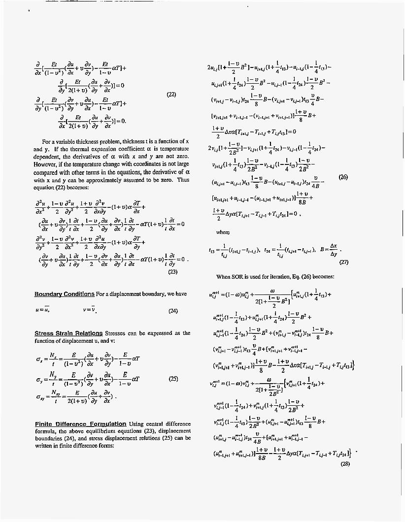
For a variable thickness problem, thickness t is a function of x and y. If the thermal expansion coefficient 0: is temperature dependent, the derivatives of a with x and y are not zero. However, if the temperature change with coordinates is not large compared with other terms in the equations, the derivative of 01 with x and y can be approximately assumed to be zero. Thus equation (22) becomes:
2% I - v aZu i + ~ dZv (l+u)a-+ a
azv I -u aZv I + U a2u (l+u)a-+ aT
- +--+--- ax2 2 ay2 2 axaY ax (-+ u-)--+-(-+-)--- crT(L+ u)--= 0
ay2 2 ax2 2 axay JY
(-+ u-)--+-(-+-)---clT(l+U)--=O .
au av I at I-v au aV t a t 1 at ax ay t ax 2 ay ax t ay t ax
- +--+--- m, au iat 1-u m, au i a t 1 at ay ax t ay 2 ax ay t a x 1 JY
Boundarv Conditions For a displacement boundary, we have
Stress Strain Relations Stresses can be expressed as the function of displacement u, and v:
oy=-=-(-+u-)--ctT N~ E dv au E f (1-uZ) ay ax I-u
Finite Difference Formulation Using central difference formula, the above equilibrium equations (23), displacement boundaries (24), and stress displacement relations (25) can be written in finite difference forms:
where
1 1 Ax AY ti. j ti. j
t13 =-(t. . - t . .) 2, =-(t.. --.. ), B=- . l + l J 1-1.1 9 lJ+I y - l
(27)
When SOR is used for iteration, Eq. (26) becomes:
C
The boundary conditions are:
After the convergence, one can calculate the stresses by the following stress- displacement relation:
( 0 x ) j . j =
BENCHMARKS To make sure that the algorithm derived here is correct,
benchmarks have been conducted and results are compared with those from the finite element code ANSYS [3].
Thermal Analvsis of Uniform Thickness Filters The thermal analysis of a filter subjected to an x-ray heat load has been performed and compared with the finite element code ANSYS. The difference with the ANSYS analysis is within 1%.
Thermal Analvsis of Variable Thickness Filters The second benchmark problem is a variable thickness filter subjected to an x-ray heat load with a temperature boundary condition. Comparison with the ANSYS result is also indistinguishable.
Radiation Effect A similar problem has been analyzed taking into consideration the radiation effect The difference is still very small.
Benchmarks for thermal stress were also conducted, and the results are compared with those from the finite element code ANSYS. The thermal stress analysis of a filter subjected to an x- ray heat load has been analyzed with the finite element code ANSYS. The result here obtained with the finite difference method is consistent with ANSYS.
APPLICATIONS The behavior of a window can be improved by using variable
thickness. One example is variable thickness windows for the SRI CAT undulator. It is assumed that the temperature of the block-holding filter and the window is kept at 300 K. The thermal conductivity of both graphite and Be material is 2 W/cm
K. The radiation effect is taken into account with the emissivity of 0.2 for both the Be and graphite materials.
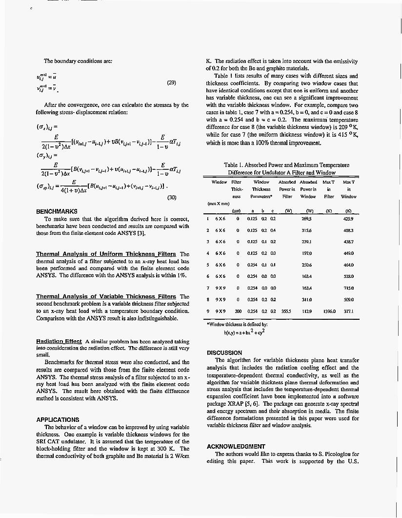
Table 1 lists results of many cases with different sizes and thickness coefficients. By comparing two window cases that have identical conditions except that one is uniform and another has variable thickness, one can see a significant improvement with the variable thickness window. For example, compare two cases in table 1. case 7 with a = 0.254. b = 0, and c = 0 and case 8 with a = 0.254 and b = c = 0.2. The maximum' temperature difference for case 8 (the variable thickness window) is 209 OK,
while for case 7 (the uniform thickness window) it is 415 OK, which is more than a 100% thermal improvement.
Table 1. Absorbed Power and Maximum Temperature Difference for Undulator A Filter and Window
Window Film Window Absorbed Absorbed MaxT MaxT Thick- Thickness Powcrin Powerin in in ncs Paramcfus* Film Window Filter Window
(mm X mm) (lun) a b c or3 0 00 (K)
I 6 x 6 0 0.125 02 02 2695 425.9
2 6 x 6 0 0.125 02 0.4 3 15.6 4053
3 6 x 6 0 0.125 QI 02 239.1 4387
4 6 x 6 0 0.125 02 01) 197.0 449.0
5 6 x 6 0 0254 Q1 Q1 250.6 464.0
6 6 x 6 0 0254 0.001) 163.4 528.0
7 9 x 9 o om ao 0.0 163.4 715.0
8 9 x 9 0 0254 0202 311.0 M9.0
9 9 x 9 200 0 x 4 02 02 3555 1129 1396.0 3n.1
*Window thickness i s defined by: h(x,y) =a+ bx2 +cy2
DISCUSSION The algorithm for variable thickness plane heat transfer
analysis that includes the radiation cooling effect and the temperature-dependent thermal conductivity, as well as the algorithm for variable thickness plane thermal deformation and stress analysis that includes the temperaturedependent thermal expansion coefficient have been implemented into a software package XRAP [5; 61. The package can generate x-ray spectral and energy spectrum and their absorption in media. The finite difference formulations presented in this paper were used for variable thickness filter and window analysis.
ACKNOWLEDGMENT
editing this paper. The authors would like to express thanks to S. Picologlou for
This work is supported by the U.S.
Department of Energy, BES-Materials Sciences. under contract no. W-3 1-109-ENG-38.
REFERENCES [l]. Z. B. Wang and T. Kuzay, A Variable Thickness
Window: Thermal and Structural Analyses, to appear in Review of Scientific Instrumcnt.. 66 (2). 1995.
[2]. D. Young, The rate of convergence of an improved iterative method for solving the finite difference analog of the Dirichlet problem, Bull. Amer. Math. SOC. Abstract 564322.
[3]. S. P. Timoshenko and J. N. Goodier. Theorv of Elasticitv, 3rd Ed., McGraw-Hill Pub. Co., 1987.
[4]. ANSYS, Swanson Analysis Systems. Inc.
[5]. Z. B. Wang, Tuncer M. Kuzay, Thomas Grace, and Roger Dejus, X-Ray Optical Analyses with X-Ray Absorption Package (XRAP), to appear in Review of Scientic Ihstruments.
161. Z. B. Wang, X-Ray Optical Element Analyses and X-Ray Absorption Package (XRAP), M.Sc Thesis, May 1994, Computer Science Department, IIT.
Figure 2. Boundary Conditions
Figure 1. Finite Difference Grid for Plane Heat Transfer Analysis