thermal barrier coatings on laser surface modified aisi...
TRANSCRIPT
Thermal barrier coatings on laser surface modified AISI H13 tool steel
using Atmospheric Plasma Spray Technique
M. S. Reza1, a, S. N. Aqida1, b,Mohd Radzi Mohd Toff2, c and D.
Brabazon3, d
1Faculty of Mechanical Engineering, Universiti Malaysia Pahang, 26600 Pekan, Pahang,
Malaysia
2Advanced Materials Research Centre, Sirim Berhad, Lot 34, Jalan Hi-Tech 2/3, KULIM HI-
TECH PART, 09000 Kulim, Kedah, Malaysia
3Advanced Processing Technology Research Centre, Dublin City University, Dublin 9, Ireland
[email protected], [email protected], [email protected], [email protected]
Keywords: AISI H13 steels, thermal barrier coatings, Yttria Stabilized Zirconia, NiCrAlY,
Abstract: This paper presents yttria-stabilized zirconia (YSZ) coating deposition on laser surface
modified H13 tool steel using atmospheric plasma spray (APS) technique. A Praxair Plasma
Spray System with SG-100 gun was used to deposit coating materials on laser-modified H13 tool
steel substrate surface. A bond coat layer material was NiCrAlY alloy while the top coat was
yttria stabilized zirconia (YSZ) with powder size distribution range of -106 µm to +45 µm. A 23
design of experiment (DOE) was used to deposit bond coat and top coat powders with three
controlled factors of input current, powder feed rate and stand-off-distance. The design was
optimised for minimum porosity and maximum hardness. The coating thickness and percentage
of porosity were measured using IM7000 inverted optical microscope. Hardness properties of
top coating layer were measured by using MMT-X7 Matsuzawa Hardness Tester Machine with
vickers hardness scale. The microscopy findings indicated variations of coating thickness at
different parameters settings. Samples at the highest current and powder feed rate and lowest
stand-off distance settings produced a lower porosity percentage and higher hardness. A higher
powder feed rate with the smallest stand-off-distance allowed melted powders to travel
uniformly onto the substrate surface. These findings were significant to development of thermal
barrier coatings on semi-solid forming die surface.
Introduction
In forming applications, die surface was rapidly heated during molten metal injection, and was
cooled by water quenching during solidification [1]. Repetitive cycles of these processes initiated
premature failure in dies such as thermal fatigue (heat checking), erosion, corrosion, local
adherence of the casting alloy to the tool (soldering) and gross fracture [2, 3, 4]. Erosion is
physical impingement of incoming liquid and partially solid alloy onto die surface.
Thermal spray processes like flame spray, electric arc spray, and plasma arc spray have been
used to deposit metallic or non-metallic coatings [5, 6]. For thermal barrier coating application,
YSZ in powder form was heated to a molten state or semi molten state and was projected in the
form of micrometer size particles at high speed onto substrate surface using atmospheric plasma
spray. Coating quality was determined by its porosity content and hardness properties [7, 8].
Though much works have been conducted on porosity study in thermal spray coatings, and
effects of micro-cracks and pores on coating properties, limited works reported on atmospheric
plasma spray parameters effects on porosity content in YSZ coating [9, 10-13].
Several attempts have been carried out to establish relationship of thermal spray coating process
parameters such as Taguchi method, full and fractional DOE [14,15]. A full factorial design
with three factors and two levels was reported to determine the dependence of photocatalytic
activity of titania coatings on plasma power, carrier gas flow rate, and powder feed rate [16].
Generally, both hardness and porosity content were related where coating with high content
porosity produced varied hardness properties [17]. Excessive porosity content influenced
structural integrity of coating. During plasma spraying process, pores can be generated from
entrapped gases, incomplete filling and shrinking during rapid solidification of splats. Major
problems in plasma sprayed coatings were presence of open pores, closed pores and micro-
cracks which reduced mechanical properties of coating such as elastic modulus, micro-hardness
and bonding strength [18]. Porosity varied from 2% to more than 20% which dependent to spray
parameters. Changes of spray parameters influenced particle velocity and temperature which
were closely linked to coating hardness and porosity content [14]. The porosity of plasma-
sprayed coatings was analysed using digital image analysis [19]. In this study, experimental
techniques have been utilised to study erosion failure mechanism that related to the coating
density. Low erosion failure may occur with low porosity and high hardness obtained.
Methodology and materials
AISI H13 steel was used as substrate material and chemical composition of the substrate
materials is given in Table 1. Bond coat powder used was Praxair Nickel based NiCrAlY (Ni-
164/211 Ni 22%Cr 10%Al 1.0%Y) while top coat, Praxair Ai-1075 ceramic coating yttria
stabilized zirconia (ZrO2 + 8 wt.% Y2O3).
Samples of 10 mm diameter and 150 mm length were processed using CO2 laser system with
range of treated surface thickness of 10 to 32 μm. Details of processing was as described
elsewhere [ref]. The laser modified sample was coated using APS method with parameters given
in Table 2. Sample was rotated by controllable speed chuck during deposition and was
positioned at a stand-off distance perpendicular to robotic arm which held plasma spray gun. The
robotic arm was translated in z-direction to deposit the entire sample surface. In Table 2, bond
coat was deposited at constant feed rate, stand-off distance and current while top coat processing
was conducted at 23 design of experiment. The parameters settings for 2
3 DOE is shown in Table
3.
Metallographic study was conducted using IM7000 inverted optical microscope. Samples were
measured for hardness using MMT-X7 Matsuzawa Hardness Tester Machine with vickers
hardness scale while porosity content was analysed using ImageJ software.
Table 1: Chemical composition of AISI H13 steel (wt. %)
Material C Mn Si Cr Ni Mo V Cu P S Fe
H13 0.32-
0.45
0.20-
0.50
0.80-
1.20
4.75-
5.50 0.30
1.10-
1.75
0.80-
1.20 0.25 0.03 0.03 Bal.
Table 2: Praxair plasma spray system parameter settings
Parameters Unit Bond coat (NiCrAlY)
setting
Top coat (YSZ)
setting
Secondary gas (He) kPa 345 827
Primary gas (Ar) kPa 345 345
Carrier gas (Ar) kPa 345 207
Workpiece rotational speed rpm 250 250
No. of cycle no. 4 22
Torch speed % 5 5
Input Current
Feed Rate
Ampere
g/min
550
29.8
550
36.3
650
51.7
Stand-off distance mm 110 100 120
Table 3: DOE 23 level parameter settings
Sample
no. Current, A Feed rate, g/min
Stand-off distance,
mm
1 550 51.7 120
2 650 36.3 120
3 650 36.3 100
4 550 51.7 100
5 650 51.7 100
6 550 36.3 120
7 550 36.3 100
8 650 51.7 120
Results and discussions
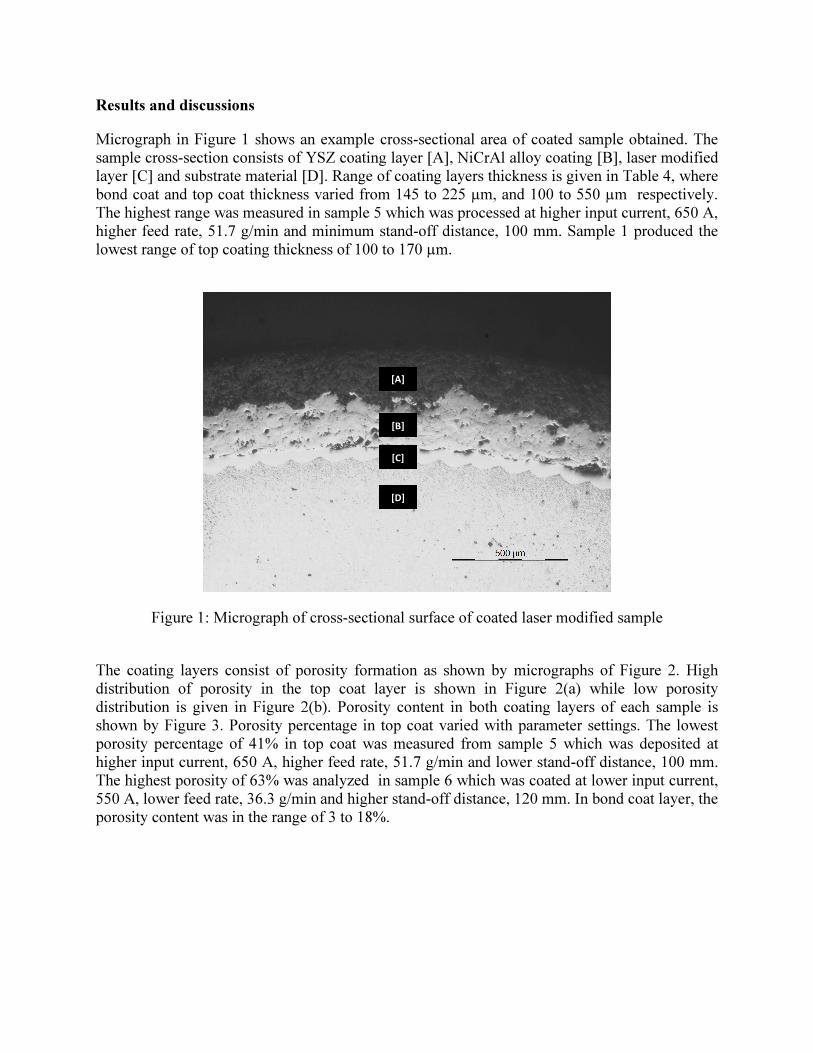
Micrograph in Figure 1 shows an example cross-sectional area of coated sample obtained. The
sample cross-section consists of YSZ coating layer [A], NiCrAl alloy coating [B], laser modified
layer [C] and substrate material [D]. Range of coating layers thickness is given in Table 4, where
bond coat and top coat thickness varied from 145 to 225 µm, and 100 to 550 µm respectively.
The highest range was measured in sample 5 which was processed at higher input current, 650 A,
higher feed rate, 51.7 g/min and minimum stand-off distance, 100 mm. Sample 1 produced the
lowest range of top coating thickness of 100 to 170 µm.
Figure 1: Micrograph of cross-sectional surface of coated laser modified sample
The coating layers consist of porosity formation as shown by micrographs of Figure 2. High
distribution of porosity in the top coat layer is shown in Figure 2(a) while low porosity
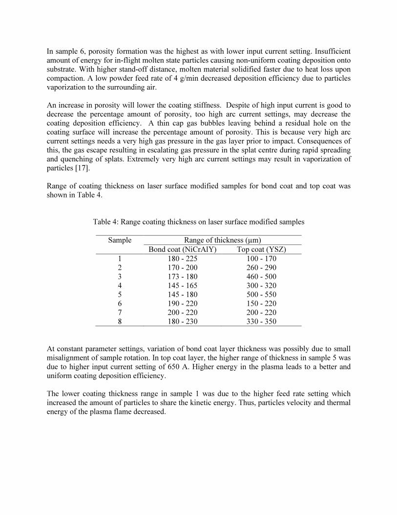
distribution is given in Figure 2(b). Porosity content in both coating layers of each sample is
shown by Figure 3. Porosity percentage in top coat varied with parameter settings. The lowest
porosity percentage of 41% in top coat was measured from sample 5 which was deposited at
higher input current, 650 A, higher feed rate, 51.7 g/min and lower stand-off distance, 100 mm.
The highest porosity of 63% was analyzed in sample 6 which was coated at lower input current,
550 A, lower feed rate, 36.3 g/min and higher stand-off distance, 120 mm. In bond coat layer, the
porosity content was in the range of 3 to 18%.
[A]
[B]
[C]
[D]
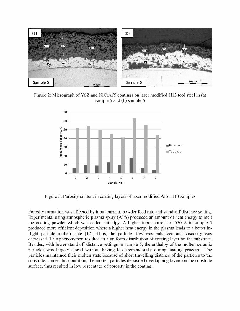
Figure 2: Micrograph of YSZ and NiCrAlY coatings on laser modified H13 tool steel in (a)
sample 5 and (b) sample 6
Figure 3: Porosity content in coating layers of laser modified AISI H13 samples
Porosity formation was affected by input current, powder feed rate and stand-off distance setting.
Experimental using atmospheric plasma spray (APS) produced an amount of heat energy to melt
the coating powder which was called enthalpy. A higher input current of 650 A in sample 5
produced more efficient deposition where a higher heat energy in the plasma leads to a better in-
flight particle molten state [12]. Thus, the particle flow was enhanced and viscosity was
decreased. This phenomenon resulted in a uniform distribution of coating layer on the substrate.
Besides, with lower stand-off distance settings in sample 5, the enthalpy of the molten ceramic
particles was largely stored without having lost tremendously during coating process. The
particles maintained their molten state because of short travelling distance of the particles to the
substrate. Under this condition, the molten particles deposited overlapping layers on the substrate
surface, thus resulted in low percentage of porosity in the coating.
(a)
Sample 5
(b)
Sample 6
In sample 6, porosity formation was the highest as with lower input current setting. Insufficient
amount of energy for in-flight molten state particles causing non-uniform coating deposition onto
substrate. With higher stand-off distance, molten material solidified faster due to heat loss upon
compaction. A low powder feed rate of 4 g/min decreased deposition efficiency due to particles
vaporization to the surrounding air.
An increase in porosity will lower the coating stiffness. Despite of high input current is good to
decrease the percentage amount of porosity, too high arc current settings, may decrease the
coating deposition efficiency. A thin cap gas bubbles leaving behind a residual hole on the
coating surface will increase the percentage amount of porosity. This is because very high arc
current settings needs a very high gas pressure in the gas layer prior to impact. Consequences of
this, the gas escape resulting in escalating gas pressure in the splat centre during rapid spreading
and quenching of splats. Extremely very high arc current settings may result in vaporization of
particles [17].
Range of coating thickness on laser surface modified samples for bond coat and top coat was
shown in Table 4.
Table 4: Range coating thickness on laser surface modified samples
Sample Range of thickness (µm)
Bond coat (NiCrAlY) Top coat (YSZ)
1 180 - 225 100 - 170
2 170 - 200 260 - 290
3 173 - 180 460 - 500
4 145 - 165 300 - 320
5 145 - 180 500 - 550
6 190 - 220 150 - 220
7 200 - 220 200 - 220
8 180 - 230 330 - 350
At constant parameter settings, variation of bond coat layer thickness was possibly due to small
misalignment of sample rotation. In top coat layer, the higher range of thickness in sample 5 was
due to higher input current setting of 650 A. Higher energy in the plasma leads to a better and
uniform coating deposition efficiency.
The lower coating thickness range in sample 1 was due to the higher feed rate setting which
increased the amount of particles to share the kinetic energy. Thus, particles velocity and thermal
energy of the plasma flame decreased.
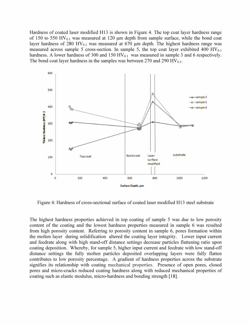
Hardness of coated laser modified H13 is shown in Figure 4. The top coat layer hardness range
of 150 to 550 HV0.1 was measured at 120 μm depth from sample surface, while the bond coat
layer hardness of 280 HV0.1 was measured at 670 μm depth. The highest hardness range was
measured across sample 5 cross-section. In sample 5, the top coat layer exhibited 400 HV0.1
hardness. A lower hardness of 300 and 150 HV0.1 was measured in sample 3 and 6 respectively.
The bond coat layer hardness in the samples was between 270 and 290 HV0.1.
Figure 4: Hardness of cross-sectional surface of coated laser modified H13 steel substrate
The highest hardness properties achieved in top coating of sample 5 was due to low porosity
content of the coating and the lowest hardness properties measured in sample 6 was resulted
from high porosity content. Referring to porosity content in sample 6, pores formation within
the molten layer during solidification altered the coating layer integrity. Lower input current
and feedrate along with high stand-off distance settings decrease particles flattening ratio upon
coating deposition. Whereby, for sample 5, higher input current and feedrate with low stand-off
distance settings the fully molten particles deposited overlapping layers were fully flatten
contributes to low porosity percentage. A gradient of hardness properties across the substrate
signifies its relationship with coating mechanical properties. Presence of open pores, closed
pores and micro-cracks reduced coating hardness along with reduced mechanical properties of
coating such as elastic modulus, micro-hardness and bonding strength [18].
Conclusion
Higher settings of input current, 650 A and feed rate, 51.7 g/min along with lower setting of
stand-off distance, 100 mm have significant effect on the microscopy findings of coating
thickness, coating porosity and hardness. Higher input current setting assist in increasing the
thermal energy during APS coating. While, feed rate supply the sufficient amount of powder for
efficient coating deposition. Low stand-off distance maintain the particles enthalpy by reducing
molten particles heat loss to surrounding air.
Acknowledgement
This work was supported by Universiti Malaysia Pahang and Fundamental Research Grant
Scheme-RDU120105 from Ministry of Higher Education Malaysia.
References
[1] Amit Srivastava, Vivek Joshi, Rajiv Shivpuri, Rabi Bhattacharya, Satish Dixit, A multilayer
coating architecture to reduce heat checking of die surfaces, Surface and Coatings Technology,
Volumes 163–164, 30 January 2003, Pages 631-636, ISSN 0257-8972, 10.1016/S0257-
8972(02)00690-4.
[2] L.J.D. Sully, in "Metals Handbook, 9th ed., vol. 15" (ASMInternational, Metals Park,
Ohio, 1988) p. 286.
[3] J.R. Davis (Ed.), in "ASMSpeciality Handbook, Tool Materials" (ASMInternational,
Materials Park, Ohio, 1995) p. 251.
[4] D.F. ALLSOP, D. KENNEDY, in "Pressure diecasting, Part 2: The technology of the casting
and the die" (Pergamon Press Ltd, Oxford, 1983).
[5] JR Davis, Introduction to Thermal Spray Processing, Handbook of Thermal Spray
Technologies, ed., ASM International, Materials Park, OH, p. 3–9, 2004.
[6] R.C. Tucker, Jr., Thermal Spray Coatings, Surface Engineering,
Vol 5, ASM Handbook, ASM International, 1994, p 497–509.
[7] A. Abdellah El-Hadj, M. Zirari, N. Bacha, Numerical analysis of the effect of the gas
temperature on splat formation during thermal spray process, Applied Surface Science, Volume
257, Issue 5, 15 December 2010, Pages 1643-1648, ISSN 0169-4332.
[8] C.J. Li, A. O hmori, J. Therm. Spray Technol., 11 (2002), p. 365
[9] L. Wang, J.C. Fang, Z.Y. Zhao, H.P. Zeng, Application of backward propagation network for
forecasting hardness and porosity of coatings by plasma spraying, Surface and Coatings
Technology, 201 (2007), pp. 5085–5089
[10] X.C. Zhang, B.S. Xu, F.Z. Xuan, H.D. Wang, Y.X. Wu, S.T. Tu, Statistical analyses of
porosity variations in plasma-sprayed Ni-based coatings, Journal of Alloys and Compounds, 467
(2009), pp. 501–508
[11] S. Deshpande, A. Kulkarni, S. Sampath, H. Herman, Application of image analysis for
characterization of porosity in thermal spray coatings and correlation with small angle neutron
scattering, Surface and Coatings Technology, 187 (2004), pp. 6–16
[12] R. Venkataraman, G. Dasa, S.R. Singh, L.C. Pathak, R.N. Ghosha, B. Venkataraman, R.
Krishnamurthy, Study on influence of porosity, pore size, spatial and topological distribution of
pores on micro-hardness of as plasma sprayed ceramic coatings, Materials Science and
Engineering, 445 (2007), pp. 269–274
[13] S. Guessasma, C. Coddet, Neural computation applied to APS spray process: porosity
analysis, Surface and Coatings Technology, 197 (2005), pp. 85–92
[14] de Lovelock HL, Villers RPW, Benson JM, Young PM (1998) Parameter study of
HP/HVOF deposited WC-Co coatings. J Thermal Spray Technol 7(1):97–107.
[15] Kingswell R, Scott KT, Wassell LL (1993) Optimizing the vacuum plasma spray deposition
of metal, ceramic, and cermet coatings using designed experiments. J Thermal Spray Technol
2(2):179–186.
[16] Burlacov I, Jirkovsky J, Muller M, Heimann RB (2006) Induction plasma-sprayed
photocatalytically active titania coatings and their characterization by micro-Raman
spectroscopy. Surf Coat Technol 201:255–264.
[17] R. Venkataraman, G. Dasa, S.R. Singh, L.C. Pathak, R.N. Ghosha, B. Venkataraman, R.
Krishnamurthy, Study on influence of porosity, pore size, spatial and topological distribution of
pores on micro-hardness of as plasma sprayed ceramic coatings, Materials Science and
Engineering, 445 (2007), pp. 269–274
[18] I.Yu. Konyashin, T.V. Chukalovskaya, A technique for measurement of porosity in
protective coatings, Surface and Coatings Technology, 88 (1996), pp. 5–11
[19] Hao Du, Soo Wohn Lee, Jae Heyg Shin, Study on porosity of plasma-sprayed coatings by
digital image analysis method, Journal of Thermal Spray Technology, 14 (2005), pp. 453–461