thermal integrity profiling (tip) drilled shafts in … · · 2015-11-06thermal integrity...
TRANSCRIPT

THERMAL INTEGRITY PROFILING (TIP)Drilled Shafts in South Carolina

THERMAL INTEGRITY PROFILING (TIP)Drilled Shafts in South Carolina
Non-Destructive Test (NDT) MethodsCrosshole Sonic Logging (CSL) and TIP
Carolina Bays Parkway Phase III TIP; Probe, Embedded Wires, Suspended Wires
US-15 O-Cell Test ShaftManufactured Anomalies
Project YEEO (for Your Eyes and Ears Only)Aggressive Schedule
David Schoen, EITS&ME, Inc. [email protected], SC 843-884-0005
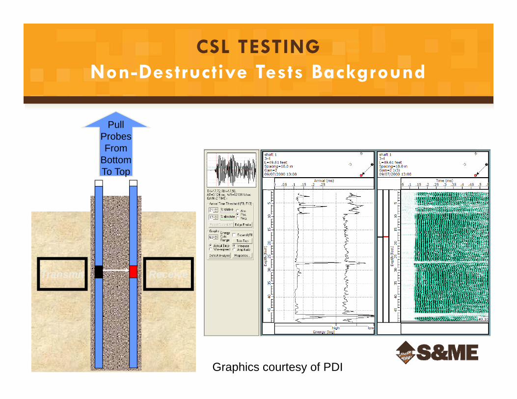
ReceiveTransmit
PullProbesFrom
BottomTo Top
Graphics courtesy of PDI
CSL TESTINGNon-Destructive Tests Background
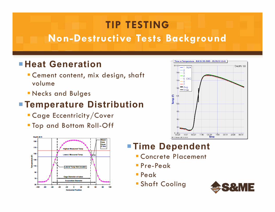
TIP TESTINGNon-Destructive Tests Background
Heat Generation Cement content, mix design, shaft
volumeNecks and Bulges
Temperature Distribution Cage Eccentricity/Cover Top and Bottom Roll-Off
Time Dependent Concrete Placement Pre-Peak Peak Shaft Cooling
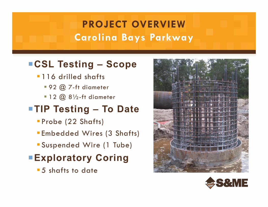
PROJECT OVERVIEWCarolina Bays Parkway
CSL Testing – Scope116 drilled shafts 92 @ 7-ft diameter 12 @ 8½-ft diameter
TIP Testing – To DateProbe (22 Shafts) Embedded Wires (3 Shafts)Suspended Wire (1 Tube)
Exploratory Coring5 shafts to date
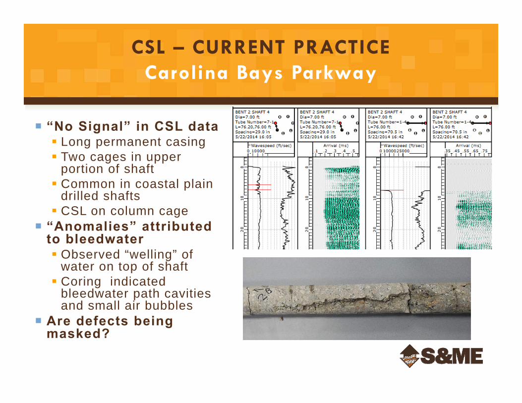
“No Signal” in CSL data Long permanent casing Two cages in upper
portion of shaft Common in coastal plain
drilled shafts CSL on column cage
“Anomalies” attributed to bleedwater Observed “welling” of
water on top of shaft Coring indicated
bleedwater path cavities and small air bubbles
Are defects being masked?
CSL – CURRENT PRACTICECarolina Bays Parkway
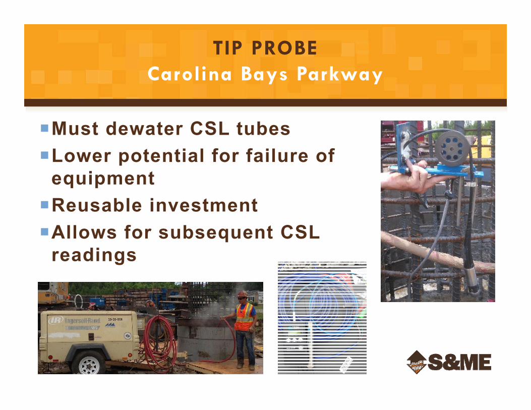
TIP PROBECarolina Bays Parkway
Must dewater CSL tubesLower potential for failure of
equipmentReusable investmentAllows for subsequent CSL
readings
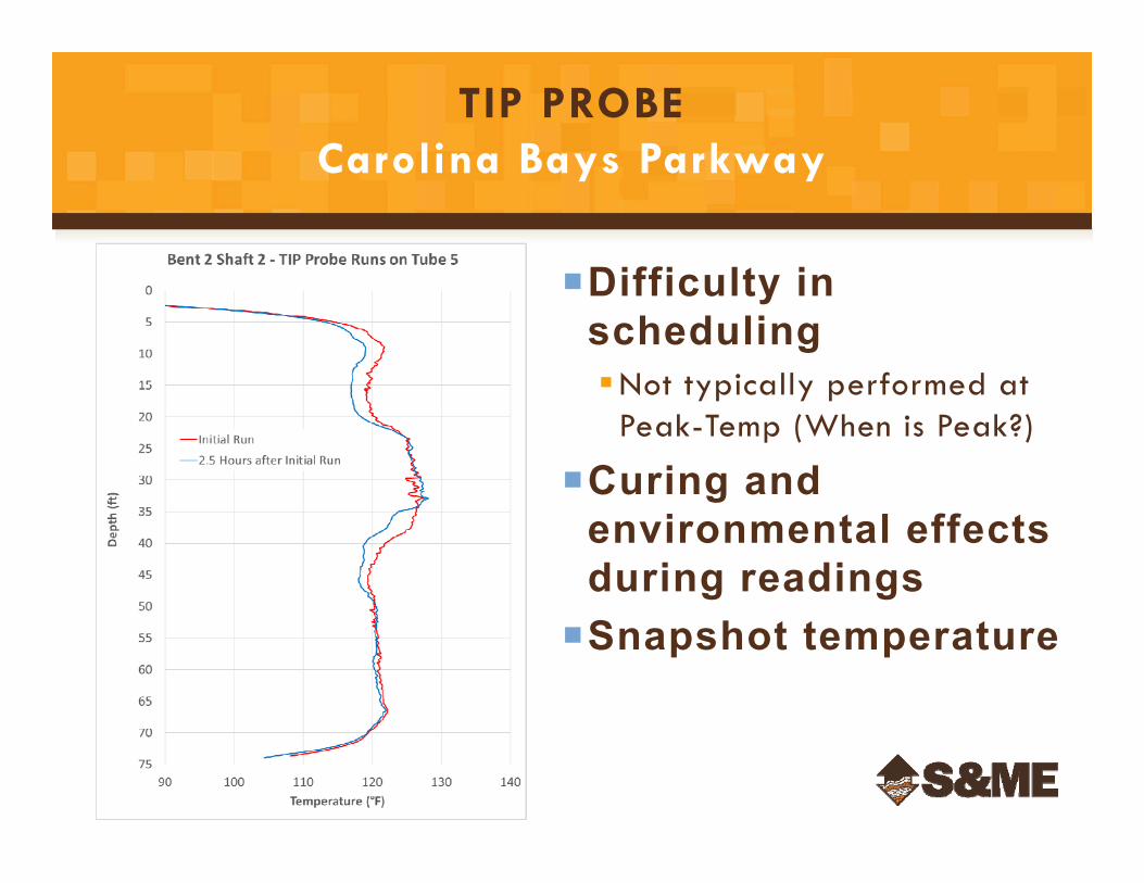
TIP PROBECarolina Bays Parkway
Difficulty in schedulingNot typically performed at
Peak-Temp (When is Peak?)
Curing and environmental effects during readingsSnapshot temperature
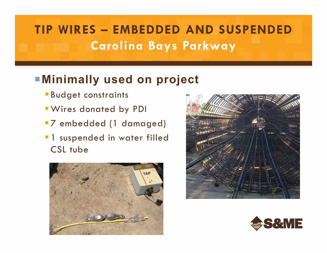
Minimally used on projectBudget constraintsWires donated by PDI7 embedded (1 damaged)1 suspended in water filled
CSL tube
TIP WIRES – EMBEDDED AND SUSPENDEDCarolina Bays Parkway
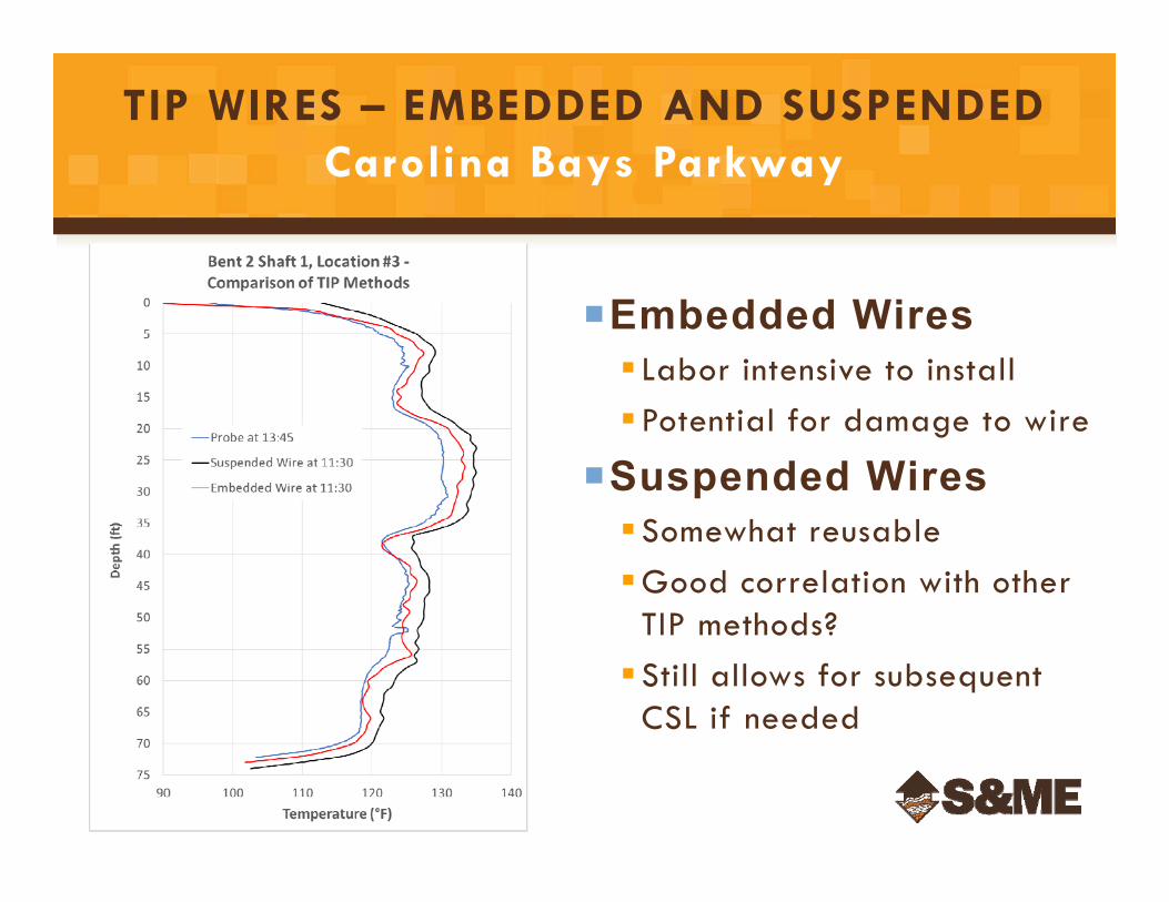
TIP WIRES – EMBEDDED AND SUSPENDEDCarolina Bays Parkway
Embedded Wires Labor intensive to installPotential for damage to wire
Suspended WiresSomewhat reusableGood correlation with other
TIP methods?Still allows for subsequent
CSL if needed
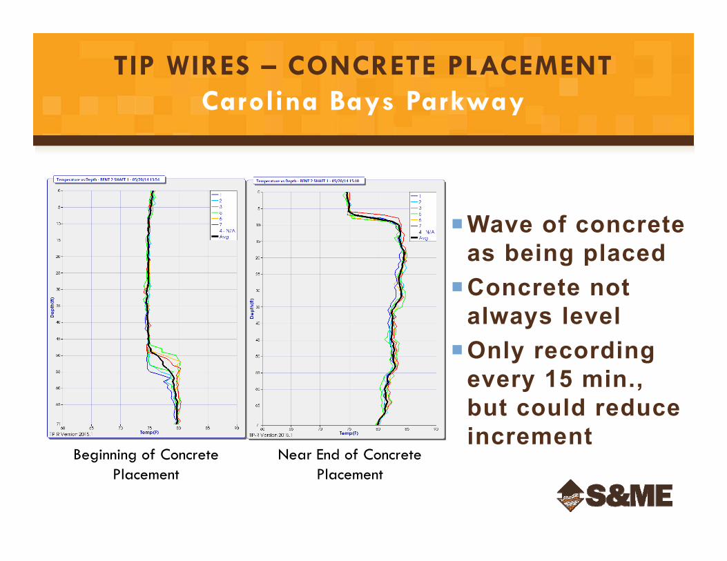
Wave of concrete as being placed
Concrete not always level
Only recording every 15 min., but could reduce increment
TIP WIRES – CONCRETE PLACEMENTCarolina Bays Parkway
Beginning of Concrete Placement
Near End of Concrete Placement
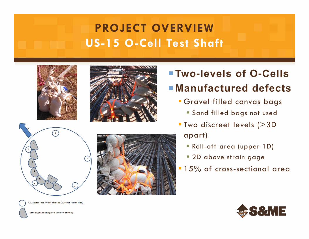
Two-levels of O-CellsManufactured defectsGravel filled canvas bags Sand filled bags not used
Two discreet levels (>3D apart) Roll-off area (upper 1D) 2D above strain gage
15% of cross-sectional area
PROJECT OVERVIEWUS-15 O-Cell Test Shaft
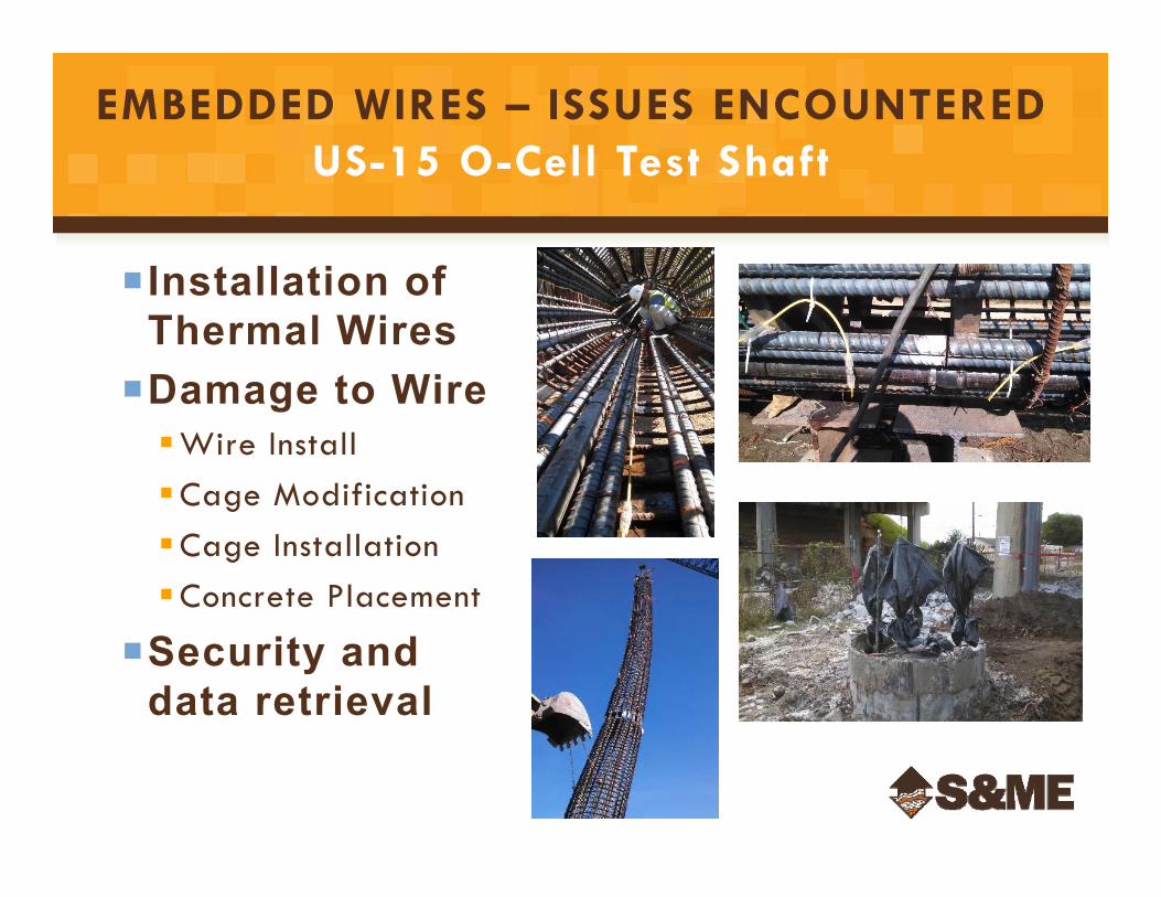
Installation of Thermal WiresDamage to WireWire InstallCage ModificationCage InstallationConcrete Placement
Security and data retrieval
EMBEDDED WIRES – ISSUES ENCOUNTEREDUS-15 O-Cell Test Shaft
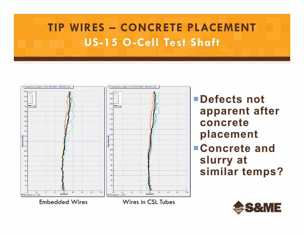
Defects not apparent after concrete placementConcrete and
slurry at similar temps?
TIP WIRES – CONCRETE PLACEMENTUS-15 O-Cell Test Shaft
Embedded Wires Wires in CSL Tubes
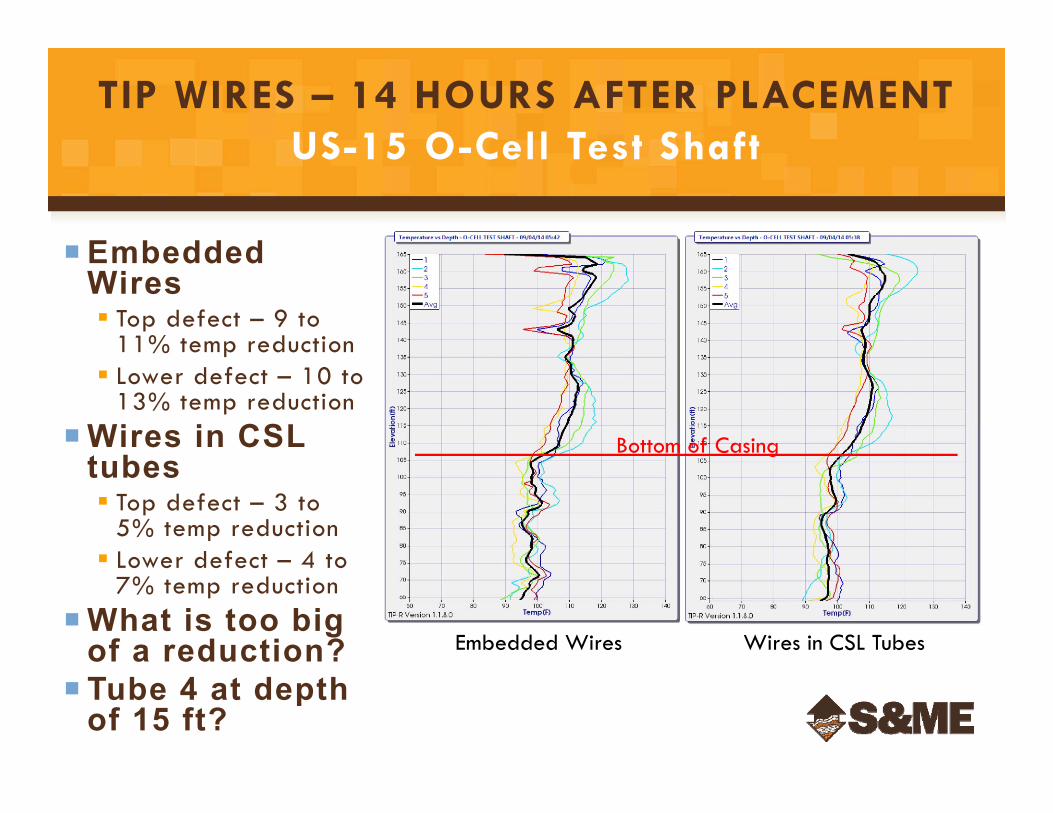
Embedded Wires Top defect – 9 to
11% temp reduction Lower defect – 10 to
13% temp reductionWires in CSL
tubes Top defect – 3 to
5% temp reduction Lower defect – 4 to
7% temp reductionWhat is too big
of a reduction? Tube 4 at depth
of 15 ft?
TIP WIRES – 14 HOURS AFTER PLACEMENTUS-15 O-Cell Test Shaft
Embedded Wires Wires in CSL Tubes
Bottom of Casing
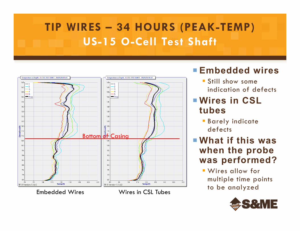
Embedded wires Still show some
indication of defects
Wires in CSL tubes Barely indicate
defects
What if this was when the probe was performed?Wires allow for
multiple time points to be analyzed
TIP WIRES – 34 HOURS (PEAK-TEMP)US-15 O-Cell Test Shaft
Embedded Wires Wires in CSL Tubes
Bottom of Casing
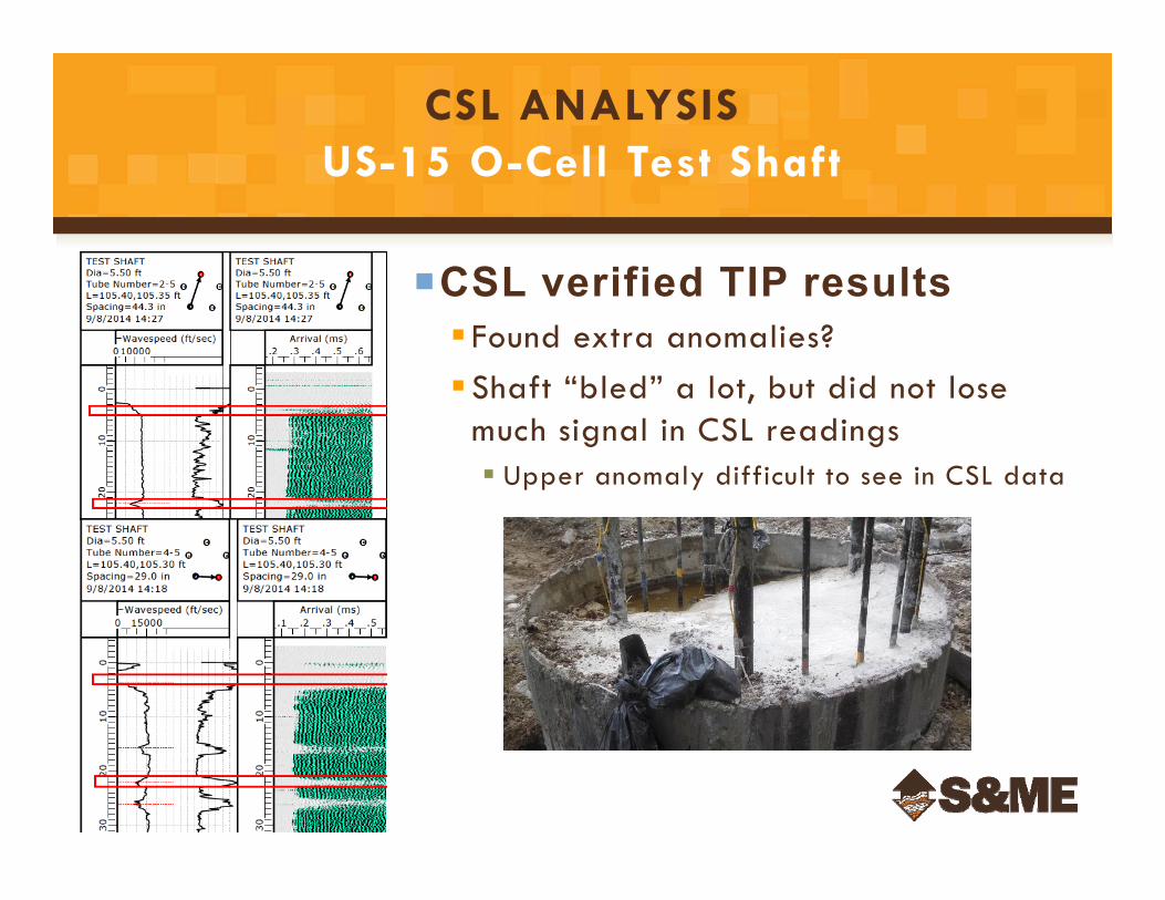
CSL verified TIP results Found extra anomalies?Shaft “bled” a lot, but did not lose
much signal in CSL readings Upper anomaly difficult to see in CSL data
CSL ANALYSISUS-15 O-Cell Test Shaft
SUSPENDED TIP WIRES – GRADIENT Back to Carolina Bays Parkway
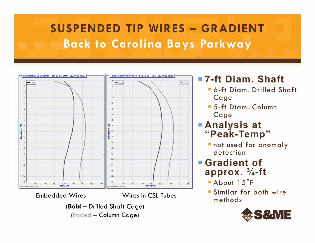
Wires in CSL TubesEmbedded Wires
7-ft Diam. Shaft 6-ft Diam. Drilled Shaft
Cage 5-ft Diam. Column
CageAnalysis at
“Peak-Temp” not used for anomaly
detectionGradient of
approx. ¾-ft About 15°F Similar for both wire
methods(Bold – Drilled Shaft Cage)
(Faded – Column Cage)
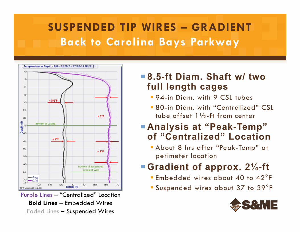
SUSPENDED TIP WIRES – GRADIENT Back to Carolina Bays Parkway
8.5-ft Diam. Shaft w/ two full length cages 94-in Diam. with 9 CSL tubes 80-in Diam. with “Centralized” CSL
tube offset 1½-ft from center
Analysis at “Peak-Temp” of “Centralized” Location About 8 hrs after “Peak-Temp” at
perimeter location
Gradient of approx. 2¼-ft Embedded wires about 40 to 42°F Suspended wires about 37 to 39°F
Purple Lines – “Centralized” LocationBold Lines – Embedded Wires
Faded Lines – Suspended Wires
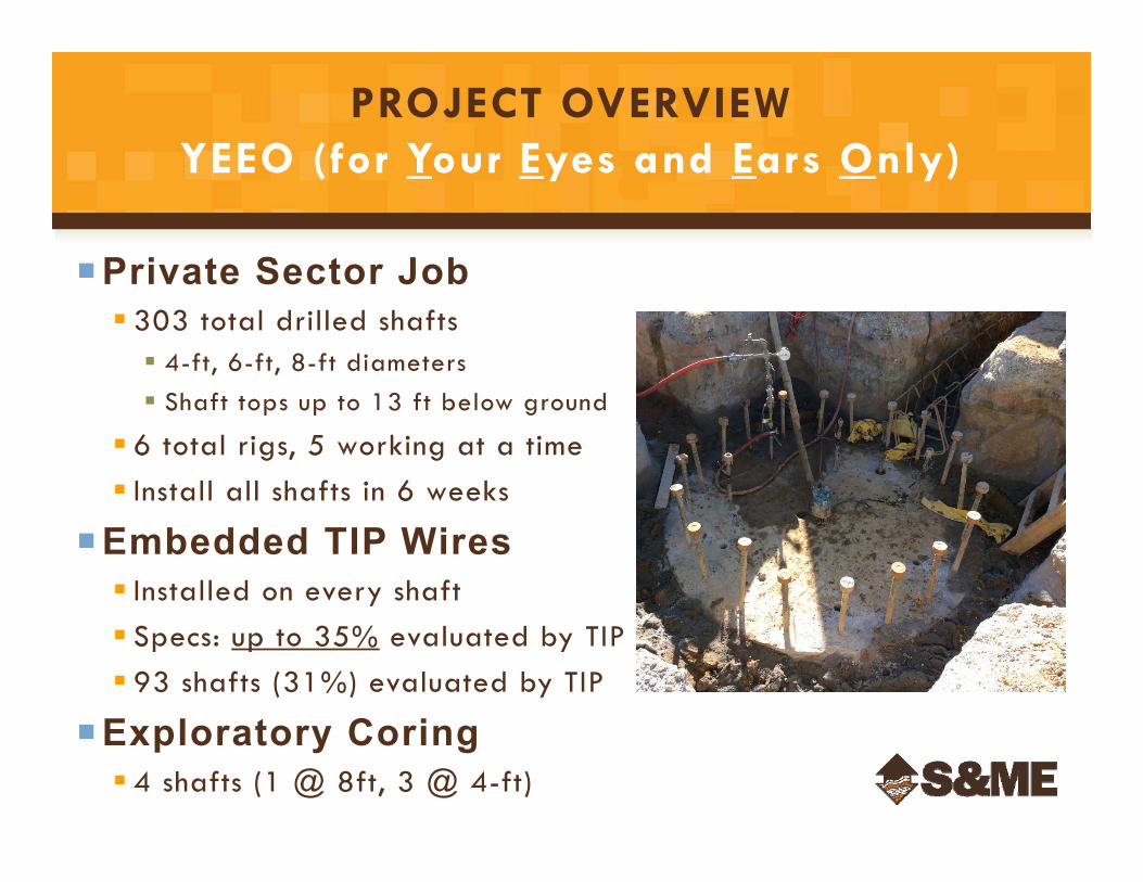
PROJECT OVERVIEWYEEO (for Your Eyes and Ears Only)
Private Sector Job 303 total drilled shafts 4-ft, 6-ft, 8-ft diameters Shaft tops up to 13 ft below ground
6 total rigs, 5 working at a time Install all shafts in 6 weeks
Embedded TIP Wires Installed on every shaft Specs: up to 35% evaluated by TIP 93 shafts (31%) evaluated by TIP
Exploratory Coring 4 shafts (1 @ 8ft, 3 @ 4-ft)
1,680 Total TIP Wires Installed (≈70,000 LF)At top of cage, wires tied to single sister barCages moved multiple timesConcrete placed by freefallUncased excavation backfilled93 shafts (516 wires) evaluated by TIP 45 wires (8.7%) did not work at all 67 wires (13.0%) did not work entire time/depth
86 shafts (464 wires) checked to determine if wires working 156 wires (33.8%) giving error light
DAMAGE TO TIP WIRESYEEO
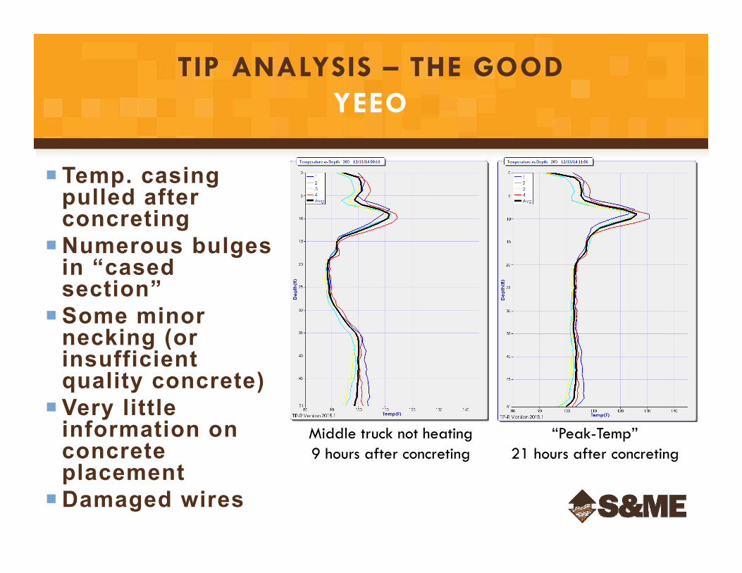
TIP ANALYSIS – THE GOODYEEO
Temp. casing pulled after concreting
Numerous bulges in “cased section”
Some minor necking (or insufficient quality concrete)
Very little information on concrete placement
Damaged wires
Middle truck not heating9 hours after concreting
“Peak-Temp”21 hours after concreting
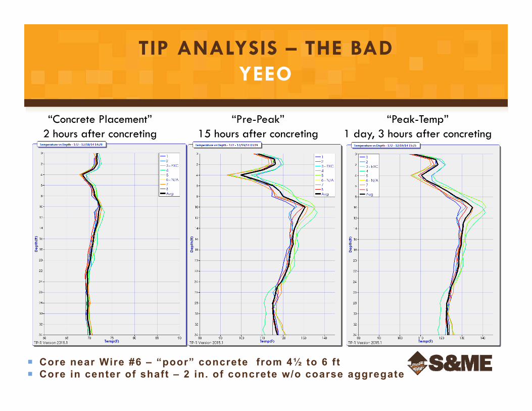
TIP ANALYSIS – THE BADYEEO
“Concrete Placement”2 hours after concreting
“Pre-Peak”15 hours after concreting
“Peak-Temp”1 day, 3 hours after concreting
Core near Wire #6 – “poor” concrete from 4½ to 6 ft Core in center of shaft – 2 in. of concrete w/o coarse aggregate
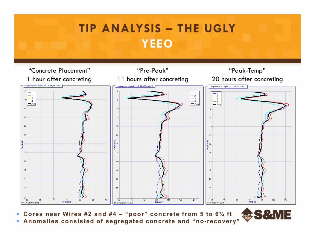
TIP ANALYSIS – THE UGLYYEEO
“Concrete Placement”1 hour after concreting
“Pre-Peak”11 hours after concreting
“Peak-Temp”20 hours after concreting
Cores near Wires #2 and #4 – “poor” concrete from 5 to 6¼ ft Anomalies consisted of segregated concrete and “no-recovery”
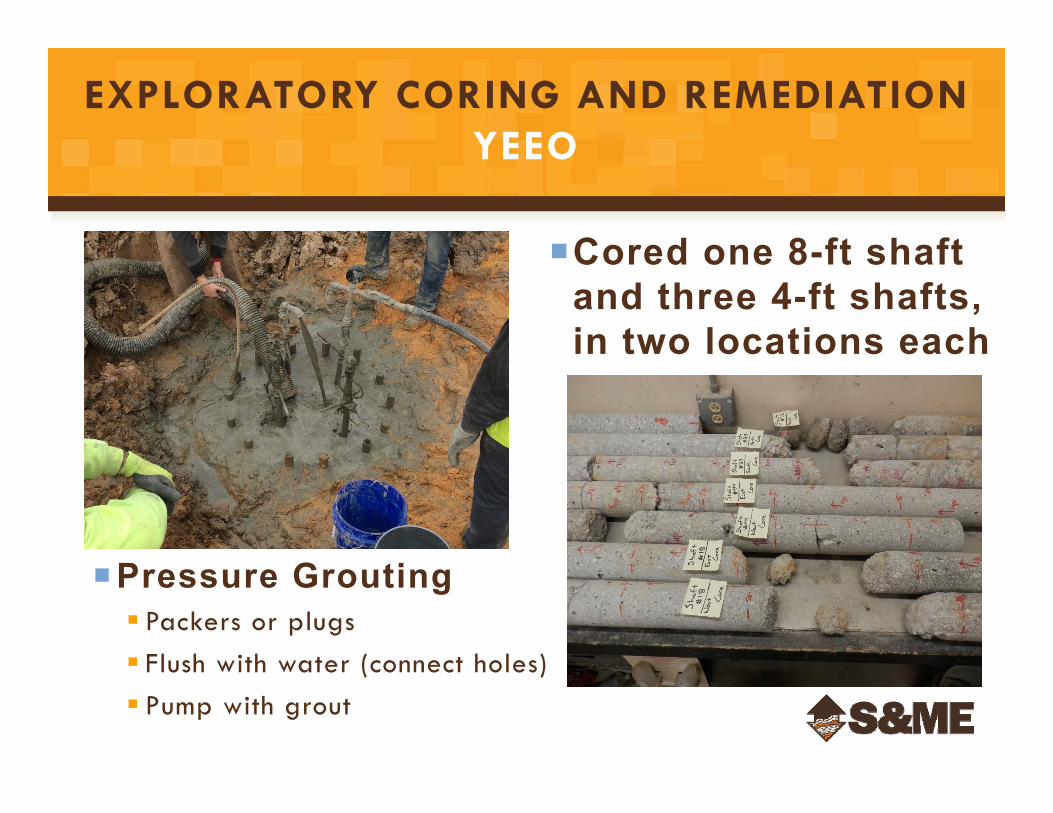
EXPLORATORY CORING AND REMEDIATIONYEEO
Cored one 8-ft shaft and three 4-ft shafts, in two locations each
Pressure Grouting Packers or plugs Flush with water (connect holes) Pump with grout
ANY QUESTIONS?Did I Leave Enough Time?
Where can I get some dam beer?