thermal mass flowmeter t-mass s
TRANSCRIPT

Technical InformationTI 0013A/05/e/07.99 Thermal mass Flowmeter
t-mass S
Direct Mass Flow Measurement of Gases
Hauser+EndressThe Power of Know How
Features• SMART technology permits two-way di-
gital communication via HARTprotocol
• One standard, compact meter for all ga-ses with a process temperature rangeof -10...+100°C
• Negligible pressure losses• Single point measurement• Wide turndown of up to 100:1• Every sensor is delivered with a
calibration certificate traceable toNational Standards
Flexibility and Convenience• t-mass measures the mass flow in the
process. It can be programmed todisplay the flow rate in a wide range ofengineering units includingstandardised volume.
• Local, manual configuration is possiblewith the housing closed, even inhazardous areas
• Current and pulse simulation mode forcommissioning and diagnosis
• Insertion (AT70), flanged (AT70F) andwafer (AT70W) flowcell formatsprovide compatibility with any pipelineor ducting installations.
• Can be supplied to suit a wide range ofprocess pipe sizes and connections tosuit all areas of industry
• Display and the complete electronichousing can be rotated to enable thebest viewing angles
Safety• CE mark compliance with
electromagnetic compatibilityaccording to EN50081-1:1992and EN50082-1:1992
• Approved for hazardous areaoperation
• All meters hydrostaticallypressure-tested
• Sensor electronics featureself-diagnostics with alarm functions
Applications
t-massMeasuring System
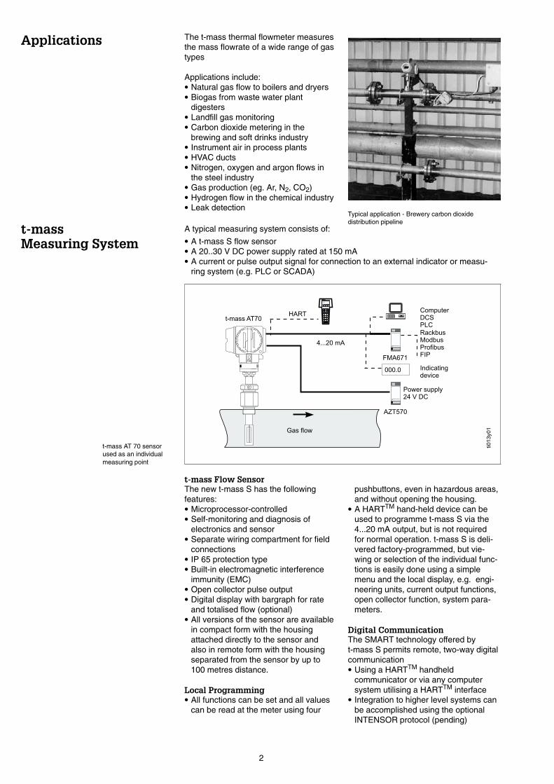
The t-mass thermal flowmeter measuresthe mass flowrate of a wide range of gastypes
Applications include:• Natural gas flow to boilers and dryers• Biogas from waste water plant
digesters• Landfill gas monitoring• Carbon dioxide metering in the
brewing and soft drinks industry• Instrument air in process plants• HVAC ducts• Nitrogen, oxygen and argon flows in
the steel industry• Gas production (eg. Ar, N2, CO2)• Hydrogen flow in the chemical industry• Leak detection
t-mass Flow SensorThe new t-mass S has the followingfeatures:• Microprocessor-controlled• Self-monitoring and diagnosis of
electronics and sensor• Separate wiring compartment for field
connections• IP 65 protection type• Built-in electromagnetic interference
immunity (EMC)• Open collector pulse output• Digital display with bargraph for rate
and totalised flow (optional)• All versions of the sensor are available
in compact form with the housingattached directly to the sensor andalso in remote form with the housingseparated from the sensor by up to100 metres distance.
Local Programming• All functions can be set and all values
can be read at the meter using four
pushbuttons, even in hazardous areas,and without opening the housing.
• A HARTTM hand-held device can beused to programme t-mass S via the4...20 mA output, but is not requiredfor normal operation. t-mass S is deli-vered factory-programmed, but vie-wing or selection of the individual func-tions is easily done using a simplemenu and the local display, e.g. engi-neering units, current output functions,open collector function, system para-meters.
Digital CommunicationThe SMART technology offered byt-mass S permits remote, two-way digitalcommunication• Using a HARTTM handheld
communicator or via any computersystem utilising a HARTTM interface
• Integration to higher level systems canbe accomplished using the optionalINTENSOR protocol (pending)
t-mass AT 70 sensorused as an individualmeasuring point
A typical measuring system consists of:• A t-mass S flow sensor• A 20..30 V DC power supply rated at 150 mA• A current or pulse output signal for connection to an external indicator or measu-
ring system (e.g. PLC or SCADA)
ti013
y01
Typical application - Brewery carbon dioxidedistribution pipeline
2
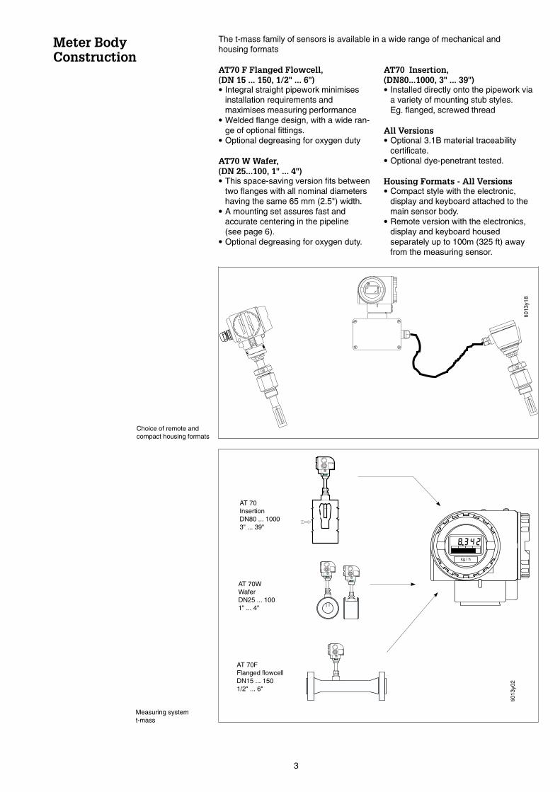
Meter BodyConstruction
AT70 F Flanged Flowcell,(DN 15 ... 150, 1/2" ... 6")• Integral straight pipework minimises
installation requirements andmaximises measuring performance
• Welded flange design, with a wide ran-ge of optional fittings.
• Optional degreasing for oxygen duty
AT70 W Wafer,(DN 25...100, 1" ... 4")• This space-saving version fits between
two flanges with all nominal diametershaving the same 65 mm (2.5") width.
• A mounting set assures fast andaccurate centering in the pipeline(see page 6).
• Optional degreasing for oxygen duty.
AT70 Insertion,(DN80...1000, 3" ... 39")• Installed directly onto the pipework via
a variety of mounting stub styles.Eg. flanged, screwed thread
All Versions• Optional 3.1B material traceability
certificate.• Optional dye-penetrant tested.
Housing Formats - All Versions• Compact style with the electronic,
display and keyboard attached to themain sensor body.
• Remote version with the electronics,display and keyboard housedseparately up to 100m (325 ft) awayfrom the measuring sensor.
Measuring systemt-mass
Choice of remote andcompact housing formats
AT 70InsertionDN80 ... 10003" ... 39"
AT 70WWaferDN25 ... 1001" ... 4"
AT 70FFlanged flowcellDN15 ... 1501/2" ... 6"
ti013
y02
ti013
y18
The t-mass family of sensors is available in a wide range of mechanical andhousing formats
3

Function
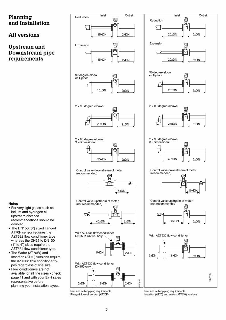
Planningand Installation
Piping requirements
Measuring PrincipleThermal metering is now a wellestablished method of mass flowmeasurement. It operates by monitoringthe cooling effect of a gas stream as itpasses over a heated transducer.Gas flowing through the sensing sectionpasses over two PT100 RTDtransducers. One PT100 is usedconventionally as a temperature sensingdevice, whilst the other is used as a hea-ter. The temperature transducer moni-tors the actual gas processtemperature, whilst the self-heatedtransducer is maintained at a constantdifferential temperature (relative to themeasured gas temperature) by varyingthe current through it. The greater themass flow passing over the heatedtransducer, the greater the coolingeffect, and current required to keep aconstant differential temperature. Themeasured heater current is therefore ameasure of the gas mass flowrate.
The Measuring SensorEach AT 70 flow sensor has a four wireconnection. Two wires carry the powersupply and two wires transmit themeasured flow signal back to the controlroom either as a 4-20 mA current outputor as an open collector transistor pulseoutput. In addition the current outputconnection supports the HARTTM
communication facility allowing remoteinterrogation of the flow, totalised flowand process gas temperature values aswell as configuration of the sensor.
CalibrationEach sensor is subjected to thorough ca-libration and test procedures and is supp-lied with an individual calibration certifica-te traceable to NationalStandards
Thermal measuring principle
View through the sensor pipe - t-mass AT 70W
ti013
y19
The following installation recommendations should be observed as the minimumrequirements when installing t-mass in the pipeline.
Inlet and Outlet SectionsThe high sensitivity of the thermal dispersion principle to low flow rates means the flo-wmeter can also be sensitive to internal disturbances in flowing gas steam (eg. swirl)especially in the smaller pipe diameters (=<DN150, 6"). The installed thermal flowsensor should therefore be installed as far as possible upstream of any flowdisturbances. Disturbance sources can be split into two broad categories:
Construction and/or Assembly Quality.Good construction practice should be followed at all times:
• Cleaned pipe and flange welded joints• Correctly sized gaskets• Correctly aligned flanges and gaskets• The use of seamless pipe immediately upstream of the flowmeter• The use of pipework with a matching internal diameter to that of the flowmeter to
ensure that no step disturbance greater than 1 mm (0.05") can occur at the meterinlet or outlet. (3 mm [0.125"] for diameters > DN200 [8"])
• As a general comment anything that disturbs the smoothness of the internalpipe wall within the dimensions stated on page 6 should be eliminated - the goalshould be a smooth uninterrupted internal surface.
4

Process Components or Pipework ConfigurationWhen disturbances (eg. pipe elbows, reducers, valves, T-pieces etc.) arelocated upstream of the thermal meter, precautions must be taken to minimise anyeffects on the measuring performance.The figures on page 6 illustrate the minimum recommended upstream clear pipelengths expressed in multiples of the pipe diameter (x DN), longer lengths shouldalways be used if they are available in the metering run.Regardless of any other consideration the minimum recommendations for clearpipework on either side of the sensor are:
• Inlet sections:minimum 15 x DN for the flanged flowcell (AT70F) version.minimum 20 x DN for the insertion (AT70) or wafer flowcell (AT70W) version.
• Outlet sections:minimum 2 x DN for the flanged flowcell (AT70F) version.minimum 5 x DN for the insertion (AT70) or wafer flowcell (AT70W) version.
Notes:• Where two or more disturbances are located upstream of the meter, the longest
recommended upstream pipe section is to be observed as an absoluteminimum.
• It is always recommended to install control valves downstream of the flowmeter.• When an upstream disturbance is present whose disturbing effect cannot be rea-
dily evaluated (e.g a dryer, other measuring device such as an orifice plate, turbinemeter, vortex meter), it is recommended to consider the disturbance in the sameway as a valve (see page 6).
• For very light gases such as helium and hydrogen all recommendedupstream straight section values should be multiplied by two.
• Free-standing pipes subject to strong vibration should be firmly attached orsupported upstream and downstream of the meter.
Flow ConditionerWith limited space and large pipes, it is not always possible to have the inlet sectionsgiven above. The specially developed AZT532 and AZT534 perforated plate flowconditioners in all but the most severe cases of pipeline disturbances allows thesensor to be installed in the pipework with reduced upstream clear distances. Referto page 11 for further guidelines.
Pressure Pulses/measuring AccuracyReciprocating pumps and some compressor systems can create strong changes inprocess pressure in the piping that can induce spurious internal flow patterns andthus cause additional measuring errors. These pressure pulses must be reduced bythe appropriate measures. Eg.• Using expansion tanks• With inlet expanders• With a more suitable mounting location
Pipework construction and assembly considerations - conditions to avoid
5
Planningand Installation
All versions
Upstream andDownstream piperequirements
ti031
y03
Inlet and outlet piping requirementsInsertion (AT70) and Wafer (AT70W) versions
Inlet and outlet piping requirementsFlanged flowcell version (AT70F)
ti013
y06
Notes• For very light gases such as
helium and hydrogen allupstream distancerecommendations should bedoubled.
• The DN150 (6") sized flangedAT70F sensor requires theAZT532 flow conditioner typewhereas the DN25 to DN100(1" to 4") sizes require theAZT534 flow conditioner type.
• The Wafer (AT70W) andInsertion (AT70) versions requirethe AZT532 flow conditioner ty-pes regardless of line size.
• Flow conditioners are notavailable for all line sizes - checkpage 11 and with your E+H salesrepresentative beforeplanning your installation layout.
6

Mounting set for wafer version (AT 70W)
Note the following points before mounting the AT70W sensor:• The flowcell and wafer style meter bodies are protected against damage during
transit by two protective disks. Remove both protective disks before installing theflowmeter in the pipeline.
• Take particular care that the internal diameters of any installed gaskets directlyupstream and downstream of the meter body are identical or larger than those ofthe meter body and/or process piping. Gaskets which protude into the flow willinvariably lead to metering inaccuracies.
Mounting SetTo ensure the accurate centering of wafer style meters with respect to the flangefitting on any pipework installation, it is essential for maximum performance that themounting set supplied with the sensor is used.Each mounting kit comprises• A set of correctly sized fixing bolts• Accurately dimensioned centering rings
Mounting Procedure• Place one centering ring over each side of the meter body• Mount two or more bolts as required with washers on both piping flanges• Adjust the sensor together with the two centering rings between the bolts already
mounted and the piping flanges (including gaskets)• Mount the rest of the bolts• Screw tight the bolts in a diagonal tightening pattern
Planningand Installation
AT70WWafer version only
7
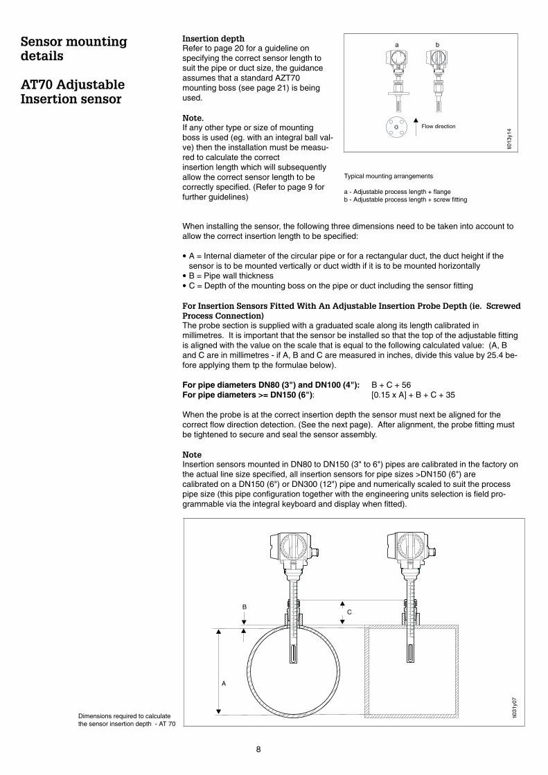
Sensor mountingdetails
AT70 AdjustableInsertion sensor
Insertion depthRefer to page 20 for a guideline onspecifying the correct sensor length tosuit the pipe or duct size, the guidanceassumes that a standard AZT70mounting boss (see page 21) is beingused.
Note.If any other type or size of mountingboss is used (eg. with an integral ball val-ve) then the installation must be measu-red to calculate the correctinsertion length which will subsequentlyallow the correct sensor length to becorrectly specified. (Refer to page 9 forfurther guidelines)
..
Flow direction
a b.
.
Typical mounting arrangements
a - Adjustable process length + flangeb - Adjustable process length + screw fitting
When installing the sensor, the following three dimensions need to be taken into account toallow the correct insertion length to be specified:
• A = Internal diameter of the circular pipe or for a rectangular duct, the duct height if thesensor is to be mounted vertically or duct width if it is to be mounted horizontally
• B = Pipe wall thickness• C = Depth of the mounting boss on the pipe or duct including the sensor fitting
For Insertion Sensors Fitted With An Adjustable Insertion Probe Depth (ie. ScrewedProcess Connection)The probe section is supplied with a graduated scale along its length calibrated inmillimetres. It is important that the sensor be installed so that the top of the adjustable fittingis aligned with the value on the scale that is equal to the following calculated value: (A, Band C are in millimetres - if A, B and C are measured in inches, divide this value by 25.4 be-fore applying them tp the formulae below).
For pipe diameters DN80 (3") and DN100 (4"): B + C + 56For pipe diameters >= DN150 (6"): [0.15 x A] + B + C + 35
When the probe is at the correct insertion depth the sensor must next be aligned for thecorrect flow direction detection. (See the next page). After alignment, the probe fitting mustbe tightened to secure and seal the sensor assembly.
NoteInsertion sensors mounted in DN80 to DN150 (3" to 6") pipes are calibrated in the factory onthe actual line size specified, all insertion sensors for pipe sizes >DN150 (6") arecalibrated on a DN150 (6") or DN300 (12") pipe and numerically scaled to suit the processpipe size (this pipe configuration together with the engineering units selection is field pro-grammable via the integral keyboard and display when fitted).
ti013
y14
110
70
80
90
100
120
130
140
160
150
170
210
180
190
200
220
110
70
80
90
100
120
130
140
160
150
170
210
180
190
200
220
. .
A
CB
ti031
y07
Dimensions required to calculatethe sensor insertion depth - AT 70
8

AT70 Fixed lengthInsertion sensor
Insertion sensorAlignment details
Vertical AlignmentIt is important that the sensor mountingboss is welded to the pipe or duct suchthat the sensor is mounted at 90degrees to the flow direction. Anydeviation from this angle in any planemay cause flow disturbances around themeasuring point that could cause errors.
Flow Direction AlignmentIt is very important that the sensor isaligned correctly with the direction offlow. There are two guidelines forcorrect alignment:• The arrows on the lower sides of the
sensor housing assembly are pointingin the same direction as the flow.
• The graduated scale on the insertionprobe section should be aligneddirectly upstream of the flow direction.
• To ensure optimum exposure of themeasuring transducers to the flowinggas stream, the sensor must not berotated more than 7 degrees from thisalignment.
tti01
3y04
tti01
3y20
tti01
3y27
Flow direction alignment
90 degrees
. .
Vertical alignment
It is absolutely essential that all installation dimensions are supplied at the time oforder to allow correct manufacture and calibration. Installation dimensions to be supp-led with order when the mounting stub is supplied by the customer.The same requirement exists for insertion sensors supplied to fit DN80-100 (3-4")pipe sizes (regardless of the type of process connection) since they requirecalibration with the identical mechanical setup as the final installation to prevent spu-rious calibration effects caused by the large blockage factor of the sensor relative tothe pipe cross-sectional area.
9

TI0
13y0
8
tti01
3y31
TI0
13y0
9
Pipeline insulation
Flow direction alignment
Protection IP65 (DIN 40050)The AT70 sensor family fulfills all therequirements for IP65. After successfulinstallation in the field or after servicing,the following points must always beobserved in order to ensure protection toIP65:• All housing screws and the housing co-
ver must be firmly tightened.• The cables used for connecting must
have the correct outer diameter.• The cable gland must be firmly
tightened.• The cable should loop down before
entering the cable gland to ensure thatno moisture can enter it (see figure).
• The protective bushing should not beremoved from the cable gland.
Pipeline InsulationWhen the gas is very humid or saturatedwith water (eg. Biogas) the pipeline andflowmeter body should be insulated toprevent water droplets condensing onthe pipe wall and/or flow transducer. Inextreme cases of moisture andtemperature variation, it may beadvisable to provide trace heating of thepipework and/or flowcell body.
Ambient TemperaturesIt must be remembered that the sensoroperating principle is based on a heatloss mechanism, therefore the sensorperforms best when the ambient and/orgas temperatures are relatively stable. Itis recommended to protect the sensorfrom the effects of any direct sunlight orextremes of temperature source.
Flow DirectionIt is very important that the sensor bodyis positioned so that the arrows on the lo-wer sides of the sensor body and/or flow-cell are pointing in the samedirection as the flow (see figure).
horizontal flow - any direction
Vertical flow -any direction
> minimum flow(see page 18)
Alignment mark
All flows especiallyfor low flows andleakage detection
Alignment mark
Flowdirection
. .
tti01
3y21
Sensor orientation
As a general guideline, the AT70Wwafer and AT70F sensors can bemounted in any orientation takingcare that where free condensationcan occur in the line (e.g. biogas)the sensor is orientated to preventfree water collecting on or aroundthe sensing elements.
The AT70 insertion sensor, whenbeing used in a vertical line for leakdetection or with very low flows, isrecommended to be installed withthe flow in the downward direction.
Planning andInstallation
All models
10

Flow Conditioning
AZT532 and AZT534perforated plate flowconditioners
Local Display - Viewing AngleThe viewing angle of the liquid crystaldisplay can be changed by loosening therestraining screw at the base of thehousing and rotating the housing by upto 340o, the restraining screw should betightened again when the housing is inthe required position.Also within the housing, the display canbe rotated in 90o steps (refer to theinstructions and figure on page 13 reremoval and replacement of the display)
With limited space and large pipes, it isnot always possible to have the clearinlet pipe sections specified previously.The perforated plate flow conditioner inall but the most severe cases of flowdisturbance allows the sensor to beinstalled in the pipework with reducedupstream clear distances. There aretwo versions depending on the sensorversion to be used:
AZT532For use with the insertion (AT70), wafer(AT70W) and the DN150/6" flowcell(AT70F) sensors. This is based on thewell known “Mitsubishi” design and forthe majority of gas types must beinstalled 8 diameter lengths upstream ofthe sensor with a minimum 5 pipe diame-ter distance required upstream of the ac-tual conditioner itself.
AZT534This is a special version designedspecifically for use with all sizes of theflanged flowcell sensors (AT70F) exceptfor the DN150/6" size (see AZT532).The AZT534 conditioner should be fittedimmediately upstream of the sensorflowcell with a minimum 5 pipe diameterdistance required upstream of the actualconditioner itself.
Notes.• For very light gases such as helium
and hydrogen all upstream distance re-commendations should be doubled.
• The AZT532/AZT534 conditioners arenot available for the DN15 (1/2") and>DN200 (8") pipe diameters.
tti01
3y22
tti01
3y16
2xDN8xDN5xDN
AZT532 - Flanged flowcell DN150 (6“) only
2xDN5xDN
AZT534 - Flanged flowcell DN25-100 (1 - 4“) only
With AZT532 - all insertion and wafer versions
5xDN8xDN5xDN
Using the flow conditioner
AZT532 and AZT534 flowconditioner mountingarrangement
Flow Conditioner Pressure Loss Calculation:
Dp [mbar] = A ⋅ ρ [kg/m3] ⋅ v2 [m/s] where A=0.005 [AZT532] or 0.0085 [AZT534]
Example for a AZT534 fitted to a DN25/1" sensor with an air flow of 148 kg/hr @20oC, 5 bar (v = 12 m/s)
ρ at 5 bar and 20oC == 7.2 kg/m3;∆p = 0.0085 x 7.2 x 122 = 8.8 mbar
RestrainingScrew
o340
Rotation of the electronic housing
11
ElectricalConnection
AZT570 rack mountedSensor fieldPower supply
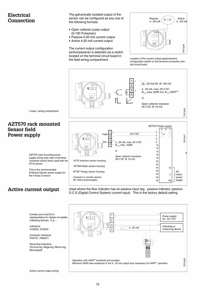
Active current output Used where the flow indicator has an passive input (eg. passive indicator, passiveD.C.S (Digital Control System) current input). This is the factory default setting.
The galvanically isolated output of thesensor can be configured as any one ofthe following formats:
• Open collector pulse output(0-100 Pulse/sec)
• Passive 4-20 mA current output• Active 4-20 mA current output
The current output configuration(active/passive) is selected via a switchlocated on the terminal circuit board inthe field wiring compartment.
Passive Active4...20 mA 4...20 mA
.
Location of the current output passive/activeconfiguration switch on the terminal connection prin-ted circuit board
Indicating ormeasuring device
IO
FMR1130:LIC0001Online1 >Group Select2 PV 8.7 m
HELP
FMR1130:LIC0001Online1 >Group Select2 PV 8.7 m
HELP
1
-4
1 +
2 -
3 +
-
+Power supply:20...30 V DC
-
+
Operation with HART handheld unit possibleMinimum 250R load resistance in the 4...20 mA output loop necessary for HART operation
®
®
4...20 mA
..
Contact your local E+Hrepresentative for details of suitableindicating devices: E.g. ...
Indicators:VU2520, VU2550
Computer interfacesFXA191, FMA671
Recording indicatorsChroma-log, Mega-log, Memo-log,Memograph
Active current output wiring
1
-4
1 +
2 -
3 +
20...30 Volt DC @ 130 mA
4...20 mA, max. 30 V DCR max. 500R incl. R HART
or
Open collector transistor30 V DC @ 10 mA
Load loadTM
. .
t-mass wiring compartment
AT70 Insertion sensor housing
AT70W Wafer sensor housing
AT70F Flange sensor housing
Compact or remote versionAC mains powersupply
ACmainspowersupply
AZT570 Power supply
24 V DC
SIG
PWR
d b z2
4
6
8
1012
14
16
18
20
22
24
26
28
30
32
L
--
++U
N
PE
1
-4
1 +
2 -
3 +4...20 mA, max. 30 V DCR max.: 500R
or
Open collector transistor30 V DC @ 10 mA
Load
.
..AZT570 rack mounting powersupply wiring (rear view of terminalconnector block) when used with theAT70 sensor
This is the recommendedEndress+Hauser power supply forthe t-mass S sensor
TI0
13y2
6T
I013
y05
TI0
13y2
9T
I013
y41
12
Passive current output
Open collectortransistor pulseoutput
Configuration
As an alternative to the current output, the t-mass signal output can be configured asa passive open collector transistor or active voltage pulse output for use with aself or externally powered electronic counter or DCS pulse input. If specified at thetime of order, the output will be configured as requested however the output can bere-configured in the field by a combination of switch settings and theprogramming matrix.
Note.The HARTTM communication feature of t-mass S cannot be used when theopen-collector transistor output is selected.
0123456
78
9
ABCD
EF
0123456
78
9
ABCD
EF
0123456
78
9
ABCD
EF
0123456
78
9
ABCD
EF
m / h3
m / h3
0123456
78
9
ABCD
EF
0123456
78
9
ABCD
EF
Mounting/ removing the local display moduleLocation of the pulse/current output configurationswitches in the main electronics compartment after
B
A
B
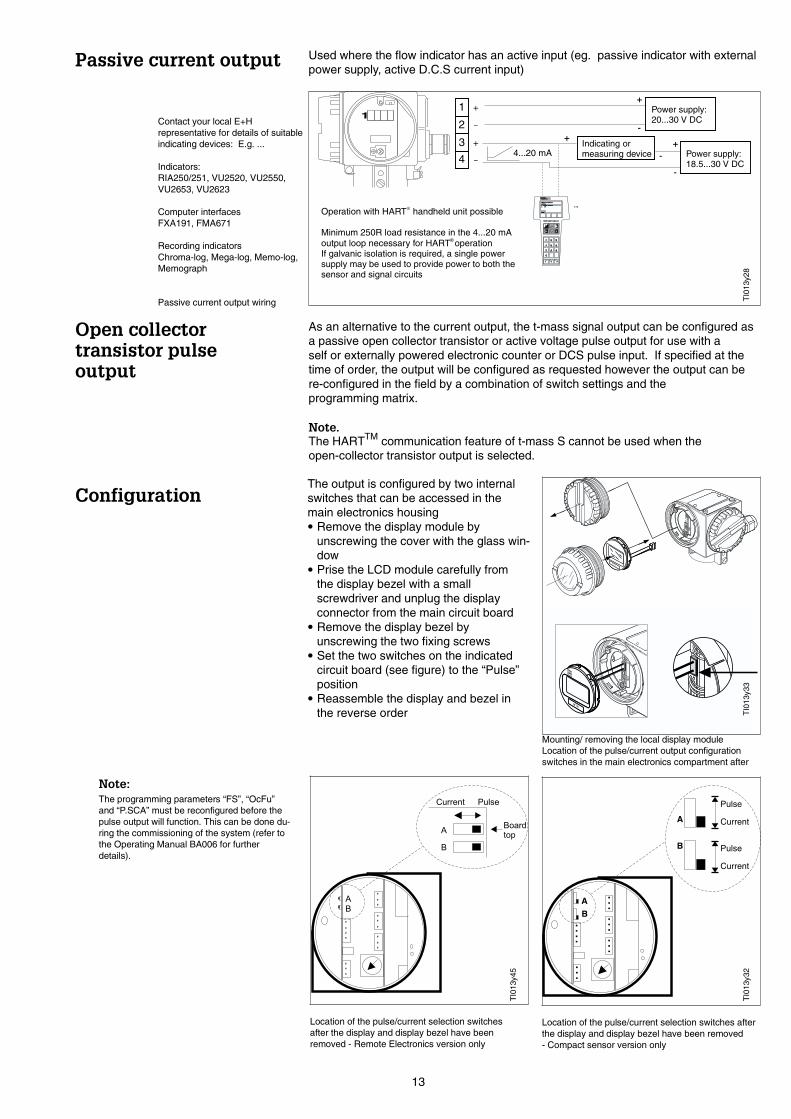
Current
Pulse
..
.
..
.
..
.
..
.
..
..
A
Current
Pulse
Location of the pulse/current selection switches afterthe display and display bezel have been removed- Compact sensor version only
-
+Power supply:18.5...30 V DC
Indicating ormeasuring device
IO
FMR1130:LIC0001Online1 >Group Select2 PV 8.7 m
HELP
FMR1130:LIC0001Online1 >Group Select2 PV 8.7 m
HELP
1
-4
1 +
2 -
3 +
-
+Power supply:20...30 V DC
-
+
Operation with HART handheld unit possible
Minimum 250R load resistance in the 4...20 mAoutput loop necessary for HART operation
®
®
4...20 mA
..
If galvanic isolation is required, a single powersupply may be used to provide power to both thesensor and signal circuits
Contact your local E+Hrepresentative for details of suitableindicating devices: E.g. ...
Indicators:RIA250/251, VU2520, VU2550,VU2653, VU2623
Computer interfacesFXA191, FMA671
Recording indicatorsChroma-log, Mega-log, Memo-log,Memograph
Passive current output wiring
Used where the flow indicator has an active input (eg. passive indicator with externalpower supply, active D.C.S current input)
TI0
13y3
3T
I013
y32
TI0
13y2
8
Location of the pulse/current selection switchesafter the display and display bezel have beenremoved - Remote Electronics version only
TI0
13y4
5
Note:The programming parameters “FS”, “OcFu”and “P.SCA” must be reconfigured before thepulse output will function. This can be done du-ring the commissioning of the system (refer tothe Operating Manual BA006 for furtherdetails).
The output is configured by two internalswitches that can be accessed in themain electronics housing• Remove the display module by
unscrewing the cover with the glass win-dow
• Prise the LCD module carefully fromthe display bezel with a smallscrewdriver and unplug the displayconnector from the main circuit board
• Remove the display bezel byunscrewing the two fixing screws
• Set the two switches on the indicatedcircuit board (see figure) to the “Pulse”position
• Reassemble the display and bezel inthe reverse order
13

For some counting devices the active pulse output may not be suitable due to avariety of reasons e.g incompatible on/off voltage thresholds, very low counter inputimpedance, high input current demand of the counter.The “passive” pulse output mode allows the open-collector output to be configured ina variety of different ways to suit the counting device.
Transistor is"switched off”
Transistor is"switched off”
Transistor is"switched on”
Pulse "off”
Pulse "on"
Pulse "on"
Pulse "off”
Passive Pulse Output
Active Pulse Output
>12 V DC
. .
Active and passive pulse output waveforms
Operation with HART handheld unit not possible with Pulse output®
Electroniccounting device
1
-4
1 +
2 -
3 +
-
+Power supply:20....30 V DC
-
+
..
Typical wiring configurationfor active pulse outputoperation with aself-powered electroniccounter
Passive Active4...20 mA 4...20 mA
.
Location of passive/active configuration switch onthe terminal connection printed circuit board
Pulse Output TypeOnce the above switches have been setto “Pulse”, the active/passive switch onthe terminal connector circuit boardconfigures the pulse output as either:
• Active: a voltage output from terminal3 that switches from an open circuitcondition when the pulse is “off” and>12 V when the pulse is “on” (relativeto terminal 4) This is the normalsetting for most electronic counters
• Passive: an open collector transistorthat has an internal 470R resistor in itscollector (see figure below). Thetransistor functions as a resistive“switch”
TI0
13y2
6
Internal sensor circuitry
Internal sensor circuitry
Passivepulseoutput
Activepulseoutput
-
-
+
+
1
2
3
4
1
2
3
4
470R
470R+
The basic AT70S open-collector output circuit
14
EMC/RFIrecommendations
Current outputloading - HARTTM
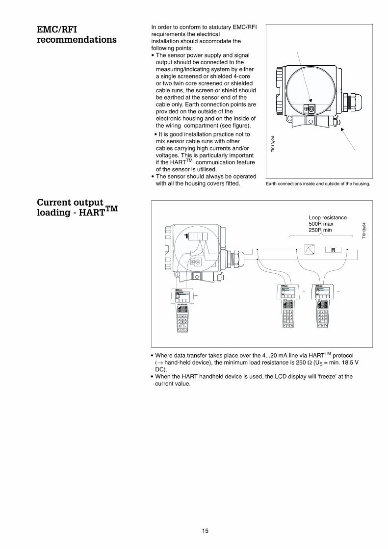
In order to conform to statutary EMC/RFIrequirements the electricalinstallation should accomodate thefollowing points:• The sensor power supply and signal
output should be connected to themeasuring/indicating system by eithera single screened or shielded 4-coreor two twin core screened or shieldedcable runs, the screen or shield shouldbe earthed at the sensor end of thecable only. Earth connection points areprovided on the outside of theelectronic housing and on the inside ofthe wiring compartment (see figure).
• It is good installation practice not tomix sensor cable runs with othercables carrying high currents and/orvoltages. This is particularly importantif the HARTTM communication featureof the sensor is utilised.
• The sensor should always be operatedwith all the housing covers fitted.
IO
FMR1130:LIC0001Online1 >Group Select2 PV 8.7 m
HELP
FMR1130:LIC0001Online1 >Group Select2 PV 8.7 m
HELP
IO
FMR1130:LIC0001Online1 > Matrix group sel.2 PV 8.7 m3/h3 Tot4 AO15 VFHELP
FMR1130:LIC0001Online1 > Matrix group sel.2 PV 8.7 m3/h3 Tot4 AO15 VFHELP
IO
FMR1130:LIC0001Online1 >Group Select2 PV 8.7 m
HELP
FMR1130:LIC0001Online1 >Group Select2 PV 8.7 m
HELP
IO
Loop resistance500R max250R min
1
. .R
• Where data transfer takes place over the 4...20 mA line via HARTTM protocol(→ hand-held device), the minimum load resistance is 250 Ω (US = min. 18.5 VDC).
• When the HART handheld device is used, the LCD display will ‘freeze’ at thecurrent value.
. .
Earth connections inside and outside of the housing.
TI0
13y2
4
TI0
13y3
4
15
Remote housingconfigurationand wiring
Hazardous areaoperation
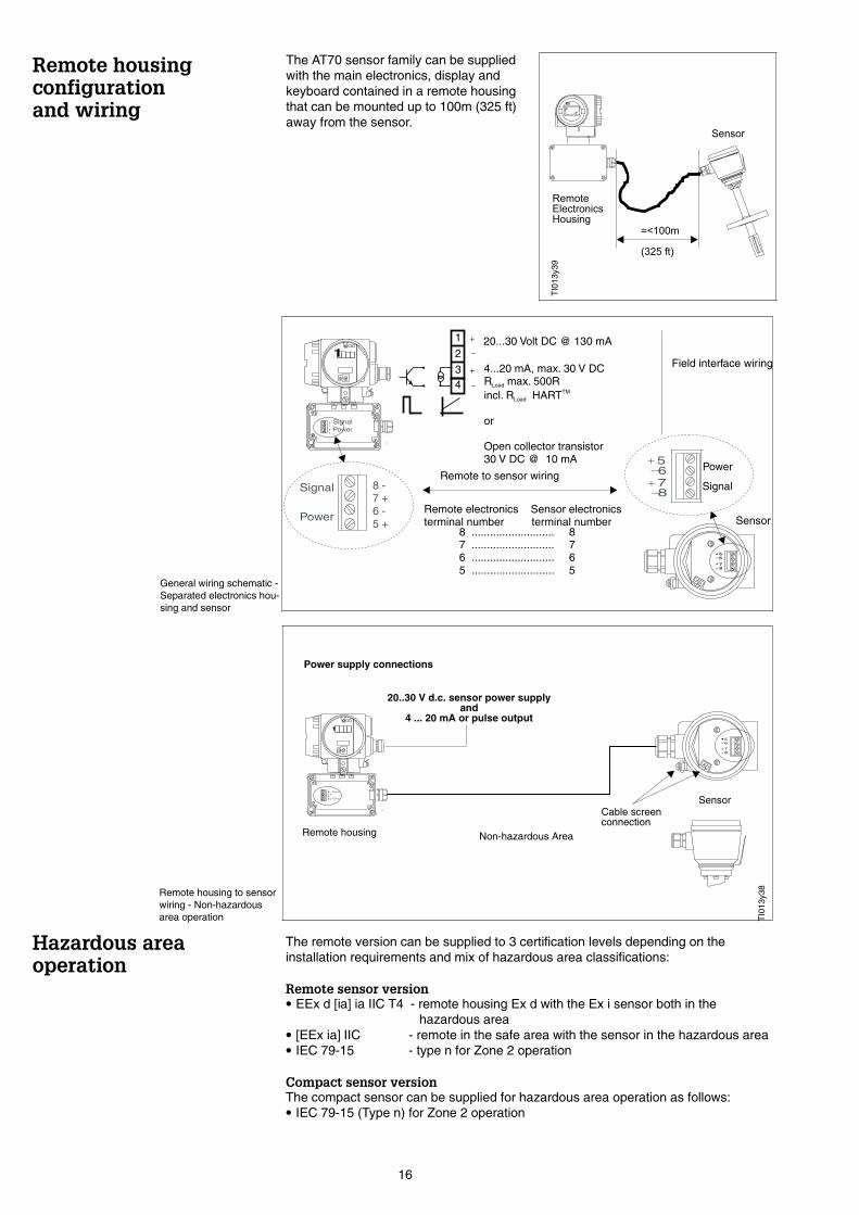
The AT70 sensor family can be suppliedwith the main electronics, display andkeyboard contained in a remote housingthat can be mounted up to 100m (325 ft)away from the sensor.
Cable screenconnection
8-7
6
+
-5+
1.
Power
Signal8 -7 +6 -5 +
Remote housing
Sensor
20..30 V d.c. sensor power supplyand
4 ... 20 mA or pulse output
. .
Non-hazardous Area
Power supply connections
Remote housing to sensorwiring - Non-hazardousarea operation
The remote version can be supplied to 3 certification levels depending on theinstallation requirements and mix of hazardous area classifications:
Remote sensor version• EEx d [ia] ia IIC T4 - remote housing Ex d with the Ex i sensor both in the
hazardous area• [EEx ia] IIC - remote in the safe area with the sensor in the hazardous area• IEC 79-15 - type n for Zone 2 operation
Compact sensor versionThe compact sensor can be supplied for hazardous area operation as follows:• IEC 79-15 (Type n) for Zone 2 operation
TI0
13y3
8
TI0
13y3
9
8-76
+-
5+ Power
Signal
Power
Signal 8 -7 +6 -5 +
4
1
2
3-
+
-
+
20...30 Volt DC @ 130 mA
4...20 mA, max. 30 V DCR max. 500Rincl. R HART
or
Open collector transistor30 V DC @ 10 mA
Load
LoadTM
8-7
6
+
-5+
1.
PowerSignal8 -
7 +6 -5 +
Remote electronics Sensor electronicsterminal number terminal number
8 ........................... 87 ........................... 76 ........................... 65 ........................... 5
Remote to sensor wiring
Field interface wiring
Sensor
General wiring schematic -Separated electronics hou-sing and sensor
16

8-7
6
+
-5+
1.
Power
Signal8 -
7 +
6 -
5 +
Non-hazardous Area
Remote housing
[Eex ia] IIC
Sensor
EEx ia IIC T4
Hazardous Area
20...30 V DC sensor power supply4...20 mA or pulse output
.
Ex ia connection
Remote housing to sensor wiring - Remote electronics in the non-hazardous area, sensor in the hazardous area
8-7
6
+
-5+
1.
Power
Signal8 -
7 +
6 -
5 +
Remote housingEEx d [ia] ia IIC T4
SensorEEx ia IIC T4
20...30 V DC sensor power supply4...20 mA or pulse output
. .
Non-hazardous Area
EEx d cable gland
Ex ia connection
Hazardous Area
Remote housing to sensor wiring- both the remote electronics and the sensor in the hazardous area
Remote electronics to sensor cable characteristics - EEx
Sensorcircuit
Exgas group
Maximumcable capacitance (nF)
Maximumcable inductance (mH)
Maximum L/R ratio(mH/R)
POWERconnections
IIAIIBIIC
34161281427
4.981.87
0.622
0.5760.2160.072
SIGNALconnections
IIAIIBIIC
63202370790
1760660220
43.216.25.4
Cable Specification (For the Remote Housing to Sensor wiring only)Power and Signal circuits• 4 core, overall screened - 4 x 0.5 mm2
• Conductor resistance per core - 40R/Kilometer• Capacitance - core/screen <=200 pF/metre
NoteThe maximum distance between the sensor and the remote electronics is 100m (325 ft).
TI0
13y3
7T
I013
y36
17
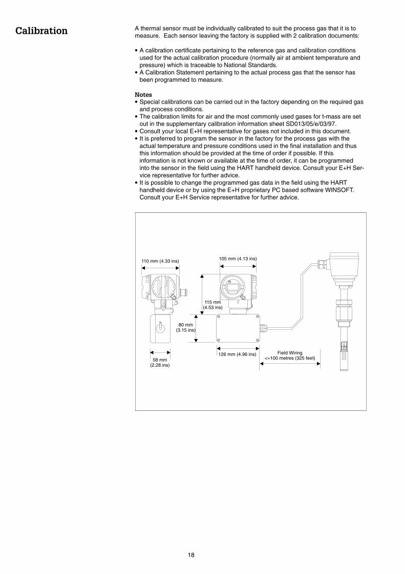
Calibration A thermal sensor must be individually calibrated to suit the process gas that it is tomeasure. Each sensor leaving the factory is supplied with 2 calibration documents:
• A calibration certificate pertaining to the reference gas and calibration conditionsused for the actual calibration procedure (normally air at ambient temperature andpressure) which is traceable to National Standards.
• A Calibration Statement pertaining to the actual process gas that the sensor hasbeen programmed to measure.
Notes• Special calibrations can be carried out in the factory depending on the required gas
and process conditions.• The calibration limits for air and the most commonly used gases for t-mass are set
out in the supplementary calibration information sheet SD013/05/e/03/97.• Consult your local E+H representative for gases not included in this document.• It is preferred to program the sensor in the factory for the process gas with the
actual temperature and pressure conditions used in the final installation and thusthis information should be provided at the time of order if possible. If thisinformation is not known or available at the time of order, it can be programmedinto the sensor in the field using the HART handheld device. Consult your E+H Ser-vice representative for further advice.
• It is possible to change the programmed gas data in the field using the HARThandheld device or by using the E+H proprietary PC based software WINSOFT.Consult your E+H Service representative for further advice.
110 mm (4.33 ins)
58 mm(2.28 ins)
126 mm (4.96 ins)
105 mm (4.13 ins)
115 mm(4.53 ins)
80 mm(3.15 ins)
Field Wiring<=100 metres (325 feet)
. .
18
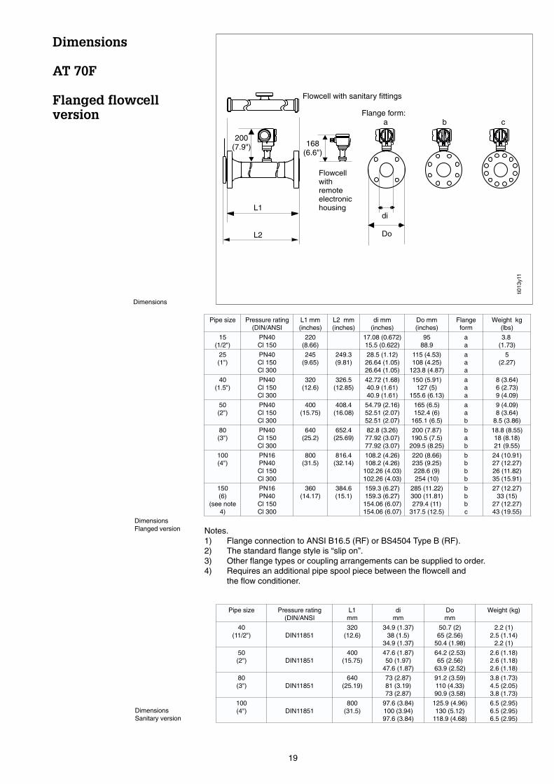
Dimensions
AT 70F
Flanged flowcellversion
.
168(6.6")
200(7.9")
Flowcellwithremoteelectronichousing
Flowcell with sanitary fittings
L1
L2
di
Do
Flange form:a b c
Dimensions
Pipe size Pressure rating(DIN/ANSI
L1 mm(inches)
L2 mm(inches)
di mm(inches)
Do mm(inches)
Flangeform
Weight kg(lbs)
15(1/2")
PN40Cl 150
220(8.66)
17.08 (0.672)15.5 (0.622)
9588.9
aa
3.8(1.73)
25(1")
PN40Cl 150Cl 300
245(9.65)
249.3(9.81)
28.5 (1.12)26.64 (1.05)26.64 (1.05)
115 (4.53)108 (4.25)
123.8 (4.87)
aaa
5(2.27)
40(1.5")
PN40Cl 150Cl 300
320(12.6)
326.5(12.85)
42.72 (1.68)40.9 (1.61)40.9 (1.61)
150 (5.91)127 (5)
155.6 (6.13)
aaa
8 (3.64)6 (2.73)9 (4.09)
50(2")
PN40Cl 150Cl 300
400(15.75)
408.4(16.08)
54.79 (2.16)52.51 (2.07)52.51 (2.07)
165 (6.5)152.4 (6)
165.1 (6.5)
aab
9 (4.09)8 (3.64)
8.5 (3.86)
80(3")
PN40Cl 150Cl 300
640(25.2)
652.4(25.69)
82.8 (3.26)77.92 (3.07)77.92 (3.07)
200 (7.87)190.5 (7.5)
209.5 (8.25)
bab
18.8 (8.55)18 (8.18)21 (9.55)
100(4")
PN16PN40Cl 150Cl 300
800(31.5)
816.4(32.14)
108.2 (4.26)108.2 (4.26)
102.26 (4.03)102.26 (4.03)
220 (8.66)235 (9.25)228.6 (9)254 (10)
bbbb
24 (10.91)27 (12.27)26 (11.82)35 (15.91)
150(6)
(see note4)
PN16PN40Cl 150Cl 300
360(14.17)
384.6(15.1)
159.3 (6.27)159.3 (6.27)
154.06 (6.07)154.06 (6.07)
285 (11.22)300 (11.81)279.4 (11)
317.5 (12.5)
bbbc
27 (12.27)33 (15)
27 (12.27)43 (19.55)
Notes.1) Flange connection to ANSI B16.5 (RF) or BS4504 Type B (RF).2) The standard flange style is “slip on”.3) Other flange types or coupling arrangements can be supplied to order.4) Requires an additional pipe spool piece between the flowcell and
the flow conditioner.
DimensionsFlanged version
Pipe size Pressure rating(DIN/ANSI
L1mm
dimm
Domm
Weight (kg)
40(11/2") DIN11851
320(12.6)
34.9 (1.37)38 (1.5)
34.9 (1.37)
50.7 (2)65 (2.56)
50.4 (1.98)
2.2 (1)2.5 (1.14)
2.2 (1)
50(2") DIN11851
400(15.75)
47.6 (1.87)50 (1.97)
47.6 (1.87)
64.2 (2.53)65 (2.56)
63.9 (2.52)
2.6 (1.18)2.6 (1.18)2.6 (1.18)
80(3") DIN11851
640(25.19)
73 (2.87)81 (3.19)73 (2.87)
91.2 (3.59)110 (4.33)90.9 (3.58)
3.8 (1.73)4.5 (2.05)3.8 (1.73)
100(4") DIN11851
800(31.5)
97.6 (3.84)100 (3.94)97.6 (3.84)
125.9 (4.96)130 (5.12)
118.9 (4.68)
6.5 (2.95)6.5 (2.95)6.5 (2.95)
DimensionsSanitary version
ti013
y11
19
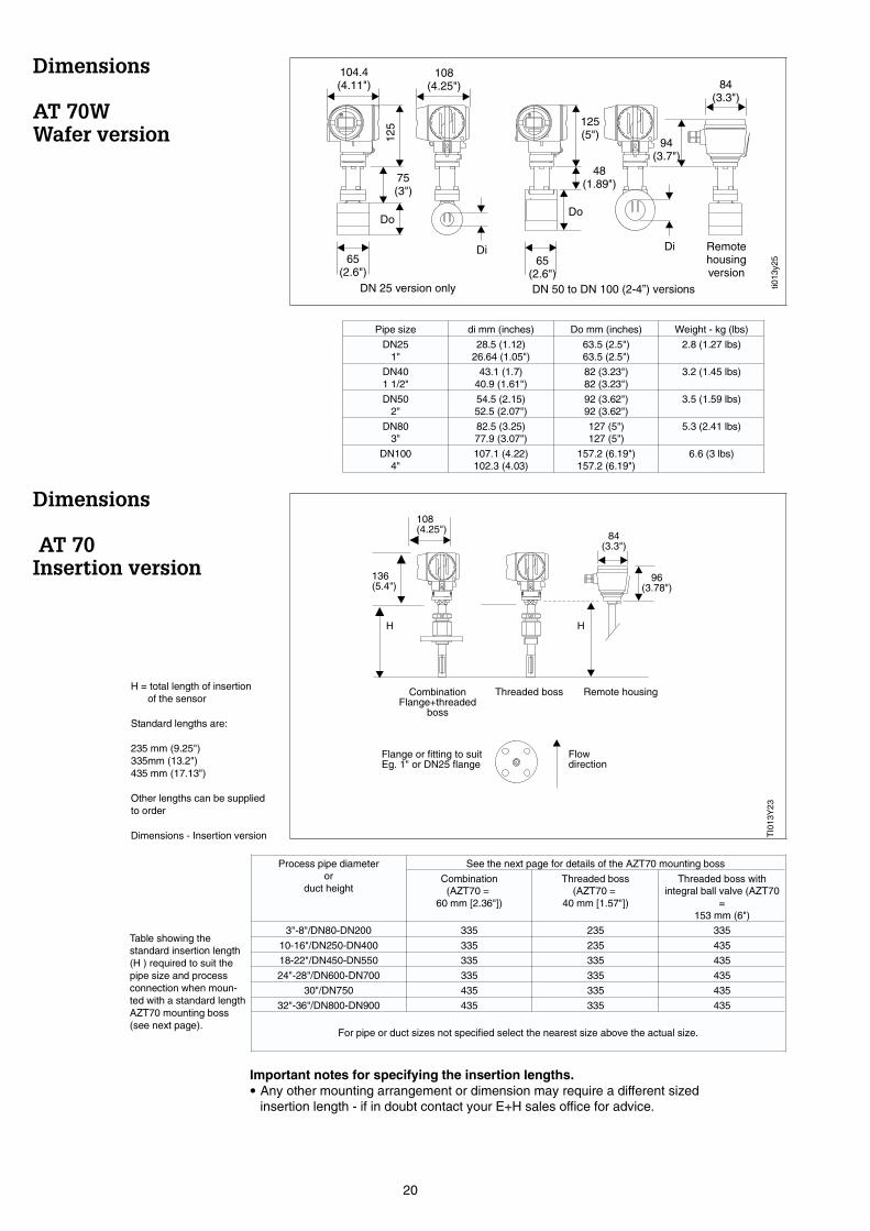
Dimensions
AT 70WWafer version
Dimensions
AT 70Insertion version
Pipe size di mm (inches) Do mm (inches) Weight - kg (lbs)
DN251"
28.5 (1.12)26.64 (1.05")
63.5 (2.5")63.5 (2.5")
2.8 (1.27 lbs)
DN401 1/2"
43.1 (1.7)40.9 (1.61")
82 (3.23")82 (3.23")
3.2 (1.45 lbs)
DN502"
54.5 (2.15)52.5 (2.07")
92 (3.62")92 (3.62")
3.5 (1.59 lbs)
DN803"
82.5 (3.25)77.9 (3.07")
127 (5")127 (5")
5.3 (2.41 lbs)
DN1004"
107.1 (4.22)102.3 (4.03)
157.2 (6.19")157.2 (6.19")
6.6 (3 lbs)
65(2.6")
. .
108(4.25")
104.4(4.11")
125
75(3")
Do
65(2.6")
Di
84(3.3")
94(3.7")
Remotehousingversion
Di
Do
125(5")
48(1.89")
DN 50 to DN 100 (2-4”) versionsDN 25 version only
96(3.78")
84(3.3")
108(4.25")
136(5.4")
H H
CombinationFlange+threaded
boss
Threaded boss Remote housing
Flange or fitting to suitEg. 1" or DN25 flange
Flowdirection
..
H = total length of insertionof the sensor
Standard lengths are:
235 mm (9.25")335mm (13.2")435 mm (17.13")
Other lengths can be suppliedto order
Dimensions - Insertion version TI0
13Y
23ti0
13y2
5
Process pipe diameteror
duct height
See the next page for details of the AZT70 mounting boss
Combination(AZT70 =
60 mm [2.36"])
Threaded boss(AZT70 =
40 mm [1.57"])
Threaded boss withintegral ball valve (AZT70
=153 mm (6")
3"-8"/DN80-DN200 335 235 335
10-16"/DN250-DN400 335 235 435
18-22"/DN450-DN550 335 335 435
24"-28"/DN600-DN700 335 335 435
30"/DN750 435 335 435
32"-36"/DN800-DN900 435 335 435
For pipe or duct sizes not specified select the nearest size above the actual size.
Important notes for specifying the insertion lengths.• Any other mounting arrangement or dimension may require a different sized
insertion length - if in doubt contact your E+H sales office for advice.
Table showing thestandard insertion length(H ) required to suit thepipe size and processconnection when moun-ted with a standard lengthAZT70 mounting boss(see next page).
20
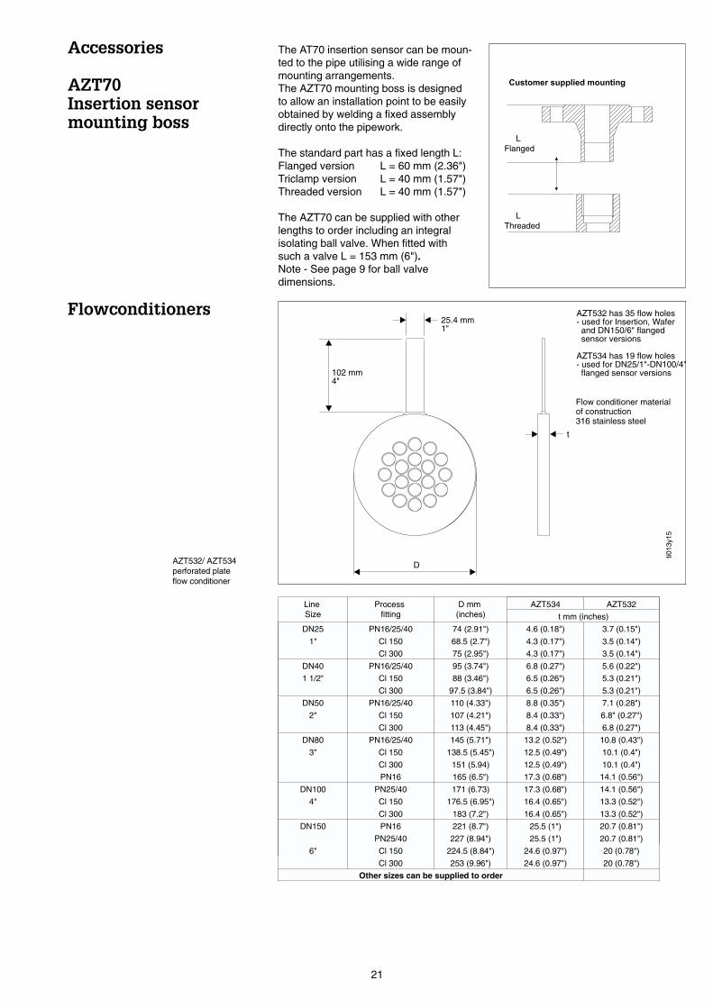
Accessories
AZT70Insertion sensormounting boss
Flowconditioners
AZT534 has 19 flow holes- used for DN25/1"-DN100/4"
flanged sensor versions
AZT532 has 35 flow holes- used for Insertion, Wafer
and DN150/6" flangedsensor versions
25.4 mm1"
t
102 mm4"
D
.Flow conditioner materialof construction316 stainless steel
AZT532/ AZT534perforated plateflow conditioner
ti013
y15
The AT70 insertion sensor can be moun-ted to the pipe utilising a wide range ofmounting arrangements.The AZT70 mounting boss is designedto allow an installation point to be easilyobtained by welding a fixed assemblydirectly onto the pipework.
The standard part has a fixed length L:Flanged version L = 60 mm (2.36")Triclamp version L = 40 mm (1.57")Threaded version L = 40 mm (1.57")
The AZT70 can be supplied with otherlengths to order including an integralisolating ball valve. When fitted withsuch a valve L = 153 mm (6").Note - See page 9 for ball valvedimensions.
LineSize
Processfitting
D mm(inches)
AZT534 AZT532
t mm (inches)
DN25 PN16/25/40 74 (2.91") 4.6 (0.18") 3.7 (0.15")
1" Cl 150 68.5 (2.7") 4.3 (0.17") 3.5 (0.14")
Cl 300 75 (2.95") 4.3 (0.17") 3.5 (0.14")
DN40 PN16/25/40 95 (3.74") 6.8 (0.27") 5.6 (0.22")
1 1/2" Cl 150 88 (3.46") 6.5 (0.26") 5.3 (0.21")
Cl 300 97.5 (3.84") 6.5 (0.26") 5.3 (0.21")
DN50 PN16/25/40 110 (4.33") 8.8 (0.35") 7.1 (0.28")
2" Cl 150 107 (4.21") 8.4 (0.33") 6.8" (0.27")
Cl 300 113 (4.45") 8.4 (0.33") 6.8 (0.27")
DN80 PN16/25/40 145 (5.71") 13.2 (0.52") 10.8 (0.43")
3" Cl 150 138.5 (5.45") 12.5 (0.49") 10.1 (0.4")
Cl 300 151 (5.94) 12.5 (0.49") 10.1 (0.4")
PN16 165 (6.5") 17.3 (0.68") 14.1 (0.56")
DN100 PN25/40 171 (6.73) 17.3 (0.68") 14.1 (0.56")
4" Cl 150 176.5 (6.95") 16.4 (0.65") 13.3 (0.52")
Cl 300 183 (7.2") 16.4 (0.65") 13.3 (0.52")
DN150 PN16 221 (8.7") 25.5 (1") 20.7 (0.81")
PN25/40 227 (8.94") 25.5 (1") 20.7 (0.81")
6" Cl 150 224.5 (8.84") 24.6 (0.97") 20 (0.78")
Cl 300 253 (9.96") 24.6 (0.97") 20 (0.78")
Other sizes can be supplied to order
LFlanged
LThreaded
21

Technical Data
AT 70W: wafer flowcell
AT 70F: flanged flowcell
AT 70: insertion probe
Process Limits
Nominal diameters: 70W: DN25 ... 100 DIN1" ... 4" ANSI
70F: DN15 ... 150 DIN1/2" ... 6" ANSI
70: DN80 ... 1000 DIN3" ... 39" ANSI
Nominal pressure: 70W/F: PN40 (DIN2501)70: PN16 (DIN2501)
Cl.150 (ANSI B16.5)
Permissible processtemperature:
70/W/F: -10 ... +100 oC14 ... +212 oF
Materials-wetted Parts:
meter body: SS316optional Hastelloy (pending)
transducers: SS316, Hastelloy C276
transducer seals: viton, optional kalrez, EPDM
Materials - mounting set: 70W only
centering rings:mounting bolts/hex nuts:washers:
2 pieces, stainless steel 1.43011.7258 galvanisedgalvanised steel
Housing
Housing material cast aluminum, painted
Protection type IP 65 (DN 40050)
Ambient temperature -30...+80 °C (-22...+176 °F)
Display Liquid crystal display; 4 numeric character with decimalpoint plus bargraph in %of current output full scale
Cable glands PG 13.5 standard, others to order
Electrical
Electromagneticcompatibility (EMC)
IEC 801 part 3: E = 10 V/m (30 MHz...1GHz);
Power supply 20...30 V DC
Power consumption < 3 W
Galvanic isolation Between process and outputs: 500 V
Open collector output Imax = 10 mA, Umax = 30 V, P = 300mWScalable pulse output up to 100 Pulse/sec,
Current output 4...20 mA analogue current output,full-scale value and time constant may be set from thekeyboard(minimum T = 1.5 secs @ 63%)
Data storage Integral non-volatile memory note 4
Communication SMART technology, HARTTM protocol via current output
22
Technical Data
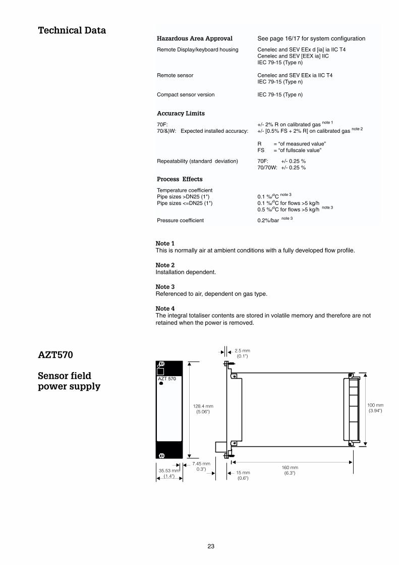
AZT570
Sensor fieldpower supply
Hazardous Area Approval See page 16/17 for system configuration
Remote Display/keyboard housing
Remote sensor
Compact sensor version
Cenelec and SEV EEx d [ia] ia IIC T4Cenelec and SEV [EEX ia] IICIEC 79-15 (Type n)
Cenelec and SEV EEx ia IIC T4IEC 79-15 (Type n)
IEC 79-15 (Type n)
Accuracy Limits
70F:70/&)W: Expected installed accuracy:
+/- 2% R on calibrated gas note 1
+/- [0.5% FS + 2% R] on calibrated gas note 2
R = “of measured value”FS = “of fullscale value”
Repeatability (standard deviation) 70F: +/- 0.25 %70/70W: +/- 0.25 %
Process Effects
Temperature coefficientPipe sizes >DN25 (1")Pipe sizes <=DN25 (1")
0.1 %/oC note 3
0.1 %/oC for flows >5 kg/h0.5 %/oC for flows >5 kg/h note 3
Pressure coefficient 0.2%/bar note 3
Note 1This is normally air at ambient conditions with a fully developed flow profile.
Note 2Installation dependent.
Note 3Referenced to air, dependent on gas type.
Note 4The integral totaliser contents are stored in volatile memory and therefore are notretained when the power is removed.
100 mm
(3.94")
2.5 mm
(0.1")
160 mm
(6.3")
7.45 mm
0.3")35.53 mm
(1.4")
128.4 mm
(5.06")
15 mm
(0.6")
23
AZT570
Sensor fieldpower supply
SupplementaryDocumentation
System Information t-mass S (SI 0150/06/e/Mar97)AT70 installation and operating instructions (BA 006/05/e/02/98Meter flow ranges (SD013/05/e/03/97))
Subject to modification
Printed in the United Kingdom by Blackburns of Bolton Ltd
AustraliaALSTOM Australia LtdMeasurement & Control44-46 Mandarin StreetVillawood N.S.W 2163AustraliaTel: 2 97 22 4777Fax: 2 97 22 4883
Belgium/LuxembourgEndress+Hauser S.A/N.VRue Carli Straat 131140 Bruxelles/BrusselsTel: 22 48 0600Fax: 22 48 0553
CanadaEndress+Hauser Ltd.1440 Grahams LaneUnit No 1, Burlington, OntarioTel: (905) 681 9292Fax: (905) 681 9444
Endress+Hauser Ltée6800 Côte de Lièsse No 301Ville St Laurent, Quebec, H4T 2A7Tel: (514) 733 0254Fax: (514) 733 2924
DenmarkEndress+Hauser ApSPoppelgårdvej 10-122860 SoborgTel: 70 131132Fax: 70 132133
EireFlomeaco Co. LtdIndustrial Instrumentation CentreClane Business ParkClaneCounty KildareTel: 045 868615Fax:045 868182
FinlandEndress+Hauser OyMikkelänkallio 3FIN-02770 EspooTel: 98 859 6155Fax: 98 859 6055
Great BritainUK Head Office & Production CentreEndress + Hauser LtdFloats RoadManchesterM23 9NFTel: 0161 286 5000Fax: 0161 998 1841
GlasgowTel: 0141 248 6234
NetherlandsEndress+Hauser B.VPostbus 51021410 AC NaardenTel: 03569 58611Fax: 03569 58825
New ZealandEMC Industrial Group LtdPO Box 101 444North Shore Mail Centre56 Tarndale GroveAlbanyAucklandTel: 9 415 5110Fax: 9 415 5115
NorwayEndress+Hauser A/SPostboks 623402 LierskogenTel: 03285 9850Fax: 03285 9851
SingaporeEndress+Hauser (S.E.A) Pte. Ltd1 International Business Park# 01-11/12 The SynergySingapore 609917Tel: 065 566 8222Fax: 065 566 6848
SwitzerlandEndress+Hauser AGStemenhofstrasse 214153 Reinach/BL1Tel: 061 715 75 75Fax: 061 711 16 50
South AfricaEndress + Hauser Pty. Ltd5 Commerce Crescent WestEastgate Ext. 13P.O. Box 783 996Sandton 2146Tel: 011 444 1386Fax: 011 444 1977
ThailandEndress+Hauser (Thailand) Ltd89/15 Moo 9Vipavadi-Rangsit RoadTalard-Bangkhen, DonmuangBangkok 10210Tel: 66 2 996 7811-20Fax: 66 2 996 7810
SwedenEndress+Hauser ABBergkallavagen 24 ABox 700619207 SollentunaTel: 08 626 1600Fax: 08 626 9477
USAEndress+Hauser Inc2350 Endress PlacePO Box 246, GreenwoodIndiana, 46143Tel: (317) 535 7138Fax: (317) 535 8498
Power supply90/110/115/120/220/230/240V AC±15%, 50/60HzIntegrated mains fuse90/110/115/120V AC - 125mA slow-blow220/230/240V AC - 63mA slow-blow
Power output24 V DC field power to single AT70 sensor
Permissible ambient temperature-10oC...+65oC (do not install in direct sunlight)
Storage temperature-20oC...+85oC
Weight:Approx 0.5kg
Mechanical DesignRacksyst plug-in board in accordance withDIN41494, part 5, d=160 mm (6.3"),h=100 mm (4") (Eurocard standard).
Male electrical connectorMulti-pin, compatible in accordance withDIN41612 part 3, type F (32 pin).
Width7 pitch units (35mm [1.28"]).
ProtectionFront panel to IP20
ConformityCE mark compliance with electromagneticcompatibility according to EN50081-1:1992and EN50082-1:1992
24