thermal performance of high temperature titanium—water ... · graphic presentations. ... thermal...
TRANSCRIPT

James L. Sanzi
Sest, Inc., Middleburg Heights, Ohio
Thermal Performance of High TemperatureTitanium—Water Heat Pipes by MultipleHeat Pipe Manufacturers
NASA/CR—2007-214820
June 2007
https://ntrs.nasa.gov/search.jsp?R=20070026345 2018-08-29T00:56:02+00:00Z

NASA STI Program . . . in Profile
Since its founding, NASA has been dedicated to the
advancement of aeronautics and space science. The
NASA Scientific and Technical Information (STI)
program plays a key part in helping NASA maintain
this important role.
The NASA STI Program operates under the auspices
of the Agency Chief Information Officer. It collects,
organizes, provides for archiving, and disseminates
NASA’s STI. The NASA STI program provides access
to the NASA Aeronautics and Space Database and its
public interface, the NASA Technical Reports Server,
thus providing one of the largest collections of
aeronautical and space science STI in the world.
Results are published in both non-NASA channels and
by NASA in the NASA STI Report Series, which
includes the following report types:
• TECHNICAL PUBLICATION. Reports of
completed research or a major significant phase
of research that present the results of NASA
programs and include extensive data or theoretical
analysis. Includes compilations of significant
scientific and technical data and information
deemed to be of continuing reference value.
NASA counterpart of peer-reviewed formal
professional papers but has less stringent
limitations on manuscript length and extent of
graphic presentations.
• TECHNICAL MEMORANDUM. Scientific
and technical findings that are preliminary or
of specialized interest, e.g., quick release
reports, working papers, and bibliographies that
contain minimal annotation. Does not contain
extensive analysis.
• CONTRACTOR REPORT. Scientific and
technical findings by NASA-sponsored
contractors and grantees.
• CONFERENCE PUBLICATION. Collected
papers from scientific and technical
conferences, symposia, seminars, or other
meetings sponsored or cosponsored by NASA.
• SPECIAL PUBLICATION. Scientific,
technical, or historical information from
NASA programs, projects, and missions, often
concerned with subjects having substantial
public interest.
• TECHNICAL TRANSLATION. English-
language translations of foreign scientific and
technical material pertinent to NASA’s mission.
Specialized services also include creating custom
thesauri, building customized databases, organizing
and publishing research results.
For more information about the NASA STI
program, see the following:
• Access the NASA STI program home page at
http://www.sti.nasa.gov
• E-mail your question via the Internet to
• Fax your question to the NASA STI Help Desk
at 301–621–0134
• Telephone the NASA STI Help Desk at
301–621–0390
• Write to:
NASA Center for AeroSpace Information (CASI)
7115 Standard Drive
Hanover, MD 21076–1320

James L. Sanzi
Sest, Inc., Middleburg Heights, Ohio
Thermal Performance of High TemperatureTitanium—Water Heat Pipes by MultipleHeat Pipe Manufacturers
NASA/CR—2007-214820
June 2007
National Aeronautics and
Space Administration
Glenn Research Center
Cleveland, Ohio 44135
Prepared under Contract NNC05BA21B
Prepared for the
Space Technology and Applications International Forum (STAIF–2007)
sponsored by the Institute of Space and Nuclear Power Studies at the University of New Mexico
Albuquerque, New Mexico, February 11–15, 2007

Acknowledgments
This work was carried out at NASA Glenn Research Center at Lewis field and was supported by
Exploration Systems/Prometheus.
Available from
NASA Center for Aerospace Information
7115 Standard Drive
Hanover, MD 21076–1320
National Technical Information Service
5285 Port Royal Road
Springfield, VA 22161
Available electronically at http://gltrs.grc.nasa.gov
Level of Review: This material has been technically reviewed by NASA expert reviewer(s).
Trade names and trademarks are used in this report for identification
only. Their usage does not constitute an official endorsement,
either expressed or implied, by the National Aeronautics and
Space Administration.
NASA/CR—2007-214820 1
Thermal Performance of High Temperature Titanium—Water Heat Pipes by Multiple Heat Pipe Manufacturers
James L. Sanzi
Sest, Inc. Middleburg Heights, Ohio 44130
Abstract Titanium–water heat pipes are being investigated for use in heat rejection systems for lunar and Mars
fission surface power systems. Heat pipes provide an efficient and reliable means to transfer heat to a radiator heat rejection system. NASA Glenn Research Center (GRC) requisitioned nine titanium water heat pipes from three vendors. Each vendor supplied three heat pipes 1.25 cm diameter by 1.1 meter long with each vendor selecting a different wick design. Each of the three heat pipes is slightly different in construction. Additional specifications for the heat pipes included 500 K nominal operating temperature, light weight, and freeze tolerance. The heat pipes were performance tested gravity-aided, in the horizontal position and at elevations against gravity at 450 and 500 K. Performance of the three heat pipes is compared. The heat pipe data will be used to verify models of heat pipe radiators that will be used in future space exploration missions.
Introduction Heat rejection systems are under study by NASA for various nuclear electric power and surface
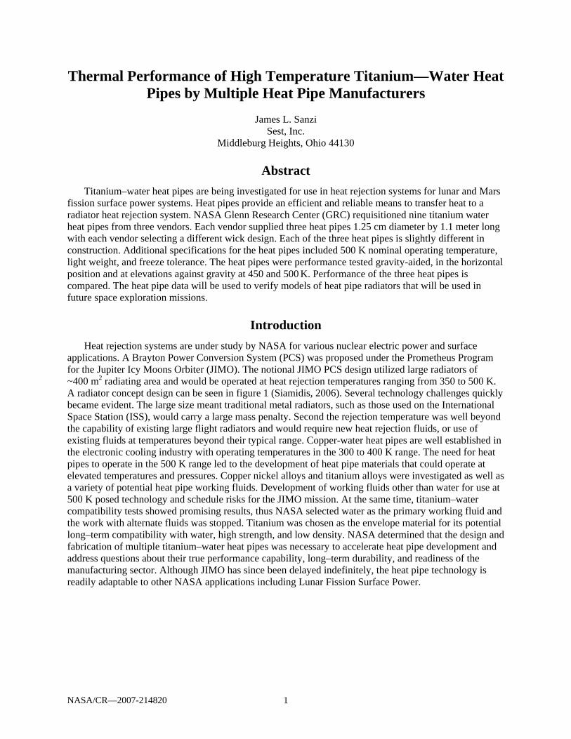
applications. A Brayton Power Conversion System (PCS) was proposed under the Prometheus Program for the Jupiter Icy Moons Orbiter (JIMO). The notional JIMO PCS design utilized large radiators of ~400 m2 radiating area and would be operated at heat rejection temperatures ranging from 350 to 500 K. A radiator concept design can be seen in figure 1 (Siamidis, 2006). Several technology challenges quickly became evident. The large size meant traditional metal radiators, such as those used on the International Space Station (ISS), would carry a large mass penalty. Second the rejection temperature was well beyond the capability of existing large flight radiators and would require new heat rejection fluids, or use of existing fluids at temperatures beyond their typical range. Copper-water heat pipes are well established in the electronic cooling industry with operating temperatures in the 300 to 400 K range. The need for heat pipes to operate in the 500 K range led to the development of heat pipe materials that could operate at elevated temperatures and pressures. Copper nickel alloys and titanium alloys were investigated as well as a variety of potential heat pipe working fluids. Development of working fluids other than water for use at 500 K posed technology and schedule risks for the JIMO mission. At the same time, titanium–water compatibility tests showed promising results, thus NASA selected water as the primary working fluid and the work with alternate fluids was stopped. Titanium was chosen as the envelope material for its potential long–term compatibility with water, high strength, and low density. NASA determined that the design and fabrication of multiple titanium–water heat pipes was necessary to accelerate heat pipe development and address questions about their true performance capability, long–term durability, and readiness of the manufacturing sector. Although JIMO has since been delayed indefinitely, the heat pipe technology is readily adaptable to other NASA applications including Lunar Fission Surface Power.
NASA/CR—2007-214820 2
Figure 1.—Heat pipes integrated in heat rejection radiator panel.
Design and Testing NASA requested quotes from three heat pipe vendors to design and build three titanium-water heat
pipes each. All nine were delivered to the Glenn Research Center in the Spring of 2006. NASA specified the overall heat pipe dimensions and left all other details, such as wick configuration, for each vendor to address. Concurrent with this effort, a heat pipe test bed was designed and built at Glenn research center through an in-house effort. The following describes features of the test bed and the delivered heat pipes.
An available optics bench at NASA Glenn Research Center made an ideal surface for testing heat pipes. The bench is 122 by 182 cm and the grid of 3220 tapped holes every 2.54 cm gives the flexibility to perform a variety of test configurations. Nine titanium-water heat pipes are installed in their calorimeters on the optics bench as shown in figure 2. The heat pipes are supported by a post holder which has a 1.25 cm threaded rod with a quick-thread nut for adjusting the height and inclination. This permits performance testing of the heat pipes horizontally and against gravity. There is a machined saddle to support a horizontal ceramic insulating tube to minimize the conduction heat loss as seen in figure 2.
The heat pipe evaporator is heated through a 20 cm long, split aluminum block hose clamped to the evaporator. Heat is provide to the block with four cartridge heaters inserted into the aluminum. Each cartridge heater produces 350 W at 120 V, giving a total capacity of 1400 W heating per heat pipe, about double the anticipated need. The heater block is insulated with mineral wool and wrapped in aluminum foil to reduce thermal losses as seen in figure 3. The thermal loss of the heater block was measured to be 23.1 W at an operating temperature of 500 K by using calibrated volt and amp meters.
A Neslab HX-540 recirculating chiller was installed. The HX-540 recirculating chiller is designed to provide a continuous flow of a 50/50 mixture of ethylene glycol/water cooling fluid at a constant temperature to the gas-gap calorimeter manifold as seen in figures 4 and 5. The chiller consist of a water cooled refrigeration system, stainless steel reservoir, recirculating pump, and a microprocessor controller. An important characteristic of the chiller is its ability to track a set temperature virtually independent of changing heat loads. The cooling loop has a check valve to prevent back flow and flowmeter to visually verify flow to the calorimeters. The calorimeter is fabricated from 5 cm square aluminum 90 cm long and has a gun drilled 1.6 cm hole through the center and 0.6 cm gun drilled holes in the corners for the coolant fluid. The heat pipe calorimeters each have an individual positive displacement gear flowmeter as seen in figure 5. The principle of operation is reversed; instead of the gears driving the medium, the medium drives the gears. A non-intrusive hall-effect sensor detects the movement of the gear and as each gear tooth passes the sensor a square wave pulse is produced and a discrete volume of liquid is measured. The

NASA/CR—2007-214820 3
Figure 2.—Optic test bench and Figure 3.—Heat pipe test setup. adjustable supports.
Figure 4.—Coolant manifold. Figure 5.—Calorimeter flowmeter. resulting pulse train is proportional to the actual flow rate and provides a highly accurate representation of the fluid flow. Two Resistance Temperature Detectors (RTDs) were used to measure the coolant temperature.
Heat Pipe Designs A heat pipe in its simplest form is a passive two-phase heat transfer device in a sealed tube as shown
in figure 6 (Devarakonda, 2006). The evaporator region of the heat pipe is in thermal contact with a heat source. The envelope of the heat pipe is typically made of a high conductivity material and transports the heat to the liquid inside. The only fluid inside the heat pipe is the working fluid in thermodynamic equilibrium with its own vapor. Liquid in the evaporator region evaporates to vapor and is transported to the other end of the tube where the vapor condenses to release the latent heat to the tube wall. The condensation process can be augmented by various external means like provision of fins. The condensed fluid is transported back to the evaporator region by the capillary action of a wick that lines the inner wall of the tube, hence the device is passive. All vendors completed preliminary design and heat pipe performance predictions for a titanium-water heat pipe that employs each manufacturer’s wick structure incorporated with the specifications provided by NASA–GRC as shown in table 1.
Calorimeter
Heater block
Threaded rod
Optics bench Power controller
Liquid flow manifold
Gas flowmeters
Calorimeter flowmeter

NASA/CR—2007-214820 4
Figure 6.—Illustration of a capillary two-phase heat transfer device-a heat pipe.
TABLE 1.—NASA GRC HEAT PIPE SPECIFICATIONS Nominal operating temperature (K) 500 Operating temperature range (K) 310 to 550 Heat pipe heat transfer capability (K) Maximize power at 500 Heat pipe outer diameter (cm) 1.27 Wall thickness Meet ASME section VIII boiler and pressure vessel code Heat pipe evaporator length (cm) 25 Heat pipe adiabatic length (cm) 0 Heat pipe condenser length (cm) 90 Heat pipe mass Minimize Wick structure To be specified by vendor Heat pipe closure Titanium valve Heat pipe materials and construction Titanium grade 2 Proof pressure test Design calculations and validation
Heat pipe Manufacturer “A” supplied three titanium heat pipes with an axial groove felt metal wick
(Rosenfeld, 2006). The wick was assembled using titanium felt wick material. Figure 7 shows an end view of a section of wick prior to insertion into a heat pipe envelope. Figure 8 shows a cross sectional view of the assembled wick structure after installation into the envelope. Each heat pipe from Manufacturer “A” is different in the evaporator or has different groove geometry. Heat pipe 1 has a trapezoidal axial groove felt metal wick in the evaporator and condenser region. Heat pipe 2 has a trapezoidal axial groove felt metal wick in the condenser and a screen covered trapezoidal axial groove felt metal wick in the evaporator. Heat pipe 3 has a trapezoidal axial groove felt metal wick in the condenser and a narrow groove felt metal evaporator.
Heat pipe Manufacturer “B” supplied three titanium heat pipes with a machined axial groove wick (Dussinger, 2006). Each axial groove heat pipe has a different groove geometry and different number of grooves as shown in figure 9.
Heat pipe Manufacturer “C” supplied 3 titanium heat pipes with screen-artery wicks (Nikitkin, 2006). The evaporator section in each heat pipe is different. Heat pipe 1 has a circumferentially machined groove wick in the evaporator with open - ended axial arteries the length of the heat pipe. Heat pipe 2 has a circumferential machined groove wick not as deep in the evaporator as in heat pipe 1 and open-ended axial arteries the length of the heat pipe. Heat pipe 3 has a screen circumferential wick in the evaporator with open-ended axial arteries the length of the heat pipe. All the heat pipes have 5 open axial arteries. A typical representation is shown in figure 10.

NASA/CR—2007-214820 5
Figure 7.—Felt metal wick from Manufacturer “A”. Figure 8.—Cross section of axial groove wick from Manufacturer “A”.
Figure 9.—Machined solid axial groove wick from Manufacturer “B”.
Figure 10.—Artery wick configuration from Manufacturer “C”.
Titanium Heat Pipe Wall
Screen Wick Artery
19 Grooves
17 Grooves 23 Grooves

NASA/CR—2007-214820 6
Test Layout Figure 11 shows the location of the various thermocouples along the length of the heat pipe on the
evaporator region while figure 12 shows the same for the condenser region. A total of 30 thermocouple measurements are collected for a single heat pipe. LabView (National Instruments) software is used for data collection and storage on a PC. Results of thermal testing show the heat pipes performed similarly to the acceptance testing by each manufacturer. All thermal performance tests were conducted simultaneously. The heat pipe testing was concluded when the ΔT of the heat pipe was greater than 100 K from end to end. The 100 K ΔT is when the thermocouple in the evaporator is 100 K higher than the thermocouple on the condenser end. At this high temperature difference the heat pipes continued to operate and carry power but were not tested to complete dry out. The original test setup had spring-loaded Type T thermocouples located. The spring-loaded thermocouples had minimum contact area on the heat pipe diameter and were picking up background heat or cooling from the calorimeter or heater block. The spring-loaded thermocouples were removed and Type T thermocouples were resistance welded directly to the heat pipes. The heat pipes were insulated with 5 cm thick mineral wool and wrapped in aluminum foil.
Figure 11.—Thermocouple locations on the evaporator side of the heat pipe.
Heat Pipe Evaporator
Heater Block 20 cm Long
2 cm 4 cm 6 cm 8 cm 10 cm 12 cm 14 cm
0 cm
18 cm
16 cm
19 cm
17 cm
15 cm

NASA/CR—2007-214820 7
Test Results
Thermal loss measurements were performed on one of the heat pipe setups. All the performance data in the graph reflects only measured power of the data recording system. The heat pipes were performance tested initially with the heat pipe at 0.2° gravity aided and the elevation was increased by 0.1° increments against gravity. One tenth of degree is equivalent to 0.19 cm increment.
The felt metal axial groove heat pipes (Manufacturer “A”) performance curves at 500 K can be seen in figure 13. The solid axial groove heat pipes (Manufacturer “B”) performance curves at 500 K can be seen in figure 14. Manufacturer “B” heat pipes showed signs of dry-out in the evaporator early compared to the Manufacturers “A” and “C”. Manufacturer “B” heat pipes recovered from dry-out quickly when the elevation was decreased. The screen artery (Manufacturer “C”) heat pipe performance curves at 500 K can be seen in figure 15. Figure 16 compares all nine heat pipes at 500 K and various inclinations.
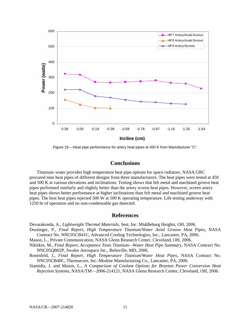
Figures 17, 18, and 19 show performance data curves for the heat pipes at 450 K. The heat pipes performed against gravity with a higher inclination at 450 K.
The heat pipes are currently undergoing life tests for 5 or more years to evaluate long term chemical compatibility between the titanium envelope, titanium wick material and water. Life testing is conducted at 500 K. Operation at the lower temperature, 360 K, is done periodically to check for the presence of non-condensable gasses (NCG) that may have been generated due to reactions between heat pipe materials or possible contaminants. The NCG, which occupy the end of the condenser, expand sufficiently at the lower operating temperature and pressure as to have their effect seen as a sharp heat pipe temperature change at the NCG boundary. Small quantities of non-condensable gas are sufficient to observe the phenomena. Any NCG will be sampled and analyzed for its constituents and determine the source of the reaction. Sources may be a reaction between the titanium and water, trace contaminants within the system or a leak. Life testing to date (1700 hr) has shown steady performance and no indication of non-condensable gas.
Gas Gap Calorimeter 110 cm
2 cm
3 cm 7 cm
5 cm
4 cm 6 cm
10 cm 15 cm
20 cm 30 cm
45 cm 60 cm 75 cm 108 cm
0 cm
CONDENSER
Figure 12.—Thermocouple locations on the condenser side of the heat pipe.

NASA/CR—2007-214820 8
0
100
200
300
400
500
600
0.38 0.00 -0.19 -0.38 -0.58 -0.78 -1.00 -1.21
Incline (cm)
Pow
er (W
atts
)
HP 1 Felt Metal Narrow Groove
HP 2 Felt Metal Groove/Screen
HP 3 Felt Metal Groove
Figure 13.—Performance data for felt metal axial groove heat pipes at 500 K from Manufacturer “A”.
0
100
200
300
400
500
600
0.38 0.00 -0.19 -0.38 -0.58Incline (cm)
Pow
er (W
atts
)
HP 4 19 Grooves
HP 5 23 Grooves
HP 6 17 Grooves
Figure 14.—Performance machined solid axial groove heat pipes at 500 K from Manufacturer “B”.

NASA/CR—2007-214820 9
0
100
200
300
400
500
600
0.38 0 -0.19 -0.38 -0.58 -0.78 -0.96 -1.15 -1.34
Incline (cm)
Pow
er (W
atts
)HP 7 Artery Threaded Evaporator
HP 8 Artery Threaded Evaporator
HP 9 Artery Screen Evaporator
Figure 15.—Performance screen axial artery heat pipes at 500 K from Manufacturer “C”.
0
100
200
300
400
500
600
0.38 0.00 -0.19 -0.38 -0.58 -0.78 -1.00 -1.21 -1.34Incline (cm)
Pow
er (W
atts
)
HP 1 Felt Metal
HP 2 Felt Metal
HP 3 Felt Metal
HP 4 Machine Groove
HP 5 Machine Groove
HP 6 Machine Groove
HP 7 Artery
HP 8 Artery
HP 9 Artery
Figure 16.—Comparison of all heat pipes at 500 K.

NASA/CR—2007-214820 10
0
100
200
300
400
500
600
0.38 0.00 -0.19 -0.38 -0.58 -0.78 -0.95 -1.14 -1.33 -1.52
Incline (cm)
Pow
er (w
atts
)HP 1 Felt Metal Narrow Groove
HP 2 Felt Metal Groove/Screen
HP 3 Felt Metal
Figure 17.—Heat pipe performance for felt metal groove heat pipes at 450 K from Manufacturer “A”.
0
100
200
300
400
500
600
0.38 0.00 -0.19 -0.38
Incline (cm)
Pow
er (w
atts
)
HP 4 19 Machine GrooveHP 5 23 Machine Groove
HP 6 17 Machine Groove
Figure 18.—Heat pipe performance for machined groove heat pipes at 450 K from Manufacturer “B”.
NASA/CR—2007-214820 11
0
100
200
300
400
500
600
0.38 0.00 -0.19 -0.38 -0.58 -0.78 -0.97 -1.16 -1.35 -1.54
Incline (cm)
Pow
er (w
atts
)
HP 7 Artery/Axial Groove
HP 8 Artery/Axial Groove
HP 9 Artery/Screen
Figure 19.—Heat pipe performance for artery heat pipes at 450 K from Manufacturer “C”.
Conclusions Titanium–water provides high temperature heat pipe options for space radiators. NASA GRC
procured nine heat pipes of different designs from three manufacturers. The heat pipes were tested at 450 and 500 K at various elevations and inclinations. Testing shows that felt metal and machined groove heat pipes performed similarly and slightly better than the artery screen heat pipes. However, screen artery heat pipes shows better performance at higher inclinations than felt metal and machined groove heat pipes. The best heat pipes rejected 500 W at 500 K operating temperature. Life testing underway with 1250 hr of operation and no non-condensable gas detected.
References Devarakonda, A., Lightweight Thermal Materials, Sest, Inc. Middleburg Heights, OH, 2006. Dussinger, P., Final Report, High Temperature Titanium/Water Axial Groove Heat Pipes, NASA
Contract No. NNC05CB41C, Advanced Cooling Technologies, Inc., Lancaster, PA, 2006. Mason, L., Private Communication, NASA Glenn Research Center, Cleveland, OH, 2006. Nikitkin, M., Final Report, Acceptance Tests Titanium—Water Heat Pipe Summary, NASA Contract No.
NNC05QB02P, Swales Aerospace Inc., Beltsville, MD, 2006. Rosenfeld, J., Final Report, High Temperature Titanium/Water Heat Pipes, NASA Contract No.
NNC05CB40C, Thermacore, Inc.-Modine Manufacturing Co., Lancaster, PA, 2006. Siamidis, J. and Mason, L., A Comparison of Coolant Options for Brayton Power Conversion Heat
Rejection Systems, NASA/TM—2006-214121, NASA Glenn Research Center, Cleveland, OH, 2006.

REPORT DOCUMENTATION PAGE Form Approved OMB No. 0704-0188
The public reporting burden for this collection of information is estimated to average 1 hour per response, including the time for reviewing instructions, searching existing data sources, gathering and maintaining the data needed, and completing and reviewing the collection of information. Send comments regarding this burden estimate or any other aspect of this collection of information, including suggestions for reducing this burden, to Department of Defense, Washington Headquarters Services, Directorate for Information Operations and Reports (0704-0188), 1215 Jefferson Davis Highway, Suite 1204, Arlington, VA 22202-4302. Respondents should be aware that notwithstanding any other provision of law, no person shall be subject to any penalty for failing to comply with a collection of information if it does not display a currently valid OMB control number. PLEASE DO NOT RETURN YOUR FORM TO THE ABOVE ADDRESS. 1. REPORT DATE (DD-MM-YYYY) 02-07-2007
2. REPORT TYPE Final Contractor Report
3. DATES COVERED (From - To)
4. TITLE AND SUBTITLE Thermal Performance of High Temperature Titanium—Water Heat Pipes by Multiple Heat Pipe Manufacturers
5a. CONTRACT NUMBER NNC05BA21B
5b. GRANT NUMBER
5c. PROGRAM ELEMENT NUMBER
6. AUTHOR(S) Sanzi, James, L.
5d. PROJECT NUMBER
5e. TASK NUMBER
5f. WORK UNIT NUMBER WBS 463169.04.03
7. PERFORMING ORGANIZATION NAME(S) AND ADDRESS(ES) Sest, Inc. 18000 Jefferson Park Road Suite 104 Middleburg Heights, OH 44130
8. PERFORMING ORGANIZATION REPORT NUMBER E-15978
9. SPONSORING/MONITORING AGENCY NAME(S) AND ADDRESS(ES) National Aeronautics and Space Administration Washington, DC 20546-0001
10. SPONSORING/MONITORS ACRONYM(S) NASA
11. SPONSORING/MONITORING REPORT NUMBER NASA/CR-2007-214820
12. DISTRIBUTION/AVAILABILITY STATEMENT Unclassified-Unlimited Subject Category: 20 Available electronically at http://gltrs.grc.nasa.gov This publication is available from the NASA Center for AeroSpace Information, 301-621-0390
13. SUPPLEMENTARY NOTES
14. ABSTRACT Titanium-water heat pipes are being investigated for use in heat rejection systems for lunar and Mars fission surface power systems. Heat pipes provide an efficient and reliable means to transfer heat to a radiator heat rejection system. NASA Glenn Research Center requisitioned nine titanium water heat pipes from three vendors. Each vendor supplied three heat pipes 1.25 cm diameter by 1.1 meter long with each vendor selecting a different wick design. Each of the three heat pipes is slightly different in construction. Additional specifications for the heat pipes included 500 K nominal operating temperature, light weight, and freeze tolerance. The heat pipes were performance tested gravity-aided, in the horizontal position and at elevations against gravity at 450 and 500 K. Performance of the three heat pipes is compared. The heat pipe data will be used to verify models of heat pipe radiators that will be used in future space exploration missions. 15. SUBJECT TERMS Titanium-water heat pipes; High temperature; Heat transfer
16. SECURITY CLASSIFICATION OF: 17. LIMITATION OF ABSTRACT
18. NUMBER OF PAGES
17
19a. NAME OF RESPONSIBLE PERSON James L. Sanzi
a. REPORT U
b. ABSTRACT U
c. THIS PAGE U
19b. TELEPHONE NUMBER (include area code) 216-433-5036
Standard Form 298 (Rev. 8-98)Prescribed by ANSI Std. Z39-18

