thermo-dynamics electric boilerthermodynamicsboiler.com/manuals/tde.pdf · thermo-dynamics electric...
TRANSCRIPT

Installation and Maintenance Manual
Thermo-Dynamics Boiler CompanyROUTE 61 • P.O. BOX 325 • SCHUYLKILL HAVEN, PA 17972
(570) 385-0731 FAX (570) 385-5304
THERMO-DYNAMICSElectric Boiler
A Compact, Versatile, Easy-to-UseHeat Source for Forced Hot Water Systems

The Thermo-Dynamics TDE Electric Boileris compact, clean, quite, and does not require
a storage facility or chimney allowing convenientinstallation near the point of use. The TDE electricboiler provides an energy efficient supply of warmand comfortable heat, and is built to Thermo-Dynamics quality standards – the highest in theheating industry.
This electric boiler is versatile and provides aneasy-to-use heat source for forced hot water systems in:
• new homes
• replacement systems in existing homes
• back-up units for solar heating systems
• supplemental heating systems for the heat pump.
CLEAN.The TDE heating system eliminates the need forfuel storage facilities and chimneys. There arenever any odors to permeate the home or combus-tion emissions to pollute our environment.
COMPACT.The TDE electric boiler is extremely compact andcan be easily wall-mounted almost anywhere in thehome to provide heat for areas that are isolatedfrom the main heat supply. These areas includegarages, apartments, and utility rooms to name afew.
QUIET.Quiet operation is maintained because elements areenergized in steps, thus preventing power surge andstart-up vibration. Quality electrical componentry,circulator and cabinet design also contribute to thewhisper-quiet operation of the TDE electric boiler.
ENERGY EFFICIENT.With Thermo-Dynamic’s unique “flow control”system, the TDE electric boiler delivers a steadyflow of healthful heat using a minimal amount ofelectricity. Low watt density heating elements, lowvoltage thermostat and thorough insulation forminimum heat loss are just a few design featuresbuilt in to deliver more comfort for every energydollar.
SMALL BOILER.BIG IDEAS.When your projects call for the efficiency of hotwater heat and the convenience of electricity,choose the TDE electric boiler. The TDE is smallenough to install almost anywhere (remember, allyou need is a wall), yet powerful to handle big hotwater heating jobs.
A Word About SupplementalHeat for the Heat Pump
If you live in the great northeast, or in a regionof the country where temperatures regularlyfall below 40°F in the winter, the heat pump willrun almost constantly to heat the home. Whenthe temperatures fall below 32°F, most heatpumps literally shut down and the resistance heatcomes on to provide back-up.
To extend the life of the very expensive heatpump unit, the electric boiler provides supple-mental heat allowing the heat pump to “rest.”
When heat is called for when the temperaturedrops below 32°F, the air in the heat pump sys-tem is below body temperature and thereforefeels cool. The electric boiler can provide a heatsource that is warm and comfortable to the touch.
Thermo-Dynamics TDE Electric Boiler

Designed forReliable HomeHeating Comfort
A Summary of Practical Applications
• Solar Heating Systems. Every active solar heatingsystem needs a reliable back-up heating unit that canperform through long periods of adverse weather.The TDE is UL listed as a central heating boiler, thus providing the power needed for total solar security.
• Recreational Pools. Because the TDE heats waterfast and efficiently, it is an ideal way to warm swimming pool water. Ideal for home, hotel, club and spa pools, and popular with the hot tubs, too. Itspowerful circulator maintains steady flow to keepwater at uniform temperature.
• Therapeutic Pools. Sports and institutional facilities need a precisely regulated hot water supplyfor their hydrotherapy facilities. Of course, the TDEis the safe choice, offering a high limit switch featurethat instantly de-energizes heating elements at a settemperature while the circulator continues operation.
• Condominiums, Co-ops, Apartments. When eachliving unit needs individual hot water heat, the TDE isthe cost-efficient answer. It features staged start-upfor quiet operation; can be easily piped into existinghydronic systems; is great for new construction; and anecessity for conversion projects.
A Summary of Product Features• Five models: 10 kw to 30 kw.• One-piece steel boiler shell.• Easily accessible controls.• Low voltage thermostat.• Heats single or multi-zone systems.• Heat process water used in a manufacturing process.
• Boiler Cabinet easily removes before or after piping unit to system.
• UL Listed as central heating boiler.• Circulator piped and wired at factory.• 10 Year, plus 10 years pro-rated at 5% per year, limited warranty on boiler shell; full year limited warranty on all other components.
• One-piece steel boiler shell, ASME-constructed.• Built-in dip tube air elimination system.• Low voltage thermostat.• Uniform water temperature.• Factory tested.• Low voltage fuse protected control circuit.
A Summary of Product Benefits
The Thermo-Dynamic TDE electric boiler features low watt density heating elements installed through thesides of the boiler with ample access for service. The elements are energized in steps to prevent power
surge, prolonging heater element life and assuring quiet operation.
Standard controls are factory-wired on the control panel. All controls are easily accessible through the removable cover.
Every TDE boiler is insulated with fiberglass insulation for minimum heat loss and housed in a rugged steelcabinet finished in azure blue powder coat for extra durability.
Clean, compact, quiet, energy efficient, versatile, affordable, and backed by Thermo-Dynamics.

Thermo-Dynamics
Energy efficiency is an important consideration when buying any heating system. But there are other fac-tors you must consider too. Like manufacturer experience, reputation and service. The simple fact is, any
heating system is only as good as the company behind it.
Only the finest materials and craftsmanship is used to manufacture our products.
OperationOn call for heat the circulator comes on immediately, and the elements are energized in steps — two elementsper step spaced at approximately 60 second intervals. When the thermostat is satisfied, all elements and circu-lator are de-energized at once. A high limit condition will instantly de-energize all elements and the circulatorwill continue to run.
Ratings
ELECTRICAL CHARACTERISTICS — 120/240 VOLTS A.C. 3 WIRE SINGLE PHASE 60 HZ*Net ratings are based on installed radiation of sufficient quantity to serve the requirements of the building and nothing need be added for normal piping and pick up. Net rating is based on a piping and pick up allowance of 13%.
Dimensions EquipmentSteel boiler, jacket, insulation, controls andcirculator
Factory Installed – ASME relief valve,temperature and pressure gauge, elements,circulator, drain cock, completely wired.
Included but not installed Air vent, thermostat.
Boiler Size
TDE-10TDE-15TDE-20TDE-25TDE-30
KW Rating
1015202530
Input
34,00051,00068,00085,000102,000
Gross Output
34,00051,00068,00085,000102,000
*Net Output
30,00044,00059,00074,00089,000
14343434343
2–21424242
3–––2142
Total
436485106127
No. of 5KWHeaterElements
23456
Wattsat
240V
10,00015,00020,00025,00030,000
Approx.ShippingWgt. Lbs.
120125125141150
BTU/Hour AmpsCircuit

1
CAUTION: READ ME FIRST
Check the unit for shipping damage. If there is any evidence of damage,including damage to the exterior jacket, you should contact your freightcompany immediately and file a claim. Do not install the boiler.
Proper selection of the right size TDE, or any heating device, requires anaccurate heat balance performed by a qualified heating professional.Consult the supplier of the indirect hot water heater or Thermo-Dynamicsfor detailed instructions related to indirect hot water heater applications.Follow the indirect hot water heater installation and piping instructions toensure proper performance.
These instructions include options for installation, including system com-ponents. Components are not provided, unless specifically noted other-wise. Suggested installation schemes are for the brand names specified. Ifanother brand is used, see the manufacturer’s instructions for installation.
Installation of the Thermo-Dynamics TDE electric boiler requires an expe-rienced and trained service person. The TDE is similar to an oil or gas firedboiler in many ways. The differences are important. Follow the installationinstructions carefully to avoid problems. Contact Thermo-Dynamics if youhave any questions or concerns.
Wiring, piping and construction must meet all local, state and federalcodes that may apply. In the event that no local electrical codes apply, theNational Electrical Code should be followed.
See the outline and dimension drawing on page 6 for location of all elec-trical and hydronic connections.
Before you start. You will need the following:
Four 3/16" lag screws or toggle bolts for mounting.A low voltage, remote mounting thermostat.Expansion tank: Check manufacturer’s instructions for sizing criteria.Isolation valves, piping and zone devices as described in the installation diagrams.
2
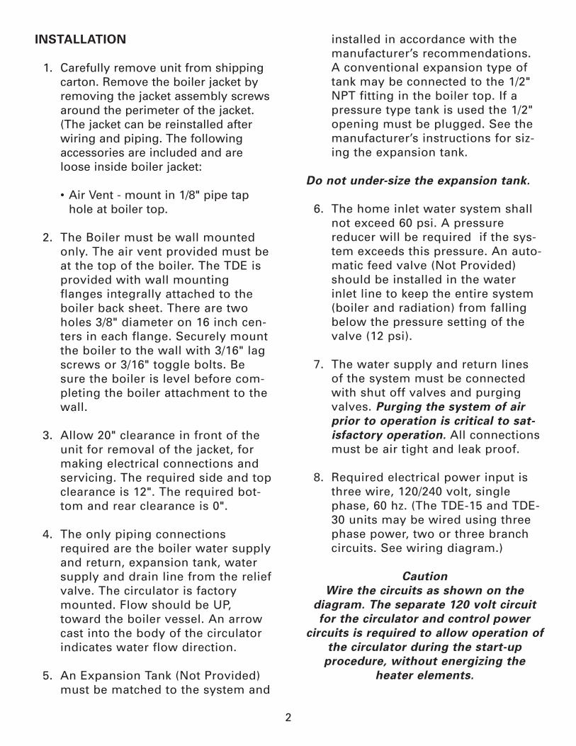
INSTALLATION
1. Carefully remove unit from shipping carton. Remove the boiler jacket byremoving the jacket assembly screwsaround the perimeter of the jacket.(The jacket can be reinstalled afterwiring and piping. The followingaccessories are included and areloose inside boiler jacket:
• Air Vent - mount in 1/8" pipe taphole at boiler top.
2. The Boiler must be wall mountedonly. The air vent provided must beat the top of the boiler. The TDE isprovided with wall mountingflanges integrally attached to theboiler back sheet. There are twoholes 3/8" diameter on 16 inch cen-ters in each flange. Securely mountthe boiler to the wall with 3/16" lagscrews or 3/16" toggle bolts. Besure the boiler is level before com-pleting the boiler attachment to thewall.
3. Allow 20" clearance in front of theunit for removal of the jacket, formaking electrical connections andservicing. The required side and topclearance is 12". The required bot-tom and rear clearance is 0".
4. The only piping connections required are the boiler water supplyand return, expansion tank, watersupply and drain line from the reliefvalve. The circulator is factorymounted. Flow should be UP,toward the boiler vessel. An arrowcast into the body of the circulatorindicates water flow direction.
5. An Expansion Tank (Not Provided)must be matched to the system and
installed in accordance with themanufacturer’s recommendations.A conventional expansion type oftank may be connected to the 1/2"NPT fitting in the boiler top. If apressure type tank is used the 1/2"opening must be plugged. See themanufacturer’s instructions for siz-ing the expansion tank.
Do not under-size the expansion tank.
6. The home inlet water system shall not exceed 60 psi. A pressurereducer will be required if the sys-tem exceeds this pressure. An auto-matic feed valve (Not Provided)should be installed in the waterinlet line to keep the entire system(boiler and radiation) from fallingbelow the pressure setting of thevalve (12 psi).
7. The water supply and return lines of the system must be connectedwith shut off valves and purgingvalves. Purging the system of airprior to operation is critical to sat-isfactory operation. All connectionsmust be air tight and leak proof.
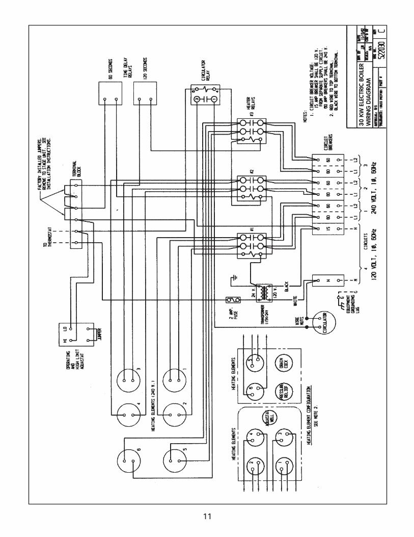
8. Required electrical power input is three wire, 120/240 volt, singlephase, 60 hz. (The TDE-15 and TDE-30 units may be wired using threephase power, two or three branchcircuits. See wiring diagram.)
CautionWire the circuits as shown on the
diagram. The separate 120 volt circuitfor the circulator and control power
circuits is required to allow operation ofthe circulator during the start-up procedure, without energizing the
heater elements.

3
9. Circuit breaker size is 60 amps per heater circuit and 15 amps for thecirculator pump and control circuit.The 24 volt control circuit is pro-tected with a 2 amp ferrule fuse.
10. An opening is provided in the cabi-net lower right hand corner of theboiler for input wiring. All wiringmust be in accordance with localelectric code, or the NationalElectric Code in the absence of alocal code.
Warning: DISCONNECT ALLWIRING AT THE MAIN SWITCH
BEFORE WIRING UNIT
11. Connect power to terminals marked L1 and L2 and the neutral leg of thethree wire service to the terminalmarked N (neutral).
12. Connect a ground wire to the case ground connection and connect theground wire to a ground that meetslocal electrical codes. Impropergrounds may result in unsafe con-ditions and interfere with otherelectronic devices.
13. Replace boiler jacket and re-install assembly screws. Remove the doorholding screw to allow the door tobe opened.
Re-install the door holding screw whenthe system is operating to avoid acci-dental or unintentional opening of thedoor.
14. Install the thermostat (not included) in accordance with the instructions provided by the manufacturer.
Caution: The Thermostat, ground wireand power wires are the only connec-tions that should be made to the TDE.Do not supply power to any other sys-tem components from the TDE.
OPERATION
Caution: Follow the start-up procedurecarefully and completely. Failure to fol-low the start-up procedure may causedamage to components including theheater elements.
START-UP
1. Verify that the supply breaker at the main circuit breaker panel to theTDE and all of the TDE electricalbreakers are in the off position.
NEVER PUT ELECTRICAL POWER TOBOILER UNLESS BOILER AND
HYDRONIC SYSTEM ARE FULL OF WATER.
2. Fill the hydronic system and the boiler. Purge all air from the systemat the purge valve. If it is a multi-zone system, air purge each system.
3. Turn the supply breaker in the Main Circuit panel for 120 volt power tothe TDE to on. Turn the 15 ampbreaker in the TDE to on. DO NOTENERGIZE THE HEATER CIRCUITS.The 15 amp breaker provides powerto the circulator and the controls.Turn the thermostat up until it turnsthe circulator on. If multiple zonecirculators are installed, turn thezone circulators on. Continue tovent the system with the circulatorsrunning, until all air is purged.
4. The pressure gauge should read 12psi if an automatic feed valve is

4
used. If equipped with manual feed,close the system water supplyvalve when a pressure reading of12 psi is obtained. The purge valvemay have to be bled to reducepressure to 12 psi.
Check the system for leaks by shuttingthe water supply valve and observingthe pressure gauge. Any decrease insystem pressure indicates a leak thatmust be repaired prior to operation.
5. Set the thermostat at the lowest setting. Turn the supply breaker forthe TDE at the main circuit breakerpanel to on. Turn all TDE breakersto on.
6. Raise the thermostat to above room temperature. The unit should oper-ate. The pump and heater elementrelays will cycle on and off accord-ing to demand of the thermostatand timing sequence. See theSequence of Operation section inthis manual for time delay descrip-tion.
7. The pressure of the system will risewhen heated. The normal pressuregauge reading should be between20 and 22 psi. If pressure risesabove 22 psi, additional expansiontank capacity may be necessary.See the manufacturer’s manual forinformation on sizing the expansiontank.
Note:
The pressure relief valve is a safetydevice set to open at 30 psi.
8. Set the heat anticipator in the ther-mostat in accordance with the man-ufacturers directions, if soequipped.
When installation is complete andthe system is operating satisfac-torily, close the cabinet door andre-install the door holding screwto prevent accidental or uninten-tional opening of the door.
SEQUENCE OF OPERATION
The thermostat closes on a call for heatand energizes the circulator relay andthe first heater relay which pulls in thecirculator and two heating elements.The remaining elements are energizedon at one minute intervals (two ele-ments at one time). When the thermo-stat is satisfied, all the elements de-energize at once and the circulatorstops.
Operating temperatures on the temperature gauge of the TDE may be 110 - 140° F, or lower. This is normal for the TDE.
This unit is furnished with a dual hotwater control aquastat with a High LimitSafety Setting (labeled “Hi”) and anOperating Control Limit Setting (labeled“Lo”). The High Limit Safety is factoryset at 200°F. The Operating ControlLimit is set at 170°. If the boiler waterreaches 170° the Operating ControlLimit will open the heater relay circuitcausing heater elements to de-energize,even though the thermostat may becalling for heat. The circulator will con-tinue to run, as long as the thermostatis calling for heat. When boiler watertemperature drops to 160° theOperating Control Limit will close andbring the heating elements back on,provided that the thermostat is callingfor heat.

5
If the water temperature reached 200°,due to a failure of the Operating ControlLimit, for example, the High Limit safetywill shut off all elements at once.
The High Limit Safety is set at 200° Do not attempt to change the High
Limit setting. Do not set the OperatingControl Limit above 180°. Remember,this is not a low temperature set pointlike on an oil or gas fired boiler. Thereis no low set point and, if there is a callfor heat, the circulator will run and theelements will be energized as long asthe thermostat calls for heat and theOperating Control Limit and High
Safety limit are not reached.
Refer to the instruction sheet for thecontrol when making adjustments.
MAINTENANCE
A trained and experienced service per-son should check the system prior toeach heating season. The supply break-er to the electric boiler should be offprior to performing any service.
If a component is changed in the sys-tem, follow the start-up procedure inthis manual prior to operating the unit.
Check for leaks after every mainte-nance, once per year and if there is anyvisual evidence of a leak. To check forleaks, shut the water supply valve andobserve the pressure gauge. Any loss ofpressure indicates a leak in the systemthat must be repaired.
Frequent heater element failures orshort heater element life is an indicationthat there is air in the system. Followthe start-up procedure to make surethat all air is eliminated from the sys-tem and verify that the system is leak-
free to prevent introduction of air dur-ing operation.
Staging
The TDE-15, 20, 25 and 30 can be“staged” using a second thermostat ora dual thermostat. Staging may be avaluable feature if the user’s electric billis based on peak demand. Staging pre-vents the timed elements from energiz-ing unless the temperature set point ofa second or third thermostat is reached.A careful heat balance is required to setthe TDE for effective staged operation.
The staging terminals shown in thewiring diagrams have a factory installedjumper when delivered. When the ther-mostat closes on a call for heat, the firsttwo heater elements are energizedimmediately. The remaining elementsare energized, two at a time at oneminute intervals. To stage the TDE,remove the factory installed jumper andinstall a thermostat or outdoor stat (Notprovided) wired to the same terminalswhere the jumper was removed. Thethermostat may be located outdoors, orin a zoned space and set or selected sothat if the temperature is above thethermostat set point, heater elementsthat are time delayed will not turn on. Ifthe outside temperature or a separatezone temperature is below the secondthermostat set point, the time delayedheater elements will be energized afterthe appropriate time delay. The TDE-25and 30 have two staging terminal sets.The second factory installed jumper canbe used so that the first two heaters areenergized by a call for heat from theinterior thermostat and the remainingheater elements are energized only ifthe second thermostat set points arereached. Both sets of staging terminalscan be connected to thermostats to

6
allow two of the heater elements tocome on after time delay if one setpoint is reached and the remainingheaters will be energized if the other setpoint is reached.
When using outside temperature tostage, start by setting the first stagedthermostat at 40°F. Set a second ther-mostat at 20°F if a second stage is used.If required, adjust the thermostats tomaintain desired level of comfort.
3/4" NPT FOR RELIEF VALVE(FACTORY INSALLED)
3/4" DRAIN VALVE(FACTORY INSALLED)
1-1/4" NPT FORSYSTEM SUPPLY
PRESSURE &TEMPERATURE GAUGE
THERMOSTATWIRING ACCESS
NAMEPLATE /RATING PLATE
3/8" DIA.MOUNTING HOLES (4)
ELECTRICALWIRING ACCESS
1-1/4" NPT FORWATER SUPPLY/COLD WATER RETURN
1/8" NPT FOR AIR VENT(FIELD INSTALLED)
1/2" NPT FOR FIELDCONNECTION TO CONVENTIONALEXPANSION TANK (NOTE 1)
11 3/4
23/4
4 7/8
2
215/8 TYP.
19 5/8
20 1/4
4 7/8
2 3/8
9 1/8 4 3/4
3
11 3/4
26 3/8
7
16
NOTES:1. SEE INSTRUCTIONS FORDETAILED INFORMATION.
2. ALL DIMENSIONS AREFOR REFERENCE ONLY.
11
Thermo-DynamicsDWG NO. TDE-011

7

8

9

10
11

12

13
PIPING DIAGRAM, DIAPHRAGM TYPE EXPANSION TANK
PIPING DIAGRAM, CONVENTIONAL EXPANSION TANK
TDE
TDE
14

15
Thermo-Dynamics Electric Boiler
Power Supply Wire Sizes
Split Power Supply
Wire Sizes AWG Copper
Model 10 15 20 25 30
N 14 14 14 14 14
Circuit 1 L1 6 6 6 6 6
L2 6 6 6 6 6
L1 8 6 6 6Circuit 2
L2 8 6 6 6
L1 8 6Circuit 3
L2 8 6
Equipment GRD. 6 6 6 6 6
Model 10 15 20 25 30
Wire Size 6 4 2 1 00
Single Power Supply

TDE ELECTRIC BOILER WARRANTY
A. Full Three Year Warranty. Thermo-Dynamics warrants the TDE boiler units are free fromdefects in material and workmanship for 3 years from date of installation. If any parts are foundto be defective in manufacture, Thermo-Dynamics will repair or replace them at Thermo-Dynamics’ option.
B. Limited Lifetime Warranty: Thermo-Dynamics warrants that the steel boiler of it’s TDEboiler is free from defects in material and workmanship. Any boiler found to be defective willbe repaired or replaced at Thermo-Dynamics’ option.
This warranty does not cover:1. Boilers located out of doors.2. Components of the heating system not supplied by Thermo-Dynamics.3. Workmanship of the installer. This warranty does not assume any liability of any nature for unsatisfactory performance caused by improper installation.
4. Failures due to shipping damage. Any evidence of shipping damage must be reported to the shipping company immediately and a claim filed. Do not install the boiler.
5. Improper adjustments, control settings, care, maintenance or failure to follow installation instructions provided with the boiler.
6. Defects resulting from freezing, excessive pressure, temperature or leaks at water connec-tions or any similar cause.
7. Any installation that has been modified, neglected, altered, tampered with, vandalized, misused subjected to accident, fire, flood or other casualty.
8. Installations for which a heat balance provided by an experienced heating professional indicates that the boiler is inadequate for the application.
This warranty does not extend to anyone except for the first purchaser at retail, and only whenthe boiler is in the original installation site, which must be within the continental limits of theUnited Sates.
Implied warranties of fitness for a particular purpose and merchantability shall be limited to theduration of the express warranty. Thermo-Dynamics expressly disclaims and excludes any lia-bility for consequential or incidental damages for breach of any express or implied warranty,except as otherwise provided by state law.
For prompt service, notify the installer, who in turn will notify the distributor who supplied theboiler. Alleged defective parts must be returned in accordance with the Thermo-Dynamics pro-cedure currently in force. Thermo-Dynamics will provide the new parts to the installing dealeror distributor.
This warranty gives you specified legal rights. You may have other rights that vary from state tostate.
MET-6709