thermo multichannel lc · weee directive 2012/19/eu thermo fisher scientific is registered with b2b...
TRANSCRIPT

Thermo
Multichannel LCMaintenance Guide
60500-97005 Revision A June 2017

© 2017 Thermo Fisher Scientific Inc. All rights reserved.
Accucore, Aria, Foundation, LCquan, Transcend, and TraceFinder are trademarks, and Thermo Scientific, Xcalibur, Accela, TriPlus, and UltiMate are registered trademarks of Thermo Fisher Scientific Inc. in the United States.
The following are registered trademarks in the United States and other countries: Windows and Microsoft are registered trademarks of Microsoft Corporation. Agilent is a registered trademark of Agilent Technologies, Inc.
The following are registered trademarks in the United States and possibly other countries: Fluorinert is a trademark of 3M Company. Fomblin is a registered trademark of Solvay Specialty Polymers Italy S.P.A. Freon and Teflon are registered trademarks of The Chemours Company. Parafilm is a registered trademark of the Bemis Company. Shimadzu is a registered trademark of Shimadzu Corporation.
PAL is a registered trademark of CTC Analytics AG in Switzerland.
All other trademarks are the property of Thermo Fisher Scientific Inc. and its subsidiaries.
Thermo Fisher Scientific Inc. provides this document to its customers with a product purchase to use in the product operation. This document is copyright protected and any reproduction of the whole or any part of this document is strictly prohibited, except with the written authorization of Thermo Fisher Scientific Inc.
The contents of this document are subject to change without notice. All technical information in this document is for reference purposes only. System configurations and specifications in this document supersede all previous information received by the purchaser. This document is not part of any sales contract between Thermo Fisher Scientific Inc. and a purchaser. This document shall in no way govern or modify any Terms and Conditions of Sale, which Terms and Conditions of Sale shall govern all conflicting information between the two documents.
Release history: Revision A, June 2017
For Research Use Only. Not for use in diagnostic procedures.

Regulatory Compliance
Thermo Fisher Scientific performs complete testing and evaluation of its products to ensure full compliance with applicable domestic and international regulations. When the system is delivered to you, it meets all pertinent electromagnetic compatibility (EMC) and safety standards as described in the next section or sections by product name.
Changes that you make to your system may void compliance with one or more of these EMC and safety standards. Changes to your system include replacing a part or adding components, options, or peripherals not specifically authorized and qualified by Thermo Fisher Scientific. To ensure continued compliance with EMC and safety standards, replacement parts and additional components, options, and peripherals must be ordered from Thermo Fisher Scientific or one of its authorized representatives.
Notice of Proper Use of Thermo Scientific Instruments
In compliance with international regulations: The instruments described herein must be used in the manner specified by Thermo Fisher Scientific to ensure protections provided by the instrument are not impaired. Deviations from specified instructions on the proper use of these instruments include changes to the system and part replacement. Accordingly, order replacement parts from Thermo Fisher Scientific or one of its authorized representatives.

WEEE Directive2012/19/EU
Thermo Fisher Scientific is registered with B2B Compliance (B2Bcompliance.org.uk) in the UK and with the European Recycling Platform (ERP-recycling.org) in all other countries of the European Union and in Norway.
If this product is located in Europe and you want to participate in the Thermo Fisher Scientific Business-to-Business (B2B) Recycling Program, send an email request to [email protected] with the following information:
• WEEE product class
• Name of the manufacturer or distributor (where you purchased the product)
• Number of product pieces, and the estimated total weight and volume
• Pick-up address and contact person (include contact information)
• Appropriate pick-up time
• Declaration of decontamination, stating that all hazardous fluids or material have been removed from the product
For additional information about the Restriction on Hazardous Substances (RoHS) Directive for the European Union, search for RoHS on the Thermo Fisher Scientific European language websites.
IMPORTANT This recycling program is not for biological hazard products or for products that have been medically contaminated. You must treat these types of products as biohazard waste and dispose of them in accordance with your local regulations.


Thermo Scientific Multichannel LC Maintenance Guide vii
C
Preface . . . . . . . . . . . . . . . . . . . . . . . . . . . . . . . . . . . . . . . . . . . . . . . . . . . . . . . . . . . . . . ixDocument Overview . . . . . . . . . . . . . . . . . . . . . . . . . . . . . . . . . . . . . . . . . . . . . .ixSystem Documentation . . . . . . . . . . . . . . . . . . . . . . . . . . . . . . . . . . . . . . . . . . . .xiSafety and Special Notices . . . . . . . . . . . . . . . . . . . . . . . . . . . . . . . . . . . . . . . . .xiiiSafety Information. . . . . . . . . . . . . . . . . . . . . . . . . . . . . . . . . . . . . . . . . . . . . . .xiiiEnvironmental Conditions . . . . . . . . . . . . . . . . . . . . . . . . . . . . . . . . . . . . . . . .xviGood Laboratory Practices . . . . . . . . . . . . . . . . . . . . . . . . . . . . . . . . . . . . . . . .xvi
Keeping Good Records . . . . . . . . . . . . . . . . . . . . . . . . . . . . . . . . . . . . . . . . .xviChemical Toxicity . . . . . . . . . . . . . . . . . . . . . . . . . . . . . . . . . . . . . . . . . . . . .xviSolvent Requirements . . . . . . . . . . . . . . . . . . . . . . . . . . . . . . . . . . . . . . . . . xviiSolvent Disposal . . . . . . . . . . . . . . . . . . . . . . . . . . . . . . . . . . . . . . . . . . . . . xviiHigh-Pressure Systems and Leaks . . . . . . . . . . . . . . . . . . . . . . . . . . . . . . . . xvii
Contacting Us . . . . . . . . . . . . . . . . . . . . . . . . . . . . . . . . . . . . . . . . . . . . . . . . .xviii
Chapter 1 Maintenance Schedule . . . . . . . . . . . . . . . . . . . . . . . . . . . . . . . . . . . . . . . . . . . . . . . . .1
Chapter 2 Preparing Solutions . . . . . . . . . . . . . . . . . . . . . . . . . . . . . . . . . . . . . . . . . . . . . . . . . . . .3Preparing the TurboFlow Column Wash Solvent . . . . . . . . . . . . . . . . . . . . . . . . 3Preparing the Mobile Phase Solvents . . . . . . . . . . . . . . . . . . . . . . . . . . . . . . . . . . 4Preparing the Rear Seal Wash Solution . . . . . . . . . . . . . . . . . . . . . . . . . . . . . . . . 4Preparing the Autosampler Wash Solutions . . . . . . . . . . . . . . . . . . . . . . . . . . . . . 5
Chapter 3 Aria MX Software-based Maintenance . . . . . . . . . . . . . . . . . . . . . . . . . . . . . . . . . . .7Accessing the Direct Control Window . . . . . . . . . . . . . . . . . . . . . . . . . . . . . . . . 7Tracking the Number of Injections . . . . . . . . . . . . . . . . . . . . . . . . . . . . . . . . . . . 9Managing the LC Pumps. . . . . . . . . . . . . . . . . . . . . . . . . . . . . . . . . . . . . . . . . . 12
Priming the LC Pumps for Transcend Systems . . . . . . . . . . . . . . . . . . . . . . . 12Priming the LC Pumps for Prelude SPLC . . . . . . . . . . . . . . . . . . . . . . . . . . . 14Recording Pump Pressures. . . . . . . . . . . . . . . . . . . . . . . . . . . . . . . . . . . . . . . 17Purging Thermo Scientific UltiMate Pumps (Transcend II systems) . . . . . . . 18
Seal Wash Pump Standby (Power Save Mode) for Transcend II Systems. . . . . . 21Configuring Seal Wash Standby . . . . . . . . . . . . . . . . . . . . . . . . . . . . . . . . . . 21Seal Wash Standby Options . . . . . . . . . . . . . . . . . . . . . . . . . . . . . . . . . . . . . 22
Contents

Contents
viii Multichannel LC Maintenance Guide Thermo Scientific
Chapter 4 Autosampler Maintenance . . . . . . . . . . . . . . . . . . . . . . . . . . . . . . . . . . . . . . . . . . . . .25Supported Autosampler Models . . . . . . . . . . . . . . . . . . . . . . . . . . . . . . . . . . . . 25Verifying Wash Solutions . . . . . . . . . . . . . . . . . . . . . . . . . . . . . . . . . . . . . . . . . 26
Verifying Wash Solutions for the Accela Open Fast Wash Stations . . . . . . . . 26Verifying Wash Solutions for the TriPlus . . . . . . . . . . . . . . . . . . . . . . . . . . . 27
Syringe and Needle Maintenance . . . . . . . . . . . . . . . . . . . . . . . . . . . . . . . . . . . 28Accela Open Syringe and Needle Replacement . . . . . . . . . . . . . . . . . . . . . . . 28TriPlus Syringe and Needle Replacement . . . . . . . . . . . . . . . . . . . . . . . . . . . 44
Downloading Autosampler Objects to Aria MX (Accela Open). . . . . . . . . . . . . 45Priming the Dynamic Load Wash (DLW) Wash System. . . . . . . . . . . . . . . . . . 46Priming the TriPlus LCMS-P Tool Wash Pumps . . . . . . . . . . . . . . . . . . . . . . . 46
Chapter 5 General LC System Maintenance. . . . . . . . . . . . . . . . . . . . . . . . . . . . . . . . . . . . . . . .49Replacing the Rotor Seals . . . . . . . . . . . . . . . . . . . . . . . . . . . . . . . . . . . . . . . . . 49Replacing the Valve Needle Seal . . . . . . . . . . . . . . . . . . . . . . . . . . . . . . . . . . . . 51Replacing Columns . . . . . . . . . . . . . . . . . . . . . . . . . . . . . . . . . . . . . . . . . . . . . . 52
Replacing the TurboFlow Column . . . . . . . . . . . . . . . . . . . . . . . . . . . . . . . . 53Replacing the Analytical Column . . . . . . . . . . . . . . . . . . . . . . . . . . . . . . . . . 54
Cleaning System Components. . . . . . . . . . . . . . . . . . . . . . . . . . . . . . . . . . . . . . 55Cleaning the Solvent Lines, Pumps, and Valves . . . . . . . . . . . . . . . . . . . . . . . 56Cleaning the Solvent Lines and Pumps . . . . . . . . . . . . . . . . . . . . . . . . . . . . . 57
Computer (Data System) Maintenance . . . . . . . . . . . . . . . . . . . . . . . . . . . . . . . 58Periodic Computer System Updates . . . . . . . . . . . . . . . . . . . . . . . . . . . . . . . 58Suspending Computer Sleep Mode When Running Aria MX . . . . . . . . . . . . 58
Appendix A Replaceable Parts and Consumables . . . . . . . . . . . . . . . . . . . . . . . . . . . . . . . . . . . .59General Consumables . . . . . . . . . . . . . . . . . . . . . . . . . . . . . . . . . . . . . . . . . . . . 59Aria Spare Parts . . . . . . . . . . . . . . . . . . . . . . . . . . . . . . . . . . . . . . . . . . . . . . . . . 60Transcend II, Transcend UHPLC Spare Parts . . . . . . . . . . . . . . . . . . . . . . . . . . 61Prelude SPLC Spare Parts . . . . . . . . . . . . . . . . . . . . . . . . . . . . . . . . . . . . . . . . . 61TriPlus RSI Autosampler Spare Parts. . . . . . . . . . . . . . . . . . . . . . . . . . . . . . . . . 62Chemicals List . . . . . . . . . . . . . . . . . . . . . . . . . . . . . . . . . . . . . . . . . . . . . . . . . . 62
Thermo Scientific Multichannel LC Maintenance Guide ix
P
Preface
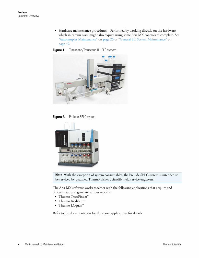
The Thermo Scientific™ Transcend II, Transcend™ (see Figure 1 on page x) and Prelude SPLC™ (see Figure 2 on page x) are LC systems that have been optimized to run TurboFlow or laminar flow methods on multiple channels. They use Aria MX software, interfaced with your mass spectrometer applications, to control the LC system pumps, valves, and autosampler.
Contents
• Document Overview
• System Documentation
• Safety and Special Notices
• Safety Information
• Environmental Conditions
• Good Laboratory Practices
• Contacting Us
Document OverviewThis guide provides information on the various Aria MX-based software and hardware maintenance procedures necessary to keep your Transcend II, Transcend, or Prelude SPLC system operating at peak performance. For details about operating your system, refer to its user guide. For details on how to create methods and run samples with your mass spectrometer (MS), refer to the Aria MX User Guide or the Prelude SPLC System User Guide.
There are two general categories of procedures described in this guide:
• Software-based maintenance procedures—Performed directly through the Aria MX software. Some of these procedures might require access to the hardware for certain operations. See “Aria MX Software-based Maintenance” on page 7.
PrefaceDocument Overview
x Multichannel LC Maintenance Guide Thermo Scientific
• Hardware maintenance procedures—Performed by working directly on the hardware, which in certain cases might also require using some Aria MX controls to complete. See “Autosampler Maintenance” on page 25 or “General LC System Maintenance” on page 49.
Figure 1. Transcend/Transcend II HPLC system
Figure 2. Prelude SPLC system
The Aria MX software works together with the following applications that acquire and process data, and generate various reports:
• Thermo TraceFinder™• Thermo Xcalibur™• Thermo LCquan™
Refer to the documentation for the above applications for details.
Note With the exception of system consumables, the Prelude SPLC system is intended to be serviced by qualified Thermo Fisher Scientific field service engineers.

PrefaceSystem Documentation
Thermo Scientific Multichannel LC Maintenance Guide xi
System DocumentationYour LC system ships with the Aria MX DVD, which includes technical documentation for the applications that run in your environment.
In addition to this guide, Thermo Fisher Scientific provides the following documentation for the LC system:
• Aria MX User Guide as a PDF file and Help (from the Aria MX Help menu)
• Prelude SPLC System User Guide as a PDF file.
• TraceFinder manuals as PDF files (when TraceFinder software is installed on your data system computer)
• TraceFinder Help (from the TraceFinder application window)
• Xcalibur manuals as PDF files (when Xcalibur software is installed on your data system computer)
• Xcalibur Help (from the Xcalibur application window)
• LC pump user documentation
• Autosampler user documentation
To view the Aria MX User Guide
Choose Start > All Programs > Thermo Instruments > Aria MX.
To view TraceFinder manuals if available on your system
Choose Start > All Programs > Thermo TraceFinder > Manuals.
To view TraceFinder Help if available on your system
Click the Help icon in the upper right corner of any TraceFinder window.
To view the Xcalibur user documentation
1. Choose Start > All Programs > Thermo Xcalibur > Manuals > Xcalibur.
To view the Xcalibur Help
Choose a command from the Help menu or click ? in the upper left corner of any Xcalibur window.

PrefaceSystem Documentation
xii Multichannel LC Maintenance Guide Thermo Scientific
To view instructions on navigating the Xcalibur Help
1. Click the expand icon (+) beside the Welcome to Xcalibur Help book to view the topics.
2. Select Using This Help.
Navigation instructions appear on the topic page.
To view the Aria MX Help
1. Open the Aria MX Direct Control window.
2. Choose Help > Help, or press F1.
To view other manuals that might be available on your computer
Choose Start > All Programs > Thermo product name > Manuals.
Table 1 describes the Thermo Fisher Scientific product manuals provided on the Aria MX DVD.Table 1. Aria MX DVD manual list
Manual name Description
Aria MX User Guide Describes procedures for LC systems—like Transcend II, Transcend, and Prelude SPLC—that use the Aria MX software.
Prelude SPLC System User Guide Describes the recommended procedures for operating and maintaining a Prelude SPLC system.
PrefaceSafety and Special Notices
Thermo Scientific Multichannel LC Maintenance Guide xiii
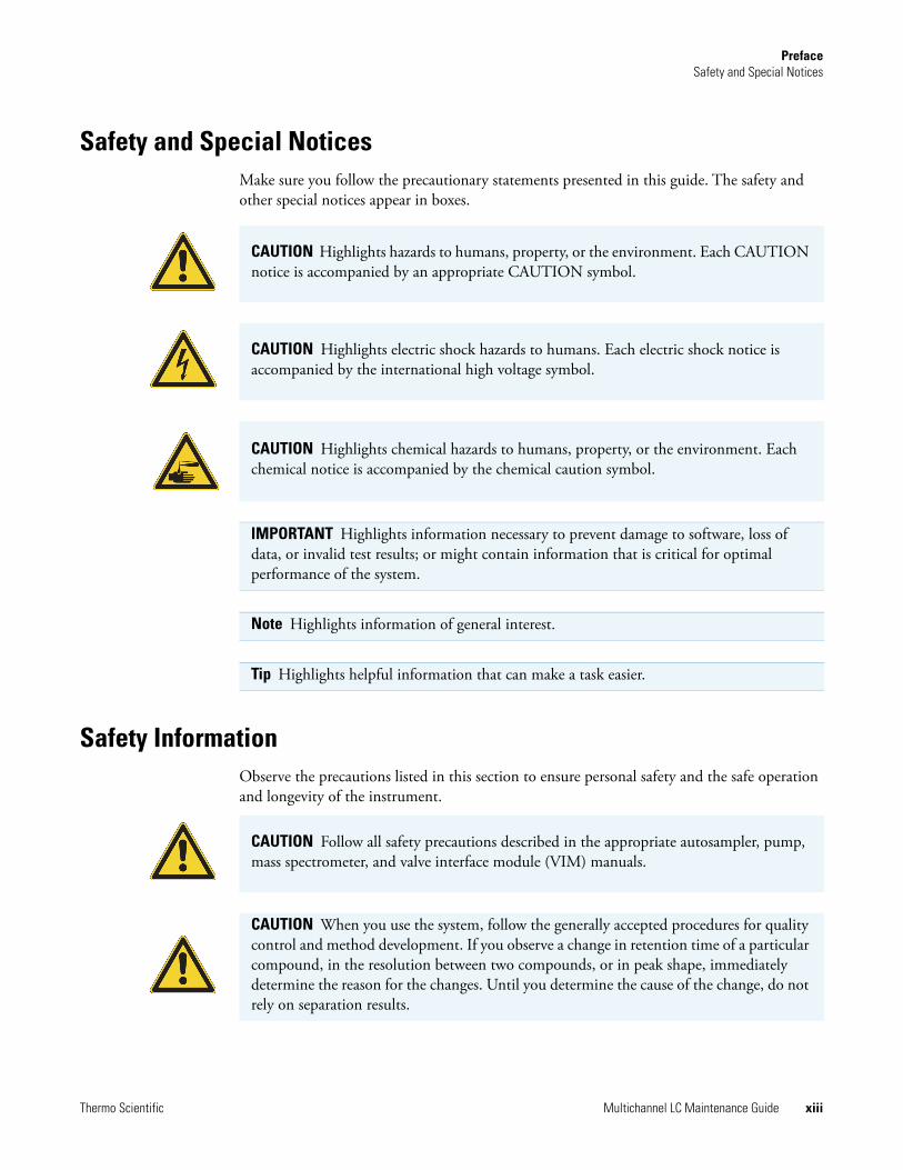
Safety and Special NoticesMake sure you follow the precautionary statements presented in this guide. The safety and other special notices appear in boxes.
Safety InformationObserve the precautions listed in this section to ensure personal safety and the safe operation and longevity of the instrument.
CAUTION Highlights hazards to humans, property, or the environment. Each CAUTION notice is accompanied by an appropriate CAUTION symbol.
CAUTION Highlights electric shock hazards to humans. Each electric shock notice is accompanied by the international high voltage symbol.
CAUTION Highlights chemical hazards to humans, property, or the environment. Each chemical notice is accompanied by the chemical caution symbol.
IMPORTANT Highlights information necessary to prevent damage to software, loss of data, or invalid test results; or might contain information that is critical for optimal performance of the system.
Note Highlights information of general interest.
Tip Highlights helpful information that can make a task easier.
CAUTION Follow all safety precautions described in the appropriate autosampler, pump, mass spectrometer, and valve interface module (VIM) manuals.
CAUTION When you use the system, follow the generally accepted procedures for quality control and method development. If you observe a change in retention time of a particular compound, in the resolution between two compounds, or in peak shape, immediately determine the reason for the changes. Until you determine the cause of the change, do not rely on separation results.

PrefaceSafety Information
xiv Multichannel LC Maintenance Guide Thermo Scientific
CAUTION Use equipment only in the manner specified by its manufacturer, or risk impairing the protection provided by the equipment.
CAUTION Do not service any part when operating the Prelude SPLC instrument. Do not remove or open the instrument front panels when the instrument is running.
CAUTION Place only safety-certified equipment, such as the Transcend II solvent rack and Transcend II pumps, on top of the Transcend II VIM. Fluid-carrying components, such as baking trays, lab ware, and flasks, are not permissible, and might damage the system.
CAUTION The instrument contains voltage lines. Switch off the power and disconnect the power cable prior to servicing any component on the system. There is no need to open the pump or VIM enclosure, as all user serviceable components are outside of the instruments.
CAUTION Follow the maintenance procedures in this manual when replacing or repairing serviceable components. Never try to repair or replace components not described in this manual without the assistance of a Thermo Fisher Scientific representative.
CAUTION Observe safe laboratory practices and procedures when handling chemicals. Only work with volatile chemicals under a fume or exhaust hood. Wear gloves and other protective equipment, as appropriate, when handling toxic, carcinogenic, mutagenic, corrosive, or irritant chemicals. Use approved containers and proper procedures to dispose of waste oil and when handling wetted parts of the instrument. Consult the pertinent safety data sheets (SDSs) for the solvents you use for HPLC analysis.
CAUTION Do not run the Prelude SPLC system with the autosampler door open. The autosampler contains a sharp moving part, which can cause injury if the door is opened during operation.
CAUTION For instruments that use biological reagents or samples, ensure that all operators are trained to safely work with biological hazards and that they wear protective clothing, including gloves and masks.

PrefaceSafety Information
Thermo Scientific Multichannel LC Maintenance Guide xv
Follow these safety precautions for TLX and LX systems.
CAUTION Allow any heated components to cool before touching them.
CAUTION Do not use a damaged or expired TurboFlow or HPLC column on the system. Run a preview batch at regular intervals to evaluate the quality of the TurboFlow and HPLC columns.
CAUTION Inaccurate data can result from samples that are placed in the wrong tray position. Verify that the sample vial position matches the assigned position in the batch or sequence file and that the sample trays are placed correctly into the sample drawers.
CAUTION The TLX-4 system uses two (2) power cords. Before servicing the instrument, unplug both power cords from line power. To safely connect and disconnect the system from line power, place the system as close as possible to the laboratory AC power outlet.
CAUTION When working with solvents, follow the guidelines in the solvent’s safety data sheet (SDS). Never refill one of the system’s solvent containers without first removing the container from the system.

PrefaceEnvironmental Conditions
xvi Multichannel LC Maintenance Guide Thermo Scientific
Environmental ConditionsRefer to the system component manuals for information on environmental conditions and specifications.
Good Laboratory PracticesTo obtain optimal performance from your LC system and to prevent personal injury or harm to the environment, do the following:
• Keep good records.
• Read the manufacturers’ MSDSs for the chemicals you use in your laboratory.
• Remove particulate matter from your samples before injecting them into the liquid chromatograph.
• Use LC/MS-grade solvents or better.
• Connect the drainage tubes from the pump, autosampler, and detector to an appropriate waste receptacle. Dispose of solvents as specified by local regulations.
Keeping Good Records
To help identify and isolate problems with either your equipment or your methodology, keep good records of all system conditions (for example, %RSDs on retention times and peak areas, peak shape, and resolution). At a minimum, thoroughly document a chromatogram of a typical sample and standard mixture, with system conditions, for future reference. Careful comparison of retention times, peak shapes, peak sensitivity, and baseline noise can provide valuable clues to identifying and solving future problems.
Chemical Toxicity
Although the large volume of toxic and flammable solvents used and stored in laboratories can be quite dangerous, do not ignore the potential hazards posed by your samples. Take special care to read and follow all precautions that ensure proper ventilation, storage, handling, and disposal of both solvents and samples. Become familiar with the toxicity data and potential hazards associated with all chemicals by referring to the manufacturers’ MSDSs.

PrefaceGood Laboratory Practices
Thermo Scientific Multichannel LC Maintenance Guide xvii
Solvent Requirements
Use LC/MS-grade solvents that are free of particulates. Choose a mobile phase that is compatible with the sample and column you have selected for your separation. Be aware that some solvents are corrosive to stainless steel.
Solvent Disposal
Make sure you have a solvent waste container or other kind of drain system available at or below the bench top level. Most solvents have special disposal requirements prohibiting disposal directly down a drain. Follow all governmental regulations when disposing of any chemical.
High-Pressure Systems and Leaks
LC systems operate at high pressures. There is little immediate danger from the high pressures in an LC system. However, if a leak occurs, correct it as soon as possible. Always wear eye and skin protection when operating or maintaining an LC system. Always shut down the system and return it to atmospheric pressure before attempting any maintenance.
CAUTION Do not use solvents containing Freon™ and perfluorinated solvents, such as Fluorinert™ and Fomblin™ perfluoro polyether solvents. They adversely affect the Teflon™ AF degassing membrane.
CAUTION Thermo Fisher Scientific recommends wearing safety glasses and lab coats when operating a multichannel LC system.
PrefaceContacting Us
xviii Multichannel LC Maintenance Guide Thermo Scientific
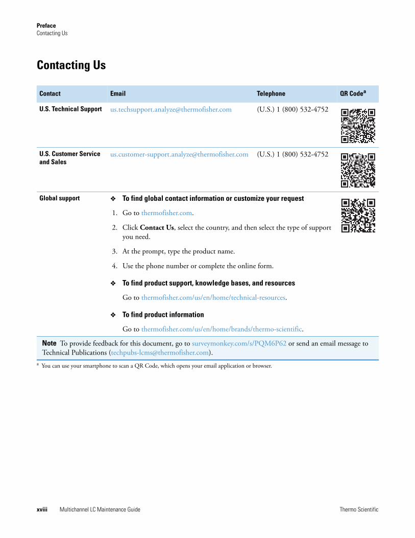
Contacting Us
Contact Email Telephone QR Codea
U.S. Technical Support [email protected] (U.S.) 1 (800) 532-4752
U.S. Customer Service and Sales
[email protected] (U.S.) 1 (800) 532-4752
Global support To find global contact information or customize your request
1. Go to thermofisher.com.
2. Click Contact Us, select the country, and then select the type of support you need.
3. At the prompt, type the product name.
4. Use the phone number or complete the online form.
To find product support, knowledge bases, and resources
Go to thermofisher.com/us/en/home/technical-resources.
To find product information
Go to thermofisher.com/us/en/home/brands/thermo-scientific.
Note To provide feedback for this document, go to surveymonkey.com/s/PQM6P62 or send an email message to Technical Publications ([email protected]).
a You can use your smartphone to scan a QR Code, which opens your email application or browser.

Thermo Scientific Multichannel LC Maintenance Guide 1
1
Maintenance Schedule
The use of this maintenance guide assumes the following:
• One of the LC systems listed in the Preface is running samples in a Research Use Only (RUO) environment.
• The installed Aria MX software is controlling LC sample processing and passing samples to a mass spectrometer system.
• The installed data system software is the appropriate version and is running properly.
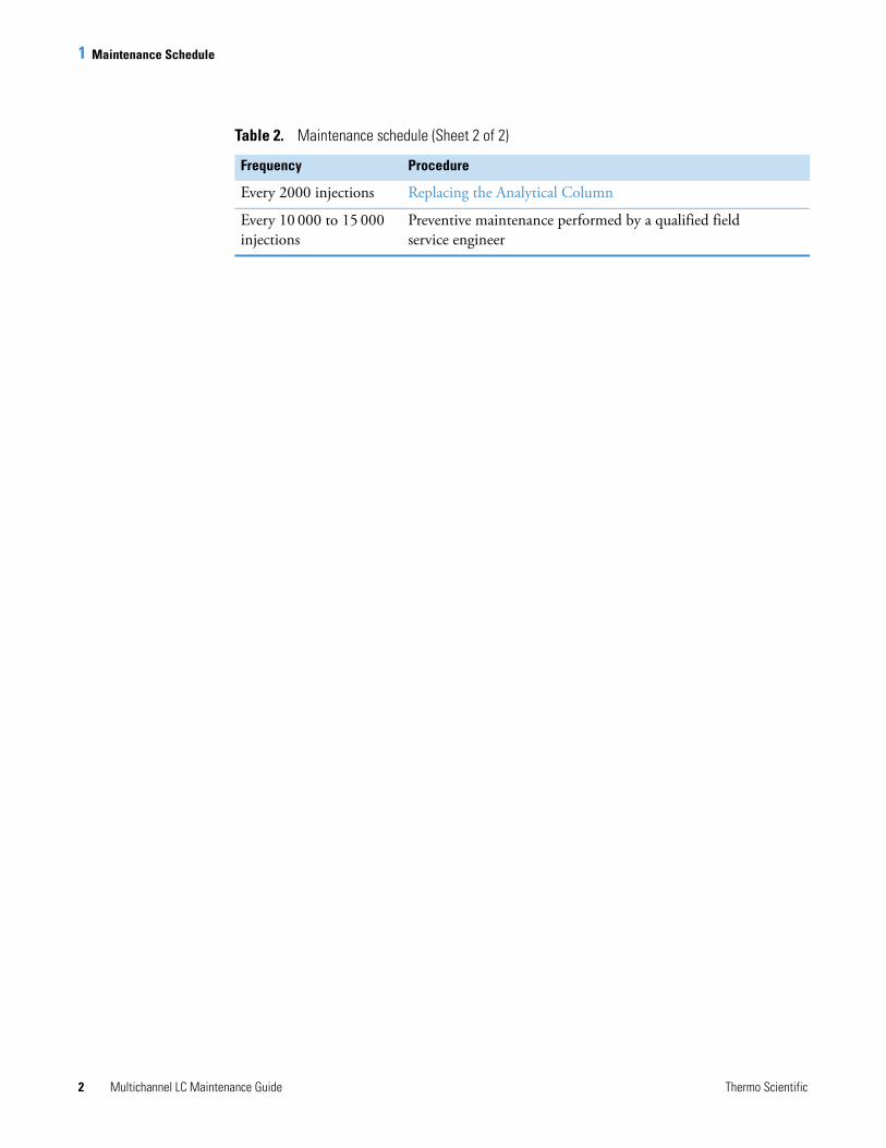
Adhering to the recommended maintenance schedule is an important part of keeping your system operating at peak efficiency and reliability. Table 2 summarizes important maintenance tasks and breaks them down to their corresponding recommended frequency.
Table 2 provides the schedule for performing system maintenance procedures.
IMPORTANT Schedule preventive maintenance with your Thermo Fisher Scientific field service engineer every 10 000 to 15 000 injections per LC channel.
Table 2. Maintenance schedule (Sheet 1 of 2)
Frequency Procedure
Daily Accessing the Direct Control Window
Tracking the Number of Injections
Managing the LC Pumps
Preparing the Mobile Phase Solvents
Priming the Dynamic Load Wash (DLW) Wash System
Priming the TriPlus LCMS-P Tool Wash Pumps
Rinsing the Needle on Systems with a Dynamic Load Wash (DLW)
Weekly Preparing Solutions
Every 300 to 1000 injections
Replacing the TurboFlow Column
1 Maintenance Schedule
2 Multichannel LC Maintenance Guide Thermo Scientific
Every 2000 injections Replacing the Analytical Column
Every 10 000 to 15 000 injections
Preventive maintenance performed by a qualified field service engineer
Table 2. Maintenance schedule (Sheet 2 of 2)
Frequency Procedure

Thermo Scientific Multichannel LC Maintenance Guide 3
2
Preparing Solutions
Your system requires various solutions that you must prepare properly for optimal performance and effective maintenance.
Contents
• Preparing the TurboFlow Column Wash Solvent
• Preparing the Mobile Phase Solvents
• Preparing the Rear Seal Wash Solution
• Preparing the Autosampler Wash Solutions
Preparing the TurboFlow Column Wash SolventThe column wash solvent is generally placed in mobile phase position C (or D) for the TurboFlow loading pump. It is used to wash a TurboFlow column while analytes are eluting from the analytical column to the MS. At a minimum, prepare the column wash solvent weekly.
Prepare a 45/45/10 acetonitrile/isopropanol/acetone solution in a clean 2-liter bottle by mixing the following:
• 900 mL of LC/MS-grade acetonitrile
• 900 mL of LC/MS-grade isopropanol
• 200 mL of LC/MS-grade acetone
Use this solution to fill the column wash solvent reservoir. The solution is stable for 30 days at room temperature.
Note You can use column wash solvent as the autosampler's organic wash solution when carryover is an issue.
2 Preparing SolutionsPreparing the Mobile Phase Solvents
4 Multichannel LC Maintenance Guide Thermo Scientific
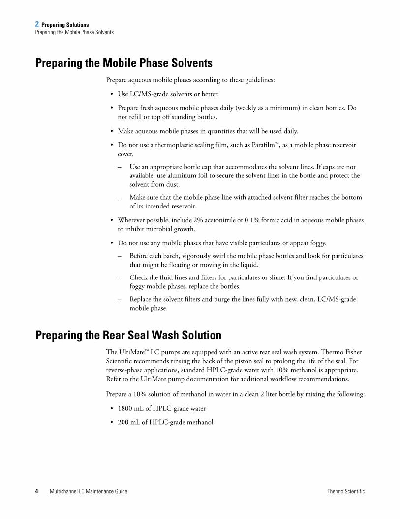
Preparing the Mobile Phase SolventsPrepare aqueous mobile phases according to these guidelines:
• Use LC/MS-grade solvents or better.
• Prepare fresh aqueous mobile phases daily (weekly as a minimum) in clean bottles. Do not refill or top off standing bottles.
• Make aqueous mobile phases in quantities that will be used daily.
• Do not use a thermoplastic sealing film, such as Parafilm™, as a mobile phase reservoir cover.
– Use an appropriate bottle cap that accommodates the solvent lines. If caps are not available, use aluminum foil to secure the solvent lines in the bottle and protect the solvent from dust.
– Make sure that the mobile phase line with attached solvent filter reaches the bottom of its intended reservoir.
• Wherever possible, include 2% acetonitrile or 0.1% formic acid in aqueous mobile phases to inhibit microbial growth.
• Do not use any mobile phases that have visible particulates or appear foggy.
– Before each batch, vigorously swirl the mobile phase bottles and look for particulates that might be floating or moving in the liquid.
– Check the fluid lines and filters for particulates or slime. If you find particulates or foggy mobile phases, replace the bottles.
– Replace the solvent filters and purge the lines fully with new, clean, LC/MS-grade mobile phase.
Preparing the Rear Seal Wash SolutionThe UltiMate™ LC pumps are equipped with an active rear seal wash system. Thermo Fisher Scientific recommends rinsing the back of the piston seal to prolong the life of the seal. For reverse-phase applications, standard HPLC-grade water with 10% methanol is appropriate. Refer to the UltiMate pump documentation for additional workflow recommendations.
Prepare a 10% solution of methanol in water in a clean 2 liter bottle by mixing the following:
• 1800 mL of HPLC-grade water
• 200 mL of HPLC-grade methanol

2 Preparing SolutionsPreparing the Autosampler Wash Solutions
Thermo Scientific Multichannel LC Maintenance Guide 5
Preparing the Autosampler Wash Solutions To prepare the autosampler wash solution
1. Prepare the autosampler wash solutions according to your laboratory’s standard operating procedure.
2. Follow the same general recommendations as described in Preparing the Mobile Phase Solvents.
3. Replace the old wash solution with freshly prepared solution.
4. Prime the pumps. See Chapter 3 for more information on priming the types of pumps used in your system.
IMPORTANT Make sure that you place the wash solution bottles in the appropriate locations. Improper locations of Wash 1 and Wash 2 can affect data quality.
IMPORTANT Thermo Fisher Scientific recommends that you properly revalidate LCMS methods when making any changes to AS wash solvents within an existing assay.

2 Preparing SolutionsPreparing the Autosampler Wash Solutions
6 Multichannel LC Maintenance Guide Thermo Scientific

Thermo Scientific Multichannel LC Maintenance Guide 7
3
Aria MX Software-based Maintenance
The Transcend II, Transcend, and Prelude SPLC systems rely on the Aria MX software to control and manage the system components—autosamplers, injectors, pumps, and so on.
The Aria MX software is also used to develop the instrument method instructions for the system components to run samples. Refer to the Aria MX User Guide and Help for details.
This chapter describes LC system maintenance procedures that are performed by using Aria MX software controls.
Contents
• Accessing the Direct Control Window
• Tracking the Number of Injections
• Managing the LC Pumps
• Seal Wash Pump Standby (Power Save Mode) for Transcend II Systems
Accessing the Direct Control WindowUse the Aria MX Direct Control window to perform many important maintenance tasks on the LC system. Depending on your system type—either Transcend/Aria or Prelude—the Aria MX Direct Control window will have different visual elements and controls.
To access the Direct Control window
Choose Start > All Programs > Thermo Instruments > Aria MX > Direct Control.

3 Aria MX Software-based MaintenanceAccessing the Direct Control Window
8 Multichannel LC Maintenance Guide Thermo Scientific
The Direct Control window appears. See Figure 3 for Transcend and Aria systems. See Figure 4 for Prelude SPLC systems.
Figure 3. Aria MX Direct Control window for Transcend and Aria systems

3 Aria MX Software-based MaintenanceTracking the Number of Injections
Thermo Scientific Multichannel LC Maintenance Guide 9
Figure 4. Aria MX Direct Control window for the Prelude SPLC system
Tracking the Number of InjectionsIt is important to keep good records and track the usage of syringes and other system components. The Aria MX Maintenance dialog box helps you optimize instrument performance by tracking the number of injections made by each probe or system.
To view the total number of injections on a probe, system, or detector
1. Open the Direct Control window.
2. Choose Tools > Maintenance.
The Maintenance dialog box appears (see Figure 5).

3 Aria MX Software-based MaintenanceTracking the Number of Injections
10 Multichannel LC Maintenance Guide Thermo Scientific
Figure 5. Maintenance dialog box
Table 3 describes the columns in the Maintenance dialog box.
Table 3. Maintenance dialog box columns
Column Description
Master The total, cumulative number of injections for each component.
Reference A user-defined interval of injections for tracking the number of injections for a system component. For example, define a reference named “TurboFlow column,” and install a new column. At the start of the reference, the count shows 0. Reset the count to zero each time you change the TurboFlow column. You can use this reference to determine the number of injections since the column was changed (see To create a reference for tracking injections).
Count The number of injections that have elapsed since the reference was created or reset to 0.
Limit The number of injections that must elapse before the system alerts you with a message.

3 Aria MX Software-based MaintenanceTracking the Number of Injections
Thermo Scientific Multichannel LC Maintenance Guide 11
A reference is the component or group of components that you want to track.
To create a reference for tracking injections
1. Select the system component that you want to track in the upper portion of the Maintenance dialog box.
2. Click Add.
The Add Maintenance Reference dialog box appears.
Figure 6. Add Maintenance Reference dialog box
3. Type a name for the reference. Enter a name that reflects the component you are tracking, such as Detector.
4. In the Warning Limit box, do one of the following:
• To have the system notify you when a specific number of injections that involve the selected component has elapsed, type the number of injections.
• To not have the system notify you when a number of injections have elapsed using the component, leave the box value set to 0.
5. To apply the setting across all channels for similar components, select the Apply Across All check box.
With this check box selected, an injection on any of the channels updates the count for this reference.
6. Click OK.
To reset a reference count to zero
1. In the Maintenance dialog box, select the reference name at the bottom of the window.
2. Click Reset.

3 Aria MX Software-based MaintenanceManaging the LC Pumps
12 Multichannel LC Maintenance Guide Thermo Scientific
3. To confirm the change, click Yes.
The count value for the selected reference resets to 0.
Managing the LC PumpsProper management of the system LC pumps requires basic daily maintenance checks. The following sections provide maintenance best practices and procedures.
Priming the LC Pumps for Transcend Systems
This procedure flows fluid from the solvent bottle to the pump and then to waste for Transcend system LC pumps. The fluids do not reach the columns in the priming procedure.
Prime the loading and eluting pumps if any of the following conditions occur:
• A pump solvent reservoir has emptied
• You changed the solvents on the system
• A pump has been idle for more than 24 hours
• You observe fluctuations in pump pressure
Prime the pumps using the mobile phases that you use for sample analysis, unless you are instructed to use a cleaning solvent or water during a troubleshooting or maintenance procedure.
To prime the LC pumps for Transcend systems
1. If the pump purge valve is not already connected to a waste reservoir, connect one end of the tubing to the waste outlet on the purge valve of the target pump. Place the other end of the tubing in the waste reservoir.
2. Open the Direct Control window. See “Accessing the Direct Control Window” on page 7.
3. In the middle pane, select the channel that you want to prime (see Figure 7 on page 13).
The pump control boxes appear:
• The loading pump boxes appear at the top of the window.
• The eluting pump boxes appear below the loading pump boxes.

3 Aria MX Software-based MaintenanceManaging the LC Pumps
Thermo Scientific Multichannel LC Maintenance Guide 13
Figure 7. Channel 1 in the Direct Control window
4. In the Flow Rate box in the loading pump area, enter the maximum flow rate recommended by the pump manufacturer.
5. If the pump has multiple channels, type 100 (%) for channel A in the loading pump area.
6. Choose Tools > Options.
The following dialog box appears (see Figure 8).
Figure 8. Options dialog box
7. In the LC Timeout box, type 5 minutes. Do not change the setting for the Pump Failsafe Override box. Then, click OK.
8. Open the pump purge valve by rotating it counterclockwise one or two revolutions.
9. In the Active list of the Direct Control window, select On to turn on the pump.
The pumps prime until the LC Timeout time has elapsed.
Note Depending on the make and model of the pumps on your system, the appearance of this window might be different.
Loading pump controls
Eluting pump controls

3 Aria MX Software-based MaintenanceManaging the LC Pumps
14 Multichannel LC Maintenance Guide Thermo Scientific
10. If you want to stop priming before the LC Timeout time has elapsed, select Off in the Active list.
11. Repeat step 8 through step 10 for each channel on the pump.
12. Repeat step 5 through step 11 for the eluting pump.
13. Close the purge valves.
Priming the LC Pumps for Prelude SPLC
If you observe fluctuations in pump pressure, change the solvent bottles, and then prime the pumps. If the instrument has been idle for more than 24 hours, prime the loading and eluting pumps.
This procedure flows fluid from the solvent bottle to the pump, and then to waste. The fluids do not reach the columns.
Prime the pumps using the mobile phases you use for sample analysis, unless a service engineer instructs you to use a cleaning solvent or water during a troubleshooting or maintenance procedure.
To prime the pumps using the controls in the Direct Control window
1. Open the Direct Control window.
2. Open the Prelude menu.
The Prelude menu shows the available priming commands and options.
Note Because the purge valve is open, pump pressure is lower than when you run methods and should be close to zero.
Thermo Scientific Accela™ 600 and 1250 pumps normally show a backpressure of 5–15 bar when the purge valve is open. This backpressure is normal and the pump is purging and working properly. This 5–15 bar backpressure value is due to seal friction and is not an offset or miscalibration of the pressure reading or pressure sensors. As soon as the pump is put back under pressure, seal friction and the system show correct backpressure readings.
Note You can prime multiple pumps and systems at the same time.
Note Do not overtighten the purge valve.
Note For Prelude SPLC systems, Thermo Fisher Scientific recommends that you prime both channels at least six times using Bottle Set 1, and both channels at least six times using Bottle Set 2.

3 Aria MX Software-based MaintenanceManaging the LC Pumps
Thermo Scientific Multichannel LC Maintenance Guide 15
Figure 9. Prelude menu options
Use one of the following options to initiate the priming operation.
(Option 1) To prime all the pumps at the same rate by using the controls in the Direct Control window
1. Open the Direct Control window. See “Accessing the Direct Control Window” on page 7.
2. Choose Prelude > Prime All.
The Enter Desired Prime Quantity dialog box opens (see Figure 10).
Figure 10. Enter Desired Prime Quantity dialog box
3. Type the number of prime cycles that you want to perform, and then click Submit.
All of the system pumps begin the priming operation for the number of times that you specified.
(Option 2) To prime individual pumps in the Direct Control window
1. Open the Direct Control window. See “Accessing the Direct Control Window” on page 7.
2. Click Prime Control for any available channel from the middle pane of the Direct Control Window (see Figure 4).
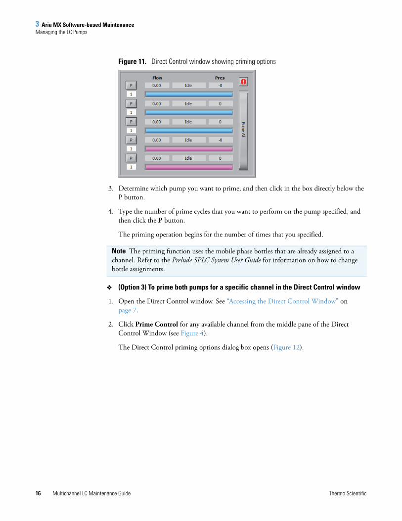
The Direct Control priming options dialog box opens (Figure 11).
Note The priming function uses the mobile phase bottles that are already assigned to a channel. Refer to the Prelude SPLC System User Guide for information on how to change bottle assignments.
Channel-specific (priming) commands
Priming commands
3 Aria MX Software-based MaintenanceManaging the LC Pumps
16 Multichannel LC Maintenance Guide Thermo Scientific
Figure 11. Direct Control window showing priming options
3. Determine which pump you want to prime, and then click in the box directly below the P button.
4. Type the number of prime cycles that you want to perform on the pump specified, and then click the P button.
The priming operation begins for the number of times that you specified.
(Option 3) To prime both pumps for a specific channel in the Direct Control window
1. Open the Direct Control window. See “Accessing the Direct Control Window” on page 7.
2. Click Prime Control for any available channel from the middle pane of the Direct Control Window (see Figure 4).
The Direct Control priming options dialog box opens (Figure 12).
Note The priming function uses the mobile phase bottles that are already assigned to a channel. Refer to the Prelude SPLC System User Guide for information on how to change bottle assignments.

3 Aria MX Software-based MaintenanceManaging the LC Pumps
Thermo Scientific Multichannel LC Maintenance Guide 17
Figure 12. Direct Control window showing priming options
3. Determine the channel with the pumps that you want to prime, and then click Prime All on the right.
The Enter Desired Prime Quantity dialog box opens (see Figure 13).
Figure 13. Enter Desired Prime Quantity dialog box
4. Type the number of prime cycles that you want to perform, and then click Submit.
The two pumps for that channel begin the priming operation for the number of times that you specified.
Recording Pump Pressures
Take daily note of the pump pressure about 15 seconds after the sample injection. Keep a log of the pressures every day and every time a new column is installed. Record the pressures on each channel with the columns in place. Refer to the Aria MX User Guide for details regarding monitoring the pump pressure.
Do the following:
• View the pressure trace of a recently run sample and compare it with a baseline pressure trace.
Note The priming function uses the mobile phase bottles that are already assigned to a channel. Refer to the Prelude SPLC System User Guide for information on how to change bottle assignments.
3 Aria MX Software-based MaintenanceManaging the LC Pumps
18 Multichannel LC Maintenance Guide Thermo Scientific
If you observe meaningfully higher pressure anywhere in the system, consider isolating the faulty component by process of elimination. Possible causes of a pressure increase include deteriorating or clogged columns, tubing, and rotor seals.
Check all visible fittings for signs of leaking if you observe significantly lower pressure anywhere in the system. Additionally, verify that the column heaters are functioning correctly, if installed.
• Call Thermo Fisher Technical Support if you are unable to resolve the problem (see “Contacting Us” on page xviii).
Purging Thermo Scientific UltiMate Pumps (Transcend II systems)
For best results, allow Thermo Scientific UltiMate pumps to run an internal maintenance procedure every 45 days, which lubricates the internal pump mechanisms, including the pump cam tracks.
UltiMate pumps display a warning message if no purge operation has been initiated within 90 days. The pumps indicate a persistent error state after 150 days, until a maintenance purge has been completed. You can also view relevant messages regarding the UltiMate pump from the Aria MX status pane at the bottom of the Aria MX Direct Control window (see Figure 14).
Key aspects of the purge feature include the following:
• You can perform a manual pump purge at any time. The pump firmware automatically runs the maintenance procedure during a manual purge if it has been at least 45 days since the last lubrication.
• The pump firmware tracks the date of the last cam track lubrication procedure along with the warning and the limit dates, which are visible from the Aria MX Direct Control window.
• The cam track lubrication timer is set in the UltiMate pump firmware and is reset whenever the pumps perform the maintenance procedure.
• Pump purges performed before the 45-day time period has elapsed do not include the cam lubrication function.
• Pump purges performed after the 45-day time period has elapsed also include the cam track lubrication function.
• Running the Purge command also primes the solvents.
IMPORTANT The purge procedure requires that you physically open the purge valves on each pump being purged.

3 Aria MX Software-based MaintenanceManaging the LC Pumps
Thermo Scientific Multichannel LC Maintenance Guide 19
Figure 14. Aria MX Direct Control window, pump view, with Purge button, cam track lubrication reminder, and status pane
Purge the UltiMate pumps periodically as part of routine maintenance. The pump firmware logs and tracks the purges based on a 45-day cycle.
To purge the UltiMate pump and reset the maintenance clock timer
1. Open the Aria MX Direct Control window. See “Accessing the Direct Control Window” on page 7.
2. From the middle pane of the Aria MX Direct Control window, select the channel and pump that you want to purge. See Figure 14.
3. Open the pump purge valves on the selected pump by rotating each valve counterclockwise one or two revolutions.
4. From the right pane of the Aria MX Direct Control window, click Purge or Run Maintenance & Purge, depending on which button is displayed.
Note The Purge button changes into the Run Maintenance & Purge button if more than 45 days have passed since the last purge. See Figure 14.
Pump number
Run
Cam track lubrication information
Status pane
Maintenance& Purge orPurge button

3 Aria MX Software-based MaintenanceManaging the LC Pumps
20 Multichannel LC Maintenance Guide Thermo Scientific
A warning message appears regarding the pump settings.
Figure 15. Purge setting warning message
5. Click Continue.
The purge operation begins without additional notification and continues for five minutes. The dark blue purge indicator displays the purge operation status in the Aria MX Direct Control window (see Figure 16).
Figure 16. Aria MX Direct Control window with blue Purging indicator
6. Close the pump purge valves after the Purging indicator changes from Purging to READY.
The pump purging process is complete, and the 45-day maintenance clock is reset for that pump.
Note The pump displays a message on the front panel when maintenance is being performed. You can cancel the purge operation once maintenance is complete.

3 Aria MX Software-based MaintenanceSeal Wash Pump Standby (Power Save Mode) for Transcend II Systems
Thermo Scientific Multichannel LC Maintenance Guide 21
Seal Wash Pump Standby (Power Save Mode) for Transcend II Systems
You can configure Transcend II UltiMate LC pumps to go into standby mode when they are not actively running samples. Doing so has the added benefit of turning off the rear seal wash system, which helps to reduce wash solvent consumption and save power.
When placed in standby mode, the pumps, including the LED control screens, turn off. You can turn the pumps back on using the Aria MX software.
Configuring Seal Wash Standby
Use the Foundation Instrument Configuration window to configure the rear seal wash standby mode for UltiMate pumps.
To set the rear seal wash standby mode
1. Choose Start > All Programs > Thermo Foundation x.x > Instrument Configuration.
The Instrument Configuration window opens.
2. From the Configured Devices pane, select Aria MX, and then click Configure.
The Configurations dialog box opens.
Figure 17. Configurations dialog box, Pumps option
3. Click Pumps.
The (pumps) Configurations dialog box appears (see Figure 18).
Note You must close all other Thermo Scientific data system applications before performing the following procedure.
Pumps option

3 Aria MX Software-based MaintenanceSeal Wash Pump Standby (Power Save Mode) for Transcend II Systems
22 Multichannel LC Maintenance Guide Thermo Scientific
Figure 18. Configurations dialog box, Thermo Ultimate Pumps option (selected)
4. Click Thermo Ultimate Pumps.
The Ultimate Pump configuration dialog box appears (Figure 19).
Figure 19. Bottom area of the Ultimate Pump configuration dialog box
5. Select the Enable Power Save check box.
The Power Save Timeout (min) box is activated.
6. Type the number of minutes that you want to set as the timeout time in the Power Save Timeout box, and then click OK.
Seal Wash Standby Options
The Power Save configuration parameters for the UltiMate pumps are set in the Ultimate Pump Configuration dialog box using the Thermo Foundation Instrument Configuration window.
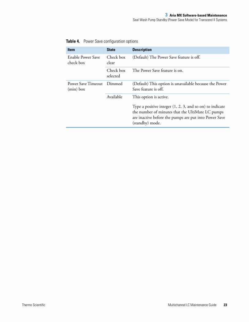
The Power Save Timeout feature has the following configuration options (see Table 4).
Note The Power Save Timeout timer starts after the LC timeout setting has been reached.
Power Save Timeout box, dimmed (deactivated state)
Enable Power Save check box
3 Aria MX Software-based MaintenanceSeal Wash Pump Standby (Power Save Mode) for Transcend II Systems
Thermo Scientific Multichannel LC Maintenance Guide 23
Table 4. Power Save configuration options
Item State Description
Enable Power Save check box
Check box clear
(Default) The Power Save feature is off.
Check box selected
The Power Save feature is on.
Power Save Timeout (min) box
Dimmed (Default) This option is unavailable because the Power Save feature is off.
Available This option is active.
Type a positive integer (1, 2, 3, and so on) to indicate the number of minutes that the UltiMate LC pumps are inactive before the pumps are put into Power Save (standby) mode.

3 Aria MX Software-based MaintenanceSeal Wash Pump Standby (Power Save Mode) for Transcend II Systems
24 Multichannel LC Maintenance Guide Thermo Scientific

Thermo Scientific Multichannel LC Maintenance Guide 25
4
Autosampler Maintenance
This chapter describes maintenance guidelines and procedures for the Thermo Scientific Accela Open and TriPlus™ autosamplers.
Contents
• Supported Autosampler Models
• Verifying Wash Solutions
• Syringe and Needle Maintenance
• Downloading Autosampler Objects to Aria MX (Accela Open)
• Priming the Dynamic Load Wash (DLW) Wash System
• Priming the TriPlus LCMS-P Tool Wash Pumps
Supported Autosampler ModelsAria MX software, version 2.3, supports two autosampler models:
• Accela Open—Used in Transcend II and Transcend systems.
• TriPlus RSI—Used in some Transcend II and Transcend systems shipped in 2017 and later.
You can use only one autosampler type for each data system computer to process samples. Use Thermo Foundation Instrument Configuration to set the type of autosampler that your system is running.
For more information, browse the Autosamplers folder on the Aria MX DVD and refer to the documentation that is located inside the folder corresponding to your autosampler model.
Note There are some differences in the maintenance procedures for each model of autosampler. Follow the procedures that are specific to the autosampler model that you are using in your LC system.

4 Autosampler MaintenanceVerifying Wash Solutions
26 Multichannel LC Maintenance Guide Thermo Scientific
Verifying Wash SolutionsVerify the wash solutions used in the system to ensure their freshness and overall integrity. The following sections provide instructions on how to verify the wash solutions for the Accela Open and TriPlus autosamplers.
• Verifying Wash Solutions for the Accela Open Fast Wash Stations
• Verifying Wash Solutions for the TriPlus
Verifying Wash Solutions for the Accela Open Fast Wash Stations
Legacy Accela Open autosamplers configured with a Fast Wash module use a solvent bottle that contains a valve located at the bottom of the bottle. Dynamic Load Wash (DLW) systems use solvent bottles that have top caps and filters.
The following procedure describes how to check the Accela Open autosampler fast wash solutions to verify correct placement.
To verify the Accela Open autosampler wash solutions
1. Verify that all wash bottles on the autosampler wash stations are full.
2. Verify that the aqueous wash is in Bottle 1 and that it is connected to the port for Wash 1 on the wash station.
3. Verify that the organic wash is in Bottle 2 and that it is connected to the port for Wash 2 on the wash station.
4. Swirl the wash bottles and look for any particulates. Discard the liquid and wash the bottle if you see particulates or if the liquid appears cloudy.
5. Verify that the valves on the bottles are open and the cap is loose. If the valves are parallel with the tubing, they are open (see Figure 20).
IMPORTANT
• Make sure wash solution levels are full, and that any wash filters are properly located at the bottom of the wash solvent bottle.
• Running out of wash solutions on either a DLW or LCMS-P module during a run will affect data quality.
• Running out of wash solutions during a run can allow for organic solvent to mix with biological samples, which can cause precipitation and system clogs.
CAUTION Handle the glass nipple on the base of the autosampler wash bottles with care to avoid breakage and injury.

4 Autosampler MaintenanceVerifying Wash Solutions
Thermo Scientific Multichannel LC Maintenance Guide 27
Figure 20. Fast Wash bottle valves (open) for Accela Open autosamplers
6. Loosen the valve fittings on the wash station by turning them counterclockwise and verify that the liquid flows freely (see Figure 21).
Figure 21. Valve fittings on the Fast wash station for Accela Open autosamplers
7. Close the fittings.
Verifying Wash Solutions for the TriPlus
This procedure describes how to check the TriPlus autosampler wash solutions to verify correct placement.
To verify the TriPlus autosampler wash solutions
1. Verify that all wash bottles on the autosampler wash stations are full.
2. Verify that the aqueous wash is in Bottle 1 and that it is connected to the port for Wash 1 on the wash station.
IMPORTANT
• Running out of wash solutions on either a DLW or LCMS-P module during a run will affect data quality.
• Make sure wash solution levels are full, and that any wash filters are properly located at the bottom of the wash solvent bottle.
• Running out of wash solutions during a run can allow for organic solvent to mix with biological samples, which can cause precipitation and system clogs.

4 Autosampler MaintenanceSyringe and Needle Maintenance
28 Multichannel LC Maintenance Guide Thermo Scientific
3. Verify that the organic wash is in Bottle 2 and that it is connected to the port for Wash 2 on the wash station.
4. Verify that the filter is properly attached to the tubing and that the bottle cap is closed correctly.
5. Swirl the wash bottles and look for any particulates. Discard the liquid and wash the bottle if you see particulates or if the liquid appears cloudy.
Syringe and Needle MaintenanceThe following sections provide information on how to maintain syringes and needles for systems that use the Accela Open or TriPlus autosamplers.
• Accela Open Syringe and Needle Replacement
• TriPlus Syringe and Needle Replacement
Accela Open Syringe and Needle Replacement
The following sections provide details on how to properly maintain the system syringes and needles in the Accela Open autosampler.
Replacing the Standard or X-Type Syringes
Perform this procedure to replace a standard or X-type syringe every 15 000 injections. If your system uses the DLW, see “Replacing the Dynamic Load Wash (DLW) Needle on the Accela Open Autosampler” on page 31.
To replace a standard or X-type syringe
1. Verify that the system has stopped sampling, and open the Direct Control window (see Figure 22).
2. Select the appropriate autosampler and click Unlock Terminal.
The Change Syringe option appears.

4 Autosampler MaintenanceSyringe and Needle Maintenance
Thermo Scientific Multichannel LC Maintenance Guide 29
Figure 22. Direct Control window showing the Change Syringe option (Accela Open)
3. Select the Change Syringe option.
The autosampler arm moves to a default position so that the syringe can be changed.
4. Lift the clear door to gain access to the syringe and syringe holder.
5. Loosen the red thumb screw that holds the syringe plunger in place (see Figure 23).
Figure 23. Accela Open autosampler syringe
6. Turn the black locking bar that holds the syringe barrel in place.
7. Pull the syringe out and up to remove it. Discard it appropriately.
8. Carefully place the new syringe into the arm. Place the flat side of the syringe barrel collar against the syringe holder.
9. Verify the syringe plunger is seated in the plunger holder where the red thumb screw is located.
10. Turn the black locking bar to hold the syringe barrel in the holder.
Red thumb screw
Syringe barrel collar
Black locking bar

4 Autosampler MaintenanceSyringe and Needle Maintenance
30 Multichannel LC Maintenance Guide Thermo Scientific
11. Tighten the red thumb screw to secure the plunger in the holder.
12. Click OK.
The probe moves to the home position. The autosampler senses the new syringe size and updates the Aria MX software.
Continue by setting the Needle Penetration level. See Setting the Needle Penetration Level.
Replacing the Syringe Plunger
Replace the syringe plunger every 1500 injections. See “Replacing the Standard or X-Type Syringes” on page 28.
Setting the Needle Penetration Level
Set the needle penetration level whenever you change the syringe needle or if instructed to do so by a Thermo Fisher Scientific service engineer as part of a troubleshooting process.
If your system uses a DLW, see “Setting the Needle Penetration Value for the DLW on the Accela Open Autosampler” on page 32.
To set the Accela Open autosampler needle penetration level
1. Open the Direct Control window.
2. Select the appropriate autosampler and click Unlock Terminal.
3. Locate the handheld keypad that controls the autosampler of the syringe you replaced.
4. From the main menu of the keypad, press F1 (Menu).
5. Rotate the dial to highlight Utilities. Press the dial button located at the center of the dial.
6. Rotate the dial to highlight Injector. Press the dial button.
7. Rotate the dial to highlight the injector that you want to calibrate, and then press the dial button.
8. Press F3 (Movto Inj).
The autosampler moves from the home position to the selected injector valve.
9. Press the dial button.
The needle moves down into the valve.
Note If you hear a clunk when the needle moves into the valve, the needle might have reached the bottom of the valve. Turn the dial (counterclockwise) to move the needle up until you see the syringe move up about 0.6 cm. Press the dial button to accept the value and then continue from step 5.

4 Autosampler MaintenanceSyringe and Needle Maintenance
Thermo Scientific Multichannel LC Maintenance Guide 31
10. Rotate the knob clockwise until you hear a clunk.
The needle lowers into the valve as you rotate the dial.
11. Make a note of the needle penetration value indicated on the CTC keypad.
12. Rotate the knob counterclockwise two clicks.
The needle moves up 0.2 mm.
13. Verify that the needle penetration value on the CTC keypad is 0.2 mm less than the value you noted in step 9.
For example, if the needle penetration value was 24.6 mm when you heard the clunk, dial the needle up until the needle penetration value is 24.4 mm.
14. Press the dial button to accept the value.
15. Repeat step 6 through step 12 to confirm the needle penetration value.
16. Repeat step 3 through step 13 for each valve that is serviced by the replacement syringe.
17. Repeat step 1 through step 14 for each syringe that you replaced.
18. When the needle penetration value is acceptable for all autosampler injector valves, press F4 (Home) to return to the main screen of the keypad.
19. Update the Aria MX software with the new objects from the autosampler. See “To download objects to the Aria MX application” on page 45, and then lock the terminal.
Replacing the Dynamic Load Wash (DLW) Needle on the Accela Open Autosampler
Use this procedure to replace the needle on the Accela Open autosampler if your system uses the DLW.
To replace a DLW needle on systems equipped with an Accela Open autosampler
1. From the Direct Control window, select the appropriate autosampler. See “Accessing the Direct Control Window” on page 7.
2. Click Unlock Terminal.
Note If you do not hear a clunk when you lower the needle and the penetration value does not change, contact Thermo Fisher Scientific Technical Support.

4 Autosampler MaintenanceSyringe and Needle Maintenance
32 Multichannel LC Maintenance Guide Thermo Scientific
The Change Syringe option appears. See Figure 22 on page 29.
3. Select the Change Syringe option.
The autosampler arm moves to a default position so that the syringe can be changed.
4. To change the syringe, refer to the documentation and instructions for changing a DLW needle provided with the autosampler.
5. In the confirmation box, click OK.
The probe moves to the home position. The autosampler senses the new syringe size and updates the Aria MX software.
Continue by setting the needle penetration level. See Setting the Needle Penetration Value for the DLW on the Accela Open Autosampler.
Setting the Needle Penetration Value for the DLW on the Accela Open Autosampler
Set the needle penetration level whenever you change the DLW needle or if instructed to do so by a Thermo Fisher Scientific service engineer as part of a troubleshooting process.
To set the needle penetration value for the DLW (Accela Open)
1. Open the Direct Control window.
2. Select the appropriate autosampler and click Unlock Terminal.
3. Locate the handheld keypad that controls the autosampler of the syringe you replaced.
4. From the main menu of the keypad, press F1 (Menu).
5. Rotate the dial to highlight Utilities. Press the dial button located at the center of the dial.
6. Rotate the dial to highlight Injector. Press the dial button.
7. Rotate the dial to highlight the injector that you want to calibrate. Press the dial button.
8. Press F3 (Movto Inj).
The autosampler moves from the home position to the selected injector valve.
9. Press the dial button.
The needle moves down into the valve.
10. Rotate the dial clockwise or counterclockwise until the bottom of the cross bar of the DLW needle holder assembly is flush with the lower line of the DLW needle adapter
CAUTION Calibrating the autosampler requires removal of the slide plate and visual inspection of the autosampler needle holder. Because the autosampler compartments contain moving parts and sharp needles, make sure to keep hands clear when operating the autosampler during calibration.

4 Autosampler MaintenanceSyringe and Needle Maintenance
Thermo Scientific Multichannel LC Maintenance Guide 33
block. Verify that both sides of the cross bar are flush with the DLW needle adapter block. See Figure 24.
Figure 24. DLW needle holder assembly cross bar and needle adapter block
11. Press the dial button to accept the value.
12. Press ESC.
The needle moves to the home position.
13. Repeat step 7 through step 12 to verify the value.
14. Repeat step 7 through step 13 for each valve that the DLW services.
15. Repeat step 1 through step 14 for each syringe that you replaced.
16. When the needle penetration value is acceptable for all autosampler injector valves, press F4 (Home) to return to the main screen of the keypad.
17. Update the Aria MX software with the new objects from the autosampler, and then lock the terminal. See “Downloading Autosampler Objects to Aria MX (Accela Open)” on page 45.
Replacing the DLW Syringe on Systems Equipped with the Accela Open Autosampler
Replace the DLW syringe on systems that are equipped with the Accela Open autosampler when a Thermo Fisher Scientific service engineer recommends it as part of a troubleshooting procedure.
To replace the DLW syringe (Accela Open)
1. From the Direct Control window, select the appropriate autosampler. See “Accessing the Direct Control Window” on page 7.
2. Click Unlock Terminal.
The Change Syringe option appears. See Figure 22 on page 29.
3. Select the Change Syringe option.

4 Autosampler MaintenanceSyringe and Needle Maintenance
34 Multichannel LC Maintenance Guide Thermo Scientific
The autosampler arm moves to a default position so that you can change the syringe.
4. Unscrew the red bushing on the plunger carriage until the plunger cap is no longer engaged.
Figure 25. DLW syringe showing the red bushing and thumbscrew
5. Unscrew the thumbscrew on front of the syringe holder. See Figure 25.
6. Tip the syringe holder forward at the top to disengage the magnets, and then slide the holder up so that the needle clears the needle guide.
7. If you are replacing the syringe barrel, unscrew the knurled collar at the bottom of the syringe barrel to remove the barrel from the assembly (see Figure 26). If you are not replacing the syringe barrel, continue with step 8.
Figure 26. DLW syringe showing the knurled collar
8. Pull the plunger out of the barrel. This can be done with or without the barrel in the assembly.
9. Using a T6 torx driver, loosen the set screw and remove the plunger cap (Figure 27).
Tip Perform the following steps with the assembly placed in front of or to the left of the probe so that you do not put tension on the wire or tubing.
Red bushing
Thumbscrew

4 Autosampler MaintenanceSyringe and Needle Maintenance
Thermo Scientific Multichannel LC Maintenance Guide 35
Figure 27. DLW syringe showing the location of the plunger cap
10. Insert the new plunger, with the yellow tip first, into the barrel and push it all the way to the stop.
11. Pull back the plunger a fraction of a millimeter to release pressure on the tip.
12. Place the plunger cap over the plunger, flush against the top of the barrel, and tighten the plunger cap set screw with the T6 torx driver.
13. If you removed the barrel from the assembly, replace it now by threading the barrel into the assembly and tightening the knurled collar at the bottom of the barrel.
14. Slant the assembly in at the bottom and thread the needle through the lower needle guide.
15. Push the top of the assembly back and engage the magnets to snap the assembly into the probe (see Figure 28).
Figure 28. Placing the needle assembly into the probe
16. Move the lower needle guide up and down to confirm that it is not catching on the needle tip.
17. Tighten the thumbscrew. See Figure 25.
4 Autosampler MaintenanceSyringe and Needle Maintenance
36 Multichannel LC Maintenance Guide Thermo Scientific
18. Click OK when prompted.
• The probe moves to the home position.
• The autosampler senses the new syringe size and updates the Aria MX software.
19. Calibrate the needle penetration for the probe in all valves that are accessed by the affected needle. See “Setting the Needle Penetration Value for the DLW on the Accela Open Autosampler” on page 32.
Setting the Tray Type Needle Penetration Level (Accela Open)
The tray type needle penetration level is the level in the vial or well at which the autosampler aspirates the sample. This level is set for each tray type and applies to all tray positions that use the tray type. You might want to change this value if you have varying sample amounts or settlement in the bottom of the vial or well.
To set the tray type needle penetration level (Accela Open)
1. From the Direct Control window, select the appropriate autosampler. See “Accessing the Direct Control Window” on page 7.
2. Click Unlock Terminal to activate the handheld controller.
3. Verify that the autosampler is on and the keypad shows the main screen with “Job Queue” at the top.
4. Press F1 (Menu).
The menu screen appears.
5. Rotate the dial on the keypad to highlight Utilities. Press the dial button located at the center of the dial.
6. Rotate the dial to highlight Tray and then press the button at the center of the dial.
A list of trays appears, for example, “Tray03.”
7. Rotate the dial to show the tray number for the tray type whose needle penetration level you want to adjust, and press the dial button.
8. Pull out the tray drawer you selected in step 6 until it is completely open.
Note If you want to set the tray type needle penetration level for a system that uses a DLW, see “Setting the Needle Penetration Value for the DLW on the Accela Open Autosampler” on page 32.

4 Autosampler MaintenanceSyringe and Needle Maintenance
Thermo Scientific Multichannel LC Maintenance Guide 37
9. Install a tray in the tray type drawer where you want to set the needle penetration level. If you are using vials, install a vial in position 001.
10. Verify that the type of tray in the drawer matches the tray type indicated on the keypad screen.
11. Rotate the dial to highlight Needle Penetr.
12. Press F3 (move to 001).
The autosampler moves to position 001.
13. Press the dial button.
The needle moves down into the well to the level where the sample is aspirated.
14. To aspirate the sample at the appropriate needle level, do the following:
• To raise () the needle, rotate the dial counterclockwise until the needle is at the appropriate level. The needle penetration value on the keypad decreases.
• To lower () the needle, rotate the dial clockwise until the needle is at the appropriate level. The needle penetration value on the keypad increases.
15. Press the dial button to accept the new needle penetration value for all wells in the selected tray type and all drawers that use the same tray type.
16. Press F4 (Home) to return to the main menu.
The needle penetration level is saved for all drawers that use the same tray type.
17. Start the Aria MX software.
18. Update the Aria MX software with the new objects from the autosampler, and then lock the terminal. See “Downloading Autosampler Objects to Aria MX (Accela Open)” on page 45.
Note You might need to modify vials or 96-well plates so that the needle level is visible. You can also fill the vial or well with water or methanol as a sample level reference.
Note If you want to change the tray type for the selected tray, rotate the dial to show Tray Type and press the dial button. Rotate the dial again to show the tray type that you want and press the dial button. Continue with step 9.
Note Set the tray type needle penetration at a level where the needle does not contact the bottom of the vial or well during aspiration.
If the needle stops moving downward as you continue to rotate the dial clockwise, the needle might have reached its maximum penetration limit. If you want to move the needle further, contact Customer Support (see “Contacting Us” on page xviii).

4 Autosampler MaintenanceSyringe and Needle Maintenance
38 Multichannel LC Maintenance Guide Thermo Scientific
Resetting the XYZ Positions (Accela Open)
Reset the XYZ positions if the autosampler arm is accidentally bumped.
To reset the XYZ Positions
1. Open the Direct Control window.
2. From the middle pane, select the autosampler arm that you want to reset.
The autosampler options appear on the right.
Figure 29. Direct Control window with autosampler options
3. Click the Reset icon, .
One of the following occurs:
• If the instrument is idle, the system resets positions, injectors, and the syringe. The autosampler then goes to the Home position.
• If the system is running a batch, the autosampler pauses the method, performs only the position reset, and then continues with the method. Thermo Fisher Scientific recommends pausing the autosampler before resetting it.
Cleaning the Syringe (Fast Wash Systems) for the Accela Open Autosampler
This procedure fills the syringe at the wash station and flushes the injector.
To clean the syringe for systems using Fast Wash
1. Open the Direct Control window. See “Accessing the Direct Control Window” on page 7.
CAUTION Do not perform this procedure while the autosampler is moving.
Note When an instrument component resets a position, it moves to the zero position, which is a fixed reference point that the instrument recognizes as the zero position. Then, it resets the X, Y, and Z coordinates to 0.
4 Autosampler MaintenanceSyringe and Needle Maintenance
Thermo Scientific Multichannel LC Maintenance Guide 39
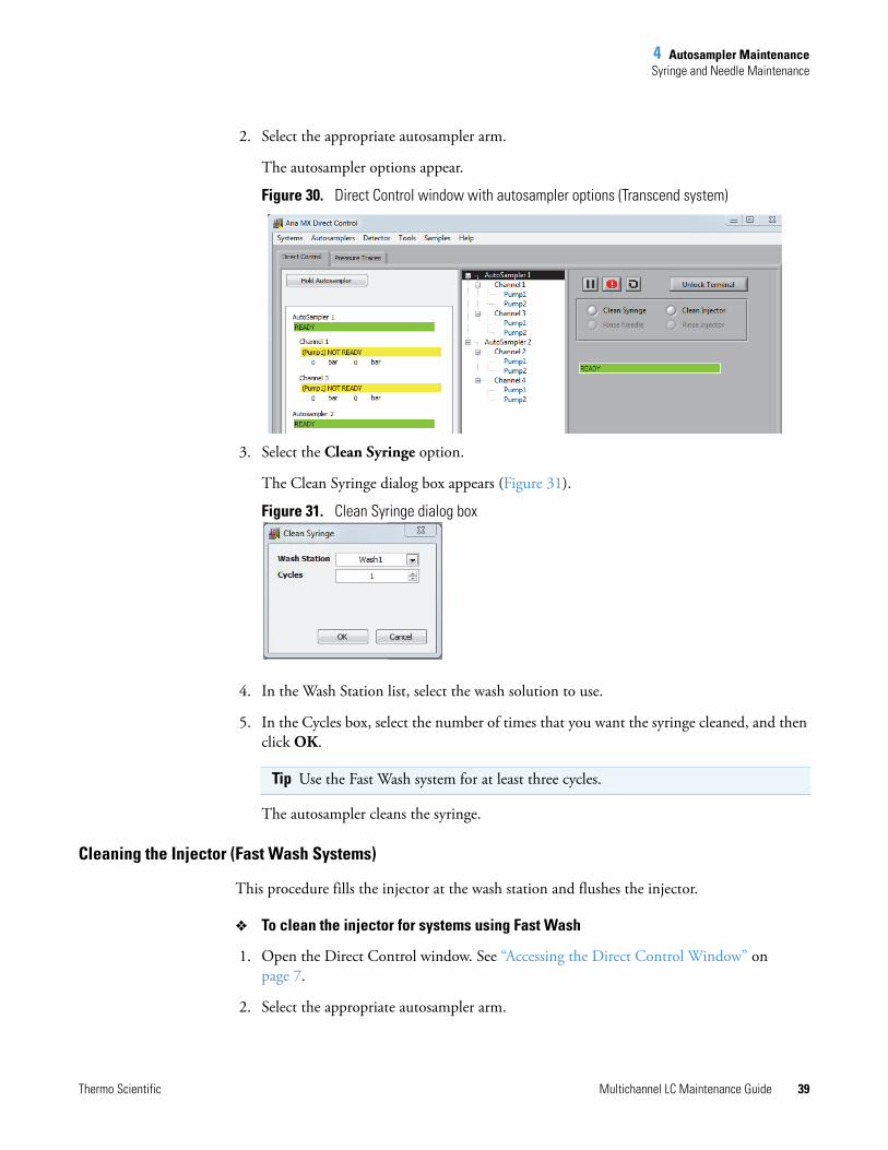
2. Select the appropriate autosampler arm.
The autosampler options appear.
Figure 30. Direct Control window with autosampler options (Transcend system)
3. Select the Clean Syringe option.
The Clean Syringe dialog box appears (Figure 31).
Figure 31. Clean Syringe dialog box
4. In the Wash Station list, select the wash solution to use.
5. In the Cycles box, select the number of times that you want the syringe cleaned, and then click OK.
The autosampler cleans the syringe.
Cleaning the Injector (Fast Wash Systems)
This procedure fills the injector at the wash station and flushes the injector.
To clean the injector for systems using Fast Wash
1. Open the Direct Control window. See “Accessing the Direct Control Window” on page 7.
2. Select the appropriate autosampler arm.
Tip Use the Fast Wash system for at least three cycles.

4 Autosampler MaintenanceSyringe and Needle Maintenance
40 Multichannel LC Maintenance Guide Thermo Scientific
The autosampler options appear.
Figure 32. Direct Control window with autosampler options
3. Select the Clean Injector option.
The Clean Injector dialog box appears (Figure 33).
Figure 33. Clean Injector dialog box
4. From the Wash Station list, select the wash solution to use.
5. From the Injector list, select the injector you want to clean.
6. In the Cycles box, select the number of times that you want to wash the injector, and click OK. Select at least three cycles.
The window closes and the autosampler cleans the injector.
Rinsing the Needle on Systems with a Dynamic Load Wash (DLW)
Use the following procedures to rinse the needle or syringe at the wash station for the specified autosampler model.
To rinse the needle on systems equipped with the Accela Open autosampler
1. Open the Direct Control window. See “Accessing the Direct Control Window” on page 7.
2. Select the appropriate autosampler arm.
The autosampler options appear.

4 Autosampler MaintenanceSyringe and Needle Maintenance
Thermo Scientific Multichannel LC Maintenance Guide 41
3. Select the Rinse Needle option.
The Rinse Needle dialog box opens.
Figure 34. Rinse Needle dialog box (Accela Open autosampler)
4. In the Wash list, select the wash solution to use.
5. In the Injector list, select the injector that will rinse the needle.
6. In the Needle Gap box, leave the value at the default setting, unless a service engineer instructs you to change it.
7. In the Rinse Time box, select the duration of time in seconds to rinse the needle, and then click OK.
To rinse the syringe or needle on systems equipped with the TriPlus autosampler
1. Open the Direct Control window. See “Accessing the Direct Control Window” on page 7.
2. Select the appropriate autosampler arm.
The autosampler options appear.
3. Select the Clean Syringe option.
The Clean Syringe dialog box opens.
Figure 35. Clean Syringe dialog box (TriPlus autosampler)
Tip For optimal cleaning, set the rinse time to a minimum of 10 seconds.

4 Autosampler MaintenanceSyringe and Needle Maintenance
42 Multichannel LC Maintenance Guide Thermo Scientific
4. In the Wash list, select the wash solution to use.
5. In the Cycles box, type the number of rinse cycles that you want, and then click OK.
The TriPlus autosampler arm moves and starts the clean cycle.
Rinsing the Injector on Systems with a DLW or LCMS-P tool
Use the following procedures to rinse an injector at the wash station for the specified autosampler model for systems that are configured with a DLW.
To rinse the injector on systems with a DLW (Accela Open)
1. Open the Direct Control window. See “Accessing the Direct Control Window” on page 7.
2. Select the appropriate autosampler arm.
The autosampler options appear.
Figure 36. Direct Control window with autosampler options (Accela Open)
3. Select the Rinse Injector option.
The Rinse Injector dialog box appears.
Figure 37. Rinse Injector dialog box (Accela Open)
4. From the Wash list, select the wash that will clean the injector.
5. From the Injector list, select the injector to clean.
Tip For optimal cleaning, set the rinse cycles to a minimum of 3 cycles.

4 Autosampler MaintenanceSyringe and Needle Maintenance
Thermo Scientific Multichannel LC Maintenance Guide 43
6. In the Rinse Time box, select the duration of time in seconds to rinse the needle, and then click OK.
The window closes and the autosampler cleans the injector.
To clean the injector on systems with an LCMS-P tool (TriPlus)
1. Open the Direct Control window. See “Accessing the Direct Control Window” on page 7.
2. Choose the appropriate autosampler arm.
The autosampler options appear.
Figure 38. Direct Control window with autosampler options (TriPlus)
3. In the right pane, select the Clean Injector option.
The Clean Injector dialog box appears.
Figure 39. Clean Injector dialog box (TriPlus)
4. From the Injector list, select the injector to clean.
5. From the Wash list, select the wash that will clean the injector.
6. In the Cycles box, type the number of cycles to rinse the needle, and then click OK.
Tip For optimal cleaning, set the rinse time to a minimum of 5 seconds.

4 Autosampler MaintenanceSyringe and Needle Maintenance
44 Multichannel LC Maintenance Guide Thermo Scientific
The window closes and the autosampler starts to clean the injector.
TriPlus Syringe and Needle Replacement
Use the Aria MX Change Tool command to change a TriPlus LCMS-P tool, syringe barrel, or needle. When you run the Change Tool command, the Syringe Exchange wizard appears, which takes you through the step-by-step procedure (see Figure 40).
To change a TriPlus LCP tool, syringe barrel, or needle
1. Open the Aria MX Direct Control Window.
2. From the middle pane, click the autosampler where you want to make the change.
3. In the right pane, select the Change Tool option.
The Syringe Exchange wizard appears (Figure 40).
Tip For optimal cleaning, set the rinse cycles to a minimum of 3 cycles.
CAUTION The autosampler arm moves to perform the following operation.

4 Autosampler MaintenanceDownloading Autosampler Objects to Aria MX (Accela Open)
Thermo Scientific Multichannel LC Maintenance Guide 45
Figure 40. Syringe Exchange wizard from the Direct Control window
4. Follow the on-screen wizard instructions to change the LCP tool, syringe barrel, or needle.
For more information, browse the Autosamplers folder on the Aria MX DVD and refer to the documentation that is located inside the folder corresponding to your autosampler model. For TriPlus replacement parts information, see Appendix A, “Replaceable Parts and Consumables.”
Downloading Autosampler Objects to Aria MX (Accela Open)This procedure sends information from the autosampler firmware to the Aria MX software. Perform this procedure if you have changed any Accela Open autosampler components.
To download objects to the Aria MX application
1. Open the AS Method Editor. Refer to the Aria MX User Guide for details.
2. Choose Tools > Refresh Objects.
The autosampler downloads the information.
Syringe Exchange wizard
4 Autosampler MaintenancePriming the Dynamic Load Wash (DLW) Wash System
46 Multichannel LC Maintenance Guide Thermo Scientific
Priming the Dynamic Load Wash (DLW) Wash System Prime the DLW according to your laboratory’s maintenance schedule by using the Rinse Needle option in the Direct Control window.
To prime the DLW
1. Open the Aria MX Direct Control window (see “Accessing the Direct Control Window” on page 7).
2. Perform the Rinse Needle procedure using Wash 2 and with a rinse time of 10 seconds. See “Rinsing the Needle on Systems with a Dynamic Load Wash (DLW)” on page 40.
3. Perform the procedure using Wash 1 and with a minimum rinse time of 10 seconds. Continue to rinse until there are no visible air bubbles in the wash line.
4. Repeat steps 2 and 3 for the second DLW if you have one installed on your system.
Priming the TriPlus LCMS-P Tool Wash Pumps
To prime the wash pumps for the LCMS-P tool
1. Select the Prime Wash option.
The Prime Wash Pump dialog box appears.
2. In the Wash list, select the wash pump (number) that you want to prime.
3. In the Cycles box, type the number of priming cycles that you want, and then click OK.
The dialog box closes. The selected wash pump starts the priming operation.
To use the TriPlus autosampler handheld controller
Make sure that the TriPlus autosampler is in standby mode and that no samples are pending in the queue.
You can now use the TriPlus handheld controller.
Note The maximum rinse time that you can set is 60 seconds.
Note Thermo Fisher Scientific recommends setting the prime cycle count to 15 to 20 cycles if the system has been inactive for a long period of time. For short periods of inactivity—overnight, for example—3 to 5 prime cycles are sufficient.
Note The autosampler handheld controller is intended for advanced users. Thermo Fisher Scientific recommends that you use the Aria MX interface to perform most of the general and daily tasks.

4 Autosampler MaintenancePriming the TriPlus LCMS-P Tool Wash Pumps
Thermo Scientific Multichannel LC Maintenance Guide 47
For more information, browse the Autosamplers folder on the Aria MX DVD and refer to the documentation inside the folder that corresponds to your autosampler model.
Note If the TriPlus handheld controller indicates that the autosampler is “Busy” without any apparent activity, do the following:
1. Select Autosampler from the Direct Control window’s middle pane.
2. Click the Abort icon, .
3. Perform any necessary TriPlus changes with the handheld controller, and then return to the Direct Control window for any further operations.

4 Autosampler MaintenancePriming the TriPlus LCMS-P Tool Wash Pumps
48 Multichannel LC Maintenance Guide Thermo Scientific
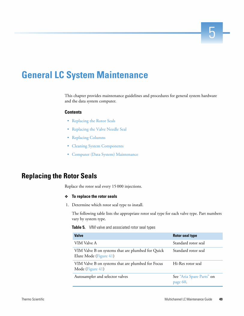
Thermo Scientific Multichannel LC Maintenance Guide 49
5
General LC System Maintenance
This chapter provides maintenance guidelines and procedures for general system hardware and the data system computer.
Contents
• Replacing the Rotor Seals
• Replacing the Valve Needle Seal
• Replacing Columns
• Cleaning System Components
• Computer (Data System) Maintenance
Replacing the Rotor SealsReplace the rotor seal every 15 000 injections.
To replace the rotor seals
1. Determine which rotor seal type to install.
The following table lists the appropriate rotor seal type for each valve type. Part numbers vary by system type.
Table 5. VIM valve and associated rotor seal types
Valve Rotor seal type
VIM Valve A Standard rotor seal
VIM Valve B on systems that are plumbed for Quick Elute Mode (Figure 41)
Standard rotor seal
VIM Valve B on systems that are plumbed for Focus Mode (Figure 41)
Hi-Res rotor seal
Autosampler and selector valves See “Aria Spare Parts” on page 60.
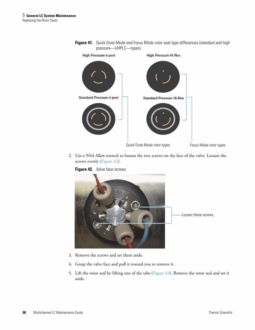
5 General LC System MaintenanceReplacing the Rotor Seals
50 Multichannel LC Maintenance Guide Thermo Scientific
Figure 41. Quick Elute Mode and Focus Mode rotor seal type differences (standard and high pressure—UHPLC—types)
2. Use a 9/64 Allen wrench to loosen the two screws on the face of the valve. Loosen the screws evenly (Figure 42).
Figure 42. Valve face screws
3. Remove the screws and set them aside.
4. Grasp the valve face and pull it toward you to remove it.
5. Lift the rotor seal by lifting one of the tabs (Figure 43). Remove the rotor seal and set it aside.
Quick Elute Mode rotor types Focus Mode rotor types
Loosen these screws.

5 General LC System MaintenanceReplacing the Valve Needle Seal
Thermo Scientific Multichannel LC Maintenance Guide 51
Figure 43. Rotor seal
6. Line up the new rotor seal tabs to the slots on the valve and with the rotor seal grooves facing toward you. The slots are aligned so that the seal can only be installed at the proper orientation.
7. Press the rotor seal into place.
8. Reinstall the valve face so that ports 6 and 1 appear at the top.
9. Partially tighten one screw and then the other. Alternately tighten the screws until both are fully tightened.
10. Prior to running samples, make at least one blank (water) injection on the system.
Replacing the Valve Needle SealReplace the needle seal every 5000 injections.
To replace the needle seal
1. Unscrew the needle guide from the valve (Figure 44).
Rotor seal tab
Rotor seal groove

5 General LC System MaintenanceReplacing Columns
52 Multichannel LC Maintenance Guide Thermo Scientific
Figure 44. Injector valve and needle guide
2. Remove the needle seal from inside the needle guide (Figure 45).
Figure 45. Needle guide and needle seat
3. Install a new needle seat into the needle guide with the metal ferrule pointing away from the needle guide (Figure 45).
4. Screw the needle guide into the valve.
For a standard or DLW syringe, set the needle penetration level. See “Setting the Needle Penetration Level” on page 30.
Replacing Columns It is important to replace analytical or TurboFlow columns within the recommended interval for each type.
In general, consider replacing the two types of columns as follows:
• Replace a TurboFlow column every 300 to 1000 injections. You can replace the column at shorter or longer intervals depending on the samples and methods you run. Follow the recommended installation procedure on the column product insert.
• Replace an analytical column every 2000 injections. You can replace the column at shorter or longer intervals depending on the samples and methods you run. Follow the recommended installation procedure on the column product insert.
5 General LC System MaintenanceReplacing Columns
Thermo Scientific Multichannel LC Maintenance Guide 53
Additionally, view the data from the system pressure traces to determine column conditions. Refer to the Aria MX User Guide for details regarding monitoring the pump pressure.
For more information on replacing each type of column, see the following sections:
• Replacing the TurboFlow Column
• Replacing the Analytical Column
Replacing the TurboFlow Column
Replace the TurboFlow column every 300 to 1000 injections. Use the Maintenance dialog box to track injection numbers. See “Tracking the Number of Injections” on page 9.
CAUTION Replace the column with the column type and size specified in your laboratory’s standard operating procedures. Column types and sizes must be compatible with the method you are running.
CAUTION To keep the new column from drying out, do not remove the end caps from a new column until you are ready to install it onto the system.
CAUTION Column heaters can become extremely hot and, therefore, unsafe to handle. Allow the column and tubing to cool to below 50 °C —about 15 minutes—before handling the column, tubing, and other system components that are near the heater.
CAUTION If you use solvents that emit hazardous vapors, take appropriate chemical and hazardous vapor precautions when you remove the TurboFlow or analytical column from the system. Wear gloves, protective clothing, and eye wear as indicated in your laboratory’s chemical safety operating procedures.

5 General LC System MaintenanceReplacing Columns
54 Multichannel LC Maintenance Guide Thermo Scientific
To replace the TurboFlow column
1. Turn off the column heater and allow the column heater to cool to room temperature.
a. Open the Aria MX Direct Control window.
b. Click a column heater that appears under the appropriate channel name.
c. To turn off the column heater, click the Enable button so that it shows dark green.
d. Repeat step b and step c to turn off the second column heater.
2. When the column heater has cooled, unwrap the column heater from the column.
3. Replace the column as directed in Replacing the Analytical Column.
Replacing the Analytical Column
Replace the analytical column every 2000 injections. Use the Maintenance dialog box to track injection numbers. See “Tracking the Number of Injections” on page 9.
To replace the analytical column
1. Turn off the column heater as follows and allow the column heater to cool to room temperature:
a. Open the Direct Control window.
Note Use only your fingers to manipulate the tubing fittings on Prelude systems. Transcend systems require tools, depending on the procedure.
CAUTION Replace the column with the column type and size specified in your laboratory’s standard operating procedures. Column types and sizes must be compatible with the method you are running.
CAUTION To keep the new column from drying out, do not remove the end caps from a new column until you are ready to install it onto the system.
CAUTION Column heaters can become extremely hot and, therefore, become unsafe to handle. Allow the column and tubing to cool to below 50 °C—about 15 minutes— before handling the column, tubing, and other system components that are near the heater.
CAUTION If you use solvents that emit hazardous vapors, take appropriate chemical and hazardous vapor precautions when you remove the TurboFlow or analytical column from the system. Wear gloves, protective clothing, and eye wear as indicated in your laboratory’s chemical safety operating procedures.

5 General LC System MaintenanceCleaning System Components
Thermo Scientific Multichannel LC Maintenance Guide 55
b. Click a column heater for the appropriate channel.
Figure 46. Direct Control window showing column heater controls
c. Click the Enable button so that it shows dark green.
The column heater is turned off.
d. Repeat step b and step c for the second column heater if applicable.
2. When the column heater has cooled, unwrap the column heater from the column.
3. Replace the column as follows:
a. Loosen the knob on one end of the column until the fitting disengages from the column. Do not use tools on the fittings.
b. Loosen the fitting on the other end of the column while holding onto the column.
c. Remove the column and dispose of the column according to your laboratory’s standard operating procedure.
d. Remove the end cap from one end of the new column and insert the column fitting.
e. Tighten the screw. Avoid overtightening.
f. Remove the end cap from the other end of the column and insert the column fitting.
Cleaning System ComponentsThe following sections provide details on cleaning your system components, which include solvent lines. pumps, and valves.
• Cleaning the Solvent Lines, Pumps, and Valves
• Cleaning the Solvent Lines and Pumps
Note Use only your fingers to manipulate the tubing fittings on Prelude systems. Transcend systems require tools, depending on the procedure.

5 General LC System MaintenanceCleaning System Components
56 Multichannel LC Maintenance Guide Thermo Scientific
Cleaning the Solvent Lines, Pumps, and Valves
If you use buffers with high salt concentrations, the following procedure cleans the lines, pumps, and valves, and helps prevent a salt buildup.
To clean the solvent lines, pumps, and valves
1. Remove all the columns from the system and cap them with plugs.
2. Put low dead volume unions on the system in place of the columns.
3. Remove all the lines from the mobile phase bottles, place them into LC/MS grade deionized water, and do the following:
a. Prime the pumps with water for 5 minutes. See “Priming the LC Pumps for Transcend Systems” on page 12.
b. Verify that the purge valves are closed, if applicable.
c. Precondition the pumps with water for 10 minutes. Refer to the Aria MX User Guide for details.
d. Create and submit a batch that runs five blanks (water) from the same vial.
e. Load a vial of water into the appropriate position on the autosampler and perform the run.
4. Place all the lines into cleaning solvent. See “Preparing the TurboFlow Column Wash Solvent” on page 3. Then do the following:
a. Prime the system for 5 minutes.
b. Precondition the pumps for 10 minutes. Refer to the Aria MX User Guide for details.
c. Run five water blanks from the same vial.
5. Place all the lines into deionized water and do the following:
a. Prime the system for 5 minutes.
b. Precondition the pumps for 10 minutes. Refer to the Aria MX User Guide for details.
c. Create and submit a batch that runs five blanks from the same vial. Then, load a vial of water into the appropriate position on the autosampler and perform the run.
6. Place all the lines into fresh mobile phase solutions and do the following:
a. Prime the system for 5 minutes.
b. Precondition the pumps for 10 minutes. Refer to the Aria MX User Guide for details.
c. Create and submit a batch that runs five blanks (water) from the same vial.
Note Thermo Fisher Scientific recommends that you do not use buffers with high salt concentrations on an LC system connected to a mass spectrometer.

5 General LC System MaintenanceCleaning System Components
Thermo Scientific Multichannel LC Maintenance Guide 57
d. Load a vial of water into the appropriate position on the autosampler and perform the run.
7. Remove the low dead volume unions and install the appropriate columns.
8. Precondition the pumps with mobile phases for 10 minutes to precondition the columns you installed in step 7. Refer to the Aria MX User Guide for details.
Cleaning the Solvent Lines and Pumps
If you use buffers with high salt concentrations, this procedure cleans the lines and helps prevent salt buildup.
To clean the solvent lines and pumps
1. Prime all pumps with mobile phases for 5 minutes.
2. Remove all the lines from the mobile phase bottles and place them into reagent grade deionized water. Prime the pumps with deionized water for 5 minutes.
3. Remove all the lines from the deionized water bottles and place them into cleaning solvent. See “Preparing the TurboFlow Column Wash Solvent” on page 3. Prime the pumps with cleaning solvent for 5 minutes.
4. Remove all the lines from the cleaning solvent bottles and place them into mobile phase bottles. Prime the pumps with mobile phases for 5 minutes.
5. Verify that the purge valves are closed.
Note Thermo Fisher Scientific recommends that you do not use buffers with high salt concentrations on an LC system connected to a mass spectrometer.
Note You can prime multiple pumps at the same time. See “Priming the LC Pumps for Transcend Systems” on page 12.
Note If the cleaning solution is not compatible with the wash solutions, prime the pumps with deionized water before performing step 4.

5 General LC System MaintenanceComputer (Data System) Maintenance
58 Multichannel LC Maintenance Guide Thermo Scientific
Computer (Data System) MaintenanceThe following sections provide recommendations on maintaining your data system to ensure peak performance and uptime.
Periodic Computer System Updates
The Aria MX software runs on the Microsoft™ Windows™ 10 and Windows 7 operating systems. You might need to restart the system periodically to initiate operating system updates and so on. Consider updating your settings when running the LC system. Follow your IT department guidelines regarding any required service and security updates.
Suspending Computer Sleep Mode When Running Aria MX
The Aria MX software will prevent the data system computer from entering sleep mode when it is a configured device in Foundation™ platform.

Thermo Scientific Multichannel LC Maintenance Guide 59
A
Replaceable Parts and Consumables
Aria, Transcend II, Transcend, Prelude SPLC systems, and the TriPlus RSI autosampler occasionally require the replacement of certain parts and consumables. This appendix provides part number lists for common spare parts and system consumables.
Contents
• General Consumables
• Aria Spare Parts
• Transcend II, Transcend UHPLC Spare Parts
• Prelude SPLC Spare Parts
• TriPlus RSI Autosampler Spare Parts
• Chemicals List
General Consumables Table 6 contains part numbers and descriptions of consumable parts for the LC instruments described in this guide. To ensure proper results in servicing the instrument, order only the parts that are listed or their equivalent.
Table 6. Consumable parts for the LC instrument (Sheet 1 of 2)
Description Part number Component
Solvent filter CH-105374 For systems with Agilent™ and Shimadzu™ pumps
PEEK Tubing, 0.005 ID × 0.062 OD × 1.5 m
00109-02-00041 -
One Piece Fingertight PEEK Fitting, 10-32
00109-00314 -
DLW2 stainless steel needle/loop 00950-01-00360 -

A Replaceable Parts and ConsumablesAria Spare Parts
60 Multichannel LC Maintenance Guide Thermo Scientific
Aria Spare Parts
DLW teflon loop with needle adapter
00950-01-00317 -
DLW needle kit, 3-pack 00950-01-00328 -
DLW 100uL glass syringe 00950-01-00325 -
DLW syringe plunger, 10-pack 00950-01-00326 -
Syringes (use X-type for longer life)
100 μL Std bore CH-952489 -
250 μL Std bore CH-952490 -
25 μL Std bore CH-952488 -
100 μL X-Type Wide bore CH-952929 -
100 μL X-Type Std bore CH-952930 -
25 μL X-Type Std bore CH-952931 -
Table 6. Consumable parts for the LC instrument (Sheet 2 of 2)
Description Part number Component
Table 7. Spare parts for the Aria HPLC system (up to 400 bar)
Description Part number Component
Low pressure rotor seal (3 groove)
CH-952356 Can be used with the following valves:
• Injection valve• VIM A valve • VIM B valve (Quick Elute Mode)• VIM bypass valve
Hi-Res rotor seal CH-952357 VIM B valve (Focus Mode)
Injector stator CH-952480 -
6-port stator CH-952679 Can be used with the following valves:
• VIM A valve• VIM B valve• VIM bypass valve
Selector stator (H-Style)
CH-106686 -
Needle seal, 10-pack CH-952451 -
Solvent filter CH-952835 Aria systems with Allegro pumps

A Replaceable Parts and ConsumablesTranscend II, Transcend UHPLC Spare Parts
Thermo Scientific Multichannel LC Maintenance Guide 61
Transcend II, Transcend UHPLC Spare Parts
Prelude SPLC Spare Parts
Table 8. Spare parts for Transcend II and Transcend UHPLC systems (greater than 400 bar)
Description Part number Component
High pressure rotor seal (3 groove)
CH-953197 Can be used with the following valves:
• Injection valve• VIM A valve• VIM B valve (Quick Elute Mode)• VIM bypass valve
High pressure Hi-Res rotor seal
CH-953198 VIM B valve (Focus Mode)
High pressure injector stator (15 PSI)
CH-953295 -
High pressure 6-port stator (15 PSI)
CH-953264 Can be used with the following valves:
• VIM A valve• VIM B valve• VIM bypass valve
Selector rotor seal CH-953396 -
Selector stator (H-Style)
CH-106686 -
Needle seal, 10-pack CH-952451 -
Solvent filter CH-952835 Transcend II systems using UltiMate pumps
Table 9. Spare parts for Prelude SPLC systems
Description Part number
Needle seal, 5-pack 00950-01-00437
Graphite column ferrules, 5-pack 00109-02-00044
Solvent inlet filter, 1/8 inch 00301-01-00036
Corning square solvent bottle, 1 L 00301-01-00032
Bottle cap adapter 00301-01-00065
Accucore™ PFP 50 × 2.1 mm column 17426-052130
TurboFlow Cyclone-P 0.5 × 50 mm column CH-953289

A Replaceable Parts and ConsumablesTriPlus RSI Autosampler Spare Parts
62 Multichannel LC Maintenance Guide Thermo Scientific
TriPlus RSI Autosampler Spare Parts
Chemicals ListThe following chemicals are available from Fisher Scientific.F
Table 10. Spare parts for TriPlus (RSI) autosamplers
Description Part number
Needle seal, 5-pack 00950-01-00437
DLW needle kit, 3-pack 00950-01-00328
Syringe, 100 uL, for the LCMS tool (RSI model) 00950-01-00506
Injector rotor seal (3 groove) 00110-03-00025
Table 11. Chemicals list
Description Part number Size
Ammonium formate in water, 10 mM, with 0.05% formic acid
MB123-1 1 L
Ammonium formate in methanol, 10 mM, with 0.05% formic acid
MB122-1 1 L
45:45:10 isopropanol/acetonitrile/acetone MB124-1 1 L
Acetone A929-1 1 L
Acetonitrile A955-4
A955-1
4 L
1 L
Ammonium formate A11550 4 L
Water W6-4
W6-1
4 L
1 L
Formic acid A117-10X1AMP 10 × 1 mL ampules
Isopropanol A461-1 1 L
Methanol A456-4
A456-1
4 L
1 L