thermo scientific barnstead smart2pure ultrapure water · pdf filepreface ii smart2pure thermo...
TRANSCRIPT

Thermo Scientific Barnstead Smart2Pure Ultrapure water systemOperating Instructions
50148311 Revision B June 2016

© 2016 Thermo Fisher Scientific Inc. All rights reserved.
Thermo Fisher Scientific Inc. provides this document to its customers with a product purchase to use in the product operation. This document is copyright protected and any reproduction of the whole or any part of this document is strictly prohibited, except with the written authorization of Thermo Fisher Scientific Inc.
The contents of this document are subject to change without notice. All technical information in this document is for reference purposes only. System configurations and specifications in this document supersede all previous information received by the purchaser.
This document is not part of any sales contract between Thermo Fisher Scientific Inc. and a purchaser. This document shall in no way govern or modify any Terms and Conditions of Sale, which Terms and Conditions of Sale shall govern all conflicting information between the two documents.
Release history:
For Research Use Only. Not for use in diagnostic procedures.

Thermo Scientific Smart2Pure i
P
Preface
© 2016 Thermo Fisher Scientific Inc. All rights reserved. These operating instructions are protected by copyright. Rights resulting thereof, particularly reprint, photomechanical or digital postprocessing or reproduction, even in part, are only allowed with the written consent of Thermo Electron LED GmbH. This regulation does not apply to reproductions for in-plant use. The contents of this operating instructions manual may change at any time and without any prior notice. In case of conflicting translations into foreign languages the German-language version of these operating instructions shall be binding.
Please read through the information given in these operating instructions on installing and operating the system before you begin installation and use of your water purification system. This is of particular importance, as we, the manufacturer, do not assume any liability for damage due to incorrect operation or use of the system other than the intended use.
Thermo Fisher Scientific Inc. provides this document to its customers with a product purchase to use in the product operation. This document is copyright protected. Any reproduction of the whole or any part of this document is strictly prohibited, except with the written authorization of Thermo Fisher Scientific Inc. The contents of this document are subject to change without notice. All technical information in this document is for reference purposes only. System configurations and specifications in this document supersede all previous information received by the purchaser.
Thermo Fisher Scientific Inc. makes no representations that this document is complete, accurate or error-free and assumes no responsibility and will not be liable for any errors, omissions, damage or loss that might result from any use of this document, even if the information in the document is followed properly.
This document is not part of any sales contract between Thermo Fisher Scientific Inc. and a purchaser. This document shall in no way govern or modify any Terms and Conditions of Sale, which Terms and Conditions of Sale shall govern all conflicting information between the two documents.

Preface
ii Smart2Pure Thermo Scientific
Legal Information
Warranty
Thermo Electron LED GmbH warrants the operational safety and functions of the Thermo Scientific Barnstead Ultrapure Water Systems only under the condition that:
• The system is installed and operated as per the operation manual. Do not use this product for anything other than its intended use.
• the system is not modified,
• only original spare parts and accessories that have been approved by Thermo Electron LED GmbH are used (third-party spares without Thermo Electron LED GmbH approval void the limited warranty),
• inspections and maintenance are performed at the specified intervals,
• an installation verification test is performed on commissioning the system for the first time and repeated after each preventative maintenance and repair activity. The warranty is valid from the date of delivery of the system to the customer.
• The above mentioned warranty conditions are subject to the general terms and conditions of sale, in effect at the time of purchase, which apply as well.
Explanatory notes on the operating instructions
Specifications, terms and pricing are subject to change. Not all products are available in all countries. Please consult your local sales representative for details.
EU Mark of Conformity
CSA - admission
Indicates a situation which, if not avoided, could result in damage to equipment or property.
Indicates a hazardous situation which, if not avoided, could result in death or serious injuries.

Preface
Thermo Scientific Smart2Pure iii
This information is valid for the system that is received. For quick and correct service, please include the following information on all inquiries and replacement parts orders which relate to your system:
• the serial number (located on the right side of the system on the nameplate)
• the catalog number
Indicates a hazardous situation which, if not avoided, will result in death or serious injuries.
Is used for applicational hints and useful information.
Risk of electric shock. Electrical work on the system is only to be carried out by qualified personnel.
Protective conductor connection
Connect the power supply to an electrical socket with a protective connection.
Indicates a situation in which protective gloves or clothing must be worn.
Indicates a situation in which protective goggles must be worn.
Indicates a situation in which breathing protection must be used.

Preface
iv Smart2Pure Thermo Scientific
Standards and directives
The Thermo Scientific Barnstead Ultrapure Water Systems complies with the following standards and directives:
• Low Voltage Directive 2014/35/EC
• EMC Directive 2014/30/EU
• ASTM D1193-6
• RoHs 2011/65/EU
Additionally, the ultrapure water system is in compliance with many other international standards, regulations and directives not listed here. Should you have any questions regarding compliance with national standards, regulations and directives applicable for your country, please contact your Thermo Fisher Scientific sales organization.

Thermo Scientific Smart2Pure v
C
Preface . . . . . . . . . . . . . . . . . . . . . . . . . . . . . . . . . . . . . . . . . . . . . . . . . . . . . . . iLegal Information . . . . . . . . . . . . . . . . . . . . . . . . . . . . . . . . . . . . . . . . . . . . . . . iiWarranty . . . . . . . . . . . . . . . . . . . . . . . . . . . . . . . . . . . . . . . . . . . . . . . . . . . . . iiExplanatory notes on the operating instructions . . . . . . . . . . . . . . . . . . . . . . . . iiStandards and directives . . . . . . . . . . . . . . . . . . . . . . . . . . . . . . . . . . . . . . . . . . iv
Chapter 1 Transport and packaging . . . . . . . . . . . . . . . . . . . . . . . . . . . . . . . . . . . . . . . 1Examination on receipt . . . . . . . . . . . . . . . . . . . . . . . . . . . . . . . . . . . . . . . . . . . 2Complaints . . . . . . . . . . . . . . . . . . . . . . . . . . . . . . . . . . . . . . . . . . . . . . . . . . . . 2Packaging for return shipment. . . . . . . . . . . . . . . . . . . . . . . . . . . . . . . . . . . . . . 2
Chapter 2 Safety Precautions . . . . . . . . . . . . . . . . . . . . . . . . . . . . . . . . . . . . . . . . . . . . . 5
Chapter 3 Extend of delivery . . . . . . . . . . . . . . . . . . . . . . . . . . . . . . . . . . . . . . . . . . . . . 9Extend of delivery Smart2Pure 3/6 . . . . . . . . . . . . . . . . . . . . . . . . . . . . . . . . . 10Extend of Delivery Smart2Pure 12 . . . . . . . . . . . . . . . . . . . . . . . . . . . . . . . . . . 11Available Smart2Pure 3/6 systems . . . . . . . . . . . . . . . . . . . . . . . . . . . . . . . . . . 12Available Smart2Pure 12 systems. . . . . . . . . . . . . . . . . . . . . . . . . . . . . . . . . . . 13Available storage tanks for Smart2Pure 12 systems . . . . . . . . . . . . . . . . . . . . . 13
Chapter 4 Intended Use of the device . . . . . . . . . . . . . . . . . . . . . . . . . . . . . . . . . . . . . . 15Intended Use . . . . . . . . . . . . . . . . . . . . . . . . . . . . . . . . . . . . . . . . . . . . . . . . . . 15Unintended use . . . . . . . . . . . . . . . . . . . . . . . . . . . . . . . . . . . . . . . . . . . . . . . . 15
Chapter 5 Technical Specifications. . . . . . . . . . . . . . . . . . . . . . . . . . . . . . . . . . . . . . . . 17
Chapter 6 The Installation area . . . . . . . . . . . . . . . . . . . . . . . . . . . . . . . . . . . . . . . . . . 23
Chapter 7 Installation . . . . . . . . . . . . . . . . . . . . . . . . . . . . . . . . . . . . . . . . . . . . . . . . . . 25Connections of the Smart2Pure 3/6 system . . . . . . . . . . . . . . . . . . . . . . . . . . . 26Connections of the Smart2Pure 12 system . . . . . . . . . . . . . . . . . . . . . . . . . . . 28Connections of the pure water tank Smart2Pure 12 . . . . . . . . . . . . . . . . . . . . 30Bring your Smart2Pure system into operation . . . . . . . . . . . . . . . . . . . . . . . . . 31Connecting an external tank to the Smart2Pure 12 system . . . . . . . . . . . . . . . 34Illustration of drain . . . . . . . . . . . . . . . . . . . . . . . . . . . . . . . . . . . . . . . . . . . . . 35
Contents

Contents
vi Smart2Pure Thermo Scientific
Attaching the wall holder for 30 or 60L pure water tank . . . . . . . . . . . . . . . . . 36Attaching wall holder for 30L pure water tank. . . . . . . . . . . . . . . . . . . . . . . . . 37Attaching wall holder for 60L pure water tank. . . . . . . . . . . . . . . . . . . . . . . . . 40Wall mounting . . . . . . . . . . . . . . . . . . . . . . . . . . . . . . . . . . . . . . . . . . . . . . . . 42Mounting the power pack (voltage supply) . . . . . . . . . . . . . . . . . . . . . . . . . . . 43Mounting the ball valve to the Smart2Pure system . . . . . . . . . . . . . . . . . . . . . 45
Chapter 8 Flow chart . . . . . . . . . . . . . . . . . . . . . . . . . . . . . . . . . . . . . . . . . . . . . . . . . . . 47
Chapter 9 How the Smart2Pure system functions . . . . . . . . . . . . . . . . . . . . . . . . . . . 49
Chapter 10 Initial start up. . . . . . . . . . . . . . . . . . . . . . . . . . . . . . . . . . . . . . . . . . . . . . . . 51Putting the system into operation . . . . . . . . . . . . . . . . . . . . . . . . . . . . . . . . . . 52Dispensing water from the dispensing valve. . . . . . . . . . . . . . . . . . . . . . . . . . . . 54Venting the 0.2 μm final filter . . . . . . . . . . . . . . . . . . . . . . . . . . . . . . . . . . . . . 54
Chapter 11 Operating Elements . . . . . . . . . . . . . . . . . . . . . . . . . . . . . . . . . . . . . . . . . . . 55
Chapter 12 System control . . . . . . . . . . . . . . . . . . . . . . . . . . . . . . . . . . . . . . . . . . . . . . . 57Menu . . . . . . . . . . . . . . . . . . . . . . . . . . . . . . . . . . . . . . . . . . . . . . . . . . . . . . . 58Mono/dual measurement mode. . . . . . . . . . . . . . . . . . . . . . . . . . . . . . . . . . . . 58Setting the limiting value for conductivity . . . . . . . . . . . . . . . . . . . . . . . . . . . . 59Setting the limiting value for temperature . . . . . . . . . . . . . . . . . . . . . . . . . . . . 60Error message and acoustic error signal . . . . . . . . . . . . . . . . . . . . . . . . . . . . . . 61Communication . . . . . . . . . . . . . . . . . . . . . . . . . . . . . . . . . . . . . . . . . . . . . . . 61Potential-free contact. . . . . . . . . . . . . . . . . . . . . . . . . . . . . . . . . . . . . . . . . . . . 62
Chapter 13 Maintenance . . . . . . . . . . . . . . . . . . . . . . . . . . . . . . . . . . . . . . . . . . . . . . . . . 63Maintenance Intervals . . . . . . . . . . . . . . . . . . . . . . . . . . . . . . . . . . . . . . . . . . . 64Replacing the ultrapure cartridge. . . . . . . . . . . . . . . . . . . . . . . . . . . . . . . . . . . 65Replacing the RO/pretreatment. . . . . . . . . . . . . . . . . . . . . . . . . . . . . . . . . . . . 66Cleaning . . . . . . . . . . . . . . . . . . . . . . . . . . . . . . . . . . . . . . . . . . . . . . . . . . . . . 68Changing the ultrafilter . . . . . . . . . . . . . . . . . . . . . . . . . . . . . . . . . . . . . . . . . . 71UV-reactor assembly . . . . . . . . . . . . . . . . . . . . . . . . . . . . . . . . . . . . . . . . . . . . 73Replacing the UV lamp . . . . . . . . . . . . . . . . . . . . . . . . . . . . . . . . . . . . . . . . . . 74Replacing the 0.2 μm final filter . . . . . . . . . . . . . . . . . . . . . . . . . . . . . . . . . . . 76Autoclaving the 0.2 μm final filter . . . . . . . . . . . . . . . . . . . . . . . . . . . . . . . . . . 76
Chapter 14 Waste disposal . . . . . . . . . . . . . . . . . . . . . . . . . . . . . . . . . . . . . . . . . . . . . . . 77
Chapter 15 Trouble shooting. . . . . . . . . . . . . . . . . . . . . . . . . . . . . . . . . . . . . . . . . . . . . . 79
Chapter 16 Replacement parts . . . . . . . . . . . . . . . . . . . . . . . . . . . . . . . . . . . . . . . . . . . . 81Replacement parts Smart 2Pure 3/6. . . . . . . . . . . . . . . . . . . . . . . . . . . . . . . . . 82Replacement parts Smart2Pure 12. . . . . . . . . . . . . . . . . . . . . . . . . . . . . . . . . . 84Replacement parts pure water tank for Smart2Pure 12 . . . . . . . . . . . . . . . . . . 86

Contents
Thermo Scientific Smart2Pure vii
Chapter 17 Consumables. . . . . . . . . . . . . . . . . . . . . . . . . . . . . . . . . . . . . . . . . . . . . . . . . 87Accessories. . . . . . . . . . . . . . . . . . . . . . . . . . . . . . . . . . . . . . . . . . . . . . . . . . . . 87
Chapter 18 Terminal assignment . . . . . . . . . . . . . . . . . . . . . . . . . . . . . . . . . . . . . . . . . . 89
Chapter 19 Maintenance record . . . . . . . . . . . . . . . . . . . . . . . . . . . . . . . . . . . . . . . . . . . 91
Chapter 20 Contact information Thermo Fisher Scientific . . . . . . . . . . . . . . . . . . . . . 93Index . . . . . . . . . . . . . . . . . . . . . . . . . . . . . . . . . . . . . . . . . . . . . . . . . . . . . . . . 95

Contents
viii Smart2Pure Thermo Scientific

Thermo Scientific Smart2Pure 1
1
Transport and packaging
Content
• “Examination on receipt” on page 5
• “Complaints” on page 5
• “Packaging for return shipment” on page 5
Do not pull the plastic foil over your head. Risk of suffocation.Use the plastic foil only for packaging.

1 Transport and packaging
2 Smart2Pure Thermo Scientific
Ultrapure water systems are carefully inspected and packed prior to shipping, but damage could still possibly occur during transport. Lifting and carrying the Thermo Scientific Barnstead Smart2Pure ultrapure water system, e.g. to the installation location, should be carried out by two people.
Examination on receiptCheck the completeness of the goods received against the packing list.
Complaints
Should damage have occurred to the goods during transport:• Immediately contact your delivery transport agency.• Save the complete packaging, including the cardboard box, for a possible inspection of them
and/or return shipment of the system.
Packaging for return shipmentIf possible, use the original box and packaging material.When these are no longer available, then:
• Protect the system from shock by packing it in bubble wrap and/or packaging foam and a strong cardboard box.
Does the packaging show signs of damage? Inspect the system for damage.
Packaging
System
The time limit for claims is 6 days from the time of receipt of the goods. The right to claim for damages ceases when this time has elapsed.

1 Transport and packaging
Thermo Scientific Smart2Pure 3
• Only a trained person should take the system out of operation.• Prior to send back a operated device, empty the water and dry the system and
take out the cartridges.• pack the ultrapure cartridges into a bubble wrap and/or packaging foam and
take it with in into the package of the Smart2Pure ultrapure water system.

1 Transport and packaging
4 Smart2Pure Thermo Scientific

Thermo Scientific Smart2Pure 5
2
Safety Precautions
• Do not install or operate the system until you have carefully read through these operating instructions and the notes and notices contained therein.
• Lifting and carrying the ultrapure water system, e.g. to the installation location, should be carried out by two people. To do this, lift the system in tandem at the two corner points beneath the bottom plate.
• The CE mark is nullified if you make any structural changes to the system or install products from other manufacturers in/on the system.
• Protect the system from frost. The temperature at the installation area must be between +2 °C and +40 °C.
• Always observe the applicable, pertinent codes and regulations valid at the installation location of the system and follow all applicable accident prevention regulations.
• The feedwater pressure must be at least 0.1 bar and at max. 6 bar or 1.45 to 87 PSI. When the feedwater pressure is higher, install an external pressure reducer.
• A low pressure check valve is recommended to prevent back flow of feedwater from water system.
• A grounded 100-240V, 50/60Hz electrical outlet must be available (see 'Electrical connections' on page 21).
• Access to the power supply cord and plug may never be restricted or obstructed.
• Unplug the system from the power outlet for all maintenance work on the system.
Observe these safety precautions for your own safety!
The Thermo Scientific Barnstead Ultrapure Water Systems are modern water purification system intended solely for the treatment of potable water. The water it produces is not fit for drinking.
Work may only be performed on the system electronics when the system has been switched off and when ESD protection is in place. Only specially trained personnel may work on the system‘s electronics.

2 Safety Precautions
6 Smart2Pure Thermo Scientific
• An atmospherically vented floor drain with a nominal diameter of at least 63 mm (2.48 inch) (DN50 tube) must be present at the installation location. If no drain is provided it is recommended that a water detector be installed for safety reasons (for European specifications only). Failure to provide this will release the manufacturer from liability for any water-induced damage that may result.
• Proceed as follows if the system is not to be operated for an extended period, e.g., over extended weekend, or during a vacation period:
• Switch the system off (unplug the mains plug).
• Close the feedwater inlet (close the feedwater tap).The pump would be damaged if the system were to run without any supply of feedwater. The manufacturer will not accept any liability should this occur.
• The system must be disinfected or rinsed after an extended down time. The cleaning procedure is described under 'Cleaning' on page 68.
• The surface or wall on which the system is to be installed or mounted must have an adequate load-carrying capacity (check the capacity and stability of the wall). The dry weight of the system is given under 'Dimensions and weight Smart2Pure 3/6' on page 18 and 'Dimensions and weight of Smart2Pure12' on page 19. When the internal tank is filled, the system has a weight during operation of approx. 32 kg / 70.55 lbs.
• The surface on which the system is installed must be level and stable not to exceed a maximum of 2% deviation from evenness is recommended.
• When installing the water purification system, always ensure that there is adequate space all around the system (see 'Accessibility to Smart2Pure systems and pure water tank' on page 21) to ensure that ease of use or easy replacement of materials (e.g., filter change, connection) is possible at all times.
• Visually inspect the system at regular intervals. Clean up any water or spills found around the system immediately.
Never look directly into a switched-on UV-lamp, as UV-light endangers eyesight!
To avoid the risk of pinching, crushing, cutting or electrical shock, never perform maintenance on the system without its protective housing, or while it is in operation.Maintenance work on the system may only be performed by trained, authorized specialists.

2 Safety Precautions
Thermo Scientific Smart2Pure 7
.
• To avoid tripping, ensure that the tubings do not lay over the floor.
• Apply the general rules of hygiene for laboratories when working with the system.
• Do not use any oxidative cleaning agents for cleaning the system. These can damage the system.
• Proceed as follows when the system has a defect:
• Switch the system off and unplug the system from power outlet.
• Shut off the feedwater supply.
• Contact your local service organization.
• Wear safety gloves when working with cleaning solutions.• If your skin should come into contact with a chlorine product, rinse it immediately with ample,
fresh water.• The system, or system components, may heat up as a result of a defect. It is recommended to
always wear appropriate safety gloves to prevent skin damage or burns.• Wear safety gloves when changing the UV-lamp, in order to prevent that your skin comes in
contact with the UV-lamp glass.
• Wear safety glasses when working with cleaning solutions.• If your eyes come into contact with a chlorine product, rinse them immediately with ample,
fresh water and contact a physician at once.
• Check the UV-lamp before initial start.
• If the UV-lamp is broken
wear a breathing protector, filter category FFP3 and replace the UV-lamp. For disposal the UV-lamp refer to 'Waste disposal' on page 77.
ventilate the room well.
The Hg content in the UV-lamp is so low so that no damage to the environment can arise.

2 Safety Precautions
8 Smart2Pure Thermo Scientific

Thermo Scientific Smart2Pure 9
3
Extend of delivery
Contents
• "Extend of delivery Smart2Pure 3/6" on page 10
• "Extend of Delivery Smart2Pure 12" on page 11
• "Available Smart2Pure 3/6 systems" on page 12
• "Available storage tanks for Smart2Pure 12 systems" on page 13

3 Extend of delivery
10 Smart2Pure Thermo Scientific
Extend of delivery Smart2Pure 3/6
The following items are included with the Smart2Pure 3/6 pure water system:
1x Smart2Pure 3/6 ultrapure water system: Item No.: 5012xxxx1 x Ultrapure cartridge Item No.: 09.10201x RO/pretreatment cartridge for a 3 l/h system Item No.: 09.2003
for a 6 l/h system Item No.: 09.2006including 1 x assembly kit Item No.: 50129959consisting of:
1 x Final final filter (sterile filter 0.2 μm) Item No.: 09.10031 x Sterile vent air filter Item No.: 22.00911 x Feedwater connecting kit Item No.: 25.00711 x Connectiong tube AD 1/4“ 6 m/8.22 inch Item No.: 18.01371 x Ball valve 1/4“ Item No.: 15.01121 x cleaning adapter Item No.: 501334311 x Table top power pack Item No.: 501495971 x Universal adapter Item No.: 21.10061 x Universal holder Item No.: 21.10071 x Rubber connector to nema plug connector Item No.: 501322001x Rubber connector to british ST plug connector Item No.: 501322031x Rubber connector to euro plug connector Item No.: 501322151 x Plug angle connector 1/4“ Item No.: 14.03611 x T-connector 1/4“ Item No.: 14.03622 x Nylon plugs S6 Item No.: 21.0022 x Countersunk wood screw 4 x 35 Item No.: 21.0069

3 Extend of delivery
Thermo Scientific Smart2Pure 11
Extend of Delivery Smart2Pure 12
The following items are included with the Smart2Pure 12 pure water system:
1 x Smart2Pure 12 ultrapure water system: Item No.: 5012xxxx1 x Ultrapure water tank 30L storage tank or Item No.: 06.5030
60L storage tank Item No.: 06.50601 x Ultrapure cartridge Item No.: 09.10201 x RO/pretreatment cartridge Item No.: 09.2012including 1 x assembly kit Item No.: 50129959consisting of:1 x Final final filter (sterile filter 0.2 μm) Item No.: 09.10031 x Feedwater connecting kit Item No.: 25.00711 x Connectiong tube outer diameter 1/4“ 6 m/8.22 inch Item No.: 18.01371 x Ball valve 1/4“ Item No.: 15.01121 x Cleaning adapter Item No.: 501334311 x Table top power pack Item No.: 501495971 x Universal adapter Item No.: 21.10061 x Universal holder Item No.: 21.10071 x Rubber connector to nema plug connector Item No.: 501322001x Rubber connector to british ST plug connector Item No.: 501322031x Rubber connector to euro plug connector Item No.: 501322151 x Plug angle connector 1/4“ Item No.: 14.03611 x T-connector 1/4“ Item No.: 14.03622 x Nylon plugs S6 Item No.: 21.0022 x Countersunk wood screw 4 x 35 Item No.: 21.0069

3 Extend of delivery
12 Smart2Pure Thermo Scientific
Available Smart2Pure 3/6 systems
Item No.: System
50129869 Smart2pure 3 Standard
50129870 Smart2pure 3 UF
50129872 Smart2pure 3 UV
50129688 Smart2pure 3 UV/UF
50129873 Smart2pure 6 Standard
50129874 Smart2pure 6 UF
50129885 Smart2pure 6 UV
50129887 Smart2pure 6 UV/UF

3 Extend of delivery
Thermo Scientific Smart2Pure 13
Available Smart2Pure 12 systems
Available storage tanks for Smart2Pure 12 systems
Item No.: System
50129888 Smart2pure 12 Standard
50129889 Smart2pure 12 UF
50129890 Smart2pure 12 UV
50129845 Smart2pure 12 UV/UF
Item No.: System Capacity
06.5040 Pure water tank 30 liter
06.5070 Pure water tank 60 liter

3 Extend of delivery
14 Smart2Pure Thermo Scientific

Thermo Scientific Smart2Pure 15
4
Intended Use of the device
Intended Use:
The Thermo Scientific Barnstead Ultrapure Water Systems are laboratory system and is used for treatment of water. The system allows the purification of water into the water categories mentioned in the standards of ASTM 11.01 and ASTM 11.02.
The Thermo Scientific Barnstead Ultrapure Water System are designed to be installed and use in the following application areas:
• Laboratories for cell biological and biotechnological work with the safety levels L1, L2 and L3.
• Medical and microbiological laboratories according to DIN EN 12128.
• Laboratories in the central area of clinics and hospitals.
Unintended use:
The system must not be operated outside of the specifications as described in the operating manual. In particular, the system may not be used for production of drinking water and drugs manufacturing. The system must not be used as a medical device and outside of laboratories.

4 Intended Use of the device
16 Smart2Pure Thermo Scientific
Thermo Scientific Smart2Pure 17
5
Technical Specifications
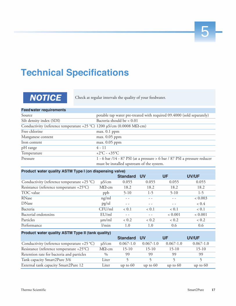
Check at regular intervals the quality of your feedwater.
Feedwater requirementsSource potable tap water pre-treated with required 09.4000 (sold separately)Silt density index (SDI) Bacteria should be < 0.01Conductivity (reference temperature +25 °C) 1200 μS/cm (0.0008 M ·cm)Free chlorine max. 0.1 ppmManganese content max. 0.05 ppmIron content max. 0.05 ppmpH range 4 - 11Temperature +2°C - +35°CPressure 1 - 6 bar /14 - 87 PSI (at a pressure > 6 bar / 87 PSI a pressure reducer
must be installed upstream of the system.
Product water quality ASTM Type I (on dispensing valve) Standard UV UF UV/UF
Conductivity (reference temperature +25 °C) μS/cm 0.055 0.055 0.055 0.055Resistance (reference temperature +25°C) M ·cm 18.2 18.2 18.2 18.2TOC value ppb 5-10 1-5 5-10 1-5RNaseDNase
ng/mlpg/ul
- -- -
- -- -
- - - -
< 0.003< 0.4
Bacteria CFU/ml < 0.1 < 0.1 < 0.1 < 0.1Bacterial endotoxins EU/ml - - - - < 0.001 < 0.001Particles μm/ml < 0.2 < 0.2 < 0.2 < 0.2Performance l/min 1.0 1.0 0.6 0.6
Product water quality ASTM Type II (tank quality) Standard UV UF UV/UF
Conductivity (reference temperature +25 °C) μS/cm 0.067-1.0 0.067-1.0 0.067-1.0 0.067-1.0Resistance (reference temperature +25°C) M ·cm 15-10 15-10 15-10 15-10Retention rate for bacteria and particles % 99 99 99 99Tank capacity Smart2Pure 3/6 Liter 5 5 5 5External tank capacity Smart2Pure 12 Liter up to 60 up to 60 up to 60 up to 60

5 Technical Specifications
18 Smart2Pure Thermo Scientific
The pressure hold valve for concentrate is factory adjusted. Changing of this adjustment causes damage to the reverse osmosis membrane in the RO/pretreatment cartridge. Only specially trained personnel may adjust this pressure. The position of the pressure hold valve for concentrate see chapter Chapter 16, “Replacement parts.”
Permeate and concentrate performance for Smart2PureSystem Permeate ConcentrateAll Smart2Pure 3 l/h 3 50All Smart2Pure 6 l/h 6 55All Smart2Pure 12 l/h 12 60
Dimensions and weight Smart2Pure 3/6Height 545 mm / 21.46 inchWidth 305 mm / 12.01 inchDepth 400 mm / 15.75 inchBase area 277 x 372 mm /10.91 x 14.65 inchWeight including ultrapure cartridge and RO/pretreatment cartridge and full tank
33 kg / 72.77 lbs
545
(21.4
6)
305 (12.01) 400 (15.75)

5 Technical Specifications
Thermo Scientific Smart2Pure 19
Dimensions and weight of Smart2Pure12Height 545 mm / 21.46 inchWidth 305 mm / 12.01 inchDepth 300 mm / 11.81 inchBase area 277 x 372 mm /10.91 x 14.65 inchWeight including ultrapure cartridge and RO/pretreatment cartridge
28 kg / 61.74 lbs
300 (11.81)
545
(21.4
6)
305 (12.01)

5 Technical Specifications
20 Smart2Pure Thermo Scientific
Dimensions and weight 30L and 60L pure water tankSystem 30L pure water tank 60L pure water tankHeight 606 mm / 23.86 inch 920 mm / 36.22 inchWidth Ø 388 / 15.28 inch Ø 384 / 15.12 inchDepth Ø 388/ 15.28 inch Ø 384 / 15.12 inchWeight with full capacity 37,5 kg / 82.57 lbs 71,5 kg / 157.66 lbs
Water connectionsFeedwater tubing Tube 1/4“ outer diameterConcentrate tubing Tube 1/4“ outer diameterTank Flow tubing (only Smart2Pure 12)Tank back flow tubing (only Smart2Pure 12)
Tube 1/4“ outer diameter
Tank overflow tubing (only Smart2Pure 3/6) Tube 1/4“ outer diameterDispenser back flow tubingDispenser flow tubing
Tube 1/4“ outer diameter
Tube jumper Tube 1/4“ outer diameterFront outlet ball valve Tube 1/4“ outer diameter
�388/15.28
606
�384/15.12
920/
36.22

5 Technical Specifications
Thermo Scientific Smart2Pure 21
Electrical connectionsInput voltage AC 100 – 240 VAC, 50 – 60 Hz, 2.0 A maxOutput voltage DC 24 V, 5.0 A maxSystem connection DC 24 V, 120 WSerial Interface RS232Potential free contact maximum 30V, 2AProtection class Class II (external SMPS certified as Class I)
Materials of parts which contact water
Adjustable pressure retaining valve NBR = Acrylnitril Butadien Rubber
Pump head Nylon with glass fibre
UV lamp High-purity synthetic quartz
UV housing Stainless steel
Ultrapure cartridge PP = Polypropylene
UF housing PC = Polycarbonate
Rinsing solenoid valve PA = Polyamide
Dispensing valve PET = Polyethyleneterephthalate
Conductivity measuring cell POM = Polyoxymethylen, stainless steel
Distributor block POM = Polyoxymethylen
Connections POM = Polyoxymethylen
Tubings PE = Polyethylene
O-Rings EPDM = Ethylene propylene diene rubber
Accessibility to Smart2Pure systems and pure water tankSpace on left and right from the side of the system at least 300 mm / 11.81 inchSpace to the back of the system at least 200 mm / 7.87 inchTop space at least 400 mm /15.75 inchSpace to front of system Free accessibility

5 Technical Specifications
22 Smart2Pure Thermo Scientific
Ambient conditionsDuring operation Storage
Operation area Indoor rooms Indoor roomsMaximum altitude above sea level
up to 2000 m up to 2000 m
Temperature range min. +2°C, max +40°C, 80% rel. rH, non-condensing
min. +2 °C, max. +60 °C, 90% rel. rH, non condensing
Line-voltage variation Not more than +/- 10 % of the line voltage -- (not applicable)Transient overvoltages As usually occur in the supply network
(overvoltage category II acc. to IEC 60364-4-443) Note: The rated level of transient overvoltage is the withstand impulse voltage acc. to overvoltage category II of IEC 60364-4-443.
-- (not applicable)
Ventilation requirements no special requirements no special requirementsDegree of pollution 2 2
Airborne sound emissionSound pressure level 49 db(A)

Thermo Scientific Smart2Pure 23
6
The Installation area
Take the following criteria into consideration when selecting the installation area:
Feedwater pressure (potable tap water) not less than 1 bar (14 PSI) and not greater than 6 bar (87 PSI).
• Minimum air temperature +2 °C
• The surface on which the system is installed must be level and stable not to exceed a maximum of 2% deviation from evenness is recommended.
• A smooth wall is required when the system is to be wall-mounted. Check the statics of the wall or standing surface. The standing or wall surface must be strong enough to hold the system. (for system weight, see 'Accessibility to Smart2Pure systems and pure water tank' on page 21).
• An atmospherically floor drain with an outside diameter of 63 mm or 2.48 inch (DN 50 tube) shall be provided.
• Unobstructed draining of the rinsing water to the drain must be ensured.When no floor drain is available, install a water watcher to protect against water damage (available only for Europe).
• A check valve is recommended in the feedwater line to prevent back flow of feedwater from the water system.
The operator is obliged to ensure, that the installation of the water purification unit and its operation are carried out in compliance with all national and international guidelines, applicable and valid for the place of installation.If necessary, measures to protect the drinking water have to be taken by installing appropriate components.
The feedwater pressure must not be allowed to go above 6 bar. Install an additional pressure reducer when the feedwater pressure is higher.
Free gravity flow to drain must be ensured.

6 The Installation area
24 Smart2Pure Thermo Scientific
• An electric socket with protective connection must be available for connection of the system to the voltage supply.(see 'Electrical connections' on page 21)
• Ample working space must be provided around the system for easy and pleasant replacement of wear and replacement parts and for ease of operation (see 'Accessibility to Smart2Pure systems and pure water tank' on page 21).
• Easy access for operation and control of the system.

Thermo Scientific Smart2Pure 25
7
Installation
Content
• “Connections of the Smart2Pure 3/6 system” on page 26
• “Connections of the Smart2Pure 12 system” on page 28
• “Connections of the pure water tank Smart2Pure 12” on page 30
• “Bring your Smart2Pure system into operation” on page 31
• “Connecting an external tank to the Smart2Pure 12 system” on page 34
• “Illustration of drain” on page 35
• “Attaching the wall holder for 30 or 60L pure water tank” on page 36
• “Attaching wall holder for 30L pure water tank” on page 37
• “Attaching wall holder for 60L pure water tank” on page 40
• “Wall mounting” on page 42
• “Mounting the power pack (voltage supply)” on page 43

7 Installation
26 Smart2Pure Thermo Scientific
Connections of the Smart2Pure 3/6 system
678
11
10 9
5
4
3
2
1
12

7 Installation
Thermo Scientific Smart2Pure 27
1. Tank overflow connector for outer diameter 1/4“ tube2. Feedwater connector for outer diameter 1/4“ tube3. Concentrate connector for outer diameter 1/4“ tube4. Dispenser back flow connector for outer diameter 1/4“ tube for additional hand dispenser5. Dispenser flow connector for outer diameter 1/4“ tube for additional hand dispenser6. Connector potential free contact 5 pins7. Power supply connector 24 V DC8. RS232 printer connection9. 1/4“ thread connector for 0.2 μm final filter
10. Quick connectors for RO/pretreatment cartridge11. Quick connectors for ultrapure cartridge12. 1/4 thread connector for sterile vent filter
When you are remove the tube jumper between Pos. 4 and Pos. 5, you have the possibility to connect additionally the accessory hand dispenser, Item No.: 50138221(purchased separately). This hand dispenser comes with an installation guide.

7 InstallationConnections of the Smart2Pure 12 system
28 Smart2Pure Thermo Scientific
Connections of the Smart2Pure 12 system
1
12
11
4
10
7
3
8
9
6
5
2

7 InstallationConnections of the Smart2Pure 12 system
Thermo Scientific Smart2Pure 29
1. 1/4“ thread connector for final filter2. Tank back flow connector for outer diameter1/4“ tube3. Tank flow connector for outer diameter 1/4“ tube4. Concentrate connector for outer diameter 1/4“ tube5. Feedwater connector for outer diameter 1/4“ tube6. Dispenser back flow connector outer diameter 1/4“ tube for additional hand dispenser7. Dispenser flow connector outer diameter 1/4“ tube for additional hand dispenser8. Optional printer connector9. Power supply connector 24V DC
10. Level control connector for external pure water tank11. Quick connectors for RO/pretreatment cartridge12. Quick connectors for ultrapure cartridge
When you remove the tube jumper between Pos. 6 and Pos. 7, you have the possibility to connect additionally the accessory hand dispenser, Item No.: 50138221(purchased separately). This hand dispenser comes with an installation guide.

7 InstallationConnections of the Smart2Pure 12 system
30 Smart2Pure Thermo Scientific
Connections of the pure water tank Smart2Pure 12
13. Tank flow connector for outer diameter 1/4“ tube14. Tank back flow connector for outer diameter 1/4“ tube15. Level control connector16. Connector for optional sterile overflow17. Connector for optional sterile vent filter
16
16
14
15
13
14
15
13
30L pure water tank
60L pure water tank 17
17

7 InstallationConnections of the Smart2Pure 12 system
Thermo Scientific Smart2Pure 31
Bring your Smart2Pure system into operation
• After Installation all tubings have to be checked for their correct position on the systems panel and that is no leakage after open the feedwater supply.
• 09.4000 is a required pre-filter system (see “Feedwater requirements” on page 17)
• To avoid tripping, ensure that the tubings and wires do not lay over the floor.
Step Action Figure
1 Place the Smart2Pure system at the desired location (on the workbench, under the workbench, or wall-mount). A wall attachment kit is available for wall-mounting (purchasing separately).
See Section “Wall mounting” on page 42.
2 Remove the cover from the ultrapure cartridge by pressing the snapper and pull the cover off towards the front.
3 a. Locate the ultrapure cartridge.b. Place the ultrapure cartridge in the rear section
of the system and insert the two quick connectors into the ultrapure cartridge. When you hear an audible click you can be sure that the quick connectors have been inserted correctly.
The quick connectors are attached to the system in such a manner so as to prevent installing the ultrapure cartridge incorrectly.
Snapper
Cover
Ultrapurecartridge
b.) Quick connectors

7 InstallationConnections of the Smart2Pure 12 system
32 Smart2Pure Thermo Scientific
4 a. Locate the RO/pretreatment cartridge.b. Place the RO/pretreatment cartridge in the
front part of the system and insert the three quick connectors into the RO/pretreatment cartridge. When you hear an audible click you can be sure that the quick connectors have been inserted correctly.
The quick connectors are attached to the system in such a manner so it is to prevent installing the RO/pretreatment cartridge incorrectly.
5 a. Use the R3/4“ feedwater connecting kit, supplied with the system, to connect the Smart2Pure system with the feedwater tap. Therefore push the R3/4“ union nut over the outer diameter 1/4“ tube und push in the tube into the fitting and then connect the open end of the outer diameter 1/4“ tube to the feedwater connection of the Smart2Pure panel.
b. After this screw in the R3/4“ union nut with the dirt screen onto the feedwater tap.
Step Action Figure
b)
RO/pretreatment cartridge
Quick connectors
a) 3/4“ Union nut
Outer diameter 1/4“ tube
Dirt screen
Fitting
Feedwater connection Smart2pure 3/6
Feedwater connection Smart2pure 12

7 InstallationConnections of the Smart2Pure 12 system
Thermo Scientific Smart2Pure 33
6 a. Attach on the Snart2Pure 3/6 side panel one piece of outer diameter 1/4“ tubing to the concentrate and a second one to the tank overflow outlet. (see “Connections of the Smart2Pure 3/6 system” on page 26)
b. Route both AD 1/4“ tubes with a free gravity fall to the drain. (see “Illustration of drain” on page 35)
7
If you are using a Smart2Pure 12 system plug in the outer diameter 1/4“ tube into the concentrate connector of the Smart2Pure 12 panel. (see“Connections of the Smart2Pure 12 system” on page 28). Route the outer diameter 1/4“ tube with a free gravity fall to the drain.(see “Illustration of drain” on page 35)
6 Connect the power to the system (see “Mounting the power pack (voltage supply)” on page 43).
7
Before screw in the 0.2 μm final filter onto the 1/4“ thread dispensing valve outlet, wait until the tank have the maximum capacity and leave approx 2-run 3 liters pure water from the dispensing valve.
8 Open the feedwater tap and check that there is no leakage on the connectors and tubes.
Step Action Figure
a) Outer diameter 1/4“ tube
Outer diameter 1/4“ tube
0.2 μm final filter
1/4“ thread

7 InstallationConnections of the Smart2Pure 12 system
34 Smart2Pure Thermo Scientific
Connecting an external tank to the Smart2Pure 12 system
• The external pure water tanks are supplied only with the Smart2Pure 12 system.• The external pure water tanks are available in two different sizes:
• 06.5040 pure water tank 30L• 06.5070 pure water tank 60L
• All connectors for connecting the 30L or 60 L pure water tank to the Smart2Pure 12 system have the same position.
• If you ordered the sterile overflow for pure water tanks, connect the sterile overflow as described in the separate installation guide. If not use a AD 8mm/ 0.31 inch tube to connect the tank overflow to drain as described in this chapter.
• A tank vent filter has to be ordered separately (see “Accessories” on page 87).
Step Action Figure
1 Place the external 30L or 60L pure water tank in the direct vicinity of the Smart2Pure 12 system.
2 Use the AD 1/4“ tube to connect the tank back flow connector on the pure water tank with the tank back flow connector on the Smart2Pure 12 panel.
3 Plug in the AD 1/4“ tube to connect the tank flow connector on the pure water tank to the tank flow connector on the Smart2Pure 12 panel.
Tank back flow connectionSmart2pure 12
Tank back flow connection tank
Tank flow connectionSmart2pure 12
Tank flow connection tank

7 InstallationConnections of the Smart2Pure 12 system
Thermo Scientific Smart2Pure 35
Illustration of drain
4 Locate the cable for level control on the pure water tank and take it into the level control connector of the Smart2Pure 12 panel.
5 Use a AD 8mm/ 0.31 inch tube to connect the tank overflow fitting connector with the drain. Route the AD 8mm/ 0.31 inch tube with a free gravity fall to the drain. (see “Illustration of drain” on page 35)
6 Open the feedwater tap and check that there is no leakage on the connectors and tubes.
Step Action Figure
Level control cable
Level control connection system panel
Tank
Tank overflow fitting
AD 8mm/ 0.31 inch tube
Illustration of drain siphon for inserting the rinsing water and concentrate outlet tube.
Shorten the rinsing water and concentrate outlet tube to the required length and route it to an atmospherically vented drain.The tubes that run from the Smart2Pure system and the external tank to the drain must be routed with a downward slope and without any kinks or restrictions, as this would result in backing up of the draining water.If a standard drain siphon is in place, the ends of the tubes must be located at least 20 mm/ 0.75 inch above the drain. Attach the tubes in such a manner that they remain in their position.
Minimum distance20 mm/0.75 inch
Overflow tube
Rinse water tubing
Drain

7 InstallationConnections of the Smart2Pure 12 system
36 Smart2Pure Thermo Scientific
Attaching the wall holder for 30 or 60L pure water tank
• Additional for the 30L or 60L pure water tanks, you have the possibility to attach a wall holder for the pure water tanks (purchasing separately).
• You need for 30L pure water tank the wall holder, Item No.: 06.5015• For 60L pure water tank you need the wall holder, Item No.: 06.5016• The wall on which the pure water tank is to be installed or mounted must have
an adequate load-carrying capacity (check the capacity and stability of the wall. Weight and dimensions for pure water tanks see “Dimensions and weight 30L and 60L pure water tank” on page 20).
• Lifting and carried out only the 30L or 60L tank by two person.• Do not lift up the 30L or 60L tank with full water capacity. Risk of ergonomic
postural deformities.

7 InstallationConnections of the Smart2Pure 12 system
Thermo Scientific Smart2Pure 37
Attaching wall holder for 30L pure water tankThe extend of the delivery from the wall holder for 30L pure water tanks, includes two holder parts:
• one bottom part wall holder with assembly material and• one upper part holder with assembly material.
Step Action Figure
1 Hold the wall holder bottom part at the desired position on the wall and mark the four boreholes for fixing the wall holder. Then use a 8 mm or 0.31 inch twist drill to make the holes and put in the four S8 plugs which are supplied with the wall holder.
2 Attach the wall holder bottom part to the wall by screwing in the four supplied screws with a philips screw driver into the wall where you put in the plugs before.
3 Place the 30L pure water tank onto the mounted wall holder bottom part with two people and then screw in the four supplied M8 hexagon nuts onto the threaded bolts from the wall holder bottom part. (see pictures next side)
Mark up herethe positionfor boreholes
Wall Wall holderbottom part
Screws
Wall Wall holderbottom part

7 InstallationConnections of the Smart2Pure 12 system
38 Smart2Pure Thermo Scientific
Openings for screw onthe hexagon nuts ontothe wall holder bottompart.
Wall holderbottom part
Hexagon nuts
Threaded bolts
Threaded bolts
Wall holderbottom part

7 InstallationConnections of the Smart2Pure 12 system
Thermo Scientific Smart2Pure 39
Step Action Figure
4 a. Unscrew the lid off the 30L pure water tank.
b. Hold the wall holder upper part at the desired position on the wall and mark the two boreholes for fixing the wall holder upper part. Then use a 8 mm or 0.31 inch twist drill to make the holes and put in the four S8 plugs which are supplied with the wall holder.
To prevent contamination of the 30L pure water tank when the lid is unscrew and mounting works, screw on the lid after you have placed the wall holder upper part on the pure water tank as described above.
5 Screw in the two screws with a Phillips screw driver into the wall where you have put in the plugs before.
6 After mounting the complete wall holder connect the tubing and level control cable as described at chapter “Connecting an external tank to the Smart2Pure 12 system” on page 34.
Mark up herethe positionfor boreholes
Wall holderupper part
b.)
Screws
Wall holderupper part

7 InstallationConnections of the Smart2Pure 12 system
40 Smart2Pure Thermo Scientific
Attaching wall holder for 60L pure water tank
Step Action Figure
1 Locate the two metal brackets and baseplate and screw in as shown in the diagram the six countersunk screws and hexagon nuts supplied with the brackets.
2 Hold the wall holder at the desired position on the wall and mark the six boreholes for fixing the wall holder. Then use a 8 mm or 0.31 inch twist drill to make the holes and put in the six S8 plugs which are supplied with the wall holder.
Mark up here theposition for bore-holes
Wall

7 InstallationConnections of the Smart2Pure 12 system
Thermo Scientific Smart2Pure 41
Step Action Figure
3 Attach the wall holder to the wall by screwing in the six supplied countersunk screws with a Phillips screw driver.
4 Place the 60L pure water tank with two people on the wall holder and repeat the steps 4, 5 and 6 in section “Attaching wall holder for 30L pure water tank” on page 37.
Screws
Wall

7 InstallationConnections of the Smart2Pure 12 system
42 Smart2Pure Thermo Scientific
Wall mounting
You can also mount your Smart2Pure 3/6 or Smart2Pure 12 system on the wall. To do this, use the wall-mounting fixture included in the accessories (purchased separately Item No.: 09.2212). Before you begin mounting the system on the wall you must check the strength of the wall to ensure that it is suitable for supporting the system (see “Dimensions and weight Smart2Pure 3/6” on page 18 and “Dimensions and weight of Smart2Pure12” on page 19 for the system). The screws and anchors supplied with the wall-mounting brackets are only suitable for attaching the wall-mounting brackets to a concrete wall or a solid (masonry) wall.
Step Action Figure
1 Use the wall-mounting brackets to mark the anchoring points with a pen on the wall at the location where the holes are to be drilled for the wall-mounting bracket.Use an 8 mm/ 0.31 inch drill bit to drill the holes.
See figure below.
2 Insert the three S8 Nylon anchors into the holes and then use the three wood screws to firmly screw the wall-mounting brackets into place.
3 Lift the system and hang the back of it on the wall-mounting brackets.
Always lift and carry the system in tandem (two people), never alone. Lift the system at the two bottom corners.
mm/ 7.48 inch
mm/ 3.74 inch
7 InstallationConnections of the Smart2Pure 12 system
Thermo Scientific Smart2Pure 43
Mounting the power pack (voltage supply)
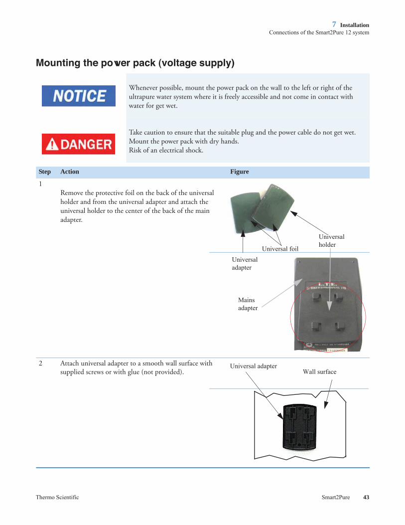
Whenever possible, mount the power pack on the wall to the left or right of the ultrapure water system where it is freely accessible and not come in contact with water for get wet.
Take caution to ensure that the suitable plug and the power cable do not get wet. Mount the power pack with dry hands.Risk of an electrical shock.
Step Action Figure
1Remove the protective foil on the back of the universal holder and from the universal adapter and attach the universal holder to the center of the back of the main adapter.
2 Attach universal adapter to a smooth wall surface with supplied screws or with glue (not provided).
Universaladapter
UniversalholderUniversal foil
Mainsadapter
Universal adapterWall surface

7 InstallationConnections of the Smart2Pure 12 system
44 Smart2Pure Thermo Scientific
3 a. Take the power supply unit and press it with the attached universal holder onto the wall and then slide it down (see red arrows).
b. Plug the power cable into the power supply unit.
Do not bring the power pack in contact with water. Risk of an electrical shock..
The removable power cable must always face downward when the power supply unit has been mounted.
5 Now, connect the power supply unit to the 'Power supply' connection on the right side of the Smart2Pure 3/6 or Smart2Pure 12 system. Next plug the power supply to a grounded 100 - 240V, 50/60 Hz power outlet.
As soon as connect the power supply unit to the power supply connection of the system, the display from the display control is on. After 5 minutes the system is going to be begin with producing pure water.
6 The system is now ready for work.
Step Action Figure
Power supply unitwith support
Universal adapter
Mains adapterPower cable
Power supplyconnection on the system

7 InstallationConnections of the Smart2Pure 12 system
Thermo Scientific Smart2Pure 45
Mounting the ball valve to the Smart2Pure system
Delivered with the assembly kit is a ball valve with a t-connector to have the opportunity to dispensed pure water ASTM Type II quality from the internal or external tank from the Smart2Pure system.
Proceed as follows to do this action.
Step Action Figure
1 Switch the system off. (unplug the main power supply)
2 a. Locate the ball valve, the t-adapter and the outer diameter 1/4“ tube.
b. Remove the tube jumper from the connection panel of the system.
c. Cut from the outer diameter 1/4“ tube two tubes with a length of 80 mm/ 3.2 inch and attach the tubes into the t-adapter and the connection panel. Attach the ball valve with a third outer diameter 1/4“ tube to the t-adapter.
d. Additionally attach a fourth outer diameter 1/4“tube to the other connection of the ball valve.
You can choose the length of the outer diameter 1/4“ tubes beginning from the t-adapter for the ball valve by yourself.
3 Switch the system on. (Connect main power supply)
Tube jumper
Dispenserflow
Dispenser back flow
Connection panel Outer dia-meter 1/4“tube
T-adapter
Ball valve
Outer dia-meter 1/4“tube
b.)
c.)
d.)
Ball valve
Outer dia-meter 1/4“tube
Closed position off ball valve

7 InstallationConnections of the Smart2Pure 12 system
46 Smart2Pure Thermo Scientific

Thermo Scientific Smart2Pure 47
8
Flow chart
The following flow chart describes the Smart2Pure Systems with full equipment (ultrafilter, UV-lamp). Depending on your Smart2Pure system configuration the UV-lamp or ultrafilter are inapplicable. The flow chart direction remains as described in the flow diagram.
Booster pump
RO membranewith integrated pretreatment
Recirculationpump
UV lamp
Ultrapure polishercartridge
Ultrafilter
Finalconductivity
cell with temperature
compensation
Sterile vent filter
ASTM Type 1 system
dispenserwith 0.2 μm
filter
ASTM Type 2 system port
Pure water
Pure water
Ultrapure water
Storage reservoir: Internal for 3 and 6L/h versions. External for 12L/h versions
Tap water
Drain
Purification flow Recirculation flow Waste water

8 Flow chart
48 Smart2Pure Thermo Scientific

Thermo Scientific Smart2Pure 49
9
How the Smart2Pure system functions
When the system is in operation, tap water with a maximum pressure of 6 bar flows into the system and is pumped by pressure booster pump 1 through the RO/pretreatment cartridge. The RO/pretreatment cartridge splits the feedwater by reverse osmosis technology in “permeate and “concentrate“ water flow. The concentrate water flows to drain.The permeate of the reverse osmosis membrane flows into the internal 5L tank or by Smart2 Pure 12 systems into the external pure water tank. If the internal or external pure water tank is filled with maximum capacity with water of ASTM Type II, the feedwater solenoid valve is closed by a level switch and prevents that no more water flows into the system.
After open the dispensing valve the pure water from the tank flows through the UV bulb (only systems with UV), ultrapure cartridge and the ultrafilter (only systems with UF). ASTM Type I water can be dispensed through the 0.2 μm final filter on dispensing valve and ASTM Type II water when you have connect the accessory hand dispenser on the connection panel of the system.
The water in the internal or external tank is recirculated at regular intervals through the pressure booster pump 2 to ensure the constant quality of pure water ASTM Type II. A level switch monitors the water level inside the tank.
ASTM Type II water can be dispensed from the side outlets of internal tank from the connection panel or from the front valve of the external tank.

9 How the Smart2Pure system functions
50 Smart2Pure Thermo Scientific

Thermo Scientific Smart2Pure 51
10
Initial start up
Contents
• “Putting the system into operation” on page 52
• “Dispensing water from the dispensing valve” on page 54
• “Venting the 0.2 μm final filter” on page 54

10 Initial start up
52 Smart2Pure Thermo Scientific
Putting the system into operation
1. Concentrate connector for outer diameter 1/4“ tube2. Feedwater connector for outer diameter 1/4“ tube3. Tank overflow connector for outer diameter 1/4“ tube
4. Tank back flow connector for outer diameter 1/4“ tube5. Tank flow connector for outer diameter 1/4“ tube6. Concentrate connector for outer diameter 1/4“ tube7. Feedwater connector for outer diameter 1/4“ tube
The system must warmed up or cooled down to room temperature before being put into operation.
Check that all connections have been made as described in Chapter 7“Installation” on page 25 or shown in the bottom diagram.
Connections Smart2Pure 3/6
Connections Smart2Pure 12
1 2 3
54
6 7

10 Initial start up
Thermo Scientific Smart2Pure 53
• Put in the voltage supply from the power pack into the power supply from the system on the connection panel.
• Wait until the tank filling has been completed. This could take approx. 1.5 to 3 hours with a Smart2Pure 3/6 system. With a Smart2Pure 12 system this could take up to 2.5 hours to fill a 30L tank and about 5 hours to fill a 60L tank. Discard the content of first tank filling.
• Before screw in the sterile filter onto the dispensing valve outlet, wait until the tank have the maximum capacity and leave approx 2-run 3 liters pure water from the dispensing valve.
• Screw in the sterile filter.
• After connecting the power supply into the system, a brief self test is starting for approx 5 minutes. After the brief self test the system begins to produce pure and ultrapure water.
• If the tank content of the Smart2Pure 3/6 system is empty it is possible that air is coming from the tank into the ultrafilter (only systems with ultrafilter). Thereby you can not dispense water from the sampling tap on the system. Proceed as follows in such a case:
• unplug the main plug and wait 5 seconds before you put the main plug back.
• Wait approx 10-15 minutes before you start with dispensing water from the sampling tap.

10 Initial start up
54 Smart2Pure Thermo Scientific
Dispensing water from the dispensing valve
Venting the 0.2 m final filter
Step Action Figure
1 Turn knob counter clock wise to dispense water.
Water flow out of unit and can be adjusted with turning the knob. Turn the knob clockwise to slow down or stop water flow.
CAUTION Do not over tighten knob once flow stops, doing so could damage dispensing valve.
Knob
Counter clock wise to dispense water
Step Action Figure
1 The first time you dispense pure water at the main dispenser through the 0.2 μm final filter, open the white knurled screw.
2 Do not close the knurled screw until pure water runs out of the opening at the knurled screw continuously. Rinse about 500 ml of water through the final filter.
0.2 μm final filter
Knurled screw

Thermo Scientific Smart2Pure 55
11
Operating Elements
A =Display shows the actual value of final product water resistivity/ conductivity and temperature. If the measurement range end value is exceeded (>199 μS/cm or >0.005 M ·cm ), then ÷ 200 is shown in the display.
B = Second line shows the currently running measurement mode in μS/cm, M ·cm and C°.
C = Third line shows the “Limit value Cond.“, “Temp.“and “Status Sensor“. The “Limit value Cond.“ LED‘s will report any value, out of its limit, immediately. Also the calling up of submenus for limit settings is indicated. The “Status Sensor“ LED shows any error at the conductivity and temperature measuring cell.
D = Menu button: switches the Menu to the next submenu.
E = Down button: decreases adjustable values.
F = up/Quit button: increases adjustable values, quits acoustic alarms.
G = Enter button: confirms changes, allows to adjust the cursor.
18.2A
B
C
D
E
F
G

11 Operating Elements
56 Smart2Pure Thermo Scientific

Thermo Scientific Smart2Pure 57
12
System control
Contents
• “Menu” on page 58
• “Mono/dual measurement mode” on page 58
• “Setting the limiting value for conductivity” on page 59
• “Setting the limiting value for temperature” on page 60
• “Error message and acoustic error signal” on page 61
• “Communication” on page 61
• “Potential-free contact” on page 62

12 System control
58 Smart2Pure Thermo Scientific
Menu
The menu consists of three sub-points:1. Switching to dual mode together with selection of the measurement unit for the
conductivity measurement.2. Setting the product water conductivity limit value.3. Setting the temperature limiting value.
Mono/dual measurement mode
Mono measurement mode: • In this mode only the conductivity is displayed. The temperature can be read when
the “Enter“ button is pressed.Dual measurement mode:
• In this mode, temperature and conductivity are shown alternating in a 2-second tact. The LED for the unit switches with the display.
This following combinations are possible in the Mono/dual measurement mode:• adjusted resistance value M ·cm: “c“ and “ct“• adjusted resistance value μS/cm: “c“ and “ct“
Step Action Picture
1 Press the „“Menu“ button once then the display shows you the last adjustment measurement mode (green LED lights up). The first line shows the selected unit of measurement resistance value (factory adjustments in M ·cm).
2 Use the “up/Quit“ and “down“ button to choose the resistance value for measuring mode (μS/cm or M ·cm) and than choose the mono measurement mode “c“ or dual measurement mode “ct“.
18.2
First line
Display
μS/cm M ·cm °C
Display shows
or
or cct
Display shows

12 System control
Thermo Scientific Smart2Pure 59
Setting the limiting value for conductivity
• The limiting value can only be set in μS/cm and is factory adjusted to a value of 0.1 μS/cm.
• Setting range: 0.055 - 30 μS/cm, basic setting: 0.1 μS/cm
Step Action Picture
1 Press the “Menu“ button twice to enable the limiting value for the conductivity to be set (red LED lights up).
2 Use the “up/quit“ and “down“ button to increase or reduce the value. With the “Enter“ button you switch to the next digit. After finishing adjustment press “Enter“ to confirm the value.
3 Press the “Menu“ button twice to return to the operating mode.
Display shows
Limit value Cond. Temp. Status Sensor
Second line
Display 0.10
or Display shows
0.10
0.10
Display shows

12 System control
60 Smart2Pure Thermo Scientific
Setting the limiting value for temperature
• The limiting value is factory adjusted to a value of +35°C.• Setting range: 10°C - 40°C, basic setting: 35°C
Step Action Picture
1 Press the “Menu“ button three times to enable the limiting value for the temperature to be set (red LED lights up).
2 Use the “up/quit“ and “down“ button to increase or reduce the value. With the “Enter“ button you switch to the next digit. After finishing adjustment press “Enter“ to confirm the value.
3 Press the „“Menu“ button once to return to the operating mode.
Displayshows
Limit value Cond. Temp. Status Sensor
Second line
Display 35°C
or Display shows
35°C
35°C
Display shows

12 System control
Thermo Scientific Smart2Pure 61
Error message and acoustic error signal
Communication
A printer can be connected to the RS232 interface for print out of measured values. The values of the conductivity or temperature are given out at the serial interface seperated by a comma. Automatically the conductivity is scaled to three significant places. Output is made 1x per hour.When the system is in operation mode , a press on the „“down“ button triggers a measured value output at the serial interface.
Print out example: 18.2 M ·cm, 23.4°C
• If the limiting value of the conductivity or temperature are reached, in the display shows “ - - “ or “÷ 200“, the red LED in the second line is lighting up and additionally after approx. 5 minutes an acoustic signal will sound.
Error Lights up LED in second line and acoustic signal
Limiting value of conductivity is reached
Limiting value of temperature is reached
Limiting value of conductivity and temperature together is reached
Measuring cell signal incorrect
Limit value Cond. Temp. Status Sensor
Limit value Cond. Temp. Status Sensor
Limit value Cond. Temp. Status Sensor
Limit value Cond. Temp. Status Sensor

12 System control
62 Smart2Pure Thermo Scientific
Potential-free contact
The system is equipped on the systems panel with a potential free contact for control external equipment. The maximum connected load is 30V, 2A
The Pin assignment of the 5 pin socket is:

Thermo Scientific Smart2Pure 63
13
Maintenance
Content
• "Maintenance Intervals" on page 64
• "Replacing the ultrapure cartridge" on page 65
• "Replacing the RO/pretreatment" on page 66
• "Cleaning" on page 68
• "Changing the ultrafilter" on page 63
• "UV-reactor assembly" on page 73
• "Replacing the UV lamp" on page 74
• "Replacing the 0.2 μm final filter" on page 76
• "Autoclaving the 0.2 μm final filter" on page 76

13 Maintenance
64 Smart2Pure Thermo Scientific
Regular servicing of the system ensures that the quality of the treated water will remain constant. To ensure that your system is serviced properly we recommend that you obtain a maintenance contract with a service company authorized by the manufacturer. You can then be certain that your system will have a high degree of operational reliability and dependability.To ensure that your system functions without any errors it must be checked, maintained and serviced at regular intervals, as described in these operating instructions. The operating instructions must therefore be kept in an easily accessible location for anyone who is using or servicing the system.Calibration of the conductivity may only be performed by a service technician authorized by the manufacturer.Cleaning of the system should be performed annually. Cleaning must also be performed in the event of a high bacteria content or impurities in the product water and when changing the ultrapure cartridge.
Maintenance IntervalsWear parts must be replaced in accordance with the following table. The intervals have been established for the user and depend on the actual, exact water quality and the volume of water that is used daily.
Please note that the lifetime of the wear parts is a direct function of the quality of the feedwater and the daily volume of water that is used.
Checks or maintenance work on electrical equipment are only to be carried out by qualified electricians.
Unplug the system from the power outlet for all maintenance work on the system.
Material Flow chart no. Item No.. Interval Other problems
Ultrapure cartridge
F1 09.1020 12 months Or when the pure water limit value is exceeded, whichever occurs first. Bacteria growth may occur in the resin when the system has been in use over an extended period.
Sterile filter 0.2 μm
F2 09.1003 12 months Or the flow rate is markedly slower
Ultrafiltration membrane (UF)
F3 50133981 24 months Or if there is endotoxin breakthrough in product water or when the water flow rate is markedly slowler.
UV lamp UV1 09.1002 24 months Or when UV lamp does not light.RO/pretreatment cartridge
F6 09.200309.200609.2012
12 months Or when the ultrapure cartridge has shorter life time than excepted.

13 Maintenance
Thermo Scientific Smart2Pure 65
Replacing the ultrapure cartridgeReplace the ultrapure cartridge with a new one when the ultrapure water conductivity is purity dropped below acceptable levels or the replacement interval is due.
Step Action Figure
1 Switch the system off (unplug main power supply).
2 Remove the cover from the ultrapure cartridge by press the snapper and pull the cover toward the front to remove it.
3 Press on the two quick connectors at the inlet and outlet of the ultrapure cartridge and remove the used cartridge from the system.
4 We recommend performing a cleaning when an existing ultrapure cartridge is replaced.
Refer to section "Cleaning" on page 68 for an explanation of how to perform cleaning.
5 Locate the new ultrapure cartridge and insert the cartridge into the system.
6 Insert the quick connectors into the connecting points on the ultrapure cartridge. When you hear an audible click you can be sure that the quick connectors have been inserted correctly.
The quick-connectors are attached to the system in such a manner so it is to prevent any confusion (switching).
Snapper
Cover
Ultrapurecartridge
Quickconnectors
ultrapurecartridge

13 Maintenance
66 Smart2Pure Thermo Scientific
Replacing the RO/pretreatment
7 Put the cover for the ultrapure cartridge back in place and switch the system on (connect the main power supply).
9
Discharge the first 5 liters.
Only replace the RO/pretreatment cartridge when the maximum limit for the feedwater has been exceeded, when you cannot extract any water from the sampling tap or when the replacement interval is due.
Step Action Figure
Step Action Figure
1 Switch the system off (unplug main power supply).
2 Remove the cover over the RO/pretreatment cartridge by pressing the snapper and pull the cover forward.
3 Press on the three quick connectors on the cover of the RO/pretreatment cartridge and remove the used cartridge from the system.
4 Locate the new RO/pretreatment cartridge and insert the cartridge into the system.
Snapper
Cover
Quickconnectors
RO/pretreat- ment cartridge

13 Maintenance
Thermo Scientific Smart2Pure 67
5 Insert the quick connectors into the connecting points on the new RO/pretreatment cartridge. When you hear an audible click you can be sure that the quick-action fasteners have been inserted correctly.
The quick connectors are attached to the system in such a manner so as to prevent any confusion switching.
6 Replace the cover over the RO/pretreatment cartridge and switch the system on (connect main power supply).
Step Action Figure
RO/pretreat- ment cartridge

13 Maintenance
68 Smart2Pure Thermo Scientific
Cleaning
Required for cleaning is a cleaning adapter (item no: 50133431).Use the following disinfecting agents for cleaning:Cleaning Solution, 1 syringe, item no.: CMX 25.
• The Smart2Pure systems can only be disinfected as a 'stand-alone' process.
• If the system was longer time not in operation a cleaning must be performed.• Cleaning should be performed at regular intervals, such as when the ultrapure
cartridge is exhausted and must be changed, or when there is bacteria present the pure water.
• Depending on the version of your Smart2Pure system (with internal 5L tank Smart2Pure 3/6 or Smart2Pure 12 with external tank), a complete cleaning will take between 1 to 5 hours.
• To ensure effective cleaning of your system the internal 5L or external tank must be filled completely with water.
• There is no need to worry should you notice a chlorine smell during the entire cleaning process, as there is no risk of the limit for chlorine gas in closed rooms being exceeded.
Always wear protective gloves when handling the cleaning solution.
Always wear safety goggles when handling the cleaning solution.
If your skin should come into contact with a chlorine product, rinse it immediately with ample, fresh water. If your eyes come into contact with the disinfecting agent, rinse them immediately with ample, fresh water and contact a physician at once.
Observe the information provided on the data sheet supplied with the CLEANING Solution to avoid any possible health hazards.

13 Maintenance
Thermo Scientific Smart2Pure 69
Step Action Figure
1 a. Switch the system off (unplug main power supply) and close the feedater tap.
b. Remove the ultrapure cartridge. (see "Replacing the ultrapure cartridge" on page 65) and replace the RO/pretreatment cartridge. (see "Replacing the RO/pretreatment" on page 66
2 a. Click in the adapter for cleaning into the both quick connectors for the ultrapure cartridge.When you hear an audible click you can be sure that the quick-connectors have been inserted correctly.
3
Always wear protective gloves and goggles when handling cleaning solution.
a. Switch the system on( connect main power supply), open the feedwater tap and wait until the internal 5L tank or external tank is filled with water and pour the contents of one syringe of cleaning solution into the internal 5 L tank or external tank. Therefore open the lid of the tanks.
b. Close the feedwater tap.
There is no need to worry should you notice a chlorine smell during the entire cleaning process, as there is no risk of the limit for chlorine gas in closed rooms being exceeded.
4 Let the Smart2Pure system run for 1 hour.
a.)
Quickconnectors
Adapter for cleaning
Lid internal tank
Lid external tank
Lid
Lid

13 Maintenance
70 Smart2Pure Thermo Scientific
Step Action Figure
5 a. Once the cleaning is completed drain the disinfecting solution from the internal 5L tank through the sampling tap. Close the sampling tap and open the feedwater tap and run 2 tank fillings of feedwater through the sampling tap.
b. If you are using a Smart2Pure 12 system with external tank drain the content of water into the drain by open the dispensing valve on the tank. Open the feedwater tap and wait until the tank is filled for run one tank filling through the sampling tap.
c. Switch the system off (unplug main power supply) disconnect the adapter for cleaning and put in the new ultrapure cartridge. (see "Replacing the ultrapure cartridge" on page 65)
d. Switch the system on (connect the main power supply) and drain the first 10 L through the dispensing valve.
a.)
Quickconnectors
Adapter for cleaning
Sampling tap system
b.)Dispensing valve external tank
c.)

13 Maintenance
Thermo Scientific Smart2Pure 71
Changing the ultrafilter
You will need the following tools for replacing the ultra-filter:Open-end wrench, size 17, Phillips screwdriver and Teflon tape.
Step Action Figure
1 Switch the system off (unplug main power supply).
2 a. Remove the cover from the system.b. Take out the ultrapure cartridge and
RO/pretreatment cartridge (see "Replacing the ultrapure cartridge" on page 65 and "Replacing the RO/pretreatment" on page 66).
c. Use the Phillips screwdriver to unscrew the screws from the bracket for the UV lamp and pull the UV assembly out toward the front.
d. Unscrew the threaded connection screws by hand on the d1/4“ fittings of the ultra-filter and pull the tubes out. Disconnect the fitting on the upper side from the ultra-filter. Twist the ultrafliter to turn out the measuring cell from the upper side from the ultrafilter.
Ensure that the white O-rings on the 1/4“ inch tubes are not lost in the process. You will need these again for re-attaching the tube.
c.)
d.)
UVlamp
Mounting plate
Threadedconnectionfitting
Fitting
U
Screws
Ultrafilter
Measuring cell

13 Maintenance
72 Smart2Pure Thermo Scientific
Step Action Figure
3 a. Pull the ultra-filter out of the mounting bracket.
b. Mark the position of the bottom fitting before you remove them. Use the open-end wrench size 17mm/ 0.67 inch to unscrew the bottom fitting on the ultra-filter.
4
When you install a new ultra-filter ensure that the arrow on the filter corresponds to the direction of flow through the filter (it must point upward).
a. Take the new ultra-filter and wrap the bottom threads in Teflon strip (roughly 3 times around).
b. Take the fitting that you unscrewed in step 3b and screw the fitting into the same position that it was on the old ultrafilter. Use the 17mm/0.67 inch open-end wrench for this.
c. Screw on the measuring cell and insert the tubes into the top and bottom connection for the ultra-filter and screw the fittings securely into place.
d. Insert the ultra-filter back into the mounting bracket and screw back the UV assembly into place (see Step 2c).
a. Replace the cover on the system, open the feedwater tap and switch the system on (connect main power supply). Dispense the first 5 L of water.
a.)
b.)
Ultra-filter
Mounting bracket
UV lamp
Fitting
Ultra-filter
Open-end wrench
a.)
Ultrafilter
Teflon tape
b.)
threadedconnection
Ultrafilter
c.)
Ultra-filter
UV lamp
Mounting bracket
Fitting

13 Maintenance
Thermo Scientific Smart2Pure 73
UV-reactor assembly
Union nut
Seal ringItem No.: 21.5048
O-ringItem No.: 21.5030
Immersion tube
UV lamp casingItem No.: 22.0092
UV lampItem No.: 09.1002
Immersion tubeItem No.: 22.0040
Stopper Item No.: 14.0187
StopperItem No.: 21.5008
These stoppers are located in the UV lamp casing
UV lamp

13 Maintenance
74 Smart2Pure Thermo Scientific
Replacing the UV lamp
Never look directly into a UV lamp when it is on. It could damage your sight.
Always wear safety gloves when changing the UV-lamp, in order to prevent that your skin comes in contact with the UV-lamp glass.
Wear directly a breathing protector when you are seeing that the glass of the UV-lamp is broken and ventilate the room well.
The Hg content in the UV-lamp is so low so that no damage to the environment can arise.Contact your local Service organization to proceed as the proper disposal of the used UV-lamp
Step Action Figure
1 Switch the Smart2Pure system off. (Unplug from main power supply)
2 Remove the cover for the ultrapure cartridge.
3 a. Take the ultrapure cartridge out of the system (see "Replacing the ultrapure cartridge" on page 65) and the installed RO/pretreatment cartridge (see "Replacing the RO/pretreatment" on page 66).
b. Use the Phillips screwdriver to unscrew the two screws from the bracket for the UV assembly.
4
To more easily remove the UV lamp in the next step, pull the UV lamp out by about 1cm while still plugged in.
5 a. Carefully unplug the plug for the UV lamp.
b. Now, carefully pull the UV lamp up while turning it slightly in a clockwise direction at the same time.
UV lamp
Mounting plate
Screws
b.)
UV-lamp
UV- lamp casing

13 Maintenance
Thermo Scientific Smart2Pure 75
6
When you are removing the UV lamp you must ensure that the glass of the UV lamp is not soiled or that you do not touch it with your fingers. This could impair proper functioning of the lamp. We therefore recommend that you wear clean, disposable gloves when performing this work.
When installing a new UV lamp ensure that the flat seal ring and the O-ring are on the correct position. The flat seal ring must fit exactly in the groove provided for it on the top of the union nut (figure 1 and 2). The O-ring fits in the bottom groove in the union nut (figure 1). If these items do not fit exactly in the grooves and you restart the system, the UV assembly will not be leak-tight at these locations.
a. Now, carefully rotate a new UV lamp into place by turning it in a counter-clockwise direction into the UV assembly (figure 3).
b. You can then re-attach the plug to the UV lamp and retighten the UV assembly on the mounting plate using the two retaining brackets and the two screws that you removed previously.
a)
Step Action Figure
Groove
Seal ring
Union nut
O-ring
Seal ring
Union nut
UVlamp
UV lamp
UV lamp casing
UV lamp casing
1.
2.
a)

13 Maintenance
76 Smart2Pure Thermo Scientific
Replacing the 0.2 m final filter
Autoclaving the 0.2 m final filter
7 Insert the ultrapure cartridge back into the system (see "Replacing the ultrapure cartridge" on page 65) and the RO/pretreatment cartridge too (see "Replacing the RO/pretreatment" on page 66).
8 Switch the system on (connect main power supply).
Step Action Figure
1 Rotate the exhausted or clogged 0.2 μm final filter in a clockwise position to remove it.
2 Unpack the new 0.2 μm final filter and screw it into the bottom 1/4“ thread on the sampling tap.Vent final filter and rinse 500 ml through it.
The lifetime of the 0.2 μm final filter can be prolonged by sterilizing it. Proceed as follows to autoclave the sterile filter.
Step Action Figure
1 Rotate the used 0.2 μm final filter in a clockwise direction to remove it.
2 Use an autoclave to sterilize the 0.2 μm final filter in a steam autoclave at 121C° for 30 minutes. You can repeat the sterilization process for the sterile filter up to 5 times. When sterilization is completed, screw the 0.2 μm final filter back into the 1/4“ thread on the sampling tap (see "Replacing the 0.2 μm final filter" on page 76).
If you wish to remove purified water and the flow rate is too low, this is an indication that the sterile filter is clogged. In this case, read the description in section "Trouble shooting" on page 79, or replace the 0.2 μm final filter with a new one.
Step Action Figure
1/4“ thread
0.2 μm final filter
1/4“ thread
0.2 μm final filter

Thermo Scientific Smart2Pure 77
14
Waste disposal
When the packaging is no longer needed it can be disposed of as household waste.
Systems are in conformity with EEC Guideline 2011/65/EC.
The system is not to be thrown away as household waste but must be properly disposed of. It can be returned to the manufacturer for safe disposal according to EEC Guideline 2011/65/EC. We therefore request our customers in Germany and other member States in the European Economic Area to contact our local service centre or our headquarters.
WEEE-Reg.-no.: DE 12471402
In countries outside of the European Economic Area, please contact your local authorities or waste disposal company.
Before returning your Thermo Scientific Barnstead Ultrapure Water Systems for waste disposal, contact your local service organization or waste disposal company for proper disposal of the system and its components. Only specially trained personal can take the system out of operation and dispose it properly.
If you have a used or broken UV-lamp, contact your local Thermo Scientific service organization or waste disposal company.

14 Waste disposal
78 Smart2Pure Thermo Scientific

Thermo Scientific Smart2Pure 79
15
Trouble shooting
Contact the service department if you cannot rectify this error.
Error Cause Remedy
The system does not start • No supply of power
• Power pack or system control defect
• Provide power
• Replace the power pack or sys-tem control
Dispensing not possible/ storage tank is empty
• Feedwater supply is closed
• Feedwater and concentrate water connections are mixed up
• Feedwater pressure < 1 bar
• Sterile filter blocked
• RO/pretreatment cartridge blocked.
• Open the feedwater supply line
• Replace connections
• Increase feedwater pressure
• Replace the sterile filter (see “Replacing the 0.2 μm final fil-ter” on page 76)
• Install new RO/pretreatment cartridge (see “Replacing the RO/pretreatment” on page 66 or check RO/pretreatment car-tridge connections.
Resistance < 18.2 M ·cm/ 0.055 μS/cm
• Ultrapure cartridge is exhausted
• Air in the ultrafilter because of empty tank
• Check feedwater quality
• Insert new ultrapure cartridge
• Wait until the tank is again filled and a rinse is triggered
Control panel non responsive • Microprocessor locked up
• PCB error
• Unplug the mains plug for 5 seconds.
• Contact the Thermo Fisher Scientific service department

15 Trouble shooting
80 Smart2Pure Thermo Scientific
Water leak • Leaky tubing connection
• Feedwater pressure > 6 bar
• Component defect (e.g. UV quartz tube)
• Check and seal the tubing con-nection
• Install a pressure reducer
• Contact the Thermo Fisher Scientific service department
Dispensed water flow rate is too low
• Ultrafilter is blocked
• 0.2 micron final filter is blocked
• Air in 0.2 micron final filter
• Replace ultrafilter (see “Changing the ultrafilter” on page 71)
• Replace the 0.2 micron final filter
• Vent the 0.2 micron final filter
Error message:Red LED in second line is light up “Limit value Cond.“
• exhausted ultrapure cartridge
• Limiting value set too low
• Replace with new ultrapure cartridge
• Check and reset the limiting value
Error message:Red LED in second line is light up “Limit value Temp.“
• Temperature in system is too high
• Limiting value is set too low
• Feedwater temperature is too high
• Reduce temperature by letting water flow out
• Check and reset the limiting value
• Reduce the feedwater tempera-ture
Error message:'Red LED in second line is light up “Status Sens.“
• Interruption in cable to con-ductivity measuring cell
• Measuring cell defect
• Check the cable and plug con-nection
• Contact Thermo Scientific for replacing
Error message:Red LED in second line is light up “Status Sens.“The display shows “- -“ with audible alarm.
• Interruption in cable to con-ductivity measuring cell
• Temperature sensor in mea-suring cell defect
• Check the cable and plug con-nector
• Contact Thermo Scientific for replacing
Error Cause Remedy

Thermo Scientific Smart2Pure 81
16
Replacement parts
Please note that the use of spare parts, accessories or wear parts from other manufacturers will nullify the warranty for this unit.
Contents
• “Replacement parts Smart 2Pure 3/6” on page 82
• “Replacement parts Smart2Pure 12” on page 84
• “Replacement parts pure water tank for Smart2Pure 12” on page 86

16 Replacement parts
82 Smart2Pure Thermo Scientific
Replacement parts Smart 2Pure 3/6
22
12
17
2
12
1
3
5
19
7
23
11
6
15
16
14
12
8
13
10
18
9
24
20
21

16 Replacement parts
Thermo Scientific Smart2Pure 83
Pos. Designation Article number
1 Ultra pure water tank 17.0136
2 RO/pretreatment cartridge with activated carbon and ROfor Smart2Pure 3RO/pretreatment cartridge with activated carbon and ROfor Smart2Pure 6
09.2003
09.2006
3 Ultrapure cartridge 09.1020
4 Final 0.2 micron filter 09.1003
5 Sterile vent filter 22.0091
6 Ultrafilter 50133981
7 Float switch 50133991
8 Pressure booster pump 50149262
9 Recirculation pump 50149264
10 Pressure switch 50133982
11 Ultra pure water measuring cellTemperature sensor
50133994
12 Replacement UV-lampUV booster
09.100250143195
13 Feedwater solenoid valve 15.0062
14 Pressure hold valve (for concentrate) 15.0113
15 Check valve 15.0114
16 Rinsing solenoid valve 15.0062
17 Dispensing valve 50133988
18 Recirculation solenoid valve 15.0062
19 Sterile tank overflow 50148548
20 Check valve 50150598
21 Check valve 15.0114
22 Control Board with display 16.0351
23 Interface 16.0337
24 Fuse holder for glass tube fuseGlass tube fuse 5x20mm, 3,15 A, slow fuse
5014315450150714
25 Tabletop power pack (not shown) 50149597

16 Replacement parts
84 Smart2Pure Thermo Scientific
Replacement parts Smart2Pure 12
2
9
18
14
3
1
9
5
10
15
6
2011
13
12
4
17
8
19
7
16

16 Replacement parts
Thermo Scientific Smart2Pure 85
Pos. Designation Article number
1 RO/pretreatment cartridge with activated carbon and RO
09.2012
2 Ultrapure cartridge 09.1020
3 Final 0.2 micron filter 09.1003
4 Ultrafilter 50133981
5 Pressure booster pump 50149262
6 Recirculation pump 50149264
7 Pressure switch 50133982
8 Ultra pure water measuring cellTemperature sensor
50133994
9 Replacement UV-lampUV booster
09.100250143195
10 Feedwater solenoid valve 15.0062
11 Pressure hold valve (for concentrate) 15.0113
12 Check valve 15.0114
13 Rinsing solenoid valve 15.0062
14 Dispensing valve 50133988
15 Recirculation solenoid valve 15.0062
16 Check valve 50150598
17 Check valve 15.0114
18 Control Board with display 16.0351
19 Interface 16.0337
20 Fuse holder for glass tube fuseGlass tube fuse 5x20mm, 3,15 A, slow fuse
5014315450150714
21 Tabletop power pack (not shown) 50149597

16 Replacement parts
86 Smart2Pure Thermo Scientific
Replacement parts pure water tank for Smart2Pure 12
Position for sterile ventair filter 2726
25
24
22
23
Pos. Designation Article number
22 Dispensing valve 14.0250
23 Pure water tank 30 litersPure water tank 60 liters
18.011418.0115
24 Float switch 50133991
25 Sterile tank overflow (option) 50148041
26 Replacement UV-lamp (option) 09.5002
27 Sterile vent air filter (option) 06.5003
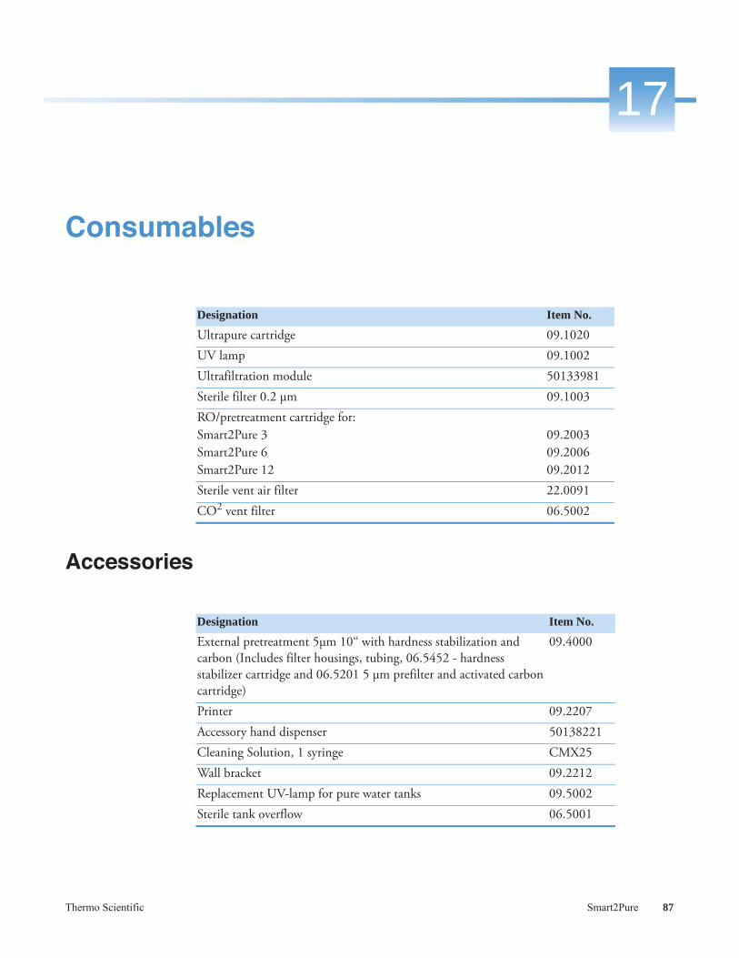
Thermo Scientific Smart2Pure 87
17
Consumables
Accessories
Designation Item No.
Ultrapure cartridge 09.1020UV lamp 09.1002Ultrafiltration module 50133981Sterile filter 0.2 μm 09.1003RO/pretreatment cartridge for:Smart2Pure 3Smart2Pure 6Smart2Pure 12
09.200309.200609.2012
Sterile vent air filter 22.0091CO2 vent filter 06.5002
Designation Item No.
External pretreatment 5μm 10“ with hardness stabilization and carbon (Includes filter housings, tubing, 06.5452 - hardness stabilizer cartridge and 06.5201 5 μm prefilter and activated carbon cartridge)
09.4000
Printer 09.2207Accessory hand dispenser 50138221Cleaning Solution, 1 syringe CMX25Wall bracket 09.2212Replacement UV-lamp for pure water tanks 09.5002Sterile tank overflow 06.5001

17 Consumables
88 Smart2Pure Thermo Scientific

Thermo Scientific Smart2Pure 89
18
Terminal assignment

18 Terminal assignment
90 Smart2Pure Thermo Scientific

Thermo Scientific Smart2Pure 91
19
Maintenance record
The following points must be observed in order to ensure the quality of the system.
1x / Weekly, enter measured values.
Customer address: Location:System type:Serial no.:Year made:
Date Ultrapure water resistance[M xcm]
Temperature
[°C]
Last change of RO/pretreatment cartridge
Last change of external pretreatment cartridge
Last change of UV lamp
Ultra pure water volume flow[l/h]
Last change of ultrapure cartridge
Last cleaning Last check of concentrate flow Signature

19 Maintenance record
92 Smart2Pure Thermo Scientific

Thermo Scientific Smart2Pure 93
20
Contact information Thermo Fisher Scientific
Contact address for service:Overview of Thermo Scientific international sales organizationPostal address in USA:Thermo Scientific275 Aiken RoadAsheville, NC 28804USAInquiries from USA/CanadaSales: +1 866 984 3766Service: +1 800 438 4851Enquiries from Latin AmericaSales: +1 866 984 3766Service: +1 866 984 3766Enquiries from Asia:ChinaSales: +86 10 8419 3588Service: toll-free 1-8008105118
Support Mobile 4006505118 or +86 10 8419 3588IndiaSales: +91 22 6716 2200Service: toll-free 1-800 22 8374 or +91 22 6716 2200JapanSales: +81 45 453 9220Service: +81 45 453 9224Inquiries from other countries Asia/ Australia/ New ZealandSales: +852 2885 4613Service: +65 6872 9720Inquiries from countries not listed here/ other EMEA countriesSales: +49 6184 90 6940 or +33 2 2803 2000Service: +49 6184 90 6940Enquiries from Europe:AustriaSales: +43 1 801 40 0Service : +43 1 801 40 0

20 Contact information Thermo Fisher Scientific
94 Smart2Pure Thermo Scientific
BelgiumSales: +32 53 73 4241Service: +32 53 73 4241Finland/Nordic/Baltic CountriesSales: +358 9 329 100Service: +358 9 329 100FranceSales: +33 2 2803 2180Service : +33 825 800 119GermanyPostal Address Germany:Thermo Electron LED GmbHRobert-Bosch-Straße 1D - 63505 LangenselboldPhone Sales: toll-free 0800 1 536 376
or +49 6184 90 6940Service: toll-free 0800 1 112110
or +49 6184 90 6940E-mail: [email protected]: +39 02 95059 341Service: +39 02 95059 250NetherlandsSales: +31 76 579 5555Service: +31 76 579 5639Russia/CISSales: +7 812 703 4215Service: +7 812 703 4215Spain / PortugalSales: +34 93 223 0918Service: +34 93 223 0918SwitzerlandSales: +41 44 454 1212Service: +41 44 454 1212UK/IrelandSales: +44 870 609 9203Service: +44 870 609 9203
© 2015 Thermo Fisher Scientific Inc. All rights reserved. All trademarks are the property of Thermo Fisher Scientific Inc. and its subsidiaries. Specifications, terms and pricing are subject to change. Not all products are available in all countries. Please consult your local sales representative for details.

Thermo Scientific Smart2Pure 95
I
AAccessibility to Smart2Pure systems and pure water tank 21Accessories 87Airborne sound emission 22Ambient conditions 22Attaching the wall holder for 30 or 60L pure water tank 36Attaching wall holder for 30L pure water tank 37Attaching wall holder for 60L pure water tank 40Autoclaving the sterile filter 76Available Smart2Pure 12 systems 13Available Smart2Pure 3/6 systems 12Available storage tanks for Smart2Pure 12 systems 13
CCommunication 61Complaints 2Connecting a external tank to the Smart2Pure 12
system 34Connections of the pure water tank Smart2Pure 12 30Connections of the Smart2Pure 12 system 28Connections of the Smart2Pure 3/6 system 26Consumables 87Contact information Thermo Fisher Scientific 93
DDimensions and weight 30L and 60L pure water tank
20Dimensions and weight of Smart2Pure12 19Dimensions and weight Smart2Pure 3/6 18Disinfection 6854 54
EElectrical connections 21Error message and acoustic error signal 61Examination on receipt 2Explanatory notes on the operating instructions ii
Extend of delivery 9Extend of Delivery Smart2Pure 12 11Extend of delivery Smart2Pure 3/6 10
FFeedwater requirements 17Flow chart 47
HHow the Smart2Pure system functions 49
IIllustration of drain 35Index 97Installation 25Intended Use 15Intended Use of the device 15
LLegal Information ii
MMaintenance 63Maintenance Intervals 64Maintenance record 91Materials of parts which contact water 21Menu 58Mono/dual measurement mode 58Mounting the power pack (voltage supply) 43
OOperating Elements 55
PPackaging for return shipment 2

Index: R
Permeate and concentrate performance for Smart2Pure 18
Preface iProduct water quality ASTM Type I (on dispensing
valve) 17Product water quality ASTM Type II (tank quality) 17Putting system into operation 52
RReplacement parts 81Replacement parts pure water tank for Smart2Pure 12
86Replacement parts Smart 2Pure 3/6 82Replacement parts Smart2Pure 12 84Replacing the pretreatment cartridge 66Replacing the sterile filter 76Replacing the ultrapure cartridge 65Replacing the UV lamp 74
SSafety Precautions 5Setting the limiting value for conductivity 59Setting the limiting value for temperature 60Standards and directives ivStart your Smart2Pure system into operation 31System control 57
TTechnical Specifications 17Terminal assignment 89The Installation area 23Transport and packaging 1Trouble shooting 79
UUnintended use 15UV-reactor assembly 73
VVenting the sterile filter 53
WWall mounting 42Warranty iiWaste disposal 77Water connections 20

Thermo Scientific Smart2Pure 97
I

Index:

Thermo Scientific Smart2Pure 99
I
Index

Index:
© 2016 Thermo Fisher Scientific Inc. All rights reserved. All trademarks are the property of Thermo Fisher Scientific Inc. and its subsidiaries. Specifications, terms and pricing are subject to change. Not all products are available in all countries. Please consult your local sales representative for details.
thermoscientific.co
Thermo Fisher Scientific
81 Wyman Street
Waltham, MA 02451
Thermo Fisher Scientific,
San Jose, CA USA is ISO Certified.