thermocode - odtech.co.uk new 2012/therm_5775/pdf/thermocode5775manual2004... · thermocode...
TRANSCRIPT

Thermocode 5775 Operator Instructions Issue 10, 22 January 1998
Page 1
THERMOCODE
OPERATOR INSTRUCTIONS PARTS LISTING
CIRCUIT DIAGRAMS INSTALLATION DETAILS
THERMOCODE 5775
Designed and manufactured by:
OPEN DATE EQUIPMENT LIMITED UNITS 8 & 9 PUMA TRADE PARK
145 MORDEN ROAD MITCHAM
SURREY CR4 4DG UNITED KINGDOM
Tel: 020 8655 4999
Fax: 020 8655 4990
Email: [email protected]
Web Site: www.opendate.co.uk

Thermocode 5775 Operator Instructions Issue 10, 22 January 1998
Page 2
Index Description Page No. Declaration of Conformity. 3 Safety Instructions. 4 Introduction. 5 System Overview. 5 Optional Extras. 5 Technical Information. 5 Installation Procedure 6 Thermocode Controlling Relays. 6 Plan View Power Supply Diagram 7 Print Signal Connections (24Volt Pulse) 8 Print Signal Connections (Voltage Free) 9 Standard Relay Configuration Chart 10 Low Foil Relay Configuration Chart 11 Sequence Relay Configuration Chart Thermocode Installed in a Standard Mounting Frame. 12 - 13 Hand Held Terminal layout and Specification 14 Thermal Ribbon Specification and Supplies 15 Printhead Warranty. 16 System Start Up. 17 Functions of Indicator LED’s. 18 Status Printout Details. 19 Ribbon Replacement, Repairing Ribbon Breaks. 20 Cassette Threading diagram. 21 Recommended Daily Maintenance. (Cassette Cleaning) 22 Recommended Daily Maintenance. (Printhead Cleaning) 23 Recommended Spares List. 24 Fault Finding. 25 - 26 Ribbon not Indexing Enough, Ribbon Indexing Excessive. 26 Ribbon Breaking or Perforated, Ribbon Tracking. 27 Print Quality problems 25
Thermocode Diagnostics Sheet 1 28 Thermocode Diagnostics Sheet 2 29
Airborne Noise Emissions. 30 Open Date Group companies Addresses 31 Agents Names & Addresses. 31

Thermocode 5775 Operator Instructions Issue 10, 22 January 1998
Page 3
EC DECLARATION OF CONFORMITY
We hereby declare that the following machinery complies with the essential health and safety requirements of the Machinery Directive 89/392/EEC, 91/368/EEC and 93/44/EEC enacted in the United Kingdom by the Supply of Machinery (Safety) Regulations 1992. Machine Description Thermal Transfer Printer Model Thermocode Type “S” Serial number ..................... Manufactured by Open Date Equipment Limited. Address Putney Bridge Road, London SW18 1TU, England. This machinery has been and manufactured in accordance with the following transposed harmonised European standards. EN292: parts 1 and 2, 1991. Safety of Machinery - Basic concepts, general principles of design. EN294: 1992. Safety of Machinery - Safety distances to prevent danger zones being reached by the upper limbs. EN60204: part 1, 1993. Safety of Machinery - Electrical equipment of machines - Specification for general requirements. EN50081: part 1, 1992. Electromagnetic compatibility - Generic emission standard. EN50082: part 2, 1992. Electromagnetic compatibility - Generic immunity standard. In addition, this machinery has been designed and manufactured in accordance with British Standard BS5304: 1988, Safety of Machinery. A technical construction file for this machinery is retained at the above address. Signed............................................ Date............................................ Name K.F. Wingfield. Position General Manager Being the responsible person appointed by Open Date Equipment Limited. This Declaration of Conformity complies with Regulation 22 of The Supply of Machinery (Safety) Regulations 1992.

Thermocode 5775 Operator Instructions Issue 10, 22 January 1998
Page 4
IMPORTANT SAFETY INSTRUCTIONS
1. Read these instructions carefully. Follow all warnings and instructions marked on the product. 2. Always disconnect the printhead and power supply from the mains electrical supply before
attempting to clean or service the product. 3. Never operate the printhead unless it is installed within the mounting frame supplied. When
installed correctly the gap between the printer and print base should not be greater than 2.5mm. 4. Do not use the product near water. Never spill liquid of any kind on to the product. 5. Do not place this product on an unstable stand, table or machine. It may fall causing serious damage to the product or injury to the operator. 6. Never insert objects of any kind into this product through any openings or gaps as they may touch
dangerous voltage points or short circuit parts that could result in fire or electric shock. 7. This product should only be operated from the type of electrical supply as indicated on the rear of the
printhead power supply unit. 8. Ensure that the printhead connection cable is fully secured to the printer and power supply with the
screws fitted within the “D” connector covers. Failure to do this will result in the machine not being properly earthed.
9. Use only the power cable supplied with the product. The cable supplied is three core, utilising one wire
as a grounding conductor. This must be connected to a suitable earthing point at the electrical supply. This is a safety feature. If any doubt arises in trying to connect the power cable, please contact the manufacturer or the agent who supplied the product.
10. Do not allow anything to rest on the power cable. Do not locate the product where persons will walk on
the cable. 11. If an extension cable is used with this product, make sure that the total ampere ratings of the
equipment plugged into the extension cable does not exceed the extension cable ampere rating. Also make sure that the total rating does not exceed the fuse rating.
12. Do not service this product yourself as opening or removing guards may expose you to dangerous
voltage points, major burns and other risks. Refer all servicing to qualified personnel. 13. Do not attempt to use to use this product in areas where explosive gases or substances are present. 14. Disconnect the product from the electrical and air supplies and refer servicing to qualified personnel
under the following conditions.
a. If the power cable is damaged or frayed. b. If the printer connection cables are damaged in any way. c. If liquid has been spilled into the product has been exposed to water.
d. If the product does not operate normally when the operating instructions are followed.
15. Adjust only those controls which are covered by these instructions. Improper adjustment may result in damage which will require qualified technicians to restore the product to normal operating conditions.

Thermocode 5775 Operator Instructions Issue 10, 22 January 1998
Page 5
INTRODUCTION This operator manual describes how to operate and maintain the Thermocode 5775 printer on a basic level. The mechanical adjustments that can be made to the printer are minimal. The only setting adjustment which has to be carried out is to level the printhead approximately in all directions, or to set the required clearance from the rubber print base within the frame. (See page 12 & 13) The printer has been designed to be controlled automatically by its own software or programmed by the operator using the hand held terminal or a computer.
SYSTEM OVERVIEW The following components are normally supplied for installation. (See page 12 & 13) A. Thermocode 5775 Printer - 200mm wide x 210mm high x 180mm deep. B. Power Supply Unit - 130mm wide x 110mm high x 280mm long.
(Complete with Power Cable attached, 110 Volt or 240 Volt Operation)
C. Two Power Supply Interconnection Leads - 1.5 metres long.
OPTIONAL EXTRAS D. Hand Held Terminal - 4 line x 16 character backlit display. (See page 14) E. PCMCIA Card, 512k capacity - storage of programs, fonts or formats. F. Standard or custom designed Mounting Frame. (See page 12) G. Windows based software design package - WYSIWIG. H. DOS based format writing package.
PRINTER TECHNICAL INFORMATION A. Maximum print area - 57mm x 75mm. (672 dots x 885 dots) B. Printhead resolution - 11.81 dots/mm or 300 dots per inch. C. Up to Ten fonts stored within the printer - Truetype or Bitmap. (228000 Kilobytes maximum Memory) D. Uni-directional or bi-directional printing. E. Print designs are stored along with Print Speed, Burn Value, Pressure, Peel height. F. Automatic updating of printer and terminal memory when editing formats. G. 110 or 220/240 volt operation, 50/60hz. H. Real Time/Date printing with specified offsets if required. J. Sequential Number and Barcode options - 16 different types. K. All text, graphics, lines and boxes can be printed in all four orientations. (0, 90, 180, 270 degrees)
PRINT BASE RUBBER SPECIFICATION Hardness:- 40 - 50 Shore Natural Rubber. Thickness:- 3.0mm Flatness:- Normally supplied with ground finish, -0.03mm to +0.03mm as heater specification.

Thermocode 5775 Operator Instructions Issue 10, 22 January 1998
Page 6
INSTALLATION PROCEDURES 1. Install the Thermocode printer in the Mounting Frame, ensuring that the orientation
for the application and clearance between the printer and print base rubber is correct. (See pages 12 & 13)
2. Connect the Printer and Power Supply using the interconnection leads. The leads are specifically keyed to prevent them from being fitted incorrectly, unless forced. Please ensure that the plugs and sockets match before tightening the screws. 3. Each installation must have an Automatic Print signal from the parent machine, this is normally a relay or 24 Volt pulsed output signal.
Please see the following pages:- Page 7 for Power Supply plan view (with top cover removed) Page 8 for Voltage Free Print signal connections. Page 9 for 24 Volt pulse Connection. Note!
The print signal can be delayed slightly if found necessary upon installation, see page 7 for adjusting the print signal delay time. (range 0 to 1 second)
The test button allows manual operation of a print cycle, this must be configured in relation to the print signal. Or for Product security reasons you may wish to disconnect this facility altogether.
Thermocode Controlling Relays Within the Thermocode Power supply are three relays, which can provide controlling signals to the parent machine. Each relay has two sets of contacts, Normally Open and Normally Closed, plus a Common for each. The relays have a maximum rating of 240 Volt, 7 amp. (See pages 10 & 11 for connection details) Fault Relay (Relay 3)The Fault relay operates when the Thermocodes internal sensors detect a fault or error condition. Typical examples of this are when the Cassette is removed or if the Thermal Ribbon is broken. The relay should be connected to inhibit the parent machine should a printer fault occur.
Start/Low Foil Relay (Relay 2) This relay can be used for one of two functions, which are determined by how the Printer was programmed upon installation. Function 1, Normally used for controlled synchronization applications only. The printer can be programmed so that the relay gives a trigger or signal to the parent machine. Function 2, Used as a low ribbon warning. The printer can be programmed to operate this relay when the amount of Thermal Ribbon left in metres reaches the pre-programmed amount. The relay can be used to stop the parent machine and printer or just the printer.
Stop Relay/Sequence (Relay 1) The Stop relay should be used to prevent the parent machine from beginning it’s cycle until the Thermocode has finished printing. The relay will change over when the printer receives a start or trigger signal and will stay activated until the print cycle is complete. Function 1, Normally used for controlled synchronisation applications only. The printer can be programmed so that the relay gives a trigger or signal to the parent machine. Function 2, Used as a SEQUENCE Relay, The printer can be programmed to operate this relay to inhibit a parent machine, from indexing the substrate whilst the Printer is printing. The difference between this function and the normal STOP RELAY, is that if you remove the cassette or cause any other Printer malfunction it does not allow this relay to operate.

Thermocode 5775 Operator Instructions Issue 10, 22 January 1998
Page 7
POWER SUPPLY DETAILS
TOP COVER REMOVED

Thermocode 5775 Operator Instructions Issue 10, 22 January 1998
Page 8
SIGNAL WIRES
CONNECT TEST BUTTON TO “B”
POSITION LINKS AS SHOWN,LINK PINS NEXT TO 1 & 3.
25 Turn Potentiometer,Turn clockwise to increase delay. 0 - 1 second range.
24 VOLT PULSE PRINT SIGNAL CONFIGURATION
PLAN VIEW OF I/O BOARD, See Page 7 for Location of Board
- +

Thermocode 5775 Operator Instructions Issue 10, 22 January 1998
Page 9
SIGNAL WIRES
CONNECT TEST BUTTON TO “A”
POSITION LINKS AS SHOWN,LINK PINS NEXT TO 2 & 4.
25 Turn Potentiometer,Turn clockwise to increase delay. 0 - 1 second range.
VOLTAGE FREE PRINT SIGNAL CONFIGURATION
PLAN VIEW OF I/O BOARD, See Page 7 for Location of Board

Thermocode 5775 Operator Instructions Issue 10, 22 January 1998
Page 10
THERMOCODE 5775 STANDARD RELAY CONFIGURATION
SOFTWARE
VERSION TPHC4_02.A21
FAULT RELAY
(Relay 3) NO / NC
START RELAY
(Relay 2) NO / NC
STOP RELAY
(Relay 1) NO / NC
NO POWER
NO / NC
NO / NC
NO / NC
POWER
READY TO PRINT
NC / NO
NC / NO
NO / NC
WHILST
PRINTING
NC / NO
NO / NC
NC / NO
AFTER
PRINTING
NC / NO
NC / NO
NO / NC
CASSETTE REMOVED
NO / NC
NO / NC
NC / NO
RIBBON
BROKEN OR OUT
NO / NC
NO / NC
NC / NO
PRINTER ERROR
NO / NC
NO / NC
NC / NO
RIBBON
LOW
NC / NO
NC / NO
NO / NC
NC = NORMALLY CLOSED
NO = NORMALLY OPEN

Thermocode 5775 Operator Instructions Issue 10, 22 January 1998
Page 11
THERMOCODE 5775 LOW FOIL RELAY CONFIGURATION
SOFTWARE
VERSION TPHC4_02.A21
FAULT RELAY
(Relay 3) NO / NC
LOW FOIL RELAY
(Relay 2) NO / NC
STOP RELAY
(Relay 1) NO / NC
NO POWER
NO / NC
NO / NC
NO / NC
POWER
READY TO PRINT
NC / NO
NC / NO
NO / NC
WHILST
PRINTING
NC / NO
NC / NO
NC / NO
AFTER
PRINTING
NC / NO
NC / NO
NO / NC
CASSETTE REMOVED
NO / NC
NC / NO
NC / NO
RIBBON
BROKEN OR OUT
NO / NC
NC / NO
NC / NO
PRINTER ERROR
NO / NC
NC / NO
NC / NO
RIBBON
LOW
NO / NC
NO / NC
NC / NO
NC = NORMALLY CLOSED
NO = NORMALLY OPEN

Thermocode 5775 Operator Instructions Issue 10, 22 January 1998
Page 12
THERMOCODE 5775 SEQUENCE RELAY CONFIGURATION
SOFTWARE
VERSION TPHC4_02.A21
FAULT RELAY
(Relay 3) NO / NC
LOW FOIL RELAY
(Relay 2) NO / NC
SEQUENCE
(Relay 1) NO / NC
NO POWER
NO / NC
NO / NC
NO / NC
POWER
READY TO PRINT
NC / NO
NC / NO
NO / NC
WHILST
PRINTING
NC / NO
NC / NO
NC / NO
AFTER
PRINTING
NC / NO
NC / NO
NO / NC
CASSETTE REMOVED
NO / NC
NC / NO
NO / NC
RIBBON
BROKEN OR OUT
NO / NC
NC / NO
NO / NC
PRINTER ERROR
NO / NC
NC / NO
NO / NC
RIBBON
LOW
NO / NC
NO / NC
NO / NC
NC = NORMALLY CLOSED
NO = NORMALLY OPEN
Thermocode 5775 Operator Instructions Issue 10, 22 January 1998
Page 13
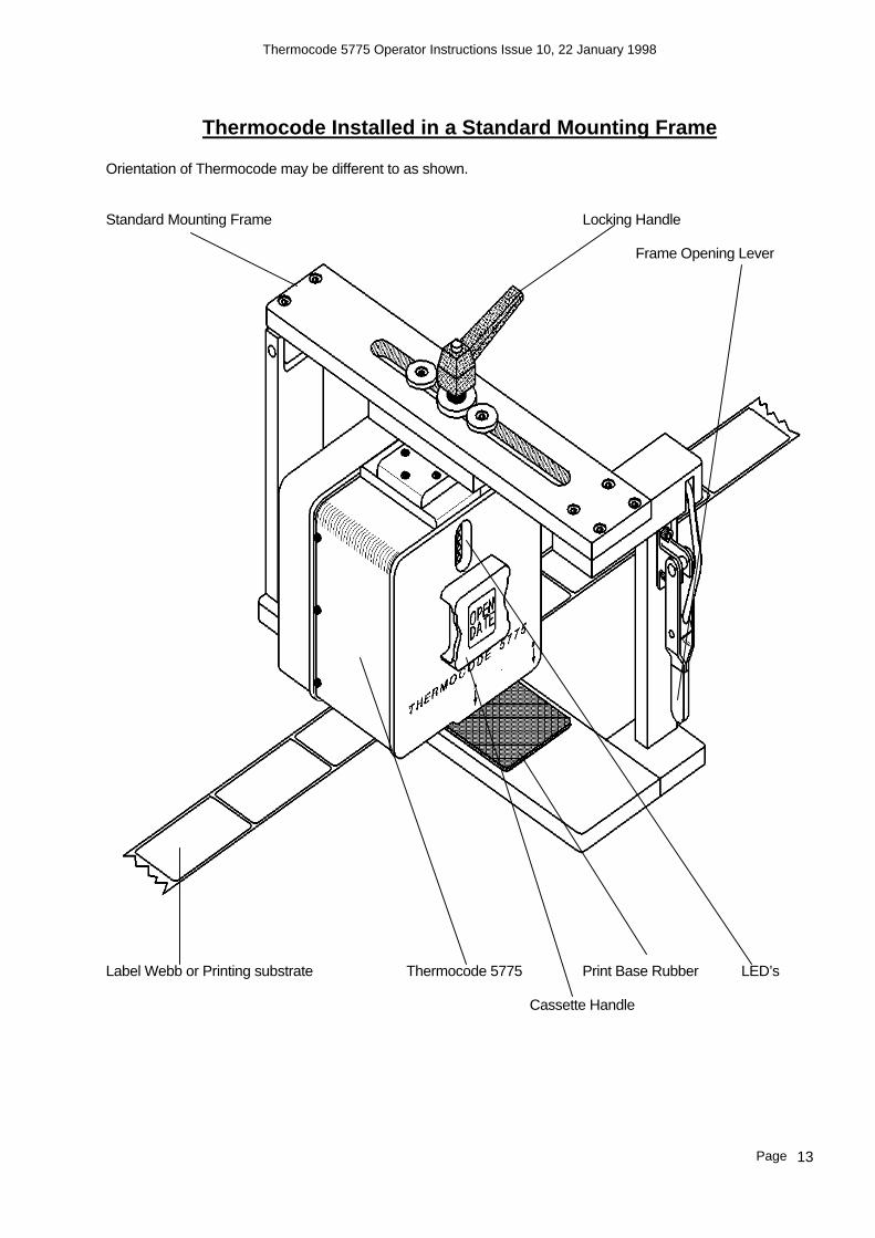
Thermocode Installed in a Standard Mounting Frame
Orientation of Thermocode may be different to as shown. Standard Mounting Frame Locking Handle Frame Opening Lever
Label Webb or Printing substrate Thermocode 5775 Print Base Rubber LED’s Cassette Handle

Thermocode 5775 Operator Instructions Issue 10, 22 January 1998
Page 14
2.5mm Clearance Dimension

Thermocode 5775 Operator Instructions Issue 10, 22 January 1998
Page 15
“Shift” Key used to selectbetween Upper or Lower case Alphabetical Characters
“Escape” Key, also used to delete characters when editing Parameter or Text fields.
26 Alphanumeric Keys, using the Downshift Key selects numbers or punctuation.
Right Sideways Arrow Key, used to move cursor under character to change or delete.
Left Sideways Arrow Key, used to move cursor under character to change or delete.
Up and Down Arrow Keys, used to select an item from the menu’s or scroll through spe-cial text when editing.
“ENTER” key, used to select a Menu function that you have highlighted with the cursor symbol, or to accept Text that has been changed.
CURSOR SYMBOL MAIN MENU
INDICATOR LED’S
DOWNSHIFT KEY
ALPHANUMERIC KEYPAD
TECHNICAL SPECIFICATION
Maximum Current 280 milliamps with Backlight Height 210 millimetres Width 100 millimetres Depth 30 millimetres
PCMCIA Card Type “S” RAM (512 Kilobytes) Connector Details 9 Way “D” Connector, Cable attached
PIN No. 1 Not used PIN No. 2 RXD PIN No. 3 TXD PIN No. 4 Not used PIN No. 5 GROUND PIN No. 6 Not used PIN No. 7 RTS PIN No. 8 CTS PIN No. 9 + 5 VOLT

Thermocode 5775 Operator Instructions Issue 10, 22 January 1998
Page 16
SILICONE COATING OUTSIDE CARDBOARD CORE
WAX/RESIN PIGMENT INSIDE WOUND
NO LEADERS OR TRAILERS REQUIRED ON FOIL
Open Date Ribbon Supplies Open Date Equipment Ltd, stocks 4 General purpose types of Thermal ribbon, these are available on a next day delivery if you require. Part Number Type Grade Quantity Substrate type TTR603901 Wax/Resin 503 Black 10 rolls Packaging films, Polyethylene etc
Low temperature release TTR603902 Wax/Resin APR4 White 10 rolls Packaging films, Polyethylene etc
TTR603903 Wax/Resin APR4 Black 10 rolls Labels and Packaging films
TTR603907 Resin AXR7+ 10 rolls Labels and Packaging films
difficult surfaces High Temperature release

Thermocode 5775 Operator Instructions Issue 10, 22 January 1998
Page 17
Standard Warranty Terms and Conditions – Thermal Printers.
Open Date Thermal Printers carry a twelve (12) month return to base (at our discretion) warranty, with the exception of the following parts;- 1. Thermal Printhead. 2. Print Base Rubber. The Printhead carries a fifty (50) kilometre / six (6) month (whichever is the sooner) warranty providing that full width (60mm) thermal transfer ribbon supplied by Open Date is used. Should the printhead fail during this period, the replacement head will carry the balance of the existing warranty. If the machine is running on ribbon not of Open Date supply, the warranty is reduced to three (3) months or twenty five (25) kilometres (whichever is the sooner) unless otherwise agreed. The printhead warranty will not be valid if;- 1. Mechanical damage is apparent from abuse. 2. Excessive wear on edges of printhead from using narrow ribbon. 3. No status printout is supplied. 4. Printhead resistance is not set correctly. 5. The date is not correct. 6. The metre counter has been reset. 7. Cleaning procedures have not been followed. 8. Installation and maintenance procedures are not correct. 9. If the machine is running on Thermal Print Base not of Open Date supply. The Print Base carries no warranty as it is considered to be a consumable item. We reserve the right to charge for components replaced during the warranty period which subsequently are found to be damaged due to any of the above conditions not being followed.

Thermocode 5775 Operator Instructions Issue 10, 22 January 1998
Page 18
System Start-up Sequence. When the printer is first switched on the red and green LED’s are illuminated for approximately 10 seconds. During this period you can if required, download a complete new operating system to the printer. Once this period is over the red LED will go out until the printer has generated the image that is currently stored in its memory. At this point the yellow LED will come on and the printhead will lower itself to the pre-print position, ready to start operation.
Functions of indicator LED’s. The LED’s are a method indicating the status of the printer to the operator. Please see the Fault finding chart And diagnostic sheets at the back of this manual. When using the Chart’s, please refer to the Thermocode 5775 Front View Diagram.

Thermocode 5775 Operator Instructions Issue 10, 22 January 1998
Page 19
STATUS PRINTOUT DETAILS Shown below is a typical Status Printout:-
Open Date Equipment Version 4.02 Built Dec 22 1997 20/10/98 12:31 Rib len=390 thk=11.5 W len=10 C diam=33.5 P dist=0 Prep=9.8 Head R=1984 Fnt:Swiss ARIALBD Fnt:OCRB Univers6 Fnt:Univers8 Internfont Fmt:TEST
The above text has vertical and horizontal lines around the text, allowing checking of any missing pixels or printhead damage. The width of the horizontal lines are the maximum pixels that can be printed (672), any gapswould indicate Printhead or Print base damage.
Status Details Line 1 = Company name of Software owners. Line 2 = Software Version Number. Line 3 = Date Software compiled. Line 4 = Date and time in Memory of printer. (date format could be either DD/MM/YY or MM/DD/YY or YY/MM/DD dependant on factory settings). Line 5 = Ribbon length in metres and thickness in microns. Line 6 = Ribbon Warning length in metres and Cassette cardboard core outside diameter in millimetres. Line 7 = Print Distance of Printhead in Metres and Preprint height of printhead. Line 8 = Printhead Resistance in ohms. Line 9 = Lists font names loaded to printer. Line 10 = Lists font names loaded to printer. Line 11 = Lists font names loaded to printer. Line 12 = Name of Format Loaded to Printer.
Note! The amount of font names and lines listed will vary with each machine.
Printing the Status Printout Remove Cassette, place a piece of Thermal paper (Fax type paper) under printhead and hold inposition. Press in the Cassette plunger and then the Ribbon reset button, then release both. In about 10 seconds the printer will perform the status printout for your information of
the printer settings and configuration. 4. Replace Cassette, you may have to wait a few seconds before the printer is ready to carry on with production as it has to re-generate the image it was printing before.

Thermocode 5775 Operator Instructions Issue 10, 22 January 1998
Page 20
Ribbon Replacement. 1. When using these instructions refer to the Cassette Threading Diagram. (Page 20) 2. Remove the cassette from the printer by pressing the latch in towards the handle and withdrawing the
cassette away from the body. 3. Remove and discard the used ribbon from the Rewind Spool. 4. Remove and discard the empty cardboard core from the Take-off Spool. 5. If necessary, clean all rollers and ribbon guides with the recommended cleaning solution. 6. Fit the new roll of ribbon on to the Take-Off Spool making sure that the direction of unwind is correct. 7. Fit the new cardboard core to the Rewind Spool. 8. Thread the ribbon as per the threading diagram and firmly attach the end to the cardboard core on the
Rewind Spool. 9. Wind on the Rewind Spool by approximately two turns, ensuring that the ribbon tracking is correct and that
there are no creases or overlaps that could affect the printing. 10. PRESS THE RIBBON RESET BUTTON. This resets the ribbon counter telling the printer that a new roll has
been loaded. 11. Refit the cassette by sliding it onto the body by and pushing it firmly so that it latches on. Note.If you fail to press the Ribbon Reset Button after you have replenished the ribbon, there is a danger of the printer not indexing the correct amount or it breaking. 1. When using these instructions please refer to the Cassette Threading Diagram. (Page 20) 2. Remove the Cassette from the printer by pressing the latch in towards the handle and withdrawing the
Cassette away from the body. 3. Carefully and neatly wind any loose ribbon on to the Rewind Spool. 4. Re-thread the existing roll of ribbon from the Take-Off Spool as per the threading diagram and firmly
attach the end to the roll of ribbon on the Rewind Spool. 5. Wind on the Rewind Spool by approximately two turns, ensuring that the ribbon tracking is correct and
that there are no creases or overlaps that could affect the printing. DO NOT PRESS THE RIBBON RESET BUTTON.
6. Refit the cassette by sliding it onto the body by and pushing it firmly so that it latches on. Note. If you press the Ribbon Reset Button after you have repaired the ribbon, there is a danger of the
printer not indexing the correct amount or it breaking. When using these instructions please refer to the Cassette Threading Diagram. (Page 20) 1. Remove the Cassette from the printer by pressing the latch in towards the handle and withdrawing
the cassette away from the body. 2. Carefully and neatly wind any loose ribbon on to the Rewind Spool. 3. Re-thread the existing roll of ribbon from the Take-off Spool as per the Threading Diagram and firmly
attach the end to the roll of ribbon on the Rewind Spool. 4. Wind on the Rewind Spool by approximately two turns, ensuring that the ribbon tracking is correct
and that there are no creases or overlaps that could affect the printing. DO NOT PRESS THE RIBBON RESET BUTTON.
5. Refit the cassette by sliding it onto the body by and pushing it firmly so that it latches on. Note. If you press the Ribbon Reset Button after you have repaired the ribbon, there is a danger of the printer not indexing the correct amount or it breaking.

Thermocode 5775 Operator Instructions Issue 10, 22 January 1998
Page 21
Cassette Threading Diagram Take off Spool Rewind Spool
Cardboard Core
Pigment Inside Wound
See Page 15 for Ribbon Specifications.
Thermocode 5775 Operator Instructions Issue 10, 22 January 1998
Page 22
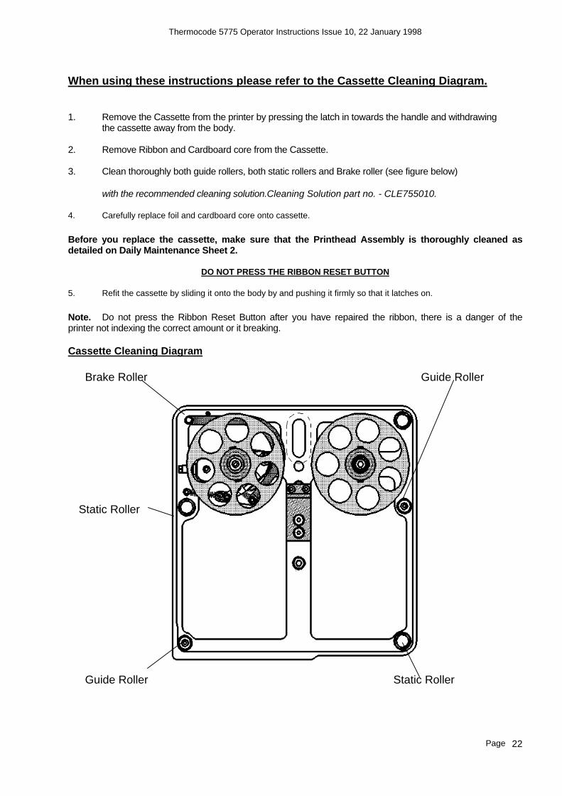
When using these instructions please refer to the Cassette Cleaning Diagram. 1. Remove the Cassette from the printer by pressing the latch in towards the handle and withdrawing the cassette away from the body. 2. Remove Ribbon and Cardboard core from the Cassette. 3. Clean thoroughly both guide rollers, both static rollers and Brake roller (see figure below)
with the recommended cleaning solution.Cleaning Solution part no. - CLE755010.
4. Carefully replace foil and cardboard core onto cassette. Before you replace the cassette, make sure that the Printhead Assembly is thoroughly cleaned as detailed on Daily Maintenance Sheet 2.
DO NOT PRESS THE RIBBON RESET BUTTON
5. Refit the cassette by sliding it onto the body by and pushing it firmly so that it latches on. Note. Do not press the Ribbon Reset Button after you have repaired the ribbon, there is a danger of the printer not indexing the correct amount or it breaking.
Cassette Cleaning Diagram
Brake Roller Guide Roller
Guide Roller Static Roller
Static Roller

Thermocode 5775 Operator Instructions Issue 10, 22 January 1998
Page 23
Recomended Daily Maintenance (Printhead Cleaning) see diagram below 1. Remove the Cassette from the printer by pressing the latch in towards the handle and withdrawing the cassette away from the body. 2. Access the Printhead Assembly by either raising the printer mounting frame or moving the print
base.Not all installations are identical so it is impossible to give full instructions to gain access for cleaning.
3. Pressing in the Cassette plunger, will lower the Printhead assembly to the programmed pre-print
position allowing easier access for cleaning. 4. Connect yourself to ground using a suitable earth strap.
DO NOT TOUCH THE PRINTHEAD WITH YOUR HANDS, STATIC ELECTRICITY CAN DAMAGE IT. 5. Using the correct cleaning solution on either a Safewipe cloth or Safebud, the Printhead, guide bars and
rollers should be thoroughly cleaned, ensure that all foreign matter is removed.
Printhead cleaning solution, part no. CLE755010 Safewipes (pack of 100) part no. WIP755011 Safebuds (pack of 25) part no. BUD755013
6. Before re-assembling the machine and for optimum printing conditions, make sure that you thoroughly
clean the print base. Ribbon Reset button Cassette Plunger
Printhead Roller Printhead Roller Guide Bar Guide Bar
Ceramic Printhead

Thermocode 5775 Operator Instructions Issue 10, 22 January 1998
Page 24
RECOMMENDED SPARES LIST
Covering:THERMOCODE 5775.
ELECTRONIC STOCK REF
1. Printhead Assembly. PRI755000 2. Ribbon Cable - Printhead power. CAB755002 3. Ribbon Cable - Printhead signal. CAB755003 4. Ribbon Cable - Vertical motor. CAB755004 5. Cable - Hand Held Terminal. LEA755022 6. Microswitch - Pressure. MIC755005 7. Microswitch - Vertical. MIC755006 8. Microswitch Screws (4 required). KIT755016 9. Fuse Set - Power Supply. FUS755007
MECHANICAL STOCK REF 10. Timing Belt. BEL755001 11. Brake Pads (pack of 5). BRA755009 12. Spring Set - Magazine. SPR755008 13. Spring Clips - Magazine - (pack of 8). SPR755015 14a. Print Base Rubber Sheet (300 x 300mm). PRI755012 14b Print Base Rubber Pad (245 x 85mm). PAD754010 14c Print Base Rubber Pad (85 x 85) PAD754030
CLEANING MATERIALS STOCK REF 15. Head Cleaning Fluid. CLE755010 16. Safewipes (pack of 100). WIP755011 17. Cleaning Buds (pack of 25). BUD755013

Thermocode 5775 Operator Instructions Issue 10, 22 January 1998
Page 25
FAULT FINDING Ribbon Indexing not Enough (Prints Overlapping) Q. Black RIBBON RESET button not pressed when a new reel of foil was fitted. A. Strip off all waste foil from rewind spool, re-thread cassette, press RIBBON RESET button and
replace Cassette. Q. Settings in the Factory parameters do not match the foil being used. A. Check the Factory parameters and re-program Printer and Terminal, Service Engineer may be
required. Rewind Cardboard core must be measured and input to Factory file.
Total Foil thickness in microns must be known and input in the Factory file.
Outside Diameter of Foil reel must be known and input in the Factory file.
Foil capacity, length in metres must be known and input in the Factory file. Q. Cardboard Core does not fit the Rewind spool Correctly, or is missing. A. Fit correct cardboard core, ensure it is located on the spring clips correctly. Q. Foil not attached to Cardboard core correctly. A. Use selotape to attach Foil to cardboard core, and wind on a few turns. Q. Cassette rollers, Printhead rollers or Printhead Assembly are dirty, through build up of
wax/resin residue. A. Clean cassette and Printhead as described in maintenance section. Q. Tension arm BRAKE PAD worn or dirty A. Renew BRAKE PAD. Q. Tension arm spring tension on BAND BRAKE not set correctly. A. Adjust BAND BRAKE as per drawing. (REF 757006) Ribbon Indexing Excessive Q. Settings in the Factory parameters do not match the foil being used. A. Check the Factory parameters and re-program Printer and Terminal, Service Engineer may be
required. Rewind Cardboard core must be measured and input to Factory file.
Total Foil thickness in microns must be known and input in the Factory file.
Outside Diameter of Foil reel must be known and input in the Factory file. Foil capacity, length in metres must be known and input in the Factory file.

Thermocode 5775 Operator Instructions Issue 10, 22 January 1998
Page 26
Q. The Format design has a space before printing any Characters.Foil may be sticking to Substrate being printed, and being pulled along. A. Adjust the PRE-PRINT position, or add a PEEL HEIGHT value to the format. This will stop the foil from sticking, different substrates will need different values. Service Engineer may be required.
Ribbon Breaking or Perforated Q. Cassette rollers, Printhead rollers or Printhead Assembly are dirty, through build up of
wax/resin residue. A. Clean cassette and Printhead as described in maintenance section. Q. Foil may be sticking to Substrate being printed, and being pulled along. A. Adjust the PRE-PRINT position, or add a PEEL HEIGHT value to the format. This will stop the foil
from sticking, different substrates will need different values. Service Engineer may be required. Q. Temperature “BURN” values may be set to high for the substrate being printed. A. Reduce “BURN” values of format to achieve acceptable print quality, if you are bi-directional printing remember to adjust both values for “A” to “B” and “B” to “A” directions. Q. Foil indexing overlapping for each print. A. See page 24 (Foil indexing not enough)section 6.00 to overcome overlapping problems.
Ribbon Tracking on Cassette Q. Cassette rollers, Printhead rollers or Printhead Assembly are dirty, through build up of
wax/resin residue. A. Clean cassette and Printhead as described in maintenance section ???? Q. Foil may be sticking to Substrate being printed, and being pulled to one side. A. Adjust the PRE-PRINT position, or add a PEEL HEIGHT value to the format. This will stop the foil
from sticking, different substrates will need different values. Service Engineer may be required. Q. Cassette may have been dropped, damaging tracking rollers or Tension arm. A. Call for Service Engineer or send back to manufacturer for checking.

Thermocode 5775 Operator Instructions Issue 10, 22 January 1998
Page 27
Print Quality Problems Q. Print not consistent over printed area. A. Ribbon not compatible with substrate.
Temperature setting not high enough. Low printing temperatures can give the effect of the edges of characters appearing feint or ragged.
Damaged or dirty print base, clean and check for any imperfections. Normal Thermocode print bases are 45-50 shore hardness rubber which is bonded to the aluminium backing sheet and then ground. Flatness of this pad is very important, on some labelling machines if the backing webb is not aligned correctly it will cut into the print base or actually mis-shape it due to the tension of the backing webb.
Printer not correctly mounted in Frame.
Printer frame not manufactured to correct dimensions, clearance under printer excessive. See page ?? for Standard Frame measurements.
Printhead Dirty or Pixels burnt out. Clean Printhead and create status print on plain fax paper to confirm Printhead condition. See section ????.
Ribbon Indexing not enough. See section 6.0 Ribbon tracking on magazine, causing creasing. See section 6.2 Ribbon perforated, see section 6.30 Ribbon foil INK Coating inconsistent.

Thermocode 5775 Operator Instructions Issue 10, 22 January 1998
Page 28
THERMOCODE DIAGNOSTICS SHEET1
FAULT DESCRIPTION REMEDY / ACTION
1
No Power to Printer / No Voltage to Power supply
1. Check Mains fuses in Plug and Power Supply. 2. Check Voltage is at Source. 3. Check the 24Volt + 5Volt fuses in Power Supply. 4. Check All Electrical connections are correct.
2
Cassette Removed / Ribbon Broken or Loose 1. Replace Cassette. 2. Check Cassette Band Brake Tension. 3. Replace or Repair Thermal ribbon
3
Low Foil Warning 1. Replace Thermal Ribbon on Cassette and press reset Black Button below LED’s.
4
Print Quantity Reached / No format Loaded after Programming the machine.
1. Load a New Format. 2. Send a new Quantity Amount.
5
Format Loading / No Format Loaded. 1. Wait for a few minutes to see if a format is loading. 2. Load a new Format.
6
No font Loaded to Printer for Format requirement.
1. Load the correct Font to printer and load Format again. 2. Load a different format that has printer Fonts. 3. Check which Fonts have been loaded to printer, by making a Status printout.
7
Format Co-ordinates not correct for Print Area 1. Check each Format field line for errors. 2. Re-load format to correct error.
8
Format Loaded, awaiting Print Signal. 1. Normal Condition
9
Linear Home sensor “A” not registering or Faulty. 1. Check Belt is not broken and tensioned correctly. 2. Check Linear Motor has power applied. 3. Check debris is not stopping full movement linearly. 4. Check Wire crimps and connections. 5. Check indication on LED bar. 6. Replace Sensor assembly.
10
Linear Home sensor “B” not registering or Faulty. 1. Check Belt is not broken and tensioned correctly. 2. Check Linear Motor has power applied. 3. Check debris is not stopping full movement linearly. 4. Check Wire crimps and connections. 5. Check indication on LED bar. 6. Replace Sensor assembly.
11
Pressure Switch Faulty, whilst trying to Print. 1. Check the Mounting Frame is not Open. 2. Check the 2.5mm gap between Printer and Print Base. 3. Check Adjustment of Pressure sensor Screw. 4. Check Sensor Assembly has not come loose. 5. Check Wire crimps and connections. 6. Check Blue Ribbon cable is connected properly. 7. Check LED on sensor activates correctly. 8. Check Print Base Rubber is not damaged or missing. 9. Check Pressure setting within Format Parameters.
12
Vertical Home Sensor Faulty. 1. Check Adjustment of Vertical sensor Screw. 2. Check Sensor Assembly has not come loose. 3. Check Wire crimps and connections. 4. Check Blue Ribbon cable is connected properly. 5. Check LED on sensor activates correctly.
13
Pressure Switch Activated out of sequence. 1. Excessive Tension of Ribbon on cassette. 2. Faulty Switch, replace.
14
Vertical Home Switch Activated out of Sequence. 1. Vertical Motor Disconnected, faulty. 2. Faulty Switch, replace.
15
Printhead Temperature to High. 1. Excessive heat generated by Vertical Motor, due to wrong current settings in Power supply

Thermocode 5775 Operator Instructions Issue 10, 22 January 1998
Page 29
THERMOCODE DIAGNOSTICS SHEET 2
FAULT DESCRIPTION REMEDY / ACTION
16 Printhead Thermistor Fault / Disconnected 1. Check Blue Ribbon Cable is fitted correctly to Printhead and interconnect PCB. 2. Faulty Printhead, replace.
17 Processor Fault / Watchdog Failed. 1. Check 5 Volt within the Printer and Power Supply is not low or irregular. 2. Re-program complete system. 3. Replace and re-program Processor and Control circuit Boards.
18 Character Generator Failed. 1. The Font loaded to printer is corrupted. 2. Characters being generated are too large for Memory. 3. Init and re-load fonts in Printer.
19 Font size wrong / incorrect 1. Alter Font sizes in Text fields, to correct. 2. Load correct specified Bit Map font for Format.
20 Barcode Failed, characters or code unrecognised.
1. Wrong characters in Barcode string. 2. To many characters in Barcode string. 3. Barcode type not recognised.
21 Allocated Memory Fail 1. Init Printer and re-load Software. 2. Replace Processor and Control Circuit Boards.
22 Printhead Linear Position incorrect 1. Check Belt is not broken and tensioned correctly. 2. Check Linear Motor has power applied. 3. Check debris is not stopping full movement linearly. 4. Check the Home position has been programmed correctly. 5. Check Both home sensors are functioning correctly.
WARNING If any of the faults occurr, you should correct the error condition before continuing with production. YELLOW LED FAULTS:- Are generally programming errors, and must be corrected before allowing the Printer to continue Production operations. Ideally you will correct the programming errors and then re-load the Format to the Printer. RED LED FAULTS:- Are generally Mechanical or Electrical faults, these may be resolved by simply removing and then replacing the cassette. Ideally the fault will be rectified correctly before trying to continue Production.

Thermocode 5775 Operator Instructions Issue 10, 22 January 1998
Page 30
AIRBORNE NOISE EMISSIONS. Comprehensive tests have been carried out with the Thermocode fitted in a standard printer frame and mounted onto a typical label applicator. Measurements were taken at 1.6 metres above floor level and approximately 1 metre away from the printer in all directions. The measuring equipment used for conducting the tests was a Digital Sound Level Meter, type d-1405E supplied by Lucas CEL. Before the tests were carried out the instrument was calibrated and fitted with a foam windsheild. The noise levels shown below are the equivalent continuous “A-weighted” sound pressure levels in decibels “dB(A)”.
PRINTER STATUS
NOISE LEVEL - DECIBELS (dB)
Awaiting Print signal 0 Continuously printing 66

Thermocode 5775 Operator Instructions Issue 10, 22 January 1998
Page 31
OPEN DATE GROUP COMPANIES
FRANCE
OPEN DATE FRANCE Z.I. D’Attichy, 60350 Attichy,
France. Local Tel:- 03 44 42 94 43 Local Fax:- 03 44 42 17 17 International Tel:- (0033) 3 44.42.94.43 International Fax:- (0033) 3 44.42.17.17
GERMANY
OPEN DATE GmbH PO Box 27 Schraggasse 14
97264 Helmstadt Local Tel:- 09369 9824 0 Local Fax:- 09369 9824 24 International Tel:- +49 9369 9824 0 International Fax:- +49 9369 9824 24
USA
OPEN DATE SYSTEMS INC. Springfield Road
PO BOX 583 Georges Mills
NH 03751-0538 Local Tel:- 603 763 3444 Local Fax:- 603 763 4222 International Tel:- +1 603 763 3444 International Fax:- +1 603 763 4222
INTERNATIONAL AGENTS & DISTRIBUTORS
Please visit www.opendate.co.uk for a list of international agents & distributors