thermodynamics review
DESCRIPTION
Thermodynamics Review. Craig Bradshaw, Lambert Fellow and PhD Candidate Slides provided by Prof. S. F. Son, and M. Mathison Adapted from Prof. G. A. Risha and other sources such as Kaplan AEC Education. THE FIRST LAW OF THERMODYNAMICS - PowerPoint PPT PresentationTRANSCRIPT

Thermodynamics Review
THE FIRST LAW OF THERMODYNAMICS• Energy cannot be created or destroyed,
but transformed into different forms• Applies to systems classified as either
closed or open
THE FIRST LAW OF THERMODYNAMICS• Energy cannot be created or destroyed,
but transformed into different forms• Applies to systems classified as either
closed or open
Thermodynamics is the transformation of energy
Craig Bradshaw, Lambert Fellow and PhD Candidate
Slides provided by Prof. S. F. Son, and M. Mathison
Adapted from Prof. G. A. Risha and other sources such as Kaplan AEC Education

Thermodynamic Systems
E stored E in E out E gen
genoutinstored EEEE
Energy Balance: Finite Time
Energy Balance: Rate
Win < 0
Wout > 0Qin > 0
Qout< 0
What is your system?Closed (fixed mass) or open (fixed volume)
Energy Transfer by Work and Heat:
Engines burn fuel to put heat into the system and produce
work (out of the system)
Engines burn fuel to put heat into the system and produce
work (out of the system)

Fixed Mass: Closed System
WQΔPEΔKEΔU
WQΔE
WQdt
dE
stored
cv
Note: Closed systems are a subset of open systems

Systems and Sign Convention
Consider a system that contains a lightbulb powered by electricity. Which of the following is true?
a) Positive work, positive heat transfer
b) Positive work, negative heat transfer
c) Negative work, positive heat transfer
d) Negative work, negative heat transfer
Which of the following would be considered a closed system?
a) A pump
b) A tire
c) A turbine
d) A jet nozzle
++ --0 WQdt
dEcv WQ
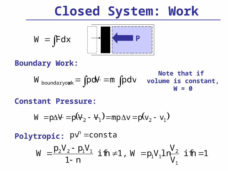
Closed System: Work
pdvmVpdW orkboundary w
Boundary Work:
Constant Pressure:
1212 vvpvmpVVpVpW
Note that if volume is constant,
W = 0
P FdxW
Polytropic: constant pvn
1nifV
VlnVpW1,nif
n1
VpVpW
1
211
1122

Work: Special Cases (Ideal Gas)
2
1
1
2
p
pmRTln
v
vmRTlnW
Constant Temperature:
Isentropic: s2 = s1
k
1k
1
211122
p
p1
1k
mRT
k1
VpVpW
constant pv
constant pvk
specific heat ratio,
RT pv Ideal Gas Law: mRT pV
v
p
c
ck

Closed System Work
When using the previous equations for boundary work, it must be assumed that a quasi-equilibrium process exists. If a quasi-equilibruim process exists, we have assumed
a) The pressure at any instant to be everywhere constant.
b) An isothermal process.
c) The heat transfer to be small.
d) The boundary motion to be infinitesimally small.
e) That no friction exists.
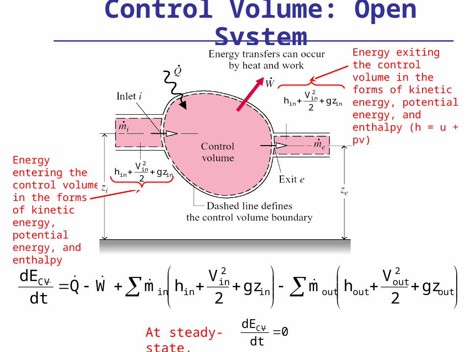
Control Volume: Open System
Energy entering the control volume in the forms of kinetic energy, potential energy, and enthalpy
Energy exiting the control volume in the forms of kinetic energy, potential energy, and enthalpy (h = u + pv)
in
2in
in gz2
Vh
in
2in
in gz2
Vh
0dt
dE VC At steady-state,
out
2out
outoutin
2in
ininVC gz
2
Vhmgz
2
VhmWQ
dt
dE

Nozzles and Diffusers
out
2out
outoutin
2in
ininVC gz
2
Vhmgz
2
VhmWQ
dt
dE
Assumptions: (1) adiabatic, Q = 0
(2) no volume changes, W = 0
(3) steady-state, d/dt = 0
(4) change in potential energy negligible
2
Vh
2
Vh
2out
out
2in
in
2
V
2
Vh-hh
2out
2in
inout
oror

Nozzles and Diffusers
Nozzle Efficiency:Compares the performance of a real nozzle or diffuser to the performance of an ideal, isentropic nozzle or diffuser operating between the same pressures
2VV
2VV
h
h2inlet
2soutlet,
2inlet
2outlet
ideal
actual
nozzle Isentropic process with same initial state
and final pressure
h-s Diagram for Nozzleh-s Diagram for Nozzle
Actual process

Turbines, Pumps, and Compressors
out
2out
outoutin
2in
ininVC gz
2
Vhmgz
2
VhmWQ
dt
dE
Assumptions: (1) adiabatic, Q = 0
(2) change in potential energy negligible
(3) steady-state, d/dt = 0
(4) change in kinetic energy negligible
outin hhm
W

Turbines, Pumps, and Compressors
Turbine and compressor/pump efficiencies both compare the performance of an actual device to the performance of an ideal, isentropic device operating between the same pressures
• Turbine Efficiency: In turbines, the actual power generation will be less than the ideal power generation
• Pump/Compressor Efficiency: In pumps/compressors, the actual power consumption will be greater than the ideal power consumption
t hactual
hideal
hinlet houtlet actual
hinlet houtlet,s sisentropic
actualinletoutlet
ssinlet,outlet
actual
idealc hh
hh
h
h
isentropic

Throttling Valves
out
2out
outoutin
2in
ininVC gz
2
Vhmgz
2
VhmWQ
dt
dE
Assumptions: (1) adiabatic, Q = 0
(2) no volume changes, W = 0
(3) steady-state, d/dt = 0
(4) change in potential energy negligible
(5) change in kinetic energy negligible
outin hh

Boilers, Condensers, and Evaporators
out
2out
outoutin
2in
ininVC gz
2
Vhmgz
2
VhmWQ
dt
dE
Assumptions: (1) constant volume, W = 0
(2) change in potential energy negligible
(3) steady-state, d/dt = 0
(4) change in kinetic energy negligible
inout hhm
Q
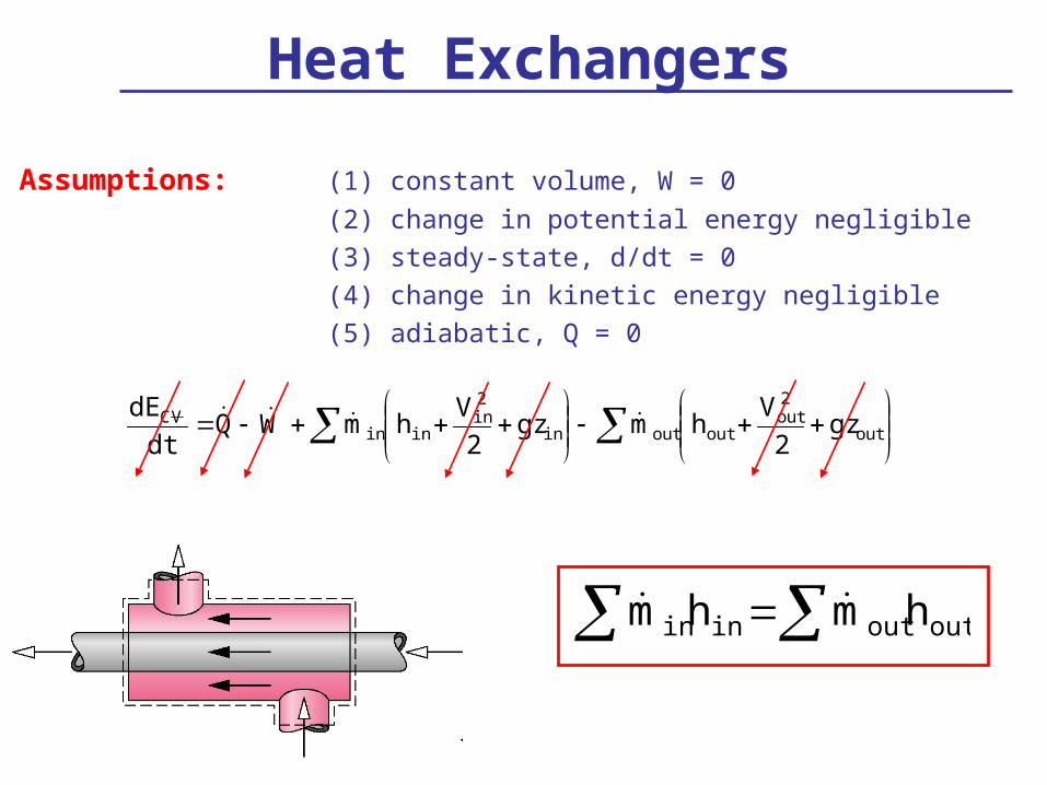
Heat Exchangers
out
2out
outoutin
2in
ininVC gz
2
Vhmgz
2
VhmWQ
dt
dE
Assumptions: (1) constant volume, W = 0
(2) change in potential energy negligible
(3) steady-state, d/dt = 0
(4) change in kinetic energy negligible
(5) adiabatic, Q = 0
outoutinin hmhm
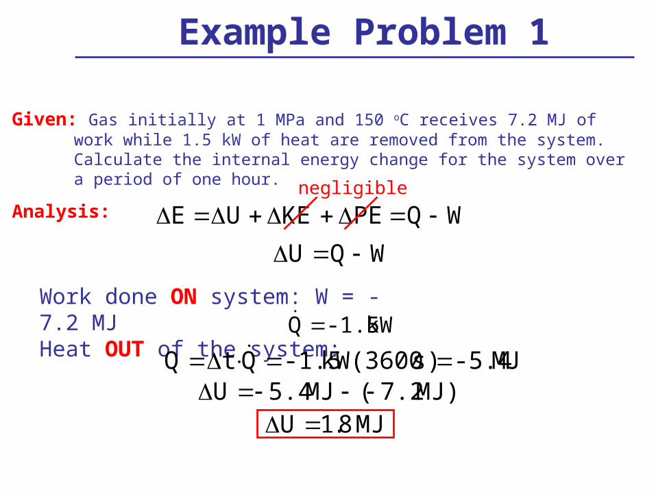
Example Problem 1
Given: Gas initially at 1 MPa and 150 oC receives 7.2 MJ of work while 1.5 kW of heat are removed from the system. Calculate the internal energy change for the system over a period of one hour.
Analysis:
E U KE PE Q Wnegligible
U Q W
Work done ON system: W = -7.2 MJHeat OUT of the system: kW-1.5Q
MJ-5.4s)kW(3600-1.5QtQ
U 5.4 MJ ( 7.2 MJ)
U 1.8 MJ

Example Problem 2
Given: Calculate the power required to compress 10 kg/s of air from 1 atm and 37 oC to 2 atm and 707 oC.For low pressure air: T = 310 K; h = 290.4 kJ/kg
T = 980 K; h = 1023 kJ/kgAnalysis:
out
2out
outoutin
2in
ininVC gz
2
Vhmgz
2
VhmWQ
dt
dE
)h(hmW outin
kgkJ
skg 1023)(290.410W
kW73267326W skJ
Done ON systemkW7326Wc

Example Problem 3
Given: A gas goes through the following thermodynamic cycle.
A to B: constant-temperature compressionB to C: constant-volume cooling
C to A: constant-pressure expansion
The pressure and volume at state C are 1.4 bar and 0.028 m3, respectively. The net work from C to A is 10.5 kJ.
What is the net work from one complete cycle A-B-C?
Analysis:
CA
B
P
V
ACCBBAcyc WWWW
A
C
C
B
B
A
cyc VpdVpdVpdVpdW
V 0

Example Problem 3
CA
B
P
V
kJ10.5VpdVpdWB
A
cyc
A
B
V
VRTlnW
Constant Temperature:
Need volume @ A, constant pressure A to C
W pA V A V C V A V C WCA
pA
J1
mN1m
N1
Pa1
Pa1x10
bar1
bar1.4
J10500m0.028
p
WVV
2
53
A
CACA
Compression, W<0
3A m0.103V

Example Problem 3
CA
B
P
V
kJ10.5kJ18.8Wcyc
A
BBA V
VRTlnW
Constant Temperature:
Ideal gas and constant mass
0.103
0.028ln
mN1
J1m0.103
mPa1
N1
bar1
Pa1x10bar1.4
V
VlnVpW 3
2
5
A
BABA
kJ-18.8W BA
kJ8.3Wcyc

PROPERTIES OF PURE SUBSTANCES
• Use of Steam Tables
• Use of R-134a Tables, NH3 Tables, and P-h Diagrams
• Use of Steam Tables
• Use of R-134a Tables, NH3 Tables, and P-h Diagrams
Pure Substances
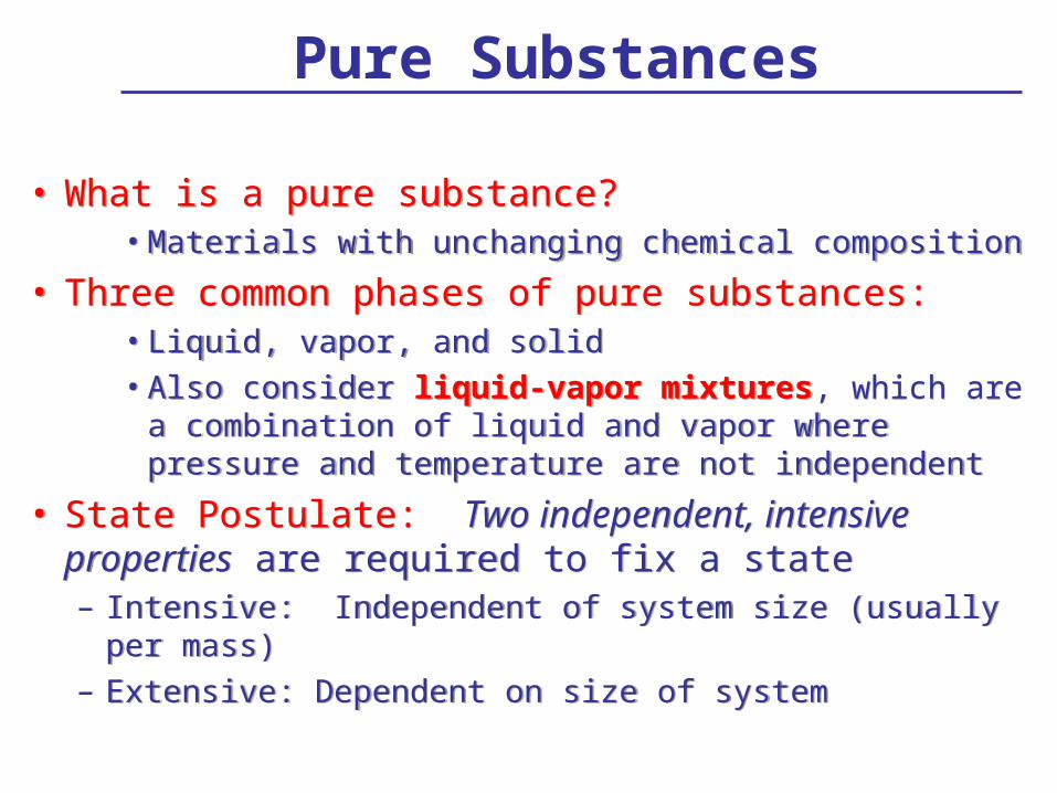
• What is a pure substance?• Materials with unchanging chemical composition
• Three common phases of pure substances: • Liquid, vapor, and solid• Also consider liquid-vapor mixtures, which are a
combination of liquid and vapor where pressure and temperature are not independent
• State Postulate: Two independent, intensive properties are required to fix a state– Intensive: Independent of system size (usually per mass)– Extensive: Dependent on size of system
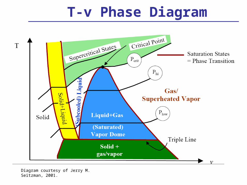
T-v Phase Diagram
Diagram courtesy of Jerry M. Seitzman, 2001.
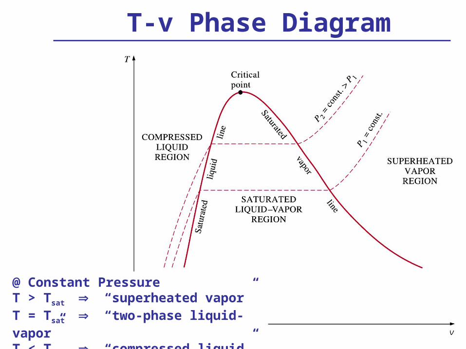
@ Constant PressureT > Tsat “superheated vapor”T = Tsat “two-phase liquid-vapor”T < Tsat “compressed liquid”
T-v Phase Diagram

P-v Phase Diagram
@ Constant TemperatureP < Psat “superheated vapor”P = Psat “two-phase liquid-vapor”P > Psat “compressed liquid”

Common Properties
• Mass, m– Extensive– Units [kg]
• Volume, V – Extensive– Units [m3]
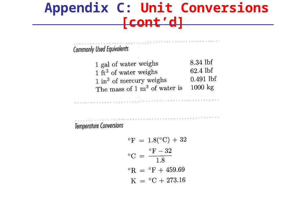
• Pressure, P – Intensive– Absolute units [Pa, psia]– Gage, Pgage = Pabs - Patm
• Temperature, T – Absolute units [K or oR]– T[K] = T[oC] + 273.15– T[oR] = T[oF] + 459.67
• Mass, m– Extensive– Units [kg]
• Volume, V – Extensive– Units [m3]
• Pressure, P – Intensive– Absolute units [Pa, psia]– Gage, Pgage = Pabs - Patm
• Temperature, T – Absolute units [K or oR]– T[K] = T[oC] + 273.15– T[oR] = T[oF] + 459.67
A set of properties that completely describes a system, specifies the state of the system.
• Specific Volume, v – Intensive– Units [m3/kg]– v = 1/ = V/m
• Internal energy, u – Intensive– Units [kJ/kg]– U = m*u [kJ]
• Enthalpy, h – Intensive – Units [kJ/kg]– h = u + Pv; H = U + P V– H = m*h
• Specific Volume, v – Intensive– Units [m3/kg]– v = 1/ = V/m
• Internal energy, u – Intensive– Units [kJ/kg]– U = m*u [kJ]
• Enthalpy, h – Intensive – Units [kJ/kg]– h = u + Pv; H = U + P V– H = m*h

Properties [cont’d]• Entropy, s
– S, extensive [kJ/K]– s, intensive [kJ/kg-K]
• Enthalpy– H, extensive [kJ]– H, intensive [kJ/kg]– H = U + PV – h = u + Pv]
• Gibbs’ Function– G, extensive [kJ]– g, intensive [kJ/kg]– g = h - Ts = u + Pv - Ts – G = H - TS = U + PV – TS
• Entropy, s – S, extensive [kJ/K]– s, intensive [kJ/kg-K]
• Enthalpy– H, extensive [kJ]– H, intensive [kJ/kg]– H = U + PV – h = u + Pv]
• Gibbs’ Function– G, extensive [kJ]– g, intensive [kJ/kg]– g = h - Ts = u + Pv - Ts – G = H - TS = U + PV – TS
s Q rev
T

Saturated Liquid Vapor Mixture (SLVM)
Quality is a functionof the horizontaldistances on P-v
and T-v diagrams
gf
g
vapliq
vap
mm
m
mm
mx
mass of vapor
mass of liquid
fg
fmix
fg
fmix
fg
fmix
fg
fmix
vv
vv
ss
ss
hh
hh
uu
uux
Quality:Quality:
fgfmix
fgfmix
fgffgfmix
fgffgfmix
vvxvv
uuxuu
ssxsxsss
hhxhxhhh
Example
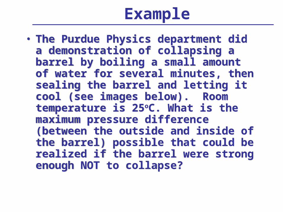
• The Purdue Physics department did a demonstration of collapsing a barrel by boiling a small amount of water for several minutes, then sealing the barrel and letting it cool (see images below). Room temperature is 25oC. What is the maximum pressure difference (between the outside and inside of the barrel) possible that could be realized if the barrel were strong enough NOT to collapse?
• The Purdue Physics department did a demonstration of collapsing a barrel by boiling a small amount of water for several minutes, then sealing the barrel and letting it cool (see images below). Room temperature is 25oC. What is the maximum pressure difference (between the outside and inside of the barrel) possible that could be realized if the barrel were strong enough NOT to collapse?
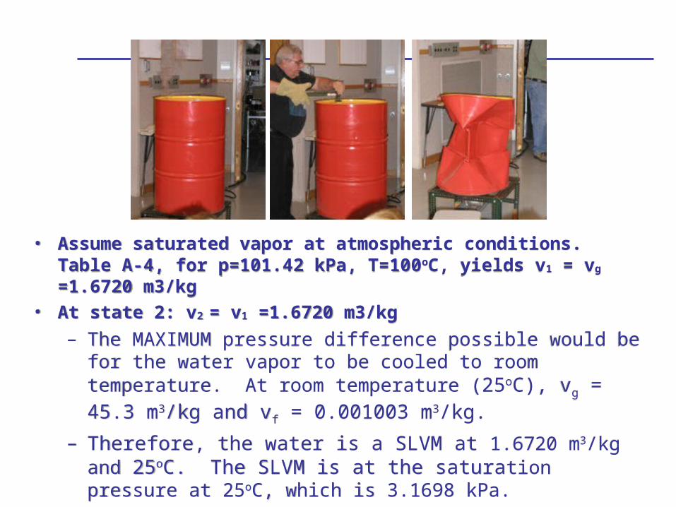
• Assume saturated vapor at atmospheric conditions. Table A-4, for p=101.42 kPa, T=100oC, yields v1 = vg =1.6720 m3/kg
• At state 2: v2 = v1 =1.6720 m3/kg
– The MAXIMUM pressure difference possible would be for the water vapor to be cooled to room temperature. At room temperature (25oC), vg = 45.3 m3/kg and vf = 0.001003 m3/kg.
– Therefore, the water is a SLVM at 1.6720 m3/kg and 25oC. The SLVM is at the saturation pressure at 25oC, which is 3.1698 kPa.
– For this process, ΔP = 101.42 – 3.1698 kPa.• Thus, the maximum pressure difference is 98.25 kPa.

IDEAL GASES
• Equations of State
• Enthalpy and Internal Energy Changes
• Equations of State
• Enthalpy and Internal Energy Changes

Ideal Gas Equation of State
Ru = 8.314 kJ/kmol-K
= 8314 J/kmol-K
= 1.986 cal/mol-K
Ru = 8.314 kJ/kmol-K
= 8314 J/kmol-K
= 1.986 cal/mol-K
mRTVP RTPv
ρRTP TnRVP u
gas
u
MW
RR
P pressure [Pa]
V volume [m3]
m mass [kg]
R gas constant [J/kg-K]
T temperature [K]
density [kg/m3]
v specific volume [m3/kg]
n number of moles [mol]
Ru universal gas constant [J/kmol-K]
MWgas molecular weight [kg/kmol]

Ideal Gas Relationships
Specific Heats:
Entropy:
s cp
T2
T1
R ln
p2
p1
Internal Energy: Enthalpy:
cp – cv = R
constant pressure specific heat [kJ/kg-K]
constant volume specific heat [kJ/kg-K]
gas constant [kJ/kg-K]
u = cvT [kJ/kg] h = cpT [kJ/kg]
s cv
T2
T1
R ln
v2
v1
(Assuming constant
specific heat)
(Assuming constant
specific heat)

Ideal Gas Relationships
2211 vpvp
2
1
2
1
v
v
T
T
Constant Temperature:
Constant Volume:
Constant Pressure:
2
1
2
1
p
p
T
T
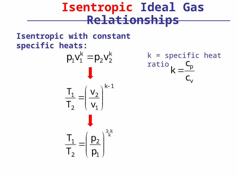
Isentropic Ideal Gas Relationships
k22
k11 vpvp
1k
1
2
2
1
v
v
T
T
Isentropic with constant specific heats:
k = specific heat ratio
kk1
1
2
2
1
p
p
T
T
v
p
c
ck

Non-ideal Gases
• Gases behave ideally at low pressures and high temperatures
• What is meant by low pressure and high temperature?– Compressibility factor quantifies the deviation of
a pure substance from ideal gas behavior at a given temperature and pressure
– Z = 1 (ideal gas)– For a real gas, Z > 1 or Z < 1– For Z very close to unity, we can assume ideal gas
behavior, most of the time
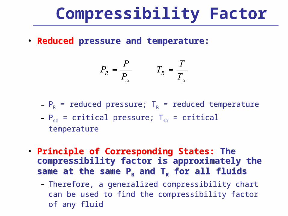
• Reduced pressure and temperature:
– PR = reduced pressure; TR = reduced temperature
– Pcr = critical pressure; Tcr = critical temperature
• Principle of Corresponding States: The compressibility factor is approximately the same at the same PR and TR for all fluids
– Therefore, a generalized compressibility chart can be used to find the compressibility factor of any fluid
Compressibility Factor
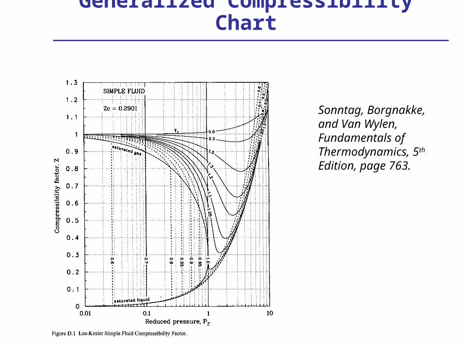
Generalized Compressibility Chart
Sonntag, Borgnakke, and Van Wylen, Fundamentals of Thermodynamics, 5th Edition, page 763.

Property Evaluation
• STEP 1: ALWAYS start in the saturated or “two-phase liquid-vapor” tables
• STEP 2: Identify two, independent, intensive properties– Pick one property and find its location; compare the second using the
following rules:
– If the properties are pressure and temperature, and
• Tsat < T or Psat > P, then “superheated vapor”
• Tsat > T or Psat < P, then “compressed liquid” or “sub-cooled”
• Tsat = T or Psat = P, then “liquid-vapor” and need another property
– If one of the properties is not pressure or temperature
• Let be your property
• > g, then “superheated vapor”
• < f , then “compressed liquid” or “sub-cooled”
• f< < g, then “liquid-vapor”

Property Evaluation
• STEP 3: Evaluate the remaining properties
– If “superheated vapor,” then go to superheated tables
– If “compressed liquid” or “sub-cooled,” then go to compressed liquid tables
• If data does not exist, assume the following:
v = vf h = hf
u = uf s = sf
where the saturated liquid property is evaluated at the given temperature since pressure does not impact liquids that much
– If “liquid-vapor,” then continue using the “two-phase liquid-vapor” tables and find quality

Saturated Mixture Table

Superheated Steam

Superheated Steam [cont’d]

Mollier Diagram (P vs h)
Example 1
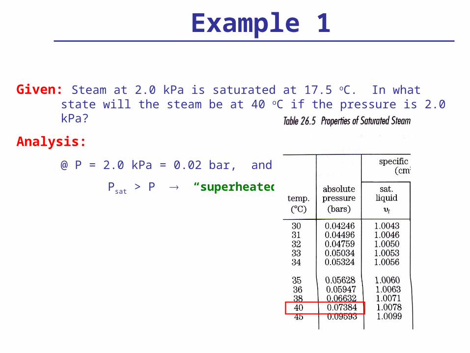
Given: Steam at 2.0 kPa is saturated at 17.5 oC. In what state will the steam be at 40 oC if the pressure is 2.0 kPa?
Analysis:
@ P = 2.0 kPa = 0.02 bar, and T = 40oC
Psat > P “superheated vapor”
Example 2
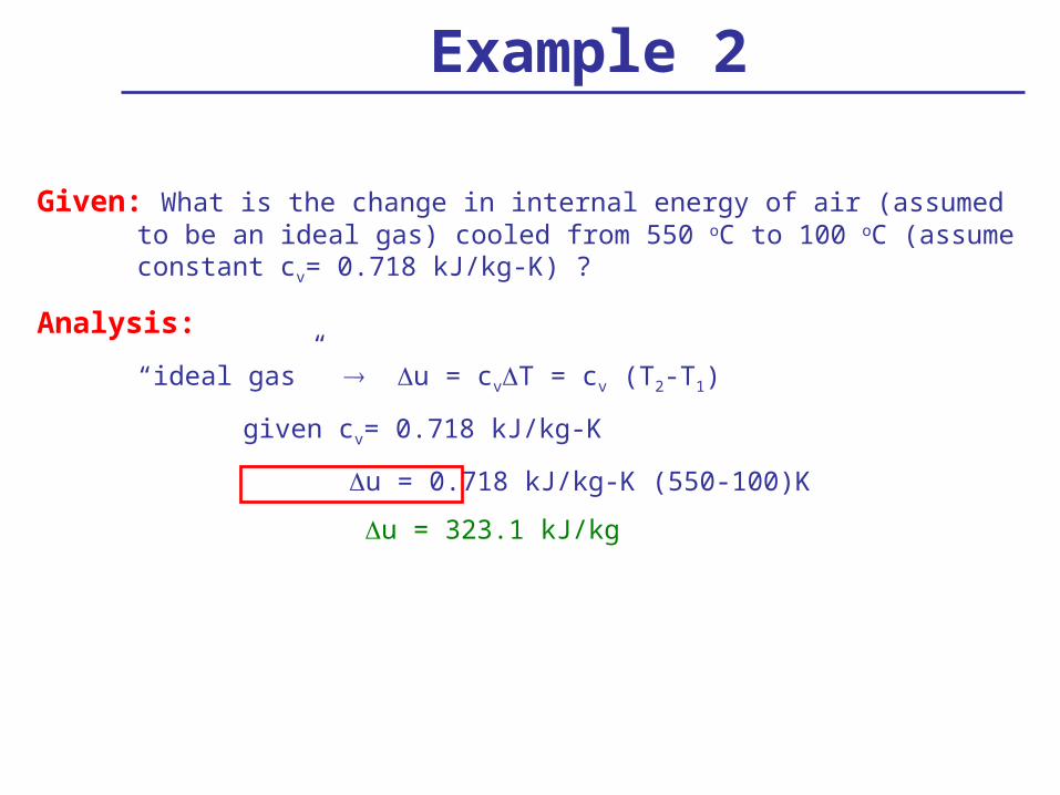
Given: What is the change in internal energy of air (assumed to be an ideal gas) cooled from 550 oC to 100 oC (assume constant cv= 0.718 kJ/kg-K) ?
Analysis:
“ideal gas” u = cvT = cv (T2-T1)
given cv= 0.718 kJ/kg-K
u = 0.718 kJ/kg-K (550-100)K
u = 323.1 kJ/kg
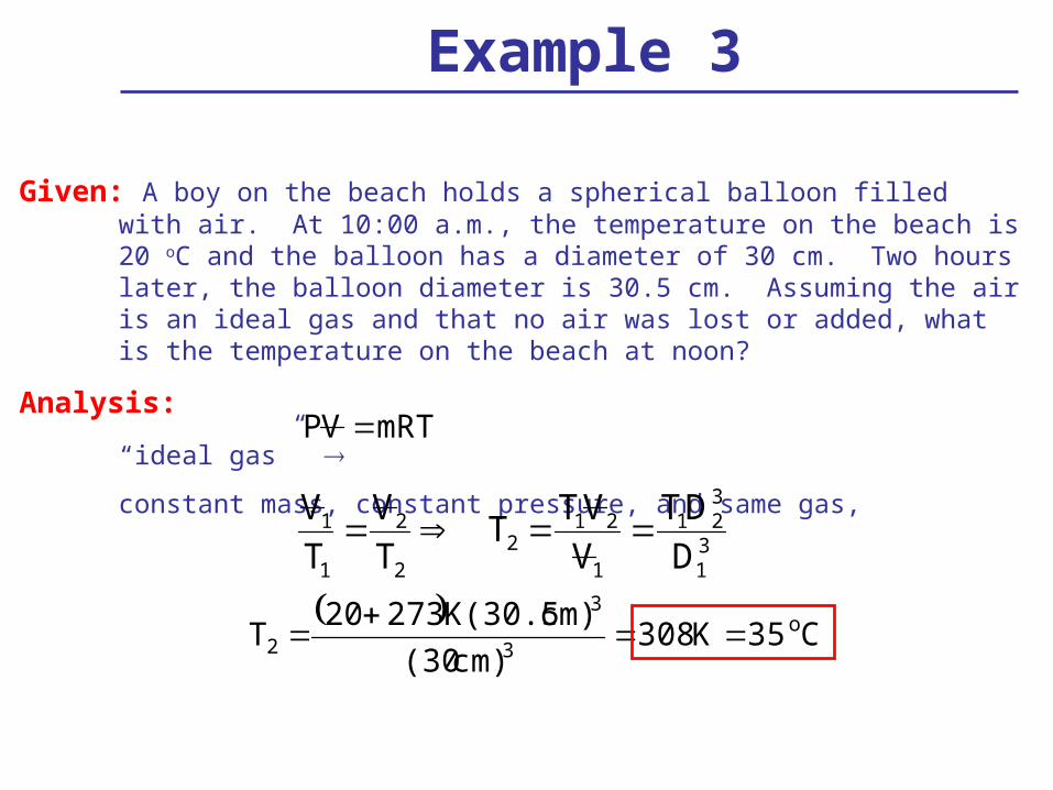
Example 3
Given: A boy on the beach holds a spherical balloon filled with air. At 10:00 a.m., the temperature on the beach is 20 oC and the balloon has a diameter of 30 cm. Two hours later, the balloon diameter is 30.5 cm. Assuming the air is an ideal gas and that no air was lost or added, what is the temperature on the beach at noon?
Analysis:
“ideal gas”
constant mass, constant pressure, and same gas,
mRTVP
V 1T1
V 2T2
T2 T1V 2V 1
T1D2
3
D13
C35K308
cm)(30
cm)K(30.527320T o
3
3
2

Example 4
Given: Steam initially at 1 MPa and 200 oC expands in a turbine to 40 oC and 83% quality. What is the change in entropy?
Analysis:
@ P1=1 MPa = 10 bar, and T1=200 oC >> Psat > P “superheated vapor”
@ T=40 oC and x2 = 0.83 “two-phase liquid-vapor”
Example 4 - Cont’d
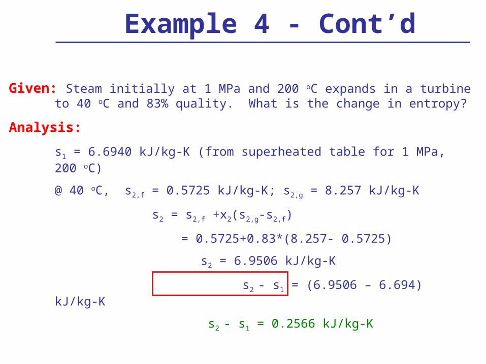
Given: Steam initially at 1 MPa and 200 oC expands in a turbine to 40 oC and 83% quality. What is the change in entropy?
Analysis:
s1 = 6.6940 kJ/kg-K (from superheated table for 1 MPa, 200 oC)
@ 40 oC, s2,f = 0.5725 kJ/kg-K; s2,g = 8.257 kJ/kg-K
s2 = s2,f +x2(s2,g-s2,f)
= 0.5725+0.83*(8.257- 0.5725)
s2 = 6.9506 kJ/kg-K
s2 - s1 = (6.9506 – 6.694) kJ/kg-K
s2 - s1 = 0.2566 kJ/kg-K

Example 5
Given: A 3 kg mixture of water and water vapor at 70 oC is held at constant pressure while heat is added. The enthalpy of the water increases by 50 kJ/kg. What is the change in entropy?
Analysis:
s = 0.1458 kJ/kg-K
s Q rev
T s
Q
To
50 kJ/kg
(70 273)K
integrate
Heat flow = enthalpy change since
Q H

kk1
1
2
2
1
p
p
T
T
Given: Through an isentropic process, a piston compresses 2 kg of an ideal gas at 150 kPa and 35 oC in a cylinder to a pressure of 300 kPa. The specific heat of the gas for constant pressure processes is 5 kJ/kg-K; for constant volume processes, the specific heat is 3 kJ/kg-K. What is the final temperature of the gas?
Analysis:
“ideal gas and constant entropy”
cp = 5 kJ/kg-K; cv = 3 kJ/kg-K
Example 6
667.13
5
c
ck
v
p
kk-1
1
2
12
p
p
TT
C133.44K406.44
150300
K27335T o
21.6671.667-1
Example 7
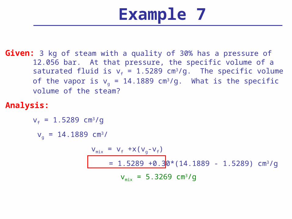
Given: 3 kg of steam with a quality of 30% has a pressure of 12.056 bar. At that pressure, the specific volume of a saturated fluid is vf = 1.5289 cm3/g. The specific volume of the vapor is vg = 14.1889 cm3/g. What is the specific volume of the steam?
Analysis:
vf = 1.5289 cm3/g
vg = 14.1889 cm3/
vmix = vf +x(vg-vf)
= 1.5289 +0.30*(14.1889 - 1.5289) cm3/g
vmix = 5.3269 cm3/g

Second Law
• THE SECOND LAW OF THERMODYNAMICS
• ENTROPY
• THE SECOND LAW OF THERMODYNAMICS
• ENTROPY
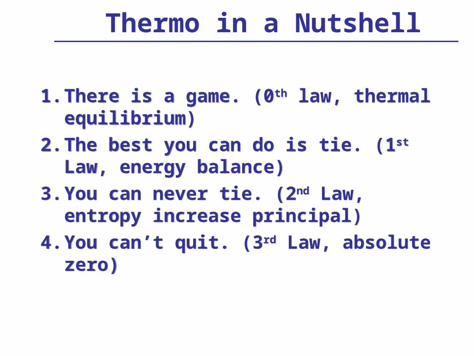
Thermo in a Nutshell
1. There is a game. (0th law, thermal equilibrium)
2. The best you can do is tie. (1st Law, energy balance)
3. You can never tie. (2nd Law, entropy increase principal)
4. You can’t quit. (3rd Law, absolute zero)
1. There is a game. (0th law, thermal equilibrium)
2. The best you can do is tie. (1st Law, energy balance)
3. You can never tie. (2nd Law, entropy increase principal)
4. You can’t quit. (3rd Law, absolute zero)
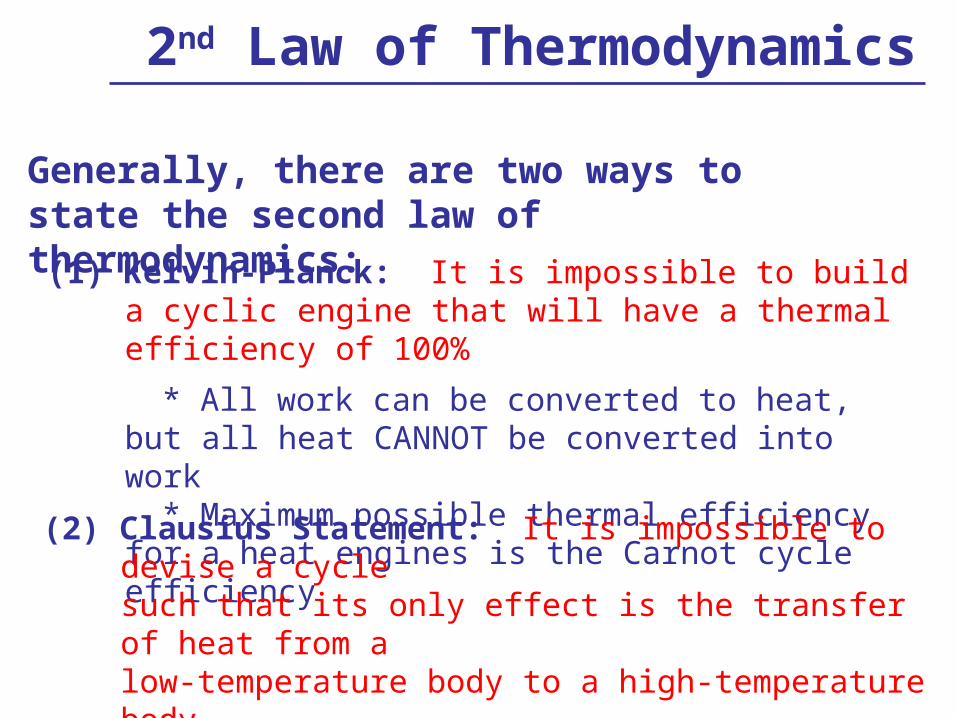
2nd Law of Thermodynamics
(1) Kelvin-Planck: It is impossible to build a cyclic engine that will have a thermal efficiency of 100%
* All work can be converted to heat, but all heat CANNOT be converted into work
* Maximum possible thermal efficiency for a heat engines is the Carnot cycle efficiency
(2) Clausius Statement: It is impossible to devise a cycle such that its only effect is the transfer of heat from a low-temperature body to a high-temperature body
* An input of work is always required for refrigeration cycles
Generally, there are two ways to state the second law of thermodynamics:

Net entropy must ALWAYS increase:
• The equality applies for reversible processes
• The inequality applies for irreversible processes, in which entropy production contributes to entropy change
Entropy Changes
2
1
T
T T
dQS
For a constant temperature, reversible process, entropy change is given by:
S S2 S1 Q
To
discharging energy to reservoir
temperature of the reservoir
Isentropic process, entropy change is given by:
S S2 S1 0
Adiabatic process, entropy change is given by:
S S2 S1 0
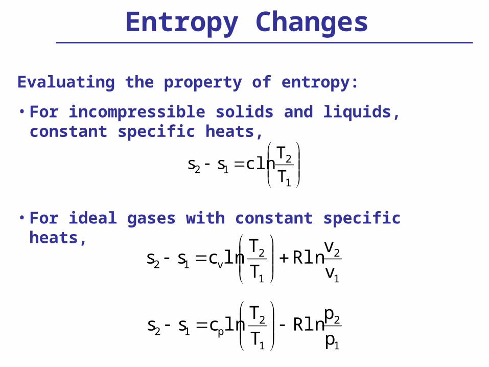
Entropy Changes
Evaluating the property of entropy:
• For incompressible solids and liquids, constant specific heats,
• For ideal gases with constant specific heats,
1
212 T
Tclnss
1
2
1
2v12 v
vRln
T
Tlncss
1
2
1
2p12 p
pRln
T
Tlncss

Problem 4
Given: 1 kg of steam is initially at 400 oC and 800 kPa. The steam expands adiabatically to 200 oC and 400 kPa in a closed process, performing 450 kJ of work, given the following information. Which law does this process violate: (zeroth law, first law, second law, first and second law)?
at 400 oC and 800 kPa at 200 oC and 400 kPa u = 2959.7 kJ/kg u = 2646.8 kJ/kg h = 3267.1 kJ/kg h = 2860.5 kJ/kg s = 7.5716 kJ/kg-K s = 7.1706 kJ/kg
Analysis:
(1) Zeroth law not applicable, does not deal with thermal equilibrium
(2) Check first law
E U KE PE Q Wnegligible

Problem 4 Cont’dat 400 oC and 800 kPa at 200 oC and
400 kPa u = 2959.7 kJ/kg u = 2646.8 kJ/kg h = 3267.1 kJ/kg h = 2860.5 kJ/kg s = 7.5716 kJ/kg-K s = 7.1706 kJ/kg
U Q W
u Q
m W
m Q
mu W
m
kgkJ
kgkJ
kgkJ 4502959.72646.8
m
Q
W > 0 done BY system
kgkJ1.137
m
Q 0
NOT adiabatic Q = 0, as stated
Therefore, violates 1st Law

Problem 4 Cont’dat 400 oC and 800 kPa at 200 oC and
400 kPa s = 7.5716 kJ/kg-K s = 7.1706 kJ/kg
s 0 for adiabatic process
s 7.1706 kJkg-K 7.5716 kJ
kg-K
< 0
violates 2nd Law
(3) Check 2nd Law
s -0.401 kJkg-K
Violates both 1st and 2nd Laws

CYCLES
• Rankine Cycle (Steam)
• Vapor Compression Cycle (Refrigeration)
• Otto Cycle (Gasoline Engine)
• Rankine Cycle (Steam)
• Vapor Compression Cycle (Refrigeration)
• Otto Cycle (Gasoline Engine)
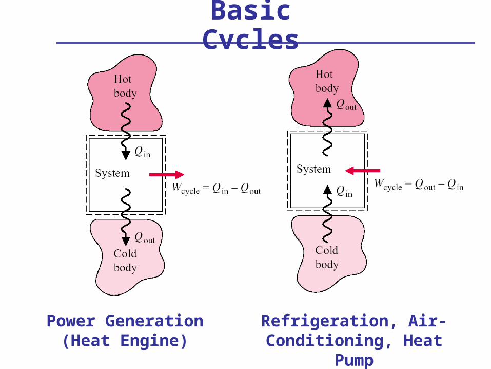
Basic Cycles
Power Generation(Heat Engine)
Refrigeration, Air-Conditioning, Heat Pump
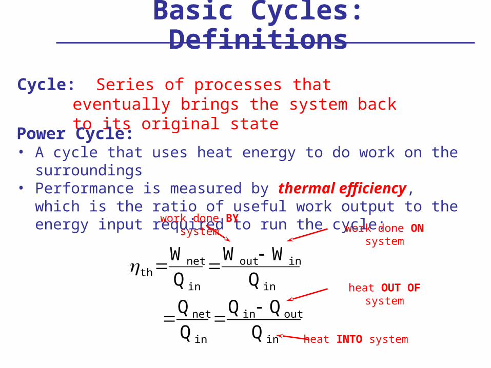
Basic Cycles: Definitions
Cycle: Series of processes that eventually brings the system back to its original state
Power Cycle:• A cycle that uses heat energy to do work on the surroundings• Performance is measured by thermal efficiency, which is the
ratio of useful work output to the energy input required to run the cycle:
th Wnet
Q in
Wout Win
Q in
Qnet
Q in
Q in Qout
Q in
work done ON systemwork done BY system
heat INTO system
heat OUT OF system

Carnot Cycle
Carnot Cycle:
(1) Theoretical implementation of a cycle without any irreversibilities
(2) Work output is the maximum possible for any heat engine due to reversible processes
ProcessesA to B: isothermal expansion of saturated liquid to saturated vapor
B to C: isentropic expansion of vapor (Q = 0; s = 0)
C to D: isothermal compression of vapor
D to A: isentropic compression of vapor (Q = 0; s = 0)
B
CD
A

Carnot: P-v and T-s Diagrams
A
D C
BA
B
D C
Carnot Efficiency:
th,Carnot TH TL
TH
1TL
TH
cold reservoir temperature
hot reservoir temperature

Problem 1
Given: A Carnot engine receives 100 kJ of heat from a hot reservoir at 370 oC and rejects 37 kJ of heat. Determine the temperature of the cold reservoir.
Analysis:
kJ100
kJ37kJ100
Q
Q
Q
H
LH
in
netth
th,Carnot TH TL
TH
1TL
TH
th 0.63 or 63%
TL TH TH th,Carnot
0.63273370)273370(TL
TL = 237.91 K = -35.09 oC
Use absolute temperatures!
QHQH
QLQL
WW
TLTL
THTH

Problem 2
Given: What is the maximum thermal efficiency possible for a power cycle operating between 600 oC and 110 oC?
Analysis:
th,Carnot 1TL
TH
Carnot yields maximum possible efficiency
th,Carnot 1110 273 K600 273 K
th,Carnot 0.561 or 56.1%
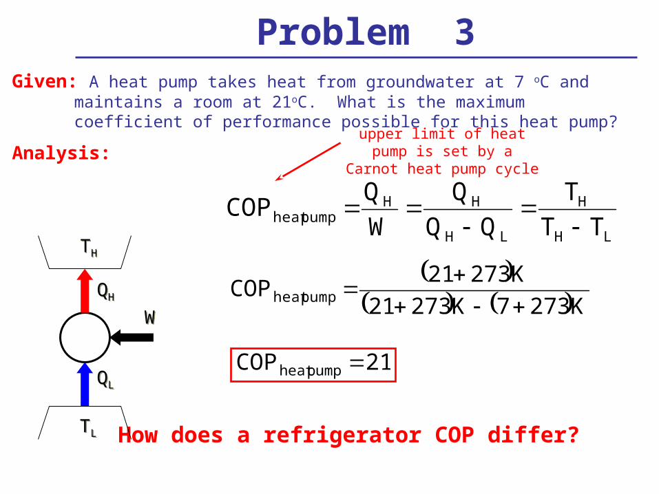
Problem 3Given: A heat pump takes heat from groundwater at 7 oC and maintains a room at
21oC. What is the maximum coefficient of performance possible for this heat pump?
Analysis:
LH
H
LH
HHpumpheat TT
T
Q
W
QCOP
upper limit of heat pump is set by a Carnot heat pump cycle
K2737K27321
K27321COP pumpheat
21COP pumpheat
How does a refrigerator COP differ?
QHQH
QLQL
WW
TLTL
THTH

Rankine CycleRankine Cycle: • Vapor-power cycle commonly used
in power plants with water as the working fluid
• Efficiency is ratio of useful output to required input:
Processes1 to 2: Isentropic expansion of the working fluid through the turbine from saturated
vapor at state 1 to the condenser pressure (Q = 0; s = 0)2 to 3: Heat transfer from the working fluid as it flows at constant pressure through
the condenser with saturated liquid at state 33 to 4: Isentropic compression in the pump to state 4 in the compressed liquid
region. (Q = 0; s = 0)4 to 1: Heat transfer to the working fluid as it flows at constant pressure through the
boiler to complete the cycle
41
3421
in
netth hh
hhhh
Q
W
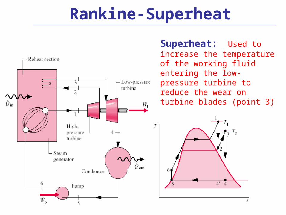
Rankine-Superheat
Superheat: Used to increase the temperature of the working fluid entering the low-pressure turbine to reduce the wear on turbine blades (point 3)

Combustion Power Cycles
• Differ from vapor cycles since they cannot return to their initial conditions
• Due to significant complexities with computing mixtures of fuel and air, combustion power cycles are often analyzed as air-standard cycles– Air-Standard Otto Cycle: Hypothetical closed system
using air as the working fluid to simplify the chemistry due to combustion

Air-Standard Otto CycleAir-Standard Otto Cycle: Hypothetical closed system using air as the working fluid to simplify the chemistry due to combustion
Processes1 to 2: Isentropic compression of the working fluid (Q = 0; s = 0)2 to 3: Constant volume heat addition3 to 4: Isentropic expansion of the working fluid (Q = 0; s = 0)4 to 1: Constant volume heat rejection
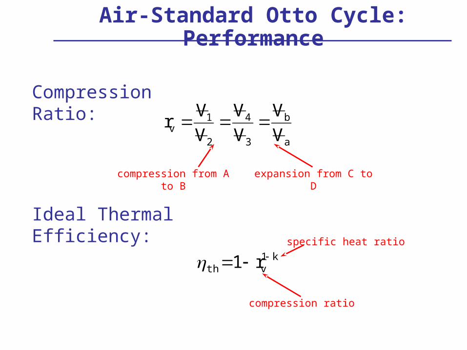
Air-Standard Otto Cycle: Performance
Ideal Thermal Efficiency:
rv V 1V 2
V 4V 3
V bV a
Compression Ratio:
th 1 rv1 k
compression from A to B expansion from C to D
compression ratio
specific heat ratio

Refrigeration Cycles
• In refrigeration cycles, heat is transferred from a low-temperature area (i.e. inside the refrigerator) to a high-temperature area (e.g., in the kitchen)• Since heat spontaneously flows only from high to low
temperature areas, work is required to force heat transfer• Opposite of heat engines
• Systems:• Refrigerator: Heat is removed from air inside• Air conditioner: Heat is removed from air in an occupied
space• Heat Pump: Heat is supplied to air in an occupied space• Chiller: Heat is removed from water

Refrigeration Cycles: Performance
• In refrigeration cycles, the coefficient of performance (COP) is used in place of thermal efficiency to measure performance
• The COP is always the ratio of useful energy transfer to the work input
W
QCOP
W
QCOP
Hpumpheat
LACor,refrigerat
heat transfer from low-temperature reservoir
work input
heat transfer from high-temperature reservoir

MISCELLANEOUS
• Mixture of Gases
• Heat Transfer – Conduction
– Convection
– Radiation
• Mixture of Gases
• Heat Transfer – Conduction
– Convection
– Radiation

Modes of Heat Transfer
• All heat transfer driven by temperature difference
• Heat transfer occurs via 3 modes– conduction (solid/fluid; molecular
collision)• depends on temperature gradient
– convection (fluid; motion)• depends on temperature difference
– radiation (no medium needed – electromagnetic waves)• depends on T4
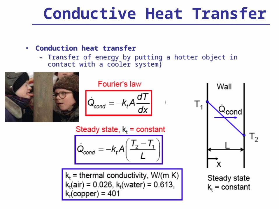
Conductive Heat Transfer
• Conduction heat transfer– Transfer of energy by putting a hotter object in contact with a cooler
system)
• Conduction heat transfer– Transfer of energy by putting a hotter object in contact with a cooler
system)

Convective Heat Transfer• Convection heat transfer
– transfer of energy between a solid surface and a moving fluid
• Convection heat transfer – transfer of energy between a solid surface and a moving fluid
Newton’s law of cooling,h = heat transfer coefficient.

Convective Heat Transfer
• The “wind chill” factor is an example
• The air flow makes a given temperature “feel” (higher heat loss) like a lower temperature
• The “wind chill” factor is an example
• The air flow makes a given temperature “feel” (higher heat loss) like a lower temperature
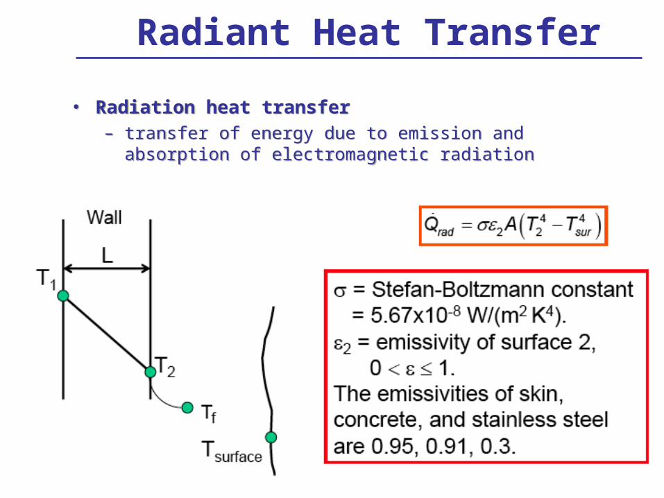
Radiant Heat Transfer
• Radiation heat transfer – transfer of energy due to emission and absorption of
electromagnetic radiation
• Radiation heat transfer – transfer of energy due to emission and absorption of
electromagnetic radiation

Comfort in a Room
• At the same air temperature in a room in a house it “feels” cooler in the winter than the summer– Why?
• At the same air temperature in a room in a house it “feels” cooler in the winter than the summer– Why?

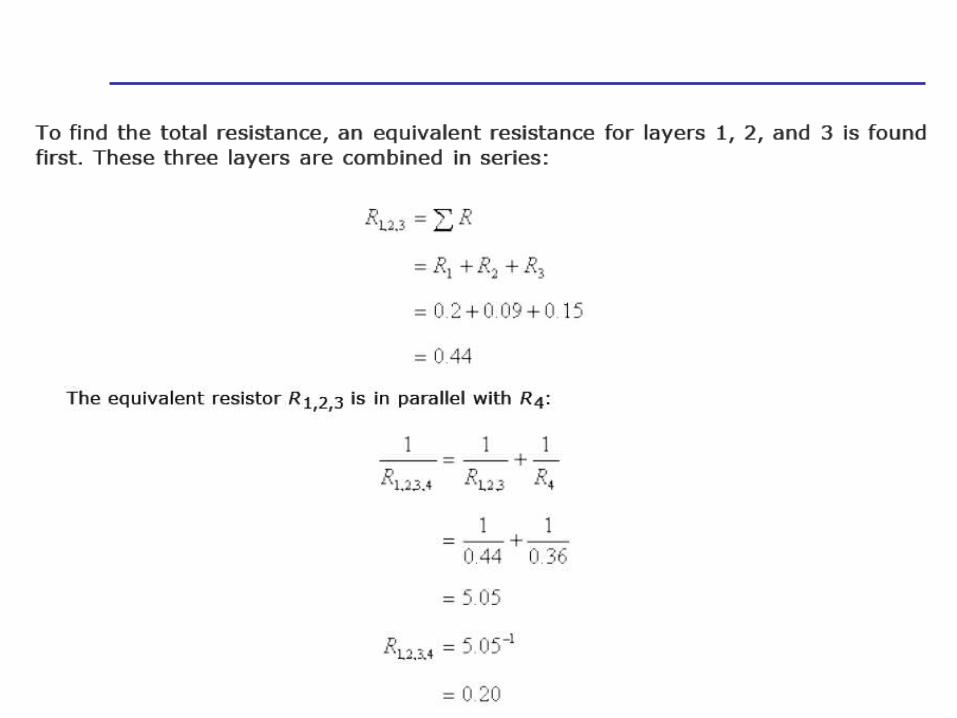
Thermal Circuit Model
• A model used often to calculate the heat transfer through a 1-D system is called the thermal circuit model
• In this model, each layer is replaced by an equivalent resistor called the thermal resistance– For conduction,
– For convection,
• A model used often to calculate the heat transfer through a 1-D system is called the thermal circuit model
• In this model, each layer is replaced by an equivalent resistor called the thermal resistance– For conduction,
– For convection,


Mass and Mole Fraction
Mass Fraction: ratio of component’s mass to the total mass of the mixture
Mole Fraction: ratio of component’s moles to the total moles of the mixture
tot
ii m
mw
mass fraction of ith species
mass of ith species
total mass of mixture
imm 1w i
tot
iii N
Nxy
mole fraction of ith species
moles of ith species
total moles of mixture
1yi
gas-phase liquid-phase
1x i
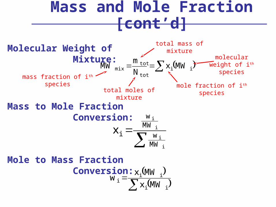
Molecular Weight of Mixture:
Mass to Mole Fraction Conversion:
iitot
totmix MWx
N
mMW
mass fraction of ith species
molecular weight of ith species
total moles of mixture
total mass of mixture
mole fraction of ith species
i
i
i
i
MWw
MWw
ix
Mole to Mass Fraction Conversion:
ii
iii
MWx
MWxw
Mass and Mole Fraction [cont’d]

Amagat’s Law: total volume is the sum of partial volumes
pxV
TRmp i
iii partial pressure
of ith species
total pressure of mixture
mole fraction of ith species
iVV
V
V
p
px ii
i
Non-Reacting Ideal Gases
mass of ith speciesPartial Pressure:
p
TRmV ii
i partial volume of ith species
Partial Volume:
Mole Fraction:
iiuwu
assume adiabatic and reversible
iisws
internal energy entropy
mass fraction
iihwh
enthalpy

The End
AppendicesA: SI PrefixesB: ConstantsC: Unit Conversions

Appendix A: SI Prefixes

Appendix B: Constants
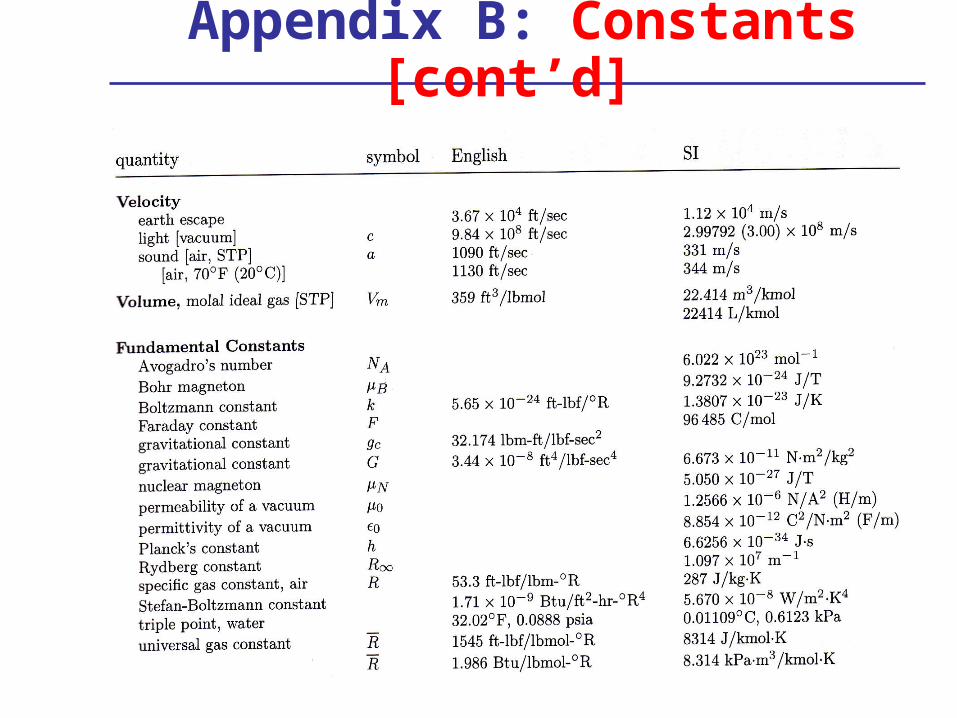
Appendix B: Constants [cont’d]

Appendix C: Unit Conversions
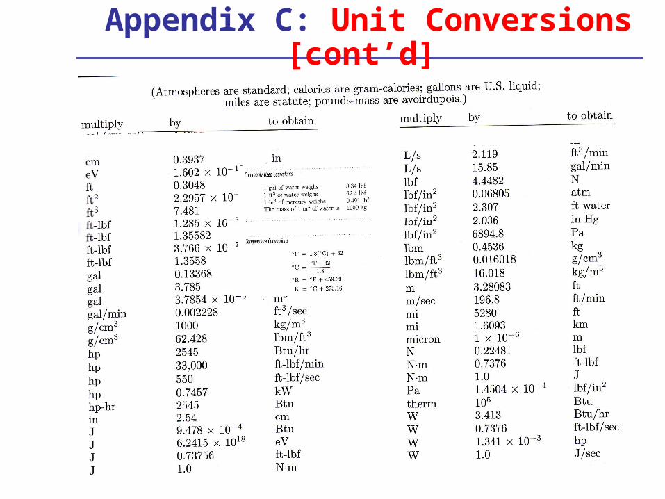
Appendix C: Unit Conversions [cont’d]
Appendix C: Unit Conversions [cont’d]

Extra Examples

Liquid/Vapor Tables & Charts

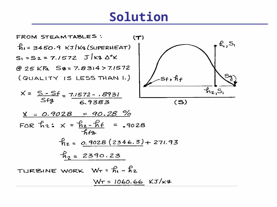
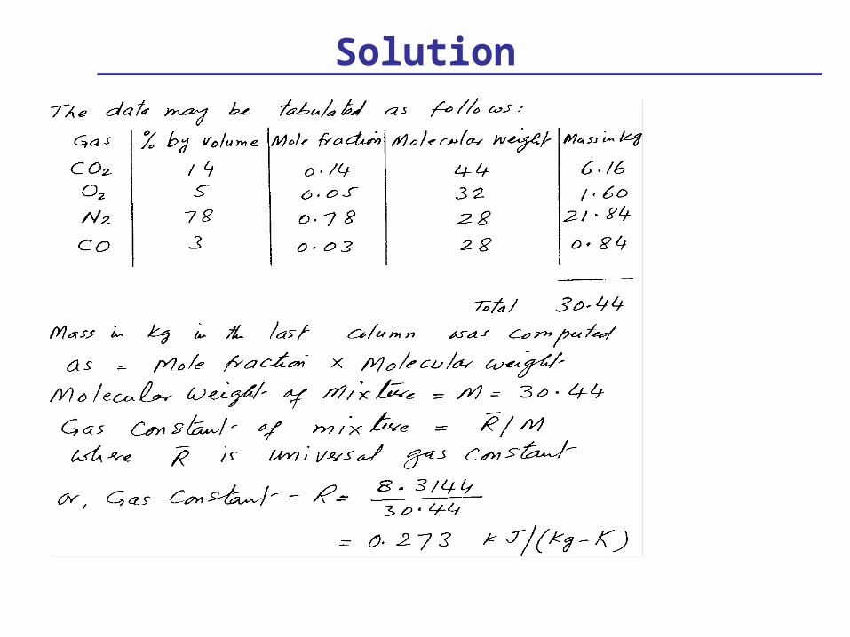
Solution

Solution (continued)

Liquid/Vapor Tables & Charts

Solution
Solution (continued)

Enthalpy

Solution

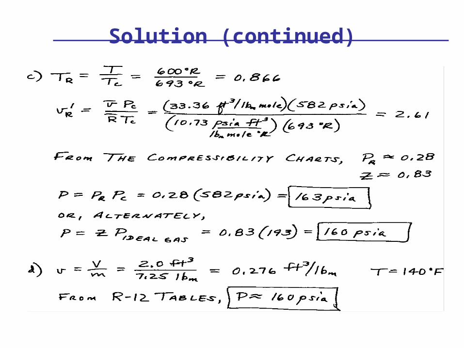
Solution (continued)
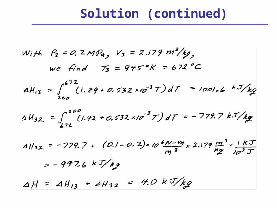
Solution (continued)

Closed Systems

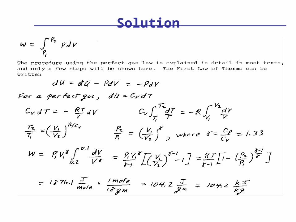
Solution

Steady Flow/Steady State

Solution

Reversible Processes
Solution

Solution (continued)

Reversible Processes
Solution

Three-Process Cycles

Solution

Solution (continued)
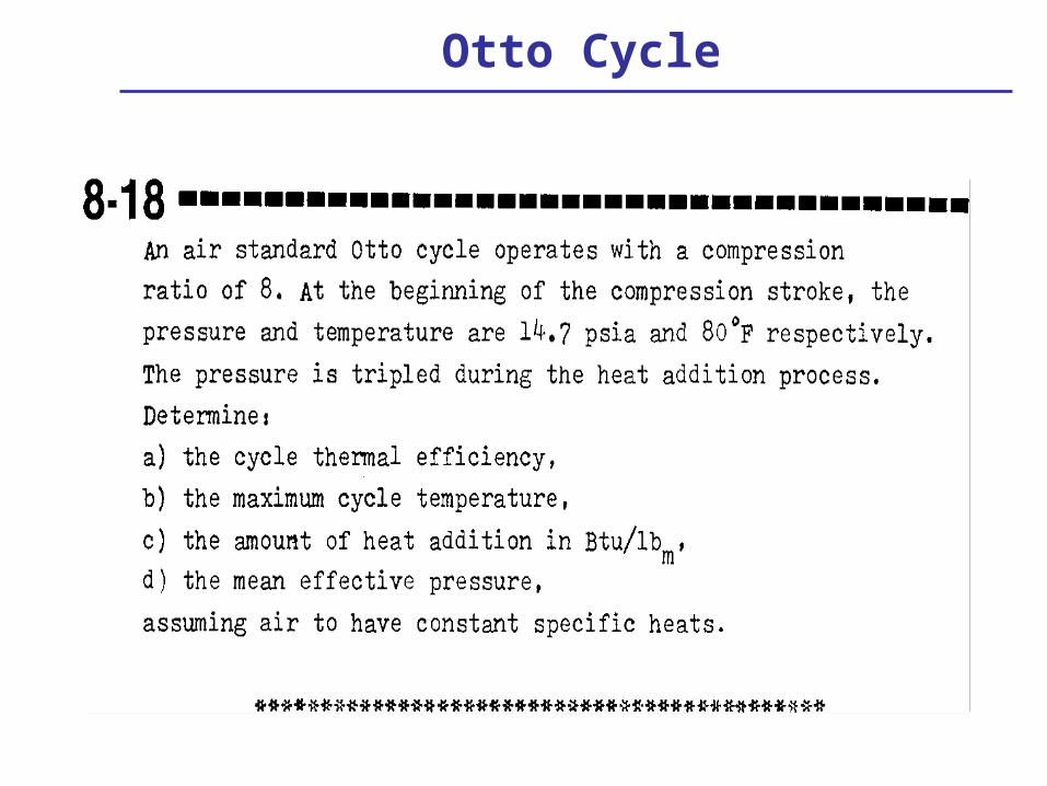
Otto Cycle

Solution

Solution (continued)

Solution (continued)

Reverse Cycles
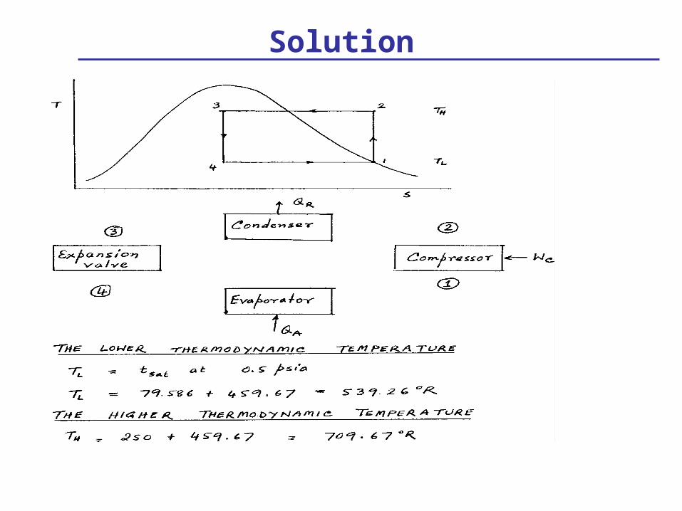
Solution

Solution (continued)
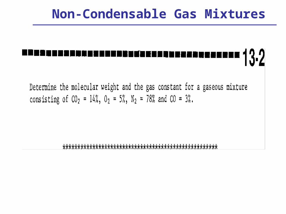
Non-Condensable Gas Mixtures
Solution