thermoelectric air conditioning system using solar cells · thermoelectric air conditioning system...
TRANSCRIPT

International Journal of Scientific & Engineering Research, Volume 8, Issue 1, January-2017 2107 ISSN 2229-5518
IJSER © 2017 http://www.ijser.org
Thermoelectric air conditioning system using solar cells
M. G. Mousa*, A.A.Hegazi* and I. A. Hany**
*Mechanical Power Engineering Dept., Faculty of Engineering, Mansoura University, Mansoura, Egypt Mechanical Engineer at roads and Transportation Directorate, Dakahlia Governorate
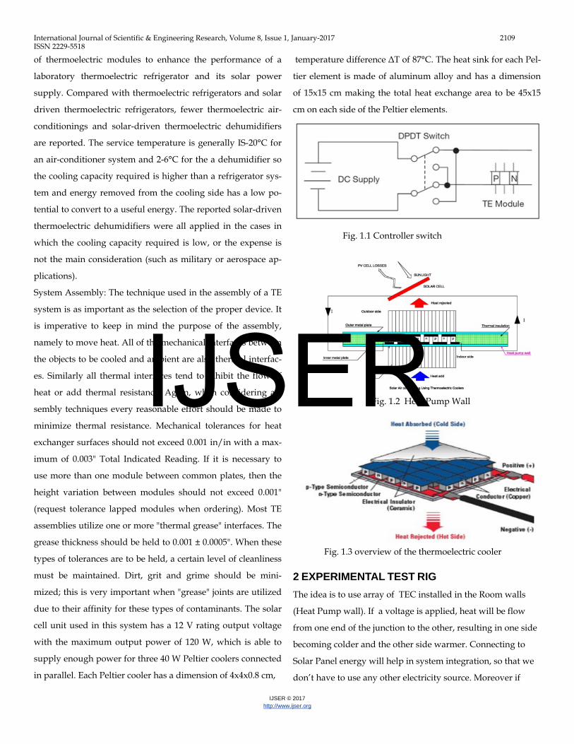
Abstract— This Study is investigated the possibility of heating and cooling air by connecting thermoelectric Elements to a PV panel. The idea is to
reverse the direction of heat flow in Room wall. In hot season the cold side for thermoelectric element will be inside the room and the hot side will be
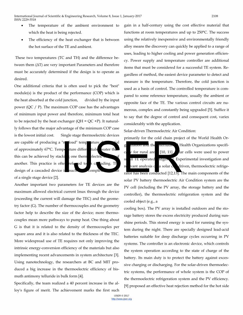
outside the room and vise versa in winter, hot side will be inside the room and cold side will be outside the room, using switch as shown in fig. 1 .A rela-
tively new method to reverse heat transmission through wall is to use thermoelectric (TE) devices when two dissimilar materials form a junction. If a
voltage is applied, heat will flow from one end of the junction to the other, resulting in one side becoming colder (inside the room) and the other side
warmer (outside the room) this will be for summer season, but in winter season warmer (inside the room) and the other side colder (outside the room) .
Connecting to Solar Panel energy will help in system integration, so that we don’t have to use any other electricity source. Moreover if charging system
has been applied, cooling and heating will be possible in the absence of sun. Also extra power can be used for other purposes.
Index Terms— solar Air Conditioning Heat Pump wall Solar cells Thermoelectric paperrevers heat direction solar cells with thermoelectric clooerforced and natural cooling for thermoelectric.
—————————— ——————————
1 INTRODUCTION LITERATURE REVIEW
HERMOELECTRIC coolers are heat pumps solid state
devices without any moving parts, fluids or any gasses.
The basic laws of thermodynamics apply to these devices just
as they do to conventional heat pumps, absorption refrigera-
tors and other devices involving the transfer of heat energy.
TEC couples are made from two elements of semiconductor,
primarily Bismuth Telluride, heavily doped to create either an
excess (n-type) or deficiency (p-type) of electrons. When heat
absorbed at the cold junction it will be pumped to the hot
junction at a rate proportional to current passing through the
circuit and the number of couples. A conventional cooling
system contains three fundamental parts-the evaporator, com-
pressor and condenser. At the cold junction, energy (heat) is
absorbed by electrons as they pass from a low energy level in
the p-type semiconductor element, to a higher energy level in
the n-type semiconductor element, so that the energy required
to move the electrons through the system. At the hot junction,
energy is expelled to a heat sink as electrons move from a high
energy level element (n-type) to a lower energy level element
(p-type).
Parameters Required for Device Selection: In practical use,
couples are combined in a module where they are connected
electrically in series and thermally in parallel. Modules are
available in a great variety of sizes, shape operating Current,
operating voltages and ranges of heat pumping capacity. The
present trend, however, is toward a larger number of couples
operating at lower currents. Three specific system parameters
must be determined before device selection can begin. These
are:
• TC Cold Surface Temperature
• TH Hot Surface Temperature
• QC The amount of heat to be absorbed at the Cold
Surface of the TE.
Generally, if the object to be cooled is in direct intimate
contact with the cold surface of the thermoelectric, the desired
temperature of the object can be considered the temperature of
the cold surface of the TE (TC).
The hot surface temperature TH is defined by two major
parameters:
•
T IJSER
International Journal of Scientific & Engineering Research, Volume 8, Issue 1, January-2017 2108 ISSN 2229-5518
IJSER © 2017 http://www.ijser.org
• The temperature of the ambient environment to
which the heat is being rejected.
• The efficiency of the heat exchanger that is between
the hot surface of the TE and ambient.
These two temperatures (TC and TH) and the difference be-
tween them (ΔT) are very important Parameters and therefore
must be accurately determined if the design is to operate as
desired.
One additional criteria that is often used to pick the "best"
module(s) is the product of the performance (COP) which is
the heat absorbed at the cold junction, divided by the input
power (QC / P). The maximum COP case has the advantages
of minimum input power and therefore, minimum total heat
to be rejected by the heat exchanger (QH = QC +P). It natural-
ly follows that the major advantage of the minimum COP case
is the lowest initial cost. Single stage thermoelectric devices
are capable of producing a "no load" temperature differential
of approximately 67°C. Temperature differentials greater than
this can be achieved by stacking one thermoelectric on top of
another. This practice is often referred to as cascading. The
design of a cascaded device is much more complex than that
of a single stage device [2].
Another important two parameters for TE devices are the
maximum allowed electrical current Imax through the device
(exceeding the current will damage the TEC) and the geome-
try factor (G). The number of thermocouples and the geometry
factor help to describe the size of the device; more thermo-
couples mean more pathways to pump heat. One thing about
G is that it is related to the density of thermocouples per
square area and it is also related to the thickness of the TEC.
More widespread use of TE requires not only improving the
intrinsic energy-conversion efficiency of the materials but also
implementing recent advancements in system architecture [3].
Using nanotechnology, the researchers at BC and MIT pro-
duced a big increase in the thermoelectric efficiency of bis-
muth antimony telluride in bulk form [4].
Specifically, the team realized a 40 percent increase in the al-
loy's figure of merit. The achievement marks the first such
gain in a half-century using the cost effective material that
functions at room temperatures and up to 250°C. The success
using the relatively inexpensive and environmentally friendly
alloy means the discovery can quickly be applied to a range of
uses, leading to higher cooling and power generation efficien-
cy. Power supply and temperature controller are additional
items that must be considered for a successful TE system. Re-
gardless of method, the easiest device parameter to detect and
measure is the temperature. Therefore, the cold junction is
used as a basis of control. The controlled temperature is com-
pared to some reference temperature, usually the ambient or
opposite face of the TE. The various control circuits are nu-
merous, complex and constantly being upgraded [5]. Suffice it
to say that the degree of control and consequent cost, varies
considerably with the application.
Solar-driven Thermoelectric Air Condition:
primarily for the cold chain project of the World Health Or-
ganization and the international Health Organizations specifi-
cally for rural areas [10, 11]. Solar cells were used to power
small TE operated fridges [6]. Experimental investigation and
relevant analysis on a solar cell driven, thermoelectric refrige-
rator has been conducted [12,13]. The main components of the
solar PV battery thermoelectric Air Condition system are the
PV cell (including the PV array, the storage battery and the
controller), the thermoelectric refrigeration system and the
cooled object (e.g., a
cooling box). The PV array is installed outdoors and the sto-
rage battery stores the excess electricity produced during sun-
shine periods. This stored energy is used for running the sys-
tem during the night. There are specially designed lead-acid
batteries suitable for deep discharge cycles occurring in PV
systems. The controller is an electronic device, which controls
the system operation according to the state of charge of the
battery. Its main duty is to protect the battery against exces-
sive charging or discharging. For the solar-driven thermoelec-
tric systems, the performance of whole system is the COP of
the thermoelectric refrigeration system and the PV efficiency.
[9] proposed an effective heat rejection method for the hot side
IJSER
International Journal of Scientific & Engineering Research, Volume 8, Issue 1, January-2017 2109 ISSN 2229-5518
IJSER © 2017 http://www.ijser.org
of thermoelectric modules to enhance the performance of a
laboratory thermoelectric refrigerator and its solar power
supply. Compared with thermoelectric refrigerators and solar
driven thermoelectric refrigerators, fewer thermoelectric air-
conditionings and solar-driven thermoelectric dehumidifiers
are reported. The service temperature is generally IS-20°C for
an air-conditioner system and 2-6°C for the a dehumidifier so
the cooling capacity required is higher than a refrigerator sys-
tem and energy removed from the cooling side has a low po-
tential to convert to a useful energy. The reported solar-driven
thermoelectric dehumidifiers were all applied in the cases in
which the cooling capacity required is low, or the expense is
not the main consideration (such as military or aerospace ap-
plications).
System Assembly: The technique used in the assembly of a TE
system is as important as the selection of the proper device. It
is imperative to keep in mind the purpose of the assembly,
namely to move heat. All of the mechanical interfaces between
the objects to be cooled and ambient are also thermal interfac-
es. Similarly all thermal interfaces tend to inhibit the flow of
heat or add thermal resistance. Again, when considering as-
sembly techniques every reasonable effort should be made to
minimize thermal resistance. Mechanical tolerances for heat
exchanger surfaces should not exceed 0.001 in/in with a max-
imum of 0.003" Total Indicated Reading. If it is necessary to
use more than one module between common plates, then the
height variation between modules should not exceed 0.001"
(request tolerance lapped modules when ordering). Most TE
assemblies utilize one or more "thermal grease" interfaces. The
grease thickness should be held to 0.001 ± 0.0005". When these
types of tolerances are to be held, a certain level of cleanliness
must be maintained. Dirt, grit and grime should be mini-
mized; this is very important when "grease" joints are utilized
due to their affinity for these types of contaminants. The solar
cell unit used in this system has a 12 V rating output voltage
with the maximum output power of 120 W, which is able to
supply enough power for three 40 W Peltier coolers connected
in parallel. Each Peltier cooler has a dimension of 4x4x0.8 cm,
temperature difference ΔT of 87°C. The heat sink for each Pel-
tier element is made of aluminum alloy and has a dimension
of 15x15 cm making the total heat exchange area to be 45x15
cm on each side of the Peltier elements.
2 EXPERIMENTAL TEST RIG The idea is to use array of TEC installed in the Room walls
(Heat Pump wall). If a voltage is applied, heat will be flow
from one end of the junction to the other, resulting in one side
becoming colder and the other side warmer. Connecting to
Solar Panel energy will help in system integration, so that we
don’t have to use any other electricity source. Moreover if
Fig. 1.1 Controller switch
Fig. 1.2 Heat Pump Wall
Fig. 1.3 overview of the thermoelectric cooler
IJSER
International Journal of Scientific & Engineering Research, Volume 8, Issue 1, January-2017 2110 ISSN 2229-5518
IJSER © 2017 http://www.ijser.org
charging system has been applied, cooling and heating will be
possible in the absence of sun. Also extra power can be used
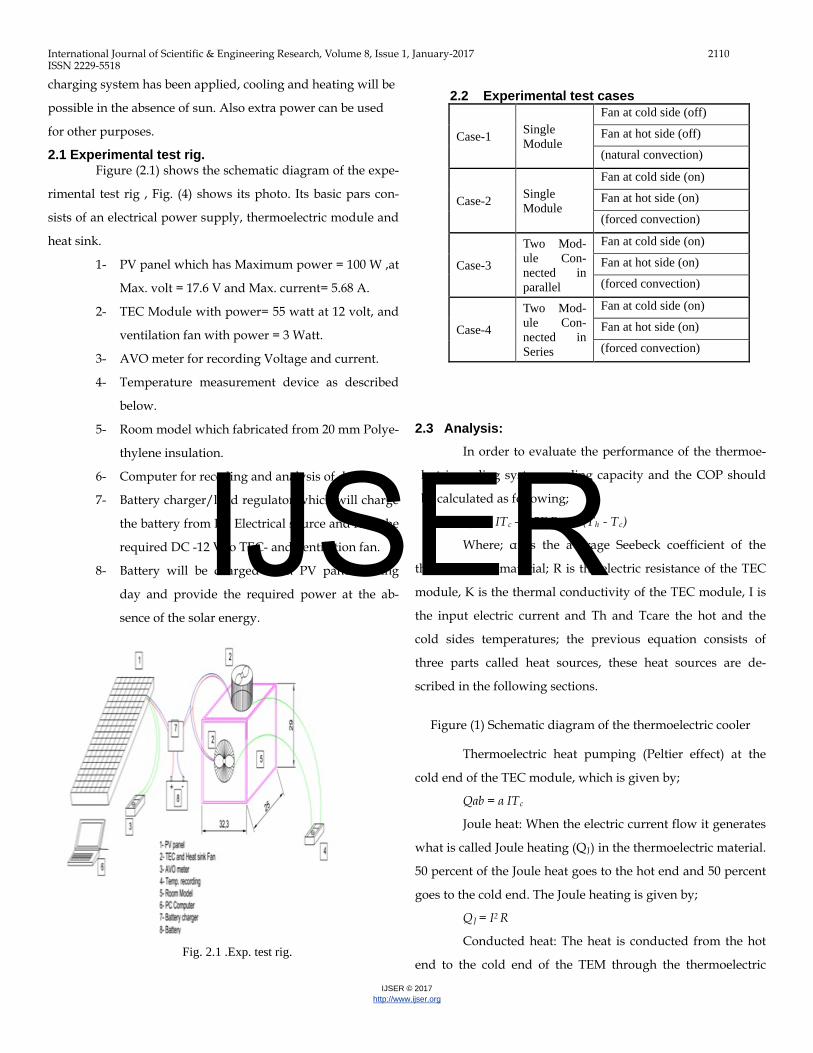
for other purposes. 2.1 Experimental test rig.
Figure (2.1) shows the schematic diagram of the expe-
rimental test rig , Fig. (4) shows its photo. Its basic pars con-
sists of an electrical power supply, thermoelectric module and
heat sink.
1- PV panel which has Maximum power = 100 W ,at
Max. volt = 17.6 V and Max. current= 5.68 A.
2- TEC Module with power= 55 watt at 12 volt, and
ventilation fan with power = 3 Watt.
3- AVO meter for recording Voltage and current.
4- Temperature measurement device as described
below.
5- Room model which fabricated from 20 mm Polye-
thylene insulation.
6- Computer for receding and analysis of data.
7- Battery charger/load regulator which will charge
the battery from PV Electrical source and feed the
required DC -12 V to TEC- and ventilation fan.
8- Battery will be charged from PV panel during
day and provide the required power at the ab-
sence of the solar energy.
RESULTS AND DISCUSSIONS
2.3 Analysis:
In order to evaluate the performance of the thermoe-
lectric cooling system, cooling capacity and the COP should
be calculated as following;
Qc = α ITc – 0.5I2 R – K (Th - Tc)
Where; α: is the average Seebeck coefficient of the
thermoelectric material; R is the electric resistance of the TEC
module, K is the thermal conductivity of the TEC module, I is
the input electric current and Th and Tcare the hot and the
cold sides temperatures; the previous equation consists of
three parts called heat sources, these heat sources are de-
scribed in the following sections.
Figure (1) Schematic diagram of the thermoelectric cooler
Thermoelectric heat pumping (Peltier effect) at the
cold end of the TEC module, which is given by;
Qab = α ITc
Joule heat: When the electric current flow it generates
what is called Joule heating (QJ) in the thermoelectric material.
50 percent of the Joule heat goes to the hot end and 50 percent
goes to the cold end. The Joule heating is given by;
QJ = I2 R
Conducted heat: The heat is conducted from the hot
end to the cold end of the TEM through the thermoelectric Fig. 2.1 .Exp. test rig.
2.2 Experimental test cases
Case-1 Single Module
Fan at cold side (off)
Fan at hot side (off)
(natural convection)
Case-2 Single Module
Fan at cold side (on)
Fan at hot side (on)
(forced convection)
Case-3
Two Mod-ule Con-nected in parallel
Fan at cold side (on)
Fan at hot side (on)
(forced convection)
Case-4
Two Mod-ule Con-nected in Series
Fan at cold side (on)
Fan at hot side (on)
(forced convection)
IJSER
International Journal of Scientific & Engineering Research, Volume 8, Issue 1, January-2017 2111 ISSN 2229-5518
IJSER © 2017 http://www.ijser.org
material during the operation process. This conduction heat
rate is given by;
Qcd = K (Th-Tc)
The above equation shows that Qcd increases across the TEM
with the temperature difference.
The electrical energy consumption of the TEM is giv-
en by;
P = α I ∆T + I2 R
The COP of the TEM for cooling is given by;
COP = Qc / P = [α I Tc – 0.5 I2 R – K(Th-Tc)]/[α I ∆T- I2R]
From the previous equation it seems that the COP is a function
of the material dimension property of thermoelectric material,
hot and cold sides temperatures Th ; Tc and input current.
α; Seebeck coefficient; α = VMAX /Th
Rm; Resistance of module; Rm = [(Th-∆Tmax)xV]/ITh
k – Thermal conductivity;K= [(Th-∆Tmax)xIV]/[ ∆Tmax x Th]
Where the values of the variables are taken from handbook
and various data
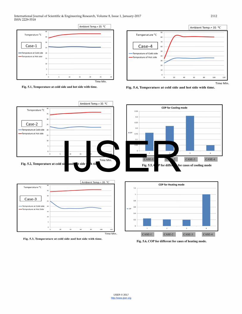
3 RESULTS AND DISCUSSION In this section the experimental results are in case-1 curve (Fig.
5-1) represented the performance of TEC module with natural
convection heat transfer for both cold and hot sides for one
TEC module, it is observed that the temperature of cold and
hot side has ranges higher than 25 oC and 38 oC respectively,
and the Electrical current reached 1.3 A.
Case-2 curve (Fig. 5-2) represented the performance of TEC
module with forced convection heat transfer for both cold and
hot sides for one TEC module, it is observed that the tempera-
ture of cold and hot side has ranges lower than 23 oC and 36.5
oC respectively, and the Electrical current reached 0.4 A.
which indicates that forced convection is more effective than
natural convection for cooling mode, and vice versa in heating
mode, natural convection is more effective than forced convec-
tion for heating mode.
Case-3 curve (Fig. 5-3) represented the performance of TEC
modules with parallel connection for two TEC modules, it is
observed that the temperature of cold side has a ranges lower
than 19 oC and the temperature of hot side has a ranges higher
than 36oC, and the Electrical current reached 2.5 A. which in-
dicates that the parallel connection decrease the temperature
of cold side which means more efficiency for cooling mode.
Case-4 curve (Fig. 5-4) represented the performance of
TEC modules with Series connection for two TEC mod-
ules, it is observed that the temperature of cold side has a
ranges higher than 35 oC and the temperature of hot side
has a ranges higher than 80 oC, and the Electrical current
reached 4.9 A. which indicates that the Series connection
increase the temperature of hot side which means more ef-
ficiency for heating mode.
COP curve (Fig. 5-5) represented the performance of
TEC modules with Cooling mode, it is observed that
COP of
- cooling is the highest at case three i.e. connecting several
TEC modules in parallel connection and forced convection
will be the optimum for cooling mode.
- COP curve (Fig. 5-6) represented the performance of TEC
modules with heating mode, it is observed that COP of heat-
ing is the highest at case FOUR i.e. connecting several TEC
modules in series connection and forced convection will be the
optimum for heating mode.
Natural convection leads to high range temperature
in both cold and hot sides, but using of forced convection will
leads to lower temperature ranges.
Connecting of TE modules in parallel suitable for cooling pur-
pose, and connecting TE modules in series suitable for heating
purpose.
IJSER
International Journal of Scientific & Engineering Research, Volume 8, Issue 1, January-2017 2112 ISSN 2229-5518
IJSER © 2017 http://www.ijser.org
IJSER
International Journal of Scientific & Engineering Research, Volume 8, Issue 1, January-2017 2113 ISSN 2229-5518
IJSER © 2017 http://www.ijser.org
4 CONCLUSIONS 1- HAP calculations help in selecting of TEC/PV panel selec-
tion indicating The steps for Designing and selection of
TEC/PV air conditioning System.
2- COP in Forced convection air system is better than natural
convection air system.
3- COP when connecting TEC Modules in Parallel is better
than in series connection.
REFERENCES [1] http://www.akasa.com [2] [Gillott Mark, Liben Jiang and SaffaRiffat, (2010).An investigation of thennoelectric
cooting devices for small-scale space conditioning applications ill buildings, Interna-tional Journal ofEnergy Research, 34: 776-786.
[3] Bansal P. K.And Martin A, (2000).Comparative study of vapour compression, ther-moelectric and absorption refrigerators, International Journal of Energy Research, 24: 93-107.
[4] Hara T, Azum H. Cooling performance of solar cell driven, thermoelectric cooling prototype headgear. Applied Thermal Engineering 1998; 18:1159–69.
[5] Liu, D., Zhao, F. Y, Yang, H. X., & Tang, G. F. (2015). Thermoelectric mini cooler coupled with micro thermosyphon for CPU cooling system. Energy, 83, 29-36.
[6] Abdul-Wahab, S. A, Elkame~ A, Al-Darnkhi, A M., Is' haq, A, Al-Rubai'ey, H. S., Al-Battashi, A K., &Chutani, M. U. (2009). Design and experimental investigation ofportable solar thermoelectric refrigerator. Renewable Energy, 34(1), 30-34.
[7] Abdullah M. 0., J. L. Ngui, K. Abd.Hamid, S. L. Leo, and S. H. Tie, (2009).Cooling Perfonnance of a Combined Solar Thermoelectric Adsorption Cooling System: An Ex-perimental Study, Energy Fuels, 23: 5677-5683.
[8] Gurevich, Y. G., Logvinov, G. N., Titov, O. Y., &Giraldo, J. (2002).New physical principles of contact thermoelectric cooling. Surface Review and Letters, 9(05n06), 1703-1708.
[9] [Dai Y. J., Wang R. Z. and L. Ni, (2003). Experimental investigation and analysis on a thermoelectric refrigerator driven by solar cells, Solar energy material and solar cells 77:377-391.
[10] Dai, Y. 1., Wang, R. Z., & Ni, L. (2003).Experimental investigation and analysis on a thermoelectric refrigerator driven by solar cells. Solar energy materials and solar cells, 77(4),377-391.
[11] Putra N. (2009).Design, manufacturing and testing of a portable vaccine carrier box employing thermoelectric module and heat pipe, Journal of Medical Engineering & Technology, 33 (3): 232-237.
[12] Chang, Y. W., Cheng, C. H., Wu, W. F., & Chen, S. L. (2007). An experimental investigation of thermoelectric air-cooling module. In Proceedings of World Academy of Science, Engineering and Technology (Vol. 33, pp. 128-133).
[13] Adeyanju A.A., E. Ekwue and W. Compton, (2010). Experimental and Theoretical Analysis of a Beverage Chiller, Research Journal of Applied Science, 5 (3): 195-203.
[14] Vian, 1. G., &Astrain, D. (2009).Development of a thermoelectric refrigerator with two-phase thermosyphons and capillary lift. Applied Thermal Engineering,29(10), 1935-1940.
[15] Brovman, Y. M., Small, 1. P., Hu, Y., Fang, Y., Lieber, C. M., & Kim, P. (2013).Electric field effect thermoelectric transport in individual Silicon and Germanium/Silicon nanowire.arXiv preprint arXiv: 1307.0249.
[16] David et al. David, B., Rarnousse, 1., &Luo, L. (2012).Optimization of thermoelectric heat pumps by operating condition management and heat exchanger design. Energy Conversion and Management, 60, 125-133.
[17] Rao and Patel Rao, R. V., & Patel, V. (2013).Multi-objective optimization of two stage
thermoelectric cooler using a modified teaching-learning-based optimization algorithm. Engineering Applications of Artificial Intelligence, 26(1),430-445.
[18] Owoyele et aI. Owoyele, 0., Ferguson, S., & O'Connor, B. T. (2015).Performance analysis of a thermoelectric cooler with a corrugated architecture. Applied Energy, 147, 184-191.
IJSER