thermoelectric generator development efforts at the maine
TRANSCRIPT
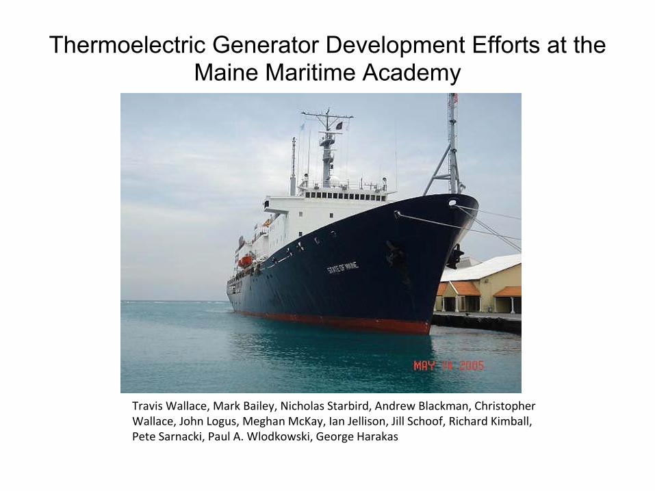
Thermoelectric Generator Development Efforts at the Maine Maritime Academy
Travis Wallace, Mark Bailey, Nicholas Starbird, Andrew Blackman,
Christopher
Wallace, John Logus, Meghan McKay, Ian Jellison, Jill Schoof, Richard Kimball,
Pete Sarnacki, Paul A. Wlodkowski, George Harakas
Setting a Course for Thermoelectric Applications

Why Look at Marine Applications For TEGs?
• Marine Applications not Sensitive to Weight and Size Constraints
• Efficiency Improvements are of Critical Importance to Industry
• Shipping Industry can be an Early Adopter of this Enabling Technology
• Ships have Onboard Infrastructure for Electric Power Generation.
• Provides an auxiliary generator using waste heat only
• Opportunity of reduce CO2
emissions (Green Technology)
• Low emission vessels are needed NOW: Port of Los Angeles Hybrid Tug Boat

General Concept
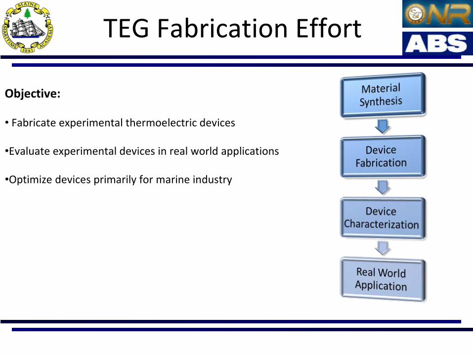
TEG Fabrication Effort
Objective:
• Fabricate experimental thermoelectric devices
•Evaluate experimental devices in real world applications
•Optimize devices primarily for marine industry
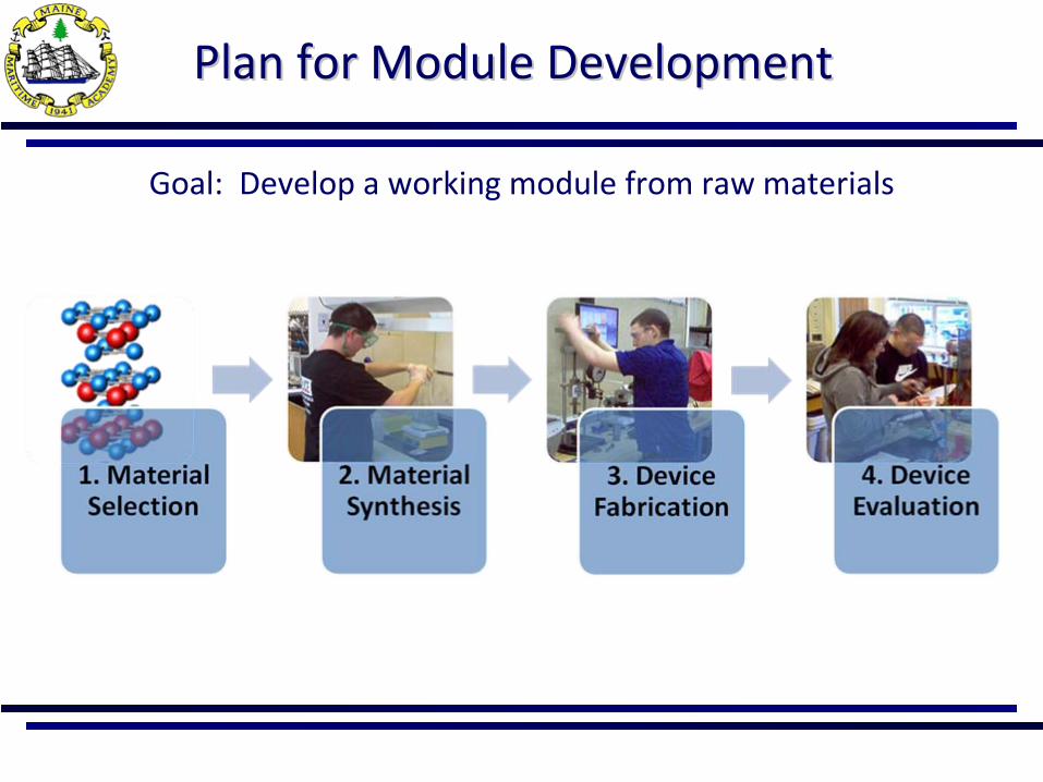
Plan for Module Development Plan for Module Development
Goal: Develop a working module from raw materials
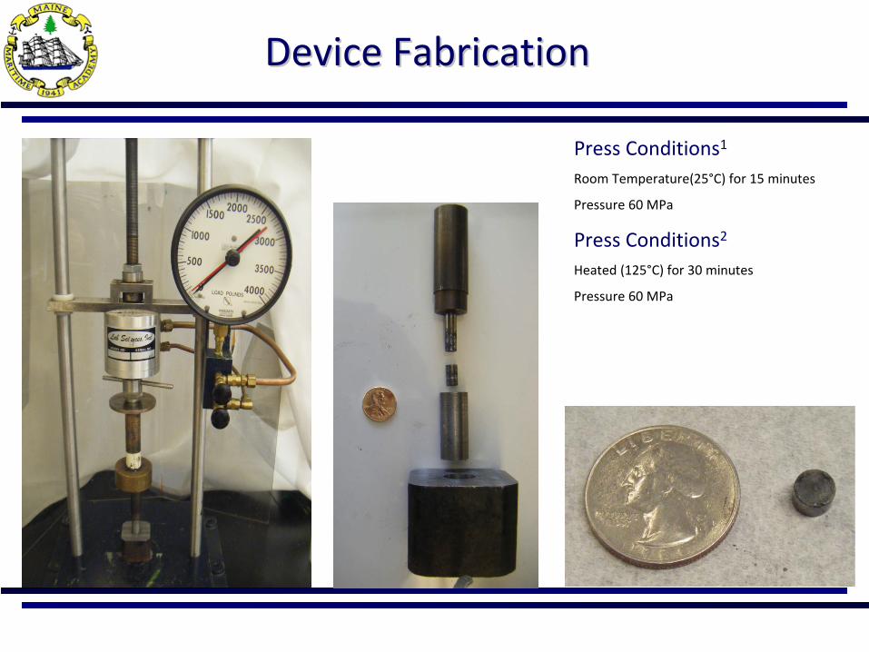
Device FabricationDevice Fabrication
Press Conditions1
Room Temperature(25°C) for 15 minutes
Pressure 60 MPa
Press Conditions2
Heated (125°C) for 30 minutes
Pressure 60 MPa
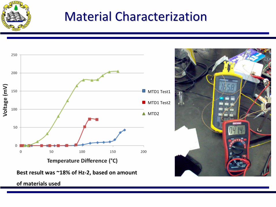
Material CharacterizationMaterial Characterization
MTD1 Test1
MTD1 Test2
MTD2
Best result was ~18% of Hz‐2, based on amount
of materials used

Platform for Gas Turbine Testing
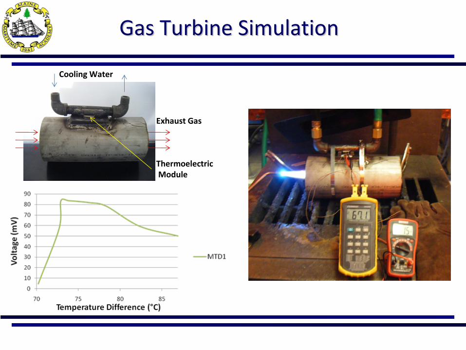
Gas Turbine SimulationGas Turbine Simulation
Cooling Water
Exhaust Gas
ThermoelectricModule
Commercial Modules HiCommercial Modules Hi‐‐ZZ
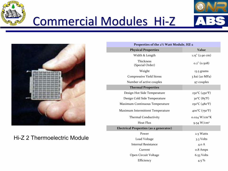
Properties of the 2½
Watt Module, HZ‐2
Physical Properties Value
Width & Length 1.15" (2.90 cm)
Thickness
(Special Order) 0.2" (0.508)
Weight 13.5 grams
Compressive Yield Stress 3 ksi (20 MPa)
Number of active couples 97 couples
Thermal Properties
Design Hot Side Temperature 230°C (450°F)
Design Cold Side Temperature 30°C (85°F)
Maximum Continuous Temperature 250°C (480°F)
Maximum Intermittent Temperature 400°C (750°F)
Thermal Conductivity 0.024 W/cm*K
Heat Flux 9.54 W/cm2
Electrical Properties (as a generator)
Power 2.5 Watts
Load Voltage 3.3 Volts
Internal Resistance 4.0 A
Current 0.8 Amps
Open Circuit Voltage 6.53 Volts
Efficiency 4.5 %
Hi-Z 2 Thermoelectric Module

Experimental SetExperimental Set‐‐up up
Hi Z modules
Hz 2
Hz 14
Hz 20 (Right)
National Instruments LabView 8.2
LabJack U12
Audon TCK‐4 Amplifier
2 Type K Thermocouples
Corning Hot Plate
Ice Bath

HZ 2 Module Testing
250ºC 325ºC300ºC 350ºC 400ºC
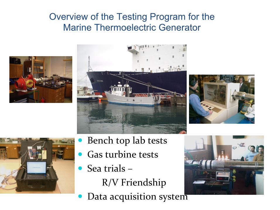
Overview of the Testing Program for the Marine Thermoelectric Generator
Bench top lab tests
Gas turbine tests
Sea trials –
R/V Friendship
Data acquisition system

Hi‐Z’s 180W thermoelectric unit
Acquired from Hi‐Z Technology, Inc.
(Hi‐Z), the thermoelectric unit
consists of 18 HZ‐14 modules
connected in 2 parallel circuits.
Maximum temperature values were
supplied as 250
oC for the exhaust
side.

MATLAB Mathematical Model
Bulk Parameter Finite Element Solver
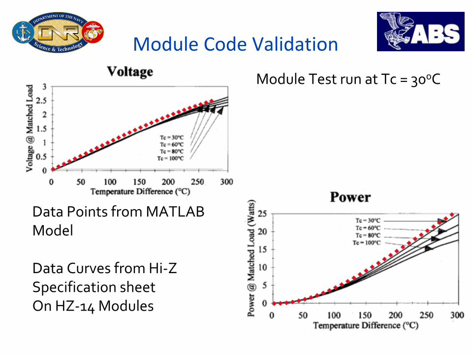
Module Code Validation
Module Test run at Tc = 300C
Data Points from MATLAB
Model
Data Curves from Hi‐Z
Specification sheetOn HZ‐14 Modules
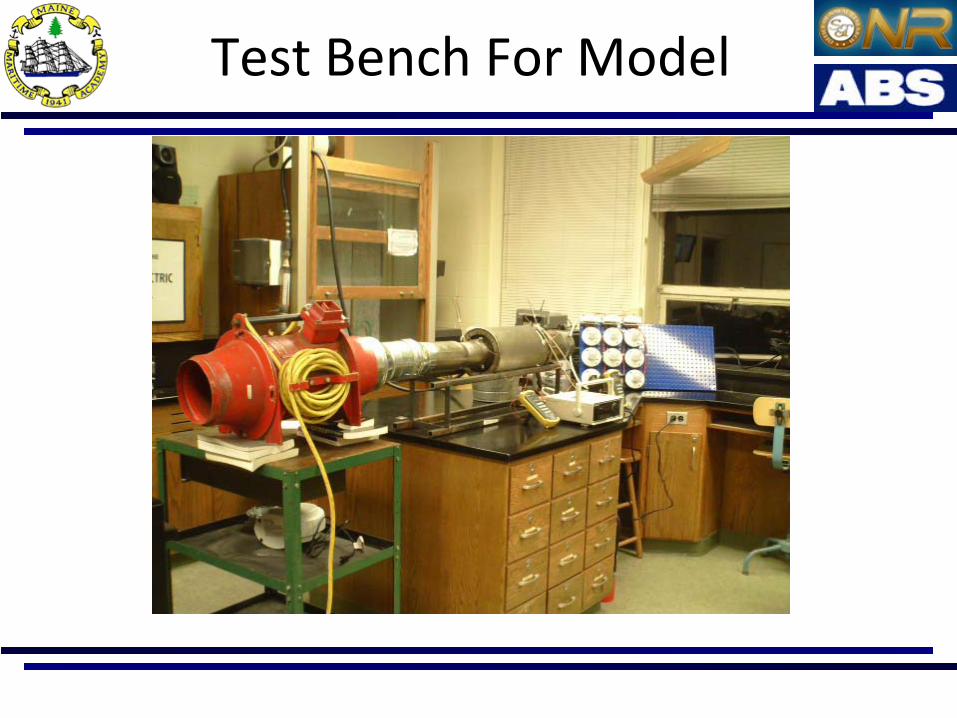
Test Bench For Model
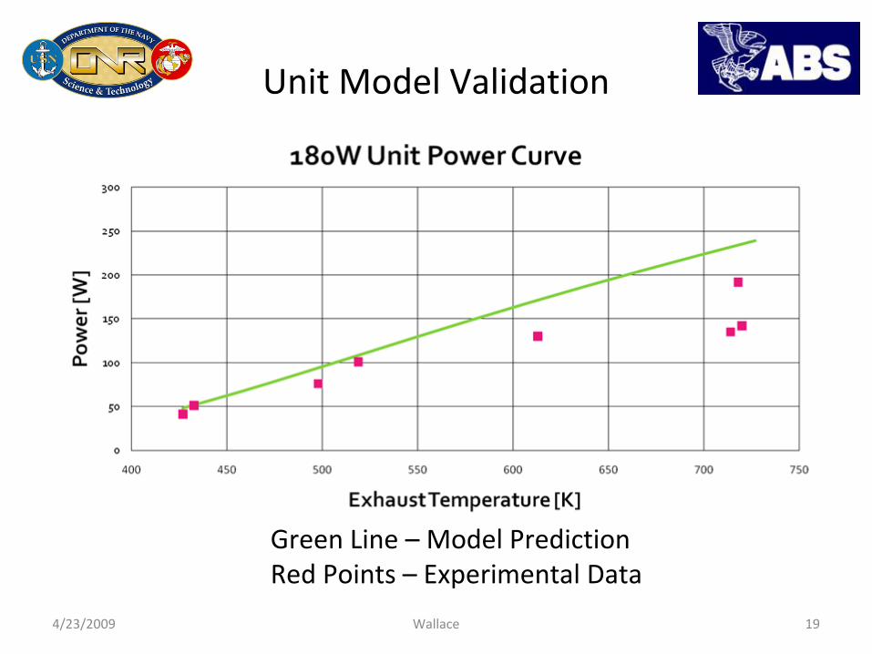
Unit Model Validation
4/23/2009 Wallace 19
Green Line – Model PredictionRed Points –
Experimental Data
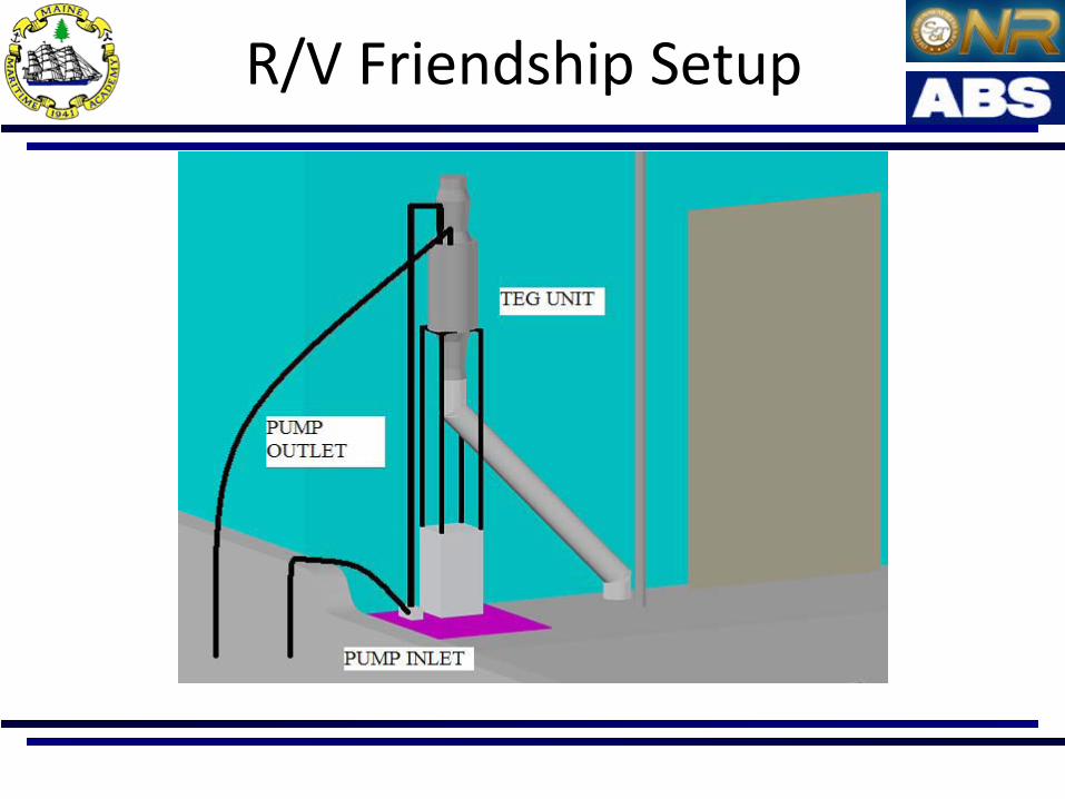
R/V Friendship Setup
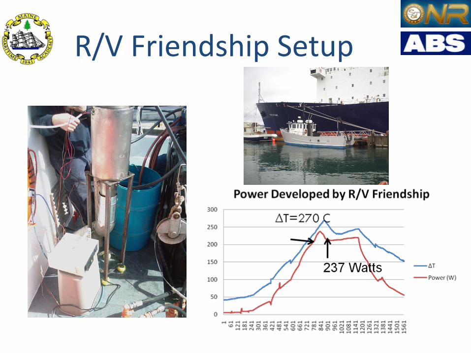
R/V Friendship Setup
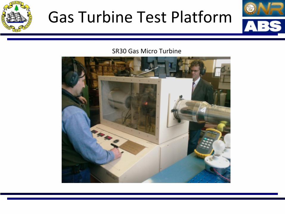
Gas Turbine Test Platform
SR30 Gas Micro Turbine
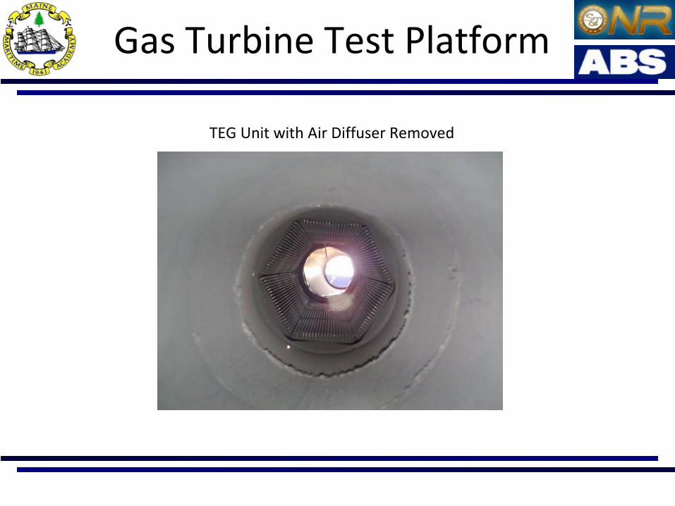
Gas Turbine Test Platform
TEG Unit with Air Diffuser Removed
Gas Turbine Test Platform
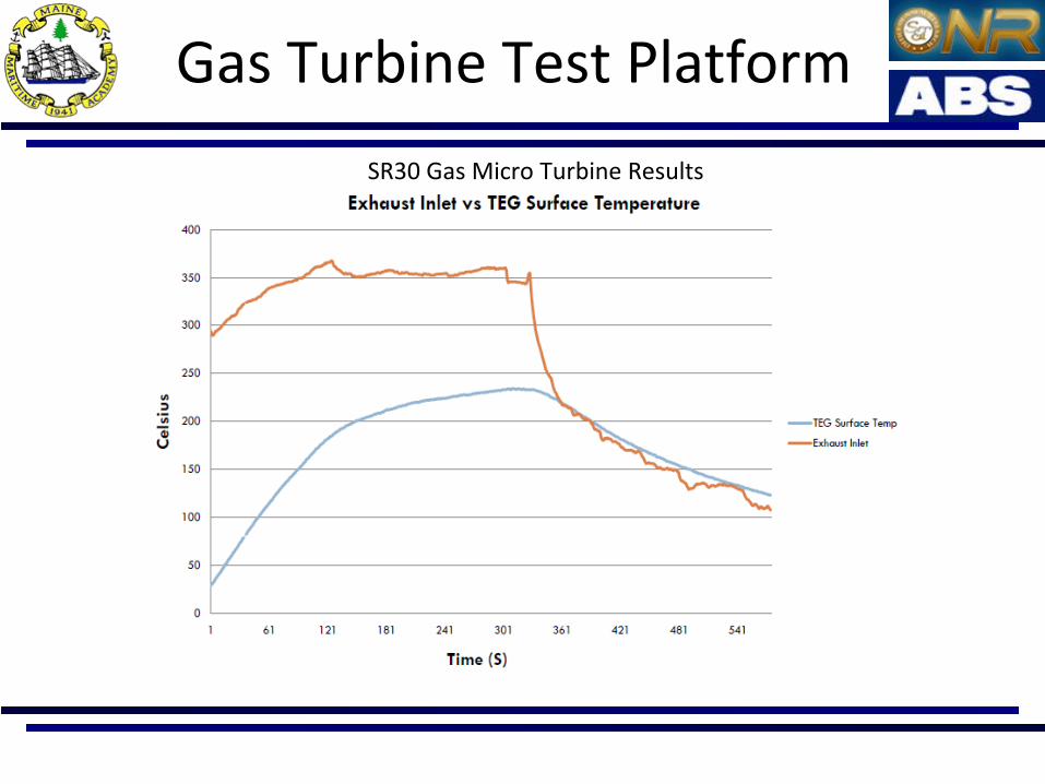
SR30 Gas Micro Turbine Results

192 Watts
SR30 Results

Economics vs. Environment
Assumptions:
80% Duty
LHV=42000kJ/kg
η=0.45
Fuel Cost=$1/gal
Increase TEG
Decrease CO2
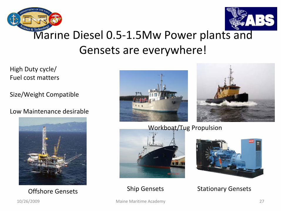
Marine Diesel 0.5‐1.5Mw Power plants and Gensets are everywhere!
10/26/2009 Maine Maritime Academy 27
QuickTime™ and aTIFF (Uncompressed) decompressor
are needed to see this picture.
Ship Gensets
Workboat/Tug Propulsion
Offshore Gensets Stationary Gensets
High Duty cycle/Fuel cost matters
Size/Weight Compatible
Low Maintenance desirable
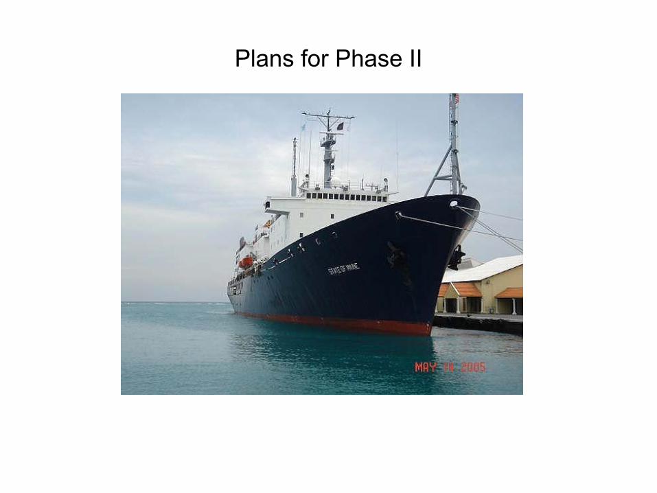
Plans for Phase II
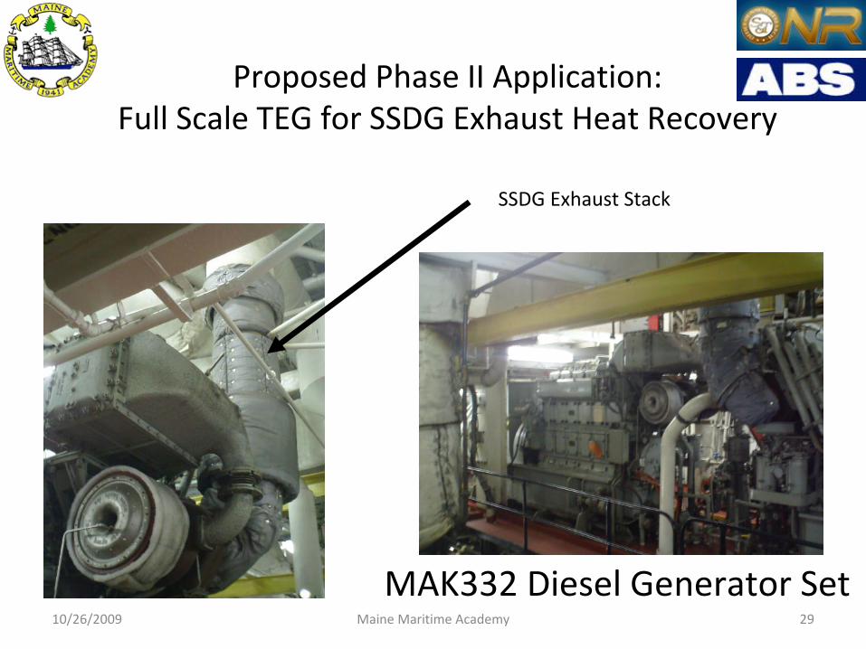
Proposed Phase II Application: Full Scale TEG for SSDG Exhaust Heat Recovery
MAK332 Diesel Generator Set 10/26/2009 Maine Maritime Academy 29
SSDG Exhaust Stack
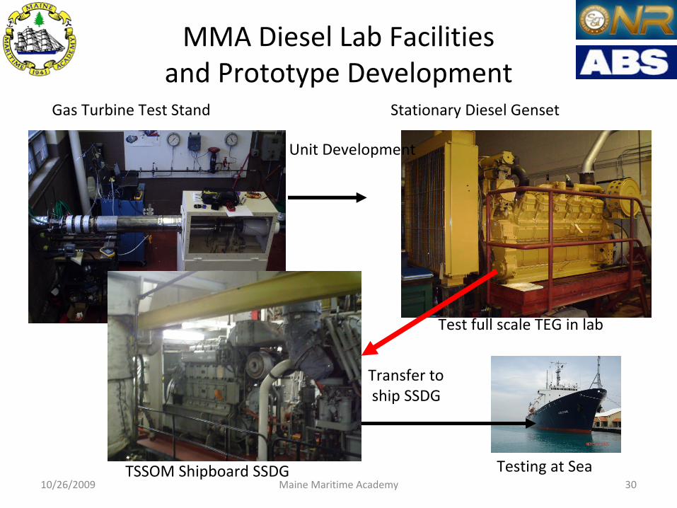
MMA Diesel Lab Facilities and Prototype Development
10/26/2009 Maine Maritime Academy 30
Gas Turbine Test Stand Stationary Diesel Genset
TSSOM Shipboard SSDG Testing at Sea
Unit Development
Test full scale TEG in lab
Transfer toship SSDG

Conclusions and Future Plans:
Early results show that Thermoelectric Power Generation ispromising for applications in the Maritime Industry
Numerous challenges are involved in scale up, power regulation 440 V, testing advanced materials (beyond Bi2
Te3
)....
-Summer 2009 Data Collection on TS State of Maine- Fall 2009 Development and configuration of test labs and
computer model- TEG Design and development Fall2009/Spring 2009- Construction of TEG prototype Spring/Summer 2010- Lab Testing Fall 2010- Install on TSSOM Spring 2010- Test on Cruise 2010- Acquire additional vessels for TEG installation- Position MMA to be a leader in the field of TEGs in the Marine industry

Acknowledgments Acknowledgments
CorporateAmerican Bureau of ShippingDepartment of EnergyNaval Surface Warfare Center, CarderockMaine Maritime Academy
FacultyProfessor Richard KimballProfessor Paul WlodkowskiProfessor George HarakasProfessor Jill SchoofProfessor Mark LibbyProfessor Larry WadeProfessor Barbra Fleck
StudentsAndrew BlackmanChris BellowsTravis WallaceMark BaileyNick StarbirdChristopher WallaceJohn LogusMeghan McKayIan Jellison
Special Thanks to: John Fair Banks DOE and Norbert Eisner Hi‐Z