thermoelectric generator development for …...thermoelectric generator development for automotive...
TRANSCRIPT
Thermoelectric Generator Development for Automotive
Waste Heat Recovery Gregory P. Meisner
General Motors Global Research & Development
16th Directions in Engine Efficiency andEmissions Research (DEER) Conference
Detroit, MichiganSeptember 29, 2010
2
• Acknowledgements• Introduction• Thermoelectric Materials Research• Thermoelectric Generator Development• Summary
Outline
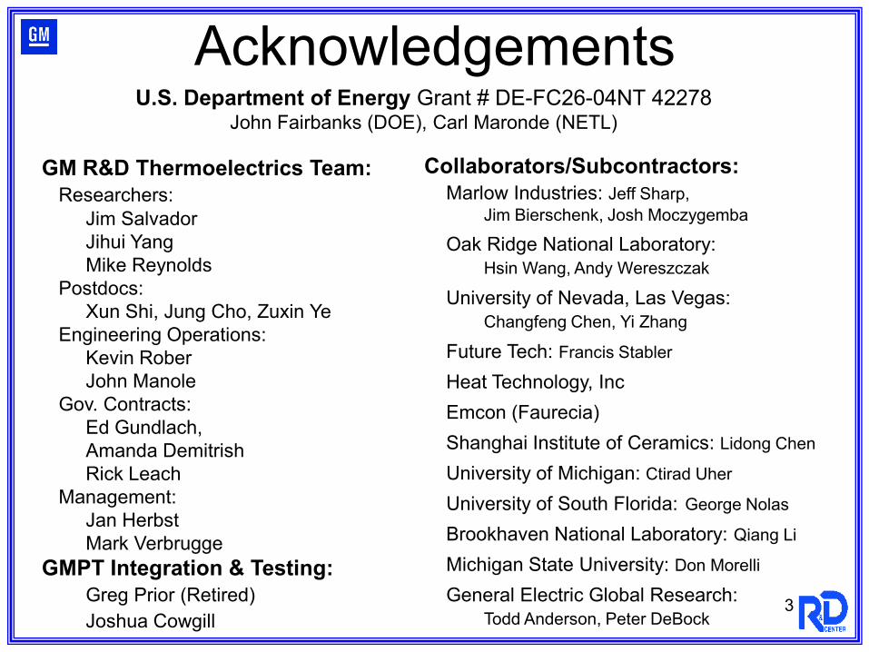
GM R&D Thermoelectrics Team:Researchers:
Jim SalvadorJihui YangMike Reynolds
Postdocs:Xun Shi, Jung Cho, Zuxin Ye
Engineering Operations:Kevin RoberJohn Manole
Gov. Contracts:Ed Gundlach, Amanda DemitrishRick Leach
Management:Jan HerbstMark Verbrugge
GMPT Integration & Testing:Greg Prior (Retired)Joshua Cowgill
Collaborators/Subcontractors:Marlow Industries: Jeff Sharp,
Jim Bierschenk, Josh Moczygemba
Oak Ridge National Laboratory:Hsin Wang, Andy Wereszczak
University of Nevada, Las Vegas:Changfeng Chen, Yi Zhang
Future Tech: Francis Stabler
Heat Technology, IncEmcon (Faurecia)Shanghai Institute of Ceramics: Lidong Chen
University of Michigan: Ctirad Uher
University of South Florida: George Nolas
Brookhaven National Laboratory: Qiang Li
Michigan State University: Don Morelli
General Electric Global Research:Todd Anderson, Peter DeBock
Acknowledgements
3
U.S. Department of Energy Grant # DE-FC26-04NT 42278 John Fairbanks (DOE), Carl Maronde (NETL)
Com
bust
ion
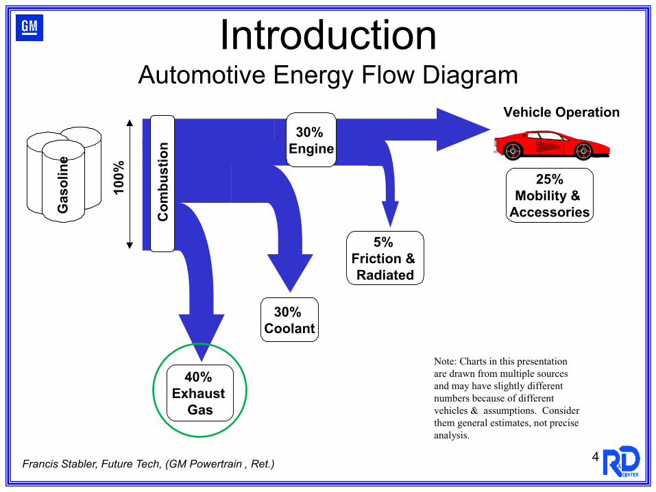
30% Engine
Vehicle Operation10
0%
40% Exhaust
Gas
30% Coolant
5% Friction & Radiated
25%Mobility &
Accessories
Gas
olin
eG
asol
ine
Gas
olin
eG
asol
ine
Gas
olin
eG
asol
ine
Note: Charts in this presentation are drawn from multiple sourcesand may have slightly different numbers because of different vehicles & assumptions. Considerthem general estimates, not preciseanalysis.
Francis Stabler, Future Tech, (GM Powertrain , Ret.)
IntroductionAutomotive Energy Flow Diagram
4
5
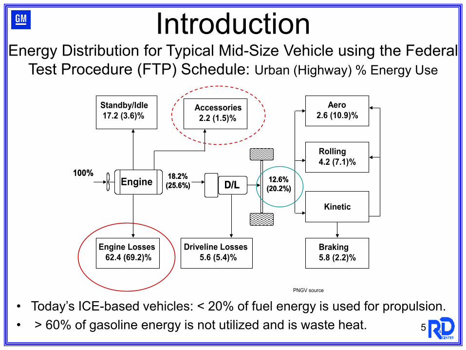
• Today’s ICE-based vehicles: < 20% of fuel energy is used for propulsion.• > 60% of gasoline energy is not utilized and is waste heat.
Standby/Idle 17.2 (3.6)%
Engine Losses62.4 (69.2)%
Accessories2.2 (1.5)%
Driveline Losses5.6 (5.4)%
Aero2.6 (10.9)%
Rolling4.2 (7.1)%
Kinetic
Braking5.8 (2.2)%
Engine100% 18.2%
(25.6%) D/L 12.6%(20.2%)
Standby/Idle 17.2 (3.6)%
Engine Losses62.4 (69.2)%
Engine Losses62.4 (69.2)%
Accessories2.2 (1.5)%
Accessories2.2 (1.5)%
Driveline Losses5.6 (5.4)%
Driveline Losses5.6 (5.4)%
Aero2.6 (10.9)%
Aero2.6 (10.9)%
Rolling4.2 (7.1)%Rolling4.2 (7.1)%
KineticKinetic
Braking5.8 (2.2)%Braking5.8 (2.2)%
EngineEngine100% 18.2%
(25.6%) D/LD/L 12.6%(20.2%)
PNGV source
IntroductionEnergy Distribution for Typical Mid-Size Vehicle using the Federal
Test Procedure (FTP) Schedule: Urban (Highway) % Energy Use
6
Approach:Thermoelectric Materials Research: discover, investigate, optimize advanced TEs Incorporate new advanced TE materials into operational devices & vehicle systemsIntegrate/Load Match advanced TE systems with vehicle electrical networksVerify device & system performance under operating conditions
US Department of Energy:Funding Opportunity Announcement No. DE-PS26-04NT42113, “Energy Efficiency Renewable Energy (EERE) - Waste Heat Recovery and Utilization Research and Development for Passenger Vehicle and Light/Heavy Duty Truck Applications”
Introduction
Achieve 10 % improvement in fuel economy (FE) by 2015 without increasing emissions
Demonstrate FE improvement for the Federal Test Procedure driving cycle (~3%)Demonstrate that actual FE improvement for real world driving conditions is closer to DOE goal
Demonstrate commercial viability Assemble, install, and test prototype TEG on a production vehicleCollect performance data, show viabilityIdentify specific design, engineering, and manufacturability improvements for path to production
7
Introduction
H
CH
CH
TT
ZT
ZTT
TT
++
−+−=
1
11ε
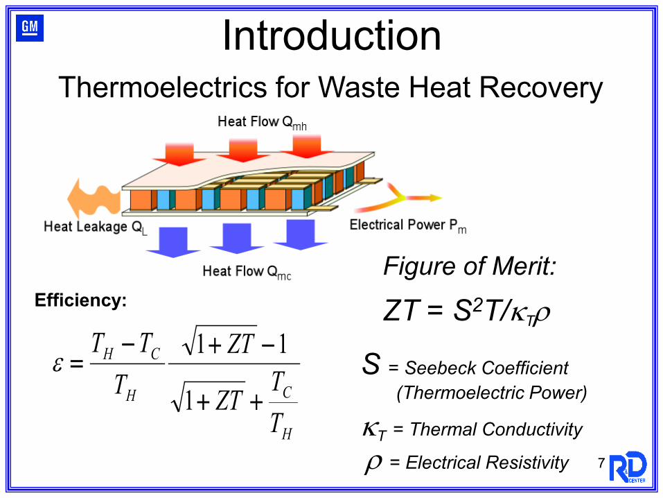
Efficiency:Figure of Merit:
ZT = S2T/κTρ
S = Seebeck Coefficient (Thermoelectric Power)
κT = Thermal Conductivity
ρ = Electrical Resistivity
Thermoelectrics for Waste Heat Recovery
8
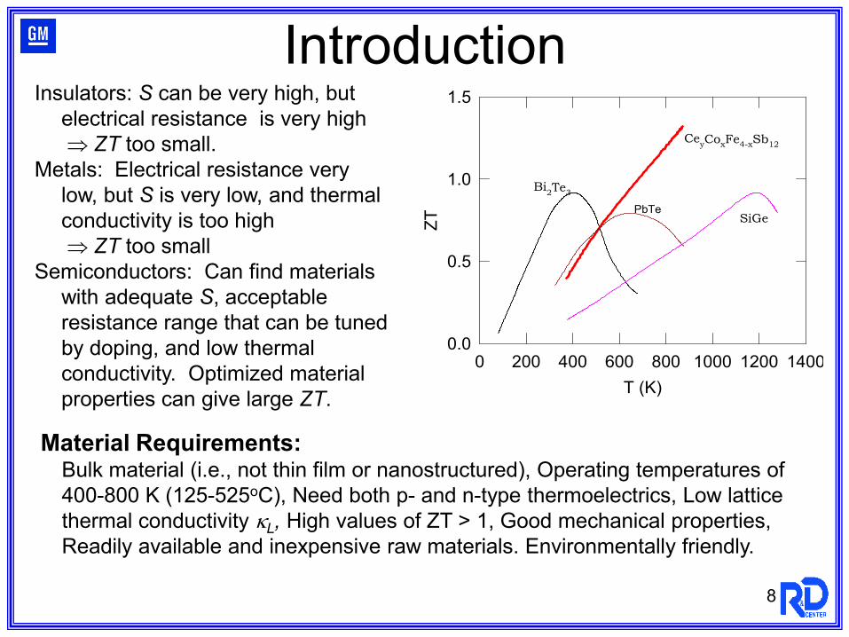
Insulators: S can be very high, but electrical resistance is very high⇒ ZT too small.
Metals: Electrical resistance verylow, but S is very low, and thermal conductivity is too high⇒ ZT too small
Semiconductors: Can find materials with adequate S, acceptable resistance range that can be tuned by doping, and low thermal conductivity. Optimized material properties can give large ZT.
Introduction
T (K)0 200 400 600 800 1000 1200 1400
ZT
0.0
0.5
1.0
1.5
Bi2Te3
SiGe
CeyCoxFe4-xSb12
PbTe
Material Requirements:Bulk material (i.e., not thin film or nanostructured), Operating temperatures of 400-800 K (125-525oC), Need both p- and n-type thermoelectrics, Low lattice thermal conductivity κL, High values of ZT > 1, Good mechanical properties, Readily available and inexpensive raw materials. Environmentally friendly.
9
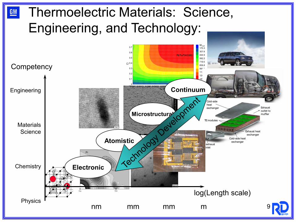
Thermoelectric Materials: Science, Engineering, and Technology:
nm mm mm m
log(Length scale)
Engineering
MaterialsScience
Chemistry
Physics
Competency
Electronic
Microstructural
0.001 0.0015 0.002 0.0025 0.003 0.0035 0.004 0.0045 0.0050
0.1
0.2
0.3
0.4
0.5
0.6
0.7
140612691131994.1856.8719.5582.2444.9307.6170.3
Lp [m]
Wout
PbTe/TAGS85
Continuum
Atomistic
Cold-side heat exchanger
TE modules
Exhaust outlet to muffler
Cold-side heat exchanger
Hot exhaust inlet
Exhaust heat exchanger
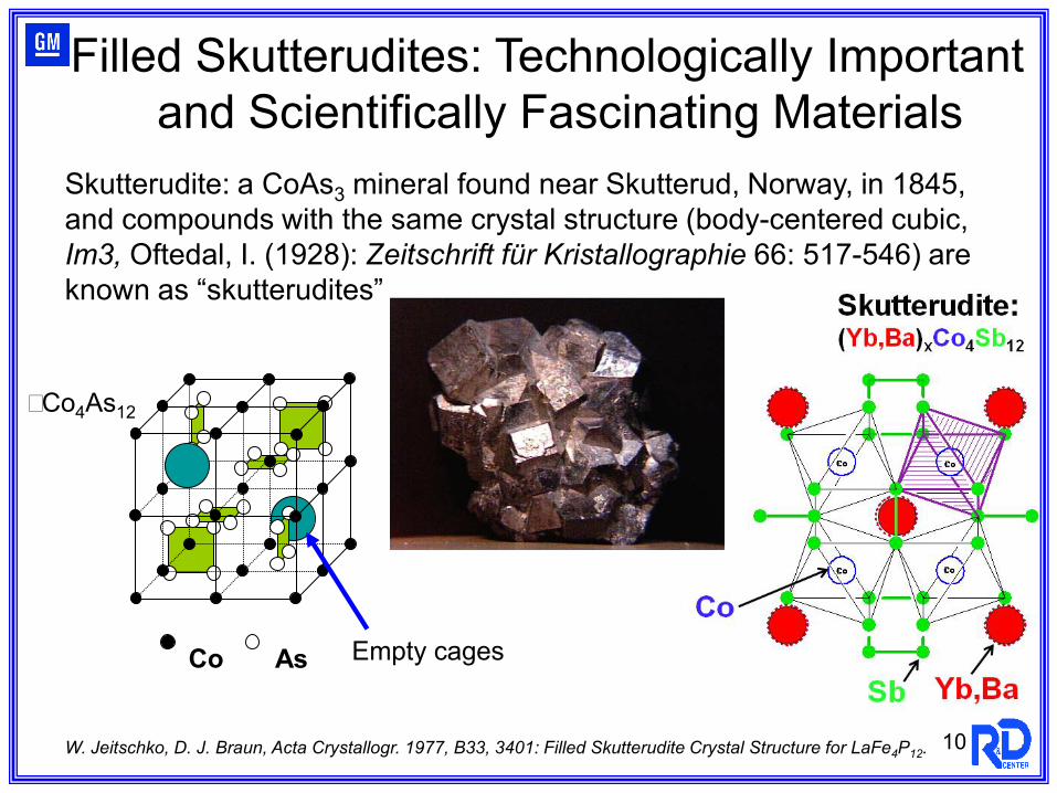
Skutterudite: a CoAs3 mineral found near Skutterud, Norway, in 1845, and compounds with the same crystal structure (body-centered cubic, Im3, Oftedal, I. (1928): Zeitschrift für Kristallographie 66: 517-546) are known as “skutterudites”
W. Jeitschko, D. J. Braun, Acta Crystallogr. 1977, B33, 3401: Filled Skutterudite Crystal Structure for LaFe4P12. 10
Filled Skutterudites: Technologically Important and Scientifically Fascinating Materials
Co As
�Co4As12
Empty cages
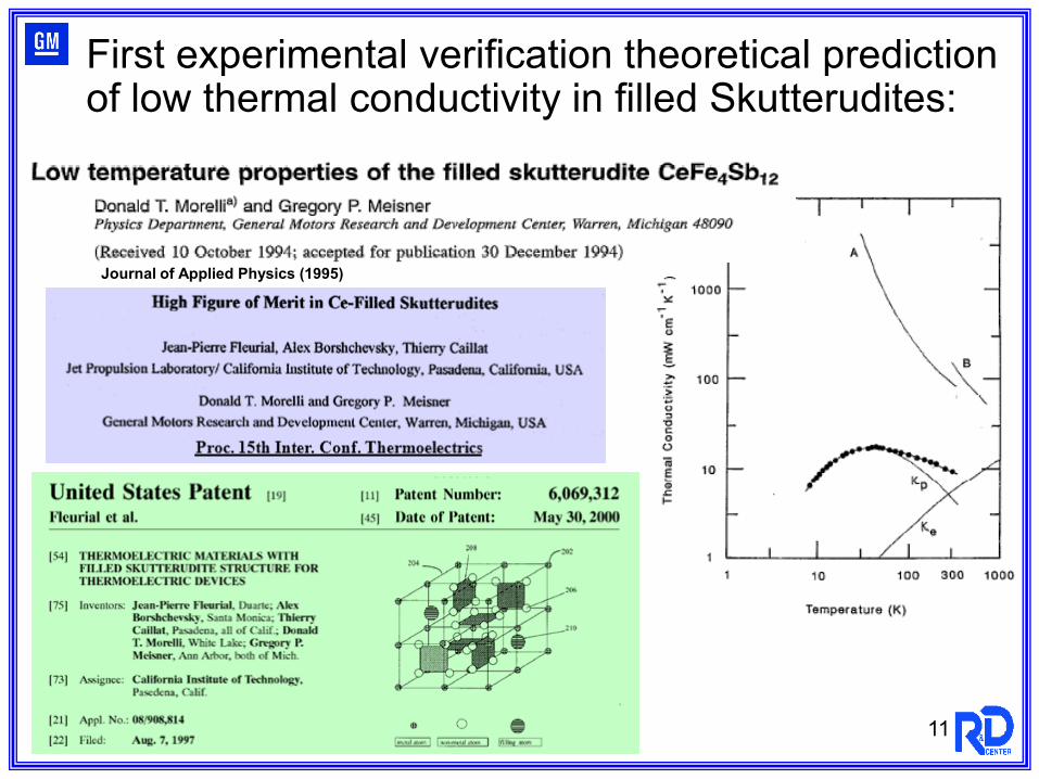
Journal of Applied Physics (1995)
11
First experimental verification theoretical prediction of low thermal conductivity in filled Skutterudites:
12
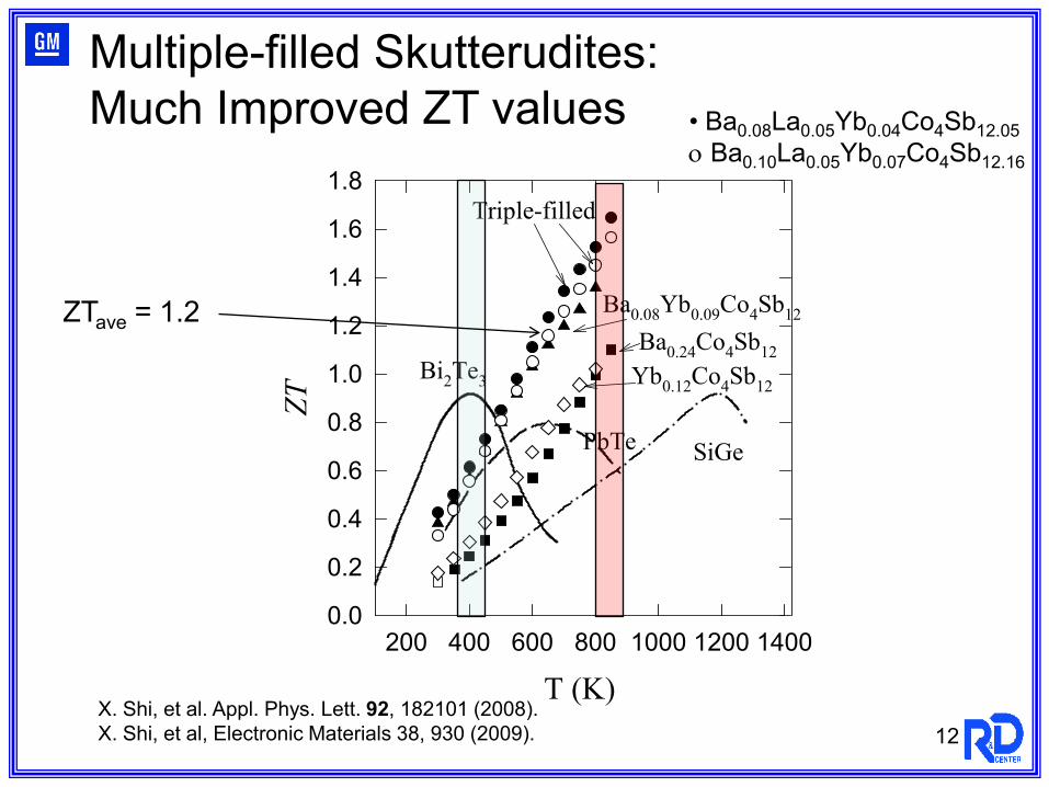
T (K)200 400 600 800 1000 1200 1400
ZT
0.0
0.2
0.4
0.6
0.8
1.0
1.2
1.4
1.6
1.8
Bi2Te3
PbTe SiGe
Ba0.24Co4Sb12
Ba0.08Yb0.09Co4Sb12
Triple-filled
Yb0.12Co4Sb12
ZTave = 1.2
• Ba0.08La0.05Yb0.04Co4Sb12.05ο Ba0.10La0.05Yb0.07Co4Sb12.16
Multiple-filled Skutterudites:Much Improved ZT values
X. Shi, et al. Appl. Phys. Lett. 92, 182101 (2008).X. Shi, et al, Electronic Materials 38, 930 (2009).
13
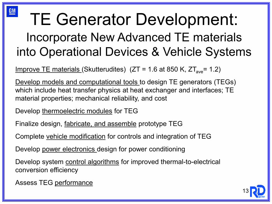
Incorporate New Advanced TE materials into Operational Devices & Vehicle SystemsImprove TE materials (Skutterudites) (ZT = 1.6 at 850 K, ZTave= 1.2)
Develop models and computational tools to design TE generators (TEGs) which include heat transfer physics at heat exchanger and interfaces; TE material properties; mechanical reliability, and cost
Develop thermoelectric modules for TEG
Finalize design, fabricate, and assemble prototype TEG
Complete vehicle modification for controls and integration of TEG
Develop power electronics design for power conditioning
Develop system control algorithms for improved thermal-to-electrical conversion efficiency
Assess TEG performance
TE Generator Development:
14
n p
metal
metalmetal
metal
conductor
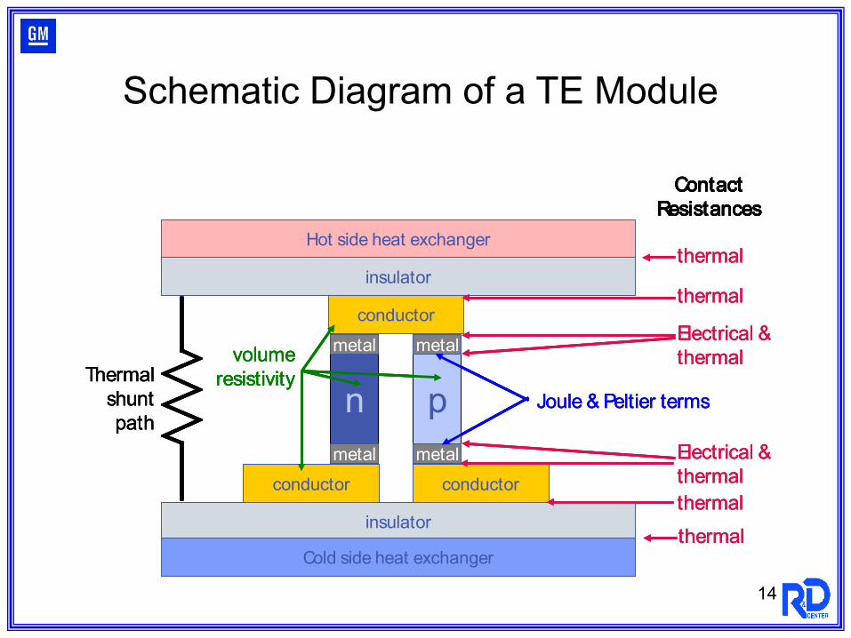
ContactResistances
conductor conductor
insulator
insulator
Hot side heat exchanger
Cold side heat exchanger
thermal
thermal
Electrical &thermal
thermal
thermal
volumeresistivity
Electrical &thermal
Thermal shunt path
Joule & Peltier terms
n p
metal
metalmetal
metal
conductor
ContactResistances
conductor conductor
insulator
insulator
Hot side heat exchanger
Cold side heat exchanger
thermal
thermal
Electrical &thermal
thermal
thermal
volumeresistivity
Electrical &thermal
Thermal shunt path
Joule & Peltier termsn p
metal
metalmetal
metal
conductor
ContactResistances
conductor conductor
insulator
insulator
Hot side heat exchanger
Cold side heat exchanger
thermal
thermal
Electrical &thermal
thermal
thermal
volumeresistivity
Electrical &thermal
Thermal shunt path
Joule & Peltier terms
Schematic Diagram of a TE Module
15
n p
metal
metalmetal
metal
conductor
conductor
insulator
insulator
Hot side heat exchanger
Cold side heat exchanger
n p
metal
metalmetal
metal
conductor
conductor
insulator
insulator
Hot side heat exchanger
Cold side heat exchanger
n p
metal
metalmetal
metal
conductor
conductor
insulator
insulator
Hot side heat exchanger
Cold side heat exchanger
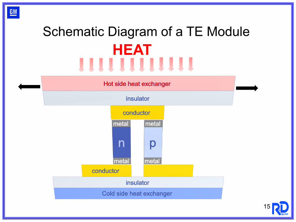
Schematic Diagram of a TE Module HEAT
Exhaust Heat - City Driving Cycle
0
10
20
30
40
50
60
70
80
0 500 1000 1500 2000 2500
Test Time (s)
kW
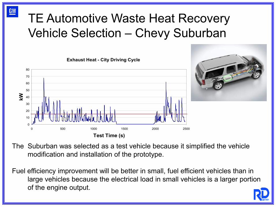
The Suburban was selected as a test vehicle because it simplified the vehicle modification and installation of the prototype.
Fuel efficiency improvement will be better in small, fuel efficient vehicles than in large vehicles because the electrical load in small vehicles is a larger portion of the engine output.
TE Automotive Waste Heat Recovery Vehicle Selection – Chevy Suburban
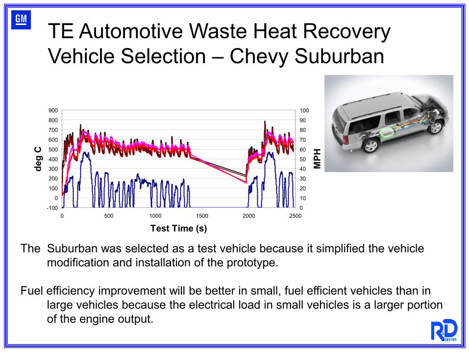
-100
0
100
200
300
400
500
600
700
800
900
0 500 1000 1500 2000 2500
Test Time (s)
deg
C
0
10
20
30
40
50
60
70
80
90
100
MPH
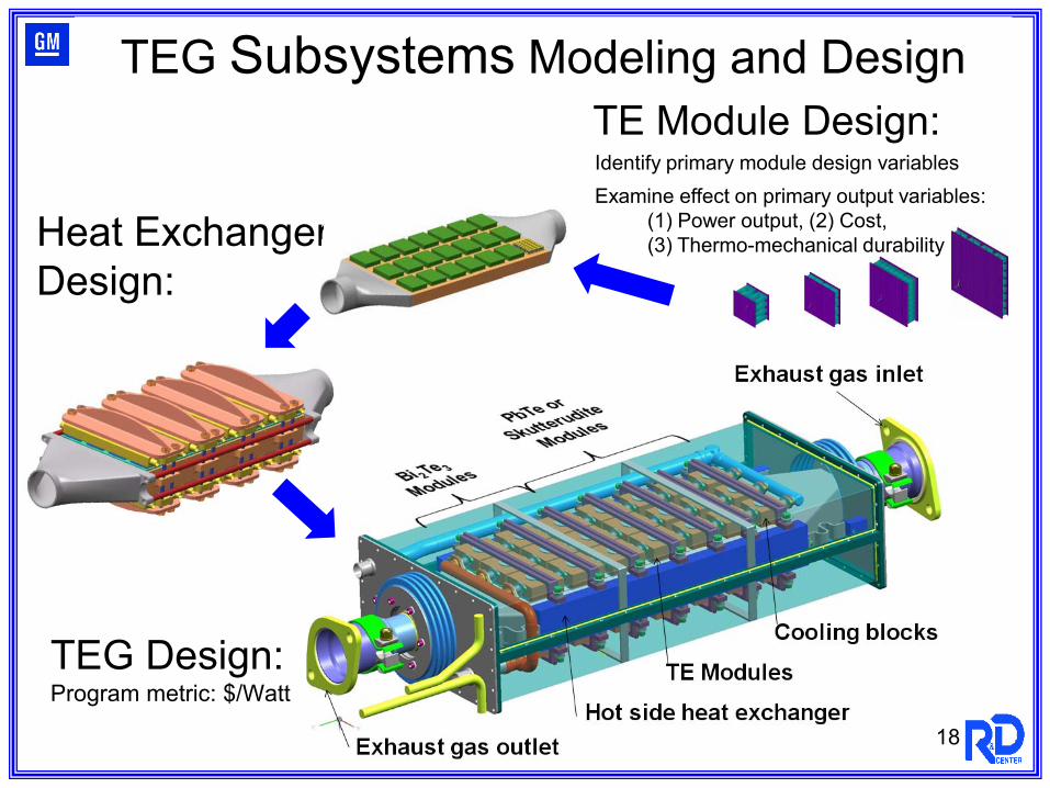
TE Module Design:
Heat ExchangerDesign:
18
TEG Subsystems Modeling and Design
Identify primary module design variablesExamine effect on primary output variables:
(1) Power output, (2) Cost, (3) Thermo-mechanical durability
TEG Design:Program metric: $/Watt
19
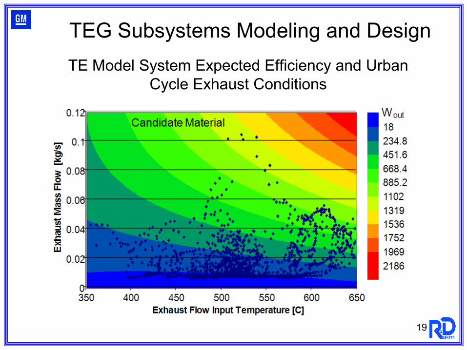
TEG Subsystems Modeling and DesignTE Model System Expected Efficiency and Urban
Cycle Exhaust Conditions
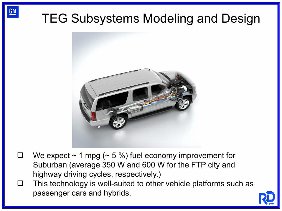
We expect ~ 1 mpg (~ 5 %) fuel economy improvement for Suburban (average 350 W and 600 W for the FTP city and highway driving cycles, respectively.)
This technology is well-suited to other vehicle platforms such as passenger cars and hybrids.
TEG Subsystems Modeling and Design
21
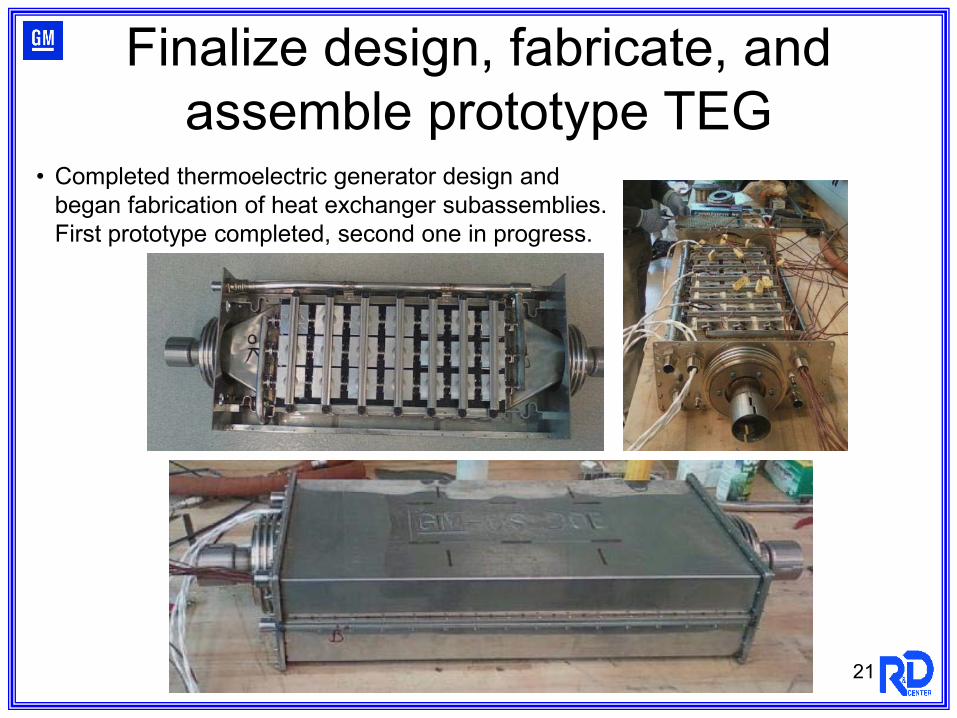
• Completed thermoelectric generator design and began fabrication of heat exchanger subassemblies.First prototype completed, second one in progress.
Finalize design, fabricate, and assemble prototype TEG
22
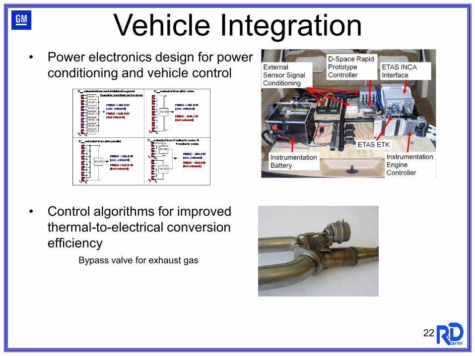
• Power electronics design for powerconditioning and vehicle control
• Control algorithms for improved thermal-to-electrical conversion efficiency
Bypass valve for exhaust gas
Vehicle Integration
23
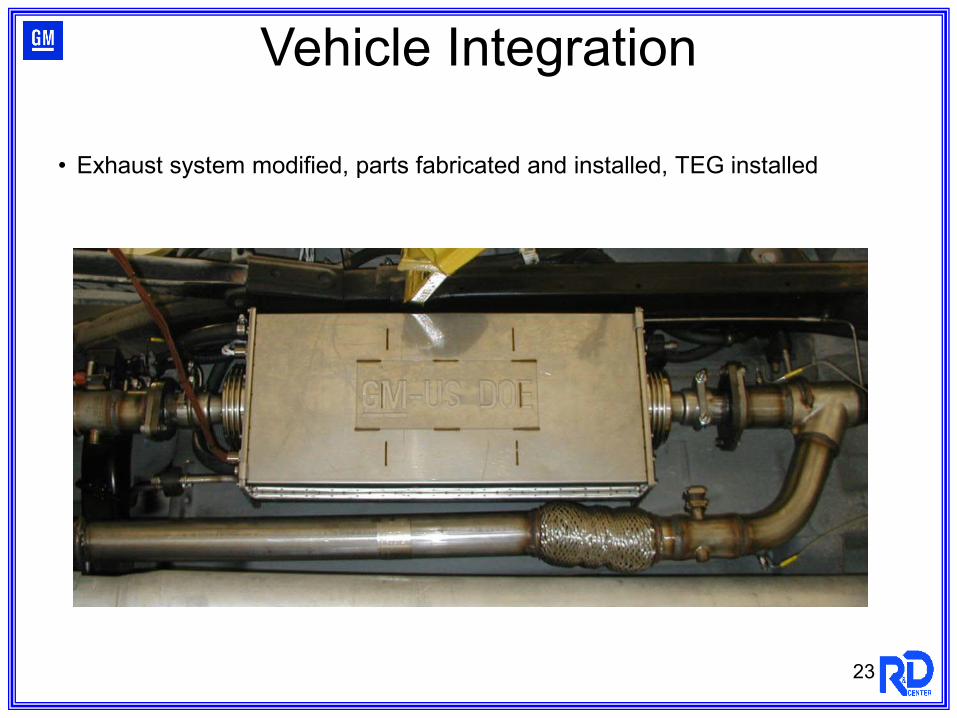
• Exhaust system modified, parts fabricated and installed, TEG installed
Vehicle Integration
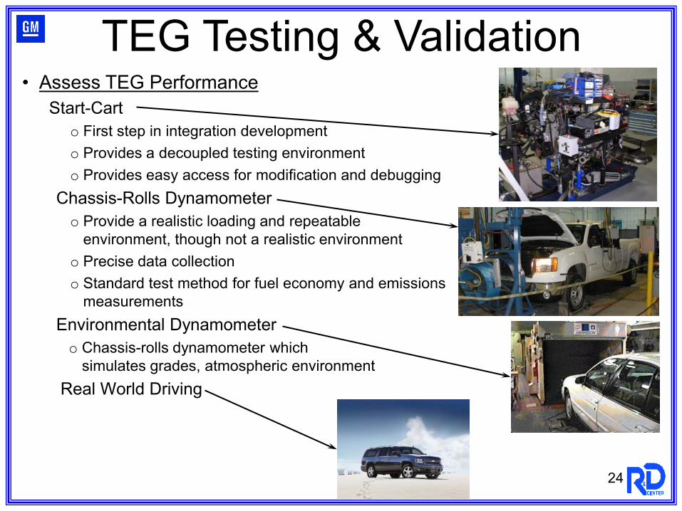
• Assess TEG PerformanceStart-Cart
o First step in integration developmento Provides a decoupled testing environmento Provides easy access for modification and debugging
Chassis-Rolls Dynamometero Provide a realistic loading and repeatable
environment, though not a realistic environmento Precise data collectiono Standard test method for fuel economy and emissions
measurementsEnvironmental Dynamometero Chassis-rolls dynamometer which
simulates grades, atmospheric environmentReal World Driving
24
TEG Testing & Validation
25
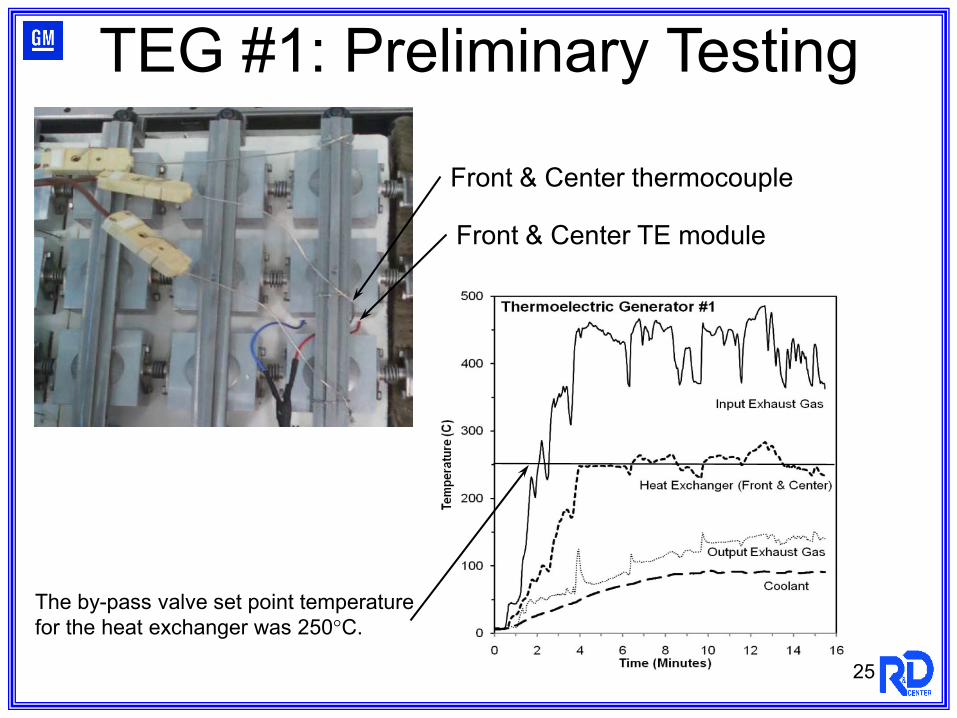
TEG #1: Preliminary Testing
Front & Center thermocouple
Front & Center TE module
The by-pass valve set point temperature for the heat exchanger was 250°C.
26
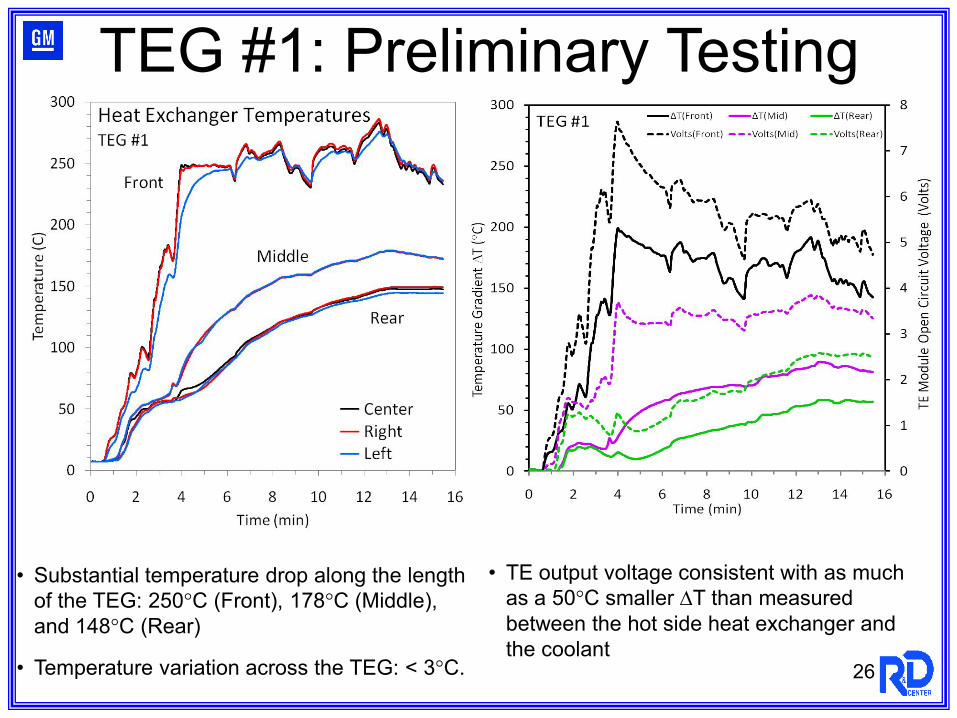
TEG #1: Preliminary Testing
• Substantial temperature drop along the length of the TEG: 250°C (Front), 178°C (Middle), and 148°C (Rear)
• Temperature variation across the TEG: < 3°C.
• TE output voltage consistent with as much as a 50°C smaller ∆T than measured between the hot side heat exchanger and the coolant
27
• Complete assembly of TEG #2 with full electrical system components (42 TE modules).
• Finalize and implement vehicle integration with TE waste heat recovery system and complete the necessary vehicle modifications.
• Develop higher temperature TE modules for TEG #3.
• Carry out dynamometer tests and proving ground tests for vehicle equipped with the TE waste heat recovery system.
• Demonstrate fuel economy gain using TE waste heat recovery technology.
Future Work

28
• Prototype TEGs are being assembled and installed on the test vehicle.
• Vehicle modifications and system integration are being completed as the TEGs are installed on the vehicle.
• Improvements in the performance of TE materials have been achieved, particularly for Skutterudites.
• Skutterudite modules are being developed for the final prototype TEGs.
Summary