thesis fernando pizarro quintanar 05122014
TRANSCRIPT

DEVELOPMENT OF A COMPREHENSIVE DATABASE
AND SELECTION MODEL FOR OPTIMUM
RETAINING WALL. CONSTRUCTION,
COST AND PRODUCTION
by
FERNANDO PIZARRO QUINTANAR
Presented to the Faculty of the Graduate School of
The University of Texas at Arlington in Partial Fulfillment
of the Requirements
for the Degree of
MASTER OF CIVIL ENGINEERING
THE UNIVERSITY OF TEXAS AT ARLINGTON
May 2014

Copyrigght © by Fern
All Rig
ii
ando Pizarro
ghts Reserve
o Quintanar 20
ed
014

iii
Acknowledgements
I would like to extend my sincere and deepest gratitude to my advisor Dr. Mohammad
Najafi, for his guidance and constant support throughout the conception and development
of this research study. His positive attitude and focus in advancements and development
in construction processes inspired me to develop this document that can serve as a tool
for other engineers in need, thus improving the engineering profession, his long-life goal.
I am grateful to Dr. Laureano Hoyos and Dr. Sahadat Hossain for readily
accepting to serve in my dissertation committee as well as for their inspiring and
extraordinary courses I had the honor to be enrolled in. They give their classes with care
and detail, allowing the distance students to follow the courses as if they were present,
increasing my interest in geotechnical engineering to levels never experienced in my
previous academic and professional life.
I am also thankful to the Civil and Environmental Engineering staff, which so
many times helped me with their friendly and helpful approach in every administrative
step during the completion of my Degree at the University of Texas at Arlington.
Particularly, for their understanding and support during the hard times I had to go through
in Fall 2012 and Spring 2013.
I am deeply grateful to my Company, Ferrovial-Agroman, for their support and
trust during the completion of this degree, for their vision of a better future and their belief
on the important of the training, education, innovation and talent development. I am
especially thankful to Mr. Mario Mostoles and Mr. Carlos Fernandez P.E. as well as to all
my team, who works restless to ensure that our footprint in Texas excels in quality and
social awareness while coping with my times of study and classes at the UTA. I am also
grateful to all the colleagues that participated during the interviews and survey processes

iv
as well as the field personnel and companies included in the field observations. Their
input has been proven to be invaluable for the completion of this Thesis.
I am grateful to my loving wife Leticia, for being the perfect partner in the
challenges of life, for her endless support, for her confidence, her trust and efforts in
granting me the time needed for these studies during long days and nights of study with
her by my side.
Also, my special thanks are due to all my American and Spanish friends, who
have always supported and encouraged me for successful completion of any challenge I
have ever faced.
Finally, words are not enough to express my gratitude and love to my father
(Miguel Pizarro Barranquero) and my mother (Rosario Quintanar Sanchez-Alarcos), for
giving me the gift of life. For their loving care, education, guidance, trust and support, for
the values of effort, work, empathy and the warmth of a home that I always love to come
back to. They provided me with a path to follow, with an example of excellence in life,
with a model to create a happy and healthy family and with guidance on how to make a
difference in life. This gratitude is extended to my brother, sister and rest of my family, for
their unconditional love, for the laughs and mutual admiration.
April 16, 2014

v
Abstract
DEVELOPMENT OF A COMPREHENSIVE DATABASE
AND SELECTION MODEL FOR OPTIMUM
RETAINING WALL. CONSTRUCTION,
COST AND PRODUCTION
Fernando Pizarro Quintanar
The University of Texas at Arlington, 2014
Supervising Professor: Mohammad Najafi
Retaining walls are earth retention structures that are essential in the majority of
the construction projects for the overall project’s engineering performance, as well as its
budget and schedule. These elements constitute a key role in urban development,
industrial facilities and civil projects as evidenced by the more than 170 million of square
feet being constructed per year in the United States. The current market conditions, as
well as the advances in the technology and knowledge associated to these elements,
determine the need for accurate decision making processes that lead to optimum
retaining walls in terms of applicability, cost and production rates.
More than 50 types of retaining walls are currently available in the market, having
each one of them further subdivisions depending on the materials and configurations
being used. Thus, properly developed databases and decision models are highly
important to make accurate selections.
Each type of retaining wall present a unique set of advantages and disadvantages,
construction processes, equipment and material needs as well as limitations. These

vi
particular features of each are identified and analyzed in order to determine those factors
driving the selection of each type.
Literature references in retaining wall design and construction are extensive and
complete. However, no single source provides a comprehensive guideline for the
analysis of the different types of retaining walls in order to make a comparative analysis
that can lead to a selection decision. This lack of references is greater in regards to unit
costs, production rates and construction issues mostly caused by the commercial
implications of disclosing them. Specialized references consider field observation and
record keeping as the most adequate approach to determine accurate costs and
production rates.
Previous studies have attempted to develop wall selection models that use
previous experiences to determine the most appropriate retaining wall type for a specific
set of needs and constraints. However, these references failed to include three key
factors such as direction of construction, unit cost and production rates. The selection
model developed in this research follows an Imperialist Competitive Algorithm (ICA),
based on a knowledge database and incorporating specific decision driving parameters
for each wall type.
Successful experiences in previous projects do not ensure proper outcomes in
the future ones and therefore only a project specific analysis can provide the basis for the
reduction of the risk associated with the wall selection. This research analyzes and
present those considerations that determine the adequacy of each type of wall and the
factors that affect their performance during and after construction.
The results from the literature review, analysis of previous experiences, surveys
and interviews to expert subjects are supplemented with field observations of heavy civil
construction Projects in the DFW area to determine typical unit costs, production rates

vii
and construction issues. While the identified construction issues can serve as the base
for the developments of specially tailored QA/QC programs, the unit costs and production
rates can be used as a database for future preliminary studies and are built into the
decision model developed in this research. The model is validated using four known walls
as input in order to compare the solutions returned by the model against the real-world
constructed ones in terms of wall type. Additionally, subject experts are used to further
validate the accuracy of the model to replicate expert reasoning process.
The data obtained during the different collection phases, as well as the analyses
performed can serve as a starting point for future preliminary studies. The selection
model developed ins this research can be used to determine the most adequate retaining
wall for a specific set of constraints, where limited information is available.

viii
Table of Contents
Acknowledgements ............................................................................................................. iii
Abstract ............................................................................................................................... v
List of Illustrations .............................................................................................................. xii
List of Tables ..................................................................................................................... xv
Chapter 1 Introduction ......................................................................................................... 1
1.1 Topic ......................................................................................................................... 2
1.1.1 Scope and Limitations ......................................................................... 2
1.2 Need Statement ........................................................................................................ 3
1.3 Research Objectives ................................................................................................ 6
1.4 Expected Outcome ................................................................................................... 7
1.5 Thesis Organization .................................................................................................. 7
Chapter 2 Background and Literature Review .................................................................... 9
2.1 History of Retaining Walls ........................................................................................ 9
2.2 Literature Research and Background Review ........................................................ 10
2.2.1 Retaining Wall Types, advantages and disadvantages .................... 11
2.2.1.1 Cantilever Reinforced Concrete .................................................. 13
2.2.1.2 Mechanically Stabilized Earth (MSE) .......................................... 14
2.2.1.3 Drill Shafts ................................................................................... 14
2.2.1.4 Soil/Rock Nail .............................................................................. 15
2.2.1.5 Tie Back ...................................................................................... 15
2.2.1.6 Summary of Retaining Wall Features ......................................... 17
2.2.2 Retaining Wall Construction: Phases, Equipment and
Materials. ............................................................................................. 20
2.2.2.1 Excavation .................................................................................. 22

ix
2.2.2.2 Drilling ......................................................................................... 23
2.2.2.3 Reinforcement Placement........................................................... 26
2.2.2.4 Concrete, grout and shotcrete placement ................................... 28
2.2.2.5 Backfilling operations .................................................................. 31
2.2.2.6 Stressing operations ................................................................... 33
2.2.3 Retaining Wall Construction Cost and Production Rates ................. 34
2.2.3.1 Retaining Wall Construction Cost ............................................... 35
2.2.3.2 Retaining Wall Construction Production Rates ........................... 37
2.2.4 Retaining Wall Selection Process ..................................................... 39
2.2.4.1 Retaining Wall Selection Models ................................................ 40
2.2.4.2 State Guidelines for retaining wall selection ............................... 43
2.2.4.3 Optimization and parametric design ........................................... 44
2.2.5 Analysis of 4 known walls ................................................................. 45
2.2.5.1 Wall 1 .......................................................................................... 46
2.2.5.2 Wall 2 .......................................................................................... 48
2.2.5.3 Wall 3 .......................................................................................... 52
2.2.5.4 Wall 4 .......................................................................................... 55
2.2.6 Conclusions and findings of literature research and
background review ............................................................................... 57
Chapter 3 Methodology ..................................................................................................... 61
3.1 Definition of the research and phases of data collection ........................................ 61
3.2 Background and literature review ........................................................................... 64
3.3 Surveys and Interviews to expert subjects ............................................................. 64
3.3.1 Survey to Eight Expert professionals. ............................................... 67
3.3.2 Interview to Five Expert Engineers. .................................................. 69

x
3.4 Field Observations .................................................................................................. 72
3.4.1 Observation 1: Cast in Place Cantilever Wall ................................... 75
3.4.2 Observation 2: Mechanically Stabilized Earth (MSE) ....................... 77
3.4.3 Observation 3: Drill Shaft Wall .......................................................... 79
3.4.4 Observation 4: Rock Nail Wall .......................................................... 82
3.4.5 Observation 5: Tie Back Wall ............................................................ 84
3.5 Data organization, analysis and conclusions for model and database .................. 86
3.5.1 Summary of the Survey to Eight Expert professionals...................... 86
3.5.1.1 Identified trends and observations .............................................. 87
3.5.2 Summary of the Interviews to Five Expert professionals. ................. 95
3.5.2.1 Identified trends and observations .............................................. 95
3.5.2.2 Driving factors for wall determination .......................................... 96
3.5.2.3 Retaining Wall types ranking in terms of difficulty,
cost and duration of construction ..................................................... 97
3.5.2.4 Identification of the “no-go” conditions based on the
interviews results .............................................................................. 98
3.5.3 Summary of the Field Observations and comparison with
the survey results. .............................................................................. 106
3.5.4 Selection of limiting height, typical unit cost and
production rates for the selection model. ........................................... 107
Chapter 4 Results ........................................................................................................... 110
4.1 Retaining Wall Database ...................................................................................... 111
4.2 Retaining Wall Selection Model (RWSM) ............................................................. 113
4.2.1 Structure of the RWSM ................................................................... 113

xi
4.2.2 Determination of the selection drivers and decision
parameters ......................................................................................... 114
4.2.3 RWSM Development and Implementation into Flowchart
Model ................................................................................................. 115
Chapter 5 Discussion of Results ..................................................................................... 118
5.1 Analysis of the Retaining Wall Database ............................................................. 118
5.2 Validation of the Retaining Wall Selection Model (RWSM) .................................. 121
5.2.1 Model Validation by use of 4 Known Walls ..................................... 122
5.2.1.1 Known Wall #1 Verification ....................................................... 122
5.2.1.2 Known Wall #2 Verification: ...................................................... 123
5.2.1.3 Known Wall #3 Verification: ...................................................... 124
5.2.1.4 Known Wall #4 Verification: ...................................................... 124
5.2.2 Model Validation by use of expert’s judgment ................................ 125
5.2.3 Summary of the RWSM Validation process .................................... 127
5.3 Analysis and Evaluation of the Wall Selection Model (RWSM) ............................ 128
Chapter 6 Conclusions and Recommendations for Future Research ............................ 130
6.1 Summary and Conclusions ................................................................................... 130
6.2 Recommendations for Future Research .............................................................. 133
Appendix A Abreviations used in this Thesis .................................................................. 134
Appendix B Completed Forms of Surveys performed to Expert Subjects ...................... 136
Appendix C Completed Forms of Interviews performed to Expert Subjects ................... 153
Appendix D Completed Retaining Wall Selection Model. Flowchart. ............................. 169
References ...................................................................................................................... 171
Biographical Information ................................................................................................. 177

xii
List of Illustrations
Figure 2-1 Layout of the Eastern Stairway of Apadana ...................................................... 9
Figure 2-2 (a) Inuit building igloo in Lappland and (b) Angolan muhimba house ............. 10
Figure 2-3 Aerial Picture of LBJ Project. March 2013 ....................................................... 12
Figure 2-4 Different types of wall constructed in an specific location ............................... 13
Figure 2-5 Retaining wall categories organized by increasing needs for specialized
equipment and materials ................................................................................................... 20
Figure 2-6 Retaining wall use distribution for TxDOT Projects from 08 to 07-2007 ......... 21
Figure 2-7 Preparatory excavation process for (a) Rock Nail and (b) cantilever wall. ..... 23
Figure 2-8 Underdrain for MSE Wall drainage and subgrade preparation ....................... 23
Figure 2-9 (a) Drilling operation for Tie Back and Rock Nail walls. (b) Detail of drilled
holes prior to reinforcement placement and grout injection .............................................. 24
Figure 2-10 (a) Drilling operation for Rock Nail walls and (b) Detail of drilled holes
inclination check prior to reinforcement placement and grout injection ............................ 24
Figure 2-11 Drilling operation for drill shaft walls. (a) drill shaft wall executed in front of a
nail wall and (b) protective cage for the operator. ............................................................. 25
Figure 2-12 Hydraulic hoe loading spoils in a rigid frame dump truck .............................. 25
Figure 2-13 (a) Rebar cage in drill shaft prior to concrete placement. (b) Rebar placement
for cantilever cast in place wall stem ................................................................................ 26
Figure 2-14 Galvanized straps placed over the granular backfill for reinforcement ......... 27
Figure 2-15 Commercial tie back anchor system ............................................................. 28
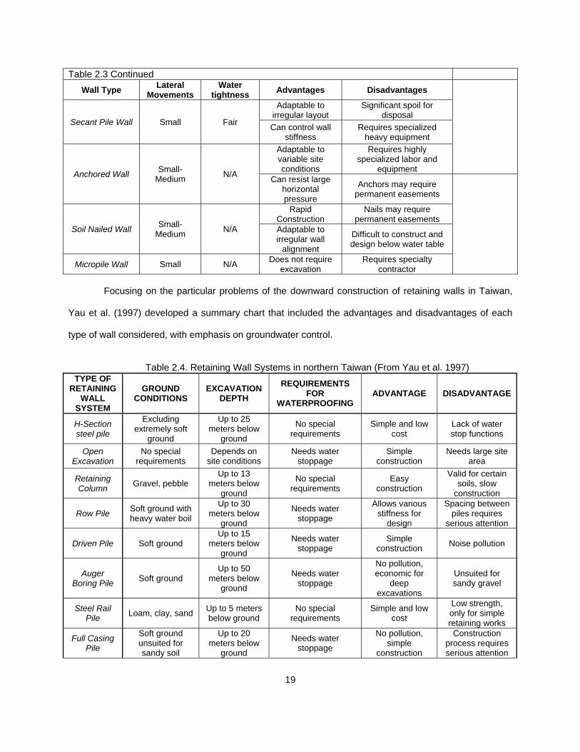
Figure 2-16 Grout mixer system used to on-site grout production ................................... 29
Figure 2-17 Nozzle operator placing shotcrete in rock nail wall (wet) .............................. 29
Figure 2-18 (a) Concrete placed in cantilever wall with bucket and (b) drill shaft with
hopper ............................................................................................................................... 30

xiii
Figure 2-19 (a) Detail of tremie tube inside of rebar cage to place the concrete (b)
concrete Batch Plant ......................................................................................................... 30
Figure 2-20 Backfilling operation in MSE Wall .................................................................. 32
Figure 2-21 (a) Joint materials and (b) detail of weep-hole device to install in MSE ........ 32
Figure 2-22 Stressing operation for (a) threaded bar tie back wall and (b) low relaxation
steel strands ...................................................................................................................... 33
Figure 2-23 Steel, formwork and concrete labor cost per CY Vs. Wall Height ................. 36
Figure 2-24 Influence of design sliding Safety Factor in Cantilever wall unit costs .......... 37
Figure 2-25 Sources of Information for Wall selection ...................................................... 38
Figure 2-26 Retaining Wall Selection System (RWSS) developed by Yang (2004) ......... 41
Figure 2-27 Yau’s (2002) algorithm for wall selection for deep excavations in Taiwan. ... 41
Figure 2-28 Temporary Wall selection for Metropolitan Expressway Public .................... 45
Figure 2-29 Typical sections and wall properties for Wall 1 ............................................. 46
Figure 2-30 (a) Cast in place wall concrete placement and (b) subgrade preparation ..... 47
Figure 2-31 Rock Nail drilling and drainage operations .................................................... 49
Figure 2-32 Typical sections and wall properties for Wall 2 ............................................. 50
Figure 2-33 Epoxy coated protection for soil/rock nail bars in Wall 2 ............................... 51
Figure 2-34 Wall 3 (a) shaft and (b) capping beam reinforcement ................................... 52
Figure 2-35 Wall 3 geotechnical configuration for calculations......................................... 53
Figure 2-36 (a) Wall 3 drill shafts with tie backs and (b) typical section .......................... 53
Figure 2-37 (a) Wall 3 anchor testing and (b) load-pressure curve .................................. 54
Figure 2-38 Wall 4 MSE Wall Typical section ................................................................... 55
Figure 3-1 Research Methodology Process. .................................................................... 63
Figure 3-2 Observed Wall #1 ............................................................................................ 76
Figure 3-3 Observed Wall #2 ............................................................................................ 77

xiv
Figure 3-4 Observed Wall #3 ............................................................................................ 79
Figure 3-5 Observed Wall #4 ............................................................................................ 82
Figure 3-6 Observed Wall #5 ............................................................................................ 84
Figure 3-7 Graphical representation of the rankings shown in Table 3.16 ....................... 98
Figure 4-1 Detail of the two initial steps of the RWSM ................................................... 116
Figure 4-2 Detail of one section of the selection model for upward wall <10 ft. ............. 116
Figure 4-3 Detail of additional notes in the selection model for upward wall <10 ft. ...... 117
Figure 5-1 RSMeans City Cost Index Year 2013 ............................................................ 119
Figure 5-2 Model Validation for Known Wall #1 .............................................................. 122
Figure 5-3 Model Validation for Known Wall #2 .............................................................. 123
Figure 5-4 Model Validation for Known Wall #3 .............................................................. 124
Figure 5-5 Model Validation for Known Wall #4 .............................................................. 125
Figure 5-6 Model Validation for Expert from Survey #1 .................................................. 127

xv
List of Tables
Table 2.1 Classification of Retaining Walls by Configuration and Materials .................................. 11
Table 2.2 Matrix for Fill Walls ........................................................................................................ 17
Table 2.3 Matrix for Cut Walls ....................................................................................................... 18
Table 2.4. Retaining Wall Systems in northern Taiwan ................................................................. 19
Table 2.5 Retaining Wall distribution for TxDOT Projects from August 1 to July 2007 ................ 21
Table 2.6 Summary of Constraints and Resulting requirements for backfill ................................. 31
Table 2.7 Unit cost distribution for known Wall 1 .......................................................................... 48
Table 2.8 Recommended nominal factored presumptive
pullout resistances or factored bond strengths for rock-nail wall design ....................................... 49
Table 2.9 Unit cost distribution for known Wall 2 ........................................................................... 51
Table 2.10 Unit cost distribution for known Wall 3 ........................................................................ 55
Table 2.11 Unit cost distribution for known Wall 4 ........................................................................ 57
Table 2.12 Summary of Constraints and features for the Walls analyzed ..................................... 58
Table 2.13 Summary of Unit Costs and Productionrates for known Walls ................................... 58
Table 2.14 Comparison between Unit Costs obtained from different sources .............................. 60
Table 3.1 Summary of Preliminary Survey performed on 11/15/2013 ........................................... 81
Table 3.2 Driving factors identified by the three consulted experts ............................................... 66
Table 3.3 Sample Retaining Wall Selection Survey Form ............................................................. 68
Table 3.4 List of Interviewed Experts ............................................................................................. 70
Table 3.5 Sample Retaining Wall Selection Interview Form .......................................................... 70
Table 3.6 Retaining Wall Types selected for the field observations .............................................. 73
Table 3.7 Development of Unit cost for observed Cast In Place Cantilever Wall .......................... 76
Table 3.8 Development of Unit cost for observed MSE Wall ......................................................... 78
Table 3.9 Development of Unit cost for observed Drill Shaft Wall ................................................. 80

xvi
Table 3.10 Development of Unit cost for observed Rock Nail Wall .............................................. 83
Table 3.11 Development of Unit cost for observed Tie Back Wall ................................................ 85
Table 3.12 Analysis of expert’s rates and calculation
of nominal values for selection model ........................................................................................... 88
Table 3.13 Summary of information obtained during the Surveys
to the eight experts ........................................................................................................................ 90
Table 3.14 Areas where information is insufficient for the experts ................................................ 96
Table 3.15 Driving factors for wall determination .......................................................................... 96
Table 3.16 Ranking of walls based in terms of difficulty, cost and
duration of construction .................................................................................................................. 97
Table 3.17 “No-go” conditions for each retaining wall type based
on the interview’s results ................................................................................................................ 99
Table 3.18 Summary of information obtained during the
Interviews to the five experts engineers ...................................................................................... 101
Table 3.19 Summary of Unit Costs and Production Rates .......................................................... 109
Table 3.20 Unit Costs and Production Rates to be used in the selection model ......................... 111
Table 3.21 Limiting height for the different wall types .................................................................. 111
Table 4.1. Table of typical values of height, unit cost and
production rates for the wall types used in the RWSM ................................................................ 114
Table 4.2. Table of typical construction issues for the different
types of retaining wall for implementation in QC/QA plans .......................................................... 115
Table 4.3. Selection Drivers for each direction of construction .................................................... 117

1
Chapter 1
Introduction
Retaining wall design and construction has evolved and been developed greatly in the last
decades due to the increasing need of optimizing the space and reducing the material consumption.
ASCE (2013) calculated that the current earth retaining market of the US exceeds 170 million square feet
per year. Additionally, this has been catalyzed by the need of reducing the environmental impact of
construction projects. Based on an ASCE Seminar (2013), there are over 50 different retaining systems.
However, each type of wall involves different advantages and disadvantages that need to be evaluated
when deciding the wall type for a particular set of conditions and constraints. A proper selection of the
type of retaining wall to be used is key for the overall success of any construction project.
Wall types vary among different categories, having unit costs spanning from less than $20 to in
excess of $250/sq. ft. Selecting the most technically appropriate and cost-effective system is often critical
to project cost and schedule. An incorrect wall system selection can lead to delays and/or cost overruns.
Most Engineers, contractors and construction management personnel lacks the required specialized
knowledge to select the most appropriate wall for an intended location. (ASCE, 2013)
During the design and construction process of the retaining walls, mostly for nailed and
mechanically stabilized earth walls, different companies and agents interact between the different phases.
Coordination and consistency among them is essential to achieve the desired retaining wall built. Also,
production and cost control is key for the overall output of the project where the walls are constructed and
therefore, they will be analyzed in this Report.
The equipment involved in the construction of some of the types of retaining walls constitutes the
highest cost incurred and determines the production rate to be achieved. Some of this machinery is very
specific and operating them properly requires a deep understanding of the process and the optimization
of the cycles of work. Production cost and rates will be analyzed and discussed for the different types of
retaining walls reviewed.
The privileged position where the author finds himself while developing this thesis will be used to
obtain data from retaining walls under construction, expert designers, construction companies,
specialized subcontractors, developers and public owners. Currently participating in a heavy civil

2
transportation project, some of the walls being constructed in the DFW area will be used as a data pool
for both input for the decision model and also as a check for the trials runs to be executed with it. By
introducing the parameters for these walls in the model, the returned wall type will be compared with the
one executed to determine the accuracy and applicability of the selection process.
1.1 Topic
The proposed Thesis will focus on retaining wall construction. Starting with a research effort to
identify the different types of retaining walls used on civil construction and transportation projects, the
main ones will be selected. Then, a comparison will be performed, in terms of applicability, advantages
and disadvantages. Additionally, standard cost and production ratios will be developed based on field
observation, reference analysis, interviews and surveys to personnel from specialized companies.
By analyzing and comparing all the data obtained in these previous phases, a wall selection
guideline and a retaining wall database will be developed. This model will consist in a “wall selection
matrix” that guides the selection process in a flowchart with Yes/No questions, leading to the optimum
type of wall for a given set of constraints.
1.1.1 Scope and Limitations
Three main phases will be completed during the development of this Thesis.
First an extensive research will be performed in order to identify not only which types of retaining
walls are currently available for civil construction projects but also which ones are the most
common, selecting these for the next phases of the Thesis. This will include not only a literature
research but also an analysis of real projects.
Second, these selected walls will be analyzed in order to determine their advantages and
disadvantages under certain conditions, their applicability under the different design parameters,
their unit cost and production rates. A retaining wall database will be developed.
Lastly, all this information will be built into a decision model that will later be evaluated by using
three know existing retaining walls.

3
This study will include the review of the majority of the types of retaining walls being available for
heavy civil construction under permanent conditions. However, it will focus on those main types being
used such as cantilever reinforced concrete, tie back, rock/soil nails, drill shafts and mechanically
stabilized earth. Although some of the wall types are both used as permanent and temporary walls, only
permanent construction will be considered.
Specific needs and locations might require sequences of different retaining walls such as land
developments or landfills. In those cases where the height to be retained is excessive and space is
available, multiple level retaining walls can constitute a viable solution with no more than three tiers under
normal circumstances (Jalla, 1999).
Plenty of documentation and reference is available regarding wall design and construction.
However, production rates and unit costs are parameters where the commercial interests pose an
obstruction for their public distribution. In order to counteract against this trend, research, investigation,
surveys and observations will be performed in this research in order to develop these rates. Although
every project requires an specific cost and productivity analysis, the values presented here can serve as
a starting point for those engineer in need during preliminary or feasibility studies.
1.2 Need Statement
Determining the most appropriate retaining wall to be constructed in a particular location or
project is a complicated task that involves a thorough and educated decision process. Several
considerations are required to be comprehensively analyzed in order to achieve the desired result in
terms of safety, quality, budget and schedule.
The unfavorable current market conditions and the reduced work available for the construction
companies, create a difficult environment where the competition between companies is harder than in
previous decades. Project owners benefit from these conditions, via reduced bids, PPP (Public-private-
partnership) or concessions. Therefore, proper selection of the wall type and an optimized construction
process is essential for any Engineer involved in the current construction market where the room for
inefficiencies and corrections has been reduced to inexistent.

4
Current heavy civil construction projects include a combination of the different types of retaining
walls, each one of them determined due to its specific location or use. Temporary or permanent use,
space available for their construction, rate of production needed and loads to be withstood determine the
best type of wall to use (Hess and Adams, 1995).
Retaining wall design and construction has been optimized in all phases of the process due to the
scientific and technological developments. This was partly triggered by an increasing need of reducing
the space and material consumption. In addition to this, the increasing efforts towards more sustainable
civil construction, forced engineers and builders to develop new systems and configurations that reduce
the construction impact. Despite the developments, each type of wall involves a complicated set of
advantages and disadvantages that need to be evaluated in order to identify the best wall for a particular
set of conditions and constraints. A proper selection of the type of retaining wall to be used is instrumental
for the final success of any civil construction project, especially in the transportation field.
A comprehensive guide and database of retaining walls does not currently exist as evidenced by
the literature review. The research performed shows that most wall type selections are performed based
on subjective previous experience (Hancher et al. 1992). The development of a scientifically based
database of those features that affect in the wall selection is a necessary step towards more optimized
studies in preliminary studies and feasibility analyses.
Every designer and/or developer needs to evaluate which type of retaining wall is most
appropriate for a particular use or location. Based on the references investigated in Section 2, there is no
comprehensive guideline tool to help making this determination. Currently, most fields of retaining wall
design and construction have been widely investigated, and publications are available in all formats such
as books, papers, journals, thesis and dissertations. However, each one of these documents focus are
individually focused in design, construction, monitoring, evaluation, production or cost. Decision models,
with or without expert systems, are not available for the general use (Yang, 2004).
Only an extensive experience, supplemented with multidisciplinary design teams can gather the
required information to determine which wall is the most adequate for a particular need. Irrespectively of
the degree of experience of an engineer, it is always required to receive input from other engineers. Thus,

5
a pre-constructed selection model appears as a good tool to provide the engineers with more information
and help during the decision process (Yang et. al 2003).
Literature and previous experiences and developments in regards to the retaining wall selection
process have been researched. No single source has been identified to provide a sufficiently
comprehensive system that is adapted to current needs and that is available to the general engineering
practice. Although expert systems have been used in the past for selection and preliminary design of
retaining walls (Lee 1989, Ikoma 1992 and Yang 2003), these research documents were developed at
least 10 years ago, thus losing the potential of current programming methods and technology evolution.
All the previous experiences consisted in computer based models. These required of an
extensive knowledge of programming language and database development. Most engineers in need of
determining a certain type of wall would not have the time nor the skills required to make use of these
tools.
Additionally, none of the methods identified during the literature research included three of the
most important factors in the retaining wall decision process: cost, production rate and direction of
construction (upward or downward). Just by the use of these three parameters, the available options can
be drastically reduced, therefore easing the process of selecting among fewer potential types.
Previous references have established the need of developing knowledge-based systems in order
to better determine the most adequate solutions for the different project needs. Both Hancher et. al (1992)
and Chong (2005) concluded that rather than relying on pure experience or improperly appraised
historical records, a comprehensive research would lead to more accurate data and decision making
processes. Yang (2004) research showed that some construction problems cannot be represented nor
resolved with the use of conventional scientific algorithms, thus the need of different systems and
approaches. Although experience-oriented problems represent a suitable alternative where solutions are
obtained by previous experiences, Hess and Adams (1995) indicated that the majority of the engineers
tend to restrict themselves to select retaining wall types that they have experience with.
Following these references as a starting point, the present research will gather information from
multiple sources such as literature, field observations, expert surveys and interviews to combine them into
a knowledge based database and a decision model.

6
1.3 Research Objectives
The goal of this research is to perform a comprehensive analysis of the current “state of the art” in
retaining wall construction, focusing on those configurations that are most used in civil construction.
Based on this analysis, the main types are to be selected for further study and identification of their unit
cost and production rates under normal circumstances. Lastly, based on all information obtained from the
literature research, and additional collected data, a wall selection model and a retaining wall database will
be developed.
Five main objectives are established to be accomplished at the completion of the Thesis:
Analyze the currently available retaining wall types in heavy civil construction, identifying their
applicability, advantages and disadvantages.
Identify the main types of retaining walls for the aforementioned heavy civil construction and
transportation projects based on the previous analysis,
Collect accurate information regarding limiting heights, construction issues, driving parameters,
cost and production rates by performing observations, research, interviews and surveys that can
serve as a starting point for retaining wall selection and preliminary studies, therefore developing
a database of retaining wall information.
Develop a comprehensive database that provides adequate information for use in preliminary
studies and for the determination of the most suitable wall type for a certain project needs,
including limiting heights, specific features, frequent construction issues, unit costs and
production rates.
Develop a set of guidelines for retaining wall selection based on a given set of constraints, by
constructing a sequential decision model based on a flowchart structure.
At the completion of this Thesis, the developed model will allow a designer or construction
engineer to identify the optimum retaining wall type to fulfill his/her needs based on the particular set of
conditions of the wall at hand.

7
1.4 Expected Outcome
The final result of the work to be performed during the completion of this Thesis will be a
comprehensive decision model and a retaining wall database that includes unit costs, production rates,
advantages and disadvantages for each type. The model will result in a user-friendly set of guidelines that
by means of a flowchart can be used by any Engineer to determine which retaining wall type is the most
suitable for a certain location.
The data presented in the database will serve as an starting point for preliminary studies and
feasibility analysis where limited information is available and few references are available to obtain typical
values for each wall type.
This model will be based a series of questions/answers that will guide the decision process to the
optimum solution. These questions will be developed based on the information sources that will be
utilized such as literature review, background studies, observations, surveys and interviews. The thinking
process followed by experienced geotechnical designers and retaining wall builders will be implemented
into the model so it can be used by other engineers in need.
These wall selection guidelines will serve as a preliminary filter for those engineers that face the
problem of which wall to design in detail for a particular location. Current market conditions do not allow
engineers to pre-dimension 15 wall types to determine the optimum solution, thus the usefulness of the
proposed model which can reduce the feasible options to 1 or 2 types of wall.
Although the model does not intend to substitute the engineering judgment required to determine
the best wall for a particular need, it will help on reducing the types being considered, identifying those
more adequate.
1.5 Thesis Organization
Chapter 1 introduces the associated problems with retaining wall selection, as well as those
factors that affect the need for proper decision models. It includes the scope and limitations of the
research, the support for its need, the purpose of the different chapters and the expected outcome.
Chapter 2 reviews the literature and references available in regards to retaining wall construction,
advantages and disadvantages or each wall type. Additionally, literature references are researched for
8
data regarding selection models, construction operations, equipment and materials required for each
type. References for wall construction unit costs and production rates are also included in this chapter as
well as an analysis of four known walls to determine their main features and the costs/rates obtained
during their construction.
Chapter 3 describes the process followed to collect the information necessary to fulfill the
objective of developing a database and selection model. Field observations, surveys to expert personnel
and interviews to experienced engineers are included in this chapter. The results of the data collection is
organized and analyzed in order to determine typical values and considerations for use in the database
and selection model development.
Chapter 4 provides the results for the previous work regarding the development of a retaining wall
database and the selection model. The results include limiting height, typical unit cost and production
rates for the different types of walls analyzed. Additionally, the completed Retaining Wall Selection Model
(RWSM) is presented and analyzed in this chapter.
Chapter 5 summarizes the results of the evaluation and model verifications performed over the
RWSM described in Chapter 4. The four known wall and two subject experts were used in order to
validated the accuracy of the selection model to resolve real world solutions. Additionally, an analysis of
the retaining wall database developed is included in this Chapter.
Chapter 6 includes the summary and conclusions for the work performed in this research and its
results. Future research recommendations in order to further develop and improve the results from this
study are also included in this chapter.
The completed forms the surveys and interviews as well as the complete selection model are
included in the different appendixes included a the end of the report.
A list of the references used to support and develop this research work is included at the end of
this report.

9
Chapter 2
Background and Literature Review
2.1 History of Retaining Walls
Retaining walls have been present in human civilizations since the development of the first
societies. Some walls are dated several centuries before Christ, for example, the Apadana Persepolis
walls constructed under the reign of Darius I (Darius the Great - reigned 522–486 B.C.) or the Norte
Chico city Caral in the Supe Valley, Peru, dated 2627 B.C.
Figure 2-1: Layout of the Eastern Stairway of Apadana
(http://realhistoryww.com/world_history/ancient/Misc/Elam/Persepolis.html)
Human establishments have increased their need for more conglomerated urban constructions
throughout the centuries. This triggered the development of new and more optimized types of retaining
walls. Also, building and temple construction in sloped areas required the development of these ancient
walls. Military and religious constructions have traditionally provided an advance research in the
construction technology.
Ancient constructions were typically made of stone, wood, mud and other natural materials. Walls
were constructed as a functional element for defense, storage, containment or to protect valorous objects
or food.
The knowledge of wall construction was transmitted from individual to individual, creating trends
of construction specific to the society or geographical areas considered. This transmission of construction
knowledge and the availability of certain materials determined the configuration of the retaining wall to be

10
constructed. Extreme examples of this are the ice walls built by the Inuit in Lappland or the houses built
by the Muhimba tribe, made of a mixture of soil and cow excrements.
Figure 2-2 (a) Inuit building igloo in Lappland and (b) Angolan muhimba child in traditional house
(www.windows2universe.org)(www.flickr.com)
Retaining walls constitute a cornerstone of the human development, as they satisfy primary
needs of the human being such as protection from weather, enemies or wild animals, storage of foods
and goods, or to construct religion related temples.
2.2 Literature Research and Background Review
“A researcher cannot perform significant research without first understanding the literature in the
field” (Boote and Beile, 2003). It is commonly accepted that dissertations that include a poorly literature
review often result in a generally poor dissertation (Mullins and Kiley, 2002). By researching, analyzing
and evaluating the available sources of information in the matter at hand, not only will the need for this
dissertation be questioned, but also the previous developments by different authors will be used as a
reference and a foundation for the studies performed in this Thesis.
In this chapter, a review of the different types of retaining wall, their advantages and
disadvantages, cost and production rates and the selection methods available will be discussed. The
information presented in this chapter was collected from journals, books, conference proceedings,
dissertations, existing projects and other research project reports.
Additionally, due to the practical nature of this Thesis, it has been deemed necessary to perform
a thorough study of those activities, materials and equipment involved in the construction of the main
types of retaining walls constructed in heavy civil and transportation projects.

11
Any model needs to be checked against known solutions to evaluate its performance. For the
verification of the selection model developed in this dissertations, four known walls will be analyzed in
order to identify their main parameters. These will be used as input to the model so the returned outputs
can be compared with the real-world types determined by professional designers..
2.2.1 Retaining Wall Types, advantages and disadvantages
Retaining walls are separated into distinctive categories based on differential parameters of
comparison. Regarding the structural behavior and configuration of the retaining walls, these are
generally classified as gravity, semi-gravity (or conventional), non-gravity cantilevered, mechanically
reinforced and anchored (Caltrans 2004 and Das 2011).
Table 2.1. Classification of Retaining Walls by Configuration and Materials
DIVISION BY STRUCTURAL CONFIGURATION DIVISION BY MATERIALS / ELEMENTS
Gravity Walls and Semi-Gravity Masonry Blocks
Mass concrete
Cantilever Walls Cast-in-place concrete
Precast concrete
Anchored Walls Soil/Rock Nails Tie Back Nails
Pile Walls
Drill shaft walls Slurry walls Sheet pile Soldier pile
Mechanically reinforced earth Geotextiles
Metallic reinforcement Wire mesh walls
A separate classification can be developed introducing the main type of materials being used in
their construction (TDOT 2012 and Das 2011). This second classification is presented below:
1. Cast-in-place (CIP) Concrete a. Gravity Walls b. Cantilever c. Counterfort d. Buttressed
2. Concrete Crib Walls 3. Bin Wall 4. Gabion Wall 5. Dry rubble 6. Segmental, Precast Facing and
Block Mechanically Stabilized
Earth (MSE) Wall (geogrids, metallic, polymers, etc.)
7. Wire Mesh Walls 8. Anchored Wall 9. Nailed Wall 10. Drill Shaft Wall 11. Diaphragm Wall 12. Sheet pile walls 13. Slurry Wall 14. Ground freezing wall

12
Each type of wall presents a separate set of advantages and disadvantages, as well as “no-go”
conditions. These “no-go” conditions trigger the rejection of the considered type of wall if the particular
project constraints include one of these “no-go” parameters. An example of “no-go” conditions would be a
rock nail type for upward construction or a drill shaft wall constructed with a total cost under 20 $/sf.
Just by the analysis of the direction of construction of the retaining wall, the different types can be
separated as fill walls and cut walls (TDOT 2012). Once this separation has occurred, the remaining
divisions gather wall types that are more comparable. For example, an anchored wall and an MSE wall
would never be compared as the applications and configurations of each type are entirely different.
Current heavy civil construction projects include a combination of different types of retaining
walls, each one of them determined due to its specific location or use. Temporary or permanent use,
space available for their construction, type of soil, unit cost, rate of production needed or loads to be
withstood determine the best type of wall to use.
Figure 2-3 Aerial Picture of LBJ Project. March 2013
However, not all the aforementioned types of walls are commonly used in transportation projects,
therefore, only the main ones are included in this analysis. Cantilever, tie-back, nailed, pile and
mechanically reinforced earth retaining walls are the most common. Each type of wall included pros and
cons depending on the specific features of the project where they are intended to be built.
TIED-BACK DRILL SHAFTS
ROCK NAIL WALL
MSE WALL

13
Figure 2-4 Different types of wall constructed in an specific location. Wire mesh, rock nail, drill shaft and
MSE Walls coexist in a very tight area. Each one is determined by specific needs and constraints.
(Courtesy of Mr. Azofra)
A brief description of the retaining wall types highlighted in Table 2.1 is presented here to provide a
basis for the literature review and background research. These 5 types of walls will constitute the core of
the detailed analysis to be performed in this Thesis.
2.2.1.1 Cantilever Reinforced Concrete
These walls are constructed of a combination of concrete and reinforcement steel. The structural
principle for these walls is the transformation of the lateral pressure into vertical load to the concrete
footing, resisting the overturning by the weight of backfill mass over the footing heel (Babu and Basha,
2008). Additional lateral resistance can be achieved with the implementation of base keys which mobilize
the passive resistance of the soil under the footing (California Building Code, 2007). Cantilevered walls
are the most optimized geometry among the cast in place concrete walls (Das, 2011). These walls are
easy to design; do not require highly specialized materials, equipment of craftsmanship. On the other
hand, the horizontal space required to construct these walls is considerable and there are limitations of
height both due to economic and structural considerations. Under normal circumstances, retaining walls
higher than 25 feet are more economical to be constructed as MSE than concrete cantilever type (Das,
2011). Design and specifications literature is extensive and readily available; therefore these constraints
do not constitute a limitation on the specialization for the design and construction of these walls.
ROCK NAIL WALL
WIRE MESH WALL
MSE WALL
DRILL SHAFT WALL

14
2.2.1.2 Mechanically Stabilized Earth (MSE)
An MSE wall is a composite structure that is composed of backfill material, reinforcement,
foundation and facing (Elias et al. 2001). The global behavior of the entire wall is highly dependent on the
interaction between all these components, especially between the reinforcement material and the backfill
(Desai and El-Hoseiny, 2005). These walls can be constructed easily, quickly, by non-expert
workmanship and can be located in flood areas and retain substantial heights and loads when upward
construction is needed. However, these are flexible walls that can present considerable horizontal
movement even failures if all parameters are not strictly controlled (Elias et al. 2001). Special care must
be taken when developing the Specifications, quality control, performance monitoring, backfill materials,
drainage, corrosion of reinforcement and construction damage (Hossain et al. 2012). For example, Kibria
et al (2014) analyzed an MSE wall in Lancaster, Texas that accumulated horizontal movements between
300 and 450 mm during the years 2004–2009 due to primarily inadequate reinforcement lengths. As in
the case of the cantilever walls, design and specifications literature is also wide and the need for
specialized knowledge is not a constraint for this type of wall.
2.2.1.3 Drill Shafts
A drill shaft wall is a structure composed by a sequence of closely spaced reinforced concrete
cylinders drilled in the ground. These shafts Different configurations of spacing, size, length and
reinforcement can be designed depending on the groundwater conditions, soil type, height and loads to
support (Bierchwale et al. 1981). These walls appear as an appropriate solution where deep excavations
require a strict movement and groundwater control due to close-by structures, such as in urban
environments as evidenced by Long (2001). Based on the studies and observations performed by Long
(2001), although the current design practices may be excessively conservative, these walls are highly
affected by the over excavation and therefore excessive cantilevered stresses can lead to unacceptable
movements. This is of critical importance when retaining sensitive infrastructure elements. These walls
have a high cost, low production rate and require of specialized machinery and workmanship as well as
design processes and thus, are not used unless the rest of types are not feasible (TDOT, 2012).

15
2.2.1.4 Soil/Rock Nail
Soil and Rock nail walls have been widely used during the last two decades throughout the world
(Su et al. 2008, Sheahan and Ho 2003) for both temporary and permanent applications. Soil and rock
nails rely on small ground displacements to mobilize their reinforcing stresses which then alter the
mechanics near failure surfaces in the soil/rock masses (Sheahan and Ho 2003). This earth retention
system is based on the use of steel bars inside “near-horizontal” drilled holes that are later filled with
cementitious grout over the exposed face of the cut (Hayward Baker, 2013). These walls are constructed
downward under normal circumstances. A drainage system is placed over the exposed soil cut in order to
collect and evacuate the groundwater behind the wall. Steel plates and nuts retain the steel bars inside of
the ground, therefore providing a passive resistance (Hayward Baker, 2013). The final step is the
coverage of the exposed face and drainage strips by application of a layer of pneumatically placed
concrete (shotcrete) and/or precast concrete panels. These steps are sequentially repeated down until
the planned bottom of excavation is achieved.
Current design methods focus in the limit state and the existing specification. Statistical data and
design background is limited, especially for the application of the reliability-based design and LRFD over
ASD (Babu and Shing, 2011). This is evidenced by the fact that FHWA Manual (2003) did not include
LRFD parameters, although the FHWA did include it in the previously published Design Manual (1998).
Based on the findings of Babu and Shing (2011) and Lazarte et al. (2003), LRFD for soil nailing shall be
based on load and resistance factors calibrated using reliability analysis. Developments in quicker and
more advanced testing techniques will result critical in the future of this type of retaining wall (Tan et al.
2008) as well as a better definition of the parameters involved in the design (Su et al. 2008, Chu and Yin
2005). In opposition to the previous wall types, soil nail design and specifications literature and
experiences are not that extensive and therefore the design and construction of a soil/rock nail wall
requires of specialized designers, subcontractors and field inspectors.
2.2.1.5 Tie Back
Soil reinforcement can be advanced by the use of anchors, also called tie backs. These systems
were not fully developed until 1979, when the FHWA authorized a demonstration project in order to
promote the use in the different states, as well as to gain experience to develop a set of guidelines

16
(FHWA, 1988 and 1999). This system transfers the tensile loads to the ground, increasing the retention
action, by means of a configuration of pre-stressing steel, anchorage head and grout (PTI, 2004). These
anchors are used for building lower levers, slope stabilization, against uplift, bridge abutments or walls for
civil construction (FHWA, 1999 and Druss, 1994).
The external end of the tieback is anchored in the wall face by steel plates, nuts or anchor
chucks. The other end is anchored to the ground in a similar way than the nails as the grout bulb created
resist the load based on the friction exerted to the ground. The holes are drilled with specialized
equipment to ensure proper inclination and length. Grout is then pumped under pressure into the tieback
anchor holes so that the rods can utilize soil resistance to prevent tieback pull-out and wall
destabilization. These tiebacks are tensioned once the injected grout has attained enough strength. This
extra tension provides the wall with an extra capacity to resist the lateral forces applied to it, but also
requires an increased level of wall monitoring. Loads vary depending on the wall but values between 50
and 150 kips per tie backs are commonly used for tensioning (Sabatini et al. 1999; Weatherby, 1998).
As described for the soil/rock nails, the current understanding of tie back service and long term
behavior is not fully complete, this might be due to either the limited information obtained to date from
experiments or numerical models (Costopoulos, 1988). Nevertheless, the needs for higher walls and
more efficient space consumption has promoted developments in both the knowledge and technology
involved in the design and construction of these walls. The last decade joint effort of FHWA and ASTM
has led to improved sets of rules and regulations for materials, design and construction (PTI, 2004). Tie
back walls can reach considerable heights in excess of 80 feet, with irregular shapes and differential wall
movement control. However, the level of expertise required for the design, construction, inspection and
monitoring exceeds all the previous types of walls analyzed in this section. The impact of groundwater
and soil corrosion over the tie backs has a direct effect on their retention capacity, thus protection and
drainage systems resulting critical for the long term performance of the anchors (Strom and Ebeling,
2001).

17
2.2.1.6 Summary of Retaining Wall Features
The Tennessee Department of Transportation (2012) issued its Transportation Earth Structures
Manual which included a list of parameters that determine which wall out of nine available types is the
most adequate. Additionally, a matrix of advantages and disadvantages for each type was included in
order to allow state Engineers make a proper selection of the most adequate types of wall for each need.
These matrices were divided in fill and cut walls because just by analyzing the direction of the wall
construction, some types can be discarded as not applicable.
Table 2.2 Matrix for Fill Walls (From TDOT, 2012) SYSTEM SELECTION CHART FOR FILL WALLS
Wall Type Permanent Temporary
Cost Effective Height Range
Cost ($/sf face of wall)
Required ROW (from face of wall)
Differential Settlement Tolerance
Concrete Gravity Wall
x /3-10 /25-35 0.5-0.7H 1/500
Concrete Cantilever x /6-30 /25-60 0.4-0.7H 1/500 Concrete
Counterforted x /30-60 /25-60 0.4-0.7H 1/500
Concrete Crib x /6-35 /25-35 0.5-0.7H 1/300 Metal Bin x /6-35 /25-35 0.5-0.7H 1/300 Gabion x /6-26 /25-50 0.5-0.7H 1/50.
MSE (precast facing)
x /10-65 /22-35 0.7-1.0H 1/100
MSE (modular facing)
x /6-23 /16-26 0.7-1.0H 1/200
MSE (geogrid, wire face)
x x /6-50 /15-35 0.7-1.0H 1/60.
Wall Type Advantages Disadvantages
Concrete Gravity Wall
Durable Deep foundation support may be necessary Requires less select Backfill than MSE
Long construction time Concrete can meet aesthetic requirements
Concrete Cantilever Durable Deep foundation support may be necessary
Requires less select Backfill than MSE Long construction time
Concrete can meet aesthetic requirements
Concrete Counterforted
Durable Deep foundation support may be necessary
Requires less select Backfill than MSE Long construction time
Concrete can meet aesthetic requirements
Concrete Crib
Does not require skilled labor or specialized equipment Difficult to make height adjustments in field
Rapid Construction
Metal Bin
Does not require skilled labor or specialized equipment
Difficult to make height adjustments in field
Rapid Construction Subject to corrosion
Gabion Does not require skilled labor or
specialized equipment
Need adequate source of stone
Construction of wall requires significant labor

18
Table 2.2 Continued Wall Type Advantages Disadvantages
MSE (precast facing)
Does not require skilled labor or specialized equipment
Requires use of select backfill
Flexibility in choice of facing Subject to corrosion in aggressive
environment
MSE (modular facing)
Does not require skilled labor or specialized equipment
Requires use of select backfill
Flexibility in choice of facing Subject to corrosion in aggressive
environment
Blocks are easily handled Positive reinforcement connections to block is
difficult to achieve
MSE (geogrid, wire face)
Does not require skilled labor or specialized equipment
Facing might not meet aesthetical requirements
Flexibility in choice of facing
Geosynthetic reinforcement is subject to degradation in some environments
Vegetated soil face requires high maintenance
Table 2.3. Matrix for Cut Walls (From TDOT, 2012)
SYSTEM SELECTION CHART FOR CUT WALLS
Wall Type Permanent Temporary Cost Effective Height Range
Cost ($/sf face of wall) Required
ROW Sheet Pile Wall x x Up to 16 ft. 15-40 None
Soldier Pile/Lagging Wall
x x Up to 16 ft. /10-35 None
Slurry (Diaphragm wall)
x x /20-80 /60-86 None
Tangent pile wall (drill shaft wall)
x x /20-80 /40-75 None
Secant Pile Wall x x /20-80 /40-75 None
Anchored Wall x x /16-65 /15-75 0.6H + bond
length Soil Nailed Wall x x /10-65 /15-56 0.6H-1.0H Micropile Wall x 30 /75-125 None
Wall Type Lateral
Movements Water
tightness Advantages Disadvantages
Sheet Pile Wall Large Fair Rapid Construction Difficult to construct in hard
ground or obstructions Readily Available
Soldier Pile/Lagging Wall
Medium Poor Rapid Construction
Difficult to maintain vertical tolerance in hard ground
Soldier piles can be drilled or driven
Potential for ground loss at excavated face
Slurry
(Diaphragm wall) Small Good
Can be constructed in all soil types or weathered rock
Requires specialty contractor
Watertight Significant spoil for
disposal
Wide range of stiffness
Requires specialized equipment
Tangent pile wall (drill shaft wall)
Small Fair
Adaptable to irregular layout
Difficult to maintain vertical tolerance in hard ground
Can control wall
stiffness
Significant spoil for disposal
Requires specialized heavy equipment
19
Table 2.3 Continued
Wall Type Lateral
Movements Water
tightness Advantages Disadvantages
Secant Pile Wall Small Fair
Adaptable to irregular layout
Significant spoil for disposal
Can control wall stiffness
Requires specialized heavy equipment
Anchored Wall Small-
Medium N/A
Adaptable to variable site conditions
Requires highly specialized labor and
equipment Can resist large
horizontal pressure
Anchors may require permanent easements
Soil Nailed Wall
Small-Medium
N/A
Rapid Construction
Nails may require permanent easements
Adaptable to irregular wall
alignment
Difficult to construct and design below water table
Micropile Wall Small N/A Does not require
excavation Requires specialty
contractor Focusing on the particular problems of the downward construction of retaining walls in Taiwan,
Yau et al. (1997) developed a summary chart that included the advantages and disadvantages of each
type of wall considered, with emphasis on groundwater control.
Table 2.4. Retaining Wall Systems in northern Taiwan (From Yau et al. 1997)
TYPE OF RETAINING
WALL SYSTEM
GROUND CONDITIONS
EXCAVATION DEPTH
REQUIREMENTS FOR
WATERPROOFING ADVANTAGE DISADVANTAGE
H-Section steel pile
Excluding extremely soft
ground
Up to 25 meters below
ground
No special requirements
Simple and low cost
Lack of water stop functions
Open Excavation
No special requirements
Depends on site conditions
Needs water stoppage
Simple construction
Needs large site area
Retaining Column
Gravel, pebble Up to 13
meters below ground
No special requirements
Easy construction
Valid for certain soils, slow
construction
Row Pile Soft ground with heavy water boil
Up to 30 meters below
ground
Needs water stoppage
Allows various stiffness for
design
Spacing between piles requires
serious attention
Driven Pile Soft ground Up to 15
meters below ground
Needs water stoppage
Simple construction
Noise pollution
Auger Boring Pile
Soft ground Up to 50
meters below ground
Needs water stoppage
No pollution, economic for
deep excavations
Unsuited for sandy gravel
Steel Rail Pile
Loam, clay, sand Up to 5 meters below ground
No special requirements
Simple and low cost
Low strength, only for simple retaining works
Full Casing Pile
Soft ground unsuited for sandy soil
Up to 20 meters below
ground
Needs water stoppage
No pollution, simple
construction
Construction process requires serious attention

Table 2.4
TYPE OFRETAININ
WALL SYSTEM
Steel SheePile
Slurry Wa
2.2.2 Ret
Retaining
carefully s
Furthermo
utilized to
increasing
below:
T
equipmen
T
require of
features o
of transpo
different p
1/Ca
Figure
Continued
F NG
M
GROUCONDIT
et Soft grouheavy
all Soft grou
heavy
taining Wall C
wall constru
selected and
ore, some typ
o complete c
g needs for s
herefore, the
nt, increasing
he developm
f an analysis
of each type o
ortation deve
projects throu
ast in place con
e 2-5 Retainin
UND TIONS
EX
und with y boil
me
und with y boil
me
Construction:
uction require
utilized in ord
pes of retainin
certain activit
specialized pe
e selection pr
costs and req
ment of unit c
of the differe
of walls, som
elop guideline
ughout the Sta
ncrete cantileve
ng wall catego
XCAVATION DEPTH
Up to 15 eters below
ground
Up to 40 eters below
ground
Phases, Equi
es specialized
der to achieve
ng wall can o
ties or eleme
ersonnel, equ
rocess must a
quirements in
costs and pro
nt phases inv
e of these ph
es based on
ate. For exam
er
2/MSE W
ories organize
20
REQUIREMFOR
WATERPRO
Needs wastoppag
Needs wastoppag
ipment and M
d personnel,
e acceptable
only be built if
ents. For the
uipment and
account for t
n regards to le
oduction rate
volved in the
hases are com
n the experie
mple, the Tex
Walls
3/Drill s
ed by increas
materials
MENTS
OOFING AD
ater ge
wa
ater ge
No
Materials.
materials an
safety, qualit
f custom-mad
e types analy
materials, we
the availability
evel of superv
es for the dif
construction
mmon to vario
ences and re
xas Departme
4/Soil/Roc
shaft walls
sing needs for
DVANTAGE
Simple aterproof wall
method
o settlement
nd equipmen
ty, cost and p
de machinery
yzed in this
e can organiz
y of specializ
vision needed
fferent types
processes. D
ous types. Ce
ecord keepin
ent of Transpo
ck Nail Walls
5/
r specialized
DISADVANT
Noise polluheavy vibra
and complework
Long durahigh cos
nt that need
production ou
y and materia
Thesis, base
ze them as s
zed personne
d.
of retaining
Despite the sp
ertain departm
ng obtained i
ortation relea
/Tie Back Wall
equipment an
TAGE
ution, ation x joint
tion, st
to be
utputs.
als are
ed on
shown
el and
walls
pecific
ments
in the
ased a
s
nd

summary
through J
Table 2
Figure 2-
A
only used
and highw
under 1%
T
categories
such as
dewaterin
consumpt
works so
of paramete
une 20, 2007
2.5. Retaining
WALL MS
ConcreteCantilevered
Soil NTied-B
Spread F
-6 Retaining w
Although the c
d for small wa
way projects i
(Galvan, 200
he operation
s as some o
filter fabric
ng are not in
tion during th
neglecting the
Concrete6%
CantileveShaft,
MSE
Soil
rs for the ret
7 (Galvan, 200
g Wall distribu
TYPE SE e Block d Drill Shaft ailed Back Footing
wall use distri
concrete bloc
alls where he
is very limited
07).
ns involved i
f them are c
placement,
cluded as th
he constructio
ese paramete
e Block, %
ed Drill , 4%
Soil
E
Nailed
aining walls c
07).
ution for TxDO
AREA (sq2,000,00150,000100,00070,00020,00010,000
ibution for TxD
ck wall constit
eights are red
d. If analyzed
n the retaini
ommon for v
drainage str
hey generally
on of the wall
ers is justified
Nailed , 3%
Con
Tied
21
constructed i
OT Projects fr
q.ft) % TOT00 80 60 40 30 00 0
DOT Projects
tuted the sec
duced. The ap
d for highway
ing wall con
various types
rips, underdr
y do not cons
ls. Also, each
d.
Tied‐B
ncrete Block
d‐Back
n Texas high
rom August 1
TAL BUILT85.1% 6.4% 4.3% 3.0% 0.9% 0.4%
s from August
cond highest
pplicability of
projects only
struction can
of retaining
rains, coping
stitute a mai
h wall encom
Back, 1% S
Can
Spre
hways betwee
to July 2007
UNIT COST352670659585
t 1 to July 200
percentage,
f this wall to h
y, this percen
n be divided
wall. Small s
g, cleaning,
in source of
mpasses differ
M
Spread Footin1%
ntileved Drill Sh
ead Footing
en August 1,
7 (Galvan, 200
T ($/sq.ft) 5 6 0 5 5 5
07 (Galvan, 2
this type is a
heavy constru
ntage is reduc
d into six dif
specific opera
safety device
expenses or
rent miscellan
MSE, 85%
g,
haft
2006
07)
2007)
almost
uction
ced to
fferent
ations
es or
r time
neous

22
These main categories are:
1. Excavation
2. Drilling
3. Reinforcement placement
4. Concrete, grout and
shotcrete placement
5. Backfilling
6. Stressing
In order to calculate the cost involved in the construction of each type of wall, not only is
necessary to determine the equipment involved but also the characteristics of the materials required.
Equipment requirements are mainly a matter of performance and capabilities and not the compliance
with Specifications. On the other hand, the set of requirements that the different materials need to comply
with is vast, variable and location-dependent. Although the requirements to be met by the different
materials being used during the wall construction differ depending on the Agency or Owner in the
particular project location, the ASTM codes are the main reference in most cases. For example, TxDOT
Standard Specification Item 440 regulates the requirements in regards to reinforcement steel. This Item
requires the rebar to meet the requirements of the DMS-7320 (Department Material Specifications) which
includes most requirements directly from ASTM A615 (TxDOT, 2004 and 2012).
An analysis of the main phases involved during the retaining wall construction, as well as the
equipment and materials is included below. The review of the costs and production rates will be analyzed
at the end of the section.
2.2.2.1 Excavation
Every type of wall considered involves excavation processes either to bring the natural ground to
subgrade elevation (cast in place cantilever and MSE Walls), to expose the soil/rock face before drilling
for nail/tie back placement or to provide the space for concrete and rebar placement (drill shafts). This
excavation process involves both digging and hauling equipment for the excavated material.
The equipment used to perform this excavations vary depending on the specifics of the location
and wall considered, but for most cases, regular or modified hydraulic hoes are used to excavate while
trucks haul the excavated material to the designated dump site.

23
Figure 2-7 Preparatory excavation process for (a) Rock Nail and (b) cantilever wall
(personal pictures archive 2013 and www.excavationpcouture.com)
As an initial preparatory step, for cast in place concrete cantilever and MSE Walls, subgrade
needs to be properly conditioned before starting the wall construction. Compaction and/or soil
replacement is commonly performed to improve the bearing capacity of the soil where the wall will be
supported. This is performed prior to the construction of the known Wall #1 as described in Section 2.4.1.
Figure 2-8 Underdrain for MSE Wall drainage and subgrade preparation (personal archive 2013)
2.2.2.2 Drilling
Soil/Rock nail and Tie back walls require of drilling operations to create the holes where the
reinforcement steel and grout will be later placed to create the retention system. The sensitivity of the
system require that the holes are drilled with tight tolerances in regards to drilled hole length and
inclination otherwise the design parameters would not be achieved.
The equipment used to perform this drilling operation are custom-made hydraulic hoes where the
boom is tailored to incorporate a drilling rig with inclination controlled by a series of digital levels that self-
adjust any deviation of the drill as it is executed. The drill rig is composed of continuous fight auger

24
mounted in an hydraulic arm. These machines are normally track mounted to allow more movement
flexibility in rough terrain and improved stability during the drilling operations. These machines offer a high
degree of flexibility, being able to drill at high elevations, with skewed angles and inclined holes both
upwards and downwards.
Figure 2-9 (a) Drilling operation for Tie Back and Rock Nail walls. (b) Detail of drilled holes prior to
reinforcement placement and grout injection. (personal pictures archive 2013)
Figure 2-10 (a) Drilling operation for Rock Nail walls and (b) Detail of drilled holes inclination check prior
to reinforcement placement and grout injection. QA/QC is essential. (personal pictures archive 2013)
Drill shaft walls require also drilling operations but of a different kind. Vertical drilling is required to
execute the holes where the reinforcement steel cage and the concrete will be later placed to create each
individual pile composing the wall. These machines, yet very specialized, are more common than the
drilling rigs required for the nail/tie back walls. Plumb and length of the holes drilled are normally
controlled by the operators supervising the operations. The material being drilled must be carefully
examined to ensure the geotechnical parameters assumed in the design match the actual soil conditions
encountered in the field for end bearing and skin friction.

25
Shaft drilling processes are normally regulated by the Agency responsible of the Project, for
example TxDOT Specifications Item 416 (TxDOT, 2004).
Figure 2-11 Drilling operation for drill shaft walls. (a) drill shaft wall executed in front of a nail wall and (b)
protective cage for the operator. (personal pictures archive 2012)
As in the case of the nail/tie backs, the machinery used to perform this drilling operation is
custom-made hydraulic excavators where the boom is modified to incorporate a vertical mast where the
drilling auger is mounted. The drill rig is composed of continuous or discontinuous fight auger. These
machines are also track mounted to allow more movement flexibility in rough terrain and improved
stability during the drilling operations.
Auxiliary equipment is required for all reviewed drilling operation to load, haul and dispose the
spoils resulting of the drilled holes. Loaders, highway dump trucks and dozers are commonly used.
Figure 2-12 Hydraulic hoe loading spoils in a rigid frame dump truck. (logansitework.com)

N
equipmen
during the
practices
operations
processes
2.2.2.3 R
T
In the follo
C
ad
ar
a
sh
T
a
Figure 2
M
se
th
sa
No specific req
nt based oper
e excavation
during the d
s can result n
s (Dallas EMS
Reinforcemen
he reinforcem
owing list, det
Cast-in-place
dditional resis
re composed
drilled hole
haft with add
hese piles ar
main compon
2-13 (a) Reba
MSE walls ca
eries of meta
hem and the
atisfactory fac
quirements a
ration. Howev
n, drilling, ha
umping of m
not only in de
S, 2005).
nt Placement
ment placed in
tails are provi
concrete wal
stance to with
of a series o
where a rein
ditional resista
e normally tie
nent.
r cage in drill
cast in plac
n be reinforc
allic galvanize
e granular b
ctors of safety
re applicable
ver, complian
auling and di
materials, grou
lays and over
n each type o
ided for each
lls are reinfo
hstand the ten
of individual s
nforcement st
ance against
ed together by
shaft prior to
ce wall stem.
ced by sever
ed strips that
ackfill (Elias
y against both
26
to the mater
ce with the e
sposal of m
undwater and
r costs but als
of walls differs
type of reinfo
orced with ste
nsile stresses
hafts that are
teel cage is p
the tensile s
y reinforced c
concrete pla
(personal pic
ral different m
support the f
et al. 2001
h pullout and
rials as excav
environmenta
aterials is of
d contaminat
so considerab
rs from one ty
orcement use
eel bars that
s that concret
e made of cas
placed in adv
stresses that
concrete capp
acement. (b) R
ctures archive
materials but
facing panels
1). These st
breaking of th
vation proces
l and adminis
f critical imp
ion managem
ble fees, pen
ype to anothe
ed in the wall t
t provide the
te cannot res
st in place co
vance. This r
only concret
ping beams w
Rebar placem
e 2011)
the most co
s based on th
trips are des
he strips.
sses are main
strative regula
portance. Imp
ment or equip
alties and vio
er as shown b
types conside
stem and fo
ist. Drill shaft
oncrete poure
rebar provide
te will not su
where rebar is
ment for cantil
ommonly use
he friction bet
signed to pr
nly an
ations
proper
pment
olation
below.
ered:
ooting
t walls
ed into
es the
pport.
s also
ever
ed are
tween
rovide

27
Figure 2-14 Galvanized straps placed over the granular backfill for reinforcement (www.dot.state.oh.us)
The reinforcement steel being used for both the cast in place cantilever, drill shaft, MSE precast
panels and shotcrete facing needs to comply with the specific requirements of the Owner/Agency where
the walls is built but generally, ASTM A615 is the referenced code.
Soil/Rock nail walls are reinforced with steel bars, normally epoxy coated for corrosion protection
and durability. These are encased in grout so the friction between this grout and the surrounding
soil is such that the bars can develop their allowable stress to retain the wall. Welded wire mesh
reinforcement is also commonly used to provide tensile resistance for the external shotcrete
facing. Nuts, plates and studs are also steel-made elements necessary for the system to perform.
Tie Back walls are reinforced with either high strength steel bars or low relaxation steel cables
following ASTM 722 or 416 respectively. These bars/cables are placed in the holes and develop
their allowable stress following a similar process than the nails as detailed in point b above.
Corrosion protection is provided with epoxies, greases, grouting or sheeting. As for the previously
described case of soil/rock nails, welded wire mesh reinforces the shotcrete layer sprayed over
the exposed soil face. Wedges, nuts, washers, plates, chucks, studs and anchor heads are also
steel-made elements necessary to be accounted for.

F
W
drilled ho
constructi
certain co
placemen
2.2.2.4 C
H
retaining w
walls ana
walls:
Figure 2-15 C
With the excep
les, the rest
on personne
omplication, t
nt is a quick o
Concrete, gro
Hydraulic cem
walls are no e
alyzed in the
Grout:
is use
transm
design
Grout
site m
rejectio
reinfor
pressu
Commercial tie
ption of the r
of the reinfo
l involved in
the rebar ca
peration that
out and shotcr
mentitious ma
exemption to
present repo
This mixture
d to fill the h
mission of the
ns used in ret
can be either
ixed. In both
on is observe
rcement. Batc
ure injectors a
e back ancho
rebar cage fo
orced elemen
these operat
ges can be
does not limit
rete placeme
aterials are
the trend. Dif
rt. Concrete,
e of hydraulic
holes where t
e friction betw
taining wall co
r fabricated in
cases is the
ed at the top
ch plants, mix
are used to pl
28
r system (DS
or drill shafts
ts included a
ions. In the c
preassemble
t the overall p
nt
widely used
fferent types
grout and sh
cement and
the nails or t
ween the bar
onstruction va
n an outside p
en injected in
p of the hole
xers, special
ace the grout
SI USA Geotec
that require a
above are no
case of the d
ed outside of
production rat
in the curr
of materials a
hotcrete are u
water which
tiebacks are
and the soil.
ary from 0.3 t
plant and del
n the holes b
to ensure no
pumps, conc
t in the holes.
chnical Produ
a crane to be
ormally place
drill shafts, alt
f the drilled
te.
rent construc
are used as p
used in differ
can include f
placed. The
Water ceme
to 0.5 ratio.
ivered in con
y special pre
o voids are p
crete trucks, h
.
uct Guide)
e introduced
d manually b
though norma
hole so the
ction industry
part of the reta
rent parts or
fine aggregat
grout provide
nt of the grou
ncrete trucks o
essure pumps
present aroun
hoses, purge
in the
by the
ally of
rebar
y and
aining
these
te and
es the
ut mix
or on-
s until
nd the
es and
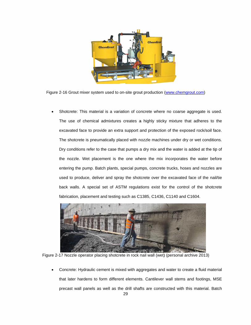
F
Fig
Figure 2-16 G
Shotcr
The u
excava
The sh
Dry co
the no
enterin
used t
back w
fabrica
gure 2-17 Noz
Concre
that la
precas
Grout mixer sy
rete: This ma
se of chemic
ated face to p
hotcrete is pn
onditions refer
ozzle. Wet p
ng the pump.
to produce, d
walls. A spe
ation, placeme
zzle operator
ete: Hydraulic
ater hardens
st wall panels
ystem used to
aterial is a va
cal admixture
provide an ex
neumatically p
r to the case
lacement is
Batch plants
deliver and sp
cial set of A
ent and testin
placing shotc
c cement is m
to form differ
s as well as 29
o on-site grou
ariation of con
es creates a
xtra support a
placed with no
that pumps a
the one whe
s, special pum
pray the shotc
ASTM regulat
ng such as C1
crete in rock n
mixed with agg
rent elements
the drill shaf
ut production (
ncrete where
a highly stick
and protection
ozzle machin
a dry mix and
ere the mix
mps, concrete
crete over th
tions exist fo
1385, C1436,
nail wall (wet)
gregates and
s. Cantilever
fts are constr
(www.chemg
e no coarse a
ky mixture th
n of the expo
nes under dry
d the water is
incorporates
e trucks, hose
e excavated
or the contro
, C1140 and C
) (personal ar
d water to cre
wall stems a
ructed with th
rout.com)
aggregate is
at adheres t
osed rock/soil
y or wet cond
added at the
the water b
es and nozzle
face of the n
ol of the sho
C1604.
rchive 2013)
eate a fluid ma
and footings,
his material.
used.
to the
l face.
itions.
e tip of
before
es are
nail/tie
otcrete
aterial
MSE
Batch

30
plants, concrete trucks, pumps, buckets and tremie tubes are used to produce, deliver
and place the concrete inside the formwork or the holes in the cantilever or drill shaft
walls respectively.
Due to the specifics of the precast panel construction, the details of it will not be analyzed
in detail as these elements are fabricated off-site and delivered to the Project. Thus, the
production rate of the panels do not impact the ones for the wall if the delivery is properly
scheduled. Cost for the panels will be considered as a fixed cost for cost calculations.
Figure 2-18 (a) Concrete placed in cantilever wall with bucket and (b) drill shaft with hopper (personal
archive 2013)
Figure 2-19 (a) Detail of tremie tube inside of rebar cage to place the concrete (avoid segregation and
soil intrusion) and (b) concrete Batch Plant (personal archive 2011 and www.gulfatlanticequipment.com)
The cement being used in the grout, concrete and shotcrete production is normally Portland
cement in compliance with ASTM C150 requirements. Aggregates production need to comply with
different regulations from the environmental perspective but as far as materials are concerned, the main

31
applicable requirements are detailed in ASTM C33. Additional regulations apply for the production such
as ASTM C94 for the production of Ready-Mix concrete (Obla and Lobo, 2006). The secondary products
used in the fabrication of the hydraulic cement mixes are also regulated by ASTM codes. A summary of
these is included below (Obla and Lobo, 2006):
ASTM C 618 Class F fly ash
ASTM C 989 Ground granulated blast
furnace slag
ASTM C 1240 Silica fume
ASTM C 260 Air entraining admixture
ASTM C 494 Water reducing admixture
2.2.2.5 Backfilling operations
Rock/Soil Nails, tie back and drill shaft walls are based on a “downward cut” configuration, where
the material in front of the wall is excavated before (nails and tie backs) or after its execution (drill shaft).
The material in the back of the wall is the existing soil/rock that remains retained by the wall.
On the other hand, cast in place cantilever and MSE Walls follow a “upward fill configuration”
where the wall is backfilled with borrowed material to complete the wall section. In the case of the MSE
walls this is even more critical as the ability of the wall to resist the loads is dependent on the friction
existing between the reinforcement ties and the granular backfill. The main difference between the cast in
place and the MSE Walls is the fact that the latter is continuously backfilled once each row of panels and
reinforcement strips are placed. Cast in place are entirely built and then backfilled once the concrete has
attained sufficient compressive strength and the drainage measures are in place.
Although general regulations exist at both the national, state and local levels, the requirements for
the materials used for the backfill are highly dependent on the particular location of the wall being
constructed. A summary of the different constraints and the consequential requirements is included below
(FHWA, 2009):
Table 2.6. Summary of Constraints and Resulting requirements for backfill
CONSTRAINT RESULTING REQUIREMENT
Flooded area Gravelly granular material
Insufficient space for straps (MSE) Increased friction angle and unit weight
Soft foundation Reduced unit weight
Need for drainage Limited passing #200 sieve
Use of metallic reinforcement Controlled PH and resistivity

A
satisfied b
paramete
production
Specificat
met in ord
S
waterproo
is washed
backfill.
Figure
As shown abo
by most non-c
rs that need
n, therefore in
tions would b
der to use a c
Figure 2-
pecific draina
of joints, weep
d from the ru
2-21 (a) Join
Earth Compa
ove, although
cohesive soils
d to be met.
ncreasing the
be the TxDOT
ertain backfill
20 Backfilling
age measures
p holes and s
unoff events
t materials an
any. Large Pa
the general
s and crushed
These may
e overall wall u
T Item 423 w
l in an MSE w
g operation in
s are to be im
shear keys ar
and that no
nd (b) detail o
anel Construct
32
requirements
d aggregates
increase th
unit cost and
where a specif
wall (TxDOT, 2
MSE Wall. (p
mplemented i
re normally us
undesired w
of weep-hole d
tion Manual a
s specified in
s, design cons
e cost and
reducing the
fic gradation,
2004).
personal pictu
n the walls. F
sed in these w
water pressur
device to inst
and FHWA M
the contract
strains can de
complication
e production ra
, PH, and res
ures archive 2
Filter fabrics,
walls to ensu
re will build
tall in MSE W
SE Wall D&C
Specification
etermine add
of the aggr
ate. An exam
sistivity need
2013)
bituminous p
ure that no ma
up in the ret
Walls (Reinforc
C Manual)
ns are
itional
regate
mple of
to be
paints,
aterial
tained
ced

33
The equipment used to perform this operations is commonly available in almost project. Loaders,
hydraulic backhoes, dump trucks, dozers and compactors are used to perform these operations. The
compaction of the area closer to the panels need to be carefully executed using tamping plates or smaller
compactors to avoid excessive loads that may induce a “lean forward” in the recently placed wall.
2.2.2.6 Stressing operations
Tie back walls include an additional step for the stressing of the reinforcement steel both for
threaded bars and cables. Once the bars or cables are placed and the hole is grouted, a certain amount
of time is required to allow the grout cure and achieve the design required compressive strength. Once an
independent laboratory has confirmed this sufficient strength, the tie backs can be pulled to the design
specified strength (Strom and Ebeling, 2001).
Soil/Rock nails are also stressed during the proof and performance testing that is performed in a
certain percentage to evaluate the actual parameters and to identify any potential deviation from the
design expected performance. This stressing does not contribute to the structural behavior of the wall as
these nails are de-tensioned after the test is completed (FHWA, 2003).
Figure 2-22 Stressing operation for (a) threaded bar tie back wall and (b) low relaxation steel strands
(personal archive 2012)
The bars or cables are stressed using hydraulic jacks that are previously calibrated to obtain the
relationship between the pressure in the jack gauge and the force exerted in the tie back (see figure
2.36). The values of the elongations on the tie backs are recorded and compared with the expected
values in order to evaluate the actual performance of the soil-grout bonding and the real resistance of the
tie back wall to resist the acting loads. Cell pressures and creep monitoring devices are also installed in
certain structures where the elements being retained are critical assets (gas lines, hospitals, dams…).

34
Highly specialized equipment and personnel are involved during stressing operations. These not
only provide the tie backs of their required load but also verify that the assumed geotechnical
performance is indeed achieved. This phase is of critical importance in both soil/rock nails and anchored
walls and as such, the costs and durations associated need to be considered when developing unit cost
and production rates. The subcontractors specialized in geotechnical solutions such as nail or anchor
walls generally own the necessary equipment to perform the stressing and testing operations so they
include these as part of their unit rates.
2.2.3 Retaining Wall Construction Cost and Production Rates
The phases, materials and equipment involved in the construction of the 5 types of retaining walls
were researched and the results were presented in Section 2.2.2. Similarly, in order to develop an
accurate set of unit costs and production rates, it is necessary to investigate the available experiences
and literature.
An accurate forecast of the construction durations and costs result of key importance when
planning, bidding, managing and controlling the construction projects (Mubarak, 2010). Although the
scheduling and estimating knowledge and tools have evolved greatly in the last decades, avoidable social
costs, delays and budget overruns are not uncommon in current highway construction (Chong, 2005).
Production rates and unit cost estimation cannot be considered an exact science. Although
certain databases are commercially available in the market, most agencies and companies rely in their
own historical data as well as proprietary programs. For example, TxDOT obtains most of the information
during the contracting and design stages from their expert senior staff, subcontractor input, RS Means
database and the Contract Time Determination System (Chong, 2005 and Hancher, et al. 1992). It is
important to note that although RS Means was developed as a unit cost database, it is being used by
several schedulers to determine the production rates for the construction activities during the planning
and design stages (Chong, 2005). It is during the application of the site specific factors that make these
unit rates and prices accurate where the expertise of the engineer is put to the test
The consequences of an improper estimation of project costs and durations can have not only
economic implications but also social, political, security or even legal repercussions (Pratt, 2011). Let us

35
picture a critical example; there are dozens of companies building the infrastructures required for the
XXXI Olympic Games in Rio de Janeiro, Brazil. Should these works incur in project delays, Brazil will not
only face multimillion dollar revenue losses but also liquidated damages from the Olympic Committee,
heavy pressure from the international community, loss of a platform for projection as an economical
power, great image damage as well as potential financial impact due to investor’s loss of confidence.
Although there is what appears to be an industry-wide effort towards developing a more reliable
set of production rates, unit costs remain carefully kept within the boundaries of each company (Chong,
2005). In reality, the commercial interests preclude these improvements to occur. A superior record-
keeping system can determine a success in future bidding processes where competing companies
propose to (Mubarak, 2010). Current duration estimation and unit costs development processes are
based on “expert guesses” and adaptation of general rates by the application of job specific factors.
The unit costs and production rates associated to the construction of any retaining wall is very
complex in nature. Not only do these rates involve several different materials but also equipment, labor,
subcontractors and overhead (Pratt, 2012). Under some circumstances, two equally adequate walls for a
certain location will be ranked just by the comparison of their unit costs and production rates (TDOT,
2012). Therefore, the author’s focus is to develop unit costs and production rates that can be used to
evaluate “competing” wall types but also to serve as a database for future preliminary studies. The next
sections present an analysis of those factors that can have the biggest impact on these values and
literature references for unit costs and production rates.
2.2.3.1 Retaining Wall Construction Cost
Pricing a certain retaining wall would not only include the construction of it but also the design,
maintenance, rehabilitation and replacement costs. This would be the life cycle cost of the retaining wall
(Penn and Parker, 2012). This analysis would result outside of the scope of this thesis defined in Section
1.1.1 where only construction costs are compared.
The literature available in regards to unit costs of retaining wall construction is limited and of
questionable applicability to real world needs. This is due to the commercial interests of the construction
companies to not to disclose their unit prices for future bidding. Additionally, previous studies used
methodologies that could have taken a better suited approach in the author’s opinion. For example,

despite th
unit of me
are not p
cost. This
ranges, th
these rang
retaining
certain m
increase.
place can
its cost fo
Figu
T
required t
the cost in
N
cost (Pou
of safety u
he concise wo
easurement n
roperly comp
s approach d
herefore not
ges. The influ
wall types fo
aterials requ
Petaja (1999
tilever walls.
r the extreme
re 2-23 Steel
he data show
to place the m
ncrease for he
Not only the c
barba, 2012)
used during d
ork performed
neglects the h
pared. Petaja
does not con
allowing a p
uence of the w
or a certain n
ired to const
9) analyzed th
Although the
e heights, both
, formwork an
wn above ne
materials whe
eights over 20
considerations
. For example
design on the
d by Petaja (1
height of the w
(1999) distr
nsider the hig
proper compa
wall height is
eed. Particul
ruct a certain
he changes o
cost of steel
h at the high a
nd concrete la
eglects the in
en height incr
0 ft. in all thre
s of the wall
e, as shown i
unit cost of a
36
1999), the res
wall as well as
ibuted the wa
gher applicab
arison when h
deep and of
arly, the cost
n wall are inc
of steel, conc
was deemed
and low level
abor cost per
crease of co
reases. This w
ee categories
location or m
in the graph b
a certain wall.
sults are rank
s equals the
alls by categ
bility of certa
heights requi
critical impor
t of the differ
creased expo
crete and form
d constant, fo
s.
CY Vs. Wall
ost in both sp
would have d
considered.
materials hav
below, there i
. Additional co
ked by cost p
different type
gories and ra
ain types und
ired span ov
rtance when c
rent processe
onentially wh
mwork cost f
rmwork and c
Height (from
pecialized lab
definitely incre
ve an influenc
is a deep influ
ost affections
per linear feet
es so the unit
nked them b
der some of
ver two or mo
comparing dif
es, equipmen
en the wall h
for different c
concrete incre
Petaja, 1999
bor and equip
eased the slo
ce on the wa
uence of the
s can be caus
t. This
costs
by unit
these
ore of
fferent
nt and
height
cast in
eased
)
pment
ope of
all unit
factor
sed by

constructi
performed
Figure 2-
T
retaining w
B
or previou
present T
constructi
This data
results of
analyzed
2.2.3.2 R
P
A more fo
output div
O
accurately
1981 and
definite a
Cost (€/m
on permits, p
d by Poubarb
-24 Influence
he results of
walls are inclu
ased on the
us references
Thesis where
ng hundreds
collection is
f this data co
and later use
Retaining Wa
roductivity co
ormal definiti
vided by input
One of the firs
y estimate co
1995 (NCHR
nd concluded
1050
m)UNI
procurement,
a et al (2012)
of design slid
f the differen
uded in Table
literature rev
s for retainin
these rates w
of square fo
s based on s
ollection cam
ed as a compa
all Constructio
ould be inform
on would be
t”.
st coordinate
onstruction du
RP, 1981; He
d that “realis
1090
T COST AG
market fluctu
) by use of an
ding Safety F
nt unit costs
e 2.14, under
iew performe
g wall unit c
will be obtain
ootage of the
urveys, interv
mpaign are in
arison parame
on Production
mally defined a
e the general
d efforts perf
uration time w
erbsman et al
stic production
11
Factor of Sa
GAINST FA
37
uations or raw
n imperialist m
actor in Cant
identified in
Section 2.2.6
ed, there is a
costs. Therefo
ed first hand
e retaining wa
views and fie
ncluded in Se
eter among th
Rates
as “how much
one adopted
formed to inv
was undertake
. 1995). The
n rates are t
50
afety against s
ACTOR OFWALL
w materials co
model are incl
ilever wall un
literature ref
6.
profound lac
ore, a differe
from the per
alls types bei
eld observatio
ection 3. The
he different ty
h work can I
d by Thomas
vestigate and
en by the Tra
results for th
the key in de
1160
sliding
F SAFETY ILS
ost. The findin
uded below:
it costs (from
ferences for
ck of applicab
ent approach
rsonnel curre
ing analyzed
ons. The me
e developed
ypes of wall.
do with these
s and Krame
d develop too
ansportation R
he Herbsman
etermining re
1180
IN CIP CAN
ngs of the an
m Poubarba, 2
the main typ
ble reliable so
is adopted
ently designin
in the DFW
thodology an
unit rates w
e many resou
er (1988): “ra
ols and syste
Research Bo
(1995) were
easonable co
120NTILEVER
nalysis
2012)
pes of
ources
in the
g and
area.
nd the
will be
urces”.
atio of
ms to
ard in
more
ontract
00R

times”. Ha
engineers
past expe
D
experienc
from bein
production
Later wor
were no lo
rather foc
that desp
factors su
S
wall. Base
U
La
V
D
W
ancher et al.
s to support th
eriences. The
Figure 2-2
Despite the h
ces of the staf
ng error-free,
n drivers are
rk such as th
onger based
used in the d
ite promising
uch as weathe
everal factors
ed on the clas
Uniqueness of
abor
Varied Locatio
Dependence o
Weather and S
44
SO
(1992) perfo
he general be
results of the
25 Sources of
igh percentag
ff involved is
irrespectively
e essential to
he one develo
on uncontroll
evelopment o
correlation, r
er or workforc
s can have a
ssification dev
f Projects
ns.
on the Econom
Seasonality
4%
OURCES OF
ormed a seri
elief that in mo
eir work are sh
f Information
ge and comm
risky in natur
y of the subje
be consider
oped by Cho
ed historical r
of production
research was
ce (Chong, 20
an impact on
veloped by M
my
2
F INFORMA
38
es of survey
ost cases, the
hown below:
for Wall selec
mon use, ob
re. These par
ect’s experien
red in order
ong (2005) sh
records mixed
drivers and u
s still necessa
005).
the productio
urawski (200
21%
5
30%
ATION FOR
ys to further c
e input for ret
ction (from Ha
btaining the p
rameters are
nce. Site spe
to accurately
hifted towards
d with subjec
unreliable res
ary to develo
on rates of th
1), these fact
Risk of W
Disruption
Traffic an
Advancem
Effect of l
5%
R WALL SE
collect eviden
taining wall se
ancher et al.
production ra
subjective, n
ecific conditio
y forecast the
s specific pro
ctive experien
ource remova
op the knowle
he constructio
tors are categ
Worker Accide
ns and mater
nd accessibilit
ment in techn
learning curv
ELECTION
Past Histo
Othe
StandRate
Prev
nce among e
election came
1992)
ates from just
non-verified a
ons, as well a
e actual dura
oduction rate
ces. Chong (
al. Results sh
edge databas
on of each ty
gorized by:
ents
rial supply
ty
nology
es
Projects andorical Records
er
dard Productios
ious Experienc
expert
e from
t past
nd far
as the
ations.
s that
2005)
howed
e and
ype of
on
ce

39
Based on the literature review performed, most references concur regarding the
difficulties to accurately forecast production rates for a certain construction work (Chong, 2005;
Murawski, 2001). Independently from the records of past activity, the analysis can only be
performed under a probabilistic approach where best case and worst case are analyzed to
determine the most probable outcome for a certain set of constraints (Murawski, 2001).
As described for the unit costs, and due to the lack of applicable reliable sources or
previous references, these rates will be obtained first hand from the personnel currently
designing and constructing hundreds of square footage of the retaining walls types being
analyzed in the DFW area. This data collection will be performed by surveys, interviews and
field observations where the results are included in Sections 3.2, 3.3, 3.4 and 3.5. These
production rates will be analyzed and later used as a comparison parameter among the different
types of walls.
2.2.4 Retaining Wall Selection Process
The complicated process of determining the optimum wall type for a certain location
involves the analysis of different needs in terms of safety, economics, constructability, schedule,
material or equipment availability, procurement and pollution prevention (Yang, 2004).
After an extensive research in regards to the currently available decision models for
retaining wall selection, very few references have been located, where most of them used
Expert Systems (ES). Expert Systems are currently one of the most successful, practical, and
recognizable subsets of classical Artificial Intelligence. The ability to supply decisions or
decision-making support in a specific domain has seen a vast application of expert systems in
various fields such as healthcare, military, business, accounting, production, and human
resources (Giarratano, 2004).
Some construction problems cannot be represented nor resolved with the use of
conventional scientific algorithms, thus the need of different systems and approaches arise
(Yang, 2004). Experience-oriented problems represent a suitable alternative where solutions

40
are obtained by previous experience solutions. Due to the variety of agents and participants in
the design and construction process, the structure that surrounds the wall construction
processes is undefined and unorganized in nature. As defined by Yang (2004) “previous cases
involving construction engineering and management also play important roles in solving
problems since they show how decisions are made”. Using experienced knowledge from
domain experts and previous examples of successful decisions, can lead to acceptable
solutions. Thus, experience-oriented results as a powerful tool to imitate previous known
decision cases where the solution converged to a successful outcome (Yang, 2004).
2.2.4.1 Retaining Wall Selection Models
Initially, Lee (1989) developed a dissertation regarding the use of expert systems to
select and design retaining walls (1989). This knowledge based expert system (KBES) was
based on a OPS5 programming language that returned the most appropriate type of wall and its
main parameters based on the input data. Lee (1989) presents a model where nine types of
walls are compared by using computer programmed logic. For the particular case of temporary
retaining walls, Ikoma (1992) also used an expert system but supplemented it with fuzzy set
theory for improved solution convergence.
Further research and development led to more refined models that were based not only
in expert systems but logic regression analysis (Choi, 2010). These were the rule induction
knowledge systems (Yang, 2003) and case-based reasoning (Yau et al. 2002). Most of these
studies were based on a limited source of information such as Wuhan City (Yang, 2003) or
Taiwan (Yau et al. 2002).
An additional factor was presented by Hess and Adams (1995) which indicated that the
majority of the engineers tend to restrict themselves to select retaining wall types that they have
experience with.

input
exca
thoro
and d
F
Figure 2-2
Yau et al
t parameters,
vations in T
ough and use
dedicates exc
If Ground A A If Ground A If Ground A A If Ground A A A
Figure 2-27 Y
26 Retaining W
(2002) develo
, their softwa
Taiwan. Altho
eful for our go
cessive effort
dwater < 0.55And Soil_TypAnd Excavati
Then Rdwater < 0.55
And Soil_TypThen R
dwater >= 0.5And Soil_StruAnd Soil_Stru
Then Rdwater >= 0.5
And Soil_TypAnd Soil_StruAnd Goundwa
Then RThen R
Yau’s (2002) a
Wall Selection
oped a mode
are was able
ough the res
oals, the sco
in temporary
50 pe is Sandy_Gon_Depth >=Retaining_W50 pe is Rock Retaining_W550 ucture_Soliducture_V_SoRetaining_W550
pe is Sandy_Gucture_V_Soater <1.625 Retaining_WRetaining_W
algorithm for w
41
n System (RW
l based on ind
to return the
search, metho
ope is restrict
y structures.
Gravel = 6.500
Wall_System
Wall_System
d is Yes oft is Yes Wall_System
Gravel oft is No
Wall_System Wall_System
wall selection
WSS) develop
duction rules
e most appro
odology and
ted to Taiwan
is Auger_Bo
is Auger_Bo
is Auger_Bo
is Auger_Bois Auger_Bo
for deep exc
ped by Yang (
(RI) that dep
opriate wall t
d algorithm r
n’s downward
oring_Pile
oring_Pile
oring_Pile
oring_Pile oring_Pile
cavations in T
(2004)
pending on the
type for deep
reasoning are
d construction
aiwan.
e
p
e
n

42
With the goal of implementing the engineer’s experience into a model available to the
rest of the profession, Adams et al (1993) used a knowledge based system where by
considering four categories, i.e. functional, spatial, behavioral and economical; they were able
to discard the non-viable options before selecting the most appropriate ones. Further
developments with the use of neural network techniques to reduce uncertainties due to the site
conditions returned selection accuracies up to 72% (Sheu, 1996) but the complications of the
programming language and algorithm made these models unsuitable for the general use.
The work by Yau (1998) presents a case-based retaining wall selection system
(CASTLES) in which the case base consists of 254 previous retaining wall cases in Taiwan.
According to the ability of the user's input to accurately describe the characteristics of a new
project and a predefined similarity function, CASTLES identifies a set of feasible retaining-wall
systems from the case base. Comparing CASTLES with four actual field cases revealed that the
case-based reasoning approach is highly promising for selecting retaining wall systems.
Choi (2010) developed a different method based on machine learning techniques. This
approach requires thousands of cases to derive a reliable conclusion, but such a large number
of excavation cases are very difficult to acquire in the construction domain. There have been
efforts to develop retaining wall selection systems using machine learning techniques but based
only on a couple of hundred cases of excavation work. The resultant rules were inconsistent
and unreliable based on his findings. This paper proposed an improved decision tree for
selecting retaining wall systems. The retaining wall systems were divided into three components
(wall, lateral support, and optional grouting). A series of logistic regression analyses, analysis of
variance (ANOVA), and chi-square tests were used to derive the variables and a decision tree
for selecting retaining wall systems. The prediction accuracy rates for the retaining walls, lateral
supports, and grouting were 82.6%, 80.4%, and 76.9%, respectively, higher than the prediction
accuracy rate (58.7%) of the decision tree built by an automated machine learning algorithm.
Several computer based decision models are currently available, and the increased use
of databases will allow investigation in this field. Yang (2002) developed a rule-based

43
knowledge system (RBKS) to support knowledge acquisition. While knowledge acquisition is the
main constraint in constructing a rule-based knowledge system (RBKS), rule induction (RI) is
one of the fastest means of extracting rule-based knowledge from previous cases. Yang (2002)
developed a model that integrates a RI approach, a RBKS, and a database management
system to support the aforementioned automated knowledge action. A typical experience-
oriented problem in construction domain, selecting a suitable retaining wall system in
construction planning stage, was employed to demonstrate how to implement the model.
One year later, Yang (2003) developed a rule-based expert system for selection of both
retaining wall types and groundwater control methods in deep excavations in Wuhan city. For
this expert system, a new type of generation rule was developed in which one condition is able
to be defined with a “third state” that not only contributes directly to reaching the conclusion in a
rule, but also factors into calculating the reliability of the conclusion. The traditional backward
chaining technique was improved to accommodate the change of a rule type and a fuzzy
backward chaining method was established to increase reasoning flexibility. Using backward
chaining as a fundamental element was found to be convenient to form a complicated reasoning
network in the inference engine. Finally, two knowledge bases were built from more than 100
case histories and other resources, and the new expert system proved to be effective in case
studies.
2.2.4.2 State Guidelines for retaining wall selection
Independently from the academic research, the Departments of Transportation of some
States have attempted to provide a set of guidelines to perform this selection process by
developing manuals. For example, Tennessee Department of Transportation issued its
Transportation Earth Structures Manual which included a list of parameters that determine
which wall of nine available types is the most adequate. The decision to select a particular
retaining wall system for a specific project requires a determination of both technical feasibility
and comparative economy (TDOT 2012). These factors were summarized as:
44
Cut or fill earthwork situation
Size of wall area
Average wall height
Foundation conditions
Availability and cost of select
backfill material
Cost and availability of ROW
Complicated horizontal and vertical
alignment changes
Need for temporary excavation
support systems
Maintenance of traffic during
construction
Aesthetics
None of the models previously described accounted for the economic implications of
each type of wall as a differentiating parameter when selecting the most appropriate wall. This
cannot only jeopardize the overall cost of the resulting wall but also put the entire decision
model in question for practical applications.
2.2.4.3 Optimization and parametric design
There are several references available in scientific publication in regards to methods of
optimization and parametric design of a particular type of walls. These models and methods
focus on the improvement mechanisms but require that the wall type is predetermined. For
example, the work developed by Yepes, Alcala and Perea (2002), focused on the economic
optimization of reinforced concrete earth-retaining walls used in road construction by use of
simulated annealing algorithm. The formulation of the problem included 20 design variables:
four geometrical; four material types; and 12 variables for the reinforcement set-up. The study
estimated the relative importance of factors such as the base friction coefficient, the wall-fill
friction angle and the limitation of deflections. Finally, the paper presented a parametric study
of commonly used walls from 4 to 10 m in height for different fills and bearing conditions
returning total costs, pre-dimensioning parameters and rebar consumptions.
In the case of temporary retaining walls, the Metropolitan Expressway Public
Cooperation in Japan bases the selection process in the flowchart shown below:

45
Figure 2-28 Temporary Wall selection process for Metropolitan Expressway Public Cooperation
Although developed for optimum cost design of cantilever cast in place walls, the
approach adopted by Poubarba et al. (2012) will be used as a reference for the retaining wall
selection model (RWSM) developed in this research. This Chaotic Imperialist Competitive
Algorithm considers a system “where the imperialistic competition begins in which any empire
(wall type) that is not able to succeed in this competition and cannot increase its power (or at
least prevent losing its power) will be eliminated from the competition (selection process). It
means that weak empires will lose their power and ultimately will collapse” (Poubarba, 2012).
Each wall type will be “facing” all the “adversary” wall types, in such a manner that the last
remaining type will be the most adequate among the competing ones (i.e. potential wall types).
2.2.5 Analysis of 4 known walls
In order to determine which parameters are instrumental for each type of wall, the
literature research performed in section 2.2.1 and 2.2.2 is supplemented with an analysis of 4
known walls of a current heavy civil construction Project being constructed in the DFW area.

and
matc
facto
2.2
prese
A key
the p
TxDO
due
remo
remo
they
was
These fou
validated. Th
ches the real
ors affecting th
.5.1 Wall 1
Wall 1 co
ents a variabl
yway is adde
passive earth
OT Class C 3
During the
to the organ
oved and repl
oved in the ar
swell and ex
placed in 8” c
Fig
ur walls will a
he identified i
ity. Both ma
he model dur
onsists on a
le height from
d to the footin
pressure of t
600 psi with a
e geotechnica
nic content, d
laced with en
ea of wall fou
xpand which c
compacted lift
gure 2-29 Typ
lso be used a
nput parame
atching and d
ing the select
cantilever w
m 5 to15’ with
ng to increase
he foundation
a steel reinfor
al exploration
deleterious an
gineering fill.
undation. Whe
can affect the
ts at least to 9
pical sections
46
as a reference
eters will be u
differing resp
tion process l
wall construct
a stem thickn
e the lateral r
n soil. The co
rcement of AS
, deposits of
nd anthropic
Additionally,
en stiff clays e
e stability of t
98% of the re
and wall prop
e when the d
used to chec
onses are ev
ed to each pa
ed with reinf
ness of 1’ whe
resistance of t
oncrete type c
STM A615 Gr
human activi
materials, a
seams of sti
experience an
the wall (Jalla
eference Proc
perties for Wa
ecision mode
ck if the retur
valuated to i
articular outpu
forced concre
ere the footin
the structure,
considered in
rade 60.
ties were enc
ll this underl
iff clay were r
n increase in
a, 1999). Thi
ctor (Tex-114-
all 1 (Persona
el is evaluated
rned wall type
identify which
uts.
ete. This wa
g width is 11’
by mobilizing
n the design is
countered and
ying soil was
required to be
water conten
is imported fi
-E), controlled
al archive 201
d
e
h
ll
’.
g
s
d
s
e
nt
ll
d
12)
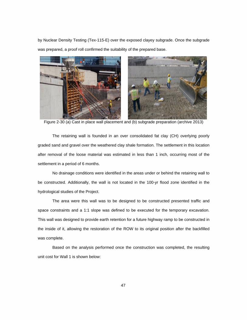
47
by Nuclear Density Testing (Tex-115-E) over the exposed clayey subgrade. Once the subgrade
was prepared, a proof roll confirmed the suitability of the prepared base.
Figure 2-30 (a) Cast in place wall placement and (b) subgrade preparation (archive 2013)
The retaining wall is founded in an over consolidated fat clay (CH) overlying poorly
graded sand and gravel over the weathered clay shale formation. The settlement in this location
after removal of the loose material was estimated in less than 1 inch, occurring most of the
settlement in a period of 6 months.
No drainage conditions were identified in the areas under or behind the retaining wall to
be constructed. Additionally, the wall is not located in the 100-yr flood zone identified in the
hydrological studies of the Project.
The area were this wall was to be designed to be constructed presented traffic and
space constraints and a 1:1 slope was defined to be executed for the temporary excavation.
This wall was designed to provide earth retention for a future highway ramp to be constructed in
the inside of it, allowing the restoration of the ROW to its original position after the backfilled
was complete.
Based on the analysis performed once the construction was completed, the resulting
unit cost for Wall 1 is shown below:

48
Table 2.7. Unit cost distribution for known Wall 1 (self-developed)
WALL 1 UNIT COST
CONCEPT COST PER ft2
Equipment $0.18
Materials $9.47
Labor/Subcontractor $47.07
$56.73
The average production rate was identified as 750 sq ft /day based on an extended time
period that spanned through 20 days of construction monitoring.
2.2.5.2 Wall 2
Wall 2 differs with Wall 1 in almost every parameter that can be considered prior to
determine the most suitable type to design for a specific location. Wall 2 is defined to allow a
direct connector from the surface to a lower highway level. This wall is a downward type
planned to retain cuts that will support tan and gray limestone. Wall 2 consists in a combination
of rock nails and fascia panels, connected with an in place concrete closure pour. The fascia
panel cover responded to an aesthetic requirement more than to a pure stability need.
Wall 2 maximum height is 32 feet, where 85% of the exposed height fell in grey
unweather limestone. At the point of maximum height, seven rows of nails, separated 4.5’ were
necessary to stabilize the rock mass against failure once the vertical cut was executed. The
good quality of the rock identified in the majority of the wall face allowed the permanent rock nail
to be designed and constructed in this area.
The unit weight, effective internal friction angle, and effective cohesion values were
generated based on results of direct shear and triaxial shear test results on weathered tan
limestone, and gray limestone.

estim
afore
Tab
Clas
Figure 2-
The pullo
mated based
ementioned m
ble 2.8. Reco
Class 1
ss 2 Tan Lime
-31 Rock Nail
ut resistances
d on uncon
materials, coup
mmended nostrengths for
1 Tan Limesto
estone and Gr
drilling and d
s of clay soils
nfined comp
pled with resu
ominal factorerock-nail wal
Material
one
ray Limestone
49
drainage oper
s, weathered
pressive stre
ults of recent
ed presumptivl design (Tab
Presu
Nomina
LRFD
Bond R
130
e 375
rations (perso
tan limestone
engths of in
pullout field t
ve pullout resible 5 for LRFD
umptive
al Factored
Dry Case
Resistance
00 psf
50 psf
onal archive 2
e and gray lim
ntact specim
tests.
istances or faD design)
Presumpt
Factored
Case
Resis
162
469
2013)
mestone were
mens of the
actored bond
ive Nominal
LRFD Wet
e Bond
stance
25 psf
90 psf
e
e

repo
the n
Geoc
strips
minim
subc
issue
beha
supe
as pe
Although
rt did not sho
need of spec
composite dra
s were contin
mum of 12 inc
The cons
contractor wh
es during co
avior is highly
ervision is req
er FHWA0-IF
Figure 2-32
Wall 2 was a
ow groundwa
cific considera
ainage panel
uous from the
ches overlap
struction of a
ich not only
nstruction tha
impacted fro
quired. Additio
F-03-017, Geo
Typical secti
also located o
ater, the drain
ations to be
s or strips w
e top to the b
to assure tha
a rock nail
has the equ
at can affect
m the actual
onally, an ext
otechnical Cir
50
ons and wall
outside the 10
nage conditio
accounted fo
ere used to p
bottom of the
at water flow is
of this char
uipment need
t the integrity
rock paramet
tensive camp
rcular No. 7 w
properties fo
00-yr flood zo
ons of the exi
or in both the
provide drain
wall and 36
s not impede
racteristics re
ded but also
y of the wal
ters and there
paign of, proo
was followed
or Wall 2
ones and the
isting soil fac
e design and
nage between
inches wide.
d.
equires of a
the knowled
ll being cons
efore, close m
of and perform
to evaluate t
e geotechnica
ce determined
construction
n nails. These
Splices had a
n specialized
ge to identify
structed. Wa
monitoring and
mance testing
the actual na
al
d
n.
e
a
d
y
ll
d
g
il

51
behavior as well as the verification of the soil parameters by performing sacrificial tests
performed in extra nails pulled to failure.
Specific considerations were required due to the permanent nature of this wall. The
long term durability and stability of this type of wall is highly dependent in the degree of success
achieved in the corrosion protection of the steel reinforcement. Rock nails were protected from
corrosion by means of fusion bonded epoxy coating and grout protection for Class 2 protection
in accordance with FHWA-IF-99-015, Geotechnical Engineering Circular No. 4.
Based on the analysis performed once the construction was completed, the resulting
unit cost for Wall 2 is shown below:
Table 2.9. Unit cost distribution for known Wall 2 (self-developed)
WALL 2 UNIT COST
CONCEPT COST PER SF
Equipment $14.50
Materials $36.22
Labor/Subcontractor $21.74
$72.46
The average production rate was identified as 625 sq ft /day based on an extended time
period that spanned through 25 days of construction monitoring.
Figure 2-33 Epoxy coated protection for soil/rock nail bars in Wall 2 (archive 2013)

52
2.2.5.3 Wall 3
Wall 3 was also a downward construction wall, but in this case located in an area of
cohesive soils, with predominance of shaley clays and weathered shale. The soil profile
consisted of clays transitioning into shaley clays overlying the Eagle Ford Shale. Both the clays
and shaley clays encountered were identified to be very expansive. The Eagle Ford Shale was
a soft dark gray to gray clay shale. The shale was highly expansive and contained soluble
sulfates, being considered as highly corrosive.
Wall 3 is a drill shaft wall, executed by a sequence of drill shafts spaced between 5 and
6.5 feet, being all of them joined by a reinforced concrete capping beam. These shafts had
diameters from 3-1/2’ to 5’ with a maximum length of 70’. The exposed height of this wall varied
between 17 and 35 feet.
Figure 2-34 Wall 3 (a) shaft and (b) capping beam reinforcement (archive 2014)
This high percentage of exposed height determined the wall to behave as a
cantilevered wall, therefore requiring some sections to be anchored by means of actively
stressed tie backs. The shale weathers rapidly when exposed thus losing both durability and
stability if left open for even short periods of time. This determined the need of a strictly
monitored effort between the earthwork and tie back subcontractors in order to minimize the
exposure of the sensitive shale layers once exposed.

Figu
spec
ident
cons
enco
Figure 2
ure 2-36 (a) W
As in the
cialized subco
tify those iss
tructed. Both
ountered, ther
2-35 Wall 3 ge
Wall 3 drill sha
case of Wall
ontractor whic
sues during
h the shafts
refore needing
eotechnical c
afts with tie ba
2, a tied bac
ch not only ha
construction
and tie back
g a monitoring
53
onfiguration f
acks and (b)
ck drill shaft w
as the equipm
n that can a
ks behavior is
g system in p
for calculation
typical sectio
wall of this ch
ment needed
affect the in
s highly impa
place during c
ns (archive 20
on (personal a
aracteristics r
but also the
tegrity of th
acted from th
construction.
013)
archive 2014)
requires of an
knowledge to
e wall being
he actual so
)
n
o
g
il

IF-03
well
pulle
relati
value
value
resis
with
Class
pre-g
prote
Addit
impo
conta
reduc
Additiona
3-017, Geotec
as the verific
d to failure.
The cable
ionship betwe
es of the elo
es in order t
tance of the t
Figure 2-3
As previo
a significant
s I protection
grouted poly
ective end c
tionally, heat
In additio
ortant factors
ained a critica
ction of the r
lly, an extens
chnical Circul
cation of the
es were stre
een the press
ongations on
to evaluate t
tie back wall t
37 (a) Wall 3 a
ously describe
sulfate conte
required with
corrugated tu
cap over nut
shrink sleeve
n to the type
in Wall 3 was
al high capaci
road traffic an
sive campaign
lar No. 7 was
soil parame
essed using
sure in the ja
the tie backs
the actual pe
to resist the a
anchor testing
ed, the shale
ent. As define
h multiple bar
ube in both th
t and washe
es at connecti
e of soil to be
s the lack of la
ity highway, b
nd no affectio
54
n of, proof an
s followed to e
ters by sacri
hydraulic jac
ck gauge and
s were recor
erformance o
acting loads.
g and (b) load
ey materials e
ed by the FH
rrier layers wit
he bond and
er and filled
ions were use
e contained w
ateral space
being therefor
on to existing
nd performan
evaluate the a
ficial tests pe
cks previously
d the force ex
rded and com
of the soil-gr
d-pressure cu
encountered
HWA Geotech
th at least two
free-stressin
with corros
ed for increas
with the retain
available for
re necessary
g infrastructur
nce testing as
actual tie bac
erformed in e
y calibrated
xerted in the
mpared with
rout bonding
urve (archive
were highly
hnical Circula
o levels of pro
ng length, ce
sion inhibiting
sed protection
ning wall, on
the construct
to execute a
re. Considerin
s per FHWA0
ck behavior as
extra anchors
to obtain the
tie back. The
the expected
and the rea
2014)
corrosive and
ar 4, minimum
otection being
ntralizers and
g compound
n.
e of the mos
tion. This Wa
wall with zero
ng the lack o
0-
s
s
e
e
d
al
d
m
g
d
d.
st
ll
o
of

spac
appe
unit c
perio
2.2
cons
artific
steel
ce, clayey so
eared to be th
Based on
cost for Wall 3
Tab
The avera
od that spanne
.5.4 Wall 4
The last o
isting in a co
cial reinforcin
with lengths
Figu
il, continuous
e only viable
n the analysis
3 is shown be
ble 2.10. Unit
Lab
age productio
ed through 30
of the walls a
ombination o
ng. In this par
between 8 an
ure 2-38 Wall
s support and
option.
s performed o
elow:
t cost distribut
WALLCONCEPTEquipmentMaterials
bor/Subcontra
on rate was id
0 days of con
analyzed, Wa
of precast co
rticular case,
nd 16 feet. Th
4 MSE Wall T
55
d downward
once the con
tion for known
L 3 UNIT COSCOS
36
actor 41
entified as 45
struction mon
all 4, is a Mec
ncrete panel
the reinforce
he maximum
Typical sectio
construction
nstruction wa
n Wall 3 (self
ST ST PER SF 38.06$ 68.51$ 45.68$ 52.25$
50 sq ft /day b
nitoring.
chanically Re
s and backfi
ement consis
wall height w
on (personal a
, tied back d
s completed,
f-developed)
based on an e
einforced Ear
ill that is con
sted in strips
was 12 feet.
archive 2012)
drill shaft wa
, the resulting
extended time
rth wall (MSE
nstructed with
of galvanized
)
ll
g
e
E)
h
d

56
The wall foundation consisted in both previous embankment fills and existing high
plasticity clays (fat clays). These materials were deemed to provide sufficient bearing capacity
but required some preparatory work by ripping, conditioning and compaction.
Figures 2.38. Backfilling operation in Wall 4. (a) strip placement over executed lift and (b) loader
places backfill over strips to avoid strip damages. (personal pictures archive 2013)
An additional requirement for this wall was the location inside the 100-yr flooded zone
due to a close creek. Specific drainage measures were specified in the design consisting in filter
fabrics, bituminous paints, waterproof joints and underdrain. These measures were constructed
to ensure that no material is washed from the runoff events and that no undesired water
pressure will build up in the retained backfill. Not all the height was subject to the potential
flooding and therefore TxDOT Item 423, Type B above inundated wall section and Type D
below the 100-year flood elevations were defined with a filter fabric to separate the two different
fill types.
No specific space constraint was identified in the proposed location for Wall 4,
therefore, the temporary slope excavated did not constitute a design constraint. Additionally, it
was required to build the wall in a short period of time which determined the adequacy of this
type over a cast in place concrete retaining wall. If the wall would have been located outside the
flooded zone, the defined type would likely still be an MSE without the Type B backfill and
drainage measures. Based on the analysis performed once the construction was completed, the
resulting unit cost for Wall 4 is shown in Table 2.11:

57
Table 2.11. Unit cost distribution for known Wall 4 (self-developed)
WALL 4 UNIT COST
CONCEPT COST PER SF
Equipment $4.49
Materials $28.80
Labor/Subcontractor $19.18
$52.47
The average production rate was identified as 1150 sq ft/day based on an extended
time period that spanned through 8 days of construction monitoring.
2.2.6 Conclusions and findings of literature research and background review
Most of the selection models being developed to date have been applied to a wide
range of decisions and fields. By introducing different parameters into the computer algorithms,
the systems can return the optimum solution for the desired reasoning logic. These models,
such as the ones proposed by Choi (2010), Yang (2003), Yau (2002) or Lee (1989) require of
extensive knowledge information being input in the systems as well as a proficient programming
capabilities in the engineer making the decision. The research performed reveals that no
software has implemented these models into a user-friendly tool that can be easily used for the
engineers in need of determining the most suitable wall for their particular project.
Although not definitive, the fact that no private company has entertained the process to
make these tools in software available to the market, casts doubt over their ability to properly
select the most appropriate wall based on a certain input. It is almost certain that if commercially
profitable, any software company would have already implemented them for profit purposes.
The methods of optimization such as the one presented by Yepes et al (2002) do not
present a usable tool for the purpose of wall selection as they focus on the optimization of a
particular structure once the type has been predetermined. This focus on the structural and
constructability implications of different parameters but do not allow the consideration of
different type of wall.
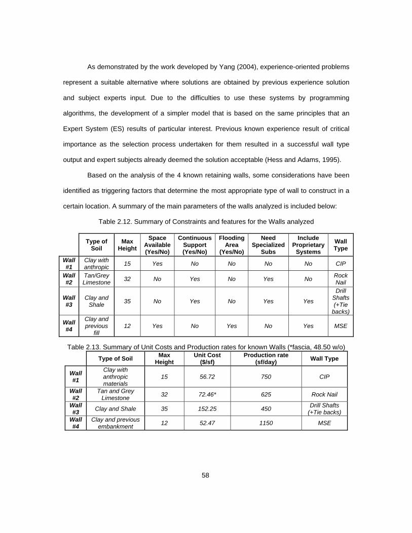
58
As demonstrated by the work developed by Yang (2004), experience-oriented problems
represent a suitable alternative where solutions are obtained by previous experience solution
and subject experts input. Due to the difficulties to use these systems by programming
algorithms, the development of a simpler model that is based on the same principles that an
Expert System (ES) results of particular interest. Previous known experience result of critical
importance as the selection process undertaken for them resulted in a successful wall type
output and expert subjects already deemed the solution acceptable (Hess and Adams, 1995).
Based on the analysis of the 4 known retaining walls, some considerations have been
identified as triggering factors that determine the most appropriate type of wall to construct in a
certain location. A summary of the main parameters of the walls analyzed is included below:
Table 2.12. Summary of Constraints and features for the Walls analyzed
Type of
Soil Max
Height
Space Available (Yes/No)
Continuous Support (Yes/No)
Flooding Area
(Yes/No)
Need Specialized
Subs
Include Proprietary
Systems
Wall Type
Wall #1
Clay with anthropic
15 Yes No No No No CIP
Wall #2
Tan/Grey Limestone
32 No Yes No Yes No Rock Nail
Wall #3
Clay and Shale
35 No Yes No Yes Yes
Drill Shafts (+Tie
backs)
Wall #4
Clay and previous
fill 12 Yes No Yes No Yes MSE
Table 2.13. Summary of Unit Costs and Production rates for known Walls (*fascia, 48.50 w/o)
Type of Soil Max
Height Unit Cost
($/sf) Production rate
(sf/day) Wall Type
Wall #1
Clay with anthropic materials
15 56.72 750 CIP
Wall #2
Tan and Grey Limestone
32 72.46* 625 Rock Nail
Wall #3
Clay and Shale 35 152.25 450 Drill Shafts
(+Tie backs) Wall #4
Clay and previous embankment
12 52.47 1150 MSE

59
The data shown in Table 2.13 evidences the aforementioned considerations in regards
to how differing parameters other than just the geometry and type of soil influence the most
suitable type of wall for a particular location.
None of the different methods identified during the extensive literature research
includes four of the most important considerations such as direction of construction, height
limitation of each type, unit cost per unit of area of wall and nominal production rate.
Disregarding these parameters severely handicaps the ability of these models to accurately
select the most appropriate wall (Adams et al., 1993).
Based on the results of the literature research, it has been deemed essential to perform
field observations, surveys and interviews to collect and gather the required data to build the
selection model and comprehensive database. Currently, no single document or publication
gathers enough information that allows the engineer in need to determine the most adequate
wall for a certain location. Only through a careful balance between calculations, experience and
several literature sources, the decision can be taken. The knowledge associated with the
educated decision of which wall type results optimum for a certain location is wide in nature,
multidisciplinary and affected by several aspects. Only by observing actual field operations,
interviewing design and construction experts and performing surveys will the necessary data be
obtained (Chong, 2005).
The literature research performed supports the need for a simple model that accounts
for production rates and costs during the decision process. Additionally, due to the absence of
previous experiences that separate upward and downward construction, this will be one of the
basis for the selection model developed in this research. Also, the absence of published rates
and costs for wall construction determines the need to perform a specific analysis via
interviews, surveys and observations to develop actual unit costs and rates to serve as the
starting point for future needs.

60
Although limited, different sources of unit costs and production rates have been
obtained such as TxDOT (2007), TDOT(2012), the known walls included in Section 2.2.5,
author’s experiences or Chong (2005). After the analysis of all these different parameters for the
walls being considered, it results obvious that a project specific analysis is critical for detailed
studies. As shown in table below, different sources present greatly different values for the unit
costs. The references for production rates publicly published are almost non-existent (Mubarak,
2010 and Pratt, 2012). Using a certain parameter under a set of constraints that does not adapt
to the actual ones, can lead to adverse consequences in terms of budget and schedule.
Table 2.14. Comparison between Unit Costs obtained from different sources
UNIT COST OF DIFFERENT TYPES OF RETAINING WALL ($/sf face of wall)
UP
WA
RD
C
ON
ST
RU
CT
ION
(F
ILL
)
Wall Type TDOT (2012)
TxDOT (2007)
SPANISH HIGH SPEED TRAIN
(2007-2009)
KNOWN WALLS (Section 2.5) (2013-2014)
Concrete Gravity Wall /25-35 85 72 N/A
Concrete Cantilever /25-60 85 75 57
CIP Counterforted /25-60 85 N/A N/A
Concrete Crib /25-35 26 N/A N/A
Gabion /25-50 26 65 N/A
MSE (precast facing) /22-35 35 58 52.5
DO
WN
WA
RD
C
ON
ST
RU
CT
ION
(C
UT
)
Sheet Pile Wall 15-40 N/A N/A N/A
Slurry (Diaphragm) /60-86 N/A 115 N/A
Tangent pile wall (drill shaft wall)
/40-75 N/A 108 N/A
Secant Pile Wall /40-75 70 121 N/A Anchored Wall /15-75 95 135 152 Soil Nailed Wall /15-56 65 95 72.5 Micropile Wall /75-125 N/A 185 N/A
Due to the high variability of unit costs and rates presented in the consulted literature
references, for the present Thesis, it is deemed necessary to develop more accurate rates and
unit costs based on field observations, analysis of project-specific constraints, surveys and
interviews to expert subjects.
All the data collected will be gathered, compared and analyzed in order to develop a
retaining wall database that can serve as a starting point for future reference during preliminary
or feasibility studies.

61
Chapter 3
Methodology
Several methods and sources have been utilized to both obtain the required information as well
as to develop and forecast the required parameters for each type of retaining wall. As
determined in Chapter 2, the sources available for the selection of the optimal retaining wall
type as well as to identify the unit costs and production rates are very limited. Thus, in order to
have accurate and useful parameters as input for our selection model, it is necessary to
supplement this background information with actual collected data. Additionally, a database will
be developed in the present research and therefore the information collected will be compiled,
compared and analyzed.
The methodology followed during the research performed for this Thesis is summarized
in the next Sections.
3.1 Definition of the research and phases of data collection
The method used during this research responded to the needs identified during the
initial conception and literature review phases. In order to determine the data required to be
used as input for our decision model, the design process followed for 4 known walls was
analyzed jointly with the Engineers responsible for them. This helped to further define which
parameters were required to be collected in order to properly develop our selection guidelines.
The results of this analysis and the main parameters that determined the type selected for each
case are included under Section 2.2.5 and summarized in Tables labeled 2.12 and 2.13.
Literature review was also identified as a critical stage for the research. Neglecting
these previous steps from previous professionals would not only be a researching negligence
but also a severe handicap for the potential developments to be achieved in this Thesis. The
findings of this literature review critically influenced the subsequent stages of research data
collection, the database and the wall selection model development.

62
The identified lack of published comprehensive guidelines for retaining wall selection
determined the need of performing a series of surveys, interviews and field observations of
retaining wall construction.
This data was then organized, summarized and analyzed in order to identify those
critical drivers for each type of retaining wall that determine the adequacy or non-adequacy for a
certain set of constraints (direction of construction, soil type, height, cost, schedule, etc.).
In general terms, the research performed consisted in six main phases listed below:
Perform a research of the existing literature regarding retaining wall construction with
emphasis on those parameters that determine the optimum type for the different
constraining parameter.
Analyze the currently available retaining wall types in heavy civil construction,
identifying their applicability, advantages and disadvantages.
Study and analyze a selection of personally known heavy civil projects to identify the
most used wall types and configurations.
Perform surveys and interviews to expert personnel involved in the different phases of
the retaining wall definition and implementation. This will include design, bidding,
construction and maintenance.
Observe and monitor the construction processes followed for the selected types of walls
with the purpose of obtaining unit costs and production rates for each of them as well as
critical parameters to be considered during the selection model development.
Summarize and analyze all data collected so it allows the development of a sequential
decision model that will serve as a selection guideline that returns the optimum wall
type with project constraints as input but also serve as a database for future reference.
The methodology followed during this research is summarized in the next page,
including the interrelations between the different phases. It is re-emphasized that the results of
each phase were used as input for the subsequent steps of the research.
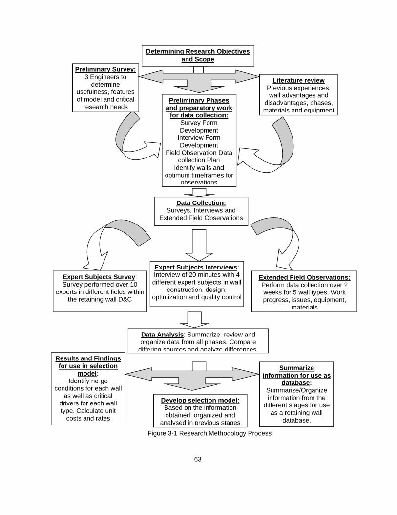
ExpSurv
expertsthe
Resultfor us
Ideconditio
as wdrivertype.
cos
Preliminary 3 Enginee
determusefulness, fof model and
research n
pert Subjectsvey performeds in different fe retaining wa
ts and Findinse in selectio
model: entify no-go ons for each wwell as criticars for each wa Calculate unsts and rates
D
Survey: ers to ine features d critical needs
s Survey: d over 10 fields within all D&C
Daorg
diffengs on
wall l all nit
F
Prelimand pr
for daSuDe
InteDe
Field Ocol
Idenoptimum
ob
Determining an
DatSurvey
Extended
Expert SubInterview ofdifferent exp
construoptimization
ata Analysis: ganize data frering sources
DevelopBased oobtaine
analysed
Figure 3-1 Re
63
minary Phaseeparatory woata collectionurvey Form evelopment erview Form evelopment
Observation Dllection Plan
ntify walls andm timeframesbservations
Research Obnd Scope
ta Collectionys, Interviewsd Field Observ
bjects Intervf 20 minutes wpert subjects uction, designn and quality c
Summarize, om all phasesand analyze
p selection mon the informaed, organized in previous s
esearch Meth
es ork n:
Data
d s for
bjectives
n: and vations
views: with 4 in wall
n, control
E
review and s. Compare differences
model: ation and
stages
hodology Proc
LiteraturPrevious ewall advan
disadvantagmaterials an
Extended FiePerform dataweeks for 5 progress, iss
ma
Summinformation
databSummarizeinformation
different staas a retai
datab
cess
re review experiences, ntages and ges, phases, nd equipment
eld Observata collection ovwall types. W
sues, equipmaterials
marize n for use as base: e/Organize n from the
ages for use ning wall
base.
t
tions: ver 2
Work ment,

64
3.2 Background and literature review
It is essential for any research to locate, analyze and use the previous references as a
base for the future work as well as to support the need for the topic being under consideration.
Not only the previous work can be used as the starting point but also can serve to identify those
areas in need of additional research, study and developments.
Previous experiences on the academic and professional field were analyzed as well as
those previous models developed for selecting the optimum retaining wall type for a certain
location or need. These models were complicated in nature and computational in form,
therefore requiring an extensive knowledge in programming in order to use them in a real-world
application. This determined the need of developing a simpler model that can be quickly used
by engineers in need during preliminary or feasibility phases.
During the definition of the construction phases, materials and equipment involved
during the construction of the retaining walls, specific technical references from journals,
articles, records and books were consulted. Additional input was obtained from the expert
personnel interviewed as well as the field observations detailed in Section 2.2.2.
All construction research is highly dependent on previous experiences as well as an
accurate record keeping process. The privileged position that the author finds himself allowed
an extensive analysis of data from previous projects as well as data collection from on-going
wall construction in the DFW area. The data collected included unit costs, production rates,
construction issues and decisions taken for existing walls by design engineers.
3.3 Surveys and Interviews to expert subjects
The literature research evidenced a lack of published data in regards to expert decision
models for retaining wall construction as well as unit costs and production rates. Additionally,
the models available in the literature neglected critical data such as direction of construction,
cost or schedule. Thus, it was determined that the expertise from experienced engineers was
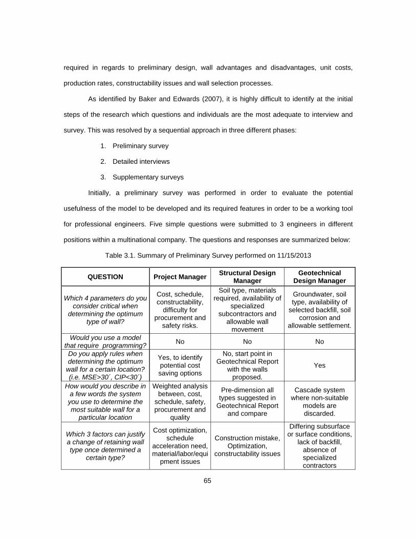
65
required in regards to preliminary design, wall advantages and disadvantages, unit costs,
production rates, constructability issues and wall selection processes.
As identified by Baker and Edwards (2007), it is highly difficult to identify at the initial
steps of the research which questions and individuals are the most adequate to interview and
survey. This was resolved by a sequential approach in three different phases:
1. Preliminary survey
2. Detailed interviews
3. Supplementary surveys
Initially, a preliminary survey was performed in order to evaluate the potential
usefulness of the model to be developed and its required features in order to be a working tool
for professional engineers. Five simple questions were submitted to 3 engineers in different
positions within a multinational company. The questions and responses are summarized below:
Table 3.1. Summary of Preliminary Survey performed on 11/15/2013
QUESTION Project Manager Structural Design
Manager Geotechnical
Design Manager
Which 4 parameters do you consider critical when
determining the optimum type of wall?
Cost, schedule, constructability,
difficulty for procurement and
safety risks.
Soil type, materials required, availability of
specialized subcontractors and
allowable wall movement
Groundwater, soil type, availability of
selected backfill, soil corrosion and
allowable settlement.
Would you use a model that require programming?
No No No
Do you apply rules when determining the optimum
wall for a certain location? (i.e. MSE>30´, CIP<30´)
Yes, to identify potential cost saving options
No, start point in Geotechnical Report
with the walls proposed.
Yes
How would you describe in a few words the system you use to determine the most suitable wall for a
particular location
Weighted analysis between, cost,
schedule, safety, procurement and
quality
Pre-dimension all types suggested in
Geotechnical Report and compare
Cascade system where non-suitable
models are discarded.
Which 3 factors can justify a change of retaining wall type once determined a
certain type?
Cost optimization, schedule
acceleration need, material/labor/equi
pment issues
Construction mistake, Optimization,
constructability issues
Differing subsurface or surface conditions,
lack of backfill, absence of specialized contractors

66
The results of this simple and quick survey were instrumental in order to not only
identify the need for a decision model simpler than the ones developed to date but also to
determine that additional data was needed as input for the selection process to supplement
geometrical and geotechnical constraints.
The consulted engineers concluded that the proposed model should not include any
platform that required language programming from them. Additionally, the responses from these
expert colleagues resulted in a series of critical factors to account for when determining the
optimal wall type:
Table 3.2. Driving factors identified by the three consulted experts
CONSTRUCTION RELATED
GEOTECHNICALLY RELATED
STRUCTURALLY RELATED
OTHERS
Cost Optimization Allowable Settlement Allowable Settlement Safety risk reductionSchedule
compression Soil Type Constructability issues
Environmental Compliance
Procurement issues (material, equipment)
Groundwater Designer expertise for specialized wall types
Quality of product
Availability of selected backfill
Soil corrosion
Lack of specialized subcontractors for
certain walls
Availability of selected backfill
The consulted geotechnical engineer suggested a “cascade model” that resembled in
its concept to the Chaotic Imperialistic Algorithm developed by Poubarba et al. (2012) where
only the “victorious empire” (i.e. wall type) remains after being face with all the “opponents” (i.e.
the other potential types). The fusion of these two concepts as well as the introduction of
production cost and rates resulted in the baseline for the selection model developed in this
research as detailed in Section 4.2 and Appendix D.
In order to collect accurate data that could be compared and processed for use in the
model, predetermined survey and interview forms were developed. This forms facilitated the
interview and survey processes, not only reducing the time required to complete them but also
drives the responses to those parameters most needed for the decision model. Only by analysis

67
of comparable data it is possible to identify driving factors as well as trends, disagreements
and/or concurrences among the different professionals.
Interviews and surveys can be satisfactorily combined for research needs (Driscoll,
2011). Interviews are a more comprehensive tool that not only incorporate the subject’s
responses but also subjective expert considerations and experience examples of great
importance. It was determined after the interview process that due to the design related
background of the interviewed experts, cost and production information was still in need. This
determined the selection of the recipients of the survey. These experts were mainly managers,
construction related personnel and geotechnical subcontractors.
3.3.1 Survey to Eight Expert professionals.
As described in the previous section 3.3, once the interviews were completed, a lack of
cost and production data was identified. These parameters are mainly numerical and did not
require an great level of detail other than the constraints that affects them. Therefore, the most
suitable tool to collect them was determined to be a series of surveys (Kelley et al. 2003).
Eight retaining wall construction and management experts were selected to participate
in the survey. Two of the initially selected individuals declined to participate and were replaced
with two geotechnical engineers from an specialized company.
The recipients of this survey chose to remain unidentified due to the commercial
implications of production rates and unit costs. These values were provided as typical, and
would not be applicable to every case in general. Only by a detailed analysis where all site
specific constraints are analyzed can return accurate cost/production rates (Mubarak, 2010).
The given values do not necessarily belong to the known walls presented on Section
2.2.5 or the field observed ones. An effort to preserve the proprietary nature of the information
provided by the participants in the survey was undertaken during the entire research.

68
A predetermined survey form was developed and provided to all the participants,
requesting them to be returned within a week. All participants completed it before the allowed
timeframe. The survey form distributed is included in Table 3.3.
Table 3.3. Sample Retaining Wall Selection Survey Form Name: Years of experience: Position: Date: Area of expertise: Country where most experience: Please list the 3 main factors you consider when developing unit costs for retaining walls
in general terms:
Please list the 3 main factors you consider when developing production rates for retaining walls in general terms:
Please list the 3 main factors to consider when developing unit costs and production rates for retaining walls for the following types:
o Cast in place = o Sheet pile wall = o Drill Shaft wall (w/o tie backs) = o Diaphragm wall =o Drill Shaft wall (w tie backs) = o Wire mesh wall = o Tie Back wall = o MSE Wall = o Nailed wall = o Gabion wall =What wall height would be the limit of economically feasible construction for these walls
in your opinion?
o Cast in place = o Sheet pile wall =o Drill Shaft wall (w/o tie backs) = o Gravity Wall =o Drill Shaft wall (w tie backs) = o Wire mesh wall =o Tie Back wall = o MSE Wall = o Nailed wall = o Gabion wall =
Which typical unit cost do you consider when performing preliminary analysis of these retaining wall types?
o Cast in place = o Sheet pile wall = o Drill Shaft wall (w/o tie backs) = o Gravity Wall =
o Drill Shaft wall (w tie backs) = o Wire mesh wall =
o Tie Back wall = o MSE Wall =
o Nailed wall = o Gabion wall =
Which typical production rates do you consider when performing preliminary analysis of these retaining wall types?
o Cast in place = o Sheet pile wall = o Drill Shaft wall (w/o tie backs) = o Gravity Wall = o Drill Shaft wall (w tie backs) = o Wire mesh wall = o Tie Back wall = o MSE Wall = o Nailed wall = o Gabion wall =
Which 3 wall types would you recommend for remote areas with limited specialized workforce?
YOUR PARTICIPATION AND RESPONSES ARE GREATLY APPRECIATED

69
The different factors considered by the experts were considered as input for the Field
Observation campaign performed and described in Section 3.4. The data collected from these
field observations was used in combination with the literature references and survey results to
determine “typical” unit costs and production rates for the different wall types.
The completed survey forms for the eight experts that participated in them are included
in Appendix B. The results of these data collection surveys were summarized in comparison
charts in order to identify these parameters to be used as input in the decision model and also
as a database for engineers in need of determining a wall type for a future locations and
projects. The summary charts, as well as the result of the comprehensive analysis performed
from the surveys are included in Section 3.5.
3.3.2 Interview to Five Expert Engineers.
As identified and discussed in Section 3.3, the literature and published information
regarding a comprehensive database for wall selection is scarce. Five interviews were designed
to be performed to expert engineers with more than 10 years of design and construction in
heavy civil projects in several different countries such as Spain, Canada, Chile, Portugal, UK,
Ireland and United States.
The selection of those expert individuals to participate in the interview processes was
carefully analyzed based on the needs identified from the literature review as well as their
background in regards to the most relevant types of walls. The lack of data affects greatly to
some walls than others, for example to tie backs, drill shaft or nailed walls.
The different engineers interviewed are included below, Engineers participating in the
interviews chose to remain undisclosed for the purpose of this Thesis but authorized the use of
the interview results.

70
Table 3.4. List of Interviewed Experts
Interview # Position Experience in wall design
and/or construction 1 Construction Design Manager 29 years 2 Geotechnical Design Manager 13 years
3 Technical Office Manager 11 years 4 Geotechnical Specialty Company Area Manager 17 years 5 Geotechnical Design Firm Principal 21 years
The questions and interviewed personnel were carefully tailored for the specific needs
identified once the literature review and analysis of previous models were completed. A sample
interview form is included in the following Table 3.5.
Table 3.5. Sample Retaining Wall Selection Interview Form Name: Years of experience: Position: Date: Area of expertise: Location:
What are the main 5 factors do you consider when determining the most appropriate types of walls for a certain location?
Which are the areas where information is lacking to perform an appropriate design?
Where would you set the bar for the height of the following upward type walls?
o MSE = o Gabion wall = o CIP = o Wire mesh wall = o Gravity wall =
Where would you set the bar for the height of the following downward type walls? o Nailed wall = o Drill Shaft wall (w/ anchors) = o Tie Back wall = o Sheet pile wall = o Drill Shaft wall (w/o anchors) = o Diaphragm wall =
Which wall requires a higher supervision and designer expertise in your opinion?
For which types of walls is the groundwater a critical factor that makes them less appropriate?
What would be the three most common issues regarding the construction of the following wall types?
o Cast in place = o Sheet pile wall = o Drill Shaft wall = o Diaphragm wall = o MSE Wall = o Wire mesh wall = o Tie Back wall = o Gravity wall = o Nailed wall = o Gabion wall =
Could you please rank the following walls in order of construction difficulty? o Cast in place = o Sheet pile wall = o Drill Shaft wall = o Diaphragm wall = o MSE Wall = o Wire mesh wall =
o Tie Back wall = o Gravity wall =
o Nailed wall = o Gabion wall =

71
Table 3.5 Continuation Which wall type do you believe to be more appropriate for fast-track needs for upward
and downward construction? Which wall types do you believe to be result in increased maintenance needs?
What would you consider a “no-go” condition for the following types of walls (i.e. those factors that automatically discard the wall type as non-adequate for them)?
o Cast in place = o Sheet pile wall =
o Drill Shaft wall = o Diaphragm wall =
o MSE Wall = o Wire mesh wall =
o Tie Back wall = o Gravity wall =
o Nailed wall = o Gabion wall =
Which of the previously discussed wall types have, in your experience, been discarded or re-designed due to the lack of specialized equipment and/or materials?
Would you please rank the following upward type walls in terms of unit cost of construction?
o MSE = o Gabion wall =
o CIP = o Wire mesh wall = o Gravity wall =
Would you please rank the following downward type walls in terms of unit cost of construction?
o Nailed wall = o Drill Shaft wall (w/ anchors) = o Tie Back wall = o Sheet pile wall = o Drill Shaft wall (w/o anchors) = o Diaphragm wall =
Would you please rank the following upward type walls in terms of duration of construction?
o MSE = o Gabion wall = o CIP = o Wire mesh wall =
o Gravity wall = Would you please rank the following downward type walls in terms of duration of
construction?
o Nailed wall = o Drill Shaft wall (w/ anchors) =
o Tie Back wall = o Sheet pile wall =
o Drill Shaft wall (w/o anchors) = o Diaphragm wall =
What would be a standard design life for the following wall types?
o Cast in place = o Sheet pile wall =
o Drill Shaft wall = o Diaphragm wall =
o MSE Wall = o Wire mesh wall =
o Tie Back wall = o Gravity wall =
o Nailed wall = o Gabion wall =
Is there any additional point that you believe needed to be included in this analysis?
YOUR PARTICIPATION AND RESPONSES ARE GREATLY APPRECIATED

72
This interview form was provided a week in advance of the established interview date in
order to allow the experts to prepare the responses and to obtain a more accurate
representation of the goals and needs set. During the interview, the form included in Table 3.5
was followed in all of them, keeping the responses restricted to the different items and
requesting additional information at the end of the interview. This fixed process was intended to
yield comparable results.
The completed interview forms for the five experts that participated in them are included
in Appendix C. The results of these interviews were summarized in comparison charts in order
to identify these parameters to be used as input in the decision model and also as a database
for engineers in need of determining a wall type for a future locations and projects. The
summary charts, as well as the result of the comprehensive analysis performed from the
interviews are included in Section 3.5.2.
3.4 Field Observations
Retaining wall construction operations are complicated tasks that involve several
phases where different equipment and personnel interact repeatedly. Therefore, a thorough
analysis is required to proper design the field observation campaign performed. Both the
literature review and the information from surveys and interviews were used to identify those
critical factors that needed to constitute the core of these observations.
The variability and potential for change of unit costs and production rates is
acknowledged. However, due to the lack of literature or published information, direct
observation is deemed as the most appropriate approach to determine these values for use in
the selection model (Mubarak, 2010; Murawski, 2001).
Not all retaining wall types entrain the same degree of complexity. Therefore, a
preliminary selection was performed in order to determine the five most appropriate to constitute
the field observations. The availability of costs and production data was also considered when

73
selecting these five wall types, focusing in those where the interviews and literature review
showed an increased lack of available data. These field observations allowed the development
of real unit costs and production rates for use in the selection model and wall database.
Table 3.6. Retaining Wall Types selected for the field observations
OBSERVATION # WALL TYPE OBSERVATION PERIOD (One crew)1 Cast in place Cantilever 7 working days 2 MSE Wall (metallic straps) 5 working days 3 Drill shaft Wall 20 working days 4 Rock Nail Wall 5+7 working days 5 Tie Back Wall 7+7 working days
The field observations were designed accounting for the specific characteristics of each
type of wall. For example, drill shaft walls cannot be analyzed in a short time span as the drilling
operations extend over a long period while the excavation later performed is executed rapidly.
Only the comprehensive analysis over the entire construction duration can result in reliable
production rates (Mubarak, 2010). On the other hand, wall types such as MSE walls or cast in
place cantilever are executed as repetitive cycles where an observation period of five working
days can be assumed to provide sufficient information to develop production unit rates.
Also, for tie back walls, it is required to complete the stressing and testing before
excavating downwards for execution of the next rows, therefore, the period of observations
needs to be increased for this type of wall as well.
The costs incurred during the different periods of time are analyzed as well as the
square footage/wall volume constructed. This allow the development of unit rates for each type
of wall observed. An extensive research and interview process was performed along with the
observations. By interviewing the personnel and researching the documentation associated with
the construction, the unit costs and the details associated with the construction of the different
walls were obtained. Due to proprietary nature of the information and the requirements for
disclosing this type of information, details of the companies involved will be reserved and the
unit costs will be slightly adjusted by rounding.

74
It is relevant to mention the importance of the specific project factors for each wall and
its influence for the unit costs and production rates. Each constraint has an influence on actual
costs and durations. Therefore, an effort was made to select walls in absence of those factors
such as great heights, reduce work space or limited work shifts. This would allow the
development of standard rates that could be adjusted to more stringent project constraints.
Additionally, the wall height can result in differing unit rates and costs. A more detailed
analysis would yield results that can be applicable for a certain range. For example, based on
the records from previous construction project where the author had access to, an MSE wall of
height from 20 to 30 feet resulted in costs a 20% lower than one between 10 and 20 feet. This
occurs due to the lower impact of the costs of coping, leveling pad, subgrade preparation, or
auxiliary equipment. However, if height exceeded 30 feet, the unit cost increased due to the
higher consumption of backfill and strap length as well as increased requirements in subgrade
preparation and backfill quality.
For the purpose of this thesis, nominal unit rates are calculated and the constraints of
the walls used for it are detailed. This would allow using this factors as a starting point that
should be adjusted to project specific factors to yield reliable results.
Determining the cost of certain operations and/or materials is a highly complicated task
that involves observation periods that span over several different project and that needs to
account for a variety of factors such as operator experience, market conditions, financial health
of purchaser, type of soil, etc. Therefore, obtaining the unit costs for items such as the drilling
would constitute a major challenge in itself. For those unit costs that involve machinery
ownership, depreciation and idle times have a critical influence in the calculated unit costs.
Benefiting from the privileged position that the author finds himself, real unit costs of two
projects been constructed in the DFW area are used for the purpose of calculating typical unit
costs for the five wall types been analyzed. These costs have been slightly adjusted to preserve
the Companies rights, maintaining the final unit cost per square foot of wall.

75
By using these values, one can benefit from years of accumulated experience over
several different projects in different conditions and requirements. This is consisted with the
industries common practice as future bid´s unit costs are based on the actual values obtained in
previous experiences as recorded in the companies’ databases.
The results of the observations are organized in phases with durations and work
completed for each of them. Once the total production is known for the observation period, it
can be compared with the total cost to calculate the direct cost per unit of wall constructed. A
summary of the unit costs calculated as well as a comparison with the ones obtained in the
surveys is included in Section 3.5. These direct costs are calculated for Dallas (TX) in 2014.
3.4.1 Observation 1: Cast in Place Cantilever Wall
The first observation consisted in a 10 ft. high cantilever wall to be constructed for
retention of a highway connector ramp. This wall was analyzed from the commencement of the
excavation works until forms were removed and backfill was placed. The construction is
performed in a sequential process where operations are repeated on a cycle basis. The cycle of
activities observed is listed below:
Day 1: Excavation and subgrade preparation for first 3 modulus of 50 feet long.
Day 2: Placement of formwork for footing and rebar placement for first 2*50 ft.
Day 3: Placement of concrete for first two 50 ft. modulus footing and delivery of
formwork and rebar for wall stem.
Day 4: Placement of formwork back face and reinforcing steel for stems (note: high
early strength concrete used to allow expedited construction of the stem).
Day 5: Closing of formwork and concrete placement for stem and removal of
footing formwork in the first two modulus.
Day 6: Curing of concrete stem, placement of footing formwork in modulus 3 and 4.
Day 7: Removal of formwork in modulus 1 and 2 stem and placement of rebar and
concrete is modulus 3 and 4 footings. Backfill of modulus 1 and 2.

76
Figure 3-2 Observed Wall #1
The analysis of the production cycle as shown above is conservative in terms of unit
costs as some activities can be performed during the curing times. Additionally, the team
executing the formwork for footing continued forming in days 6 and 7. This advanced work is not
considered in the analysis to yield conservative unit costs and production rates, as project
specific factors can results in increased costs.
The costs for the production performed during the observation cycle as well as the
calculation of the unit cost per cubic yard and square foot of wall are summarized below:
Table 3.7. Development of Unit cost for observed Cast In Place Cantilever Wall Equipment/Labor Details Quantity (hrs.) Unit Cost Total Cost
Labor Move rebar and support 40 25 $1,000
Foreman Move rebar from
Stockpile and supervision 80 30 $2,400
Roller (14 tons) Subgrade and backfill 20 95 $950 Loader (950) Subgrade and backfill 20 110 $2,200
TOTAL 6550 Subcontract Details Quantity (CY) Unit Cost Total Cost
Supply and tie steel Supplied and placed 5440 0.67 $3,645
Rebar&Formwork (include materials, labor and equip.)
Rebar, Form, Pour and Strip (average price
footing&stem) 64 445 $25,920
TOTAL $29,564.80
Materials Details Quantity (CY) Unit Cost Total Cost Concrete supply Class H concrete 70.4 75.5 $5,315.2
10% losses TOTAL $5,508.8
TOTAL COST $41,623.6 Production
(CY): 64

77
The availability of subcontract costs facilitated the analysis as the rebar placement,
formwork and concreting operations were accounted for in the subcontract unit rate. This
reduced the need to estimate for auxiliary methods or equipment. The native material excavated
to allow the wall construction was used for backfill and therefore only the machinery constituted
a cost to account for.
The data collection and calculations performed during Observation #1 resulted in a unit
cost of 650.6 $/cy or 72.2 $/SF, with a production rate of 64 CY/day or 576 SF/day (one face).
3.4.2 Observation 2: Mechanically Stabilized Earth Wall (MSE) with metallic strips
The second observation was performed in a Mechanically Reinforced Earth (MSE) wall
of heights between 15 and 20 feet. This wall had a total length of 1680 linear feet and was
constructed with precast concrete panel facing and galvanized metallic straps. The wall was
constructed to retain the edge and abutment of a highway bridge supported with drill shafts.
Figure 3-3 Observed Wall #2
The subgrade preparation required the removal of the unsuitable soil and the
replacement with one layer of 10” of engineered fill.
Differently than the case analyzed for the cast in place wall, this wall is constructed in a
repeated cycle on a daily basis. Every day during the observation period, panels and straps
were placed, backfill was compacted and new rows were added. Thus, in order to calculate the

78
unit costs and production rates, the total costs and production for the 5 day observations were
calculated.
The costs for the production performed during the observation cycle as well as the
calculation of the unit cost per square foot of wall are summarized in Table 3.8:
Table 3.8. Development of Unit cost for observed MSE Wall Labor/Subcontractor Unit Quantity Unit Cost Total Cost
Install MSE panels and straps SF 6250 10 $62,500.00 Excavation and subgrade
preparation CY 2143 8 $17,144.59
Install backfill Type B CY 4080 11 $44,875.86
Construct MSE leveling pad LF 402 65 $26,115.75
Install underdrain pipe, filter fabric and gravel
LF 402 2 $803.56
Install coping LF 68 25 $1,701.92 Install 1/2 connector coping LF 334 25 $8,342.60
Place concrete flume LF 13 70 $940.53 Construct Mow strip LF 402 20 $8,035.62
Construct Moment slab CY 67 70 $4,702.67 Place and Tie rebar LB 5710 0.35 $1,998.51
TOTAL $177,161.61 Equipment Details Quantity Unit Cost Total Cost
trucking (backfill type B) load and haul backfill
CY 4080 9 $36,716.61
TOTAL $36,716.61
Materials Details Quantity Unit Cost Total Cost Furnish MSE panels SF 6250 11.3 $70,790.69
Supply Backfill type B ton 6935 12.2 $84,611.39 Concrete footing, flume, mow strip
and moment slab CY 106 78.5 $8,297.30
Furnish underdrain pipe, filter fabric and gravel
LF 402 3.2 $1,285.70
Supply Coping LF 68 33 $2,243.13 Supply 1/2 connector coping LF 334 45.8 $15,266.96
Furnish steel LB 5710 0.33 $1,855.76 TOTAL. $184,350.92
TOTAL COST PERIOD $398,229.14Production
Period (SF):
6250
The data collection and calculations performed during Observation #2 resulted in a unit
cost of 63.72 $/SF, with a production rate of 1250 SF/day.

79
3.4.3 Observation 3: Drill Shaft Wall
The third of the observations performed consisted in the extended monitoring of a drill
shaft wall with a maximum exposed height of 25 feet, with 48” diameter shaft of 45 feet total
length. The concrete used for this shafts was Class C 3600 psi, having a reinforcement of 16
#10 longitudinal bars with a #4 spiral at 6” pitch. The drill shafts were spaced at 6-1/2 feet
center to center, being the space between them reinforced with a layer of wire mesh covered
with 6” thick shotcrete. The particular aesthetic constraints of the observed wall determined the
need for the high-quality precast facing.
The definition of the appropriate timeframe of observation for this third case was the
most complicated. During the preliminary studies, it was observed that there were three
separate main stages of construction. First, the drilling of the shafts needed to be completed.
Only then the capping beam could be reinforced, formed and the concrete placed. Lastly, when
the concrete had attained sufficient compressive strength, the excavation of the wall face was
executed.
Figure 3-4 Observed Wall #3

80
Based on these different stages, a long observation period of 20 days was selected in
order to properly account for all costs involved in the wall construction.
In terms of square footage of wall “constructed”, there is no actual wall that can be
observed for the duration of the shafts and capping beam operations. Only when the excavation
is performed, the wall quickly “appears” behind the material being hauled out. It is only by the
observation of all phases, duration and costs how the unit costs and rates can be calculated.
Table 3.9. Development of Unit cost for observed Drill Shaft Wall
DRILLED SHAFTS 48' 10 DAYS OF EXECUTION 3 PER DAY
Equipment/Labor Unit Quantity Unit Cost
Total Cost
Labor move rebar and support
HR 80 25 $2,000.00
Foreman move rebar and supervision
HR 80 30 $2,400.00
Backhoe remove spoils HR 80 95 $7,600.00
Dump Truck remove spoils HR 160 85 $13,600.00
TOTAL. - $25,600.00
Subcontract Quantity Unit Cost
Total Cost
Mobilization proportioned to total LF
LF 1.35 5000 $6,750.00
Drilling, rebar and concrete placement
LF 1350 82.5 $111,375.00
TOTAL. - $118,125.00
Materials Quantity (CY) Unit Cost
Total Cost
Concrete supply C Class concrete
CY 691.15 80.5 $55,637.61
10% losses TOTAL. - $55,637.61
TOTAL COST DRILL SHAFT
$199,362.61Production
10 Days (LFT):
1350 Unit Cost
($/LFT) 147.7
CAST IN PLACE CONCRETE CAPPING BEAM 4 DAYS OF EXECUTION
Equipment/Labor Unit Quantity Unit Cost
Total Cost
Labor move rebar and support
HR 20 25 $500.00
Foreman move rebar and support
HR 20 30 $600.00
TOTAL. - $1,100.00

81
Table 3.9 Continued
Subcontract Quantity Unit Cost
Total Cost
Supply and tie steel LB 10667 0.67 $7,146.67 Form, Pour and Strip
(average price footing and stem)
CY 133 485 $64,666.67
TOTAL. - $71,813.33 Table 3.9 Continuation
Materials Quantity (CY) Unit Cost
Total Cost
Supply C Class concrete CY 146.67 80.5 $11,806.67 10% losses TOTAL. - $11,806.67
TOTAL COST CAPPING BEAM
$84,720.00 Production
(CY): 133
Unit Cost ($/CY)
635.4
SHOTCRETE BETWEEN DRILLL SHAFTS AND FINAL FACING 6 DAYS EXECUTION
Concept Unit Quantity Unit Cost
Total Cost
Final 2 feet excavation SF 3000 0.5 $1,500.00 Geocomposite drainage
blanket SF 750 1.25 $937.50
6´´ Shotcrete w/WWM, (Smooth)
SF 1800 9.25 $16,650.00
8" concrete Class C 3600 psi
SF 1800 7 $12,600.00
# 4 bars @ 12" OCEW SF 1800 1.5 $2,700.00 Fascia cast + delivery SF 1800 6.8 $12,240.00 Installation hardware SF 1800 1.3 $2,340.00
Shear studs 6-1/2" long, welded onsite
EA 300 15.5 $4,650.00
Fascia panel installation SF 4500 11.5 $51,750.00 TOTAL $105,367.50
TOTAL COST FACING $105,367.50 Production 6
Days (SF): 4500 Unit Cost ($/SF) 23.4
TOTAL COST WALL $389,450.11 Production Total Period
(SF): 4500
Unit Cost ($/LFT)
86.5
The data collection and calculations performed during Observation #3 resulted in a wall
unit cost of 86.54 $/SF, with an overall production rate of 225 SF of wall/day. In order to allow
separate analysis such as the one of a potential drill shaft wall with tie backs, the cost of the
three identified components have been obtained as well. These are 147.68 $/ft of drill shaft,
635.40 $/cy of capping beam and 23.42 $/SF of facing.

82
3.4.4 Observation 4: Rock Nail Wall
The fourth observation was selected to be performed in a rock nail wall with variable
height from 15 to 35 feet. This wall retained unweathered limestone rock to allow a direct
connector to be executed from a service road under a highway bridge. This rock nail was
designed to be executed with 25 feet long nails, constructed with Grade 75 steel size 9 bars.
The facing consisted in a 6” shotcrete layer covered by precast concrete panels and a 8” thick
concrete closure pour. Groundwater was determined not to be a factor for this wall.
Figure 3-5 Observed Wall #4
Only by observing the complete sequence of activities for the selected wall area, it is
possible to calculate unit costs and production rates. The same wall area where the nails and
shotcrete were installed during the initial 5-day period was observed during the second 7-day
period for the final facing. The lower production rate of the second phase determined the need
of extending it two extra days to allow the facing to cover for the entire wall constructed in the
initial observation period.
The sequence of installation was repetitive in nature during each observation period.
Every day, drilling operations, steel placement, grouting, shotcrete and plate placement were
executed. The total wall footage completed in the initial 5-day period was accounted to
determine the unit cost once the total expenses were calculated.
Rock Nail wall construction is a highly specialized task and therefore the development
of the costs associated is complicated in nature. The availability of subcontract prices is the

83
more adequate approach for it as the knowledge of these specialized companies can be
benefited from.
It is important to emphasize the repercussion of the cost of the precast fascia panels. In
most circumstances, the final shotcrete layer can serve a permanent layer for the design life of
the wall. The particular aesthetic constraints of the observed wall determined the need for the
high-quality precast facing. Without considering the cost of the precast facing and associated
tasks, the unit cost of the wall is reduced to approximately 50 $/SF.
Table 3.10. Development of Unit cost for observed Rock Nail Wall
Concept Unit Quantity Unit Cost
Total Cost
OBSERVATION PERIOD 1 Final 2 feet excavation SF 2500 $0.50 $1,250.00
Geocomposite drainage blanket SF 875 $1.25 $1,093.75 6´´ Shotcrete w/WWM, (Smooth finish) SF 2500 $9.25 $23,125.0 25’ long Nail 6'' Diameter. #9 GR. 75 LF 5000 $17.50 $87,500.0
9"x 9"x 1" w/ 4 x 5/8" Plate (galvanized)
EA 200 $55.80 $11,160.0
0
Proof test rock nails EA 25 $70.00 $1,750.00
Verification test rock nails EA 5 $250.0
0 $1,250.00
OBSERVATION PERIOD 2 8" concrete Class C 3600 psi SF 2500 $7.00 $17,500.0
# 4 bars @ 12" OCEW SF 2500 $1.50 $3,750.00
Fascia panel casting + delivery SF 2500 $6.80 $17,000.0
0
Installation hardware SF 2500 $1.30 $3,250.00 Shear studs 6-1/2" long, welded onsite EA 200 $6.75 $1,350.00
Fascia panel installation SF 2500 $11.50 $28,750.0
TOTAL $198,729
TOTAL COST PERIOD $198,72
9
Production Period
(SF): 2500
Unit Cost ($/SF)
79.5
The data collection and calculations performed during Observation #4 resulted in a unit
cost of 79.49 $/SF, with a production rate of 500 SF/day without considering the facing and 210
SF/day when accounting for it.

84
3.4.5 Observation 5: Tie Back Wall
The fifth and last observation performed selected a Tie Back wall, executed for the
retention of a highway section, half supported by a bridge and half by conventional embankment
topped with a reinforced concrete pavement. The wall height varied between 25 feet and 45
feet, retaining clayey soils in the first two rows and limestone at different weathering degrees for
the lower ones. Groundwater was determined not to be a factor for this wall.
As in the previous observation #4, the particular aesthetic constraints of the observed
wall determined the need for the high-quality precast facing consisting in precast concrete
panels with a 8” thick concrete closure pour.
The processes involved in the construction of the tie back walls are similar than the
ones for the rock nail walls. However, certain specific considerations apply such as longer
drilling, need for stressing and testing before excavating to lower rows, increased plates, higher
quality steel reinforcement and more complicated corrosion protection systems.
Figure 3-6 Observed Wall #5
Although slower and more complicated, due to the longer spacing between tie backs,
the overall production rates do not differ excessively from the ones for nails, under normal
circumstances. The unit costs for tie back walls result higher than the ones for nailed walls in all
cases.

85
Tie backs require stressing before considering the constructed wall footage as finished.
It was observed that day 7 of the cycle was dedicated to the stressing operations required as a
previous stage before excavating to the lower level.
As indicated in Observation #4 tie back wall construction is also a highly specialized
task and therefore the development of the costs associated is complicated in nature. The
availability of subcontract prices is also the optimum approach for it as the knowledge of these
specialized companies can be relied on.
The reasoning described in Section 3.4.4 was also applied to this tie back wall in order
to determine reliable unit costs and rates accounting for the two separate phases. The first
phase included from excavation until the shotcrete is placed and the second the precast fascia
placement and associated works.
Table 3.11. Development of Unit cost for observed Tie Back Wall Concept Unit Quantity Unit Cost Total Cost
Final 2 feet excavation SF 3308 $0.50 $1,653.75 Geocomposite drainage blanket SF 827 $1.25 $1,033.59
10´´ Shotcrete w/WWM, SF 3308 $13.20 $43,659.0 tie-backs 6´´ hole GR150. 75
feet long average LF 5250 $30.00 $157,500.0
Proof test tie-backs EA 56 $70.00 $3,920.00
Performance test tie-backs EA 7 $250.00 $1,750.00 Sacrificial test tie backs EA 7 $250.00 $1,750.00
Plate 15´´x 15´´x 1' with studs for tie-backs
EA 70 $180.00 $12,600.00
8" concrete Class C 3600 psi SF 3308 $7.00 $23,152.50 # 4 rebar @ 12" OCEW SF 3308 $1.50 $4,961.25
Fascia panel cast + delivery SF 3308 $6.80 $22,491.00 Installation hardware SF 3308 $1.30 $4,299.75
Shear studs 6-1/2" long, welded EA 70 $7.50 $525.00 Fascia panel installation SF 3308 $11.50 $38,036.25
TOTAL COST $317,332.
TOTAL COST PERIOD $317,332Production
Period (SF):
3307.5 Unit Cost
($/SF) 95.9
The data collection and calculations performed during Observation #5 resulted in a unit
cost of 95.94 $/SF, with a production rate of 470 SF/day without considering the facing and 236

86
SF/day when accounting for it. Without considering the cost of the precast facing and
associated tasks, the unit cost of the wall is reduced to approximately 68 $/SF.
The data obtained in Observations 3, 4 and 5 could be used to obtain the unit costs of
walls consisting in combinations of drill shafts, nails and tie backs. For example, considering a
drill shaft wall where the type of soil would determine the need of incorporating tie backs. Using
the values obtained in Observation 3 and 5, a unit cost 159.06$/SF could be calculated by
adding the unit cost of the drill shafts and tie back walls and deducting the duplicated cost of the
facing. These could serve as preliminary unit costs for initial comparative studies, but would
require a project specific analysis for a more detail need such as budget control.
Production rates on the other hand cannot be arithmetically combined to determine the
construction pace of hybrid walls. Only an specific analysis can provide actual values, for
example of the impact of adding tie backs to a known drill shaft wall production rate.
3.5 Data organization, analysis and conclusions for use in selection model and database
Once the information from the literature review, previous experiences, surveys and
interviews to expert engineers was collected, it was necessary to organize it to allow an analysis
that could lead to conclusions for use in the selection model and the creation of a database for
future reference.
The conclusions obtained from the analysis of the information obtained from the
different aforementioned sources are included in the next sections.
3.5.1 Summary of the Survey to Eight Expert professionals.
The information obtained during the data collection phase in the surveys completed by
the eight collaborating professionals was organized and compiled in order to allow proper
analysis and use. These surveys were targeted to obtain unit costs and production rates,
therefore, average values and variability of the responses were calculated.

87
The summary of the information collected is included in Table 3.13. This summary chart
is used to identify those trends of response that can lead to driving factors for each wall type.
Additionally, average values of limiting height, unit cost and production rates are calculated
based on the responses given by the experts.
3.5.1.1 Identified trends and observations from expert responses
Once the responses were tabulated and compared, some responses were observed to
coincide for two or more experts. This showed trends that could be assumed as “expert-facts”
and therefore, could be incorporated as driving factors for the selection model. These recurrent
responses and identified trends are summarized below:
Gabion walls are rarely used in heavy civil construction. 6 of the experts had
either not worked with this type or were not familiar with it.
Sheet pile walls are not considered by the consulted experts as a permanent
retaining wall in highway construction. Only one expert considered its use for a
temporary retention but none of them considered it for a permanent structure.
There is a general agreement in the wall types that result more appropriate for
remote locations where the work force is limited. These walls are ranked by the
number of experts that agreed in its adequacy for these constraints:
o MSE: 8 experts o Cast in place: 8 experts o Wire mesh: 3 experts
o Drill shaft: 1 expert o Gabion: 1 expert* o Sheet pile: 1 expert*
A considerable variability is identified in the responses obtained from the different surveys in
terms of production and unit costs as well as for the limiting height that makes a specific wall type
economically inadequate.
Differences up to 25$/SF. are observed between responses for typical unit costs (19%
maximum variability).
Differences up to 450 SF./day are observed between responses for typical production
rates (64% maximum variability).
Differences up to 20 ft. are observed between responses for limiting wall heights (22 %
maximum variability).

88
The background and experience of each one of the experts is included in the Survey forms
included in Appendix B. A correlation is observed between the experience of the expert and the values
responded. The increased confidence of the more experienced experts resulted in less conservative
values for costs (cheaper), production rates (slower) and heights (higher).
Additionally, during most of the interviews, the experts referenced previous experiences as the
basis for their determinations regarding unit costs and production rates for each type of wall. This finding
is consistent with the ones identified during the literature review included in Section 2.2.3.2 as shown in
Figure 2.25 developed based on the work of Hancher et al. (1992). Moreover, six of the experts stated
that unit costs being used for certain types of walls were increased due to previous experiences where
the economic output was not adequate. This would act as an economic safety factor for those project
specific and unforeseen occurrences unknown at the stage of determining the most suitable wall for a
certain need.
The information regarding the main factors to develop unit costs and production rates as well as
the rest of the information collected in the surveys is summarized in the Table 3.13.
An analysis is performed with the experts’ values for wall unit costs, production rates and limiting
factors in order to determine a nominal value for each type of wall that can serve as criteria for the
selection model and to be incorporated into the database.
Table 3.12. Analysis of expert’s rates and calculation of nominal values for selection model
TYPICAL VALUES FOR EACH WALL MAX MIN AVERAGE STD. DEV
LIMIT OF ECONOMICALLY FEASIBLE WALL
HEIGHT
CAST IN PLACE 35 20 26 5.0 DRILL SHAFT W/O TIE BACK 70 50 59 6.9 DRILL SHAFT W/ TIE BACK 90 70 83 7.5
TIE BACK 75 55 64 6.3 NAILED 50 30 40 8.7
DIAPHRAGM 55 35 44 6.4 WIRE MESH 30 15 24 6.4
MSE 60 40 47 6.6
TYPICAL UNIT COST
CAST IN PLACE 75 55 64 6.9 DRILL SHAFT W/O TIE BACK 95 80 88 6.5 DRILL SHAFT W/ TIE BACK 130 105 117 9.5
TIE BACK 95 80 86 4.5 NAILED 75 60 68 5.2
DIAPHRAGM 80 55 71 8.4 WIRE MESH 55 35 44 7.4
MSE 65 50 57 4.6

89
Table 3.12 Continued
TYPICAL PRODUCTION
RATE
CAST IN PLACE 750 500 606 86.3 DRILL SHAFT W/O TIE BACK 550 350 406 72.9 DRILL SHAFT W/ TIE BACK 450 250 321 69.9
TIE BACK 500 400 436 47.6 NAILED 700 450 618 94.3
DIAPHRAGM 550 100 319 148.7 WIRE MESH 1,000 700 850 92.6
MSE 1,500 1,000 1,225 175.3
The average values for unit costs and production rates shown in Table 3.12 above are selected
for comparison with the ones obtained by the Observations detailed in Section 3.4 and to select the final
values to be used as typical for each wall type in the selection model.
The limiting values for each type of wall are selected from Table 3.12 for comparison with the
ones obtained in the interviews included in Section 3.5.2. This comparison and analysis is included in
Section 3.5.4 for determination of the values for the selection model. The consideration of the economic
height limitation responds to the industry trend of restricting the use of a certain wall to the economic
limitation rather than the technical boundary of structural behavior or stability.
The summary of the information collected in the surveys performed to the eight expert engineers
is included in Table 3.13.

90
Table 3.13. Summary of information obtained during the Surveys to the eight experts engineers SURVEY QUESTIONS 1 2 3 4 5 6 7 8
3 Main factors to develop wall unit cost
in general
Cost of materials
involved in wall construction
Auxiliary equipment required
Anticipated delays due to weather and
external affection
Previous experience
with wall
Wall location and access
routes
Access and storage
conditions
Wall location and traffic
control needs
Availability of materials
Design and monitoring
costs
Potential use of existing crews and equipment
Accessibility and space for
storage
Testing and instrumentation requirements
Potential for "just in time" purchasing
policy
New crews or continuing work (learning curve)
Degree of specialization required by
subcontractors
Miscellaneous requirements as aesthetics, painting, etc.
Subcontractor availability
Cost of materials required
Cost of subcontractors and suppliers
Cost of materials, labor and equipment at wall location
Traffic control requirements
Availability of raw materials
(concrete aggregates, backfill, etc.)
Owner requirements for noise and
nuisances
Local requirements
for Unions and/or sub
trades
3 Main factors to develop wall
production rates in general
Accessibility and readily available supply
materials
Possibility of continuous
production and extended shifts
Anticipated delays due to weather and
external affection
Previous experience
with wall
Logic between prior and after
activities
Anticipated weather affection
Wall location and traffic
control needs
Supply strategy for
subcontractors and materials
Need to waiting times
(such as concrete/grout
curing)
Degree of specialization required by
subcontractors
Accessibility and space for
storage
Accessibility and space for
storage
Quality and experience of
subcontractors
Number of weekdays and
production cycles
Degree of specialization required by
subcontractors
Potential for continuous production
Site specific constraints (schedule,
conflicts, noise reduction,
etc.).
Potential of conflict between
different activities
Potential for weekend work
and double shifts
Need for movement
monitoring and control
Previous experience
with wall
Materials involved and
degree of specialty of local
subcontractor
Owner requirements for noise and
nuisances
Availability of workspace
MAIN FACTORS
TO DEVELOP
UNIT COSTS FOR
THESE TYPES OF
WALLS
CIP
Presence of nearby batch plants, cost of
reinforcing steel and formwork
based on their complexity
Availability of concrete, height and one/two face formwork required
Space available and
need for shoring or
traffic control
Use of on-hand
formwork, need for
reinforcement placement at the stem, wall panel length
Potential use of local labor and existing formwork, difficulty of
reinforcement
Cost of concrete,
potential for longer panels and formwork
reuse
Availability of formwork
already in use, potential for
rebar cage at ground level,
need for shoring
Cost of concrete, rebar and formwork
DRILL SHAFT
W/O TIE BACK
Cranes and rigging, cost of spoil disposal, availability of
drilling subcontractors
Type of soil, depth and
clearance for cage introduction
with normal methods
Cost of rebar cages, cost of
drilling and type of soil to
be drilled
Need for casing, need
for underwater concrete
placement, shaft spacing
Current cost of rebar,
concrete and subcontractors
Length of shafts, spacing between shafts,
type of soil
Soil hardness, presence of
groundwater, casing
requirements
Type of soil, drill shaft
spacing and reinforcement.
Need for underwater
concrete placement

91
MAIN FACTORS
TO DEVELOP
UNIT COSTS FOR
THESE TYPES OF
WALLS
DRILL SHAFT W/ TIE BACK
Combine above and
below
Cost of materials, specialized
subcontractors and phasing
I do not have experience
with this type of wall
Add the availability of
local specialized tie
back companies to
the costs included for the
case w/o anchors
Current cost of rebar, current
cost of concrete, cost
of subcontractors
Same as above plus cost of
subcontractors for anchor operations
Combine upper and
lower responses
Type of soil, drill shaft
spacing and reinforcement.
Need for underwater
concrete placement
TIE BACK
Material cost, requirements for testing and
stressing, availability of
subcontractors
Need for monitoring,
spacing of tie backs, availability of subcontractors
I do not have experience
with this type of wall
Total tie back lengths and
spacing, requirements for plates and studs, fascia
panel requirements?
Subcontractor availability, spacing and length of tie
backs
Tie back length, spacing and
requirements for materials
Complication of system,
presence of groundwater,
testing/loading requirements
Total length, spacing and
bonded/unbonded
requirements
NAILED
Material cost, grout supply or
site mixing, availability of
subcontractors
Spacing of nails, length and corrosion protection
requirements
Height for the drilling
equipment to work at,
maximum step between rows,
cost of material at
wall location
Face requirements,
length and spacing of tie backs, type of
corrosion protection
Size of bars, length of bars, water/cement
relation for grout
Type of soil, potential for use
of more than one rig, lateral
space for material
preparation and storage
Availability of lateral space, potential for machinery
quick movement,
length
Spacing and maximum
step, length of nails
SHEET PILE
I would not consider this
wall
I would not consider this wall
I have not encountered
this for permanent
construction in transportation
projects
Only used for temporary
shoring with sheet reuse,
cannot compare with
other
I do not have experience
with this type of wall
I have never worked with this
type
I have never worked with
this type Unknown
DIAPHRAG
Cost of reinforcement
steel, subcontractor fees, cranes and rigging.
Depth, width of panels and type of joint/waterproofing
required
I do not have experience
with this type of wall
Depth, need for slurry and
cage reinforcement
I do not have experience
with this type of wall
Slurry needs, storage areas
and distance to reinforcement
preparation area
Wall spacing, potential for
cage preparation
nearby, dump site distance
Need for slurry,
thickness and maximum
depth
WIRE MESH
Cost of backfill,
proprietary systems cost, compaction equipment
Maximum basket height, width and requirements for
backfill
Cost of fill and materials
needed for wire and filter
baskets
Availability of on-site material
for backfill, basket size and lateral space for machinery movement
Need for shoring,
requirements for fill, cost of
proprietary systems for
baskets
Basket length and vertical
spacing, requirements for
backfill
Need for shoring, type of
backfill, fill storage potential
Maximum basket height, availability of access and storage of
backfill

92
MAIN FACTORS
TO DEVELOP
UNIT COSTS FOR
THESE TYPES OF
WALLS
MSE
Precast panels cost,
availability of selected backfill,
accesses and supply
complications
Requirements for selected fill and
availability onsite, maximum backfill
lift., length of straps
Space available and
need for shoring or
traffic control
Panel size, length of straps and backfill lift.
thickness
MSE Wall =Need for shoring,
requirements for selected fill, cost of proprietary systems for panels and
straps
Straps length and vertical
spacing, requirements for
backfill
Need for shoring, aesthetic
requirements for panels,
panel size and number of
straps
Height, panel aesthetic
requirement
GABION I would not
consider this wall
I would not consider this wall
Availability of aggregates for
basket, availability of
local experience in
gabion fabrication and
gabion size
I would not consider this
wall Unknown
Availability of aggregates for basket filling
I have never worked with
this type Unknown
LIMIT OF ECONOMIC FEASIBLE
WALL TYPE
CIP 25 ft.. 30 ft. 20 ft. 25 ft. 25 ft. 20 ft. 35 ft. 25 ft.
DRILL SHAFT W/O T.B
60 ft. 65 ft. 60 ft. 50 ft. 55 ft. 50 ft. 70 ft. 60 ft.
DRILL SHAFT W/
T.B. 85 ft. 90 ft.
I do not have experience
with this type of wall
80 ft.
I do not have experience
with this type of wall
70 ft. 90 ft. 85 ft.
TIE BACK 65 ft. 60 ft. I do not have
experience 60 ft. 55 ft. 65 ft. 75 ft. 65 ft.
NAILED 35 ft. 40 ft. 45 ft. 50 ft. 30 ft. 30 ft. 50 ft. I would not
consider this
SHEET PILE
I would not consider this
wall
I would not consider this wall
I have not encountered
this for permanent
construction in transportation
projects
Only used for temporary
shoring with sheet reuse,
cannot compare with
other
I do not have experience
with this type of wall
I have never worked with this
type
I have never worked with
this type Unknown
DIAPHRAG 40 ft. 45 ft. 50 ft. 45 ft. 40 ft. 35 ft. 40 ft. 55 ft.
WIRE MESH
15 ft. 25 ft. 30 ft. 25 ft. 30 ft. 30 ft. 20 ft. 15 ft.
MSE 40 ft. 50 ft. 50 ft. 60 ft. 44 ft. 50 ft. 45 ft. 40 ft.
GABION I would not
consider this wall
I would not consider this wall
8 ft. I would not
consider this wall
I do not have experience
with this type of wall
20 ft. I would not
consider this wall
I would not consider this
wall

93
TYPICAL UNIT COST
CIP 55$/SF. 60$/SF. 70$/SF. 75$/SF. 65$/SF. 65$/SF. 65$/SF. 55$/SF.
DRILL SHAFT. W/O TIE
BACK
80$/SF. 90$/SF. 85 $/SF. 95 $/SF. 85$/SF. 95$/SF. 95$/SF. 80$/SF.
DRILL SHAFT. W/ TIE BACK
105 $/SF. 115 $/SF.
I do not have experience
with this type of wall
130$/SF. 125 $/SF. 120 $/SF. 120 $/SF. 105 $/SF.
TIE BACK 85$/SF. 80$/SF.
I do not have experience
with this type of wall
85 $/SF. 95$/SF. 85$/SF. 85$/SF. 85$/SF.
NAILED 70$/SF. 65$/SF.
I do not have experience
with this type of wall
75 $/SF. I would not
consider this wall
65 $/SF. 60$/SF. 70$/SF.
SHEET PILE
I would not consider this
wall
I would not consider this wall
I have not encountered
this for permanent
construction in transportation
projects
Only for temporary
shoring with sheet reuse,
cannot compare with
other
I do not have experience
with this type of wall
I would not consider this
wall
I have never worked with
this type Unknown
DIAPHRAG 65$/SF. 80$/SF. 75$/SF. 70$/SF. 60$/SF. 55$/SF. 65$/SF. 75$/SF.
WIRE MESH
40$/SF. 40$/SF. 45 $/SF. 55 $/SF. 55$/SF. 35$/SF. 40$/SF. 40$/SF.
MSE 55$/SF. 50$/SF. 55 $/SF. 60 $/SF. 65$/SF. 60$/SF. 55$/SF. 55$/SF.
GABION I would not
consider this wall
I would not consider this wall
350 SF./day I would not
consider this wall
I would not consider this
wall 65$/SF.
I have never worked with
this type
I would not consider this
wall
TYPICAL RATE
CIP 600 SF./day 650 SF./day 550 SF./day 500 SF./day 650 SF./day 750 SF./day 650 SF./day 500 SF./day
DRILL SHAFT. W/O TIE
BACK
350 SF./day 450 SF./day 350 SF./day 350 SF./day 400 SF./day 550 SF./day 450 SF./day 350 SF./day
DRILL SHAFT. W/ TIE BACK
250 SF./day 350 SF./day
I do not have experience
with this type of wall
250 SF./day 300 SF./day 450 SF./day 350 SF./day 300 SF./day
TIE BACK 450 $/SF. 500 $/SF.
I do not have experience
with this type of wall
400 $/SF. 400 $/SF. 400 $/SF. 500 $/SF. 400 $/SF.
NAILED 625 SF./day 700 SF./day I do not have
experience with this type
450 SF./day 700 SF./day 600 SF./day 700 SF./day 550 SF./day

94
TYPICAL RATE
SHEET PILE
I would not consider this
wall
I would not consider this wall
I have not encountered
this for permanent
construction in transportation
projects
Only used for temporary
shoring with sheet reuse,
cannot compare with
other
I do not have experience
with this type of wall
I have never worked with this
type
I have never worked with
this type Unknown
DIAPHRAG 450 SF./day 150 SF./day 250 SF./day 100 SF./day 550 SF./day 350 SF./day 350 SF./day 350 SF./day
WIRE MESH
800 SF./day 850 SF./day 850 SF./day 1000 SF./day 950 SF./day 700 SF./day 850 SF./day 800 SF./day
MSE 1150 SF./day 1250 SF./day 1000 SF./day 1500 SF./day 1400 SF./day 1250 SF./day 1250 SF./day 1000 SF./day
GABION I would not
consider this wall
I would not consider this wall
50 $/SF. I would not
consider this wall
I would not consider this
wall 450 SF./day
I have never worked with
this type Unknown
Appropriate wall for remote areas where
specialized workforce is limited
MSE Walls Concrete cast in
place Concrete cast
in place Sheet pile Wall Soil/Rock nail
Concrete cast in place
Soil/Rock Nails Cast in place
wall
Soil/Rock Nails MSE Wall MSE Wall Concrete wall MSE Wall MSE Wall MSE/Wire mesh walls
Mechanically Stabilized
Concrete cast in place walls
Wire mesh wall Gabion Wall MSE Wall Gravity Wall Wire mesh wall Concrete cast in place walls
Drill Shaft.

95
3.5.2 Summary of the Interviews to Five Expert professionals.
As performed in Section 3.5.1 for the surveys, the information obtained during the data collection
phase in the interviews to the five collaborating professionals was organized and compiled for analysis.
These interviews were tailored in order to supplement those areas where the references and the surveys
could not provide a consistent basis for the development of the selection model. For example, an specific
question regarding standard design life for each type of wall was included to supplement the lack of
information in the literature review included in Section 2.2.
In many engineering circumstances, a preliminary analysis is performed in terms of rankings,
without the need of developing actual values to compare. In order to allow this comparison to be
performed, the five experts were asked to rank the different types of walls being evaluated in terms of
difficulty of construction, cost and duration of construction.
Due to the variability of the responses in the surveys regarding limiting wall height, the limiting
wall height was also included as a question in the interview forms used. This information was compared
and analyzed in Section 3.5.4 for use in the selection model and incorporation into the database.
3.5.2.1 Identified trends and observations from expert responses
Once the responses were tabulated and compared, some responses were observed to coincide
for two or more experts. As in the previous survey comparison, the data showed trends that could be
assumed as “expert-facts” and therefore, could be incorporated as driving factors for the selection model.
These recurrent responses and identified trends are summarized below:
As shown in the survey, gabion walls are rarely used in heavy civil construction. 2 of the
interviewed experts would not use this type for civil construction.
As shown by the survey responses, sheet pile walls are rarely used in heavy civil
construction. 4 of the interviewed experts would not use this type for permanent
construction.
o Gabion and Sheet pile will not be considered in the selection model. This is
based on the fact that 95% of the experts consulted in the surveys and interviews
would not use them for permanent civil construction.

96
When inquired regarding areas where information is insufficient, the experts responded
referencing the actual parameters of the walls in 7 out of 15 instances. This related to
actual wall construction phasing, loading, geometry and construction systems to be
utilized.
Table 3.14. Areas where information is insufficient for the experts interviewed INTERVIEW # 1 2 3 4 5
Areas where information lacks during preliminary
studies
Actual construction sequence
Actual project specific
constraints
Geotechnical report specific for
wall type
Specific site conditions
Procurement constraints
Loading during
construction
Final geometry
Unit costs with project specific assumptions
Owner final requirements
Actual cost of materials
Construction system
Final loading configuration
Groundwater and soil chemical
analyses
Schedule and conflicts between activities
Geotechnical investigation
A general agreement exists among the experts’ responses in regards to the most
common construction issues for each type of wall. The most repeated responses relate to
concrete consolidation issues, improper drainage measures, construction errors, low-
quality materials and incorrect reinforcement execution. These identified factors, included
in Table 3.18, could be used to develop a quality control/assurance plan for any retaining
wall construction.
3.5.2.2 Driving factors for wall determination
The selection model needs to account for those factors that the experts determine as critical
when defining a certain wall type for a particular need and location. These factors were built into the
model and are summarized in the Table 3.15:
Table 3.15. Driving factors for wall determination INTERVIEW # 1 2 3 4 5
Driving factors for wall
determination
Geotechnical information
Direction of construction
Type of soil Height Soil type
Allowable cost and duration
Height and type of soil
Loading direction Maximum unit cost
Maximum height
Phasing and construction sequence
Maximum unit cost
Available specialized
personnel and equipment
Actual design life
Unit cost and production rate
required

97
Economic and schedule factors are repeated in 4 of the 12 received responses. This evidences
the importance of accounting for them when determining the most suitable wall for a certain location as
discussed in Sections 1.2, 2.2, 2.6 as well as supports the need for the present Thesis‘ objectives.
3.5.2.3 Retaining Wall types ranking in terms of difficulty, cost and duration of construction
Once the responses were tabulated and analyzed, a ranking of the different types of retaining
walls was developed for use in the selection model and future needs of wall comparison. The data used
and the resulting ranking is shown in Table 3.16 and Figure 3.2.
Table 3.16. Ranking of walls based in terms of difficulty, cost and duration of construction
CONCEPT WALL TYPE RANKING IN INTERVIEW MOST REPEATED (MODE)
RANKING IN ORDER OF
DIFFICULTY OF CONSTRUCTION (1
most difficult)
CIP 9 8 6 7 8 9 DRILL SHAFT 2 3 4 2 4 3
MSE 8 6 8 8 6 8 TIE BACK 3 1 2 1 2 2 NAILED 4 5 3 4 3 4
SHEET PILE 5 4 5 5 5 5 DIAPHRAGM 1 2 1 3 1 1 WIRE MESH 7 7 9 9 7 7
GRAVITY 10 9 10 10 10 10 GABION 6 10 7 6 9 6
RANKING IN ORDER OF
CONSTRUCTION UNIT COST (1
most expensive)
MSE 3 3 3 4 4 3 CIP 1 1 1 3 2 1
GRAVITY 2 2 2 1 3 2 GABION 5 4 4 2 1 4
WIRE MESH 4 5 5 5 5 5 NAILED 6 5 5 6 6 5
TIE BACK 4 4 4 4 5 4 D.S. W/O ANCHOR 3 3 3 3 3 3 D.S. W/ANCHOR 2 1 2 1 2 1
SHEET PILE 5 6 6 5 4 6 DIAPHRAGM 1 2 1 2 1 2
CONCEPT WALL TYPE RANKING IN INTERVIEW MOST REPEATED (MODE)
RANKING IN ORDER OF
DURATION OF CONSTRUCTION (1
slowest)
MSE 5 4 3 3 2 5 CIP 3 1 2 1 1 2
GRAVITY 2 2 1 2 3 3 GABION 4 1 2 1 1 1
WIRE MESH 1 4 3 3 2 4 NAILED 6 5 5 6 5 5
TIE BACK 5 4 4 4 6 4 D.S. W/O ANCHOR 3 2 3 3 3 3 D.S. W/ANCHOR 1 1 2 2 1 1
SHEET PILE 4 6 6 5 4 6 DIAPHRAGM 2 3 1 1 2 2

3.5.2.4 I
T
automatic
and are p
Figure
Identification
The experts r
cally causes a
resented in T
0
1
2
3
4
5
6
7
8
9
10W
e 3-7 Graphic
of the “no-go”
responses w
a certain wall
Table 3.17 for
Wall Rankingconstruct
cal representa
” conditions b
were analyzed
to be unsuit
future needs
g in terms otion (1 most
98
ation of the ra
based on the
d in order to
table. These
s of prelimina
of difficulty ot difficult)
ankings shown
interviews res
o determine
conditions ar
ary wall compa
of
n in Table 3.1
sults
those condit
re built into th
arison.
16
tions that if
he selection m
exist,
model

99
Table 3.17. “No-go” conditions for each retaining wall type based on the interview’s results
INTERVIEW #
1 2 3 4 5
NO GO CONDITION FOR EACH TYPE OF
WALL
NO GO CONDITION FOR EACH TYPE OF
WALL
CIP Excessive
height
If MSE can be used and height is more than 15 feet
is more economical
Lack of space for proper
footing
Excessive height of lack of space for
footing
Height over 20 feet
DRILL SHAFT
Limited cost
Costly option, suitable for high loads and soft
soils
Potential for use of simpler walls
or rock nail
Reduced height and
availability of space
Boulders exceeding
shaft diameter
MSE Reduced
lateral space Heights over 40
feet Lack of cost-
efficient backfill
Corrosive soil, heights less than 15
feet
Flowing water and corrosive soil/water
TIE BACK
Schedule or limitations in subsurface
ROW
GW and fractured soils
Lack of specific needs, GW that requires control
Remote areas with lack of specialized companies
Creeping soils
NAILED Limitations
in subsurface ROW
Groundwater (GW) and fractured soils
Groundwater that requires
control
Corrosive soils and
remote areas
Corrosive soils
SHEET PILE
Permanent configuration. Hard soils or
boulders
Would only use if rest are non-feasible or for
temporary shoring in high GW and/or with movements limitation in deep
excavations
Would not use for permanent
Would not use for permanent
Permanent construction
DIAPH. Hard rock
Absence of very strict requirements
for lateral movements
Out of urban areas where
lateral movement and GW control is
not a requirement (i.e. tunnels)
Absence of specific GW
and movement
control such as in urban
areas
H<20 feet height except in high load
cases or water control
needs
WIRE MESH
Aesthetic requirement
Normally only to be used in temporary
configurations, very flexible for that can lead to
issues for roadway construction
Permanent situation where
aesthetic requirements
exist
Would not recommend it
in most circumstances
unless temporary situations
Potential water flow
and need for lateral loading
GRAVITY Height over 8
feet
Difficult or expensive
concrete supply
Most cases would
recommend cantilever instead.
Height over 5 feet, as
cantilever results more
economic
Height over 10 feet, soft subgrade
and difficult concrete supply
GABION Dynamic loading
Only for projects where aesthetics
is a requirement or slope stabilization.
I would not use a gabion wall
for civil construction
I would not use a gabion wall for civil construction
Height over 15 feet, reduced
lateral ROW and lateral
loads

100
These identified factors will be used in the selection model when evaluating the adequacy of
each type of wall for the different input parameters for a certain location or need. The factors included in
Table 3.17 can be used for future reference.
Although current technology advancements in terms of design, equipment and materials can
make possible the construction of most of the potential combinations, only those that are normally
selected to be constructed by common methods are used. It is possible that some “no-go” conditions
could be resolved by highly complicated and/or costly solutions but for the purpose of the development of
the selection model, only common practices are selected.
The summary of the information collected in the interviews performed to the five expert engineers
is included in Table 3.18.

101
Table 3.18. Summary of information obtained during the Interviews to the five experts engineers
INTERVIEW QUESTION INTERVIEW #
1 2 3 4 5
Factors for wall determination
Geotechnical information
Direction of construction
Type of soil Height Soil type
Allowable cost and duration
Height and type of soil Loading direction Maximum unit cost Maximum height
Phasing and construction sequence
Maximum unit cost Available specialized
personnel and equipment
Actual design life Unit cost and production rate
required
Areas where information lacks
Actual construction sequence
Actual project specific constraints
Geotechnical report specific for wall type
Specific site conditions
Procurement constraints
Loading during construction
Final geometry Unit costs with project specific assumptions
Owner final requirements
Actual cost of materials
Construction system Final loading configuration
Groundwater and soil chemical analyses
Schedule requirements and conflicts with other
activities
Geotechnical investigation
MAXIMUM WALL HEIGHT (ft)
MSE 60 feet 40 feet 50 feet 50 feet 45 feet
CIP 20 feet 30 feet, higher MSE 25 feet 30 feet 25 feet due to uneconomical
formwork required
GRAVITY 8 feet 8 feet, if higher I
would use cantilever 8 feet 10 feet
5 feet, if higher I would use cantilever
GABION 30 feet
Only in residential construction up to 10
feet. Requires a considerable lateral
space (ROW)
I would not use a gabion wall for civil
construction
I would not use a gabion wall for civil
construction
Can go up to 40 feet with high lateral space
consumption
WIRE MESH 50 feet
15 feet, would not normally use for
permanent. Ok for temporary
25 feet 20 feet 25 feet with delicate
construction and backfill control
MAXIMUM WALL HEIGHT (ft)
NAILED 80 feet 35 feet 35 feet, highly
dependent on soil 40 feet 35 feet
TIE BACK 100 feet 50 feet 55 feet 65 feet 55 feet
D.S. W/O ANCHOR
25 feet 35 feet 45 feet, more with
very competent stratums
50 feet for rock bearing
40 feet in good bearing stratum such as unweathered
rock D.S.
W/ANCHOR 100 feet 50 feet with anchors 65 feet with anchors
80 feet with anchors
65 feet with anchors
SHEET PILE 30 feet with anchors 25 feet bulkhead I would not use a sheet wall in most
circumstances 25 feet
45 feet with the incorporation of anchors
DIAPHRAGM 30 feet 70 feet with anchors
or tie beams 100 feet with anchors
or tie beams
100 feet with anchors or tie
beams
90 feet with anchors or tie beams

102
Walls where design and supervision expertise is most
critical
Any wall that includes anchors Any downward wall
Anchored walls Drill shafts Anchored walls
Any downward wall Drill shafts Diaphragm
Walls where groundwater results critical
Diaphragm walls as there is no possibility of
drainage unless with highly complicated
details
Tie backs Tie backs Tie backs and
nails Tie backs and nails
Rock nails Rock nails MSE Walls MSE Walls
Walls with increased maintenance needs
Anchored walls, wire mesh and MSE
Depending in the quality of construction, specifically in drainage measures for upward. For downward walls without permanent
facing
MSE, wire mesh or Cast in place as
improper drainage can lead to backfill being washed out
and subsidence on the retained structure
Anchored walls (tie backs, drill
shafts and diaphragm with anchors) in high load situations
also require load/movement
monitoring
Wire mesh, mechanically stabilized earth and gabion
NO GO CONDITIONS FOR EACH
TYPE OF WALL
CIP Excessive height
If MSE can be used and height is more
than 15 feet is normally quicker and
more economical
Lack of space for proper footing
Excessive height of lack of space for
footing Height over 20 feet
DRILL SHAFT Limited cost Costly option, suitable for high loads and soft
soils
Potential for use of simpler walls or rock
soil
Reduced height and availability of
space
Boulders exceeding shaft diameter
MSE Reduced lateral space Heights over 40 feet Lack of cost-efficient
backfill
Corrosive soil, heights less than
15 feet
Flowing water and corrosive soil/water
TIE BACK Schedule or limitations
in subsurface ROW Groundwater and
fractured soils
Lack of specific needs, groundwater that requires control
Remote areas with lack of specialized
companies Creeping soils
NAILED Limitations in
subsurface ROW Groundwater and
fractured soils Groundwater that requires control
Corrosive soils and remote areas
with lack of specialized companies
Corrosive soils
SHEET PILE Permanent
configuration. Hard soils or boulders
Would only use if rest are non-feasible or for temporary shoring in
high groundwater and/or where
movements are to be controlled in deep
excavations
Would not use for permanent
Would not use for permanent
Permanent construction
DIAPHRAGM Hard rock Absence of very strict
requirements for lateral movements
Out of urban areas where lateral
movement and groundwater control
is not required
Absence of groundwater and movement control such as in urban
areas
Less than 20 feet height except in high load cases or
water control needs

103
NO GO CONDITIONS FOR EACH
TYPE OF WALL
WIRE MESH Aesthetic requirements
Normally only to be used in temporary, very flexible for that
can lead to issues for roadway construction
Permanent situation where aesthetic
requirements exist
Would not recommend it in
most circumstances
unless temporary situations
Potential water flow and need for lateral loading
GRAVITY Height over 8 feet Difficult or expensive
concrete supply
Most cases would recommend
cantilever instead.
Height over 5 feet, as cantilever
results more economic
Height over 10 feet, soft subgrade and difficult
concrete supply
GABION Dynamic loading
Only where aesthetics is a requirement or slope stabilization. Other types more economic in most
circumstances
I would not use a gabion wall for civil
construction
I would not use a gabion wall for civil
construction
Height over 15 feet, reduced lateral ROW and lateral loads
3 MOST COMMON
CONSTRUCTION ISSUES
CIP
Formwork blowouts, incorrect rebar
placement, construction joints
Unforeseen boulders, out of plumbness,
excessively reused sheets
I would not use a sheet wall in most
circumstances
I do not have experience with
the construction of this type of walls
Water infiltration, unforeseen boulders that difficult the
driving processes and failing bulk heads/anchors
DRILL SHAFT Differing soil, water
intrusions, honeycombing
Incorrect joint execution and water
intrusions, insufficient slurry filtering and
rebar cage collapses
Similar to drill shafts, with the specific
concerns of oversized cages being lifted and moved before introduction in
excavated panels
As for drill shafts Cage lifting and
introduction, plumbness, soil
intrusions and no use of tremie
tubes
Failing cages during lifting and introduction, excessive
sand in slurry and soil intrusions in
concrete/honeycombing
MSE Backfill washing, strap corrosion, damage to
facing
Plumbness, backfill washing and damage
to fabric
Llack of the filter fabric between rock and selected fill and
damaged wires.
Backfill, damage to wires and ripped fabric
(washing)
Plumbness, backfill washing and damage to fabric. Lack
of proper drainage
TIE BACK
Incorrect geometry of tie back, low-quality grout and improper corrosion
protection
Deviation from angle of inclination and
length, lack of proper proof/performance
testing, lack of sacrificial testing to
verify design assumptions
Damages to the corrosion protection measures, incorrect
centralizers placement,
deviations from design
inclination/length.
As for nailed walls damage to corrosion protective measures, inclination,
insufficient bonded length. Recurrent
issues during stressing and
locking operations
Deviation from angle of inclination, improper sleeve
connection and incorrect testing practices
NAILED
Incorrect geometry of tie back, low-quality grout and improper corrosion protection
Insufficient testing, lack of control of actual soil and
insufficient nail length
Damages to the corrosion protection measures, incorrect
centralizers, deviations from
design inclination/length.
Damage to corrosion protective measures, inclination,
insufficient bonded length
Damaged corrosion protection, improper locking
processes and deviation from the required angle/length

104
3 MOST COMMON
CONSTRUCTION ISSUES
SHEET PILE
Water infiltration, unforeseen boulders
that difficult the driving processes and sheet
corrosion
Unforeseen boulders, out of plumbness,
excessively reused sheets
I would not use a sheet wall in most
circumstances
I do not have experience with
the construction of this type of walls
Water infiltration, unforeseen boulders that difficult the
driving processes and failing bulk heads/anchors
DIAPHRAGM
Collapse of cages, incorrect joints and
water level unintended modifications (subsidences)
Incorrect joint execution and water
intrusions, insufficient slurry filtering and
rebar cage collapses
Similar to drill shafts, with the specific
concerns of oversized cages being lifted and moved before introduction in
excavated panels
As for drill shafts Cage lifting and
introduction, plumbness, soil
intrusions and no use of tremie
tubes
Failing cages during lifting and introduction, excessive
sand in slurry and soil intrusions in
concrete/honeycombing
WIRE MESH
Ripped fabric, incorrect aggregate distribution
and excessive lift thickness
Plumbness, backfill washing and damage
to fabric
Lack of proper drainage, lack of the required filter fabric between rock and selected fill (then material washout
occurs) and damaged wires.
Backfill, damage to wires and
ripped fabric that leads to washing
Plumbness, backfill washing and damage to fabric
GRAVITY Improper vibration,
construction joints and formwork blowouts
Improper concrete vibration, excessive
concrete free fall and segregation
Improper concrete practices with
excessive free fall, out of plumb or
improperly supported lateral formwork
Lack of concrete vibration, joints
between placements,
subgrade preparation
Cleanness of the area prior to concrete, support of formwork, excessive
concreting speed which leads to unconsolidations and
formwork blowouts
GABION Low quality aggregate, incorrect placement,
plumbness
Improperly prepared subgrade, incorrect
connection in basket, damaged wires
I would not use a gabion wall for civil
construction
I do not have experience with
the construction of this type of walls
Damage to wire baskets, out of plumbness and use of rock
subject to weathering
RANKING IN ORDER OF
DIFFICULTY OF CONSTRUCTION (1 most difficult)
CIP 9 8 6 7 8
DRILL SHAFT 2 3 4 2 4
MSE 8 6 8 8 6
TIE BACK 3 1 2 1 2
NAILED 4 5 3 4 3
SHEET PILE 5 4 5 5 5
DIAPHRAGM 1 2 1 3 1
WIRE MESH 7 7 9 9 7
GRAVITY 10 9 10 10 10
GABION 6 10 7 6 9

105
RANKING IN ORDER OF
CONSTRUCTION UNIT COST
(1 most expensive)
MSE 3 3 (standard facing,
can be 1 if aesthetics are complicated)
3 4 4
CIP 1 1 1 3 2
GRAVITY 2 2 2 1 3
GABION 5 4 (low heights, if >7-10
ft. uneconomical) 4 2 1
WIRE MESH 4 5 5 5 5
NAILED 6 5 5 6 6
TIE BACK 4 4 4 4 5
D.S. W/O ANCHOR
3 3 3 3 3
D.S. W/ANCHOR
2 1 2 1 2
SHEET PILE 5 6 6 5 4 (higher if sheet stay)
DIAPHRAGM 1 2 1 2 1
RANKING IN ORDER OF
DURATION OF CONSTRUCTION
(1 slowest)
MSE 5 4 3 3 2
CIP 3 1 2 1 1
GRAVITY 2 2 1 2 3
GABION 4 1 3 3 2
WIRE MESH 1 4 3 3 2
NAILED 6 5 5 6 5
TIE BACK 5 4 4 4 6
D.S. W/O ANCHOR
4 2 3 3 3
D.S. W/ANCHOR
1 1 2 2 1
SHEET PILE 4 6 6 5 4
DIAPHRAGM 2 3 1 1 2
STANDARD DESIGN LIFE
(years)
CIP 50 50 50 50 50
DRILL SHAFT 75 50 50 50 75
MSE 50 50 50 50 50
TIE BACK 50 50 50 50 50
NAILED 50 15 25 unless in rock 25/50 (soil/rock) 25/50 (soil/rock)
SHEET PILE 1 5 I would not use a sheet wall in most
circumstances
Would not use for permanent, I would say 5
10
DIAPHRAGM 75 50 50 50 75
WIRE MESH 50 5, temporary retention 25 feet 15 25
GRAVITY 100 50 50 50 50
GABION 50 15 I would not use a
gabion wall for civil construction
Would not use for permanent, would
say 10 25

106
3.5.3 Summary of the Field Observations and comparison with the survey results.
As described in Section 3.4, specific Field Observations were designed for the five types of
retaining walls. The obtained values resulted within the ranges established by the consulted engineers
during the surveys. As expected, a high variability was observed among the different values obtained.
This responds to the great impact of the actual project factors in the determination of the construction unit
costs and production rates.
Although several values have been obtained for each wall, only one typical costs or production
rate can be assumed for use in the selection model. Therefore, an analysis of all different sources of
information was required. The summary of information obtained during the literature review, field
observations and surveys regarding cost and production rates is included in Table 3.19 below:
Table 3.19. Summary of Unit Costs and Production Rates
TYPICAL VALUES FOR EACH WALL SURVEY
(2014)
FIELD OBS. (2014)
TDOT (2012)
TXDOT (2007)
SPANISH HIGH SPEED TRAIN (2007-
2009)
KNOWN WALLS (2014)
(Section 2.5)
TYPICAL UNIT COST
CAST IN PLACE 64 72 55 85 75 57
DRILL SHAFT W/O TIE BACK
88 87 78 70 108 N/A
DRILL SHAFT W/ TIE BACK
117 N/A 135 N/A 135 152
TIE BACK 86 96 75 95 N/A N/A
NAILED 68 80 51 65 95 73
DIAPHRAGM 71 N/A 86 N/A N/A N/A
WIRE MESH 44 N/A 30 N/A N/A N/A
MSE 57 64 35 35 58 53
TYPICAL PRODUCTION
RATE
CAST IN PLACE 606 576 N/A N/A N/A 750
DRILL SHAFT W/O TIE BACK
406 225 N/A N/A N/A N/A
DRILL SHAFT W/ TIE BACK
321 N/A N/A N/A N/A 450
TIE BACK 436 470 N/A N/A N/A N/A
NAILED 618 500 N/A N/A N/A 625
DIAPHRAGM 319 N/A N/A N/A N/A N/A
WIRE MESH 850 N/A N/A N/A N/A N/A
MSE 1,225 1250 N/A N/A N/A 1150
It is noted that the values included from the surveys for each wall type are the averages of the
eight different responses obtained as previously included in Table 3.12.

107
The year of analysis has a considerable affection in the actual costs for each type of wall.
Therefore, a higher relevance is given to the values obtained from the surveys, field observations and the
known walls analyses as they were performed in the current year and therefore represent better the
current market condition.
The values of the previous projects and literature references are used as an external check to
verify the values collected. These values obtained from both the surveys and observations are generally
neither the maximum or minimum of all the ones available as shown in Table 3.19 (with the exception of
the drill shaft with tie backs in Section 2.5. This wall was located in a highly complicated geotechnical
area and thus its cost was greatly higher). This provides increased assurance in the adequacy of these
values for use in the selection model and to incorporate them into the database as an starting point for
preliminary analyses that can be later adjusted for project specific factors.
A lower variability in terms of unit costs and production rates is identified for wall types of cast in
place concrete and mechanically stabilized earth. This responds to the less complicated design and
construction processes for these wall types. Therefore, the reliability of the cost and production records is
greater than in the case of more complicated types such as tied back drill shaft walls.
The values from the surveys are consistently less conservative than the field observation and
previous projects records. This is deemed to be caused by the extensive experience and background of
the experts consulted, as discussed in Section 3.5.1.1.
Downward construction for underground transportation infrastructure is uncommon in the
southern states such as Texas or Tennessee, therefore the references available for these walls is limited
as evidenced by the literature review of the TxDOT and TDOT manuals included in Section 2.2.
3.5.4 Selection of limiting height, typical unit cost and production rates for the selection model.
Once all the information from the different phases was collected, summarized and analyzed, it
could be compared in order to select those parameters to be used in the selection model. These values of
unit cost, production rates and limiting height will be utilized for the determination of the most suitable wall
for a certain set of input constraints.
The unit costs and production values are selected from the analysis and comparison included in
Table 3.20:

108
Table 3.20. Unit Costs and Production Rates to be used in the selection model TYPICAL VALUES FOR EACH WALL VALUE ASSUMED
TYPICAL UNIT COST FOR USE IN SELECTION MODEL
($/SF)
CAST IN PLACE 70 DRILL SHAFT W/O TIE BACK 85 DRILL SHAFT W/ TIE BACK 120
TIE BACK 90 NAILED 77
DIAPHRAGM 75 WIRE MESH 40
MSE 55
TYPICAL PRODUCTION RATE FOR USE IN SELECTION
MODEL (SF/day)
CAST IN PLACE 600 DRILL SHAFT W/O TIE BACK 350 DRILL SHAFT W/ TIE BACK 320
TIE BACK 425 NAILED 550
DIAPHRAGM 320 WIRE MESH 850
MSE 1,200
In relation to the limiting height for each one of the different walls being considered, not only the
technical boundaries of each wall have been considered. As discussed in Sections 3.5.1 and 3.5.2,
economic limitations are commonly used instead of the actual structural limits of the wall behavior.
Therefore, the information obtained from the surveys and interviews to the experts are given a higher
relevance, as these are mainly driven by economic factors. Assuming the technical limitations to the wall
heights would result in the need of specific economic and production analysis, which would yield
increased costs and lower productions than the ones shown in Table 3.20 which specific complications in
design and construction.
A summary of the different height limitations obtained from the survey and interview processes is
included in Table 3.21 as well as the actual limit value to be used during the wall evaluations in the
selection model included in Section 4.
Table 3.21. Limiting height for the different wall types MAXIMUM WALL
HEIGHT (ft.) INTERVIEW # SURVEY #
1 2 3 4 5 1 2 3 4 5 6 7 8 MSE 60 40 50 50 45 40 50 50 60 44 50 45 40 CIP 20 30 25 30 25 25 30 20 25 25 20 35 25
GRAVITY 8 8 8 10 5 N/A N/A N/A N/A N/A N/A N/A N/A GABION** 30 10 N/A N/A 40 N/A N/A N/A N/A N/A N/A N/A N/A
WIRE MESH 50 15 25 20 25 15 25 30 25 30 30 20 15 NAILED 80 35 35 40 35 35 40 45 50 30 30 50 N/A
TIE BACK 100 50 55 65 55 65 60 N/A 60 55 65 75 65 D.S. W/O ANCHOR 25 35 45 50 40 60 65 60 50 55 50 70 60 D.S. W/ANCHOR 100 50 65 80 65 85 90 N/A 80 N/A 70 90 85
SHEET PILE** 30 25 N/A 25 45 N/A N/A N/A N/A N/A N/A N/A N/A DIAPHRAGM 30 70 100 100 90 40 45 50 45 40 35 40 55

109
(**not to be considered in the selection model)
As identified for the unit costs and production rates, a substantial variability is observed among
the different values obtained from the interviews and surveys. Previous experiences and specific project
factors have a great effect in the limitation of the economic feasibility of a certain wall type. The values
shown in the average column are selected for use in the selection model presented in Section 4.
Table 3.21 Continued
MAXIMUM WALL HEIGHT (ft.)
CALCULATION OF NOMINAL VALUES MAX MIN AVERAGE STD. DEV DEVIATION (%)
MSE 60 40 48 6.7 14% CIP 35 20 25 4.5 17%
GRAVITY 10 5 8 1.8 23% GABION** 40 10 25 15.3 57%**
WIRE MESH 50 15 30 9.4 37%
NAILED 80 30 42 13.7 33% TIE BACK 100 50 64 13.1 20%
D.S. W/O ANCHOR 70 25 51 12.6 25% D.S. W/ANCHOR 100 50 78 14.4 18%
SHEET PILE** 45 25 31 9.5 30%** DIAPHRAGM 100 30 57 24.8 44%
110
Chapter 4
Results
Based on all the information collected and analyzed in Chapters 2 and 3, the Retaining Wall Selection
Model (RWSM) is developed and presented in Section 4.2 and Appendix C. Additionally, as defined in
Section 1.3, one of the main objectives of this Thesis is to develop a database of information regarding
retaining walls.
In order to provide a better organized set of information, the different sections of Chapter 3
served as the most appropriate location to present the findings for the development of the retaining wall
database.
Section 1.3 defined the objectives of the present Thesis. The results for some of these were
already included in previous sections as indicated below:
Analyze the currently available retaining wall types in civil construction, identifying their
applicability, advantages and disadvantages Results included in Section 2.2
Identify the main types of walls for heavy civil construction and transportation projects based on
the previous analysis Results included in Section 2.2
Collect accurate information regarding cost and production rates by performing observations,
research, interviews and surveys that can serve as a starting point for retaining wall selection and
preliminary studies, therefore developing a database of retaining wall information Results
included in Section 3.1, 3.2, 3.3 and 3.4.
Develop a comprehensive database that provides adequate information for use in preliminary
studies and for the determination of the most suitable wall type for a certain project needs,
including limiting heights, unit costs and production rates Results included in Section 3.1 to 3.5
and 4.1.
Develop a set of guidelines for retaining wall selection based on a given set of constraints, by
constructing a sequential decision model based on a flowchart structure Results included in
Section 4.2.

111
4.1 Retaining Wall Database
The retaining wall database has been included and analyzed in previous sections 2.2, 3.5.1, 3.5.2
and 3.5.3, particularly as shown Tables 3.12, 3.12, 3.16, 3.18, 3.20 and 3.21, which summarize the
information collected by the field observations, literature review, interviews and surveys to the selected
expert subjects. This database can be used as a comprehensive guideline to determine those typical
values to assume for preliminary studies and comparisons. Its main parameters are included below for
convenience in future references.
Table 4.1. Table of typical values of height, unit cost and production rates for the wall types used in the RWSM
TYPICAL UNIT COST ($/SF.)
TYPICAL PRODUCTION RATE (SF./day)
MAXIMUM WALL HEIGHT (ft.)
CAST IN PLACE 70 600 25
DRILL SHAFT W/O TIE BACK 85 350 51
DRILL SHAFT W/ TIE BACK 120 320 78
TIE BACK 90 425 64 NAILED 77 550 42
DIAPHRAGM 75 320 57 WIRE MESH 40 850 30
MSE 55 1,200 48
The data collection phase presented in Section 3 concluded with the development of a database
of retaining wall information. This included advantages, disadvantages, equipment and materials
required, construction phases, unit costs, production rates, limiting heights, frequent construction issues
and special features of each of the most used wall types.
These identified common construction problems can serve as a reference when developing the
Quality Control/Quality Assurance Programs required before the commencement of the wall construction
operations. Only by the implementation of a comprehensive target-oriented QC/QA plan, a successful
long-term performance of the retaining wall can be achieved. A summary of the most frequent issues
encountered during the construction of the different walls analyzed is included in Table 4.2.

112
Table 4.2. Table of typical construction issues for the different types of retaining wall for implementation in QC/QA plans
CIP Formwork blowouts,
incorrect rebar placement, construction joints
Unforeseen boulders, out of plumbness, excessively
reused sheets
Water infiltration, boulders that difficult the
driving processes and failing bulk heads
DRILL SHAFT
Differing soil, soil/water intrusions, honeycombing
due to no use of tremie tubes
Incorrect joint execution and water intrusions, insufficient
slurry filtering and rebar cage collapses
Oversized cages being lifted and moved before
introduction in excavated panels. Plumbness
MSE Backfill wash, strap
corrosion, damage to facing
Plumbness, backfill washing and damage to fabric that
leads to washing
Lack of proper drainage, filter between rock and select fill (washout) and
damaged wires.
TIE BACK
Damage to corrosion measures, inclination,
insufficient bond length. Incorrect stressing and
locking operations
Deviation from angle of inclination and length, lack
of proper proof/performance testing, lack of sacrificial testing to verify design
Damages to the corrosion protection, incorrect centralizers placement, deviations from inclination/length.
NAILED
Incorrect geometry of tie back, low-quality grout and
improper corrosion protection
Insufficient testing, lack of control of actual soil and insufficient nail bonded length. Improper locking
processes
Damages to the corrosion protection, incorrect centralizers placement, deviations
from inclination/angle/length.
SHEET PILE
Water infiltration, unforeseen boulders that
difficult the driving processes and failing bulk
heads/anchors
Unforeseen boulders, out of plumbness.
Excessively reused sheets
DIAPHRAGM
Collapse of cage, incorrect joints and water level
modification (subsidence). Plumbness
Incorrect joint execution and water intrusions, insufficient
slurry filtering and rebar cage collapses, soil
intrusions due to no use of tremie tubes and excess of
sand in slurry
Similar to drill shafts, with the specific concerns of oversized cages being lifted and moved before
introduction in excavated panels
WIRE MESH Ripped fabric, incorrect
aggregate distribution and excessive lift thickness
Plumbness, backfill washing and damage to fabric
Lack of proper drainage, lack of the required filter fabric between rock and
selected fill (then material washout occurs) and
damaged wires.
GRAVITY
Improper vibration, construction joints and
formwork blowouts. Improper subgrade
preparation
Improper concrete vibration, excessive concrete free fall and segregation. Excessive
concreting speed and incorrect subgrade
preparation
Improper concrete practices with excessive free fall, out of plumb or
improperly supported lateral formwork
GABION Low quality aggregate, incorrect placement,
plumbness
Improperly prepared subgrade, incorrect connection between
baskets, damage to wires
Damage to wire baskets, out of plumbness and use of rock subject to
weathering

113
4.2 Retaining Wall Selection Model (RWSM)
The most adequate approach to determine an optimum retaining wall type for a given set of
constraints is not equal in every case. The particular features of each case need to be accounted for and
therefore, specific approaches are built into the model for the different scenarios that can occur. For these
circumstances, those parameters that can help discarding non-adequate walls are used first.
4.2.1 Structure of the RWSM
The RWSM model developed in the present Thesis was based on two premises, ease of use and
concise results. Although the RWSM does not intend to provide detailed parameters of the selected wall,
the associated database included in Chapter 3 can provide additional information regarding typical unit
costs, production rates or construction issues. Although quick and simple, the developed model can
return the most suitable wall for a given set of constraints with 4 parameters, which reduces the cost and
time required to obtaining detailed data during the preliminary studies phase of any given project.
It is necessary to emphasize the relevance of the wall direction of construction and height. These
two parameters resulted as driving factors in every potential scenario developed during the model
validation. Therefore, the RWSM incorporated these two parameters as the initial steps in order to discard
those walls not adequate for the given data. Moreover, in some cases, additional information such as the
maximum unit cost or the required production rate are not required by the model in order to return the
most adequate (or “last one standing”) retaining wall type. It is in these scenarios where additional project
control measures are required to achieve the required results, such as increasing the number of crews to
obtain a certain production rate in excess of the wall typical value.
As discussed in Section 3.2.5.1, the interviews and surveys performed with expert subjects
showed an almost general agreement in regards to the gabion and sheet walls. 95% of the consulted
engineers responded that these two types of walls would not be considered as a potential solution for a
permanent retaining wall to be constructed in a transportation project and therefore these two types will
not be considered as potential options for use in the model.
The decision parameters to be used in each type of wall are not necessarily the same and
therefore a specific analysis is performed in order to determine the ones that drive the selection in each

114
case. The wall types used in the RWSM are cantilever, gravity, MSE, wire mesh, drill shafts with and
without anchors, diaphragm, tie backs and nails.
4.2.2 Determination of the selection drivers and decision parameters
Not all scenarios require of the same number of input parameters and type of known information
in order to select the most appropriate type of retaining wall. Most potential sets of input information can
be resolved by the model with three or four steps. The additional information collected followed the
aforementioned objective of developing a retaining wall database.
Through the analysis of the required direction of construction, wall height, type of soil, available
lateral space, presence of groundwater, availability of certain materials and/or equipment, production rate
and aesthetic requirements, all potential scenarios can be resolved.
For those cases where all given parameters have been evaluated but more than one type of wall
remain unit cost and production requirements needed to be considered.
In order to develop the model with the most critical driving factors, an analysis of the information
collected from the literature, surveys and interviews was performed to identify them. These main drivers
for each type of wall are included in Table 4.3 below:
Table 4.3. Selection Drivers for each direction of construction UPWARD CONSTRUCTION DOWNWARD CONSTRUCTION
WALL HEIGHT HEIGHT LATERAL SPACE GROUNDWATER PRESENCE
AVAILABILITY OF FORMS NEED TO PERMIT GROUNDWATER FLOW CONCRETE SUPPLY LATERAL LOAD
AESTHETIC REQUIREMENTS ROCK OR SOIL IN WALL FACE POTENTIAL FOR FLOODING POTENTIAL FOR ANCHOR BOND
PRODUCTION RATE PRODUCTION RATE UNIT COST UNIT COST
The process followed in the RWSM is equal for all scenarios until the third decision parameter.
Direction of construction and wall height serve as the first two filters that select only the feasible options
for the required wall configuration and geometry. The longest of the model’s “branches” was able to
converge with just four separate iterations, equaling to four different decision parameters being required.
Although certain walls are technically feasible under some conditions, the information obtained
from the different data collection phases has been used in order to select the most appropriate options.
115
For example, tie back walls can be constructed in areas with presence of groundwater, but the
complications for the design, construction and long term performance make them a less appropriate
solution than a drill shaft wall.
4.2.3 RWSM Development and Implementation into Flowchart Model
Based on the literature review and the findings of the preliminary survey performed to
construction professionals, it was determined that the model needed to be concise and easy to use. Thus,
it was decided that a flowchart structure would be the most appropriate approach to develop the RWSM.
The conditions and typical parameters presented in previous sections 4.1 and 4.2.2 are built into
the model following a cascade approach where by successive comparisons, only the most adequate wall
type for the given set of conditions remain.
The Imperialistic Chaotic Algorithm (ICA) developed by Poubarba (2012) is used as a baseline for
the development of the RWSM. All the potential combinations for each set of constraints are applied to
the different types of retaining walls that can fit the requirements until only one remains (i.e. Imperium).
As previously described in Section 4.2.2, direction of construction and wall height are in every
case used as the first two decision parameters considered by the RWSM. Although the number of options
that are discarded by the use of these two parameters varies in each scenario, they result highly
appropriate to set the base and simplify next model steps.
The developed model is a combination of a sequence of comparisons between the different
applicable walls types along with a knowledge-based sequence of decision parameters to discard those
options that do not fit the required filter for each model step.
The model follows the reasoning process from general to detail, using first the decision
parameters that discard a higher number of alternatives but maintaining the different options open until a
“no-go” condition appears for a certain type of wall. Each step of the model causes the elimination of at
least one potentially used retaining wall type.

Fig
A
different s
downward
solutions
different d
the differe
ure 4-2 Detai
A specific col
steps. All upw
d ones in the
when the m
decision para
ent model com
Figure 4-
l of one sectio
or coding wa
ward construc
lower one an
model converg
meters are m
mbinations.
1 Detail of the
on of the sele
as selected
ction walls we
nd in green la
ges into a si
marked as tria
116
e two initial st
ection model f
to facilitate t
ere included
abels for the e
ingle wall typ
angular orang
teps of the RW
for determina
the understa
in the upper
entire RWSM
pe are mark
ge labels. This
WSM
ation of upwar
anding and u
section in co
M process. Ad
ed as circula
s criteria is co
rd wall <10 ft
use of the R
olor blue, bein
dditionally, the
ar red labels
onstant throu
RWSM
ng the
e final
s. The
ughout

A
evaluated
different s
using unit
to converg
to support
T
each sce
informatio
for the dif
gravity wa
Wire mes
additional
and gravit
T
downward
bridge/tun
walls are
constructi
T
was verifi
the decisi
An important
d. This was th
scenarios buil
t costs. Just b
ge to one sin
t the decision
he model inc
nario. Howev
on is provided
fferent cases
alls result mo
sh walls can
details are i
ty walls as sh
Figure 4-3
he model is
d directions o
nnel were ob
technically p
on complicat
he completed
ed and valida
ons of two se
finding was
he lack of actu
lt into the mo
by considerin
gle solution in
n returned.
corporates ce
ver, certain s
d at the end o
of decision m
ore appropriat
also be used
ncluded as n
hown in Figure
3 Detail of add
capped in th
of constructio
tained during
possible for up
ions make the
d Retaining W
ated by mean
elected expert
identified on
ual influence
del for the co
g geometrica
n most cases
ertain assump
situations mig
of each “mod
making. For e
te in terms o
d, the model
notes at the e
e 4.3.
ditional notes
he upper end
on. The value
g the intervie
pward height
em less adeq
Wall Selection
ns of comparis
ts when aske
117
nce the mod
of the unit co
omparison of
al, geotechnic
. The unit cos
ptions in orde
ght require d
el branch” as
example, for
of unit cost an
does not co
end of the de
in the select
d of the retai
es used to dr
w process p
s over 50 ft.
quate solution
n Model (RW
son with the K
d about two p
del was com
ost during the
the potentiall
cal and logisti
st for each so
er to select th
ifferent appro
s Notes where
upward walls
nd ease of co
onsider them
ecision proce
tion model for
ining walls h
raw the sepa
resented in S
and downwa
ns.
WSM) is includ
Known Walls
potential wall
mplete and a
e selection pr
ly selected w
c constraints
olution is disp
he most adeq
oaches or so
e important fa
s at low heig
onstruction. A
as a potenti
ess that conve
r upward wall
height both fo
ration point b
Section 3.3.2
ard over 100
ded in Appen
presented in
needs.
all scenarios
rocess. Most
alls did not re
, the model is
played in the m
quate wall typ
olutions. Add
acts are pres
hts, cantileve
Although MSE
ial solution. T
erges to cant
<10 ft
or the upward
between wall
2. Although c
ft., the desig
ndix C. The m
n Section 2.2.
were
of the
equire
s able
model
pe for
itional
sented
er and
E and
These
tilever
d and
s and
certain
n and
model
5 and

118
Chapter 5
Discussion of Results
The two main outcomes of the present Thesis were the development of a retaining wall
database and a selection model. Any engineering development needs to be verified against
known solutions, potential problems and/or the judgment of expert matter subjects.
The database was evaluated for completeness and adequacy for use in future retaining
wall projects, including the results in Section 5.1. An analysis was required to determine the
potential weaknesses of it, as well as those considerations that are required to be taken into
account when selecting the values presented in it.
Additionally, once the Retaining Wall Selection Model (RWSM) was complete,
verification and validation was required to ensure its proper performance when real cases were
to be resolved. Thus, two separate approaches were developed as defined in Sections 5.2 and
5.3.
5.1 Analysis of the Retaining Wall Database
Different specific considerations apply to the database presented in previous Chapters
3 and 4. This was developed by obtaining information from experts subjects and heavy civil
projects in the DFW area. Although the multinational background of the recipients of the surveys
and interviews provided a wider scope, the field observations and unit costs were restricted to
different projects in the DFW area and the first half of year 2014.
Additionally, the observations were performed during variable times spanning from five
working days in the case of the MSE wall up to a month for the drill shaft wall. This observation
periods do not completely take into account the variation of the different production drivers such
as weather, worker morale, learning curves, material supply, market conditions, etc. However,
the presented values can serve as a reliable starting points, as evidenced by the responses
retrieved during the interview and survey processes. The experts provided typical unit costs

simila
Sect
cond
adjus
cons
cons
prese
for th
ar to the one
ion 3.5.3 and
Unit costs
ditions. Hence
stment by th
truction book
Figure 5-1 R
A project
traints of eac
ented in Sect
hat purpose:
Uniquene
Labor
Varied Lo
Dependen
Weather a
Risk of W
es calculated
specifically in
s vary greatly
e, the use of t
he appropriat
ks are the mos
RS Means Cit
t specific an
ch location an
tion 2.2 based
ess of Projects
ocations.
nce on the Ec
and Seasona
Worker Acciden
during the O
n Table 3.19.
y depending
the presented
te factors. T
st commonly
ty Cost Index
nalysis is req
nd need. The
d on the work
s
conomy
lity
nts
119
Observation p
on the geog
d values in a
he adjustme
used approac
Year 2013 (R
quired to ad
ere are sever
k of Murawski
process. This
graphical area
different stat
nt values in
ch in the US.
R.S. Means C
dequate the
ral factors to
i (2001) and C
Disruption
Traffic an
Advancem
Effect of l
comparison
a, and the c
te or time wou
cluded in th
Company, Inc
values pres
be accounte
Chong (2005
ns and mater
nd accessibilit
ment in techn
learning curv
is included in
current marke
uld require an
e RS Means
c. (2013)
sented to the
d for. The lis
) can be used
rial supply
ty
nology
es
n
et
n
s
e
st
d

120
The potential variation in the Ownership and Operating costs is also required to be
considered for the use of the presented unit costs. To reduce this variability, subcontractor rates
were used to develop the unit costs during the Observations included in Section 3.5. The
development of unit costs is highly impacted for the particular constraints of each company in
terms of depreciation, age of equipment and material contracts. Only an extended analysis
based on detailed and accurate record-keeping can provide reliable results for each company
set of constraints.
The companies used for the development of these unit costs and production rates are
expert specialized corporations that bring years of experience in several projects and therefore,
the potential variability for unforeseen conditions is built into the presented rates. Actual unit
costs in the heavy civil projects where subcontractors are used are dependent in the unit rates
included in their bids rather than the general contractor ownership and operating costs.
The database developed does not just include cost and production values. Additional
information is included for use when evaluating different potential solutions for an specific
retaining wall need. Advantages and disadvantages for each type of wall are included to allow a
comparative analysis to be performed. Additionally, the equipment, materials and construction
phases required for the construction of each type are detailed, including general Specification
references for the standards that are generally required by the industry.
Height limitation is commonly the driving factor when determining the retaining wall to
be used in an specific location. Typical values are included in Sections 3.5 and 4.1 based on the
information obtained from the limited references identified for this topic and the interviews and
surveys performed.
The database created incorporates a variety of useful information to determine the most
adequate retaining wall for a certain project as well as provides additional considerations for the
development of preliminary budget and schedule.
121
Retaining wall are complicated structures that commonly show defects and
unsatisfactory performance in a short term period when construction is not performed properly.
Therefore, a comprehensive preventatively-targeted Quality Control and Quality Assurance
(QA/QC) is required to be implemented prior to the commencement of the construction
activities. The most frequent construction issues identified during the expert interviews
presented in Table 3.18 could be used to establish the required inspection and testing
measures to avoid their occurrence. These recurrent construction issues are also included in
Table 4.2, under Section 4.1 for convenient reference.
None of the more than 80 references consulted during the literature review included
information in reference to unit costs and production rates for the construction of retaining walls.
Additionally, the information in regards to the equipment, materials and construction issues is
commonly restricted to private companies records and is rarely disclosed for public use. The
presented database includes a detailed compilation of data to help fill the void identified among
the literature references.
5.2 Validation of the Retaining Wall Selection Model (RWSM)
Retaining wall selection cannot be analytically verified. However, only by comparison
with known solutions and expert judgment, the developed model can be checked and validated.
Thus, a two-phase approach is designed for the validation of the RWSM detailed in Section 4.2.
First, the four known walls analyzed in Section 2.2.5 are used here as potential needs
to be evaluated by using the RWSM. Thus, the input parameters for each known wall will be
used as the starting point for the model, comparing the solutions obtained from it against the
actual wall types that were constructed in the field to evaluate and validate the model’s
performance.
Secondly, the experts consulted in Interview #1 and Survey #1 were asked to determine
the most adequate retaining wall for a determined set of constraints. The wall types deemed

most
evalu
5.2.1
the
inclu
5.2
t appropriate
uate and valid
1 Model Valida
The const
known walls
ded in the ne
.1.1 Known W
The constra
U M L D
by the exper
date its perfor
ation by use o
traints that we
are used as
xt sections.
Wall #1 Verific
aints identifie
Upward Maximum Heig
ateral Space DESIGNED CO
Figure
rts were verifi
rmance.
of 4 Known W
ere identified
input in the
cation
d for Wall #1
ght 15 feet available <0.ONFIGURAT
e 5-2 Model V
122
ed against th
Walls
during the da
RWSM. The
are listed be
7*H TION: Cast-in-
Validation for K
he solutions o
ata collection
results of the
low:
-place Cantile
Known Wall #
obtained from
n campaign fo
e validation p
ever Wall
#1
m the model to
or each one o
performed are
o
of
e

restr
wall t
5.2
cons
the a
desig
As can b
iction and dir
that was cons
.1.2 Known W
The const
D M T N N D
As can b
truction, geo
actual wall th
gners.
e observed i
rection of con
structed in the
Wall #2 Verific
traints identifi
Downward Maximum Heig
an and Grey No groundwateNo lateral loadDESIGNED CO
be observed
otechnical and
hat was cons
F
n Figure 4.5
nstruction, the
e field as dee
cation:
ied for Wall #
ght 32 feet Limestone iner identified in
d, roadway retONFIGURAT
in Figure 4.6
d loading par
tructed in the
STEP 1
Figure 5-3 Mo
123
above, just b
e RWSM is a
med most ap
2 are listed b
Wall face n geotechnicatention
TION: Rock Na
6 above, just
rameters the
e field as dee
1
STE
STE
odel Validation
by the use o
able to return
ppropriate by t
elow:
al report
ail Wall
by the use
RWSM is ab
emed most a
EP 2
EP 3
n for Known W
of the height,
n the solution
the wall desig
of the heigh
ble to return t
appropriate b
Wall #2
lateral space
n of the actua
gners.
t, direction o
the solution o
by the origina
e
al
of
of
al

5.2
cons
the s
the o
5.2
.1.3 Known W
The constra
D M S G N N D
As can b
truction, wall
solution of the
original design
.1.4 Known W
The constra
U M
Wall #3 Verific
aints identifie
Downward Maximum HeigShaley Clay anGroundwater idNearby structuNo lateral loadDESIGNED CO
be observed
location, ge
e actual wall t
ners.
Wall #4 Verific
aints identifie
Upward Maximum Heig
cation:
d for Wall #3
ght 32 feet nd Weathereddentified in ge
ures, need to d, roadway retONFIGURAT
in Figure 4.7
eotechnical a
that was con
cation:
d for Wall #4
ght 12 feet
STE
Figure 5-4 M
124
are listed be
d Shale in Waeotechnical reavoid phreatitention
TION: Drill Sha
7 above, just
nd loading p
structed in th
are listed be
EP 1 ST
STE
Model Validati
low:
all face. eport c modification
aft with Ancho
by the use
arameters th
he field as de
low:
TEP 2
EP 3
ion for Known
ns
ors Wall
of the heigh
e RWSM is
eemed most a
n Wall #3
t, direction o
able to return
appropriate by
of
n
y

res
5.2.2
appro
seco
were
of ret
ST
L In A D
As can
striction and d
wall that wa
2 Model Valida
Retaining
oached by c
ond validation
e again consu
taining wall w
TEP 1
ateral Space nside 100-yr FAesthetics reqDESIGNED CO
be observed
direction of co
as constructed
ation by use o
wall selectio
omparison w
n of the RWS
ulted. Each on
when faced wi
Figure
available >0.Flooding areauired ONFIGURAT
in Figure 4.8
onstruction, th
d in the field a
of expert’s jud
on is an exp
with previous
SM, the expe
ne of the expe
th a given se
e 5-5 Model V
125
7*H a
TION: Mechan
8 above, just b
he RWSM is a
as deemed m
dgment
perience-base
successful d
rts that partic
erts was aske
t of constrain
STEP 2
STEP 3
Validation for
nically Stabiliz
by the use of
able to return
most appropria
ed decision
detailed desig
cipated in Int
ed to determin
ts.
Known Wall #
zed Earth
the height, la
the solution o
ate by the des
process that
gns. In order
terview #1 an
ne the most a
#4
ateral space
of the actual
signers.
can only be
to perform a
nd Survey #1
adequate type
e
a
1
e

126
Since the RWSM is based on information collected from literature, surveys, interviews
and field observations, it is the intention of this second validation to prove that the model can
recreate the reasoning performed by subjects with years of experience in wall design and
construction.
Expert from Interview #1 was requested to determine the most adequate retaining wall
for the following set of constraints:
o Upward construction
o Maximum height 25 ft
The expert requested additional information by means of two additional questions:
o Speed of construction required? 1150 SF/day.
o Is it permanent construction? Yes.
The expert concluded that the most adequate retaining wall would be an MSE Wall
because in his experience, wire mesh walls present a slightly higher rate of long-term issues,
mostly related to drainage measures.
The expert selection is compared with the results of the RWSM when the same criteria
are used as input. The results are shown in Figure 4.8 as the example returns the same wall
than the validation performed for Known Wall #4. As shown in Figure 4.8, the RWSM is able to
converge to the same solution than the expert that participated in Interview #1.
Expert from Survey #1 was requested to determine the most adequate retaining wall for
the following set of constraints:
o Downward construction
o Maximum height 40 ft
The expert requested additional information by means of three additional questions:
o What type of material is present at the wall face? Unweathered rock
o Is it permanent construction? Yes
o Is there groundwater behind the wall face? No
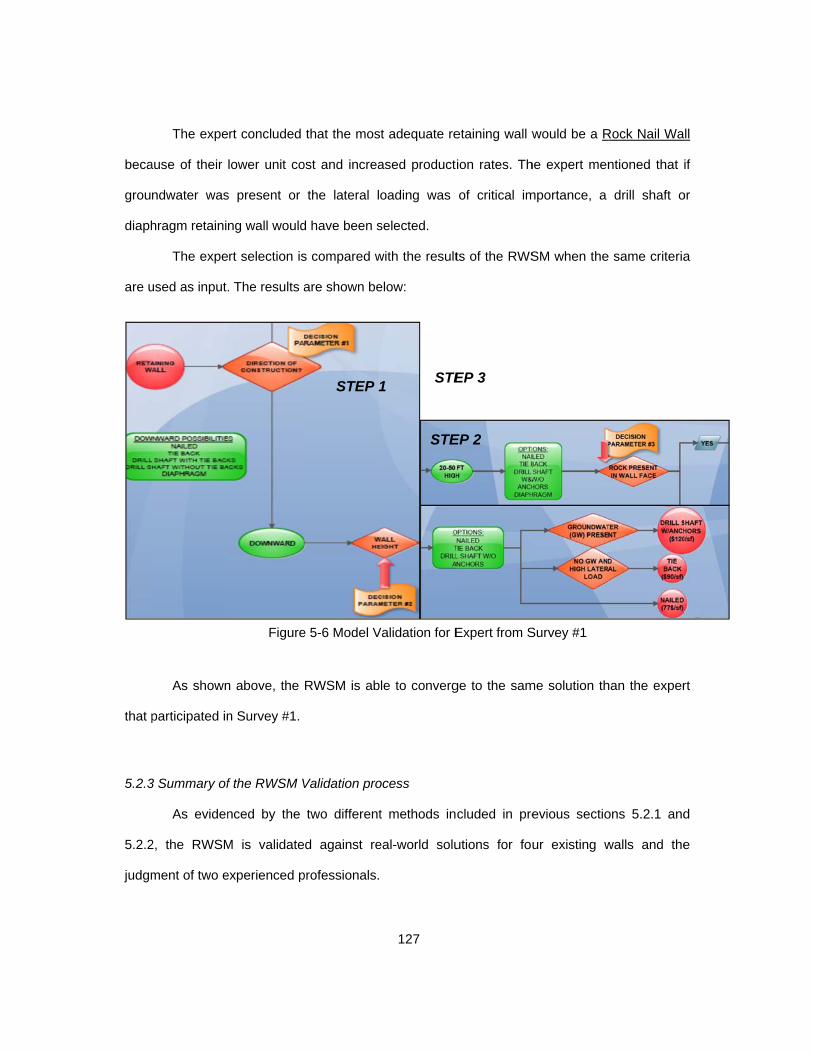
beca
grou
diaph
are u
that p
5.2.3
5.2.2
judgm
The expe
ause of their
ndwater was
hragm retainin
The expe
used as input.
As shown
participated in
3 Summary of
As eviden
2, the RWSM
ment of two e
rt concluded
lower unit co
s present or
ng wall would
rt selection is
. The results a
n above, the
n Survey #1.
f the RWSM V
nced by the
M is validate
experienced p
Figure
that the mos
ost and increa
the lateral lo
d have been s
s compared w
are shown be
RWSM is ab
Validation pro
two different
d against re
professionals.
STEP 1
e 5-6 Model V
127
t adequate re
ased product
oading was
selected.
with the result
elow:
le to converg
ocess
t methods in
eal-world solu
1
STE
STE
Validation for E
etaining wall w
ion rates. Th
of critical im
ts of the RWS
ge to the sam
cluded in pre
utions for fou
EP 2
EP 3
Expert from S
would be a R
he expert men
mportance, a
SM when the
me solution th
evious sectio
ur existing w
Survey #1
Rock Nail Wa
ntioned that i
drill shaft o
e same criteria
han the exper
ons 5.2.1 and
walls and the
ll
if
or
a
rt
d
e

128
These two validations provide the required confidence level in the RWSM for its use in
preliminary studies and wall selection. As evidenced by these validation processes, the
information required by the model to converge is small, and commonly occurs within 3 or 4
steps.
5.3 Analysis and Evaluation of the Retaining Wall Selection Model (RWSM)
Once the model was validated by the aforementioned two phase approach as detailed
in Sections 5.2.1 and 5.2.2, a final analysis and evaluation is performed.
Although limiting for some of the options and the multivariable analysis required, the
graphical approach implemented in the RWSM constitutes a quick tool that enables easy
analysis and decision processes for engineers of all levels of experience.
The model is based on general parameters and constraints, project specific restrictions
are not considered and therefore an individual analysis is required to account for them. For
example, one of the “no-go” factors identified during the interview process for anchored/nailed
walls was the restrictions regarding subsurface ROW. If a downward wall higher than 50 feet is
required in existing soil where ROW prevents the use of anchors, highly specialized solutions
would be required, and these would be outside the scope of the RWSM.
It was identified that the influence of the unit cost during the selection process is very
limited. Just by considering geometrical, geotechnical and logistic constraints, the model is able
to converge to one single solution in the majority of the cases. The only exception is the
“Cantilever Vs. MSE Vs. Wire for less than 10 ft. with availability of lateral space” where the
lower unit cost for the wire mesh wall determined its selection. Similarly, the production rates
developed during the data collection phase have a limited affection in the selection process.
The model successfully converged to equal solutions in the six validation cases
presented in Sections 5.2.1 and 5.2.2. Therefore, it is concluded that the model can be useful
for real-world wall determination. The validation performed to the two subject experts showed

129
that the model was able to replicate the reasoning process performed by them to determine the
most suitable type of retaining wall.
The model is particularly based in three parameters. These are direction of
construction, height and soil type. The determination of these project constraints enable the
reduction of the potential wall types to just one or two solutions.
130
Chapter 6
Conclusions and Recommendations for Future Research
6.1 Summary and Conclusions
In the present research, retaining wall selection processes have been investigated.
Retaining Walls constitute one of the most important elements in most construction projects,
therefore a proper decision process is key for the overall project outcome. Wall Selection has
been traditionally performed by experience as reported by Hancher et al. (1992).
Chong (2005) showed that rather than relying on pure experience or improperly
appraised historical records, a comprehensive research would lead to more accurate data and
decision-making processes. Yang (2004) showed that some construction problems cannot be
represented nor resolved with the use of conventional scientific algorithms, thus the need of
different systems and approaches. Although experience-oriented problems represent a suitable
alternative where solutions are obtained by previous experience solutions, Hess and Adams
(1995) indicated that the majority of the engineers tend to restrict themselves to select retaining
wall types that they have experience with.
These studies established the need of developing knowledge-based systems in order to
better determine the most adequate solutions for the different project needs. Although previous
research have attempted to develop knowledge-based models, no single reference has been
identified to include factors as critical as direction of construction, unit costs and production
rates as driving parameters for the selection process.
Existing literature in regards to retaining wall advantages and disadvantages, as well as
the particular drivers for each wall type is limited, and in order to fill these gaps, the present
research gathered additional information for use in the selection model.
The data collection campaign performed in the present Thesis consisted in a series of
five field observations, five interviews and eight surveys to expert subjects undertaken to collect
data in regards to retaining wall such as limiting factors, common construction issues, unit costs

131
or production rates. This data was gathered with the literature references, author’s previous
experiences and known walls in order to develop a retaining wall database for use in both the
selection model and future needs during preliminary studies.
Retaining Wall Database
A specific data collection campaign was developed to obtain the lacking data identified
during the literature review. Five field observations in DFW transportation construction projects
were performed to develop typical unit costs and productions for the most commonly used
retaining wall types. Additionally, specially designed survey and interview forms were used with
13 expert subjects to obtain additional data for use in both the database and selection model.
In addition to unit costs and production rates, additional important data was collected in
regards to factors for wall determination, areas where information lacks, limiting heights,
groundwater affection, maintenance needs, selection drivers, common construction issues and
rankings (in order of construction difficulty, unit costs and duration of construction). The
common construction issues can be particularly useful for development of QA/QC programs to
be implemented in construction as wall failure represent a recurrent issue in civil construction.
Retaining Wall Selection Model (RWSM)
Using the information collected in both the literature review, field observations, surveys
and interviews, a Retaining Wall Selection Model (RWSM was developed. The critical driving
factors for each type of wall, as well as those “no-go” parameters that determine the non-
adequacy under certain conditions were identified.
An Imperialistic Chaotic model following the research of Poubarba (2012) was
developed. For a certain condition, the different potential solutions are compared to determine
the most adequate solution. The remaining “empire” (wall) after the sequence of comparisons is
selected as the optimum solution for the set of constraints used as model input.
The interviews and surveys performed with expert subjects showed a general
agreement in regards to the gabion and sheet walls. 95% of the consulted engineers responded

132
that these two types of walls would not be considered as a potential solution for a permanent
retaining wall to be constructed in a transportation project and therefore these two types were
not be considered as potential options for use in the model.
The RWSM is implemented in a graphical flowchart framework that return quick
solutions in cases where limited information is available. The model is validated in a two-phase
approach. First, four known walls were used as real-world model evaluations where these wall’s
constraints were used as input for the model, where all solutions returned matching the wall
types constructed in the four cases. Additionally, two experts from the interview and survey data
collection phases were selected to determine the most adequate wall type for a given set of
conditions. The model was able to replicate the reasoning process and yield same wall types
than the ones concluded by the experts.
It was identified that the influence of the unit cost during the selection process was very
limited. Just by considering geometrical, geotechnical and logistic constraints, the model is able
to converge to one single solution in the majority of the cases.
The final results of this research were the development of a retaining wall database and
the Retaining Wall Selection Model (RWSM). These can be used as a starting point to
determine the most suitable permanent retaining wall for a given set of conditions.
The model can also result highly useful as a selection tool during preliminary and
feasibility studies where the information is limited. Only by the identification of few driving
factors, the model is able to return one single optimum retaining wall type.
The presented database fills the gaps of data in regards to those considerations that
are not commonly available in the existing references due to lack of research or commercial
implications. This database is intended to allow engineers to perform preliminary cost
estimations, duration calculations and wall comparisons in initial phases of construction
projects.

133
6.2 Recommendations for Future Research
The following recommendations are presented for future studies in regards to the
retaining wall types, costs, production rates, applicability and development of selection models.
1. Analyze each one of the retaining walls by different height ranges, determining their
typical costs and production rates for each. Incorporate the influence of the wall
height in the unit costs and production rates to develop a database that can
accurately represent a wider spectrum of projects.
2. Analyze the influence of different geotechnical parameters in the unit costs of each
type of wall. For example by determining the unit cost of MSE Vs. internal friction
angle of the backfill for several different combinations to determine a correlation.
3. Perform extended observations for several walls of the same type to better address
the project specific variability in unit costs and production rates. Include
geosynthetic reinforcement for the MSE Walls in addition to metallic straps.
4. Develop a more detailed unit cost database, incorporating actual Ownership &
Operating costs for the different equipment involved, to reduce the dependence in
companies’ costs presented.
5. Extend the interviews and surveys campaign to personnel in smaller size projects,
as well as State Engineers, to develop a wider scope and more representative data
pool to develop both the database and the selection model. Analyze the impact of
the respondent’s role in the responses obtained.
6. Implement the selection model into an easy-to-use programming language platform
such as Visual Basic® or Macro®, for web-based applications. A series of drop-
down menus in a cascade selection process appears to be a promising solution.
7. Incorporate studies in unit costs and production rates from different geographical
areas to address the variability in costs, construction processes, weather,
availability of materials, equipment and labor, etc.

134
Appendix A
Abreviations used in this Thesis

135
ANOVA - Analysis Of Variance
ASCE – American Society of Civil Engineers
ASD – Allowable Strength Design
ASTM – American Society for Testing and Materials
CASTLES - Case-Based Retaining Wall Selection System
CIP – Cast in Place
D.S. – Drill Shaft
DFW – Dallas-Fort Worth
DMS – Departamental Material Specifications
EMS – Environmental Management System
ES – Expert System
FHWA – Federal Highway Administration
ICA – Imperialistic Chaotic Algorithm
KBES - Knowledge Based Expert System
LBJ – Lyndon Baines Johnson
LRFD – Load and Resistance Factor Design
MSE – Mechanically Stabilized Earth
OBS - Observation
OCEW – On Center Each Way
PTI – Post-Tensioning Institute
QC/QA – Quality Control and Quality Assurance
RBKS - Rule-Based Knowledge System
RI – Rule Induction
ROW – Right Of Way
RWSM – Retaining Wall Selection Model
RWSS - Retaining Wall Selection System
STD. DEV – Standard Deviation
TDOT – Tennessee Department of Transportation
TXDOT – Texas Department of Transportation
W/ - With
W/O - Without
WWM – Welded Wire Mesh

136
Appendix B
Completed Forms of Surveys performed to Expert Subjects during the data collection
campaign

137
Survey Recipient: #1 Years of experience: Position: Construction Manager Date: 03/10/2014 Area of expertise: Heavy civil PPP Construction Management
Country where highest experience: Ireland/Chile
Please list the 3 main factors you consider when developing unit costs for retaining walls in general terms:
Cost of materials involved in wall construction Design and monitoring costs
Subcontractor availability Please list the 3 main factors you consider when developing production rates for
retaining walls in general terms: Accessibility and readily available supply materials
Need to waiting times (such as concrete/grout curing) Site specific constraints (schedule, conflicts, noise reduction, etc.).
Please list the 3 main factors to consider when developing unit costs for retaining walls for the following types:
o Cast in place = Presence of nearby batch plants, cost of reinforcing steel and formwork
based on their complexity
o Sheet pile wall = I would not consider this wall
o Drill Shaft wall (w/o tie backs) =Cranes and rigging, cost of spoil disposal, availability
of drilling subcontractors
o Diaphragm wall = Cost of reinforcement steel, subcontractor fees, cranes and
rigging. o Drill Shaft wall (w/ tie backs) = Combine
above and below o Wire mesh wall = Cost of backfill, proprietary systems cost, compaction
o Tie Back wall = Material cost, requirements for testing and stressing,
availability of subcontractors
o MSE Wall = Precast panels cost, availability of selected backfill, accesses
and supply complications o Nailed wall =Material cost, grout supply or
site mixing, availability of subcontractors o Gabion wall = I would not consider this
wall What wall height would be the limit of economically feasible construction for these
walls in your opinion?
o Cast in place = 25 ft o Sheet pile wall = I would not consider
this wall o Drill Shaft wall (w/o tie backs) = 60 ft o Gravity Wall = 10 ft o Drill Shaft wall (w/ tie backs) = 85 ft o Wire mesh wall = 15 ft
o Tie Back wall = 65 ft o MSE Wall = 40 ft
o Nailed wall = 35 ft o Gabion wall = I would not consider this
wall Which typical unit cost do you consider when performing preliminary analysis of
these retaining wall types?
o Cast in place = 55$/SF. o Sheet pile wall = I would not consider
this o Drill Shaft wall (w/o tie backs) = 80$/SF. o Gravity Wall = 45$/SF.
o Drill Shaft wall (w/ tie backs) = 105 $/SF. o Wire mesh wall = 40$/SF. o Tie Back wall = 85$/SF. o MSE Wall = 55$/SF. o Nailed wall = 70$/SF. o Gabion wall = I would not consider this

138
Which typical production rates do you consider when performing preliminary analysis of these retaining wall types?
o Cast in place = 600 SF/day o Sheet pile wall = I would not
consider this wall o Drill Shaft wall (w/o tie backs) = 350 SF/day o Gravity Wall = 450 SF/day o Drill Shaft wall (w/ tie backs) = 250 SF/day o Wire mesh wall = 800 SF/day
o Tie Back wall = 450 $/SF. o MSE Wall = 1150 SF/day
o Nailed wall = 625 SF/day o Gabion wall = I would not consider
this wall Which 3 wall types would you recommend for remote areas where specialized
workforce is limited? MSE Walls
Soil/Rock Nails Concrete cast in place walls

139
Survey Recipient: #2 Years of experience: Position: Segment Construction Manager Date: 03/11/2014 Area of expertise: Heavy civil PPP Construction
Country where highest experience: Ireland
Please list the 3 main factors you consider when developing unit costs for retaining walls in general terms:
Auxiliary equipment required Potential use of existing crews and equipment
Cost of materials required Please list the 3 main factors you consider when developing production rates for
retaining walls in general terms: Possibility of continuous production and extended shifts
Degree of specialization required by subcontractors Potential of conflict between different activities
Please list the 3 main factors to consider when developing unit costs for retaining walls for the following types:
o Cast in place = Availability of concrete, height and one/two face formwork required
o Sheet pile wall = I would not consider this wall
o Drill Shaft wall (w/o tie backs) = Type of soil, depth and clearance for cage introduction with normal methods
o Diaphragm wall = Depth, width of panels and type of joint/waterproofing
required o Drill Shaft wall (w/ tie backs) = Cost of materials, specialized subcontractors and
phasing
o Wire mesh wall = Maximum basket height, width and requirements for
backfill o Tie Back wall = Need for monitoring,
spacing of tie backs, availability of subcontractors
o MSE Wall = Requirements for selected fill and availability onsite,
maximum backfill lift, length of straps o Nailed wall = Spacing of nails, length and
corrosion protection requirements o Gabion wall = I would not consider
this wall What wall height would be the limit of economically feasible construction for these
walls in your opinion?
o Cast in place = 30 ft. o Sheet pile wall = I would not consider
this wall o Drill Shaft wall (w/o tie backs) = 65 ft. o Gravity Wall = 8 ft. o Drill Shaft wall (w/ tie backs) = 90 ft. o Wire mesh wall = 25 ft.
o Tie Back wall = 60 ft. o MSE Wall = 50 ft.
o Nailed wall = 40 ft. o Gabion wall = I would not consider
this wall Which typical unit cost do you consider when performing preliminary analysis of
these retaining wall types?
o Cast in place = 60$/SF. o Sheet pile wall = I would not consider
this wall o Drill Shaft wall (w/o tie backs) = 90$/SF. o Gravity Wall = 40$/SF.
o Drill Shaft wall (w/ tie backs) = 115 $/SF. o Wire mesh wall = 40$/SF. o Tie Back wall = 80$/SF. o MSE Wall = 50$/SF.
o Nailed wall = 65$/SF. o Gabion wall = I would not consider
this wall

140
Which typical production rates do you consider when performing preliminary analysis of these retaining wall types?
o Cast in place = 650 SF/day o Sheet pile wall = I would not consider
this wall o Drill Shaft wall (w/o tie backs) = 450
SF/day o Gravity Wall = 150 SF/day
o Drill Shaft wall (w/ tie backs) = 350 SF/day
o Wire mesh wall = 850 SF/day
o Tie Back wall = 500 $/SF. o MSE Wall = 1250 SF/day
o Nailed wall = 700 SF/day o Gabion wall = I would not consider
this wall Which 3 wall types would you recommend for remote areas where specialized
workforce is limited? Concrete cast in place
MSE Wall Wire mesh wall

141
Survey Recipient: #3 Years of experience: Position: Sub-Segment Construction Manager
Date: 03/10/2014
Area of expertise: Construction Management
Country where highest experience: Spain
Please list the 3 main factors you consider when developing unit costs for retaining walls in general terms:
Anticipated delays due to weather and external affection
Accessibility and space for storage
Cost of subcontractors and suppliers Please list the 3 main factors you consider when developing production rates for
retaining walls in general terms:
Anticipated delays due to weather and external affection
Accessibility and space for storage
Potential for weekend work and double shifts
Please list the 3 main factors to consider when developing unit costs for retaining walls for the following types:
o Cast in place = Space available and need for shoring or traffic control
o Sheet pile wall = I have not encountered this for permanent construction in
transportation projects
o Drill Shaft wall (w/o tie backs) = Cost of rebar cages, cost of drilling and type of
soil to be drilled
o Diaphragm wall = I do not have experience with this type of wall
o Drill Shaft wall (w/ tie backs) = I do not have experience with this type of wall
o Wire mesh wall = Cost of fill and materials needed for wire and filter baskets
o Tie Back wall = I do not have experience with this type of wall
o MSE Wall = Space available and need for shoring or traffic control
o Nailed wall = Height for the drilling equipment to work at, maximum step between rows, cost of material at wall
location
o Gabion wall = Availability of aggregates for basket filling, availability of local
experience in gabion fabrication and gabion size
What wall height would be the limit of economically feasible construction for these walls in your opinion?
o Cast in place = 20 ft. o Sheet pile wall = I have not encountered
this for permanent construction in transportation projects
o Drill Shaft wall (w/o tie backs) = 60 ft. o Gravity Wall = 12 ft. o Drill Shaft wall (w/ tie backs) = I do not
have experience with this type of wall o Wire mesh wall = 30 ft.
o Tie Back wall = I do not have experience with this type of wall
o MSE Wall = 50 ft.
o Nailed wall = 45 ft. o Gabion wall = 8 ft.

142
Which typical unit cost do you consider when performing preliminary analysis of these retaining wall types?
o Cast in place = 70 $/SF. o Sheet pile wall = I have not encountered
this for permanent construction in transportation projects
o Drill Shaft wall (w/o tie backs) = 85 $/SF.
o Gravity Wall = 50 $/SF.
o Drill Shaft wall (w/ tie backs) = I do not have experience with this type of wall
o Wire mesh wall = 45 $/SF.
o Tie Back wall = I do not have experience with this type of wall
o MSE Wall = 55 $/SF.
o Nailed wall = I do not have experience with this type of wall
o Gabion wall = 350 SF/day
Which typical production rates do you consider when performing preliminary analysis of these retaining wall types?
o Cast in place = 550 SF/day o Sheet pile wall = I have not encountered
this for permanent construction in transportation projects
o Drill Shaft wall (w/o tie backs) = 350 SF/day
o Gravity Wall = 250 SF./day
o Drill Shaft wall (w/ tie backs) = I do not have experience with this type of wall
o Wire mesh wall = 850 SF/day
o Tie Back wall = I do not have experience with this type of wall
o MSE Wall = 1000 SF/day
o Nailed wall = I do not have experience with this type of wall
o Gabion wall = 50 $/SF.
Which 3 wall types would you recommend for remote areas where specialized workforce is limited?
Concrete cast in place
MSE Wall
Gabion Wall

143
Survey Recipient: #4 Years of experience: Position: Project Manager Date: 03/06/2014 Area of expertise: Project Management Country where highest experience: USA
Please list the 3 main factors you consider when developing unit costs for retaining walls in general terms:
Previous experience with wall Testing and instrumentation requirements
Cost of materials, labor and equipment at wall location Please list the 3 main factors you consider when developing production rates for
retaining walls in general terms: Previous experience with wall
Accessibility and space for storage Need for movement monitoring and control
Please list the 3 main factors to consider when developing unit costs for retaining walls for the following types:
o Cast in place = Use of on-hand formwork, need for rebar at the stem, wall panel length
o Sheet pile wall = Only used for temporary shoring with sheet reuse,
cannot compare with other types o Drill Shaft wall (w/o tie backs) = Need for casing, underwater concrete, shaft spacing
o Diaphragm wall = Depth, need for slurry and cage reinforcement
o Drill Shaft wall (w/ tie backs) = Add the availability of local specialized tie back
companies to the costs included for the case w/o anchors
o Wire mesh wall = Availability of on-site material for backfill, basket size and lateral space for machinery movement
o Tie Back wall = Total tie back lengths and spacing, plates and studs, fascia panel?
o MSE Wall = Panel size, length of straps and backfill lift thickness
o Nailed wall = Face requirements, length and spacing of tie backs, corrosion protection
o Gabion wall = I would not consider this wall
What wall height would be the limit of economically feasible construction for these walls in your opinion?
o Cast in place = 25 ft. o Sheet pile wall = Only used for
temporary shoring with sheet reuse, cannot compare with other types
o Drill Shaft wall (w/o tie backs) = 50 ft. o Gravity Wall = 10 ft. o Drill Shaft wall (w/ tie backs) = 80 ft. o Wire mesh wall = 25 ft.
o Tie Back wall = 60 ft. o MSE Wall = 60 ft. o Nailed wall = 50 ft. o Gabion wall = I would not consider it
Which typical unit cost do you consider when performing preliminary analysis of these retaining wall types?
o Cast in place = 75$/SF. o Sheet pile wall = Only used for
temporary shoring with sheet reuse, cannot compare with other types
o Drill Shaft wall (w/o tie backs) = 95 $/SF. o Gravity Wall = 70 $/SF. o Drill Shaft wall (w/ tie backs) = 130$/SF. o Wire mesh wall = 55 $/SF.
o Tie Back wall = 85 $/SF. o MSE Wall = 60 $/SF. o Nailed wall = 75 $/SF. o Gabion wall = I would not consider it

144
Which typical production rates do you consider when performing preliminary analysis of these retaining wall types?
o Cast in place = o Sheet pile wall = Only used for
temporary shoring with sheet reuse, cannot compare with other types
o Drill Shaft wall (w/o tie backs) = o Gravity Wall = 100 SF/day o Drill Shaft wall (w/ tie backs) = o Wire mesh wall = 1000 SF/day
o Tie Back wall = o MSE Wall = 1500 SF/day
o Nailed wall = o Gabion wall = I would not consider
this wall Which 3 wall types would you recommend for remote areas where specialized
workforce is limited? Sheet pile Wall Concrete wall
MSE Wall

145
Survey Recipient: #5 Years of experience: Position: Project Manager Date: 03/04/2014 Area of expertise: Project Management Country where highest experience: USA
Please list the 3 main factors you consider when developing unit costs for retaining walls in general terms:
Wall location and access routes Potential for "just in time" purchasing policy
Traffic control requirements Please list the 3 main factors you consider when developing production rates for
retaining walls in general terms: Logic between prior and after activities
Quality and experience of subcontractors Previous experience with wall
Please list the 3 main factors to consider when developing unit costs for retaining walls for the following types:
o Cast in place = Potential use of local labor and existing formwork, reinforcement
o Sheet pile wall = I do not have experience with this type of wall
o Drill Shaft wall (w/o tie backs) = Current cost of rebar, current cost of concrete, cost of
subcontractors
o Diaphragm wall = I do not have experience with this type of wall
o Drill Shaft wall (w/ tie backs) =Current cost of rebar, current cost of concrete, cost of
subcontractors
o Wire mesh wall = Need for shoring, requirements for selected fill, cost of
proprietary systems for baskets
o Tie Back wall = Subcontractor availability, spacing and length of tie backs
o MSE Wall =Need for shoring, requirements for selected fill, cost of proprietary systems for panels/straps
o Nailed wall = Size of bars, length of bars, water/cement relation for grout
o Gabion wall = Unknown
What wall height would be the limit of economically feasible construction for these walls in your opinion?
o Cast in place = 25 ft. o Sheet pile wall = I do not have experience with this type of wall
o Drill Shaft wall (w/o tie backs) = 55 ft. o Gravity Wall = 15 ft. o Drill Shaft wall (w/ tie backs) = I do not
have experience with this type of wall o Wire mesh wall = 30 ft.
o Tie Back wall = 55 ft. o MSE Wall = 44 ft.
o Nailed wall = 30 ft. o Gabion wall = I do not have
experience with this type of wall Which typical unit cost do you consider when performing preliminary analysis of
these retaining wall types?
o Cast in place = 65$/SF. o Sheet pile wall = I do not have experience with this type of wall
o Drill Shaft wall (w/o tie backs) = 85$/SF. o Gravity Wall = 60$/SF. o Drill Shaft wall (w/ tie backs) = 125 $/SF. o Wire mesh wall = 55$/SF.
o Tie Back wall = 95$/SF. o MSE Wall = 65$/SF. o Nailed wall = 65$/SF. o Gabion wall = I would not consider l
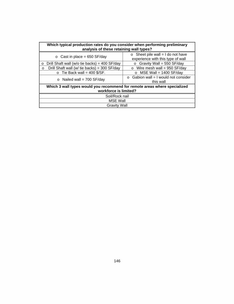
146
Which typical production rates do you consider when performing preliminary analysis of these retaining wall types?
o Cast in place = 650 SF/day o Sheet pile wall = I do not have experience with this type of wall
o Drill Shaft wall (w/o tie backs) = 400 SF/day o Gravity Wall = 550 SF/day o Drill Shaft wall (w/ tie backs) = 300 SF/day o Wire mesh wall = 950 SF/day
o Tie Back wall = 400 $/SF. o MSE Wall = 1400 SF/day
o Nailed wall = 700 SF/day o Gabion wall = I would not consider
this wall Which 3 wall types would you recommend for remote areas where specialized
workforce is limited? Soil/Rock nail
MSE Wall Gravity Wall

147
Survey Recipient: #6 Years of experience: Position: Chief Executive Officer Date: 03/12/2014 Area of expertise: Heavy civil PPP Construction Management
Country where highest experience: Ireland
Please list the 3 main factors you consider when developing unit costs for retaining walls in general terms:
Access and storage conditions New crews or continuing work (learning curve)
Availability of raw materials (concrete aggregates, backfill, etc.) Please list the 3 main factors you consider when developing production rates for
retaining walls in general terms: Anticipated weather affection
Number of weekdays and production cycles Materials involved and degree of specialty of local subcontractor
Please list the 3 main factors to consider when developing unit costs for retaining walls for the following types:
o Cast in place = Cost of concrete, potential for longer panels and formwork reuse
o Sheet pile wall = I have never worked with this type
o Drill Shaft wall (w/o tie backs) = Length of shafts, spacing between shafts, type of soil
o Diaphragm wall = Slurry needs, storage areas and distance to
reinforcement preparation area
o Drill Shaft wall (w/ tie backs) = Same as above plus cost of subcontractors for anchor operations
o Wire mesh wall = Basket length and vertical spacing, requirements
for backfill
o Tie Back wall = Tie back length, spacing and requirements for materials
o MSE Wall = Straps length and vertical spacing, requirements for
backfill o Nailed wall = Type of soil, potential for use of
more than one rig, lateral space for material preparation and storage
o Gabion wall = Availability of aggregates for basket filling
What wall height would be the limit of economically feasible construction for these walls in your opinion?
o Cast in place = o Sheet pile wall = I have never
worked with this type o Drill Shaft wall (w/o tie backs) = 50 ft. o Gravity Wall = 10 ft. o Drill Shaft wall (w/ tie backs) = 70 ft. o Wire mesh wall = 30 ft.
o Tie Back wall = 65 ft. o MSE Wall = 50 ft. o Nailed wall = 30 ft. o Gabion wall = 20 ft.
Which typical unit cost do you consider when performing preliminary analysis of these retaining wall types?
o Cast in place = 65$/SF. o Sheet pile wall = I would not
consider this wall o Drill Shaft wall (w/o tie backs) = 95$/SF. o Gravity Wall = 55$/SF.
o Drill Shaft wall (w/ tie backs) = 120 $/SF. o Wire mesh wall = 35$/SF. o Tie Back wall = 85$/SF. o MSE Wall = 60$/SF.
o Nailed wall = o Gabion wall = 65$/SF.

148
Which typical production rates do you consider when performing preliminary analysis of these retaining wall types?
o Cast in place = 750 SF/day o Sheet pile wall = I have never
worked with this type o Drill Shaft wall (w/o tie backs) = 550 SF/day o Gravity Wall = 350 SF/day o Drill Shaft wall (w/ tie backs) = 450 SF/day o Wire mesh wall = 700 SF/day
o Tie Back wall = 400 $/SF. o MSE Wall = 1250 SF/day o Nailed wall = 600 SF/day o Gabion wall = 450 SF/day
Which 3 wall types would you recommend for remote areas where specialized workforce is limited? Concrete cast in place
MSE Wall Wire mesh wall

149
Survey Recipient: #7 Years of experience: Position: Sub-Segment Construction Manager Date: 03/12/2014 Area of expertise: Construction Management Country where highest experience: USA
Please list the 3 main factors you consider when developing unit costs for retaining walls in general terms:
Wall location and traffic control needs Degree of specialization required by subcontractors
Owner requirements for noise and nuisances Please list the 3 main factors you consider when developing production rates for
retaining walls in general terms: Wall location and traffic control needs
Degree of specialization required by subcontractors Owner requirements for noise and nuisances
Please list the 3 main factors to consider when developing unit costs for retaining walls for the following types:
o Cast in place = Availability of formwork already in use, potential for rebar cage
preparation at ground level, need for shoring
o Sheet pile wall = I have never worked with this type
o Drill Shaft wall (w/o tie backs) = Soil hardness, presence of groundwater, casing
requirements
o Diaphragm wall = Wall spacing, potential for cage preparation nearby,
dump site distance o Drill Shaft wall (w/ tie backs) = Combine
upper and lower responses o Wire mesh wall = Need for shoring,
type of backfill, fill storage potential o Tie Back wall = Complication of system, presence of groundwater, testing/loading
requirements
o MSE Wall = Need for shoring, aesthetic requirements for panels, panel
size and number of straps o Nailed wall = Availability of lateral space,
potential for machinery quick movement, length of nails
o Gabion wall = I have never worked with this type
What wall height would be the limit of economically feasible construction for these walls in your opinion?
o Cast in place = 35 ft. o Sheet pile wall = I have never
worked with this type o Drill Shaft wall (w/o tie backs) = 70 ft. o Gravity Wall = 10 ft. o Drill Shaft wall (w/ tie backs) = 90 ft. o Wire mesh wall = 20 ft.
o Tie Back wall = 75 ft. o MSE Wall = 45 ft.
o Nailed wall = 50 ft. o Gabion wall = I would not consider
this wall Which typical unit cost do you consider when performing preliminary analysis of
these retaining wall types?
o Cast in place = 65$/SF. o Sheet pile wall = I have never
worked with this type o Drill Shaft wall (w/o tie backs) = 95$/SF. o Gravity Wall = 45$/SF.
o Drill Shaft wall (w/ tie backs) = 120 $/SF. o Wire mesh wall = 40$/SF. o Tie Back wall = 85$/SF. o MSE Wall = 55$/SF.
o Nailed wall = 60$/SF. o Gabion wall = I have never worked
with this type

150
Which typical production rates do you consider when performing preliminary analysis of these retaining wall types?
o Cast in place = 650 SF/day o Sheet pile wall = I have never
worked with this type o Drill Shaft wall (w/o tie backs) = 450 SF/day o Gravity Wall = 350 SF/day o Drill Shaft wall (w/ tie backs) = 350 SF/day o Wire mesh wall = 850 SF/day
o Tie Back wall = 500 $/SF. o MSE Wall = 1250 SF/day
o Nailed wall = 700 SF/day o Gabion wall = I have never worked
with this type Which 3 wall types would you recommend for remote areas where specialized
workforce is limited? Soil/Rock Nails
MSE/Wire mesh walls Concrete cast in place walls

151
Survey Recipient: #8 Years of experience: Position: Segment Construction Manager Date: 03/06/2014 Area of expertise: Construction Management
Country where highest experience: Spain/Poland
Please list the 3 main factors you consider when developing unit costs for retaining walls in general terms:
Availability of materials Miscellaneous requirements such as aesthetics, painting, finishing, etc.
Local requirements for Unions and/or sub trades Please list the 3 main factors you consider when developing production rates for
retaining walls in general terms: Supply strategy for subcontractors and materials
Potential for continuous production Availability of workspace
Please list the 3 main factors to consider when developing unit costs for retaining walls for the following types:
o Cast in place = Cost of concrete, rebar and formwork
o Sheet pile wall = Unknown
o Drill Shaft wall (w/o tie backs) = Type of soil, drill shaft spacing and reinforcement. Need for underwater concrete placement
o Diaphragm wall = Need for slurry, thickness and maximum depth
o Drill Shaft wall (w/ tie backs) = Type of soil, drill shaft spacing and reinforcement. Need for underwater concrete placement
o Wire mesh wall = Maximum basket height, availability of access and storage
of backfill o Tie Back wall = Total length, spacing and
bonded/unbonded requirements o MSE Wall = Height, panel aesthetic
requirement o Nailed wall = Spacing and maximum
step, length of nails o Gabion wall = Unknown
What wall height would be the limit of economically feasible construction for these walls in your opinion?
o Cast in place = 25 ft. o Sheet pile wall = Unknown o Drill Shaft wall (w/o tie backs) = 60 ft. o Gravity Wall = 10 ft. o Drill Shaft wall (w/ tie backs) = 85 ft. o Wire mesh wall = 15 ft.
o Tie Back wall = 65 ft. o MSE Wall = 40 ft.
o Nailed wall = 35 ft. o Gabion wall = I would not consider this
wall
Which typical unit cost do you consider when performing preliminary analysis of these retaining wall types?
o Cast in place = 55$/SF. o Sheet pile wall =Unknown o Drill Shaft wall (w/o tie backs) = 80$/SF. o Gravity Wall = 45$/SF.
o Drill Shaft wall (w/ tie backs) = 105 $/SF.
o Wire mesh wall = 40$/SF.
o Tie Back wall = 85$/SF. o MSE Wall = 55$/SF.
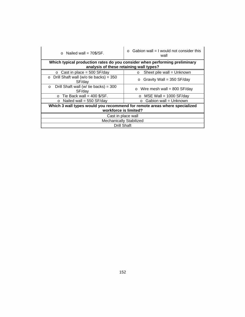
152
o Nailed wall = 70$/SF. o Gabion wall = I would not consider this
wall
Which typical production rates do you consider when performing preliminary analysis of these retaining wall types?
o Cast in place = 500 SF/day o Sheet pile wall = Unknown o Drill Shaft wall (w/o tie backs) = 350
SF/day o Gravity Wall = 350 SF/day
o Drill Shaft wall (w/ tie backs) = 300 SF/day
o Wire mesh wall = 800 SF/day
o Tie Back wall = 400 $/SF. o MSE Wall = 1000 SF/day o Nailed wall = 550 SF/day o Gabion wall = Unknown
Which 3 wall types would you recommend for remote areas where specialized workforce is limited?
Cast in place wall Mechanically Stabilized
Drill Shaft

153
Appendix C
Completed Forms of Interviews performed to Expert Subjects during the data collection
campaign

154
RETAINING WALL SELECTION INTERVIEW TO EXPERT PERSONNEL Name: Interview #1 P.E. Years of experience: 29 Position: Construction Design Manager Date: 03/12/2014 Area of expertise: Construction Technical Support and General Engineering
Location: Dallas TX
· What are the main 4 factors do you consider when determining the most appropriate types of walls for a certain location?
The geotechnical information available for the specific location, the allowable construction duration, the maximum unit cost per area of wall and the construction system/phasing of
activities. · Which are the areas where information is lacking for you to perform a proper
design? Phasing sequence and actual configuration of the wall at the different construction stages
of the general project concept · Where would you set the bar for the height of the following upward type walls?o MSE = 60 feet o Gabion wall = 30 feet o CIP = 20 feet o Wire mesh wall = 50 feet o Gravity wall = 8 feet
· Where would you set the bar for the height of the following downward type walls?
o Nailed wall = 80 feet o Drill Shaft wall (w/ anchors) = 100 feet
o Tie Back wall = 100 feet o Sheet pile wall = 30 feet with anchors o Drill Shaft wall (w/o anchors) = 25 feet o Diaphragm wall = 30 feet
· Which wall requires a higher supervision and designer expertise in your opinion?
Any wall that includes anchors and all walls of downward construction direction. · For which types of walls is the groundwater a critical factor that makes them
less appropriate? Diaphragm walls as there is no possibility of drainage unless highly specialized details
are designed and executed · What would be the three most common issues regarding the construction of
the following wall types?
o Cast in place = Formwork blowouts, incorrect rebar placement, construction joints
o Sheet pile wall = Water infiltration, unforeseen boulders that difficult the
driving processes and sheet corrosion
o Drill Shaft wall = Differing soil, water intrusions, honeycombing
o Diaphragm wall = Collapse of cages, incorrect joints and water level
unintended modifications (subsidences)
o MSE Wall = Backfill washing, strap corrosion, damage to facing
o Wire mesh wall = Ripped fabric, incorrect aggregate distribution and
excessive lift thickness o Tie Back wall = Incorrect geometry of tie
back, low-quality grout and corrosion o Gravity wall = Improper vibration, construction joints and form blowouts
o Nailed wall = Incorrect geometry of tie back, low-quality grout and corrosion
o Gabion wall = Low quality aggregate, incorrect placement, plumbness

155
Could you please rank the following walls in order of construction difficulty? (1 most dif) o Cast in place = 9 o Sheet pile wall = 5 o Drill Shaft wall = 2 o Diaphragm wall = 1 o MSE Wall = 8 o Wire mesh wall = 7 o Tie Back wall = 3 o Gravity wall = 10 o Nailed wall = 4 o Gabion wall = 6
· Which wall type do you believe to be more appropriate for fast-track needs? MSE walls for upward and nailed walls for downward construction
· Which wall types do you believe to be result in increased maintenance needs? Anchored walls, wire mesh and MSE
· What would you consider a “no-go” condition for the following types of walls (i.e. those factors that automatically discard the wall type as non-adequate?
o Cast in place = Excessive height o Sheet pile wall = Permanent configuration. Hard soils or boulders
o Drill Shaft wall = Limited cost o Diaphragm wall = Hard rock
o MSE Wall = Reduced lateral space o Wire mesh wall = Aesthetic requirements
o Tie Back wall = Schedule or limitations in subsurface ROW for the nails to be drilled
o Gravity wall = Height over 8 feet
o Nailed wall = Limitations in subsurface ROW for the nails to be drilled
o Gabion wall = Dynamic loading
· Which of the previously discussed wall types have, in your experience, been discarded or re-designed due to the lack of specialized equipment and/or
materials? Diaphragm walls and anchored walls
· Would you please rank the following upward type walls in terms of unit cost of construction? (1 most expensive)
o MSE = 3 o Gabion wall = 5 o CIP = 1 o Wire mesh wall = 4 o Gravity wall = 2 · Would you please rank the following downward type walls in terms of unit cost
of construction? (1 most expensive) o Nailed wall = 6 o Drill Shaft wall (w/ anchors) = 4 o Tie Back wall = 4 o Sheet pile wall = 5 o Drill Shaft wall (w/o anchors) = 3 o Diaphragm wall = 1 · Would you please rank the following upward type walls in terms of duration of
construction? (1 slowest) o MSE = 5 o Gabion wall = 4 o CIP = 3 o Wire mesh wall = 1 o Gravity wall = 2 · Would you please rank the following downward type walls in terms of duration
of construction? (1 slowest) o Nailed wall = 6 o Drill Shaft wall (w/ anchors) = 1 o Tie Back wall = 5 o Sheet pile wall = 3 o Drill Shaft wall (w/o anchors) = 3 o Diaphragm wall = 2

156
· What would be a standard design life for the following wall types? o Cast in place = 50 o Sheet pile wall = 1 o Drill Shaft wall = 75 o Diaphragm wall = 75 o MSE Wall = 50 o Wire mesh wall = 50 o Tie Back wall = 50 o Gravity wall = 100 o Nailed wall = 50 o Gabion wall = 50
• Is there any additional point that you believe needed to be included in this analysis?
“When performing wall analysis, I tend to develop relationships between geotechnical parameters and wall unit costs. For example, the influence of the backfill internal friction angle on the MSE wall cost per square foot of wall”.
YOUR PARTICIPATION AND RESPONSES ARE GREATLY APPRECIATED

157
RETAINING WALL SELECTION INTERVIEW TO EXPERT PERSONNEL Name: Interview #2 P.E. Years of experience: 11 Position: Technical Office Manager Date: 03/11/2014 Area of expertise: Construction Technical Support and General Engineering. Tunnels
Location: Dallas TX
· What are the main 4 factors do you consider when determining the most appropriate types of walls for a certain location?
First and foremost the direction of construction, then the height, type of soil and maximum unit cost allowed for the specific wall
· Which are the areas where information is lacking for you to perform an appropriate design?
In most cases, the actual constraints are not known at the time of the original design, later modifications, adjustments, geometry and loading determine successive changes
that altogether could have potentially made more adequate a different type. · Where would you set the bar for the height of the following upward type walls?
o MSE = 40 feet
o Gabion wall = Only used in residential construction up to 10 feet. Requires a considerable amount of
lateral space (ROW?)
o CIP = 30 feet, higher MSE o Wire mesh wall = 15 feet, would not normally use for permanent structures.
Ok for temporary retention o Gravity wall = 8 feet, if higher I would use
cantilever · Where would you set the bar for the height of the following downward type
walls?
o Nailed wall = 35 feet o Drill Shaft wall (w/ anchors) = 50 feet
with anchors o Tie Back wall = 50 feet o Sheet pile wall = 25 feet bulkhead
o Drill Shaft wall (w/o anchors) = 35 feet o Diaphragm wall = 70 feet with
anchors or tie beams · Which wall requires a higher supervision and designer expertise in your
opinion? Downward construction is in most cases more delicate than upward construction. Any wall of that direction of construction would result more sensitive in terms of design and
construction supervision · For which types of walls is the groundwater a critical factor that makes them
less appropriate? Groundwater is a key factor for most of the walls. Although with proper measures it can
be resolved for all of them, anchor capacity in saturated soils is greatly reduced therefore being more suitable a drill shaft or diaphragm wall. For upward construction, most walls
can sort groundwater with appropriate drainage measures. · What would be the three most common issues regarding the construction of
the following wall types? o Cast in place = Excessive free fall, concrete segregation/honeycombing,
incorrect reinforcement or insufficient splice length from footing
o Sheet pile wall = Unforeseen boulders, out of plumbness, excessively
reused sheets

158
o Drill Shaft wall = Differing bearing conditions, water intrusions and collapsing
holes in granular soils
o Diaphragm wall = Incorrect joint execution and water intrusions,
insufficient slurry filtering and rebar cage collapses
o MSE Wall = Clogged drainage measures, incorrect backfill and excessive gaps between
panels
o Wire mesh wall = Plumbness, backfill washing and damage to fabric
o Tie Back wall = Deviation from angle of inclination and length, lack of proper
proof/performance testing, lack of sacrificial testing to verify design assumptions
o Gravity wall = Improper concrete vibration, excessive concrete free fall
and segregation
o Nailed wall = Insufficient testing, lack of control of actual soil and insufficient nail
length
o Gabion wall = Improperly prepared subgrade, incorrect connection between
baskets, damage to wires Could you please rank the following walls in order of construction difficulty? (1 most dif)
o Cast in place = 8 o Sheet pile wall = 4 o Drill Shaft wall = 3 o Diaphragm wall = 2
o MSE Wall = 6 o Wire mesh wall = 7 o Tie Back wall = 1 o Gravity wall = 9 o Nailed wall = 5 o Gabion wall = 10
· Which wall type do you believe to be more appropriate for fast-track needs? MSE Walls and rock/soil nails
· Which wall types do you believe to be result in increased maintenance needs? Maintenance needs are highly dependent in the quality of construction, specifically in drainage measures for upward construction. Regarding downward construction, walls
without permanent facing do require repairs and preventative maintenance that for anchors can include re-stressing.
· What would you consider a “no-go” condition for the following types of walls (i.e. those factors that automatically discard the wall type as non-adequate for
them)?
o Cast in place = If MSE can be used and height is more than 15 feet is normally quicker
and more economical
o Sheet pile wall = Would only use if rest are non-feasible or for temporary
shoring in high groundwater levels and/or where movements are to be
controlled in deep excavations o Drill Shaft wall = Costly option, suitable for
high loads and soft soils o Diaphragm wall = Absence of very strict requirements for lateral moves
o MSE Wall = Heights over 40 feet
o Wire mesh wall = Normally only to be used in temporary configurations, very flexible for that can lead to issues for
roadway construction o Tie Back wall = Groundwater and fractured
soils o Gravity wall = Difficult or expensive
concrete supply
o Nailed wall = Groundwater and fractured soils
o Gabion wall = Only for projects where aesthetics is a requirement or slope stabilization. Other types result more economical in most circumstances

159
· Which of the previously discussed wall types have, in your experience, been discarded or re-designed due to the lack of specialized equipment and/or
materials? In my experience those that require specialized machinery that is either not available in remote areas or that the mobilization is not economically feasible. This would apply to
anchored walls as well as diaphragm walls. Drill rigs are more common than clamshells · Would you please rank the following upward type walls in terms of unit cost of
construction? (1 most expensive) o MSE = 3 (for a standard facing, can be 1 if
aesthetics are complicated) o Gabion wall = 4 (for low heights, if
more than 7-10 ft. results uneconomical) o CIP = 1 o Wire mesh wall = 5
o Gravity wall = 2 · Would you please rank the following upward type walls in terms of unit cost of
construction? (1 most expensive) o Nailed wall = 5 o Drill Shaft wall (w/ anchors) = 1
o Tie Back wall = 4 o Sheet pile wall = 6 o Drill Shaft wall (w/o anchors) = 3 o Diaphragm wall = 2
· Would you please rank the following upward type walls in terms of duration of construction? (1 slowest)
o MSE = 4 o Gabion wall = 3 o CIP = 1 o Wire mesh wall = 5
o Gravity wall = 2 · Would you please rank the following downward type walls in terms of duration
of construction? (1 slowest) o Nailed wall = 5 o Drill Shaft wall (w/ anchors) = 1
o Tie Back wall = 4 o Sheet pile wall = 6 o Drill Shaft wall (w/o anchors) = 2 o Diaphragm wall = 3
· What would be a standard design life for the following wall types? (years) o Cast in place = 50 o Sheet pile wall = 5 o Drill Shaft wall = 50 o Diaphragm wall = 50
o MSE Wall = 50 o Wire mesh wall = 5, temporary
retention o Tie Back wall = 50 o Gravity wall = 50 o Nailed wall = 15 o Gabion wall = 15
• Is there any additional point that you believe needed to be included in this analysis?
“For those engineers performing technical support for construction companies, being aware of the potential capabilities of each type of wall results essential to develop alternative solutions for optimized cost and schedule. Only by the understanding of the actual needs and constraints, the optimum solution can be achieved”
YOUR PARTICIPATION AND RESPONSES ARE GREATLY APPRECIATED

160
RETAINING WALL SELECTION INTERVIEW TO EXPERT PERSONNEL Name: Interview #3 P.E. Years of experience: 13 Position: Geotechnical Design Manager Date: 03/14/2014 Area of expertise: Soil retention structures in general and underground construction
Location: Dallas TX
· What are the main 4 factors do you consider when determining the most appropriate types of walls for a certain location?
Type of soil, loading requirements in terms of directions and capacity required. Availability of specialized construction personnel and equipment.
· Which are the areas where information is lacking for you to perform an appropriate design?
Normally geotechnical reports are performed in a standard manner that does not focus in the particular needs of the wall to be constructed. Also, for those projects where a cost comparison is necessary at the design level, accurate unit costs are not always readily
available. Soil type is an essential factor as well as the presence of groundwater or aggressive chemical composition in the soil.
· Where would you set the bar for the height of the following upward type walls?
o MSE = 50 feet o Gabion wall = I would not use a
gabion wall for civil construction o CIP = 25 feet o Wire mesh wall = 25 feet
o Gravity wall = 8 feet · Where would you set the bar for the height of the following downward type
walls? o Nailed wall = 35 feet, highly dependent on
soil type o Drill Shaft wall (w/ anchors) = 65 feet
with anchors
o Tie Back wall = 55 feet o Sheet pile wall = I would not use a
sheet wall in most circumstances o Drill Shaft wall (w/o anchors) = 45 feet,
more with very good stratums o Diaphragm wall = 100 feet with
anchors or tie beams · Which wall requires a higher supervision and designer expertise in your
opinion? In my experience, anchored walls can lead to great complications if the design
assumptions are not verified with proper field inspection and monitoring. Drill shaft walls also require experienced inspection for bearing stratum embedment.
· For which types of walls is the groundwater a critical factor that makes them less appropriate?
Definitely anchors and nails. For the rest of walls there are generally available solutions for groundwater control during and after construction.
· What would be the three most common issues regarding the construction of the following wall types?
o Cast in place = Improper formwork support, lack of proper drainage measures
and insufficient concrete cover
o Sheet pile wall = I would not use a sheet wall in most circumstances
o Drill Shaft wall = Improper concreting operations, insufficient embedment due to incorrect stratum inspection during drilling,
water intrusions.
o Diaphragm wall = Similar to drill shafts, with the specific concerns of
oversized cages being lifted and moved before introduction in excavated panels
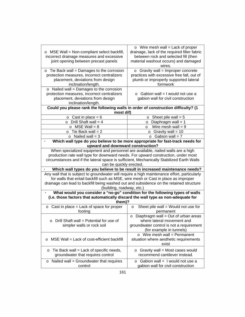
161
o MSE Wall = Non-compliant select backfill, incorrect drainage measures and excessive
joint opening between precast panels
o Wire mesh wall = Lack of proper drainage, lack of the required filter fabric
between rock and selected fill (then material washout occurs) and damaged
wires. o Tie Back wall = Damages to the corrosion protection measures, incorrect centralizers
placement, deviations from design inclination/length.
o Gravity wall = Improper concrete practices with excessive free fall, out of plumb or improperly supported lateral
formwork o Nailed wall = Damages to the corrosion protection measures, incorrect centralizers
placement, deviations from design inclination/length.
o Gabion wall = I would not use a gabion wall for civil construction
Could you please rank the following walls in order of construction difficulty? (1 most dif)
o Cast in place = 6 o Sheet pile wall = 5 o Drill Shaft wall = 4 o Diaphragm wall = 1
o MSE Wall = 8 o Wire mesh wall = 9 o Tie Back wall = 2 o Gravity wall = 10 o Nailed wall = 3 o Gabion wall = 7
· Which wall type do you believe to be more appropriate for fast-track needs for upward and downward construction?
When specialized equipment and personnel are available, nailed walls are a high production rate wall type for downward needs. For upward construction, under most
circumstances and if the lateral space is sufficient, Mechanically Stabilized Earth Walls can be quickly erected.
· Which wall types do you believe to be result in increased maintenance needs? Any wall that is subject to groundwater will require a high maintenance effort, particularly
for walls that entail backfill such as MSE, wire mesh or Cast in place as improper drainage can lead to backfill being washed out and subsidence on the retained structure
(building, roadway, etc.) · What would you consider a “no-go” condition for the following types of walls
(i.e. those factors that automatically discard the wall type as non-adequate for them)?
o Cast in place = Lack of space for proper footing
o Sheet pile wall = Would not use for permanent
o Drill Shaft wall = Potential for use of simpler walls or rock soil
o Diaphragm wall = Out of urban areas where lateral movement and
groundwater control is not a requirement (for example in tunnels)
o MSE Wall = Lack of cost-efficient backfill o Wire mesh wall = Permanent
situation where aesthetic requirements exist
o Tie Back wall = Lack of specific needs, groundwater that requires control
o Gravity wall = Most cases would recommend cantilever instead.
o Nailed wall = Groundwater that requires control
o Gabion wall = I would not use a gabion wall for civil construction

162
· Which of the previously discussed wall types have, in your experience, been discarded or re-designed due to the lack of specialized equipment and/or
materials? Tie back walls and diaphragm walls, the machinery and personnel constructing these
walls is required to be proficient with these types · Would you please rank the following upward type walls in terms of unit cost of
construction? (1 most expensive) o MSE = 3 o Gabion wall = 4 o CIP = 1 o Wire mesh wall = 5
o Gravity wall = 2 · Would you please rank the following downward type walls in terms of unit cost
of construction? (1 most expensive) o Nailed wall = 5 o Drill Shaft wall (w/ anchors) = 2
o Tie Back wall = 4 o Sheet pile wall = 6 o Drill Shaft wall (w/o anchors) = 3 o Diaphragm wall = 1
· Would you please rank the following upward type walls in terms of duration of construction? (1 slowest)
o MSE = 3 o Gabion wall = 5 o CIP = 2 o Wire mesh wall = 4
o Gravity wall = 1 · Would you please rank the following downward type walls in terms of duration
of construction? (1 slowest) o Nailed wall = 5 o Drill Shaft wall (w/ anchors) = 2
o Tie Back wall = 4 o Sheet pile wall = 6 o Drill Shaft wall (w/o anchors) = 3 o Diaphragm wall = 1
· What would be a standard design life for the following wall types? (years)
o Cast in place = 50 o Sheet pile wall = I would not use a
sheet wall in most circumstances o Drill Shaft wall = 50 o Diaphragm wall = 50
o MSE Wall = 50 o Wire mesh wall = 25 feet o Tie Back wall = 50 o Gravity wall = 50
o Nailed wall = 25 unless justified otherwise in stable solid rock
o Gabion wall = I would not use a gabion wall for civil construction
• Is there any additional point that you believe needed to be included in this analysis?
“Wall selection and design is not an easy task but it is not out of most engineer´s reach. On the other hand, the skills that make proper construction, via inspections and monitoring, result critical for the final product to be achieved. Also, groundwater and anchored walls should not be mixed unless experienced personnel are involved in the design and construction as well as movement control devices are used during and after construction”
YOUR PARTICIPATION AND RESPONSES ARE GREATLY APPRECIATED

163
RETAINING WALL SELECTION INTERVIEW TO EXPERT PERSONNEL
Name: Interview #4 Years of experience: 17 Position: Geotechnical Specialty Company Area Manager
Date: 03/04/2014
Area of expertise: Downward construction retaining structures
Location: Garland TX
· What are the main 4 factors do you consider when determining the most appropriate types of walls for a certain location?
Wall height, maximum unit cost, actual design life for project and subcontractor availability
· Which are the areas where information is lacking for you to perform an appropriate design?
Final Owner requirements, unforeseen site conditions and conflicts with other project activities, schedule requirements.
· Where would you set the bar for the height of the following upward type walls?
o MSE = 50 feet o Gabion wall = I would not use a
gabion wall for civil construction o CIP = 30 feet o Wire mesh wall = 20 feet
o Gravity wall = 10 feet · Where would you set the bar for the height of the following downward type
walls?
o Nailed wall = 40 feet o Drill Shaft wall (w/ anchors) = 80 feet
with anchors o Tie Back wall = 65 feet o Sheet pile wall = 25 feet
o Drill Shaft wall (w/o anchors) = 50 feet for rock bearing
o Diaphragm wall = 100 feet with anchors or tie beams
· Which wall requires a higher supervision and designer expertise in your opinion?
Diaphragm and drill shaft walls involve oversize rebar cages operations that can result in critical damages to personnel and workers and thus, proper inspection before lifting is
critical · For which types of walls is the groundwater a critical factor that makes them
less appropriate? Any wall that involves the introduction of an element of structural responsibility is highly affected by groundwater (i.e. nails or tie backs). Additionally, for vertical construction,
washing of backfill can lead to wall movement or even failures · What would be the three most common issues regarding the construction of
the following wall types? o Cast in place = Incorrect rebar placement, lack of proper drainage measures, improper
concrete vibration
o Sheet pile wall = I do not have experience with the construction of this
type of walls o Drill Shaft wall = Cage lifting and
introduction, plumbness, soil intrusions and no use of tremie tubes
o Diaphragm wall = As for drill shafts Cage lifting and introduction, plumbness,
soil intrusions and no use of tremie o MSE Wall = Damaged straps due to
machinery on tracks, deviation from strap length/angle and improper backfill /lift
o Wire mesh wall = Backfill, damage to wires and ripped fabric that leads to
washing

164
o Tie Back wall = As for nailed walls damage to corrosion protective measures, inclination, insufficient bonded length. Recurrent issues
during stressing and locking operations
o Gravity wall = Lack of concrete vibration, joints between placements,
subgrade preparation
o Nailed wall = Damage to corrosion protective measures, inclination, insufficient
bonded length
o Gabion wall = I do not have experience with the construction of this
type of walls Could you please rank the following walls in order of construction difficulty? (1
most dif) o Cast in place = 7 o Sheet pile wall = 5 o Drill Shaft wall = 2 o Diaphragm wall = 3
o MSE Wall = 8 o Wire mesh wall = 9 o Tie Back wall = 1 o Gravity wall = 10 o Nailed wall = 4 o Gabion wall = 6
· Which wall type do you believe to be more appropriate for fast-track needs for upward and downward construction?
For downward construction and in absence of other constraints, definitely nailed walls. MSE walls are quickly constructed for upward needs
· Which wall types do you believe to be result in increased maintenance needs? Anchored walls (tie backs, drill shafts and diaphragm with anchors) in high load situations
require not only high maintenance but also load/movement monitoring · What would you consider a “no-go” condition for the following types of walls
(i.e. those factors that automatically discard the wall type as non-adequate for them)?
o Cast in place = Excessive height of lack of space for footing
o Sheet pile wall = Would not use for permanent
o Drill Shaft wall = Reduced height and availability of space
o Diaphragm wall = Absence of specific groundwater and movement control
such as in urban areas
o MSE Wall = Corrosive soil, heights less than 15 feet
o Wire mesh wall = Would not recommend it in most circumstances
unless temporary situations o Tie Back wall = Remote areas with lack of
specialized companies o Gravity wall = Height over 5 feet, as
cantilever results more economic o Nailed wall = Corrosive soils and remote
areas with lack of specialized companies o Gabion wall = I would not use a
gabion wall for civil construction · Which of the previously discussed wall types have, in your experience, been
discarded or re-designed due to the lack of specialized equipment and/or materials?
Anchored walls due to lack of specialized equipment · Would you please rank the following upward type walls in terms of unit cost of
construction? (1 most expensive) o MSE = 4 o Gabion wall = 2 o CIP = 3 o Wire mesh wall = 5
o Gravity wall = 1 · Would you please rank the following downward type walls in terms of unit cost
of construction? (1 most expensive)

165
o Nailed wall = 6 o Drill Shaft wall (w/ anchors) = 1 o Tie Back wall = 4 o Sheet pile wall = 5
o Drill Shaft wall (w/o anchors) = 3 o Diaphragm wall = 2 · Would you please rank the following upward type walls in terms of duration of
construction? (1 slowest) o MSE = 3 o Gabion wall = 4 o CIP = 1 o Wire mesh wall = 5
o Gravity wall = 2 · Would you please rank the following downward type walls in terms of duration
of construction? (1 slowest) o Nailed wall = 6 o Drill Shaft wall (w/ anchors) = 2
o Tie Back wall = 4 o Sheet pile wall = 5 o Drill Shaft wall (w/o anchors) = 3 o Diaphragm wall = 1
· What would be a standard design life for the following wall types? (years)
o Cast in place = 50 o Sheet pile wall = Would not use
for permanent, would say 5 o Drill Shaft wall = 50 o Diaphragm wall = 50
o MSE Wall = 50 o Wire mesh wall = 15 o Tie Back wall = 50 o Gravity wall = 50
o Nailed wall = 25/50 (soil/rock) o Gabion wall = Would not use for
permanent, would say 10 • Is there any additional point that you believe needed to be included in this
analysis? "In my experience, the client needs are not clearly defined at the initial stages of the
design process. This cause improper several changes to the original design that in most cases are performed by external companies not involved in the original studies. This can lead to complications during the construction. A clear and defined specification document
during the proposal stage can lead to successful investigation, retaining wall selection, design and construction"
YOUR PARTICIPATION AND RESPONSES ARE GREATLY APPRECIATED

166
RETAINING WALL SELECTION INTERVIEW TO EXPERT PERSONNEL Name: Interview #5 P.E. Years of experience: 21 Position: Geotechnical Design Firm Principal Date: 02/27/2014 Area of expertise: Geotechnical design and engineering
Location: Dallas TX
· What are the main 4 factors do you consider when determining the most appropriate types of walls for a certain location?
Soil type, maximum height, availability of horizontal space, presence of groundwater, maximum unit cost set by owner, and speed of construction required.
· Which are the areas where information is lacking for you to perform an appropriate design?
Proper geotechnical investigation, procurement constraints not present at the time of design and actual cost of materials for the particular project to make a proper cost
evaluation that is later needed by Owners · Where would you set the bar for the height of the following upward type walls?
o MSE = 45 feet o Gabion wall = Can go up to 40 feet with high lateral space consumption
o CIP = 25 feet due to uneconomical formwork required
o Wire mesh wall = 25 feet with delicate construction and backfill control
o Gravity wall = 5 feet, if higher I would use cantilever
· Where would you set the bar for the height of the following downward walls? o Nailed wall = 35 feet o Drill Shaft wall (w/ anchors) = 65 feet
o Tie Back wall = 55 feet o Sheet pile wall = 45 feet with the
incorporation of anchors o Drill Shaft wall (w/o anchors) = 40 feet in good bearing stratum such as unweathered
rock
o Diaphragm wall = 90 feet with anchors or tie beams
· Which wall requires a higher supervision and designer expertise in your opinion?
Any anchor involving active anchors, especially during the stressing and testing operations
· For which types of walls is the groundwater a critical factor that makes them less appropriate?
Anchors and nails are highly impacted by the groundwater and although some additional considerations can be taken into account, these walls do not provide any control over the
groundwater intrusions in those cases where this is a design constraint. Most vertical construction walls are highly affected by water flows as it can cause backfill washing,
especially in the MSE and wire mesh walls. · What would be the three most common issues regarding the construction of
the following wall types? o Cast in place = Formwork system,
drainage measures and joints between placements
o Sheet pile wall = Water infiltration, unforeseen boulders that difficult the driving processes and failing anchors
o Drill Shaft wall = Cleanness of the drilled hole, supervision of spoils to confirm design
assumptions and soil intrusions/honeycombing.
o Diaphragm wall = Failing cages during lifting and introduction, excessive
sand in slurry and soil intrusions in concrete/honeycombing

167
o MSE Wall = Improper compaction, unsuitable backfill and damage to straps
o Wire mesh wall = Plumbness, backfill washing and damage to fabric
o Tie Back wall = Deviation from angle of inclination, improper sleeve connection and
incorrect testing practices
o Gravity wall = Cleanness of the area prior to concrete, support of formwork,
excessive concreting speed which leads to improper consolidations and formwork
blowouts o Nailed wall = Damaged corrosion
protection, improper locking processes and deviation from the required angle/length
o Gabion wall = Damage to wire baskets, out of plumbness and use of
rock subject to weathering Could you please rank the following walls in order of construction difficulty? (1
most dif) o Cast in place = 8 o Sheet pile wall = 5 o Drill Shaft wall = 4 o Diaphragm wall = 1
o MSE Wall = 6 o Wire mesh wall = 7 o Tie Back wall = 2 o Gravity wall = 10 o Nailed wall = 3 o Gabion wall = 9
· Which wall type do you believe to be more appropriate for fast-track needs? For upward construction MSE walls and for downward construction rock nails/tie backs
· Which wall types do you believe to be result in increased maintenance needs? Wire mesh, mechanically stabilized earth and gabion
· What would you consider a “no-go” condition for the following types of walls (i.e. those factors that automatically discard the wall type as non-adequate?
o Cast in place = Height over 20 feet o Sheet pile wall = Permanent
construction
o Drill Shaft wall = Boulders exceeding shaft diameter
o Diaphragm wall = Less than 20 feet height except in high load cases or
water control needs o MSE Wall = Flowing water and corrosive
soil/water o Wire mesh wall = Potential water flow
and need for lateral loading
o Tie Back wall = Creeping soils o Gravity wall = Height over 10 feet, soft subgrade and difficult concrete
supply
o Nailed wall = Corrosive soils o Gabion wall = Height over 15 feet, reduced lateral ROW and lateral loads
· Which of the previously discussed wall types have, in your experience, been discarded or re-designed due to the lack of specialized equipment and/or
materials?
Tie back walls mostly but also drill shaft walls and diaphragm walls
· Would you please rank the following upward type walls in terms of unit cost of construction? (1 most expensive)
o MSE = 4 o Gabion wall = 1
o CIP = 2 o Wire mesh wall = 5
o Gravity wall = 3

168
· Would you please rank the following downward type walls in terms of unit cost of construction? (1 most expensive)
o Nailed wall = 6 o Drill Shaft wall (w/ anchors) = 2
o Tie Back wall = 5 o Sheet pile wall = 4 (higher if sheet
stay) o Drill Shaft wall (w/o anchors) = 3 o Diaphragm wall = 1
· Would you please rank the following upward type walls in terms of duration of construction? (1 slowest)
o MSE = 2 o Gabion wall = 5 o CIP = 1 o Wire mesh wall = 4
o Gravity wall = 3 · Would you please rank the following downward type walls in terms of duration
of construction? (1 slowest) o Nailed wall = 5 o Drill Shaft wall (w/ anchors) = 1
o Tie Back wall = 6 o Sheet pile wall = 4 o Drill Shaft wall (w/o anchors) = 3 o Diaphragm wall = 2
· What would be a standard design life for the following wall types? (years) o Cast in place = 50 o Sheet pile wall = 10 o Drill Shaft wall = 75 o Diaphragm wall = 75
o MSE Wall = 50 o Wire mesh wall = 25 o Tie Back wall = 50 o Gravity wall = 50
o Nailed wall = 25/50 (soil/rock) o Gabion wall = 25 • Is there any additional point that you believe needed to be included in this
analysis? "Wall selection was historically driven by technical parameters but the advancements in technology, materials and design knowledge have shifted the owner requirements to those coming from economic and schedule constraints. Improved geotechnical investigations would allow more adjusted designs and longer lasting wall performances"
YOUR PARTICIPATION AND RESPONSES ARE GREATLY APPRECIATED

169
Appendix D
Completed Retaining Wall Selection Model. Flowchart.

170

171
References
Adams T.M., Barret K. and Want T. (1993). “Colorado Knowledge System for Retaining
Wall Selection”. Transportation Research Record 1406, TRB, National Research
Council. Washington, DC.
ASCE Seminar (2013): “Earth Retaining Structures, Selection, Design, Construction and
Inspection”, Pittsburgh, PA / November 7-8, 2013
Babu S. and Basha B. (2008). “Optimum Design of Cantilever Retaining Walls Using
Target Reliability Approach”. International Journal of Geomechanics, Vol. 8, No.
4, August 1, 2008. Bangalore, India.
Babu S. and Shing V. (2011) “Reliability-based load and resistance factors for soil-nail
walls”. Canadian Geotechnical Journal. Vol. 48, 2011. Toronto, Canada.
Baker S.E. and Edwards R. (2007). “How many qualitative interviews is enough? Expert
voices and early career reflections on sampling and cases in qualitative
research”. National Centre for Research Methods Review Paper. NCRM,
University of Southampton, United Kingdom.
Bierchwale et al. (1981). “Field Test and New Design Procedure for Laterally Loaded
Drilled Shafts in Clay”. FHWA/TX-81/09+211-3F The Texas Transportation
Institute. Texas A&M University. College Station, TX.
Braja M. Das. (2011). “Principles of Foundation Engineering”. Seventh Edition. Cengage
Learning Engineering. Stamford, CT.
California Building Code (2007)‚ Title 24‚ Part 2, Chapter 18A - Soils and Foundations.
Section 1806A Retaining Walls. California Department of Housing. San
Francisco, CA.

172
California Department of Transportation (2004). “Bridge Design Specifications”. Section 5
Retaining Walls. San Francisco, CA..
Cheney R. (1990): “Demonstration Projects, Volume DP-68, Permanent Ground
Anchors”. FHWA-DP-90-068-0035, Federal Highway Administration (FHWA),
Washington, DC.
Chong W. (2005). “Construction Production Rate Information System for Highway
Projects”. University of Texas at Austin. Austin, TX.
Costopoulos S. (1988). “Model Behavior of a Prestressed Tie Back”. Journal of
Geotechnical Engineering, Vol. 114, No. 10, October, 1988. Athens, Greece.
Desai, C. S., and El-Hoseiny, K. E. (2005). “Prediction of field behavior of reinforced soil
wall using advanced constitutive model.” Journal of Geotechnical Geo-
environmental Engineering, 10.1061/(ASCE)1090-0241(2005)131:6(729), 729–
739.
Driscoll D.L. (2011). “Introduction to Primary Research: Observations, Surveys, and
Interviews”. ISBN 978-1-60235-184-4. Washington, DC.
Elias, V., Christopher, B. R., and Berg, R. R. (2001). “Mechanically stabilized earth walls
and reinforced soil slopes, design and construction guidelines.” FHWA-NHI-00-
043, Federal Highway Administration (FHWA), Washington, DC.
Giarratano J. and Riley G. (2004). “Expert Systems: Principles and Programming”. Fourth
Edition, Course Technology, Boston, MA.
Golam K. et al. (2014), “Influence of Soil Reinforcement on Horizontal Displacement of
MSE Wall”. International Journal of Geomechanics, Vol. 14, No. 1, February 1,
2014.

173
Hancher, D. E., McFarland, W. F., and Alabay, R. T. (1992) “Construction Contract Time
Determination” Texas Department of Transportation Research Report. Austin,
TX.
Hess T. and Adams T.M. (1995). “Retaining Structure Selection at Project Level”.
Transportation Research Record 1474, TRB, National Research Council.
Washington, DC.
Hossain M. S. et al. (2012). “Effects of Backfill Soil on Excessive Movement of MSE
Wall”. Journal of Performance of Constructed Facilities, Vol. 26, No. 6, December
1, 2012.
Ikoma N. (1992): “Selection and Design of Temporary Retaining Walls Using Expert
Systems”. CIFE Technical Report Number 79. Stanford, CA.
Jalla R. (1999). “Design of Multiple Level Retaining Walls”. Journal of Architectural
Engineering, Vol. 5, No. 3, September, 1999. Reston, VA
Jyh-Bin Yang. (2002). “A rule induction-based knowledge system for retaining wall
selection”. Expert Systems with Applications, Volume 23, Issue 3, 1 October
2002.
Kelley K. et al. (2003) “Good practice in the conduct and reporting of survey research”.
Research Department, NHS Trust, West Sussex, UK.
Lazarte C. et al. (2003): “GEOTECHNICAL ENGINEERING CIRCULAR NO. 7 ”Soil Nail
Walls”. FHWA0-IF-03-017, Federal Highway Administration (FHWA),
Washington, DC.
Lee S. (1989). Thesis:” An expert system for the selection and design of retaining walls”.
Florida Atlantic University. Boca Raton, FL.

174
Long M. (2001). “Database for retaining wall and ground movements due to deep
excavations”. Journal of Geotechnical and Geo-environmental Engineering, Vol.
127, March 2001. Dublin, Ireland.
Metropolitan Expressway Public Corporation (1990), “Design Standards for Temporary
Structures”. August 1990. Tokyo. Japan.
Mubarak S. (2010). “Construction Project Scheduling and Control”. John Wiley and Sons,
Second Edition. New York, Hoboken. NJ.
Murawski R.S. (2001). “Analysis of Construction Production Rates using the Work
Breakdown Structure System”. University of Texas at Arlington. Arlington, TX.
Myungseok C., Ghang L. (2010): “Decision tree for selecting retaining wall systems
based on logistic regression analysis” Automation in Construction, Volume 19,
Issue 7, November 2010, Pages 917–928
Nie Y and Jyh Y. (1998): “Applying case-based reasoning technique to retaining wall
selection”. Automation in Construction, Volume 7, Issue 4, May 1998, Pages
271–283.
Obla K. and Lobo C. (2006). “Experimental Case Study Demonstrating Advantages of
Performance Specifications”. Report to the RMC Research Foundation Project
04-02. National Ready Mix Concrete Association (NRMCA). Silver Spring, MA.
[34] Offices of Structure Construction. (2008): “Foundation Manual”, California Division of
Engineering Services, Department of Transportation. San Francisco, CA.
Penn M. and Parker P. (2012). “Introduction to Infrastructure. An introduction to Civil and
Environmental Engineering”. ”. John Wiley and Sons, First Edition. New York,
Hoboken. NJ.
Petaja M.S. (1999). “Cost Comparison among three retaining wall designs”. Department
of Civil and Environmental Engineering, Lewisville, KY.

175
Pizarro F. (2013). “Retaining Wall Construction”. CE-5344 Final Graduate Project.
Arlington, TX.
Pourbaba M. et al. (2012). “A Chaotic Imperialist Competitive Algorithm for Optimum Cost
Design of Cantilever Retaining Walls”. KSCE Journal of Civil Engineering (2013)
17(5):972-979. Tabriz, Iran.
Pratt D. (2011). “Fundamentals of Construction Estimating”. Third Edition. Cengage
Learning Engineering. Clifton Park, NY.
R.S. Means Company, Inc. (2002). “R.S. Means Heavy Construction Cost Data”, 59th
Annual Edition, R.S. Means Company, Inc., Kingston, MA.
Sabatini P. et al. (1999): “GEOTECHNICAL ENGINEERING CIRCULAR NO. 4” Ground
Anchors and Anchored Systems”. FHWA-IF-99-015, Federal Highway
Administration (FHWA), Washington, DC.
Sheahan C. and Ho T. (2003) “Simplified Trial Wedge Method for Soil Nailed Wall
Analysis”. Journal of Geotechnical and Geo-environmental Engineering, Vol. 129,
No. 2, February 1, 2003. Boston, MA.
Sheu, H.B. (1996). “Application of expert systems and neural networks for retaining wall
system selection”. National Central University, Taiwan, ROC.
Strom R. and Ebelin R. (2001). “State of the Practice in the Design of Tall, Stiff, and
Flexible Tieback Retaining Walls”. US Army Corps of Engineers. Engineer
Research and Development Center. ERDC/ITL TR-01 -1 (TR INP-01-4).
Vicksburg, MS.
Tan et al. (2008) “Rapid Pullout Test of Soil Nail” Journal of Geotechnical and Geo-
environmental Engineering, Vol. 134, No. 9, September 1, 2008. Singapore,
Singapore.

176
Tennessee Department of Transportation (2012). “Earth Retaining Structures Manual”.
Revision 2.1. Nashville, TN.
Texas Department of Transportation (2004). “Standard Specifications for Construction of
Highways, Streets and Bridges.” Austin, TX.
Thomas R. and Kramer D.F. (1988). “The Manual of Construction Productivity
Measurement and Performance Evaluation”. Construction Industry Institute, May
1988.
Yang J.B. (2004) “Hybrid AI system for retaining wall selection” . Construction Innovation
2004; 4: 33–52. Department of Construction Engineering, Chung-Hua University,
Hsinchu, Taiwan, ROC.
Yau N. et al (1997). “Inducing rules for selecting retaining wall systems”. Department of
Civil Engineering, National Central University. Taiwan, ROC.
Yuwen Yang, Jian-Hua Yin, Jian-Xin Yuan, Jeff N Schulyer (2003): “An expert system for
selection of retaining walls and groundwater controls in deep excavation”.
Computers and Geotechnics, Volume 30, Issue 8, December 2003, Pages 707–
719
*Surveys performed to Eight different professionals of the Construction Industry.
February-March 2014.
*Interviews performed to Five different professionals of the Construction Industry.
February-March 2014.

177
Biographical Information
Fernando Pizarro Quintanar was born in Ciudad Real, Spain on the 4th of June
of 1985. He is the youngest son of Miguel Pizarro Barranquero and Rosario Quintanar
Sanchez-Alarcos. He received his B.S. and M. Sc. Degrees in Civil Engineering with
specialization in Geotechnical and Structural Engineering from the University of Castilla-
la-Mancha (Spain) in 2008. Once graduated, he immediately joined Ferrovial-Agroman;
Spain based Company with presence in four continents for construction and
management of a variety of infrastructure projects. After three years as Quality and
Production Manager in different construction Projects of the Spain-France High Speed
Railway in the Barcelona area (Spain), the author was offered a position in the United
States on to work in a major construction Project as the Design and Construction Quality
Manager in 2011. With the support of his Company, the author enrolled the M. Sc. at the
University of Texas at Arlington in September 2012 as a MS Candidate in Construction
Management under the supervision of Dr. Mohammad Najafi.
The author’s research interests include Construction Process Optimization,
Improvement and Automation, Construction Quality, Project Management and Control,
Public-Private-Partnerships (PPP) Contracting and Negotiation as well as technical topics
in relation with Structural and Geotechnical Engineering.
Additionally to the technical and research ones, the author’s interests include
Finance, Management, Leadership and Strategy.