theta: rapid installation and acceptance of an xc40 … rapid installation and acceptance of an xc40...
TRANSCRIPT
Theta: Rapid Installation and Acceptance of anXC40 KNL System
Kevin Harms, Ti Leggett, Ben Allen, Susan Coghlan, Mark Fahey, Ed Holohan, Gordon McPheeters, Paul RichLeadership Computing FacilityArgonne National Laboratory
Argonne, ILEmail: kharms,tleggett,bsallen,smc,mfahey,eholohan,gmcpheeters,[email protected]
Abstract—In order to provide a stepping stone from theArgonne Leadership Computing Facility’s (ALCF) world classproduction 10 petaFLOP IBM BlueGene/Q system, Mira, to itsnext generation 200 petaFLOPS 3rd generation Intel Xeon Phisystem, Aurora, ALCF worked with Intel and Cray to acquirean 8.6 petaFLOPS 2nd generation Intel Xeon Phi based systemnamed Theta. Theta was delivered, installed, integrated andaccepted on an aggressive schedule in just over 3 months. Wewill detail how we were able to successfully meet the aggressivedeadline as well as lessons learned during the process.
Index Terms—XC40; KNL; deployment; integration; accep-tance;
I. INTRODUCTION
In 2016 the Argonne Leadership Computing Facility [1](ALCF) acquired a new Cray XC40, named Theta, as part ofArgonne’s CORAL (Collaboration of Oak Ridge, Argonne andLivermore) procurement for Aurora, ALCF’s next leadershipclass supercomputer. Theta continues Argonne’s focus onmany-core processing and provides a new platform for com-putational scientists to prepare codes for the next generationof Xeon Phi platforms. Theta will become a resource underthe Innovative and Novel Computational Impact on Theoryand Experiment [2] (INCITE) 2018 program. Computationalscientists from around the world will have the opportunity tocompete for compute time on this platform. Theta will alsobe the spearhead of a new ALCF program, the ALCF DataScience Program (ADSP). This program targets non-traditionalHPC applications that focus on the areas of data analysis,machine learning, deep learning and graph analytics amongothers. The ADSP serves to explore and develop the Thetaplatform for these new scientific uses.
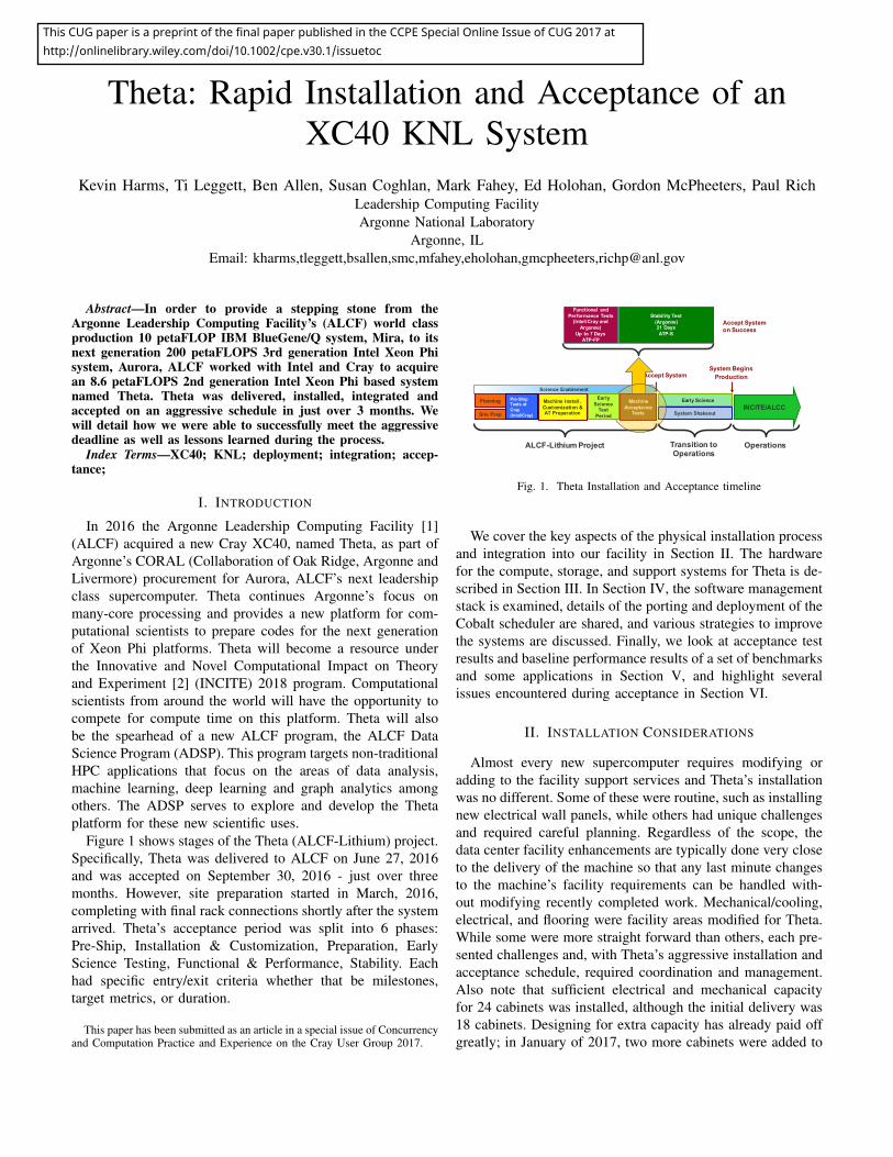
Figure 1 shows stages of the Theta (ALCF-Lithium) project.Specifically, Theta was delivered to ALCF on June 27, 2016and was accepted on September 30, 2016 - just over threemonths. However, site preparation started in March, 2016,completing with final rack connections shortly after the systemarrived. Theta’s acceptance period was split into 6 phases:Pre-Ship, Installation & Customization, Preparation, EarlyScience Testing, Functional & Performance, Stability. Eachhad specific entry/exit criteria whether that be milestones,target metrics, or duration.
This paper has been submitted as an article in a special issue of Concurrencyand Computation Practice and Experience on the Cray User Group 2017.
ALCF-Lithium Project
System Shakeout
Early ScienceMachine Acceptance
Tests
Machine Install, Customization & AT Preparation
INCITE/ALCC
Accept SystemSystem Begins
Production
Operations
Planning
Site Prep
Science Enablement
Accept Systemon Success
Functional and Performance Tests
(Intel/Cray and Argonne)
Up to 7 DaysATP-FP
Stability Test(Argonne)21 DaysATP-S
Pre-Ship Tests at Cray (Intel/Cray)
Early Science
Test Period
Transition to Operations
Fig. 1. Theta Installation and Acceptance timeline
We cover the key aspects of the physical installation processand integration into our facility in Section II. The hardwarefor the compute, storage, and support systems for Theta is de-scribed in Section III. In Section IV, the software managementstack is examined, details of the porting and deployment of theCobalt scheduler are shared, and various strategies to improvethe systems are discussed. Finally, we look at acceptance testresults and baseline performance results of a set of benchmarksand some applications in Section V, and highlight severalissues encountered during acceptance in Section VI.
II. INSTALLATION CONSIDERATIONS
Almost every new supercomputer requires modifying oradding to the facility support services and Theta’s installationwas no different. Some of these were routine, such as installingnew electrical wall panels, while others had unique challengesand required careful planning. Regardless of the scope, thedata center facility enhancements are typically done very closeto the delivery of the machine so that any last minute changesto the machine’s facility requirements can be handled with-out modifying recently completed work. Mechanical/cooling,electrical, and flooring were facility areas modified for Theta.While some were more straight forward than others, each pre-sented challenges and, with Theta’s aggressive installation andacceptance schedule, required coordination and management.Also note that sufficient electrical and mechanical capacityfor 24 cabinets was installed, although the initial delivery was18 cabinets. Designing for extra capacity has already paid offgreatly; in January of 2017, two more cabinets were added to
This CUG paper is a preprint of the final paper published in the CCPE Special Online Issue of CUG 2017 at http://onlinelibrary.wiley.com/doi/10.1002/cpe.v30.1/issuetoc
Theta and the installation was simple since no infrastructureneeded to be installed.
Mechanical work started on March 10 and completed onJune 20. The mechanical improvements included upgradingan existing water loop to provide the cooling for both Thetaand our existing 10 PF IBM BlueGene/Q (BGQ) productionsupercomputer, Mira. Having Mira and Theta share a commonwater loop presented several challenges. First, the engineeringteam had to design for the modified loop to accomodateboth the constant flow required by the BGQ direct watercooling and dynamically changing flow required by the XC40hybrid cooling system. Because Mira’s water cooling loop wasdesigned with the necessary stubs and valves to accomodatethe addition of a new water cooled system to the loop, thepiping and valves for Theta’s racks could be installed withoutany impact to the existing water loop until it was time toconnect and power on the racks. It was necessary to upgradethe impellers on the pumps serving the water loop to a largercapacity to support the increased heat load. Since the pumpswere originally installed in an N+1 configuration, the pumpscould be upgraded one at a time without impacting normalday to day operations - though the upgrades were scheduledto coincide with regular maintenance windows to reduce risk.Another interesting challenge the mechanical designers had toovercome was the programming of the pump controls when theimpellers on the two separate pumps and their correspondingcapacities were different during this transition.
Electrical work started on March 24 and completed onJune 20. We were able to make use of spare electricalcapacity already present in the data center; however, thatmeant coordinating work around Mira’s maintenance days andother data center tenants to reduce the impact of necessaryoutages. The electrical improvements were typical for such asupercomputer, including the installation of new wall panelsand whips as well as two inline PDUs; however, the electricalsubstations were on the opposite side of the data center over120 feet away. Therefore, a copper busway was installedoverhead with 6 1200 Amp busducts, above the ceiling tilesand lights, and over existing production PDUs, networkingracks, and disk racks. The actual datacenter ceiling is 20ft high, so the workers had to use a specially constructedscaffolding that could easily be separated into two parts andmoved easily among the production compute equipment whilehanging the busducts from the high ceiling. Safety awarenesswas coordinated with all the data center tenants to ensure allwere aware of the added hazards from this overhead work.
The raised floor was also upgraded to provide support forthe XC40 cabinets. While that work only took several days inreal time, the work was spread over several weeks to reducethe impact on other facility work in the data center. Theexisting floor tiles and pedestals would support a max weightindividually of 925 lb while the XC40 cabinets, inline PDUs,and Sonexion disk cabinets would all surpass this weight limit.For example, the disk cabinets would weigh 4,000 lb and covertwo tiles. Therefore the floor pedestals were upgraded to 2 mmthick steel and could support 9,000 lb, and the existing floor
tiles were replaced with FS300 tiles with support for 5,400lb. An identical floor upgrade was completed for the Mirainstallation just prior to its delivery as well.
After the new cabinets were installed, a hearing test wasconducted by the Argonne Industrial Hygiene group since thenoise level in the datacenter was noticeably higher. The reportindicated for the area around Theta that the sound in that areameasures from between 84 dBA to 93 dBA in front of Theta’sblowers. ALCF has conducted tests that show baffles on theintake blower cabinets can abate some of the noise. ALCF isalso considering acoustic barriers along exterior walls to abatenoise leakage into the building office area.
III. HARDWARE DETAILS
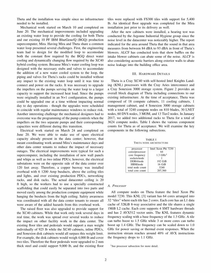
Theta is a Cray XC40 with self-hosted Intel Knights Land-ing (KNL) processors with the Cray Aries interconnect anda Cray Sonexion 3000 storage system. Figure 2 provides anoverall block diagram of Theta including connections to ourexisting infrastructure. At the time of acceptance, Theta wascomposed of 18 compute cabinets, 11 cooling cabinets, 1management cabinet, and 4 Sonexion 3000 storage cabinetswith a total of 3240 compute nodes on 810 blades, 30 LNETnodes, 60 DVS nodes, 3 MOM, and 13 Tier2 nodes. In January2017, we added two additional racks to Theta for a total of3624 compute nodes. Table I shows the various componentcounts for Theta as of acceptance. We will examine the keycomponents in the following subsections.
TABLE ITHETA NODE ARCHITECTURE
processor Intel Xeon Phi 7230cores/processor 64core frequency 1.3 GHz1
sockets/node 1DDR4/node 192 GiBHBM/node 16 GiB
total node count 3240total core count 207,360
A. Processor
All compute nodes on Theta feature the Intel Xeon Phimodel 7230. This KNL [3] variant has 64 cores arranged into32 “tiles” where each tile has 2 cores. Each core has an L1 datacache of 32KiB 8-way associative and the tile shares a single1MiB L2 cache. Each core supports 4 SMT hardware threadsand has 2 AVX512 vector units. The KNL features dynamicfrequency scaling with a base frequency of the 1.3 GHz. A tilecan turbo boost to 1.5 GHz while 3 or more cores can turboboost up 1.4 GHz. The frequency can be scaled down to 1.0GHz for power saving or thermal event responses. When theinstruction stream reaches around 40% of AVX instructionsthe frequency drops to 1.1 GHz.
1See processor subsection for more detail.
2
Sonexion 3000/lus/theta-fs0
Infiniband QDR Network
IBM ESS10 PB
/gpfs/theta-fs1
Fig. 2. Block diagram of Theta system - credit Cray, Inc.
B. Memory
The KNL memory subsystem features two types of memorywhich can be configured in several different modes. There is16 GiB of high bandwidth Multi-channel DRAM (MCDRAM)which is located on the CPU package and has a peak band-width of around 450 GiB/s and a latency of 150 ns. The Thetacompute nodes also have traditional DDR4 DRAM populatingall 6 memory channels for around 90 GiB/s of bandwidth and125 ns of latency. A unique feature of the KNL is a methodto provision the MCDRAM in different configurations at boottime. The “memory mode” determines if the MCDRAM willbe used like a last level cache for the DRAM, in whichcase the MCDRAM is not directly addressable. In this case,a Theta compute node has 128 GiB of main memory, asseen by Linux, and the hardware would transparently managethe MCDRAM as a direct-mapped cache layer. The memorymode can also be set to “flat mode” which provides directaccess to the entire MCDRAM. In flat mode the MCDRAMappears as discreetly addressable memory to Linux, with theNUMA distance set father away then DDR4 so that the OSand runtimes do not allocate any of this memory by default,leaving it under the control of the application programmer.A combination of cache and flat modes is a hybrid modethat enables splitting the MCDRAM into portions of cacheand flat, which are 25%/75%, 50%/50% and 75%/25%. Inaddition to setting the memory mode, the “cluster mode” canbe configured. The cluster mode controls the NUMA affinity to
memory controllers and the tag directory locations on the on-die mesh network. This mode can be set to all-to-all, quadrantand sub-NUMA{2,4}. During our installation, we configuredthe system for primarily two modes, 100% cache quadrant or100% flat quadrant modes. Other modes were tested sparingly.
C. Network
1) Aries: The XC40 network is based on a high-bandwidth,low diameter topology called Dragonfly [4]. The Dragonflynetwork topology is constructed from a configurable mix ofbackplane (referred to as green links), copper (black links), andoptical links (blue links). The XC40 implements the Dragonflynetwork with the Aries [5] interconnect ASIC. Each computeblade contains 4 Aries NICs and 1 Aries interconnect routerchip. Each Aries NIC is mapped to an individual computenode and the 4 onboard Aries NICs are connected to the Ariesrouter chip. Each Aries ASIC communicates via a standardPCI Express Gen3 16 host interface to each of the 4 computenodes on that blade. Network requests are issued from thecompute node to the NIC over the PCI bus. Network packetsare typically routed adaptively, on a packet-by-packet basis,through the Aries network and therefore can leverage bothminimal and non-minimal routing paths. The XC40 systemhas hardware and software support that allows the system tohandle certain types of hardware failures without requiring asystem reboot. In addition, the same technology allows for theremoval and replacement of compute blades without a systemreboot. However, blade warm swaps require a network quiesce
3
that stops all high-sped network traffic temporarily, whichwill impact running applications. Because of this interruptionwe have chosen to bundle up all compute blade work formaintenance windows.
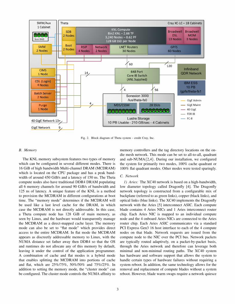
2) IB SAN: The installation of Theta had a key differencefrom prior ALCF system acquisitions. Unlike previous sys-tems, where users were migrated en masse from one stan-dalone compute and storage infrastructure to a new, replace-ment compute and storage infrastructure, it was necessary toprovide continuous parallel computing over the same storageinfrastructure used by both the Mira and Theta systems. Todo this, the existing Mira storage area network, based onInfiniBand (IB), was upgraded to provide a number of featuresspecific to the included Lustre storage system (see SectionIII-D), as well as to provide sufficient network capacity to fullyutilize the capabilities of the existing GPFS filesystems thatwere to be shared between both systems. Along the way, newchallenges were encountered when dealing with the limitationsimposed by physically massive optical networks.
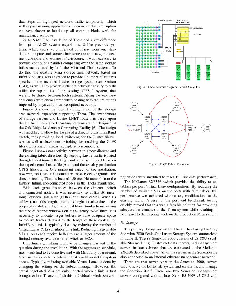
Figure 3 shows the logical configuration of the storagearea network expansion supporting Theta. The arrangementof storage servers and Lustre LNET routers is based uponthe Lustre Fine-Grained Routing implementation designed atthe Oak Ridge Leadership Computing Facility [6]. The designwas modified to allow for the use of a director-class InfiniBandswitch, thus providing local switching for the Lustre filesys-tem as well as backbone switching for reaching the GPFSfilesystems shared across multiple supercomputers.
Figure 4 shows connectivity between this new director andthe existing fabric directors. By keeping Lustre traffic isolatedthrough Fine-Grained Routing, contention is reduced betweenthe experimental Lustre filesystem and the existing productionGPFS filesystems. One important aspect of the installation,however, isn’t easily illustrated in these block diagrams: thedirector feeding Theta is located 150 feet (46 meters) from thefarthest InfiniBand-connected nodes in the Theta mainframe.
With such great distances between the director switchand connected nodes, it was necessary to utilize 50 meterlong Fourteen Data Rate (FDR) InfiniBand cables. When IBcables reach this length, problems begin to arise due to thepropagation delay of light in optical fiber. Similar to increasingthe size of receive windows on high-latency WAN links, it isnecessary to allocate larger buffers to have adequate spaceto receive frames delayed by the length of these cables. ForInfiniBand, this is typically done by reducing the number ofVirtual Lanes (VLs) available on a link. Reducing the availableVLs allows each receive buffer to use a larger amount of thelimited memory available on a switch or HCA.
Unfortunately, making fabric-wide changes was out of thequestion during the installation. With the aggressive schedule,most work had to be done live and with Mira fully operational.No disruptions could be tolerated that would impact filesystemaccess. Typically, reducing available Virtual Lanes is done bychanging the setting on the subnet manager. However, theactual negotiated VLs are only updated when a link is firstbrought online. To accomplish this, individual switch port con-
Fig. 3. Theta network diagram - credit Cray, Inc.
IS5600648pQDR
IS5600648pQDR
IS5600648pQDR
IS5600648pQDR
SX6536648pFDR
384 HCAs
384 HCAs
384 HCAs
384 HCAs
Theta HCAs
Blue: 108x QDR
Red: 36x QDR
Fig. 4. ALCF Fabric Overview
figurations were modified to reach full line-rate performance.The Mellanox SX6536 switch provides the ability to es-
tablish per-port Virtual Lane configurations. By reducing thenumber of available VLs on the ports with 50m cables, fullperformance was achieved without any modifications to theexisting fabric. A reset of the port and benchmark testingquickly proved that this was a feasible solution for providingadequate performance to the Theta system while resulting inno impact to the ongoing work on the production Mira system.
D. Storage
The primary storage system for Theta is built using the CraySonexion 3000 Scale-Out Lustre Storage System summarizedin Table II. Theta’s Sonexion 3000 consists of 28 SSU (Scal-able Storage Units), Lustre metadata servers, and managementservers in four cabinets that are connected to the MellanoxSX6536 described above. All of the servers in the Sonexion arealso connected to an internal ethernet management network.
There are two server types in the Sonexion 3000, serversused to serve the Lustre file system and servers used to managethe Sonexion itself. There are two Sonexion managementservers configured with an Intel Xeon E5-2609 v3 CPU with
4
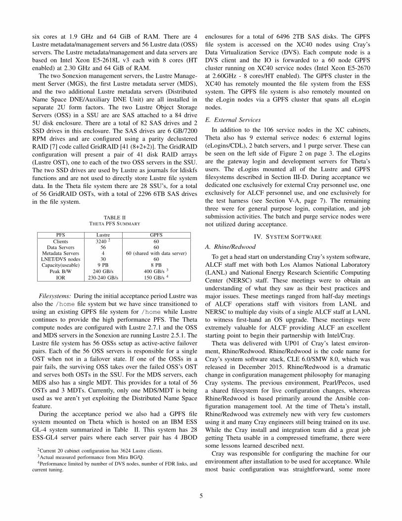
six cores at 1.9 GHz and 64 GiB of RAM. There are 4Lustre metadata/management servers and 56 Lustre data (OSS)servers. The Lustre metadata/management and data servers arebased on Intel Xeon E5-2618L v3 each with 8 cores (HTenabled) at 2.30 GHz and 64 GiB of RAM.
The two Sonexion management servers, the Lustre Manage-ment Server (MGS), the first Lustre metadata server (MDS),and the two additional Lustre metadata servers (DistributedName Space DNE/Auxiliary DNE Unit) are all installed inseparate 2U form factors. The two Lustre Object StorageServers (OSS) in a SSU are are SAS attached to a 84 drive5U disk enclosure. There are a total of 82 SAS drives and 2SSD drives in this enclosure. The SAS drives are 6 GB/7200RPM drives and are configured using a parity declusteredRAID [7] code called GridRAID [41 (8+2+2)]. The GridRAIDconfiguration will present a pair of 41 disk RAID arrays(Lustre OST), one to each of the two OSS servers in the SSU.The two SSD drives are used by Lustre as journals for ldiskfsfunctions and are not used to directly store Lustre file systemdata. In the Theta file system there are 28 SSU’s, for a totalof 56 GridRAID OSTs, with a total of 2296 6TB SAS drivesin the file system.
TABLE IITHETA PFS SUMMARY
PFS Lustre GPFSClients 3240 2 60
Data Servers 56 60Metadata Servers 4 60 (shared with data server)LNET/DVS nodes 30 60Capacity(useable) 9 PB 8 PB
Peak B/W 240 GB/s 400 GB/s 3
IOR 230-240 GB/s 150 GB/s 4
Filesystems: During the initial acceptance period Lustre wasalso the /home file system but we have since transitioned tousing an existing GPFS file system for /home while Lustrecontinues to provide the high performance PFS. The Thetacompute nodes are configured with Lustre 2.7.1 and the OSSand MDS servers in the Sonexion are running Lustre 2.5.1. TheLustre file system has 56 OSSs setup as active-active failoverpairs. Each of the 56 OSS servers is responsible for a singleOST when not in a failover state. If one of the OSSs in apair fails, the surviving OSS takes over the failed OSS’s OSTand serves both OSTs in the SSU. For the MDS servers, eachMDS also has a single MDT. This provides for a total of 56OSTs and 3 MDTs. Currently, only one MDS/MDT is beingused as we aren’t yet exploiting the Distributed Name Spacefeature.
During the acceptance period we also had a GPFS filesystem mounted on Theta which is hosted on an IBM ESSGL-4 system summarized in Table II. This system has 28ESS-GL4 server pairs where each server pair has 4 JBOD
2Current 20 cabinet configuration has 3624 Lustre clients.3Actual measured performance from Mira BG/Q.4Performance limited by number of DVS nodes, number of FDR links, and
current tuning.
enclosures for a total of 6496 2TB SAS disks. The GPFSfile system is accessed on the XC40 nodes using Cray’sData Virtualization Service (DVS). Each compute node is aDVS client and the IO is forwarded to a 60 node GPFScluster running on XC40 service nodes (Intel Xeon E5-2670at 2.60GHz - 8 cores/HT enabled). The GPFS cluster in theXC40 has remotely mounted the file system from the ESSsystem. The GPFS file system is also remotely mounted onthe eLogin nodes via a GPFS cluster that spans all eLoginnodes.
E. External Services
In addition to the 106 service nodes in the XC cabinets,Theta also has 9 external serivce nodes: 6 external logins(eLogins/CDL), 2 batch servers, and 1 purge server. These canbe seen on the left side of Figure 2 on page 3. The eLoginsare the gateway login and development servers for Theta’susers. The eLogins mounted all of the Lustre and GPFSfilesystems described in Section III-D. During acceptance wededicated one exclusively for external Cray personnel use, oneexclusively for ALCF personnel use, and one exclusively forthe test harness (see Section V-A, page 7). The remainingthree were for general purpose login, compilation, and jobsubmission activities. The batch and purge service nodes werenot utilized during acceptance.
IV. SYSTEM SOFTWARE
A. Rhine/Redwood
To get a head start on understanding Cray’s system software,ALCF staff met with both Los Alamos National Laboratory(LANL) and National Energy Research Scientific ComputingCenter (NERSC) staff. These meetings were to obtain anunderstanding of what they saw as their best practices andmajor issues. These meetings ranged from half-day meetingsof ALCF operations staff with visitors from LANL andNERSC to multiple day visits of a single ALCF staff at LANLto witness first-hand an OS upgrade. These meetings wereextremely valuable for ALCF providing ALCF an excellentstarting point to begin their partnership with Intel/Cray.
Theta was delivered with UP01 of Cray’s latest environ-ment, Rhine/Redwood. Rhine/Redwood is the code name forCray’s system software stack, CLE 6.0/SMW 8.0, which wasreleased in December 2015. Rhine/Redwood is a dramaticchange in configuration management philosophy for managingCray systems. The previous environment, Pearl/Pecos, useda shared filesystem for live configuration changes, whereasRhine/Redwood is based primarily around the Ansible con-figuration management tool. At the time of Theta’s install,Rhine/Redwood was extremely new with very few customersusing it and many Cray engineers still being trained on its use.While the Cray install and integration team did a great jobgetting Theta usable in a compressed timeframe, there weresome lessons learned described next.
Cray was responsible for configuring the machine for ourenvironment after installation to be used for acceptance. Whilemost basic configuration was straightforward, some more
5
complex or unique site configuration, like LDAP or interfacebonding, required more effort and coordination with ALCFstaff. The newness of Rhine/Redwood and the acceleratedacceptance schedule meant that there wasn’t much time todevelop best practices for configuration management in thenew Rhine/Redwood environment. However, since there wouldbe an unusually long period between acceptance and produc-tion, the emphasis was on getting a working configurationto meet our acceptance schedule. Even so, we did identifysome practices that would create a more stable acceptanceenvironment, aid in the post-acceptance knowledge transferfrom Cray to ALCF, and minimize the effort required to getthe machine into an operationally sustainable state.
Most importantly, it is critical to bring the various configu-ration management locations under revision control as earlyin the process as possible. Furthermore, it is important toestablish a simple policy on how revision control should beused with different configuration management locations andshare that with your Cray integration team ahead of time.Rhine/Redwood also includes a service called Simple Syncthat allows arbitrary files to be pushed out outside of Ansibleplaybooks or worksheets. While this may be tempting to geta configuration file out, it should be used sparingly, if at all.It is hard, if not nearly impossible, to track who put the filein Simple Sync and why, and trivial to break configurationdue to incorrect permissions or ownership. And while someconfiguration changes will most likely still get lost in the heatof the moment trying to get the system working for acceptance,these practices should help capture the majority of changesmade to get a working system after acceptance.
B. Cobalt
The ALCF uses the Cobalt scheduler and resource man-ager [8], which was originally developed at Argonne andmaintained by the ALCF. To maintain continuity for our usersand operations staff, Cobalt was ported to the Cray LinuxEnvironment. The port was done prior to the delivery of Thetautilizing a test system at Cray, with a goal of ensuring Cobaltwas ready as soon as the Theta system was booted afterinstall. Since Cobalt is the SRM on all ALCF productionsystems, which include IBM BlueGene/Q systems, generalLinux clusters, and previously on the IBM BlueGene/P, andBlueGene/L platforms, it was imperative that the ability tosupport the current ALCF science production environmentresources was maintained while extending the managementcapabilities of Cobalt.
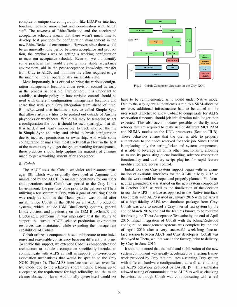
Cobalt utilizes a component-based architecture to maximizereuse and reasonable consistency between different platforms.To enable this support, we extended Cobalt’s component-basedarchitecture to include a component specifically intended tocommunicate with ALPS as well as support job-to-resource-association mechanisms that would be specific to the CrayXC40 (Figure 5). The ALPS interface was chosen over Na-tive mode due to the relatively short timeline leading up toacceptance, the requirement for high reliability, and the muchcleaner abstraction layer. Additionally aprun itself would not
Fig. 5. Cobalt Component Structure on the Cray XC40
have to be reimplemented as it would under Native mode.Due to the way aprun authenticates a run to a SRM-allocatedresource, additional infrastructure had to be added to theuser script launcher to allow Cobalt to compensate for ALPSreservation timeouts, should job initialization take longer thanexpected. This also accommodates possible on-the-fly nodereboots that are required to make use of different MCDRAMand NUMA modes on the KNL processors (Section III-B).These behaviors ensure that the user is able to properlyauthenticate to the nodes reserved for their job. Since Cobaltis replacing only the script forker and system components,it is able to leverage all of its other functionality, allowingus to use its preexisting queue handling, advance reservationfunctionality, and auxiliary script plug-ins for rapid featuremodification and access control.
Initial work on Cray system support began with an exam-ination of available interfaces for the XC40 in May 2015 sothat the work could be scoped and properly planned. Platform-neutral groundwork was started on the new system componentin October 2015, as well as the finalization of the decisionto use the ALPS interface as opposed to the Native interface.Direct tests with ALPS started in January 2016 with the arrivalof a high-fidelity ALPS test simulator package from Cray.Cobalt was able to control a Cray-internal test system by theend of March 2016, and had the features known to be requiredfor driving the Theta Acceptance Test suite by the end of April2016. Initial integration of Cobalt with the Rhine/Redwoodconfiguration management systems was complete by the endof April 2016 after a very successful week-long face-to-face session between ALCF and Cray developers. Cobalt wasdeployed to Theta, while it was in the factory, prior to delivery,by Cray in June 2016.
It should be noted that the build and stabilization of the newsystem component was greatly accelerated by a testing frame-work provided by Cray that emulates a running Cray systemwith different hardware configurations, as well as emulatingall ALPS behaviors provided by BASIL [9]. This simulatorallowed testing of communication to ALPS as well as checkingbehaviors as though Cobalt was communicating with a real
6
system, and provides rudimentary scaling checks. Addtionally,access to the small testbed system with early hardware (calledKachina) combined with a week-long face-to-face meeting,gave a great opportunity to test both Cobalt’s behavior againsta genuine system. Moreover, it provided a way to test andintegrate with the larger Rhine/Redwood management stackand its configuration management and provisioning system,and allowed us to leverage the experience that Cray hadin integrating other SRMs into the Rhine/Redwood softwarestack. The factory installation of Cobalt helped establishgreater confidence in Cobalt’s functionality on the early systemconfiguration at scale as well as giving Cray engineers someearly experience running their tests through Cobalt. This earlyintegration is considered essential to a rapid acceptance as wellas rapid spin-up of early science development efforts as thisnot only provided a robust batch scheduler on the system fromday one, but eliminated a major switch in running methodsbetween acceptance testing and user-facing work. Becauseall tasks were being run via Cobalt or within a dedicatedreservation within Cobalt, determining utilization and machineload was made much easier for acceptance testing. Thisalso allowed us to leverage an Argonne developed automatedtesting framework that uses Cobalt for scheduling, managing,and reporting outcomes of tests (Section V-A).
There were a few differences between the Cray XC40 andthe Rhine/Redwood software stack that required extra care toaccommodate when compared to other systems that Cobaltsupports. First is the mechanism that ALPS uses to commu-nicate with SRMs in a language agnostic manner. BASIL isa process that is forked with custom XML-formatted requestssent to BASIL’s stdin, with custom XML-responses returnedvia BASIL’s stdout [10]. Most of Cobalt’s processes are multi-threaded for responsiveness during IO-bound and remote-callwork. Utilizing a POSIX fork once threads are running createsa near-certainty of deadlocks due to parent locks being setby the newly forked child process. While atfork() may beused to force the release of these locks, numerous libraries,including glibc, do not properly utilize this function. To workaround this limitation, Cobalt has a set of single-threadedcomponents known as “forkers” which are single-threadedshepherd daemons who actually handle forking and trackingall spawned processes, including prescripts, postscripts, anduser jobs. BASIL is invoked via the system script forker forevery ALPS instruction so that it may be run in a safe manner.
Additionally, we encountered an issue with “disabled” nodesand their return to service. When a Cray XC40 system isbooted, nodes in distress may be put into a “disabled” state.This prevents the nodes from interfering with the boot with theside effect of the existence of these nodes being unreportedby most of the Cray software stack. This causes the nodeto “disappear” from Cobalt on restart as the node no longerappears in the machine’s inventory. When the node is laterrepaired and swapped in, a fairly heavyweight request forsystem inventory occurs to get full data on the node. Initially,this caused a hang in Cobalt as the BASIL call processingwould ultimately time out, in addition to the node having to
be added on-the-fly back into Cobalt’s view of the machine.This hang was corrected prior to acceptance, though the nodedisappearance has other problems when constructing resourcereservations for the full system for maintenance as the nodeeither disappears across the restart, or the node cannot bereserved due to its invisibility to Cobalt.
Cobalt’s job prescript and postscript was used to provide amechanism for on-the fly memory mode control via CAPMC.One script checks and determines if a memory mode switchis needed and a second postscript reverts the nodes backto a default memory configuration. These were tested onKachina. Due to the long reboot times as well as early rebootreliability concerns, this functionality was not used during theacceptance test period. A set of queues were used for eachMCDRAM and NUMA mode configuration under test. Userscould queue up their jobs for their requested memory modes atany time, and the the jobs would run when there were sufficientnodes operating in the desired memory mode attached to thatqueue. This allowed for tests of multiple configurations with amoderate amount of administrative overhead. Work is ongoingas to how to best automate these switches, particularly withrespect to workloads running at 20% of the machine or largerin production, and minimizing the switch cost.
Management of user interactive shell jobs proved challeng-ing in the eLogin environment. Due to the use of wrappersthat ssh and execute commands on a net node in the eLoginenvironment, there were problems in aprun authentication toa batch-mode ALPS reservation from the eLogins. This wascorrected by causing Cobalt’s qsub command to first log theuser into a MoM internal service node, invoking a sub-instanceof qsub from there, and then allowing the interactive mode runto proceed. This interactive mode provides the ability for usersto run aprun from their shell, but it does not place the user onthe compute nodes, unlike cluster compatibility mode. This isvery similar to both the restrictions and is consistent with themethod of running that exists in the BlueGene environment.
Acceptance was run with an early version of Cobalt and wasrun using the ALPS first-fit allocator. Draining of resourcesfor larger jobs was done either opportunistically by increasingthe score of jobs or utilizing holds to ensure that large jobsran right after machine maintenance periods, or by usingCobalt’s advance-reservation mechanism to provide a similarfunction. Immediately after acceptance a version was deployedthat provided resource draining with backfill behavior toavoid starving large nodecount jobs. This has provided goodthroughput as well as good utilization of Theta for earlyscience purposes.
V. EARLY RESULTS
A. Acceptance
Theta was installed in early July 2016 with an acceleratedtimeline. The system completed testing and was accepted onSeptember 30, 2016. The testing stage consisted of 4 weeksof acceptance testing and a two week period for running EarlyScience [11] projects. We had approximately six weeks toprepare and validate our test setup prior to beginning the
7
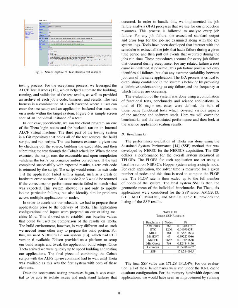
Fig. 6. Screen capture of Test Harness test instance
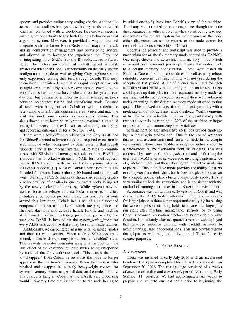
testing process. For the acceptance process, we leveraged theALCF Test Harness [12], which helped automate the building,running, and validation of the test results, as well as providedan archive of each job’s code, binaries, and results. The testharness is a combination of a web backend where a user canenter the test setup and an application backend that executeson a node within the target system. Figure 6 is sample screenshot of an individual instance of a test.
In our case, specifically, we ran the client program on oneof the Theta login nodes and the backend ran on an internalALCF virtual machine. The third part of the testing systemis a Git repository that holds all of the test sources, the buildscripts, and run scripts. The test harness executes a given testby checking out the source, building the executable, and thensubmitting the test through the Cobalt scheduler. When the testexecutes, the script runs the executable and upon completionvalidates the test’s performance and/or correctness. If the testcompleted successfully with expected results, a zero exit codeis returned by the script. The script would return an exit code1 if the application failed with a signal, such as a crash orhardware error occurred. An exit code 2 or 3 would be returnedif the correctness or performance metric failed to match whatwas expected. This system allowed us not only to rapidlyisolate particular failures, but also identify similar problemsacross multiple applications or nodes.
In order to accelerate our schedule, we had to prepare theseapplications prior to the delivery of Theta. The applicationconfigurations and inputs were prepared on our existing ma-chine Mira. This allowed us to establish our baseline valuesthat could be used for comparison of the results on Theta.The build environment, however, is very different and as suchwe needed some other way to prepare the build portion. Forthis, we used NERSC’s Edison system [13], which had CLEversion 6 available. Edison provided us a platform to setupour build scripts and tweak the application build setups. OnceTheta arrived we were quickly up to speed building and testingour applications. The final piece of combining the Cobaltscripts with the ALPS aprun command had to wait until Thetawas available as this was the first system with both of theseelements.
Once the acceptance testing processes began, it was essen-tial to be able to isolate issues and understand failures that
occurred. In order to handle this, we implemented the jobfailure analysis (JFA) processes that we use for our productionresources. This process is followed to analyze every jobfailure. For any job failure, the associated standard outputand error logs for the job are examined along with the keysystem logs. Tools have been developed that interact with thescheduler to extract all the jobs that had a failure during a giventime period and then pull out events that occurred during thejobs run time. These procedures account for every job failurethat occurred during acceptance. For any related failure a rootcause is identified, if possible. This job failure process not onlyidentifies all failures, but also any extreme variability betweenjob runs of the same application. The JFA process is critical toestablishing confidence in the system’s behavior by providinga definitive understanding to any failure and the frequency atwhich failures are occurring.
The evaluation of the system was done using a combinationof functional tests, benchmarks and science applications. Atotal of 170 major test cases were defined, the bulk ofthose being functional tests which covered various aspectsof the machine and software stack. Here we will cover thebenchmarks and the associated performance and then look atthe science application scaling results.
B. Benchmarks
The performance evaluation of Theta was done using theSustained System Performance [14] (SSP) method that wasdeveloped by NERSC for the NERSC8 acquisition. The SSPdefines a performance for the overall system measured inTFLOPs. The FLOPS for each application are set using abaseline run on NERSC’s Hopper system using a single node.For each application, the solver time is measured for a givennumber of nodes and this time is used to compute the FLOPrate. The FLOP rate is then scaled up to the full numberof nodes of the system. The final system SSP is then thegeometric mean of the individual benchmarks. For Theta, sixapplications were considered for the SSP score: AMG2013,GTC, MILC, MiniDFT, and MiniFE. Table III provides thelisting of the SSP results.
TABLE IIITHETA SSP RESULTS
Benchmark Nodes PiAMG2013 768 0.012061731
GTC 1200 0.049908531MILC 384 0.056735604
MiniDFT 47 0.392259086MiniFE 2662 0.013050658
MiniGhost 768 0.124849456Geomean - 0.052865462
SSP 171.2840965
The final SSP value was 171.28 TFLOP/s. For our evalua-tion, all of these benchmarks were run under the KNL cachequadrant configuration. For the memory bandwidth dependentapplications, we would have seen an improvement by running
8
the test case under the flat quadrant mode; however, we electedto run all of our applications under a consistent mode.
In addition to the SSP benchmarks, we ran the SandiaMPI Benchmark (SMB) message rate, STREAM Triad, andI/O benchmarks. The SMB message rate benchmark measuresmessage rates for a given message size between pairs of endpoints using 8 nodes. Table IV shows the results for 8-byteand 1024-byte messages using the pair-wise method.
TABLE IVTHETA SMB RESULTS
Message Size Message Rate8 byte 16.1 mmps
1024 byte 7.3 mmps
The STREAM [15] benchmark measures memory band-width for different workloads although we just examined theTriad result. Given the different memory and NUMA modeconfigurations the KNL offers, we ran this benchmark underthe different configurations although the majority of all othertesting was done using cache mode. Each test was done using asingle node with 64 MPI processes per node each with a singlethread. Table V show the results for the different memorymodes with the cluster mode being set to quadrant for allcases. The size reported in Table V is the total size reportedby the STREAM benchmark for all of the arrays used.
TABLE VTHETA STREAM RESULTS
Mode Size (GiB) BW (GiB/s)Flat 7.8 447.9
Cache 7.8 308.2Hybrid (50/50) 7.8 442.5Hybrid (50/50) 97.6 57.9
The I/O performance was evaluated using two I/O bench-marks, IOR and mdtest. The IOR [16] benchmark was usedto evaluate the I/O bandwidth of the Lustre file system usingan optimal workload to get the maximum performance.
TABLE VITHETA IOR RESULTS
Command Nodes Write BW Read BW-a POSIX -e -g -[w|r]-t 64M -b 12g -F -k -E-o <file>
1792 247 GB/s 235 GB/s
The mdtest [17] application evaluated metadata rates interms of operations per second for different types of opera-tions. The mdtest application run across the entire machinetesting the Lustre volume. The Lustre volume was configuredwith no DNE support, so this test is measuring the rate of asingle MDS/MDT. Mdtest is run with the following arguments:-i 1 -d /lus/theta-fs0/... -n 10.
TABLE VIITHETA MDTEST RESULTS
Operation Rate (ops/s)Directory creation 24129.947Directory stat 133717.879Directory removal 11199.838File creation 43459.599File stat 130676.940File read 93707.416File removal 29923.935Tree creation 194.406Tree removal 42.541
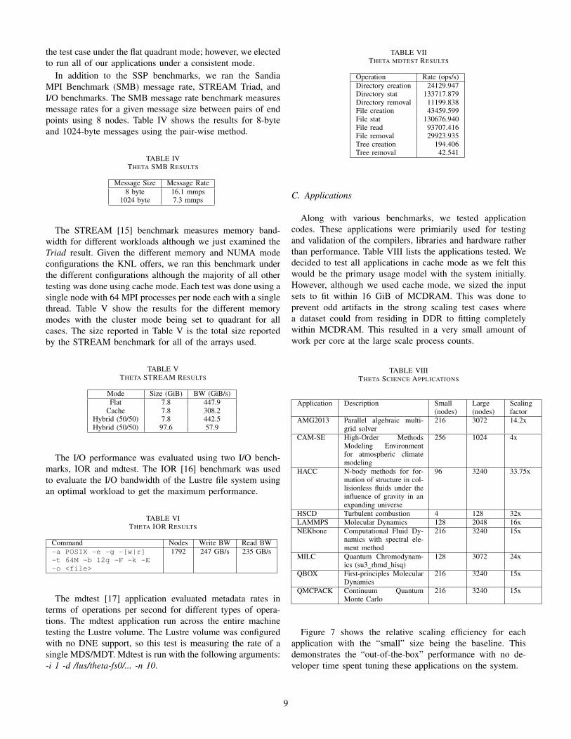
C. Applications
Along with various benchmarks, we tested applicationcodes. These applications were primiarily used for testingand validation of the compilers, libraries and hardware ratherthan performance. Table VIII lists the applications tested. Wedecided to test all applications in cache mode as we felt thiswould be the primary usage model with the system initially.However, although we used cache mode, we sized the inputsets to fit within 16 GiB of MCDRAM. This was done toprevent odd artifacts in the strong scaling test cases wherea dataset could from residing in DDR to fitting completelywithin MCDRAM. This resulted in a very small amount ofwork per core at the large scale process counts.
TABLE VIIITHETA SCIENCE APPLICATIONS
Application Description Small(nodes)
Large(nodes)
Scalingfactor
AMG2013 Parallel algebraic multi-grid solver
216 3072 14.2x
CAM-SE High-Order MethodsModeling Environmentfor atmospheric climatemodeling
256 1024 4x
HACC N-body methods for for-mation of structure in col-lisionless fluids under theinfluence of gravity in anexpanding universe
96 3240 33.75x
HSCD Turbulent combustion 4 128 32xLAMMPS Molecular Dynamics 128 2048 16xNEKbone Computational Fluid Dy-
namics with spectral ele-ment method
216 3240 15x
MILC Quantum Chromodynam-ics (su3 rhmd hisq)
128 3072 24x
QBOX First-principles MolecularDynamics
216 3240 15x
QMCPACK Continuum QuantumMonte Carlo
216 3240 15x
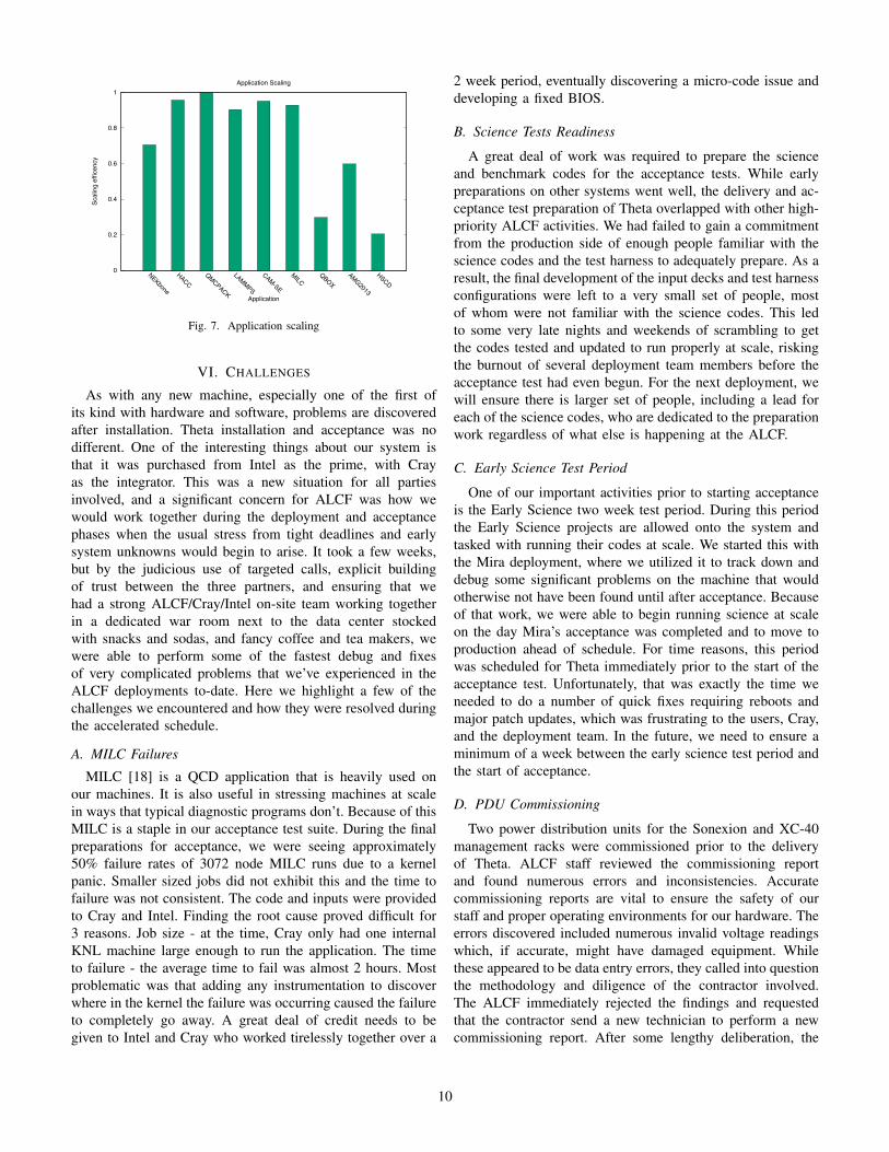
Figure 7 shows the relative scaling efficiency for eachapplication with the “small” size being the baseline. Thisdemonstrates the “out-of-the-box” performance with no de-veloper time spent tuning these applications on the system.
9
0
0.2
0.4
0.6
0.8
1
NEKbone
HACCQMCPACK
LAMMPS
CAM-SE
MILCQBOX
AMG2013
HSCD
Scal
ing
effic
ency
Application
Application Scaling
Fig. 7. Application scaling
VI. CHALLENGES
As with any new machine, especially one of the first ofits kind with hardware and software, problems are discoveredafter installation. Theta installation and acceptance was nodifferent. One of the interesting things about our system isthat it was purchased from Intel as the prime, with Crayas the integrator. This was a new situation for all partiesinvolved, and a significant concern for ALCF was how wewould work together during the deployment and acceptancephases when the usual stress from tight deadlines and earlysystem unknowns would begin to arise. It took a few weeks,but by the judicious use of targeted calls, explicit buildingof trust between the three partners, and ensuring that wehad a strong ALCF/Cray/Intel on-site team working togetherin a dedicated war room next to the data center stockedwith snacks and sodas, and fancy coffee and tea makers, wewere able to perform some of the fastest debug and fixesof very complicated problems that we’ve experienced in theALCF deployments to-date. Here we highlight a few of thechallenges we encountered and how they were resolved duringthe accelerated schedule.
A. MILC Failures
MILC [18] is a QCD application that is heavily used onour machines. It is also useful in stressing machines at scalein ways that typical diagnostic programs don’t. Because of thisMILC is a staple in our acceptance test suite. During the finalpreparations for acceptance, we were seeing approximately50% failure rates of 3072 node MILC runs due to a kernelpanic. Smaller sized jobs did not exhibit this and the time tofailure was not consistent. The code and inputs were providedto Cray and Intel. Finding the root cause proved difficult for3 reasons. Job size - at the time, Cray only had one internalKNL machine large enough to run the application. The timeto failure - the average time to fail was almost 2 hours. Mostproblematic was that adding any instrumentation to discoverwhere in the kernel the failure was occurring caused the failureto completely go away. A great deal of credit needs to begiven to Intel and Cray who worked tirelessly together over a
2 week period, eventually discovering a micro-code issue anddeveloping a fixed BIOS.
B. Science Tests Readiness
A great deal of work was required to prepare the scienceand benchmark codes for the acceptance tests. While earlypreparations on other systems went well, the delivery and ac-ceptance test preparation of Theta overlapped with other high-priority ALCF activities. We had failed to gain a commitmentfrom the production side of enough people familiar with thescience codes and the test harness to adequately prepare. As aresult, the final development of the input decks and test harnessconfigurations were left to a very small set of people, mostof whom were not familiar with the science codes. This ledto some very late nights and weekends of scrambling to getthe codes tested and updated to run properly at scale, riskingthe burnout of several deployment team members before theacceptance test had even begun. For the next deployment, wewill ensure there is larger set of people, including a lead foreach of the science codes, who are dedicated to the preparationwork regardless of what else is happening at the ALCF.
C. Early Science Test Period
One of our important activities prior to starting acceptanceis the Early Science two week test period. During this periodthe Early Science projects are allowed onto the system andtasked with running their codes at scale. We started this withthe Mira deployment, where we utilized it to track down anddebug some significant problems on the machine that wouldotherwise not have been found until after acceptance. Becauseof that work, we were able to begin running science at scaleon the day Mira’s acceptance was completed and to move toproduction ahead of schedule. For time reasons, this periodwas scheduled for Theta immediately prior to the start of theacceptance test. Unfortunately, that was exactly the time weneeded to do a number of quick fixes requiring reboots andmajor patch updates, which was frustrating to the users, Cray,and the deployment team. In the future, we need to ensure aminimum of a week between the early science test period andthe start of acceptance.
D. PDU Commissioning
Two power distribution units for the Sonexion and XC-40management racks were commissioned prior to the deliveryof Theta. ALCF staff reviewed the commissioning reportand found numerous errors and inconsistencies. Accuratecommissioning reports are vital to ensure the safety of ourstaff and proper operating environments for our hardware. Theerrors discovered included numerous invalid voltage readingswhich, if accurate, might have damaged equipment. Whilethese appeared to be data entry errors, they called into questionthe methodology and diligence of the contractor involved.The ALCF immediately rejected the findings and requestedthat the contractor send a new technician to perform a newcommissioning report. After some lengthy deliberation, the
10
contractor remedied the situation, performanced a new com-missioning, and produced a valid report. One lesson-learnedfrom this experience is that such work by contractors oughtto be observed by ALCF subject-matter experts. This wouldperhaps help to reduce the schedule impact of any discoveredissues.
E. Flat-Quad Performance
Early in the preparation phase we compiled and ran all ofthe SSP tests to ensure that they completed and met theiranticipated performance targets. The preliminary results wereinline with results achieved at the factory. However, once thefunctional and performance phase (ATP-FP) had begun, thetests meant to be run in the flat-quad memory mode wereperforming about twice as slow as they should. Working withCray and Intel we were able to determine that a specificpatch set that had been applied during the integration phaseto fix an unrelated issue was the cause. Normally the fixwould be simple - back out the problematic patch set andrerun. Unfortunately there were multiple challenges. First,because ATP-FP had officially started, no changes to softwareor configuration were allowed. If any needed to be made, ATP-FP would have to be restarted with all already completed jobshaving to be rerun. These flat-quad jobs were run at the end ofATP-FP so this would have added at least 3 more days to theschedule to rerun everything again. Second, the problematicpatch set was necessary to fix a blocking issue so a new patchneeded to be developed to fix the performance issue. Crayquickly developed a patch and tunings for these benchmarksto run fast enough under the cache-quad memory mode toachieve our SSP targets. Once ATP-FP was completed, webriefly booted with the patch to verify that the problem wassolved and then returned the machine to the official acceptanceconfiguration. These performance tests have been added to theALCF regression test suite used to exercise the system aftereach major installation.
VII. CONCLUSION
ALCF received, installed, and accepted a Cray XC40 namedTheta in just over three months from late June 2016 toSeptember 2016. ALCF did a significant amount of prepratorywork from facility enhancments (busduct, increased weightcapacity, water loop, and even cable trays) to designing andinstalling the IB SAN for the Sonexion 3000, and a GPFSfilesystem to porting the Cobalt scheduler that was ready forTheta day one. This prepratory work made it possible tobegin testing benchmarks and applications soon after poweron. There were several issues that were identified, some thatrequired a lot of expert work by ALCF, Intel, and Cray (duringand after acceptance.) Regardless, acceptance was started just2 months after delivery and after a 4 week acceptance period,Theta was accepted.
ACKNOWLEDGMENT
This research used resources of the Argonne LeadershipComputing Facility, which is a DOE Office of Science UserFacility supported under Contract DE-AC02-06CH11357.
We would like to recognize all the ALCF staff who con-tributed on the rapid integration efforts and acceptance testing.
We would like to thank the following Cray personnel fortheir extraordinary efforts: Joe Glenski, Richard Walsh, ClarkSnyder, Jon Bouvet, Mike Solari.
We would like to thank Jacob Wood and the Intel systemdebug team for their extraordinary efforts.
REFERENCES
[1] [Online]. Available: http://www.alcf.anl.gov[2] [Online]. Available: http://www.doeleadershipcomputing.org[3] A. Sodani, “Knights Landing: 2nd generation Intel Xeon Phi processor.”
Hot Chips ’15, 2015.[4] J. Kim, W. J. Dally, S. Scott, and D. Abts, “Technology-driven,
highly-scalable dragonfly topology,” in Proceedings of the 35th AnnualInternational Symposium on Computer Architecture, ser. ISCA ’08.Washington, DC, USA: IEEE Computer Society, 2008, pp. 77–88.[Online]. Available: http://dx.doi.org/10.1109/ISCA.2008.19
[5] B. Alverson, E. Froese, L. Kaplan, and D. Roweth, “Cray XC seriesnetwork.” [Online]. Available: http://www.cray.com/sites/default/files/resources/CrayXCNetwork.pdf
[6] D. A. Dillow, G. M. Shipman, S. Oral, and Z. Zhang, “I/O congestionavoidance via routing and object placement,” in Proceedings of CrayUser Group Conference (CUG 2011), 2011.
[7] M. Holland and G. A. Gibson, Parity declustering for continuousoperation in redundant disk arrays. ACM, 1992, vol. 27, no. 9.
[8] COBALT: Component-based lightweight toolkit. [Online]. Available:http://trac.mcs.anl.gov/projects/cobalt
[9] basil(7) Miscellaneous Information Manual, April 2016.[10] apbasil(1) General Commands Manual, June 2012.[11] “ALCF Theta Early Science Program.” [Online]. Available: https:
//www.alcf.anl.gov/early-science-theta-cfp[12] E. Pershey, “Automated testing of supercom-
puters.” [Online]. Available: https://www.alcf.anl.gov/files/AutomatedTestingofSupercomputers\ 0.pdf
[13] “Nersc edison system.” [Online]. Available: http://www.nersc.gov/users/computational-systems/edison/
[14] “Sustained system performance.” [Online]. Available: http://www.nersc.gov/users/computational-systems/cori/nersc-8-procurement/trinity-nersc-8-rfp/nersc-8-trinity-benchmarks/ssp/
[15] J. D. McCalpin, “Memory bandwidth and machine balance in currenthigh performance computers,” IEEE Computer Society Technical Com-mittee on Computer Architecture (TCCA) Newsletter, pp. 19–25, Dec.1995.
[16] “Parallel filesystem I/O benchmark.” [Online]. Available: https://github.com/LLNL/ior
[17] “mdtest.” [Online]. Available: https://github.com/MDTEST-LANL/mdtest
[18] “MIMD Lattice Computation (MILC) Collaboration.” [Online].Available: http://physics.indiana.edu/∼sg/milc.html
11