thetechnicalchallengesofthe...
TRANSCRIPT

rsta.royalsocietypublishing.org
ReviewCite this article: Collier P. 2015 The technicalchallenges of the Large Hadron Collider. Phil.Trans. R. Soc. A 373: 20140044.http://dx.doi.org/10.1098/rsta.2014.0044
One contribution of 12 to a Discussion MeetingIssue ‘Before, behind and beyond thediscovery of the Higgs boson’.
Subject Areas:high energy physics
Keywords:Large Hadron Collider
Author for correspondence:Paul Colliere-mail: [email protected]
The technical challenges of theLarge Hadron ColliderPaul Collier
CERN, Geneva, Switzerland
The Large Hadron Collider (LHC) is a 27 kmcircumference hadron collider, built at CERN toexplore the energy frontier of particle physics.Approved in 1994, it was commissioned and beganoperation for data taking in 2009. The design andconstruction of the LHC presented many design,engineering and logistical challenges which involvedpushing a number of technologies well beyond theirlevel at the time. Since the start-up of the machine,there has been a very successful 3-year run withan impressive amount of data delivered to the LHCexperiments. With an increasingly large stored energyin the beam, the operation of the machine itselfpresented many challenges and some of these will bediscussed. Finally, the planning for the next 20 yearshas been outlined with progressive upgrades of themachine, first to nominal energy, then to progressivelyhigher collision rates. At each stage the technicalchallenges are illustrated with a few examples.
1. IntroductionDuring the early 1980s, the high-energy physics comm-unity was already beginning to look at what would beneeded as a future facility at the energy frontier. AtCERN, the construction of the Large Electron PositronCollider (LEP) had just been approved and in the USA,the Tevatron had just begun operation with collisions ofhadrons at around 2 TeV in the centre of mass (CM). Theconsensus was that the next machine needed to push intoa new energy domain to explore the region between theLEP mass limit and 1 TeV. For this purpose, a hadron–hadron collider with the highest possible primary beamenergy and collision rate was considered to be ideallysuited. The requirement of high primary beam energycomes from the fact that hadrons are composite particlesand the energy is shared between the quarks and gluons.The high collision rate is needed to search for the veryrare events that would be associated with new particles.These two factors therefore became the main designchallenges for the new machine.
2014 The Author(s) Published by the Royal Society. All rights reserved.
on September 5, 2018http://rsta.royalsocietypublishing.org/Downloaded from
2
rsta.royalsocietypublishing.orgPhil.Trans.R.Soc.A373:20140044
.........................................................
In the USA, plans were drawn up for the superconducting super collider (SSC) [1]. This wasdesigned to be a machine with a CM energy of 40 TeV and would be constructed on a ‘green-field’site. An alternative design was developed at CERN to make use of the existing infrastructure ofthe laboratory, including the 27 km LEP tunnel, then under construction [2]. This machine becamethe Large Hadron Collider (LHC). Eventually, cost issues led to the cancellation of the SSC projectand the relatively cheaper LHC machine was approved for construction in the mid-1990s.
2. Design challengesIn a circular accelerator dipole, magnets are used to bend the trajectory of the particles around thecircumference of the machine. There is a relatively simple relationship between the energy of thebeam (in GeV), the dipole field needed (in tesla) and the bending radius of the ring (in metre)
E ≈ 0.3.B.R. (2.1)
In the LHC case, R was fixed at 2804 m by the existing tunnel built for LEP. To reach a beam energyof 7 TeV (allowing 14 TeV CM collisions), a dipole field of 8.33 T would, therefore, be required witha total of 17.6 km of active dipole field. In addition, given the constraints of the existing tunnelcross section, a two-in-one dipole construction would be needed. The collision energy availablein LHC represents a factor 7 increase over previous machines.
In a collider, the event rate for producing a particular type of event is the product of thecollision rate (or luminosity) and the cross section for that event type. The cross section isexpressed in units of area, called barns (1 barn = 10−24 cm2). The luminosity, L, is given by theequation (2.2) [3]
L = N2b nb frevγ
4πεnβ∗ F, (2.2)
where the beam takes the form of nb bunches each having Nb particles making frev revolutions ofthe accelerator per second. γ is the relativistic factor and εnβ∗ is related to the beam size at theinteraction point. The factor F is related to the geometry of the collision, with a value of 1 for headon collisions and reduces as the crossing angle increases
F = 1√
1 + Θ2; Θ ≡ θcσz
2σx. (2.3)
Here, θc is the crossing angle, σx is the beam size in the crossing angle plane and σz is thelongitudinal bunch length.
From equation (2.2), it can be seen that to achieve high luminosity, one has to make lots of highpopulation bunches collide at high frequency in locations where the beam optics provides as lowvalues of the beam size as possible. Optimization of these parameters is an important part of thedesign process. The parameter set for the LHC promised a luminosity of 10+34 cm−2 s−1, whichrepresents a factor 100 increase over previous equivalent colliders.
3. Engineering challengesRealizing a paper design of a large facility like the LHC presents engineering challenges acrossvirtually every engineering discipline. In this paper, I consider only two: magnets and cryogenics.More details on the overall design of the machine as well as the main technical systems can befound in [4–6].
(a) MagnetsIn an electromagnet used in particle accelerators, a current flowing through a set of coils generatesthe field. In a normal-conducting electromagnet, this field is dominated (and limited) by themagnetization of an iron yoke through which the coils pass. The quality of the field in thebeam aperture is determined by the exact geometry of the yoke close to the beam pipe. This
on September 5, 2018http://rsta.royalsocietypublishing.org/Downloaded from
3
rsta.royalsocietypublishing.orgPhil.Trans.R.Soc.A373:20140044
.........................................................
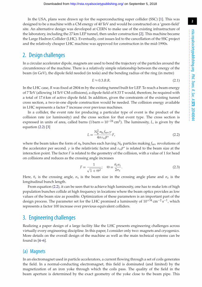
alignment targetmain quadrupole bus-barsheat exchanger pipesuperinsulationsuperconducting coilsbeam pipeshrinking cylinder/HE-I VESSELiron yokevacuum vesselthermal shieldauxiliary bus-barsaustenidic steel collarsbeam screeniron insertinstrumentation wiresfiller piecedipole bus-barssupport post
Figure 1. The LHC dipole cross section.
(a) (b)
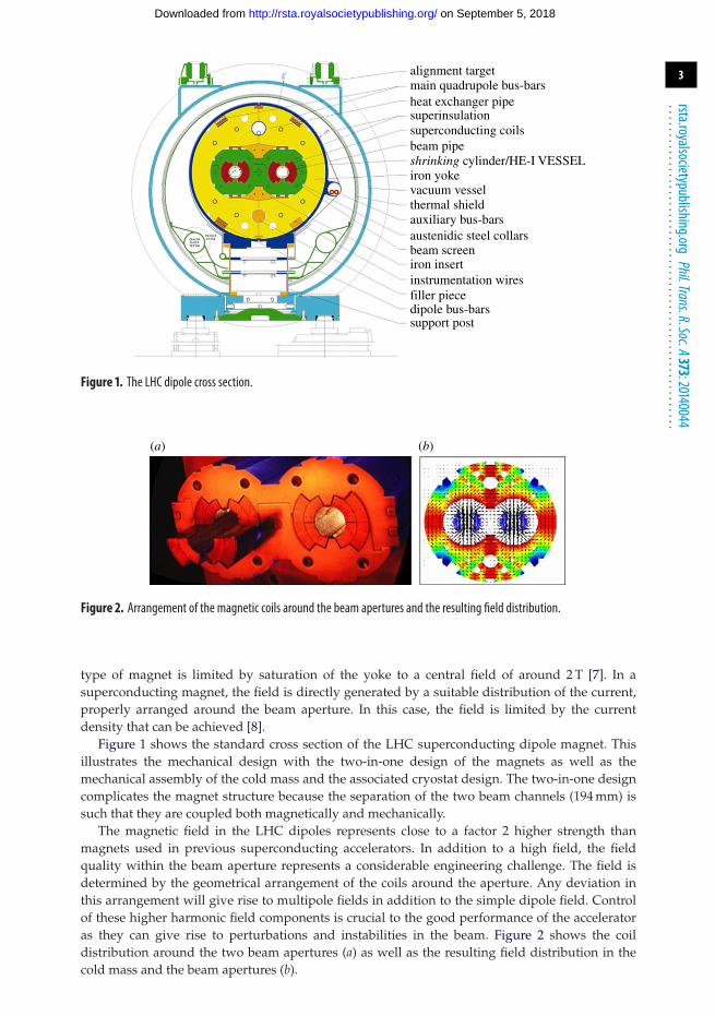
Figure 2. Arrangement of the magnetic coils around the beam apertures and the resulting field distribution.
type of magnet is limited by saturation of the yoke to a central field of around 2 T [7]. In asuperconducting magnet, the field is directly generated by a suitable distribution of the current,properly arranged around the beam aperture. In this case, the field is limited by the currentdensity that can be achieved [8].
Figure 1 shows the standard cross section of the LHC superconducting dipole magnet. Thisillustrates the mechanical design with the two-in-one design of the magnets as well as themechanical assembly of the cold mass and the associated cryostat design. The two-in-one designcomplicates the magnet structure because the separation of the two beam channels (194 mm) issuch that they are coupled both magnetically and mechanically.
The magnetic field in the LHC dipoles represents close to a factor 2 higher strength thanmagnets used in previous superconducting accelerators. In addition to a high field, the fieldquality within the beam aperture represents a considerable engineering challenge. The field isdetermined by the geometrical arrangement of the coils around the aperture. Any deviation inthis arrangement will give rise to multipole fields in addition to the simple dipole field. Controlof these higher harmonic field components is crucial to the good performance of the acceleratoras they can give rise to perturbations and instabilities in the beam. Figure 2 shows the coildistribution around the two beam apertures (a) as well as the resulting field distribution in thecold mass and the beam apertures (b).
on September 5, 2018http://rsta.royalsocietypublishing.org/Downloaded from

4
rsta.royalsocietypublishing.orgPhil.Trans.R.Soc.A373:20140044
.........................................................
P5
8 × 18 kW at 4.5 K
1800 sc magnets
24 km and 20 kW at 1.8 K
37 000 t at 1.9 K
130 t He inventory
P6
P7
P8
-cryogenic plantP1
P2
P3
P4
1.8
Figure 3. The layout of the cryogenic plants around the LHC.
Each individual dipole has a magnetic length of 14.4 m when cold, an overall length of 16 mand a weight of approximately 36 000 kg when mounted into its vacuum cryostat. In order to reachthe very high current density, the temperature of the magnets must be cooled with superfluidhelium (He II) and operated at a temperature of 1.9 K. Below 2.17 K (the lambda point), helium issuperfluid with the following characteristics:
— very low viscosity approximately 100 times less than water at normal boiling point;— very high specific heat capacity approximately 100 000 times higher than the cable
conductor in the magnet by unit mass; and— very high thermal conductivity, approximately 3000 times higher than pure copper.
These characteristics have been fully exploited in the magnet design and in the cooling scheme toenable the dipole field to reach close to 9 T [9].
(b) CryogenicsThe majority of the magnets in the LHC are superconducting and must be cryogenically cooled.In the arcs, the magnet cold mass is immersed in a pressurized bath of superfluid helium ata pressure of 1.3 bar and operated at a temperature of 1.9 K. A few magnets in the straightsections of the machine require lower fields and are therefore operated at 4.5 K. In total, theLHC cryogenic system has to cool approximately 37 000 t of material to 1.9 K. This requires a totalhelium inventory of approximately 130 t. The production and distribution of such a large amountof He II at pressures above atmospheric pressure is therefore a significant engineering challengefor the system.
The secret lies in the use of a two-stage cooling system [10]. The primary cooling plants comesfrom eight, 4.5 K warm compressor plants, each capable of producing 18 kW of cooling capacity at4.5 K. Most of the liquid helium produced is then distributed around the eight cryogenic sectorsof the machine and used to fill the magnets in a static pressurized bath. Figure 3 shows the layoutof the cryogenic plants around the LHC.
The second cooling stage uses cold compressors installed in each underground location. Theseproduce He II by reduction of the pressure in the circuit to 15 mbar. The low-pressure saturatedHe II is then transported around the sectors of the machine and used to feed a low-pressure heatexchanger tube, which runs through each magnet. This line is situated at the top of the magnetcold mass in figure 1. The exchange of heat between this line and the main helium bath allowscooling of the whole cold mass to 1.9 K. The arrangement is shown schematically in figure 4.
The resulting cryogenic system is very large and complex. Careful control of the coolingprocess is needed, especially during cool down and warm up of the sectors to avoid large
on September 5, 2018http://rsta.royalsocietypublishing.org/Downloaded from

5
rsta.royalsocietypublishing.orgPhil.Trans.R.Soc.A373:20140044
.........................................................
saturated He II, flowingpressurized He II, static
heat exchanger tube
sc bus bar connection
helium vessel
magnet
Figure 4. LHC magnet string cooling scheme.
temperature differences and hence mechanical stress. A complete cool down of a sector fromroom temperature to 1.9 K can be achieved in around three weeks. In addition to the static lossescoming from the heat loss to the environment, the system must cope with dynamic losses fromthe powering of the magnets and from beam induced heating. Finally, the reliability of the systemas a whole must be very high as any breakdown can lead to long recovery times due to the largethermal inertia of the system. In practice reliability in excess of 95% has been achieved duringroutine operation of the LHC.
4. Logistical challengesThe operation of the LEP machine was terminated in November 2000. The first job was to removethe LEP machine and much of the existing infrastructure in order to prepare the tunnel for theLHC. The LEP dismantling was in itself a huge project with some 35 000 t of material to beremoved. Large sections of the tunnel had to be stripped down almost to the bare concrete inorder to enable the civil engineering teams to move in. The most critical two-thirds of the tunnelcircumference were emptied in a very intense three-month period [11].
While it is true that the tunnel already existed, in many areas the underground structuresneeded to be adapted to the needs of the LHC and major civil engineering works undertaken.The major areas included the construction of the ATLAS and CMS caverns, the extraction linesfor the beam dumps and the boring of two, 3 km transfer lines between the LHC and the injectormachine, the Super Proton Synchrotron (SPS). As an example, figure 5 shows the CMS cavernduring construction (a) and completed (b). The existing machine tunnel can be clearly seen in thephotographs.
In addition to modifications to the underground structures, a total of 30 new buildings totallinga footprint area of 28 000 m2 had to be built on the surface at various sites around the machine.
Before the installation of the machine could begin, a complete integration study had to bedone in order to make sure that everything would fit into the confined space. As well asthe machine elements themselves, the cryogenic distribution line (QRL), cables, pipework andventilation ducts had to be incorporated. In addition, the needs of the installation itself requireda certain amount of space to be left free. Figure 6 shows a typical three-dimensional integrationof equipment into one of the machine caverns.
(a) Industrial procurementThe main components of the LHC were first developed in house, and then the technology wastransferred to industry for the series production. As an example, we will discuss the productionof the main dipoles.
on September 5, 2018http://rsta.royalsocietypublishing.org/Downloaded from

6
rsta.royalsocietypublishing.orgPhil.Trans.R.Soc.A373:20140044
.........................................................
(a) (b)
Figure 5. Civil engineering for the construction of the CMS detector cavern.
Figure 6. Integration of infrastructure and services into the LHC.
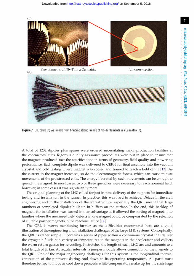
The first critical element for the magnets is the superconducting cable. In the case of the mainLHC magnets, this was based on relatively mature technology using niobium–titanium (Nb–Ti)as the superconductor. The filaments of Nb–Ti are embedded into a matrix of copper to makethe individual strands. With a diameter of 7 μm, around 8000 filaments are used for each 1 mmdiameter strand. Either 28 or 36 of these strands are then braided together to form the classical flat‘Rutherford’ cable. In figure 7, the structure of the individual strands is shown (b) together withthe final braided cable (a). A total of 7000 km of cable were manufactured for the LHC.
The assembly of the magnet cold masses was performed by three European firms, basedon a recipe specified by CERN [12]. CERN also acted as the main supplier of components.
on September 5, 2018http://rsta.royalsocietypublishing.org/Downloaded from
7
rsta.royalsocietypublishing.orgPhil.Trans.R.Soc.A373:20140044
.........................................................
fine filaments of Nb–Ti in a Cu matrix
(b)
(a)full cross- section
Figure 7. LHC cable (a) was made from braiding strands made of Nb–Ti filaments in a Cu matrix (b).
A total of 1232 dipoles plus spares were ordered necessitating major production facilities atthe contractors’ sites. Rigorous quality assurance procedures were put in place to ensure thatthe magnets produced met the specifications in terms of geometry, field quality and poweringperformance. Each complete dipole was delivered to CERN for final assembly into the vacuumcryostat and cold testing. Every magnet was cooled and trained to reach a field of 9 T [13]. Asthe current in the magnet increases, so do the electromagnetic forces, which can cause minutemovements of the pre-stressed coils. The energy liberated by such movements can be enough toquench the magnet. In most cases, two or three quenches were necessary to reach nominal field,however, in some cases it was significantly more.
The original planning of the LHC called for just-in-time delivery of the magnets for immediatetesting and installation in the tunnel. In practice, this was hard to achieve. Delays in the civilengineering and in the installation of the infrastructure, especially the QRL meant that largenumbers of completed dipoles built up in buffers on the surface. In the end, this backlog ofmagnets for installation was turned into an advantage as it allowed the sorting of magnets intofamilies where the measured field defects in one magnet could be compensated by the selectionof suitable partner magnets in the machine lattice [14].
The QRL is worth mentioning further, as the difficulties encountered here are a goodillustration of the engineering and installation challenges of the large LHC systems. Conceptually,the QRL is rather simple. It contains a series of pipes within a continuous cryostat that deliverthe cryogenic fluids at a variety of temperatures to the magnets in the accelerator and collectsthe warm return gasses for re-cooling. It stretches the length of each LHC arc and amounts to atotal length of 20 km. At regular intervals, a jumper module allows connection of the magnets tothe QRL. One of the major engineering challenges for this system is the longitudinal thermalcontraction of the pipework during cool down to its operating temperature. All parts musttherefore be free to move as cool down proceeds while compensators make up for the shrinkage
on September 5, 2018http://rsta.royalsocietypublishing.org/Downloaded from

8
rsta.royalsocietypublishing.orgPhil.Trans.R.Soc.A373:20140044
.........................................................
of the pipes. The jumper modules themselves represent a significant additional complexity, asthey must remain fixed with respect to the adjacent magnets. They also contain a large numberof control valves for optimizing the cooling of the machine elements. Problems during theindustrialization of the manufacture of the QRL components as well as difficulties installing,connecting and aligning the elements in the tunnel lead to significant delays in completing thispart of the infrastructure.
(b) InstallationOnly one shaft was made large enough to lower a complete dipole assembly. The dipoles werelowered and then transported in the tunnel to their chosen location. The transport aroundthe tunnel was done with optically guided electrical tractors moving at a maximum speed of3 km h−1. In total, these tractors travelled approximately 20 000 km to deliver all magnets to theirdesignated locations.
The arcs of the LHC consist of a 3 km continuous cryostat. Each magnet therefore had tobe connected electrically, hydraulically and mechanically to its neighbours. As the magnetswould be operated in a He II environment all hydraulic and vacuum connections werewelded, rather than clamped. The electrical connections were spliced together, soldered andtested to ensure that connection resistance was sufficiently low. In total, around 250 000 high-quality welds and over 10 000 high-current electrical splices were made in the difficult tunnelenvironment [15].
5. Operational challengesOn 10 September 2008, everything was ready for first injection; the machine had been cooleddown over the previous months and all circuits tested to the level needed for injection of beam.The machine was started with a blaze of publicity and within a few hours circulating beam wasestablished. Over the next 9 days, rapid progress was made in commissioning the various systemswith low-intensity beams.
Interleaved with beam commissioning, periods were set aside for commissioning the magnetsto high energy. This work had been progressing very well and seven of the eight sectors ofthe machine had been commissioned to the equivalent field of 5 TeV (6 T in the main dipoles).However, during the commissioning of the last sector, a resistive zone developed in a faultyinter-magnet bus-bar splice. The resulting arc punctured the helium enclosure and a total of275 MJ of energy were dumped into the joint and the liquid helium causing spectacular damage.The resulting repairs took almost 12 months to complete and involved exchanging a total of 54magnets and cleaning around 4 km of beam vacuum pipe. An extensive inquiry was held tounderstand exactly what had happened and to put in place measures to ensure that this kindof event could never happen again [16]. An extensive modification of the magnet protectionsystem was undertaken to allow this system to monitor the inter-magnet connections and passiveprotection, such as larger pressure relief valves and more robust magnet anchoring to the groundwere installed.
This event was a lesson in the energies involved when powering the LHC. As a result of thisincident, the protection of the accelerator from the energy in the beam, as well as from its ownstored energy, was to become a critical aspect in the operation of the LHC.
(a) Stored energyWhen at operating temperature, the magnets of the LHC have essentially zero resistance toelectrical current flow. They do, however, have an inductance and this is quite high, at 100 mH perdipole. As all dipoles in a given octant of the machine are connected in series, the inductance (L)of the overall circuit is around 15 H. The energy stored in an inductor is given by E = 1/2 · L · I2,where I is the current. This amounts to 1.1 GJ of stored magnetic energy per sector and 10 GJ
on September 5, 2018http://rsta.royalsocietypublishing.org/Downloaded from

9
rsta.royalsocietypublishing.orgPhil.Trans.R.Soc.A373:20140044
.........................................................
for the whole machine when operated at the nominal current of 13 000 A. This energy must becontrolled very carefully. In case of a powering failure, or other abnormality, it is necessary toextract this energy to ground as quickly as possible in order to avoid damage. In the LHC, themagnet protection systems are designed to extract this energy within approximately 105 s ofdetecting a fault. The magnets and powering systems themselves are designed to accommodatethis time constant.
In the case of the beam, the stored energy is 362 MJ when the LHC is running at nominalenergy and beam current. This, however is in the form of a series of bunches moving atessentially the speed of light around the machine. In this case any anomaly must be detectedvery rapidly and the beam dumped, before the onset of damage. The machine protection systemis designed to detect and dump the bean within a few hundred microseconds (three turns of theaccelerator) [17].
The operational mode of an accelerator is by definition one of the most exciting andchallenging periods. In this mode, the different elements of the LHC have to act as a unifiedwhole, so that the beam can be injected, accumulated, accelerated and brought into collision.The control system and applications software are crucial elements that allow the operators torun through the different processes and prepare for a data taking run. Beams will only survivethe process if all systems are perfectly synchronized. Second-order corrections are carried out bydedicated feedback systems, which measure small deviations from the required conditions andapply corrections. All these systems are, of course, totally dependent on the beam instrumentationsystem, which must provide reliable observational data on various beam parameters at all times.In addition, all safety systems must be fully validated because stored energy of the beam as wellas the magnetic stored energy has huge destructive capability. As an example, one system will bementioned in more detail. This is the collimation system, which helps to protect the LHC fromthe stored energy in the beam.
The beam in an accelerator is not a rigid object; instead it is a loose collection of particles,which has a Gaussian distribution in its transverse dimensions. Although the vast majority of theparticles are within the core of the beam there will always be some at higher amplitudes in thetails of the distribution. The energy of each particle in the beam is so high that even a very smallfraction hitting the surface of the superconducting magnets of the machine can cause a quench,and worse still damage. The collimation system is designed to protect the cold aperture of themachine by removing the outlying particles cleanly and absorbing their energy. Each collimatorconsists of pairs of jaws, 1.2 m long that can be moved close to the beam. Depending on theamount of energy that is will be deposited in the jaws during normal operation, these can bemade of carbon, tungsten or copper. Some act in the horizontal plane, some in the vertical planeand others in the skew directions (at 45◦ to the horizontal). In total, 108 collimators are presentlyinstalled in the LHC [18,19].
In order to function properly, the collimators must be adjusted precisely with respect to theposition of the beam, while the jaw gaps themselves are changed during the different partsof the operational cycle of the machine. The collimators closest to the beam are known as theprimaries, where initial scattering of the beam particles to be removed occurs. Secondary andtertiary collimators then absorb the showers generated by the initial interaction. To avoid damagea very strict hierarchy of collimator positions must be observed and the position of each collimatormust be maintained accurate to around 10 μm with respect to the centre of the beam. The set-upand qualification of the collimation system is established during special low-intensity runs andthen operation relies on excellent reproducibility of the beam conditions from run to run, and onsophisticated beam feedback and control systems.
Run 1 of the LHC lasted 3 years seeing the machine advance from initial commissioningthen through a series of intensity increases to reach a peak instantaneous luminosity of 7 ×10+33 cm−2 s−1. Figure 8 shows the integrated luminosity evolution over the 3 years.
This remarkable performance was not only due to the quality of the design of the machineand its sub-systems but also due to the reliability of the equipment making up the various sub-systems. Many of these sub-systems are huge installations in their own right. As an example the
on September 5, 2018http://rsta.royalsocietypublishing.org/Downloaded from

10
rsta.royalsocietypublishing.orgPhil.Trans.R.Soc.A373:20140044
.........................................................
252010, 7 TeV, 44.2 pb–1
2011, 7 TeV, 6.1 fb–1
2012, 8 TeV, 22.8 fb–120
15
date (UTC)
10
tota
l int
egra
ted
lum
inos
ity (
fb–1
)
×1005
0
1 Apr
25CMS
20
15
10
5
0
1 May
1 Jun
1 Jul
1 Aug
1 Sep
1 Oct
1 Nov
1 Dec
Figure 8. Integrated luminosity during LHC Run 1 (courtesy CMS).
13.8%
accessset-upinjection physics
squeezeramp
36.5%
SB time: 73.2 days total time: 200.5 days
5.0%
2.1%
15.0%
27.6%
Figure 9. Operational efficiency during the 2012 proton run.
operational efficiency of the LHC during the proton run is given in figure 9. The time is split intosix modes as follows.
— ‘Set-up’ corresponds to the preparatory period where the machine is being made readyfor taking beam.
— During ‘Injection’, bunches are progressively accumulated in the LHC by transfer fromthe injector complex. During 2012, up to 144 bunches could be transferred in a singleinjection.
— ‘Ramp’ corresponds to the period where the energy of the beam is progressively increasedfrom the injection level (0.45 TeV) to the collision energy. During Run 1, this energy waslimited to 3.5 or 4 TeV per beam.
on September 5, 2018http://rsta.royalsocietypublishing.org/Downloaded from

11
rsta.royalsocietypublishing.orgPhil.Trans.R.Soc.A373:20140044
.........................................................
— ‘Squeeze’ corresponds to the period where the beams are adjusted prior to collisions. Thisconsists of adjusting the focusing of the beams around the interaction points to minimizethe beam size and hence maximize the luminosity.
— ‘Physics’ is the period during which the beams collide in a stable way, the experimentaldetectors are turned on and are gathering collision data. The luminosity delivered to theexperiments during this period is integrated and over many physics fills forms the plotsshown in figure 8.
A figure of 36.5% for the fraction of the scheduled time spent with stable colliding beams is quiteremarkable for a machine of the size and complexity of the LHC.
6. Future challengesThe LHC is presently undergoing major works during a long shutdown, lasting almost 2 years.This shutdown is to prepare all systems for operation at nominal energy and involves a numberof measures to consolidate the machine in the wake of the 2009 incident. In addition, after3 years of almost continuous operation the maintenance and upgrade of many technical systemsis needed. At the same time, the injector complex for the LHC is being upgraded and maintainedready to deliver the high-intensity, high-quality beams needed to increase the performance of theLHC further.
The LHC will begin re-commissioning with beam early in 2015 and will then run until themiddle of 2018, with only short technical stops over the new-year period. During this ‘Run 2’,the operation of the machine will be established at 6.5–7.0 TeV per beam and the performancepushed beyond the nominal design luminosity of 1 × 10+34 cm−2 s−1. As well as almost doublingthe energy of collisions, the number of bunches circulating in the machine will also be increased bya factor 2. This will be an exciting period as the machine will again move into unknown territoryand systematic searches for physics beyond the standard model will be high on the priority list. Inaddition, the increased performance will provide significantly more statistics on the Higgs bosondiscovered in 2012, allowing its nature to be investigated in more detail.
In 2018–2019, a second long shutdown is planned. Lasting around 18 months, this will allowmajor upgrades to the LHC detectors as well as the machine elements. The aim here is to increasethe performance of the machine again to around three times the nominal design value. By theend of 2022, it is forecast that the LHC will have delivered approximately 300 fb−1 to CMS andATLAS. This value represents the initial design goal for the LHC.
In 2013, the update of the European Strategy for Particle physics was published [20]. Thisprocess, undertaken every 5 years brings together the community and funding agencies to setout the major strategic goals for the discipline. In the recent update, the highest priority wasestablished to maximize the potential of the LHC by launching an upgrade programme for themachine and detectors in order to collect a factor of 10 more data by the early 2030s [21]. Theambitious programme to deliver 3000 fb−1 to ATLAS and CMS is now launched as a majorinternational project called HL-LHC (high-luminosity LHC).
The HL-LHC aims to maximize the luminosity production of the LHC by re-optimizing theparameters of equations (2.2) and (2.3). The key parameters here are the brightness of the beamfrom the injectors (defined as Nb/εn), reduction of the beam size at the IP, via lower β∗ and amechanism for controlling the luminosity, via the factor F (equation (2.3)). The higher brightnessbeam concerns upgrades to the injector complex, the other two refer to upgrades in the LHCitself. A full description of the upgrade plans for the LHC is outside the scope of this paper.However, a couple of examples will be given here of the technical challenges concerning thisluminosity upgrade.
The modifications to the LHC for HL-LHC will involve essentially re-building around 1.2 kmof the machine with new equipment. The major elements will be new final focus quadrupolesaround CMS and ATLAS. These wide-aperture quadrupoles will allow the β∗ (and hence thebeam size at the IP) to be reduced by a factor of 5. The technology of these new high-field magnet
on September 5, 2018http://rsta.royalsocietypublishing.org/Downloaded from

12
rsta.royalsocietypublishing.orgPhil.Trans.R.Soc.A373:20140044
.........................................................
qc
Figure 10. Schematic of the compensation of the crossing angle using crab cavities.
HWDR, JLAB,OD HWSR, SLAC-LARP DR, UK, TechX Kota, KEK
Figure 11. Compact 400 MHz crab cavities under development for the LHC.
quadrupoles has to be pushed considerably and their development and construction will formpart of an international collaboration [22]. The cable for these magnets must be constructed fromNb3Sn, which is a superconductor capable of generating the higher magnetic fields required inthis configuration. Intensive R&D is taking place at CERN, in the USA and in Japan to developthem. Unfortunately, the full benefit of the beam size reduction from the potentially lower β∗ willnot be directly available in the form of increased luminosity, as the reduction in beam size at the IPwill also reduce the factor F, in equations (2.2) and (2.3). In order to overcome this and to providea mechanism for levelling the luminosity (i.e. keeping it constant through the greater part of aphysics coast), a second technical innovation is required, namely crab cavities.
Crab cavities, installed at either side of the IP, can be used to kick the head and tail of eachbunch in such a way that they effectively cross head-on, in spite of the crossing angle. A schematicis shown in figure 10.
Crab cavities are a relatively new technology that has so far only been experimentally verifiedin the KEKB accelerator in Japan, and then only with leptons [23]. In addition, for the LHC casecompact cavities must be developed that will fit within the constraints of the machine, mostnotably the 194 mm distance between the two beams. Figure 11 shows schematic drawings ofseveral crab cavity designs being developed by international partners in the USA, UK and Japan.Each superconducting cavity type will be tested at CERN before a final decision on the installationin the LHC can be taken.
7. ConclusionAfter 25 years of design and development, the LHC has been commissioned at intermediateenergy and during its first 3-year run has performed well and beyond expectations. Already, atthis early stage, it has delivered large amounts of collision data to the experiments and allowedthem to discover and observe the properties of a Higgs boson at 126 GeV. A 2-year shutdown of
on September 5, 2018http://rsta.royalsocietypublishing.org/Downloaded from

13
rsta.royalsocietypublishing.orgPhil.Trans.R.Soc.A373:20140044
.........................................................
the machine is now underway with the aim of preparing the machine for ‘nominal’ operationin terms of energy and luminosity. LHC will begin operation in 2015 at 6.5–7 TeV per beam andrun for 3.5 years before the next long shutdown. This period will be very exciting in terms of thepossible observation of physics beyond the standard model. To follow from this, an upgrade planhas been elaborated and launched to provide a factor of 10 more data than was foreseen in theoriginal design. The larger statistics will allow more precise investigations of the Higgs boson aswell as searching for very rare new processes.
Throughout the various stages, the LHC has had to confront a number of technical, engineeringand operational challenges. A few of these have been mentioned here to give a flavour of thecomplexity of the machine and its detectors.
Acknowledgements. I have profited enormously with material and advice from numerous colleagues at CERNwithout which this paper would not have been possible. I sincerely thank them.
References1. Jackson JD (ed.). 1986 Conceptual design of the superconducting super collider. SSC-SR-2020.
Washington, DC: Washington University Research Assoc.2. Asner A et al. (eds). 1984 ECFA-CERN workshop on Large Hadron Collider in the LEP tunnel.
CERN-84-10-V-1 (21–27 Mar 1984). Geneva, Switzerland: CERN.3. Chao AW, Tigner M (eds). 1998 Handbook of accelerator physics and engineering. Singapore: World
Scientific.4. Evans L (ed.). 2009 The Large Hadron Collider, a marvel of technology. Lausanne, Switzerland:
EPFL Press.5. Brüning O, Collier P, Lebrun P, Myers S, Ostojic R, Poole J, Proudlock P (eds). 2004 LHC design
report, volume 1: the LHC machine. CERN 2004-003-V1. Geneva, Switzerland: CERN.6. Brüning O, Collier P, Lebrun P, Myers S, Ostojic R, Poole J, Proudlock P (eds). 2004 LHC
design report, vol. 2: the LHC infrastructure and general services. CERN 2004-003-V2, Geneva,Switzerland: CERN.
7. Tanabe JT. 2005 Iron dominated electromagnets. Singapore: World Scientific.8. Mess KH, Schmuser P, Wolf S. 1996 Superconducting accelerator magnets. Singapore: World
Scientific.9. Lebrun Ph. 1996 Cryogenic systems for accelerators, pp. 681–700. Frontiers of Accelerator
Technology. Singapore: World Scientific.10. Lebrun Ph, Tavian L. 2004 The technology of superfluid helium, p. 375. CERN 2004–008, Geneva,
Switzerland: CERN.11. Poole J, Silari M. 2001 The LEP dismantling project. SL-Note-2001-011-MR. Geneva, Switzerland:
CERN.12. Savary F et al. 2008 Description of the main features of the series production of the LHC main
dipole magnets. IEEE Trans. Appl. Supercond. 18, 220–225. (doi:10.1109/TASC.2008.920632)13. Siemko A, Pugnat P. 2008 Performance evaluation and quality assurance management during
the series power tests of LHC main lattice magnets. IEEE Trans. Appl. Supercond. 18, 126–131.(doi:10.1109/TASC.2008.921904)
14. Fartoukh S, Giavannozzi M. 2012 Dynamic aperture computation for the as-built CERN LargeHadron Collider and impact of main dipoles sorting. Nucl. Instrum. Methods Phys. Res. A671,10–23. (doi:10.1016/j.nima.2011.12.052)
15. Tock JP, Bozzini D, Laurent F, Russenschuck S, Skozen B. 2004 Electro-mechanical aspects ofthe interconnection of the LHC superconducting corrector magnets. In CERN-LHC-Project-Report-724, Proc. 9th European Particle Accelerator Conference, Lucerne, Switzerland, 5–9 July 2004.
16. Chorowski M, Fydrych J, Modlinski Z, Polinski J, Tavian L, Wach J. 2010 Upgrade on riskanalysis following the 080919 incident in the LHC sector 3–4. CERN-ATS-Note-2010-033 TECH.Geneva, Switzerland: CERN.
17. Schmidt R et al. 2007 LHC machine protection. In LHC-PROJECT-Report-1053, Proc. 22ndParticle Accelerator Conference, Albuquerque, NM, USA, 25–29 Jun 2007.
18. Assmann R et al. 2003 Designing and building a collimation system for the high-intensity LHCbeam. In LHC-Project-Report-640, Proc. 20th IEEE Particle Accelerator Conference, Portland, OR,USA, 12–16 May 2003.
on September 5, 2018http://rsta.royalsocietypublishing.org/Downloaded from

14
rsta.royalsocietypublishing.orgPhil.Trans.R.Soc.A373:20140044
.........................................................
19. Salvachua B et al. 2013 Cleaning performance of the LHC collimation system up to 4 Tev. CERN-ACC-2013-0070. Geneva, Switzerland: CERN.
20. 2013. The European strategy for particle physics update 2013. CERN-Council-S/0106. Geneva,Switzerland: CERN.
21. Rossi L. 2011 LHC upgrade plans: options and strategy. In CERN-ATS-2011-257, Proc. 2ndInternational Particle Accelerator Conference, San Sebastian, Spain, 4–9 Sep 2011.
22. Rossi L, Bottura L, de Rijk G, Todesco E. 2011 Advanced accelerator magnets for upgrading theLHC. In CERN-ATS-2012-045, IEEE Trans. Appl. Supercond. 22 (2012), Proc. 22nd InternationalConference on Magnet Technology, Marseille, France, 12–16 September 2011.
23. Funakoshi Y. et al. 2008 Performance of KEKB with crab cavities. In Proc. 11th European ParticleAccelerator Conference, Genoa, Italy, 23–27 June 2008.
on September 5, 2018http://rsta.royalsocietypublishing.org/Downloaded from