thhee ssaamm33gg++ euusseerr gguuiidde · document history 18th may 2007 : start version 1.0 12th...
TRANSCRIPT

1
Intercel Pty. Ltd. A.C.N. 007 077 161 33 Glenvale Crescent Mulgrave VIC. Australia 3170 Email : [email protected] Internet : www.intercel.com.au
Ph : 61 3 9239 2000 Fax : 61 3 9561 2614
TThhee SSAAMM33GG++ UUsseerr GGuuiiddee Version 2.4
Document history 18th May 2007 : Start Version 1.0 12th June 2007 : Update SAM3G pictures Version 1.1 18th Oct 2007 : Update section 5 and section 8 Version 1.2 26th Oct 2007 : Update section 8.2.a Version 1.3 26th Oct 2007 : Update section 1,5,7 and 8 Version 1.4 24
th Mar 2009 : Update for SAM3G+ Version 2.0
27th
April 2012 : Update for LED indicator Version 2.1
18th
April 2013 : Update serial cable Version 2.2
17th
May 2013 : Update bands Version 2.3
15th
July 2013: Update Intercel logo and phone no. Version 2.4

2
Intercel Pty. Ltd. A.C.N. 007 077 161 33 Glenvale Crescent Mulgrave VIC. Australia 3170 Email : [email protected] Internet : www.intercel.com.au
Ph : 61 3 9239 2000 Fax : 61 3 9561 2614
Contents 1. Introduction 2. Safety precautions 3. Radio frequency exposure - SAR 4. WEEE Directive 2002/96/EC - disposal of old electronic equipment 5. Packaging 5.1 Contents 5.2 The packaging box 5.3 The production label 6. Functionality a. General b. The RJ45 socket c. The MiniB USB connector d. The SMB-Jack 50Ω antenna connector e. The USIM holder f. The LED status g. The Data cable 7. Electrical characteristics a. Power consumption b. RF bands c. Receive sensitivity d. Conducted transmit power tolerances e. Main antenna specifications f. Environmental characteristics 8. Operation 8.1. Using the USB port a. Installing the USB driver b. Firmware upgrade 8.2. Using the serial RS232 port a. General configuration b. Meter configuration c. AT commands

3
Intercel Pty. Ltd. A.C.N. 007 077 161 33 Glenvale Crescent Mulgrave VIC. Australia 3170 Email : [email protected] Internet : www.intercel.com.au
Ph : 61 3 9239 2000 Fax : 61 3 9561 2614
1. Introduction The SAM3G+ is a compact, light-weight, UMTS, HSPA based modem. It provides GSM, GPRS, EDGE and WCDMA connectivity. The SAM3G+ is a quad-band GSM/GPRS/EDGE 850MHz, 900MHz, 1800MHz, 1900MHz and a quad-band WCDMA/HSDPA : 850MHz, 900MHz,1900MHz, 2100MHz The SAM3G+ is designed for both mobile and fixed M2M applications. It has an RJ45 socket for both input voltage and serial RS232 signals, a MiniB USB connector, a SMB-Jack for antenna connection, a SIM holder and an LED indicator. The SAM3G+ is capable of sending/receiving SMS, Circuit switched data and Packet-switched data. SMB-Jack antenna connector
SIM holder LED indicator Mini USB connector RJ45 for input power and serial RS232 Type Approval GCF full type approval Mobile station modem Version Qualcomm’s MSM6290 TA code 35362602 EU approval CE-0682

4
Intercel Pty. Ltd. A.C.N. 007 077 161 33 Glenvale Crescent Mulgrave VIC. Australia 3170 Email : [email protected] Internet : www.intercel.com.au
Ph : 61 3 9239 2000 Fax : 61 3 9561 2614
2. Safety Precautions
The following safety precautions must be observed whenever the SAM3G+ modem is in operation or in service. Failure to comply with these precautions violates the safety standards of the design, manufacture and intended use of the product
- Switch off the SAM3G+ modem :
In hospitals or places where medical equipments may be in use.
In an aircraft
Refueling points
Explosive areas
- Restricted use of the SAM3G+ modem
Near any chemical plant
Near any Fuel depot
Areas with mobile phone warning signs Respect national regulations on the use of cellular devices. Road safety always comes first The SAM3G+ modem receives and transmit radio frequency energy while switched on, therefore interference can occur if the SAM3G+ is near TVs, radios, PCs or any inadequately shielded equipments. 3. Radio frequency exposure - SAR
The SAM3G+ modem is a low-power transceiver, similar to a typical handheld GSM/GPRS/UMTS mobile phone. When it is turned on, it will emit low-level radio frequency energy. There are different guidelines and standards around the world that govern the permitted levels of radio frequency exposure for general population. The levels include a safety margin to a human body. The Specific Absorption rate (SAR) is a measure of the rate at which radio frequency energy is absorbed by the body when exposed to radio frequency electromagnetic field. The SAR value is determined at the highest certified power level in the laboratory conditions, but the actual SAR level of the transceiver while operating can be well below this value. This is because the transceiver is designed to use minimum power to connect to the network. The SAM3G+ modem is approved to use in applications where the antenna is placed more than 21cm from the body. For other applications, the integrator is responsible for the local SAR requirements.

5
Intercel Pty. Ltd. A.C.N. 007 077 161 33 Glenvale Crescent Mulgrave VIC. Australia 3170 Email : [email protected] Internet : www.intercel.com.au
Ph : 61 3 9239 2000 Fax : 61 3 9561 2614
4. WEEE directive 2002/96/EC, disposal of old electronic equipment
This symbol on the product indicates that this product shall not be treated as household waste . It must be placed at an appropriate collection point for the recycling of electrical and electronic equipments. By ensuring the correct disposal of this equipment, it will help the environment and human’s health. The recycling will help to conserve the natural resources. The SAM3G+ product is RoHS compliant

6
Intercel Pty. Ltd. A.C.N. 007 077 161 33 Glenvale Crescent Mulgrave VIC. Australia 3170 Email : [email protected] Internet : www.intercel.com.au
Ph : 61 3 9239 2000 Fax : 61 3 9561 2614
5. Packaging
5.1 Contents The SAM3G+ package consists of :
- A SAM3G+ modem - A data cable - A short specification of the SAM3G+ and its pinouts - A SAM3G+ User Guide
5.2 The packaging box The carton box diameter is 120mm x 95mm x 60mm The Data cable is 2m long The Label diameter is 50mm x 33mm The Power supply is available on request. It is recommended that the SAM3G+ is powered using a 12Vdc/1A power supply. The antenna is also available on request. Please make sure the correct antenna is used to get optimised performance from the SAM3G+ (see section 7.e. Main Antenna specifications). 5.3 The production label

7
Intercel Pty. Ltd. A.C.N. 007 077 161 33 Glenvale Crescent Mulgrave VIC. Australia 3170 Email : [email protected] Internet : www.intercel.com.au
Ph : 61 3 9239 2000 Fax : 61 3 9561 2614
The production part number is located at the back of the SAM3G+, which includes :
- The product model - The software Version - The Hardware Version - The IMEI number - The manufacturer - The part number
Product Model: SAM3G+ AMR Software : Version 1.C Hardware : Version 3.2
IMEI
352679010 049570
Made by: Intercel - N592 Part number : ASSSAM3G+AMR

8
Intercel Pty. Ltd. A.C.N. 007 077 161 33 Glenvale Crescent Mulgrave VIC. Australia 3170 Email : [email protected] Internet : www.intercel.com.au
Ph : 61 3 9239 2000 Fax : 61 3 9561 2614
6. Functionality
a. General
The SAM3G+ modem consists of an RJ45 connector for serial port and input power, a miniB USB connector, an SMB Jack antenna connector and a SIM holder. The LED indicator, located on top, indicates the SAM operating status. SMB connector
3G ENGINE
Switching Power Supply
RS232 Serial Data Interface
SIM Interface
RJ45 Socket
MiniB USB
Connector
LED Indicator
The SAM3G+ Functional Block Diagram
uController
9
Intercel Pty. Ltd. A.C.N. 007 077 161 33 Glenvale Crescent Mulgrave VIC. Australia 3170 Email : [email protected] Internet : www.intercel.com.au
Ph : 61 3 9239 2000 Fax : 61 3 9561 2614
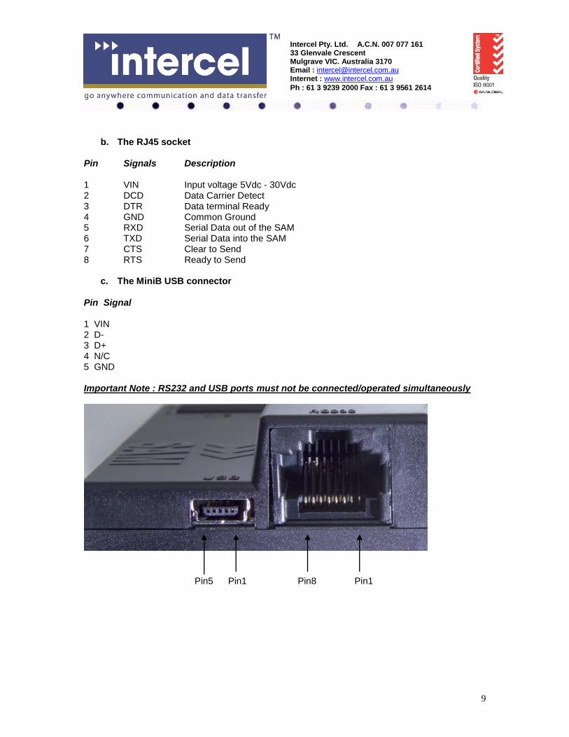
b. The RJ45 socket
Pin Signals Description 1 VIN Input voltage 5Vdc - 30Vdc 2 DCD Data Carrier Detect 3 DTR Data terminal Ready 4 GND Common Ground 5 RXD Serial Data out of the SAM 6 TXD Serial Data into the SAM 7 CTS Clear to Send 8 RTS Ready to Send
c. The MiniB USB connector Pin Signal 1 VIN 2 D- 3 D+ 4 N/C 5 GND Important Note : RS232 and USB ports must not be connected/operated simultaneously
Pin5 Pin1 Pin8 Pin1

10
Intercel Pty. Ltd. A.C.N. 007 077 161 33 Glenvale Crescent Mulgrave VIC. Australia 3170 Email : [email protected] Internet : www.intercel.com.au
Ph : 61 3 9239 2000 Fax : 61 3 9561 2614
d. The SMB-Jack 50Ω antenna connector
e. The USIM holder To insert the SIM card, remove the door by sliding it back toward the end. Make sure the SIM card faces the right way as indicated on the box. Voltage levels over this USIM interface complies with 3GPP standards
f. The LED status The LED indication has the following status :
- LED on steady: The SAM3G+ is searching for network. - LED flashes very slowly: No SIM card inserted. - LED flashes regularly: The SAM3G+ is on and connected to the network, but not
transmitting or receiving data. - LED flashes at fast rate : The SAM3G+ is in use (transmit/receive data) - LED is off : No power

11
Intercel Pty. Ltd. A.C.N. 007 077 161 33 Glenvale Crescent Mulgrave VIC. Australia 3170 Email : [email protected] Internet : www.intercel.com.au
Ph : 61 3 9239 2000 Fax : 61 3 9561 2614
g. The data cable
The data cable is 2m long. It consists of an RJ45 plug, a DB9-female connector and a 2-wire input power. 5 4 3 2 1
9 8 7 6 DB9 Signals RJ45 Description 1 DCD 2 Data Carrier Detect 2 RXD 5 Serial Data out of the SAM3G+ 3 TXD 6 Serial Data into the SAM3G+ 4 DTR 3 Not used 5 GND 4 Common Ground 6 DSR 8 CTS 7 Clear to Send 7 RTS 8 Ready to Send 9 RI Not used 1 RED wire : Input voltage from 5Vdc to 32Vdc 4 BLACK wire : Power Ground
7. Electrical characteristics

12
Intercel Pty. Ltd. A.C.N. 007 077 161 33 Glenvale Crescent Mulgrave VIC. Australia 3170 Email : [email protected] Internet : www.intercel.com.au
Ph : 61 3 9239 2000 Fax : 61 3 9561 2614
a. Power consumption
Vin = 12Vdc HSDPA/WCDMA GSM/GPRS/EDGE Idle mode 31mA 31mA Standby mode 105mA 80mA Average In-Use : 2Mbps@10dBm Tx 158mA HSUPA - 7.2Mbps Rx 158mA HSDPA - 384Kbps@10dBm Tx 137mA WCDMA - GSM CSD (9600bps) - 87mA GPRS PSD - 110mA EDGE - 137mA
b. RF bands GSM850 : Tx = 824MHz - 849MHz, Rx = 869MHz - 894MHz EGSM900 : Tx = 880MHz - 915MHz, Rx = 925MHz - 960MHz DCS1800 : Tx = 1710MHz - 1785MHz, Rx = 1805MHz - 1880MHz PCS1900 : Tx = 1850MHz - 1910MHz, Rx = 1930MHz - 1990MHz UMTS2100 : Tx = 1920MHz - 1980MHz, Rx = 2110MHz - 2170MHz UMTS1900 : Tx = 1850MHz - 1910MHz, Rx = 1930MHz - 1990MHz UMTS900 : Tx = 880MHz - 915MHz, Rx = 925MHz - 960MHz UMTS850 : Tx = 824MHz - 849MHz, Rx = 869MHz - 894MHz
c. Receive sensitivity Band Typical Rx Sensitivity Maximum Rx Sensitivity (dBm) (dBm) GSM850 (2% ber) CS -107.5 -106 EGSM900 (2% ber) CS -107.5 -106 DCS1800 (2% ber) CS -106.5 -105 PCS1900 (2% ber) CS -106.5 -105 UMTS2100(.1% ber) 12.2Kbps -110.5 -109 UMTS1900(.1% ber) 12.2Kbps -110.5 -109 UMTS900(.1% ber) 12.2Kbps -110.5 -109 UMTS850(.1% ber) 12.2Kbps -111.5 -110 Notes :
- Ber : bit error rate - CS : Circuit-switched

13
Intercel Pty. Ltd. A.C.N. 007 077 161 33 Glenvale Crescent Mulgrave VIC. Australia 3170 Email : [email protected] Internet : www.intercel.com.au
Ph : 61 3 9239 2000 Fax : 61 3 9561 2614
d. Conducted Transmit Power tolerances Parameter Conducted Tx Power Note GSM850 & GSM900 CS +32dBm ±1dBm GMSK mode, connectorized (Cl.4) +27dBm ±1dBm 8PSK mode, connectorized (Cl.E2) DCS1800 & PCS1900 CS +29dBm ±1dBm GMSK mode, connectorized (Cl.1) +26dBm ±1dBm 8PSK mode, connectorized (Cl.E2) UMTS1900,900&850 12.2Kbps +23dBm ±1dBm connectorized (Cl.3) UMTS2100 12.2Kbps +23dBm ±1dBm connectorized (Cl.3)
e. Main antenna specifications Max cable loss 0.5dBm Impedance 50Ω Max allowed VSWR 3:1 The maximum antenna gain recommended, for consideration against RF exposure and ERP/EIRP limits, is :
- In Cellular band : 5dBi - In PCS band : 4dBi
f. Environmental characteristics
Operating temperature -25°C to 60°C full RF performance 60°C to 75°C reduced RF performance Storage temperature -40°C to 85°C Humidity 85% relative humidity (non-condensing)

14
Intercel Pty. Ltd. A.C.N. 007 077 161 33 Glenvale Crescent Mulgrave VIC. Australia 3170 Email : [email protected] Internet : www.intercel.com.au
Ph : 61 3 9239 2000 Fax : 61 3 9561 2614
8. Operation
The SAM3G+ can support either the USB port or the Serial RS232 port. The port configuration is done at the point of sale. Do not operate these 2 ports at the same time ! 8.1 Using the USB port
a. Installing the USB driver
Note : If the old driver version has been installed, it must be removed, before installing the latest driver. To uninstall the old driver, follow these steps :
- Open the Control Panel - Double click System, System Properties window appears - Select the Hardware tab - Select the Device Manager - Expand the Universal Serial Bus controllers to show the installed devices. - Right click the Sierra Wireless MC87xx device entry and choose Uninstall. - Click OK to confirm.
Step1 : Locate and run the DriverInstaller.exe . Note that there is no feedback, just wait a few moments for the program to run. Step2 : Connect the SAM3G+ to the PC, using the supplied USB cable. Several Found New Hardware balloons appear above the tool tray as the system detects the new devices. After the devices are detected, the Device Manager will show, in the following categories :
- Network Adapters : Sierra Wireless HSDPA Network adapter. - Port (COM&LPT) :
Sierra Wireless AT Command port (UMTS)
Sierra Wireless CNS port (UMTS)
Sierra Wireless Data Port (UMTS)
Sierra Wireless DM Port (UMTS) - Universal Serial Bus Controllers : Sierra Wireless MC87xx device
b. Firmware upgrade
The USB port is used for firmware upgrade. Refer to the SAM3G+FirmwareUpgrade document for further details.

15
Intercel Pty. Ltd. A.C.N. 007 077 161 33 Glenvale Crescent Mulgrave VIC. Australia 3170 Email : [email protected] Internet : www.intercel.com.au
Ph : 61 3 9239 2000 Fax : 61 3 9561 2614
8.2 Using the Serial RS232 port The RS232 default configuration is :
- Terminal speed : 115200bps (+IPR=115200) - Data format : 8 data bits 1 stop bit (+ICF=3,3) - Hardware RTS, CTS flow control (+IFC=2,2) - No auto-answer (S0=0)
There are 6 serial data signals available at the RJ45 connector, namely DCD, DTR, RXD, TXD, RTS and CTS. There is an option for RI (Ring Indicator) signal instead of DTR signal. This configuration allows any external controller to communicate with the SAM3G+ at 115200bps over the serial port. The external device can set up the SAM3G+ modem using AT commands, can tranfer Circuit-switched data or Packet-switched data. With packet-switched data, the external device must be capable of communicating using PPP, TCP/IP or UDP/IP.
Setup example : Serial port connection to a PC
c. AT commands : The SAM3G+ modem supports most of the AT commands specified in the following standards :
- 3GPP TS 27.005 : Control SMS functions for devices on GSM/WCDMA networks - 3GPP TS27.007 : Control devices operating on GSM/WCDMA networks - ITU-T V.250 : Control serial communications over an asynchronous interface
For details of the AT commands, refer to the “Supported AT command” and “Extended AT commands” manuals.