thickness design for ambiguous cylinder illusion...thickness design for ambiguous cylinder illusion...
TRANSCRIPT
Thickness Design for Ambiguous Cylinder Illusion
Kokichi Sugihara∗
Meiji University, 4-21-1 Nakano, Nakano-ku, Tokyo 164-8525, Japan
Abstract
This paper proposes methods for giving as uniform a thickness aspossible to a class of illusion solids called ambiguous cylinders. Ambiguouscylinders are solids that have two quite different appearances when seenfrom two specific viewpoints, and thus create the impression of impossibleobjects. In order to realize them as physical objects, we have to givethem thickness. However, it is impossible to give a completely uniformthickness despite this being desirable. Instead we have to content ourselveswith second-best methods. For this purpose, this paper proposes threealternative strategies for creating objects as uniform as possible. Eachstrategy has its own merits and demerits, and hence users can choosetheir method according to their priorities for the visual effects which theywant to emphasize.
Keywords: Optical illusion, impossible object, anomalous cylinder, am-biguous object, uniform thickness.
1 Introduction
Optical illusions are perceptual phenomena in which what we see differs fromreality. Historically, optical illusions were found using 2D pictures [6–8, 10, 11],but recently many new illusions have been discovered or invented using 3D ob-jects [3,13,14,17]. Optical illusions can be mysterious, surprising, inspiring, andbeautiful. Therefore, they are potential resources for new products in many in-dustrial fields such as education, architecture, museum curation, entertainment,art, advertising, and tourism.
The author recently found a method for designing cylindrical objects thateach have two desired appearances when seen from two specific viewpoints.This class of objects creates an optical illusion when viewed directly and ina mirror simultaneously. For example, a cylinder with a circular cross-sectionchanges to a cylinder with a rectangular cross-section, a full moon cross-sectionto a star-shaped section, and a diamond-shaped cross-section to a heart-shapedcross-section. These are called ambiguous cylinders because their appearances
∗This manuscript was published in Japan Journal of Industrial and Applied Mathematics,vol. 35 (2017), pp. 391–409.
1

are ambiguous [15]. This concept was also extended to “partly invisible objects”for which parts of the objects disappear in a mirror [16].
The ambiguous cylinder illusion can be considered as a variant of the well-known illusion called trompe l’œil or anamorphosis, in which pictures paintedon planar surfaces or on the surfaces of 3D objects give meaningful appearancesonly when they are seen from a unique special viewpoint [11, 17]. Ambiguouscylinders, on the other hand, give meaningful appearances when seen from twospecial viewpoints. In this sense, the ambiguous cylinder illusion might beregarded as double trompe l’œil illusion.
However, the design method proposed in [15] only creates surfaces withoutthickness. This is okay conceptually, but not satisfactory if we want to constructphysical models because thickness is necessary to make the objects rigid.
Ideally we want to make the cylinder surfaces such that they have uniformthickness. That is, we want to construct a cylinder so that its thickness ap-pears to be uniform from both of the viewpoints. However, this requirement isnot consistent with the nature of an ambiguous cylinder. There is a trade-offbetween uniform thickness and the quality of the appearances: If we want toachieve uniform thickness, we have to change the appearances of the cylinderfrom the desired ones, and if we want to keep the desired appearances, we haveto give up having complete uniformness of thickness.
In this paper, we present several alternative methods for handling this in-consistency. Which method to use depends on the pair of appearances of theambiguous cylinder and the preference of the designer. Hence, the contributionof this paper is to offer a menu from which designers can select the method thatis most suitable for their aims and preferences.
We first review the method for constructing ambiguous cylinders withoutthickness (section 2) before presenting the problem of thickness design (section3). Then, we define some concepts and procedures as preparation (section 4),propose three methods for handling the inconsistency (section 5), show addi-tional examples (section 6), and give concluding remarks (section 7).
2 Review of Ambiguous Cylinders
An ambiguous cylinder is a cylindrical object that has two different appearanceswhen seen from two different specific viewpoints. It creates an optical illusion inthe sense that the two appearances are so different that it is almost unbelievablethat they could come from the same object. In particular, if the cylinder isreflected in a mirror, the viewer has the impression that the object changes toanother object in the mirror instead of being a normal mirror image.
Fig. 1 shows an example of an ambiguous cylinder. In this figure, (a) showsa scene with an object and a vertical mirror behind it. In the direct view of theobject, it appears to be a cylinder whose cross-section is a circle, in other words,the outline of a full moon, while the mirror image appears to be a cylinder witha star-shaped cross-section. Both the full moon shape and the star shape appearto be planar curves obtained by cutting the cylinder with a horizontal plane,
2
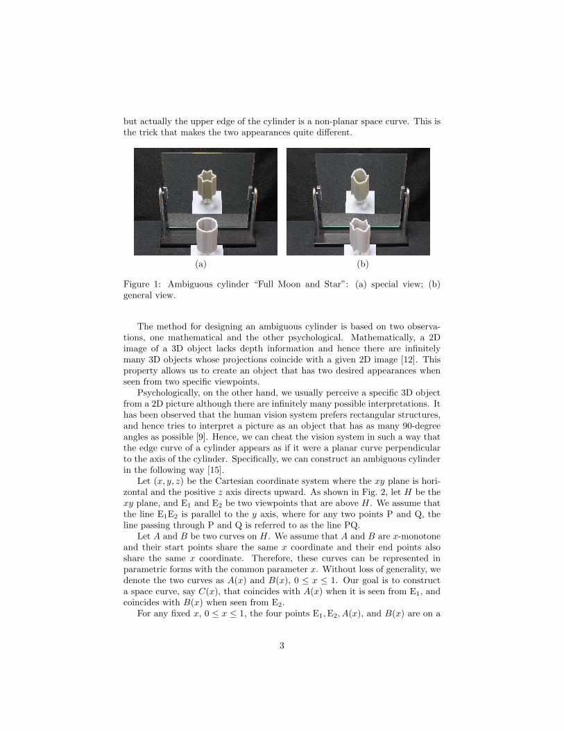
but actually the upper edge of the cylinder is a non-planar space curve. This isthe trick that makes the two appearances quite different.
(a) (b)
Figure 1: Ambiguous cylinder “Full Moon and Star”: (a) special view; (b)general view.
The method for designing an ambiguous cylinder is based on two observa-tions, one mathematical and the other psychological. Mathematically, a 2Dimage of a 3D object lacks depth information and hence there are infinitelymany 3D objects whose projections coincide with a given 2D image [12]. Thisproperty allows us to create an object that has two desired appearances whenseen from two specific viewpoints.
Psychologically, on the other hand, we usually perceive a specific 3D objectfrom a 2D picture although there are infinitely many possible interpretations. Ithas been observed that the human vision system prefers rectangular structures,and hence tries to interpret a picture as an object that has as many 90-degreeangles as possible [9]. Hence, we can cheat the vision system in such a way thatthe edge curve of a cylinder appears as if it were a planar curve perpendicularto the axis of the cylinder. Specifically, we can construct an ambiguous cylinderin the following way [15].
Let (x, y, z) be the Cartesian coordinate system where the xy plane is hori-zontal and the positive z axis directs upward. As shown in Fig. 2, let H be thexy plane, and E1 and E2 be two viewpoints that are above H. We assume thatthe line E1E2 is parallel to the y axis, where for any two points P and Q, theline passing through P and Q is referred to as the line PQ.
Let A and B be two curves on H. We assume that A and B are x-monotoneand their start points share the same x coordinate and their end points alsoshare the same x coordinate. Therefore, these curves can be represented inparametric forms with the common parameter x. Without loss of generality, wedenote the two curves as A(x) and B(x), 0 ≤ x ≤ 1. Our goal is to constructa space curve, say C(x), that coincides with A(x) when it is seen from E1, andcoincides with B(x) when seen from E2.
For any fixed x, 0 ≤ x ≤ 1, the four points E1,E2, A(x), and B(x) are on a
3
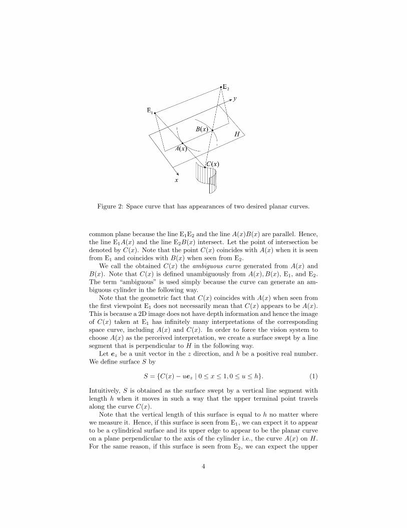
Figure 2: Space curve that has appearances of two desired planar curves.
common plane because the line E1E2 and the line A(x)B(x) are parallel. Hence,the line E1A(x) and the line E2B(x) intersect. Let the point of intersection bedenoted by C(x). Note that the point C(x) coincides with A(x) when it is seenfrom E1 and coincides with B(x) when seen from E2.
We call the obtained C(x) the ambiguous curve generated from A(x) andB(x). Note that C(x) is defined unambiguously from A(x), B(x), E1, and E2.The term “ambiguous” is used simply because the curve can generate an am-biguous cylinder in the following way.
Note that the geometric fact that C(x) coincides with A(x) when seen fromthe first viewpoint E1 does not necessarily mean that C(x) appears to be A(x).This is because a 2D image does not have depth information and hence the imageof C(x) taken at E1 has infinitely many interpretations of the correspondingspace curve, including A(x) and C(x). In order to force the vision system tochoose A(x) as the perceived interpretation, we create a surface swept by a linesegment that is perpendicular to H in the following way.
Let ez be a unit vector in the z direction, and h be a positive real number.We define surface S by
S = {C(x)− uez | 0 ≤ x ≤ 1, 0 ≤ u ≤ h}. (1)
Intuitively, S is obtained as the surface swept by a vertical line segment withlength h when it moves in such a way that the upper terminal point travelsalong the curve C(x).
Note that the vertical length of this surface is equal to h no matter wherewe measure it. Hence, if this surface is seen from E1, we can expect it to appearto be a cylindrical surface and its upper edge to appear to be the planar curveon a plane perpendicular to the axis of the cylinder i.e., the curve A(x) on H.For the same reason, if this surface is seen from E2, we can expect the upper
4

edge of the surface to appear to be the planar curve perpendicular to the axis,i.e., the curve B(x).
A closed cylinder such as the one in Fig. 1 can be constructed by applying theabove method twice, once to the upper pair of monotone curves and once more tothe lower pair of monotone curves. More complicated shapes can also be handledif the boundaries of the two shapes can be decomposed into a finite number ofpairs of monotone curves such that each pair spans the same x range; that is, theleft terminal points share the same x coordinate and the right terminal pointsalso share the same x coordinate.
3 Problem of Uniform Thickness
In order to understand the difficulty of attaining uniform thickness, let us con-sider the full moon shape and star shape shown in Fig. 3. First, let us concen-trate on the outer boundaries of the two shapes. Each boundary can be dividedinto an upper curve and a lower curve, both of which are horizontally monotone.Moreover, the horizontal widths of the two shapes are the same, as shown bythe rightmost and leftmost vertical dashed lines. Therefore, we can apply ourmethod for creating an ambiguous cylinder surface S without thickness.
Figure 3: Uniform thickness given to two 2D figures.
Next, we consider how to add uniform thickness to this cylinder. Here, whatwe want is not only to add uniform thickness to each of the two appearancesbut also to make their thicknesses the same. If we add thickness with theseproperties to the full moon and the star, we get the inner boundaries of the two
5
shapes shown in Fig. 3. The thickness in this figure is uniform in the sense thatthe perpendicular distance between the outer and inner boundaries is l. Wewill define uniform thickness formally a little later; here let us accept that theinner curve of the star in Fig. 3 gives an intuitively uniform thickness. However,as shown by the distance l′ in Fig. 3, the horizontal thickness of the rightmostpoint of the star is larger than l, because it forms a sharp corner. On the otherhand, the horizontal thickness at the rightmost point of the full moon remainsl because the tangent is vertical. Therefore, the horizontal widths of the twoinner boundaries are not the same. The inner boundary of the full moon islarger than that of the star. This implies that we cannot establish a one-to-onecorrespondence between the two inner boundaries, and consequently we can-not construct an ambiguous cylinder surface from the pair of inner boundaries.Thus, attaining uniform thickness is not consistent with constructing the de-sired ambiguous cylinder. Therefore, we have to consider ways to compromisein this situation of having incompatible aims.
4 Thinning, Fattening, and Bridging
The following are some concepts and operations that are necessary for discussingour strategies.
Let C be a closed curve in 2D space, and let In(C) and Out(C) representthe regions interior and exterior, respectively, to C. For two points P and Q, letd(P,Q) denote the Euclidean distance between P and Q. We extend the distanced to the distance between point P and region X by
d(P, X) = infQ∈X
d(P,Q). (2)
Let us define a thinning operation by
Thin(C, h) = {P | P ∈ In(C), d(P, C) ≥ h}, (3)
where h is a positive constant. Thin(C, h) is the region composed of points thatare in In(C) and whose distances from the boundary C are not less than h. Wecall the boundary of Thin(C, h) the inner offset curve of C by h [2, 5].
Similarly, we define a fattening operation by
Fat(C, h) = {P | d(P, In(C)) ≤ h}. (4)
Fat(C, h) is the region composed of points whose distances from In(C) are notgreater than h. Note that if P ∈ In(C), d(P, In(C)) = 0 and hence Fat(C, h)includes In(C). We call the boundary of Fat(C, h) the outer offset curve of Cby h.
Fig. 4 shows examples of the inner and outer offset curves. There are threeclosed curves; the middle is the original curve, and the other two are the innerand outer offset curves.
Let P be a corner point on the curve C. If the angle measured in In(C) isless than 180 degrees, the corner is called a convex corner, and if it is greater
6
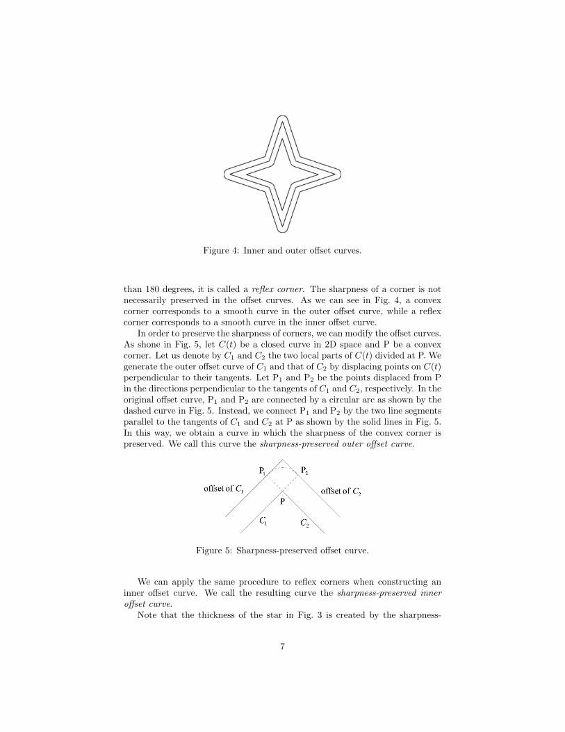
Figure 4: Inner and outer offset curves.
than 180 degrees, it is called a reflex corner. The sharpness of a corner is notnecessarily preserved in the offset curves. As we can see in Fig. 4, a convexcorner corresponds to a smooth curve in the outer offset curve, while a reflexcorner corresponds to a smooth curve in the inner offset curve.
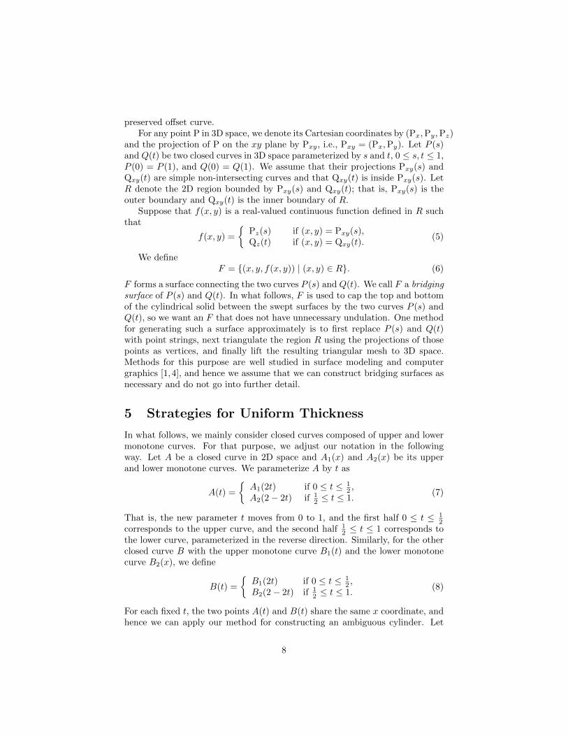
In order to preserve the sharpness of corners, we can modify the offset curves.As shone in Fig. 5, let C(t) be a closed curve in 2D space and P be a convexcorner. Let us denote by C1 and C2 the two local parts of C(t) divided at P. Wegenerate the outer offset curve of C1 and that of C2 by displacing points on C(t)perpendicular to their tangents. Let P1 and P2 be the points displaced from Pin the directions perpendicular to the tangents of C1 and C2, respectively. In theoriginal offset curve, P1 and P2 are connected by a circular arc as shown by thedashed curve in Fig. 5. Instead, we connect P1 and P2 by the two line segmentsparallel to the tangents of C1 and C2 at P as shown by the solid lines in Fig. 5.In this way, we obtain a curve in which the sharpness of the convex corner ispreserved. We call this curve the sharpness-preserved outer offset curve.
Figure 5: Sharpness-preserved offset curve.
We can apply the same procedure to reflex corners when constructing aninner offset curve. We call the resulting curve the sharpness-preserved inneroffset curve.
Note that the thickness of the star in Fig. 3 is created by the sharpness-
7
preserved offset curve.For any point P in 3D space, we denote its Cartesian coordinates by (Px,Py,Pz)
and the projection of P on the xy plane by Pxy, i.e., Pxy = (Px,Py). Let P (s)and Q(t) be two closed curves in 3D space parameterized by s and t, 0 ≤ s, t ≤ 1,P (0) = P (1), and Q(0) = Q(1). We assume that their projections Pxy(s) andQxy(t) are simple non-intersecting curves and that Qxy(t) is inside Pxy(s). LetR denote the 2D region bounded by Pxy(s) and Qxy(t); that is, Pxy(s) is theouter boundary and Qxy(t) is the inner boundary of R.
Suppose that f(x, y) is a real-valued continuous function defined in R suchthat
f(x, y) =
{Pz(s) if (x, y) = Pxy(s),Qz(t) if (x, y) = Qxy(t).
(5)
We defineF = {(x, y, f(x, y)) | (x, y) ∈ R}. (6)
F forms a surface connecting the two curves P (s) and Q(t). We call F a bridgingsurface of P (s) and Q(t). In what follows, F is used to cap the top and bottomof the cylindrical solid between the swept surfaces by the two curves P (s) andQ(t), so we want an F that does not have unnecessary undulation. One methodfor generating such a surface approximately is to first replace P (s) and Q(t)with point strings, next triangulate the region R using the projections of thosepoints as vertices, and finally lift the resulting triangular mesh to 3D space.Methods for this purpose are well studied in surface modeling and computergraphics [1,4], and hence we assume that we can construct bridging surfaces asnecessary and do not go into further detail.
5 Strategies for Uniform Thickness
In what follows, we mainly consider closed curves composed of upper and lowermonotone curves. For that purpose, we adjust our notation in the followingway. Let A be a closed curve in 2D space and A1(x) and A2(x) be its upperand lower monotone curves. We parameterize A by t as
A(t) =
{A1(2t) if 0 ≤ t ≤ 1
2 ,A2(2− 2t) if 1
2 ≤ t ≤ 1.(7)
That is, the new parameter t moves from 0 to 1, and the first half 0 ≤ t ≤ 12
corresponds to the upper curve, and the second half 12 ≤ t ≤ 1 corresponds to
the lower curve, parameterized in the reverse direction. Similarly, for the otherclosed curve B with the upper monotone curve B1(t) and the lower monotonecurve B2(x), we define
B(t) =
{B1(2t) if 0 ≤ t ≤ 1
2 ,B2(2− 2t) if 1
2 ≤ t ≤ 1.(8)
For each fixed t, the two points A(t) and B(t) share the same x coordinate, andhence we can apply our method for constructing an ambiguous cylinder. Let
8

C(t), 0 ≤ t ≤ 1, be the closed ambiguous curve constructed from A(t) and B(t),and S be the cylindrical surface defined by
S = {C(t)− uez | 0 ≤ t ≤ 1, 0 ≤ u ≤ h}. (9)
Our basic idea for generating an ambiguous cylinder with uniform thicknessis as follows. We first create another pair of closed curves A′(t) and B′(t) insideor outside A(t) and B(t) so that A(t) and A′(t) give uniform thickness to thefirst shape and B(t) and B′(t) give uniform thickness to the second shape, andthat the leftmost points of A′(t) and B′(t) share the same x coordinate, andthe rightmost points of A′(t) and B′(t) also share the same x coordinate. Nextwe construct the ambiguous space curve C ′(t) from A′(t) and B′(t), and theassociated cylindrical surface
S′ = {C ′(t)− uez | 0 ≤ t ≤ 1, 0 ≤ u ≤ h}. (10)
Finally, we pack material between S and S′, and thus obtain a solid cylinderwith finite thickness. These steps can be represented formally as the followingalgorithm.
Basic algorithm for adding thicknessInput: two closed curves A(t) and B(t), thickness parameter l, and height h.Procedure:Step 1. Create closed curves A′(t) and B′(t) inside or outside A(t) and B(t),
respectively.Step 2. Construct the ambiguous space curve C(t) from A(t) and B(t).Step 3. Construct the ambiguous space curve C ′(t) from A′(t) and B′(t).Step 4. Generate bridging surface F of C(t) and C ′(t).Step 5. Generate cylindrical solid D by
D = {P− uez | P ∈ F, 0 ≤ u ≤ h}. (11)
The set D of points defined in (11) is the volume swept by the bridging surfaceF in the direction parallel to the z axis by length h. Hence, it is equivalent tothe volume obtained by packing material between the two cylindrical surfacesS and S′ defined by (9) and (10).
Note that there is freedom in the choice of A′(t) and B′(t) in Step 1, butonce A′(t) and B′(t) are set, Steps 2 to 5 are performed without ambiguity.Hence we concentrate on Step 1. Note also that the input parameter l doesnot appear in the above procedure, but we will use this parameter in Step 1 asdescribed in what follows.
Our first strategy is to use the outer offset curves. Let A′(t) and B′(t) be theouter offset curves of A(t) and B(t), respectively, by l. Note that the rightmostpoint and the leftmost point of a closed curve are each either a smooth point or aconvex corner. Therefore, the horizontal distance between A(t) and A′(t) at therightmost or leftmost point is the same as l. The same is true of the horizontal
9
distance between B(t) and B′(t). Hence, the horizontal widths of A′(t) andB′(t) are the same, and a one-to-one correspondence can be established betweenA′(t) and B′(t). Consequently, we can construct the associated ambiguous curveC ′(t). Thus, we have the following strategy.
Strategy 1 (fattening strategy)Step 1-1. Construct the outer offset curve A′(t) of A(t) by l, and the outer offset
curve B′(t) of B(t) by l.
This strategy gives two appearances with uniform thickness in the sense thatthe thickness is determined by the original curves and their outer offset curves.However, this thickness is a little different from our intuitive idea of uniformnessbecause the sharpness of convex corners is lost.
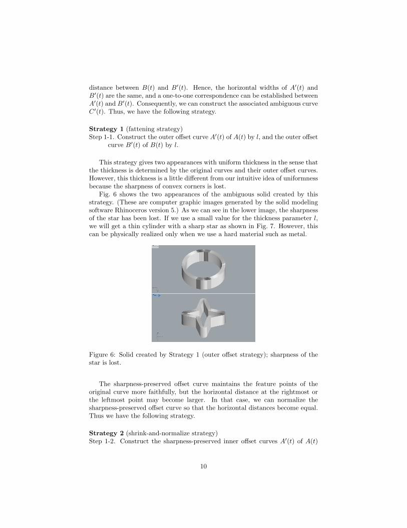
Fig. 6 shows the two appearances of the ambiguous solid created by thisstrategy. (These are computer graphic images generated by the solid modelingsoftware Rhinoceros version 5.) As we can see in the lower image, the sharpnessof the star has been lost. If we use a small value for the thickness parameter l,we will get a thin cylinder with a sharp star as shown in Fig. 7. However, thiscan be physically realized only when we use a hard material such as metal.
Figure 6: Solid created by Strategy 1 (outer offset strategy); sharpness of thestar is lost.
The sharpness-preserved offset curve maintains the feature points of theoriginal curve more faithfully, but the horizontal distance at the rightmost orthe leftmost point may become larger. In that case, we can normalize thesharpness-preserved offset curve so that the horizontal distances become equal.Thus we have the following strategy.
Strategy 2 (shrink-and-normalize strategy)Step 1-2. Construct the sharpness-preserved inner offset curves A′(t) of A(t)
10

Figure 7: Thin solid created by Strategy 1 (outer offset strategy); it will befragile unless made of a hard material.
by h, and the sharpness-preserved inner offset curves B′(t) of B(t) by h.Then, expand or shrink the curve B′(t) in such a way that the leftmostand the rightmost points share the same x coordinates as A′(t)
Fig. 8 shows the two appearances of the ambiguous solid created by thisstrategy. We can see that each shape has uniform thickness and that sharpcorners are preserved. However, the two shapes do not have the same thickness:the star is thinner than the full moon.
Figure 8: Solid created by Strategy 2 (horizontal width normalization strategy);the star is thinner than the full moon.
We should note that this strategy does not always work. An example isshown in Fig. 9. Suppose that the given curve and the sharpness-preserved inner
11

offset are as shown in (a). Because the horizontal thickness at the rightmostcorner is large, the normalized inner curve becomes the dashed line in (b), whichintersects with the original curve. Hence, the desired ambiguous solid cannotbe created.
(a) (b)
Figure 9: Example in which Strategy 2 does not work: (a) original curve andits inner offset curve; (b) normalized inner curve which intersects the originalcurve.
Another strategy for making the horizontal widths of the two curves A′(t)and B′(t) the same is to add horizontal line segments as shown in Fig. 10, whichis based on the same pair of curves as before, i.e., a full moon A(t) and a starB(t). As shown, we let A1(t) and A2(t) [resp. B1(t) and B2(t)] be the upperand lower monotone curves of A(t) [resp. B(t)], and let A′
1(t) and A′2(t) [resp.
B′1(t) and B′
2(t)] be the inner offset curves of A1(t) and A2(t) [resp. B1(t) andB2(t)] by l.
Because B(t) has sharp corners at the rightmost and leftmost points, thehorizontal width of the inner offset curve of B(t) is smaller than that of A(t).Instead of expanding it, we add horizontal line segment, say Bl and Br, to theleft and to the right of the offset curves so that the horizontal width becomesthe same as that of the other offset curve A′(t). In other words, we augmentB′
1(t) and B′2(t) by adding Bl to the left and Br to the right. Then, the resulting
horizontal widths are the same as those of A′1(t) and A′
2(t), and hence we haveone-to-one correspondences between A′
1(t) and B′1(t), and between A′
2(t) andB′
2(t), enabling us to apply the method of ambiguous cylinder construction.Thus, we have the following strategy.
Strategy 3 (shrink-and-augment strategy)Step 1-3. Construct the sharpness-preserved inner offset curves A′(t) of A(t)
12
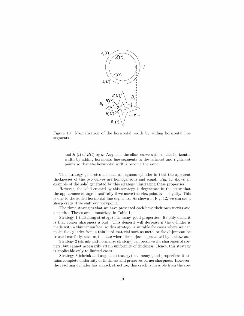
Figure 10: Normalization of the horizontal width by adding horizontal linesegments.
and B′(t) of B(t) by h. Augment the offset curve with smaller horizontalwidth by adding horizontal line segments to the leftmost and rightmostpoints so that the horizontal widths become the same.
This strategy generates an ideal ambiguous cylinder in that the apparentthicknesses of the two curves are homogeneous and equal. Fig. 11 shows anexample of the solid generated by this strategy illustrating these properties.
However, the solid created by this strategy is degenerate in the sense thatthe appearance changes drastically if we move the viewpoint even slightly. Thisis due to the added horizontal line segments. As shown in Fig. 12, we can see asharp crack if we shift our viewpoint.
The three strategies that we have presented each have their own merits anddemerits. Theses are summarized in Table 1.
Strategy 1 (fattening strategy) has many good properties. Its only demeritis that corner sharpness is lost. This demerit will decrease if the cylinder ismade with a thinner surface, so this strategy is suitable for cases where we canmake the cylinder from a thin hard material such as metal or the object can betreated carefully, such as the case where the object is protected by a showcase.
Strategy 2 (shrink-and-normalize strategy) can preserve the sharpness of cor-ners, but cannot necessarily attain uniformity of thickness. Hence, this strategyis applicable only to limited cases.
Strategy 3 (shrink-and-augment strategy) has many good properties: it at-tains complete uniformity of thickness and preserves corner sharpness. However,the resulting cylinder has a crack structure; this crack is invisible from the cor-
13
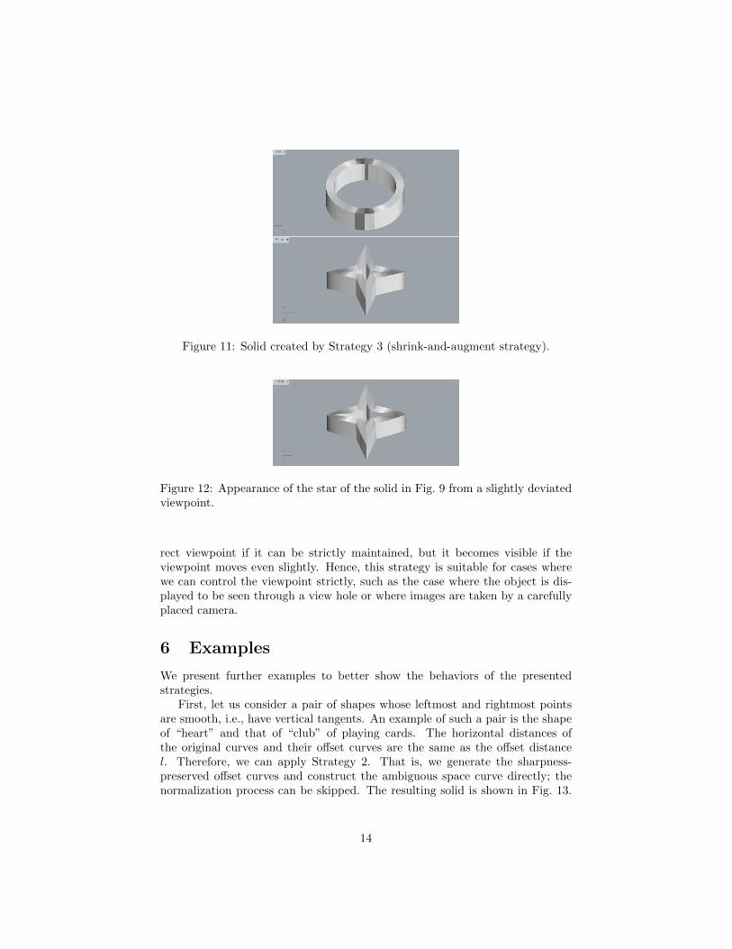
Figure 11: Solid created by Strategy 3 (shrink-and-augment strategy).
Figure 12: Appearance of the star of the solid in Fig. 9 from a slightly deviatedviewpoint.
rect viewpoint if it can be strictly maintained, but it becomes visible if theviewpoint moves even slightly. Hence, this strategy is suitable for cases wherewe can control the viewpoint strictly, such as the case where the object is dis-played to be seen through a view hole or where images are taken by a carefullyplaced camera.
6 Examples
We present further examples to better show the behaviors of the presentedstrategies.
First, let us consider a pair of shapes whose leftmost and rightmost pointsare smooth, i.e., have vertical tangents. An example of such a pair is the shapeof “heart” and that of “club” of playing cards. The horizontal distances ofthe original curves and their offset curves are the same as the offset distancel. Therefore, we can apply Strategy 2. That is, we generate the sharpness-preserved offset curves and construct the ambiguous space curve directly; thenormalization process can be skipped. The resulting solid is shown in Fig. 13.
14

Table 1: Comparison of the three strategies
Property 1. Fattening 2. Shrink-and- 3. Shrink-and-strategy normalize strategy augment strategy
(i) Each appearance has YES NO YESuniform thickness
(ii) Two appearances have YES NO YESthe same thickness
(iii) Sharp corners are NO YES YESpreserved
(iv) Applicable to any YES NO YESshapes
(v) Stable against YES YES NOviewpoint deviation
We can see that the two appearances have the same uniform thickness. Thus,Strategy 2 works well if both of the shapes have smooth leftmost and rightmostpoints.
Figure 13: “Heart” and “club”; in both shapes, the leftmost and rightmostpoints are smooth points, and hence Strategy 2 can be applied directly.
The next example is a pair of dolls whose heads are on the right and onthe left. Applying Strategy 1, we obtain the cylinder whose two appearancesare as shown in Fig. 14. Uniformity of thickness is attained, but the apex atthe legs is lost. If we apply Strategy 2, the normalized inner curve is displacedfrom the center, as shown in the lower diagram in Fig. 15, and consequentlythe thickness becomes non-uniform. The resulting solid will be as shown inFig. 16. If we apply Strategy 3, on the other hand, we can construct a solidwhose two appearances have the same uniform thickness, as shown in Fig. 17.
15

However, this solid has a crack around the apex at the legs, which can be seenif we slightly move our viewpoint, as shown in Fig. 18. Hence, Strategy 1 seemsmost suitable for this pair of shapes if we want to place the solid in a museumfor exhibition.
Figure 14: Left-oriented and right-oriented dolls generated by Strategy 1; thesharpness of the corner is lost.
Figure 15: Normalization of the horizontal width according to Strategy 2.
Next, let us consider the pair of shapes shown in Fig. 19(a): a circle anda triangle-like closed curve. Our plan is to combine the ambiguous cylindergenerated by this pair of shapes and its mirrored and/or rotated copies to formthe crossing leaves shown in (b).
Fig. 20 shows the unit ambiguous cylinders generated by the three strategies.Strategy 1 results in (a), which seems to have good appearances if we see thisunit alone. Strategy 2 results in (b), which is not of good quality becausethe thickness is not uniform: the leftmost edge is wider than the other twoedges. Strategy 3 results in (c), which preserves sharp corners but has unstableappearances because the cylinder has a small crack at the right corner, as shown
16
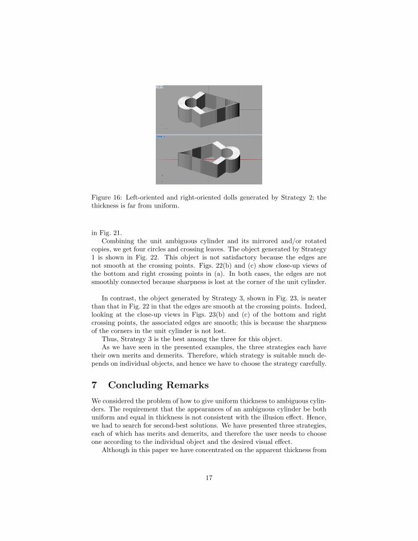
Figure 16: Left-oriented and right-oriented dolls generated by Strategy 2; thethickness is far from uniform.
in Fig. 21.Combining the unit ambiguous cylinder and its mirrored and/or rotated
copies, we get four circles and crossing leaves. The object generated by Strategy1 is shown in Fig. 22. This object is not satisfactory because the edges arenot smooth at the crossing points. Figs. 22(b) and (c) show close-up views ofthe bottom and right crossing points in (a). In both cases, the edges are notsmoothly connected because sharpness is lost at the corner of the unit cylinder.
In contrast, the object generated by Strategy 3, shown in Fig. 23, is neaterthan that in Fig. 22 in that the edges are smooth at the crossing points. Indeed,looking at the close-up views in Figs. 23(b) and (c) of the bottom and rightcrossing points, the associated edges are smooth; this is because the sharpnessof the corners in the unit cylinder is not lost.
Thus, Strategy 3 is the best among the three for this object.As we have seen in the presented examples, the three strategies each have
their own merits and demerits. Therefore, which strategy is suitable much de-pends on individual objects, and hence we have to choose the strategy carefully.
7 Concluding Remarks
We considered the problem of how to give uniform thickness to ambiguous cylin-ders. The requirement that the appearances of an ambiguous cylinder be bothuniform and equal in thickness is not consistent with the illusion effect. Hence,we had to search for second-best solutions. We have presented three strategies,each of which has merits and demerits, and therefore the user needs to chooseone according to the individual object and the desired visual effect.
Although in this paper we have concentrated on the apparent thickness from
17
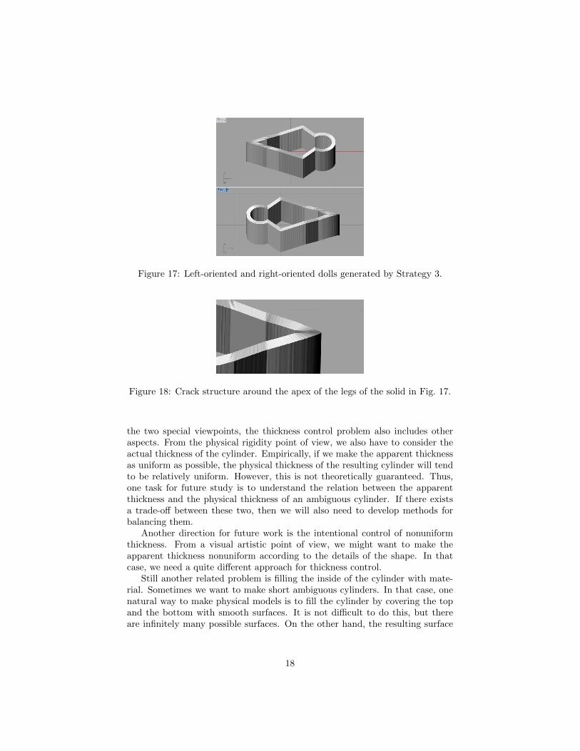
Figure 17: Left-oriented and right-oriented dolls generated by Strategy 3.
Figure 18: Crack structure around the apex of the legs of the solid in Fig. 17.
the two special viewpoints, the thickness control problem also includes otheraspects. From the physical rigidity point of view, we also have to consider theactual thickness of the cylinder. Empirically, if we make the apparent thicknessas uniform as possible, the physical thickness of the resulting cylinder will tendto be relatively uniform. However, this is not theoretically guaranteed. Thus,one task for future study is to understand the relation between the apparentthickness and the physical thickness of an ambiguous cylinder. If there existsa trade-off between these two, then we will also need to develop methods forbalancing them.
Another direction for future work is the intentional control of nonuniformthickness. From a visual artistic point of view, we might want to make theapparent thickness nonuniform according to the details of the shape. In thatcase, we need a quite different approach for thickness control.
Still another related problem is filling the inside of the cylinder with mate-rial. Sometimes we want to make short ambiguous cylinders. In that case, onenatural way to make physical models is to fill the cylinder by covering the topand the bottom with smooth surfaces. It is not difficult to do this, but thereare infinitely many possible surfaces. On the other hand, the resulting surface
18

(a) (b)
Figure 19: Four circles and crossing leaves: (a) unit pair of shapes; (b) fourcircles and crossing leaves created by combination of (a) and its mirrored and/orrotated copies.
(a) (b) (c)
Figure 20: Unit ambiguous cylinders generated by three strategies: (a) Strategy1; (b) Strategy 2; (c) Strategy 3.
creates shading effects, and different surfaces give different shading and conse-quently give different visual effects, so we need to find the smooth surface suchthat the resulting shading enhances (or at least does not diminish) the visualeffect of the ambiguous cylinder.
References
[1] G. Farin: Curves and Surfaces for CAGD: A Practical Guide. Fourth Edi-tion, Academic Press, San Diego, 1988.
[2] R. T. Farouki and C. A. Neff: Analytic properties of plane offset curves.Computer Aided Geometric Design, 7 (1990), 83–99.
19

Figure 21: Crack created by Strategy 3.
(a) (b) (c)
Figure 22: Four circles and crossing leaves generated by Strategy 1: (a) fullview of appearance; (b) close-up view of the bottom crossing point; (c) close-upview of the right crossing point.
[3] R. L. Gregory: The Intelligent Eye. Weidenfeld & Nicolson, London, 1970.
[4] J. Gomes, L. Darsa, B. Costa and L. Velho: Wrapping and Morphing ofGraphical Objects. Morgan Kaufmann Publisher Inc., San Francisco, 1999.
[5] J. Hoschek: Offset curves in the plane. Computer-Aided Design, 17 (1985),77–82.
[6] E. M. Hundert: Lessons from an Optical Illusion. Harvard University Press,Cambridge, Massachusetts, 1995.
[7] J. Ninio: The Science of Illusions. Cornell University Press, Ithaca, 2001.
[8] L. S. Penrose and R. Penrose: Impossible objects: A special type of visualillusion. British Journal of Psychology, 49 (1958), 31–33.
[9] D. N. Perkins: Visual discrimination between rectangular and nonrectan-gular parallelopipeds. Perception & Psychophysics, 12 (1972), 396–400.
[10] J. O. Robinson: The Psychology of Visual Illusion. Dover Publications,Inc., Mineola, New York, 1998.
20

(a) (b) (c)
Figure 23: Four circles and crossing leaves generated by Strategy 3: (a) fullview of appearance; (b) close-up view of the bottom crossing point; (c) close-upview of the right crossing point.
[11] A. Seckel: The Ultimate Book of Optical Illusions. Sterling, New York,2005.
[12] K. Sugihara: Machine Interpretation of Line Drawings. The MIT Press,Cambridge, 1986.
[13] K. Sugihara: Three-dimensional realization of anomalous pictures — Anapplication of picture interpretation theory to toy design. Pattern Recogni-tion, 30 (1997), 1061–1067.
[14] K. Sugihara: Design of solids for antigravity motion illusion. ComputationalGeometry: Theory and Applications, 47 (2014), 675–682.
[15] K. Sugihara: Ambiguous cylinders: A new class of impossible objects.Computer Aided Drafting, Design and Manufacturing, 25 (2015), no. 3,19–25.
[16] K. Sugihara: A new type of impossible objects that become partly invisi-ble in a mirror. Japan Journal of Industrial and Applied Mathematics, 33(2016), 525–535.
[17] N. J. Wade and P. Hughes: Fooling the eyes: Trompe l’œil and reverseperspective. Perception, 28 (1999), 1115–1119.
21