Thin film delamination under in-plane residual stresses · PDF fileLoughborough University Institutional Repository Thin film delamination under in-plane residual stresses This item
This item was submitted to Loughborough University's Institutional Repositoryby the/an author.
Citation: HARVEY, C.M. and WANG, S., 2016. Thin film delaminationunder in-plane residual stresses. Presented at the 2nd International Conferenceon Mechanics of Composites, Universidade do Porto, July 11-14th.
Additional Information:
• This is a powerpoint presentation entitled ``Thin Film Cracking'' whichwas presented at 2nd International Conference on Mechanics of Com-posites. The abstracts of the papers delivered at the conference werepublished in: Antonio J.M. Ferreira ...et al. (eds.) 2nd InternationalConference on Mechanics of Composites, Universidade do Porto, July 11-14th, Bologna: Societ�a Editrice Esculapio, 2016. ISBN 9788874889631ISSN 2421-2822.
Rights: This work is made available according to the conditions of the Cre-ative Commons Attribution-NonCommercial-NoDerivatives 4.0 International(CC BY-NC-ND 4.0) licence. Full details of this licence are available at:https://creativecommons.org/licenses/by-nc-nd/4.0/
2nd International Conference on Mechanics of Composites
Department of Aeronautical and Automotive Engineering Loughborough University, UK
Presenter
Presentation Notes
Hello, my name is … I’m here with my colleague SW We’re both here from Loughborough University in the UK And we’d like to welcome you to our presentation on our recent work on the cracking of thin films
Agenda Part 1 (15 min) 1. Introduction 2. Partition of mixed-mode cracks 3. Macroscopic fracture 4. Thin film delamination Part 2 (15 min) 5. Room temperature α-alumina spallation
2
Presenter
Presentation Notes
You’ll notice from that schedule that we have two consecutive presentations As the 2nd presentation builds on the 1st, we have decided to give both presentations in one continuous presentation with two parts, each of around 15 minutes In the first part, I will describe the background and theory of a general mechanical fracture model developed at Loughborough University, and its application to thin-film problems. In the second part, the spallation of α-alumina films on thick substrates is considered, and the mechanical model is used to make predictions about the cracking behaviour, which are then compared to experimental results from the literature.
Introduction • Thin solid films are found in a variety of applications:
– E.g. Electronic semiconductors; Thermal barrier coatings (TBCs); Surface protection against corrosion, friction and wear
• Not usually expected to have primary load-carrying capability • But residual stresses are often present due to the fabrication
process and working conditions: – E.g. Mismatch of thermal expansion coefficients in TBCs
• A major cause of film cracks and debonding – E.g. Buckling-driven delamination
• Fracture toughness is mode partition-dependent
3
Presenter
Presentation Notes
The subject of this presentation, namely, the cracking of thin films, is an important one as thin films are found in a variety of applications. - For example, in semiconductors, TBCs, and in surface coatings for protection… Films are not usually primary load-bearing structures, however, residual stresses often do occur in films due to the fabrication process and the operating conditions. For example, for TBC layered material systems in gas turbine engines, the mismatch of thermal expansion coefficient between adjacent layers can cause very high residual stresses in each layer of the system due to cooling. Residual stresses in thin films are a major cause of cracks and debonding. Buckling-driven delamination is a typical example of film failure under in-plane compressive residual stress, which has been studied extensively during the last few decades. The mechanical modelling of residual stresses is in itself not too complex a problem. However, the resistance against fracture, that is, the fracture toughness, which controls the cracking process, is not purely an intrinsic material property, but also depends on the fracture mode partition, or the relative contributions of mode I opening, mode II shearing and mode III tearing. For this reason, we treat the cracking of thin films primarily as a mixed-mode fracture problem. Images: Zhou & Hashida (2002), ASME 124:922-930, Kanatzidis (2004), Nature 428:269-271 (http://www.nature.com/nature/journal/v428/n6980/fig_tab/428269a_F1.html) http://www.qtmi.net/a-marriage-thick-films-and-thin-films/
Aim • To develop an analytical mechanical model to
predict the cracking behaviour of thin films.
4
Presenter
Presentation Notes
The first aim of this work was therefore to accurately predict fracture mode partition in order to predict the mode-dependent fracture toughness. The overall aim, however, was to use the mixed-mode fracture model to develop an analytical mechanical model to predict the cracking behaviour of thin films.
General methodology
Authors’ existing theory
for mixed-mode
interfacial fracture
Applied to thin films
Mechanical modelling of
problem
Crack tip loads determine: •Fracture mode-dependent fracture energy
•Fracture mode-dependent fracture toughness
Prediction of cracking
behaviour
5
Presenter
Presentation Notes
To achieve the overall aim, this is an overview process that was used. A general theory of mixed-mode fracture has already been developed at Loughborough University. We started from this strong position. The theory is then reduced to thin films where the substrate becomes very thick in comparison to the film. Mechanical modelling of a thin film layer with a separation between the substrate and film subject to in-plane residual compressive stress provides the internal loads at the crack tip. Knowledge of the crack tip loads allows the mixed-mode fracture energy and the mixed-mode fracture toughness to be calculated. This then allows prediction of the cracking behaviour, because if fracture energy exceeds fracture toughness, a crack propagates.
Mixed-mode interfacial fracture • 1D fracture of DCB is
fundamental case for study – Bending moments 𝑀𝑀1 and 𝑀𝑀2 – Axial forces 𝑁𝑁1 and 𝑁𝑁2 – Shear forces 𝑃𝑃1 and 𝑃𝑃2 – 𝜂𝜂 = 𝐸𝐸2 𝐸𝐸1⁄ , Ν = 𝜈𝜈2 𝜈𝜈1⁄ , 𝛾𝛾 = ℎ2 ℎ1⁄
Double cantilever beam (DCB)
6
Presenter
Presentation Notes
The starting point, is the general theory of mixed-mode fracture, developed at Loughborough University. In my next few slides, I explain this theory and its capability in more detail. If we study the fundamental case of a DCB, we gain deep understanding and predictive capability for real life applications. And we are by no means restricted to a simple class of fracture problems. In the DCB case, we consider… BMs, AFs, SFs. ‘B’ denotes a crack tip quantity. And we also consider mismatch of Young’s modulus, mismatch of Poisson’s ratio, and different through-thickness crack locations.
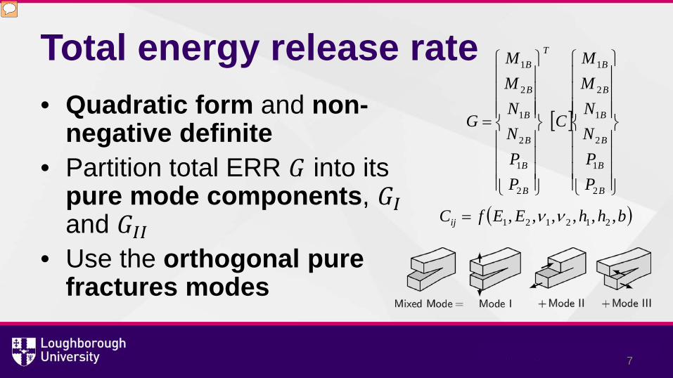
Total energy release rate • Quadratic form and non-
negative definite • Partition total ERR 𝐺𝐺 into its
pure mode components, 𝐺𝐺𝐼𝐼 and 𝐺𝐺𝐼𝐼𝐼𝐼
• Use the orthogonal pure fractures modes
[ ]
=
B
B
B
B
B
BT
B
B
B
B
B
B
PPNNMM
C
PPNNMM
G
2
1
2
1
2
1
2
1
2
1
2
1
( )bhhEEfCij ,,,,,, 212121 νν=
7
Presenter
Presentation Notes
Now the total ERR of the DCB can be calculated. It is identified that the ERR G is of quadratic form and is non-negative definite. An analogy of G is the kinetic energy of a vibrating structure, which can be partitioned into the energies of orthogonal natural vibration modes. We therefore get the idea to partition the ERR of a DCB into the energy of orthogonal pure fracture modes, representing fracture mode I, mode II and mode III, as shown.
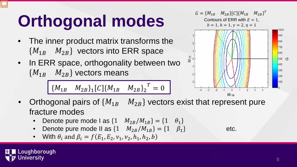
Orthogonal modes • The inner product matrix transforms the
𝑀𝑀1𝐵𝐵 𝑀𝑀2𝐵𝐵 vectors into ERR space • In ERR space, orthogonality between two
𝑀𝑀1𝐵𝐵 𝑀𝑀2𝐵𝐵 vectors means
𝑀𝑀1𝐵𝐵 𝑀𝑀2𝐵𝐵 1 𝐶𝐶 𝑀𝑀1𝐵𝐵 𝑀𝑀2𝐵𝐵 2𝑇𝑇 = 0
• Orthogonal pairs of 𝑀𝑀1𝐵𝐵 𝑀𝑀2𝐵𝐵 vectors exist that represent pure fracture modes
• Denote pure mode I as 1 𝑀𝑀2𝐵𝐵/𝑀𝑀1𝐵𝐵 = 1 𝜃𝜃1 • Denote pure mode II as 1 𝑀𝑀2𝐵𝐵/𝑀𝑀1𝐵𝐵 = 1 𝛽𝛽1 etc. • With 𝜃𝜃𝑖𝑖 and 𝛽𝛽𝑖𝑖 = 𝑓𝑓 𝐸𝐸1,𝐸𝐸2, 𝜈𝜈1, 𝜈𝜈2,ℎ1,ℎ2, 𝑏𝑏
8
Contours of ERR with 𝐸𝐸 = 1, 𝑏𝑏 = 1, ℎ = 1, 𝛾𝛾 = 2, 𝜂𝜂 = 1
𝐺𝐺 = 𝑀𝑀1𝐵𝐵 𝑀𝑀2𝐵𝐵 𝐶𝐶 𝑀𝑀1𝐵𝐵 𝑀𝑀2𝐵𝐵𝑇𝑇
Presenter
Presentation Notes
To explore this idea of orthogonal fracture modes further, consider only bending moments with no axial forces or shear forces, without any loss of generality. The total energy release rate is related to the applied bending moment vector, {M1B, M2B}. In Euclidean space, 2 vectors are orthogonal if their dot product is 0, that is, they make an angle of pi/2. However, the inner product matrix [C] in the total ERR equation, represents a transformation into energy release rate space, which can be visualised by examining contours of ERR against M1B and M2B. The graph shows just one arbitrary example of this. In ERR space, orthogonality between two {M1B M2B} vectors means that they satisfy this condition, and they do not generally make an angle of pi/2. The graph shows three orthogonal pairs of vectors in black, green and red. There are in fact an infinite number of orthogonal pairs. The task is to find which pair represents pure fracture modes. Let theta represent the gradient, M2B/M1B, where there pure mode I opening. Let beta represent the gradient, M2B/M1B, where there pure mode II opening. theta and beta can be determined by using the theory of elasticity. When the crack tip relative shearing displacement or crack tip shearing force is zero, then there is pure mode I. When the crack tip relative opening displacement or crack tip opening force is zero, then there is pure mode II. Naturally, the pure modes, theta and beta, depend on several parameters related to the material properties and the geometry.
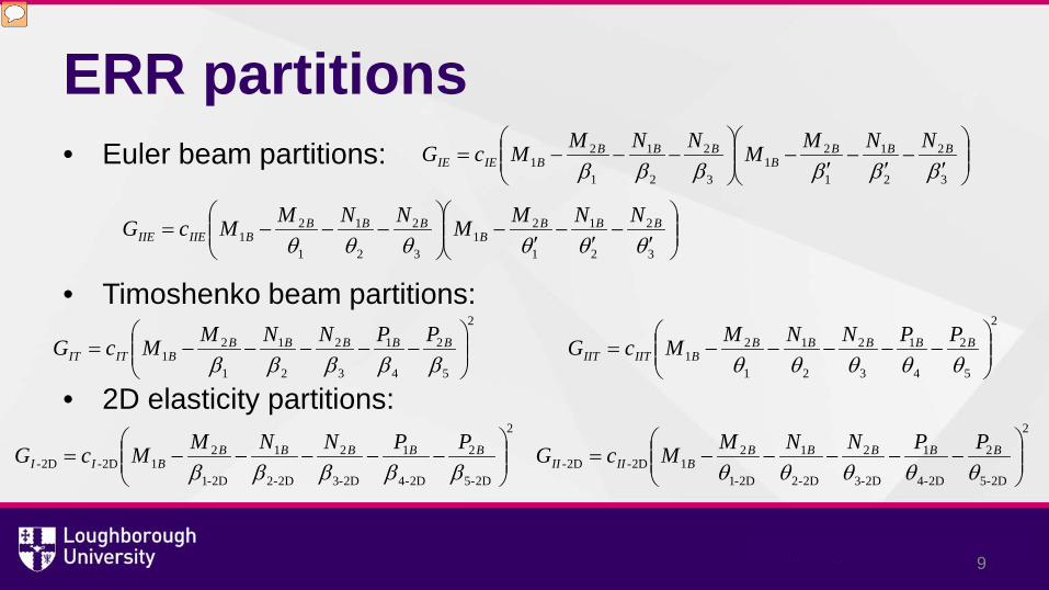
ERR partitions • Euler beam partitions:
• Timoshenko beam partitions:
• 2D elasticity partitions:
′
−′
−′
−
−−−=
3
2
2
1
1
21
3
2
2
1
1
21 ββββββ
BBBB
BBBBIEIE
NNMMNNMMcG
′
−′
−′
−
−−−=
3
2
2
1
1
21
3
2
2
1
1
21 θθθθθθ
BBBB
BBBBIIEIIE
NNMMNNMMcG
2
5
2
4
1
3
2
2
1
1
21
−−−−−=βββββ
BBBBBBITIT
PPNNMMcG2
5
2
4
1
3
2
2
1
1
21
−−−−−=θθθθθ
BBBBBBIITIIT
PPNNMMcG
2
2D-5
2
2D-4
1
2D-3
2
2D-2
1
2D-1
212D-2D-
−−−−−=βββββ
BBBBBBII
PPNNMMcG
9
2
2D-5
2
2D-4
1
2D-3
2
2D-2
1
2D-1
212D-2D-
−−−−−=θθθθθ
BBBBBBIIII
PPNNMMcG
Presenter
Presentation Notes
In fact, the pure fracture modes, have been determined at LU within the context of (1) Euler beam, or classical plate, theory, (2) Timoshenko beam theory, and (3) Full 2D elasticity. It should be noted that by using Loughborough theory, it is only necessary to find one pure mode, and then all the others can be derived by using the orthogonality condition. Euler theory gives 2 sets of pure modes, denoted by theta and theta’ for pure mode I, and by beta and beta’ for pure mode II. Timoshenko beam theory has only 1 set of pure modes, which are the same as the theta and beta modes from Euler theory. Finally, although 2D elasticity theory generally gives two sets of pure modes for the case of bimaterial mismatch and finite crack growth, when the mismatch is disregarded, it reduces to one set of pure modes which is between the two sets from Euler theory Therefore, by these equations, in all cases, when M2B = theta1 * M1B, using the respective value of theta1, and other loads are zero, we get pure mode I ERR as GII = 0.
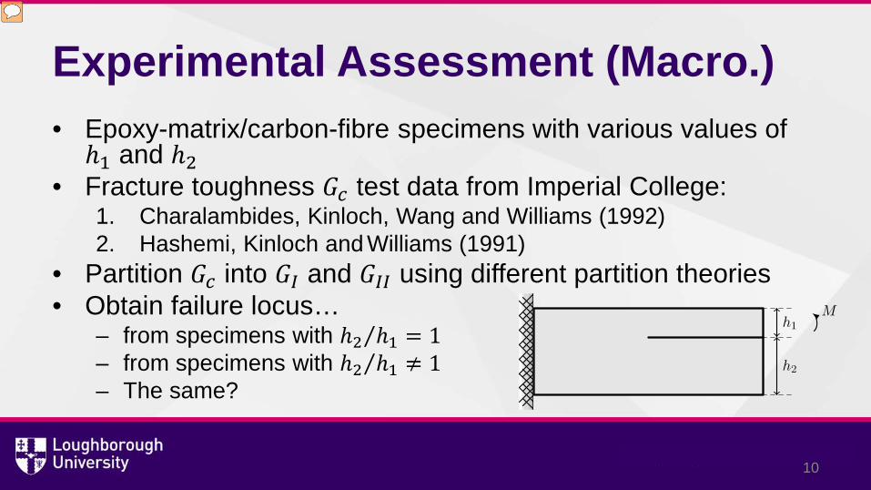
Experimental Assessment (Macro.) • Epoxy-matrix/carbon-fibre specimens with various values of ℎ1 and ℎ2
• Fracture toughness 𝐺𝐺𝑐𝑐 test data from Imperial College: 1. Charalambides, Kinloch, Wang and Williams (1992) 2. Hashemi, Kinloch and Williams (1991)
• Partition 𝐺𝐺𝑐𝑐 into 𝐺𝐺𝐼𝐼 and 𝐺𝐺𝐼𝐼𝐼𝐼 using different partition theories • Obtain failure locus…
– from specimens with ℎ2 ℎ1⁄ = 1 – from specimens with ℎ2 ℎ1⁄ ≠ 1 – The same?
10
Presenter
Presentation Notes
Which of these theories is the correct one to calculate the partition and to thereby predict the fracture toughness? In our previous work, we have taken fracture toughness data from two experimental programmes at Imperial College using a number of epoxy/carbon specimens with various through-thickness crack locations. Here we refer to these tests as ‘macro’ scale tests, in contrast to later tests with layers with thickness measured in micrometres, which are called ‘micro’ scale tests. By using specimens with a central through-thickness crack, where all theories in the literature unanimously agree on the partition, the failure locus of Gc vs. the partition is obtained. The correct partition theory should then produce the same failure locus for cracks at different through-thickness locations.
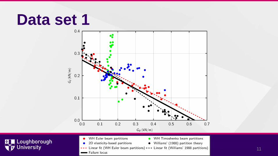
Data set 1
11
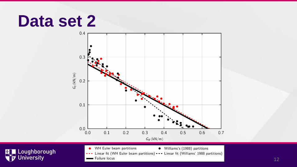
Data set 2
12
Observations from ‘macro.’ tests • Only two partition theories are close to failure locus:
– WH Euler beam theory – Williams’ (1988) theory
• 2D elasticity-based partitions are far from failure locus • WH Timoshenko partitions are very far from failure locus
• WH Euler beam partitions are closest to the failure locus
13
Conclusions from ‘macro.’ tests • WH Euler beam partition theory governs propagation of brittle interface
fracture • Seems in contradiction to ‘common sense’ • An infinitesimal crack growth is assumed in the theories • But crack extension develops over a finite-size distance • WH Euler beam partition theory is insensitive to the growth size
– It captures ‘finite small growth’ physics very well – Is also called the ‘global partition theory’
• 2D elasticity-based partitions approach WH Euler beam partitions when growth size is increased
14
Thin films • Reduce 2D elasticity-based partition theory
– Thin layer of thickness ℎ – and effective Young’s modulus 𝐸𝐸� (neglect material mismatch)
• Mode I and II ERRs take the following form:
• 𝑀𝑀𝐵𝐵𝐵𝐵 , 𝑁𝑁𝐵𝐵𝐵𝐵 and 𝑃𝑃𝐵𝐵𝐵𝐵 are the effective crack tip bending moment, in-plane force and shear force in the film.
15
2
2D-432D- 450.4
66227.0
−−×=β
BeBeBeI
PhNMhE
G2
2D-432D- 697.2
63773.0
−+×=θ
BeBeBeII
PhNMhE
G
Thick substrate
Presenter
Presentation Notes
Effective load is the residual load and the crack tip concentrated load