thin gripper - intelligent actuator
TRANSCRIPT

www.intelligentactuator.com
Thin Gripper RCP6-GRT7Equipped with a Battery-less Absolute Encoder

With orthogonal axis + gripper pick and place, all axes can be configured with battery-less absolute encoder equipped products. Home return is no longer required when restarting the equipment; you can move to the next operation while gripping the workpiece.
By adopting an integrated body frame guide with proven performance for linear axes, the gripping point distance and overhang amount have been improved greatly.
The height has been reduced.
Model GRT7A GRT7B
TypeHigh
speed type
High speed type
High grip force type
Maximum grip force
(Fingers onboth sides)
120N 150N 300N
IAI presents our highest-class grip force. (Current limit value 70%)
* For push holding, the push status is not retained.
Equipped with a Battery-less Absolute Encoder as Standard
High Rigidity
Flat Shape with Height of 39 mm
80mm
60mm
40mm
20mm
0mm
RCP4-GRSML (Stroke 14)
RCP2-GRST (Stroke 40)
RCP6-GRT7A/7B (Stroke 30/40/80)
1Advantage
2Advantage
3Advantage
High Grip Force4Advantage
87.5mm
39mm
55% reduction
Gothic arch groove
Steel ball[Maximum overhang amount]
90mm
150mmRCP6-GRT7B
Conventional model
New
New
(At current limit value 30%)
It remembers the position even after Shutdown --> Restart.It retains the grip.
Power Shutdown
Restart
Gripper First!New Type Equipped with Battery-less Absolute Encoder!!Flat shape, thin size with height of 39 mm achieved.
1

4-side mounting (including mounting on the finger operation surface), wiring exit direction and surface can be changed. Select the mounting/wiring position according to the equipment.
Compared with our products with equivalent stroke, it is 39% cheaper.
RCP6 - - - - - - - -WA 28P
¢ Mounting surface
RCP2-GRST(40ST)
RCP6-GRT7B(40ST)
Series Type Encoder Type Motor Size Deceleration Ratio Pattern
Stroke Cable Length OptionsApplicable Controllers
Model Specification Items
Improved Mounting Freedom5Advantage
Inexpensive6Advantage
About 39% reduction
Top
Back
Rear
Front
¢ Wiring exit direction Conventional model
GRT7A
GRT7B
N None
P 1m
S 3m
M 5m
X££ Specified length
R££ Robot cable
AC1 Actuator’s pigtail cable: 1m
AC2 Actuator’s pigtail cable: 2m
AC3 Actuator’s pigtail cable: 3m
CJTB Rear cable exit from top
CJLB Rear cable exit from left side
CJRB Rear cable exit from right side
CJBB Rear cable exit from bottom
CJTS Side cable exit from top
CJLS Side cable exit from left side
CJRS Side cable exit from right side
CJBS Side cable exit from bottom
NM Non-motor end specification
WA Battery-less Absolute
28P £28 Pulse motor
1
Feed screw lead 1.5mm Pulley deceleration ratio 1.5 (GRT7A)
Feed screw lead 2mm Pulley deceleration ratio 1.25 (GRT7B)
2 Feed screw lead 2mm Pulley deceleration ratio 2.5 (GRT7B)
30 30mm (15mm on one side)
40 40mm (20mm on one side)
80 80mm (40mm on one side)
P3
PCON-CB/CGB
PCON-CYB/PLB/POB
MCON-C/CG/LC/LCG
MSEL-PC/PG
P5 RCM-P6PC
New
(Finger operation surface)
2

3 RCP6-GRT7A
RCP6 ROBO Cylinder®
RCP6-GRT7A¢ Model
Specification Items
Thin Slide Type
2-Finger Gripper
Grip
forc
e (N
)
00 10 20
Current limit value (Ratio %)* Grip force is the sum of both fingers
30 40 50 60 8070
20406080
100120140
28P: Stepper Motor 28£ Size
WA: Battery-less Absolute
N: NoneP: 1mS: 3m
M: 5mX ££: Specified Length
Please refer to the option price list below.
* Be sure to fill in one of the following options for the cable exit direction.
30: 30mm1: Feed Screw Lead 1.5mm Pulley Deceleration Ratio 1.5
Legend: ① Applicable Controllers ② Cable Length ③Options (Unit: mm/s)
Actuator Specifications¢ Stroke and Max Opening/Closing Speed
Stroke
Deceleration ratio30
(mm)
1
* Please note that, when gripping (pushing), the speed is fixed at 5 mm/s.
RCP6-GRT7A-WA-28P-1-30-① -② -③ 1 120 (one side 60)
30 (one side 15) 75
* The gripping force graph above shows numbers for reference. Please allow margins up to ±15%.
¢ Gripping Force vs. Electric Current Limit The gripping (pushing) force can be adjusted freely within the range of electric current limits of 20% to 70%.
(1) The maximum opening/closing speed indicates the operating speed on one side. The relative operating speed is twice this value.
(2) The maximum gripping force is the sum of the gripping forces of both fingers, at a gripping point where there is no offset or overhang distance. The workpiece weight that can be actually moved depends on the friction coefficient between the gripper fingers and the workpiece, as well as on the shape of the workpiece. As a rough guide, a workpiece 's weight should not exceed 1/10 to 1/20 of the gripping force. (See page 9 for details.)
(3) The rated acceleration while moving is 0.3 G.
P3: PCON MCON MSEL
P5: RCM-P6PC* Does not include a controller.* Please refer to P.2 for more information about the model specification items.
③Options
* Be sure to select a symbol for the cable exit direction.
Name Option code Reference pageActuator's pigtail cable 1m specification AC1 P. 8Actuator's pigtail cable 2m specification AC2 P. 8Actuator's pigtail cable 3m specification AC3 P. 8Rear cable exit from top C JTB P. 8Rear cable exit from left side C JLB P. 8Rear cable exit from right side C JRB P. 8Rear cable exit from bottom C JBB P. 8Side cable exit from top C JTS P. 8Side cable exit from left side C JLS P. 8Side cable exit from right side C JRS P. 8Side cable exit from bottom C JBS P. 8Non-motor end specification NM P. 8
Actuator Specifications
ItemTiming belt + left/right trapezoidal screw f8±0.01mmOne side 0.2mm or lessOne side 0.2mm or lessMa: 3.6N·m Mb: 3.6N·m Mc: 10.2N·m0.46kg0~40°C, 85% RH or less (non-condensing)
L2
L1
② Cable Length
Specified length
Robot cable
Type Cable code
Standard typeP(1m)S(3m)M(5m)X06 (6m) ~ X10 (10m)X11 (11m) ~ X15 (15m)X16 (16m) ~ X20 (20m)*R01 (1m) ~ R03 (3m)R04 (4m) ~ R05 (5m)R06 (6m) ~ R10 (10m)R11 (11m) ~ R15 (15m)R16 (16m) ~ R20 (20m)*
Cable between actuator and controller.* When changing the Actuator's pigtail cable length as an option, make sure the total cable length between the actuator and the controller is within 20m.
* For L1 and L2, please refer to the gripper selection method on P.9.* The gripping force in the graph below assumes that L1 and L2
the figure above are zero. (Refer to p.10 for the rough guide gripping force at each distance of L1.) Also note that the gripping force is the sum of the gripping forces of both fingers.
30128PWAGRT7ARCP6OptionsCable LengthApplicable
ControllersStrokeDeceleration
Ratio PatternMotor TypeEncoder TypeTypeSeries
24 VStepper Motor
VerticalHorizontal
Ceiling
Side
P
O I N T
SelectionNotes
Deceleration ratio pattern
Max grip force (N)
Stroke (mm)
Drive systemPositioning repeatabilityBacklashLost motionAllowable static momentMassAmbient operating temperature/humidity
Description
Model specification items
Body Width
66 mm
Stroke
Stroke (mm) RCP6- GRT7A
30 �
RCP6 ROBO Cylinder®
* Please check the Options reference pages to confirm each option.
RCP6-GRT7A 4
RCP6 ROBO Cylinder® RCP6 ROBO Cylinder®
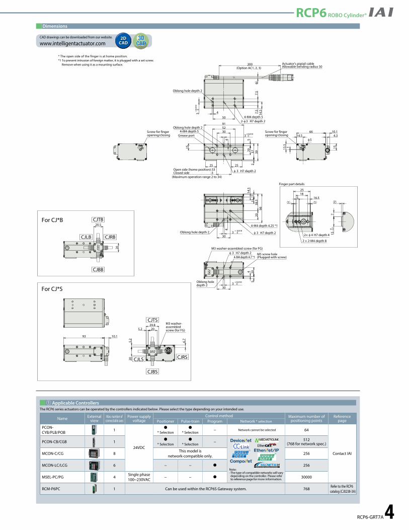
Dimensions
* The open side of the finger is at home position.*1 To prevent intrusion of foreign matter, it is plugged with a set screw.
Remove when using it as a mounting surface.
① Applicable ControllersThe RCP6 series actuators can be operated by the controllers indicated below. Please select the type depending on your intended use.
Name External view
Max. number of connectable axes
Power supply voltage
Control method Maximum number of positioning points
Reference pagePositioner Pulse-train Program Network * selection
PCON- CYB/PLB/POB
1
24VDC
�* Selection
�* Selection
− Network cannot be selected 64
Contact IAI
PCON-CB/CGB 1 �* Selection
�* Selection
−
Note: · The type of compatible networks will vary depending on the controller. Please refer to reference page for more information.
512(768 for network spec.)
MCON-C/CG 8This model is
network-compatible only.256
MCON-LC/LCG 6 − − � 256
MSEL-PC/PG 4Single phase 100~230VAC
− − � 30000
RCM-P6PC 1 Can be used within the RCP6S Gateway system. 768 Refer to the RCP6 catalog (CJ0238-3A)
5.2
5.2 20
20
6.7
29.8 M3 washer-assembled screw (for FG)
CJLS CJRS
CJBS
CJTS
93 10.1
For CJ*S
20.5
20
CJTB
CJRB
CJBB
CJLB
For CJ*B
30
20
φ 3 H7 depth 2
4-M4 depth 4.25 *1
3 +
0.0100
38.5
66
7
4
14.5
15
Oblong hole depth 2
20
3 +
0.0100
4
4-M4 depth 4.7 *1φ 3 H7 depth 2
30
5M3 washer-assembled screw (for FG)
M5 screw hole(Plugged with screw)
Oblong hole depth 2
91
3052
520
15
φ 3 H7 depth 2
3 + 0.0100
4
37
4-M4 depth 5
Open side (home position):33Closed side :3
(Maximum operation range 2 to 34)
239
2525
Oblong hole depth 2
Grease port
6
200(Option AC1, 2, 3)
50 4-M4 depth 543
+ 0.01
00
7.5
7.5
14.5
2-φ3 H7 depth 2
Oblong hole depth 2
Actuator's pigtail cableAllowable bending radius 50
Screw for finger opening/closing
10.14.314.5
13.5
66
151
φ5
Screw for finger opening/closing
15 16.5
25
1
2 × 2-M4 depth 8
2× φ 4 H7 depth 4
18
Finger part details
715
-0 0.1
2
CAD drawings can be downloaded from our website.
www.intelligentactuator.com2DCAD2DCAD
3DCAD3D
CAD
RCP6 ROBO Cylinder®

5 RCP6-GRT7B
RCP6 ROBO Cylinder®
RCP6-GRT7B Thin Slide Type
2-Finger Gripper
Grip
forc
e (N
)0
0 10 20Current limit value (Ratio %)* Grip force is the sum of both fingers
30 40 50 60 8070
4080
120160
150
200
320300
240280
Deceleration ratio +2Deceleration ratio: 2
Deceleration ratio +1Deceleration ratio: 1
28P: Stepper Motor 28£ Size
WA: Battery-less Absolute
N: NoneP: 1mS: 3m
M: 5mX ££: Specified Length
Please refer to the option price list below.
* Be sure to fill in one of the following options for the cable exit direction.
40:40mm80:80mm
1: Feed Screw Lead 2mm Pulley Deceleration Ratio 1.25
2: Feed Screw Lead 2mm Pulley Deceleration Ratio 2.5
¢ Model Specification Items
* Please note that, when gripping (pushing), the speed is fixed at 5 mm/s.
* The gripping force graph above shows numbers for reference. Please allow margins up to ±15%.
¢ Gripping Force vs. Electric Current LimitThe gripping (pushing) force can be adjusted freely within the range of electric current limits of 20% to 70%.
(1) The maximum opening/closing speed indicates the operating speed on one side. The relative operating speed is twice this value.
(2) The maximum gripping force is the sum of the gripping forces of both fingers, at a gripping point where there is no offset or overhang distance. The workpiece weight that can be actually moved depends on the friction coefficient between the gripper fingers and the workpiece, as well as on the shape of the workpiece. As a rough guide, a workpiece 's weight should not exceed 1/10 to 1/20 of the gripping force. (See page 9 for details.)
(3) The rated acceleration while moving is 0.3 G.
P3: PCON MCON MSEL
P5: RCM-P6PC* Does not include a controller.* Please refer to P.2 for more information about the model specification items.
Legend: ① Stroke ② Applicable Controllers ③ Cable Length ④ Options (Unit: mm/s)
Actuator Specifications¢ Stroke and Max Opening/Closing Speed
Deceleration ratio pattern
Max grip force (N)Model specification items Stroke
(mm)Stroke
Deceleration ratio40~80
(mm)
1
2
RCP6-GRT7B-WA-28P-1-① -② -③ -④
RCP6-GRT7B-WA-28P-2-① -② -③ -④
1
2
150 (one side 75)
300 (one side 150)
40 80(One side 20), (One side 40)
40 80(One side 20), (One side 40)
120
60
④Options
* Be sure to select a symbol for the cable exit direction.
Name Option code Reference pageActuator's pigtail cable 1m specification AC1 P. 8Actuator's pigtail cable 2m specification AC2 P. 8Actuator's pigtail cable 3m specification AC3 P. 8Rear cable exit from top C JTB P. 8Rear cable exit from left side C JLB P. 8Rear cable exit from right side C JRB P. 8Rear cable exit from bottom C JBB P. 8Side cable exit from top C JTS P. 8Side cable exit from left side C JLS P. 8Side cable exit from right side C JRS P. 8Side cable exit from bottom C JBS P. 8Non-motor end specification NM P. 8
Actuator Specifications
DescriptionItemTiming belt + left/right trapezoidal screw f10±0.01mmOne side 0.2mm or lessOne side 0.2mm or lessMa: 7.5N·m Mb: 7.5N·m Mc: 15.3N·m0.68kg (40 stroke), 0.84kg (80 stroke)0~40°C, 85% RH or less (non-condensing)
L2
L1
③ Cable Length
Specified length
Robot cable
Type Cable code
Standard typeP(1m)S(3m)M(5m)X06 (6m) ~ X10 (10m)X11 (11m) ~ X15 (15m)X16 (16m) ~ X20 (20m)*R01 (1m) ~ R03 (3m)R04 (4m) ~ R05 (5m)R06 (6m) ~ R10 (10m)R11 (11m) ~ R15 (15m)R16 (16m) ~ R20 (20m)*
Cable between actuator and controller.* When changing the Actuator's pigtail cable length as an option, make sure the total cable
length between the actuator and the controller is within 20m.
* For L1 and L2, please refer to the gripper selection method on P.9.* The gripping force in the graph below assumes that L1 and L2
the figure above are zero. (Refer to p.10 for the rough guide gripping force at each distance of L1.) Also note that the gripping force is the sum of the gripping forces of both fingers.
24 VStepper Motor
VerticalHorizontal
Ceiling
Side
P
O I N T
SelectionNotes
OptionsCable LengthApplicable Controllers
StrokeDeceleration Ratio Pattern
Motor TypeEncoder TypeTypeSeries
28PWAGRT7BRCP6
Drive systemPositioning repeatabilityBacklashLost motionAllowable static momentMassAmbient operating temperature/humidity
Body Width
66 mm
① Stroke
① Stroke(mm) RCP6- GRT7B
40 �
80 �
RCP6 ROBO Cylinder®
* Please check the Options reference pages to confirm each option.
RCP6-GRT7B 6
RCP6 ROBO Cylinder® RCP6 ROBO Cylinder®
5.2
5.2 20
20
29.8
6.7
M3 washer-assembled screw (for FG)
CJLS CJRS
CJBS
CJTS
125 10.1
For CJ*S
20.5
20
CJTB
CJRB
CJBB
CJLB
For CJ*B
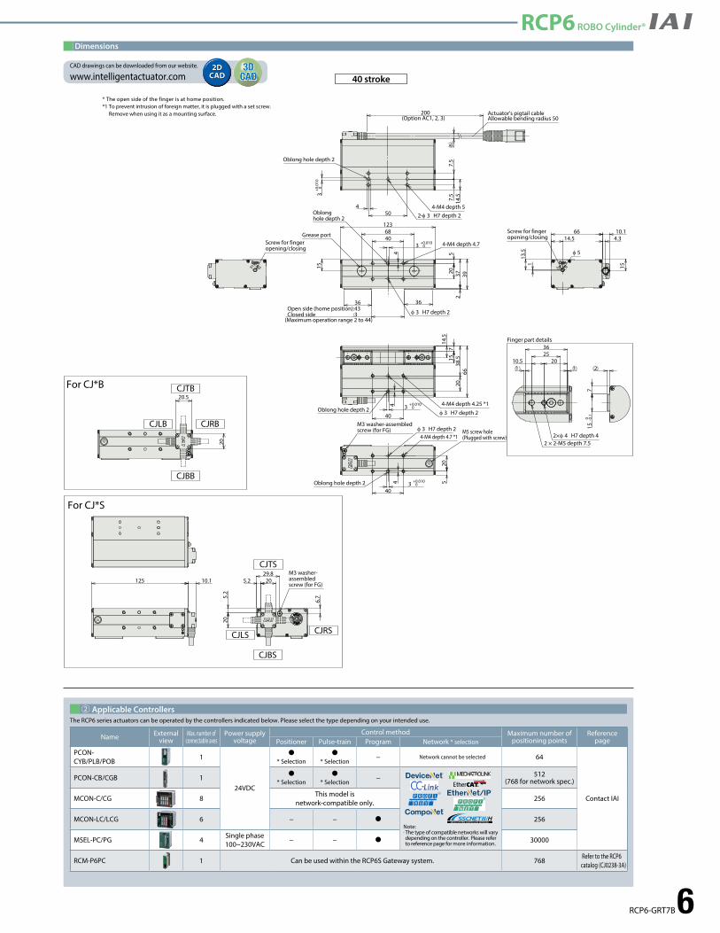
Dimensions
* The open side of the finger is at home position.*1 To prevent intrusion of foreign matter, it is plugged with a set screw.
Remove when using it as a mounting surface.
② Applicable ControllersThe RCP6 series actuators can be operated by the controllers indicated below. Please select the type depending on your intended use.
40 stroke
40
2038
.566
φ 3 H7 depth 23 +
0.01004 4-M4 depth 4.25 *1
714
.515
Oblong hole depth 2
4-M4 depth 4.7 *15
20
3 +
0.01004
φ 3 H7 depth 2
40
M5 screw hole(Plugged with screw)
Oblong hole depth 2
M3 washer-assembled screw (for FG)
4068
520
3 +
0.0100
4
φ 3 H7 depth 2
4-M4 depth 4.7
37
123
Open side (home position):43Closed side :3
(Maximum operation range 2 to 44)
2
15
39
3636
Grease port
Oblong hole depth 2
6
200(Option AC1, 2, 3)
50
7.5
7.5
4
3 + 0.
010
0
14.5
2-φ 3 H7 depth 24-M4 depth 5
Oblong hole depth 2
Actuator's pigtail cableAllowable bending radius 50
Screw for finger opening/closing
10.1
15
4.314.5
13.5
66
1
φ 5
Screw for finger opening/closing
1
36
12010.5
2×φ 4 H7 depth 42 × 2-M5 depth 7.5
25
Finger part details
715
-0 0.1
2
CAD drawings can be downloaded from our website.
www.intelligentactuator.com2DCAD2DCAD
3DCAD3D
CAD
Name External view
Max. number of connectable axes
Power supply voltage
Control method Maximum number of positioning points
Reference pagePositioner Pulse-train Program Network * selection
PCON- CYB/PLB/POB
1
24VDC
�* Selection
�* Selection
− Network cannot be selected 64
Contact IAI
PCON-CB/CGB 1 �* Selection
�* Selection
−
Note: · The type of compatible networks will vary depending on the controller. Please refer to reference page for more information.
512(768 for network spec.)
MCON-C/CG 8This model is
network-compatible only.256
MCON-LC/LCG 6 − − � 256
MSEL-PC/PG 4Single phase 100~230VAC
− − � 30000
RCM-P6PC 1 Can be used within the RCP6S Gateway system. 768 Refer to the RCP6 catalog (CJ0238-3A)
RCP6 ROBO Cylinder®
7 RCP6-GRT7B
RCP6 ROBO Cylinder®
5.2
5.2 20
20
29.8
6.7
M3 washer-assembled screw (for FG)
CJLS CJRS
CJBS
CJTS
D 10.1
For CJ*S
20.5
20
CJTB
CJRB
CJBB
CJLB
For CJ*B
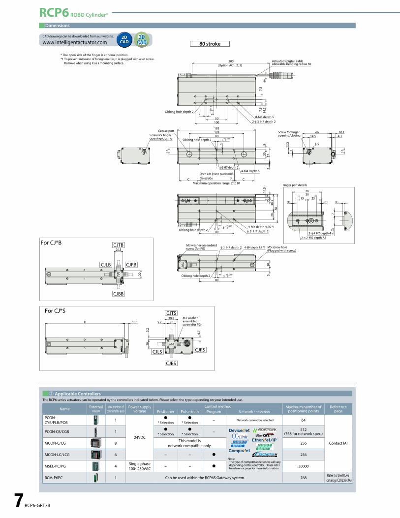
Dimensions
* The open side of the finger is at home position.*1 To prevent intrusion of foreign matter, it is plugged with a set screw.
Remove when using it as a mounting surface.
② Applicable ControllersThe RCP6 series actuators can be operated by the controllers indicated below. Please select the type depending on your intended use.
80 stroke
1
46
12315
2×φ4 H7 depth 42 × 2-M5 depth 7.5
30
Finger part details
715
-0 0.1
2
80
2038
.566
4-M4 depth 4.25 *1φ 3 H7 depth 2
3 +
0.0100
4
14.5
715
4-M4 depth 4.7 *1
520
3 +
0.0100
4
φ 3 H7 depth 2
80
M3 washer-assembled screw (for FG) M5 screw hole
(Plugged with screw)
80128
520
3 +
0.0100
4
37
183
2
Open side (home position):83Closed side :3
Maximum operation range: 2 to 84
15
CC
Grease port
6
200(Option AC1, 2, 3)
50
7.5
7.5
2-φ 3 H7 depth 2
4 3 + 0.
010
0
100
8-M4 depth 5
14.5
Oblong hole depth 2
Actuator's pigtail cableAllowable bending radius 50
Screw for finger opening/closing
10.1
15
4.314.5
13.5
66
1
φ 5
Screw for finger opening/closing
φ3 H7 depth 24-M4 depth 5
Oblong hole depth 2
Oblong hole depth 2
Oblong hole depth 2
Name External view
Max. number of connectable axes
Power supply voltage
Control method Maximum number of positioning points
Reference pagePositioner Pulse-train Program Network * selection
PCON- CYB/PLB/POB
1
24VDC
�* Selection
�* Selection
− Network cannot be selected 64
Contact IAI
PCON-CB/CGB 1 �* Selection
�* Selection
−
Note: · The type of compatible networks will vary depending on the controller. Please refer to reference page for more information.
512(768 for network spec.)
MCON-C/CG 8This model is
network-compatible only.256
MCON-LC/LCG 6 − − � 256
MSEL-PC/PG 4Single phase 100~230VAC
− − � 30000
RCM-P6PC 1 Can be used within the RCP6S Gateway system. 768 Refer to the RCP6 catalog (CJ0238-3A)
CAD drawings can be downloaded from our website.
www.intelligentactuator.com2DCAD2DCAD
3DCAD3D
CAD
RCP6 ROBO Cylinder®
Options 8
RCP6 ROBO Cylinder® Options
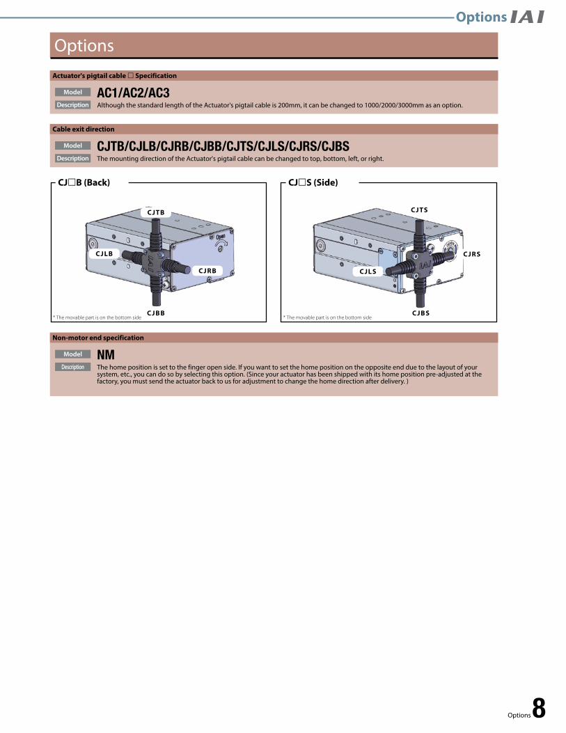
Cable exit direction
Description
Model
The mounting direction of the Actuator's pigtail cable can be changed to top, bottom, left, or right.CJTB/CJLB/CJRB/CJBB/CJTS/CJLS/CJRS/CJBS
Actuator's pigtail cable £ Specification
Description
Model
Although the standard length of the Actuator's pigtail cable is 200mm, it can be changed to 1000/2000/3000mm as an option.AC1/AC2/AC3
Options
Non-motor end specification
The home position is set to the finger open side. If you want to set the home position on the opposite end due to the layout of your system, etc., you can do so by selecting this option. (Since your actuator has been shipped with its home position pre-adjusted at the factory, you must send the actuator back to us for adjustment to change the home direction after delivery. )
Description
Model NM
CJ£B (Back)
C JBB
CJ£S (Side)
C JTS
C JBS* The movable part is on the bottom side * The movable part is on the bottom side
CJTB
C JLB
C JRB C JLS
C JRS
Options

9 Reference Data
Reference Data
Mb
F
L2
L1
Load point
Check the required grip force and allowable workpiece mass
Step 1
Check external force applied to fingers
Step 3
Check the gripping point distance
Step 2
Check the required grip force and allowable workpiece massStep 1
Check the gripping point distanceStep 2
When gripping the workpiece with frictional grip force, calculate the required grip force as follows.
F: Grip force (N) ... Total value of push force of each clawμ: Static friction coefficient between the finger
attachment and the workpiecem: Workpiece mass (kg)g: Gravitational acceleration (=9.8m/s2)
The conditions under which the work part remains statically gripped without dropping are as follows:
Fμ > Wmg
μF >
mgμ
F > ×2 (safety factor)
mg0.1~0.2
F > ×2 = (10~20) × mg
When the friction coefficient is μ0.1 ~ 0.2
(1) For normal transfer
(2) When considerable acceleration, deceleration, or impact force is applied when transferring the workpiece
In addition to gravity, if a stronger inertial force operates on the workpiece then select a model with an even higher safety factor.
For ordinary workpiece transferring
Required grip force: 10~20 times or more the workpiece massMax. allowable mass: Not more than 1/10th to 1/20th the gripping force
Even if the gripping point distance is within the limit range, keep it as small and lightweight as possible.If the fingers are long and large, or if the mass is large, inertial force and bending moment during opening and closing may worsen the performance and adversely affect the guide section.
Assuming a recommended safety factor of 2 for normal transfer, the required gripping force is calculated as follows:
When large acceleration, deceleration, or shock is applied
Required grip force: 30~50 times or more the workpiece massMax. allowable mass: 1/30~1/50 or less of the grip force
Use the actuator so that the distances (L1, L2) from the finger mounting surface to the gripping point fall in the ranges specified below. If the limits are exceeded, excessive moments may act upon the sliding part of the finger and internal mechanism, negatively affecting the service life of the actuator.
Slide type
(2) Allowable load moment
Calculate Ma and Mc with L1, and Mb with L2. Make sure the moment applied to each finger is less than the maximum allowable load moment.
(1) Allowable vertical load
Make sure that the vertical load applied to each finger is less than the allowable load.
Check external force applied to fingersStep 3
The allowable external force when applying moment load to each claw is
M (Maximum allowable moment (N·m) L(mm)×10-3Allowable load F(N) >
Calculate both L1 and L2 for the allowable load F (N).
Check that the external force applied to the finger is less than the calculated allowable load F (N) (the smaller value of L1 and L2).
* The load point above indicates the load position on the fingers. The position varies depending on the type of load. · Load due to grip force: Gripping point · Load due to gravity: Center mass location · Inertial force during travel, centrifugal force during swivel: Center mass location
The load moment is the total value calculated for each type of load.
Ma3.67.5
598898
RCP6-GRT7ARCP6-GRT7B
ModelMaximum allowable load moment
(N·m) (Note 2)Allowable vertical load F (N)(Note 1)
Mb3.67.5
Mc10.215.3
(Note 1) The allowable value above indicates a static value. (Note 2) Indicates the allowable value per finger.
* The weight of the finger and the workpiece weight are also part of the external force.Other external forces applied to the fingers are the centrifugal force when swiveling the gripper with the workpiece gripped and the inertia force due to acceleration/deceleration during travel.
RCP6-GRT7A
RCP6-GRT7B (Deceleration ratio: 1) RCP6-GRT7B (Deceleration ratio: 2)
Ove
rhan
g a
mo
un
t L2
[mm
]
Gripping current 30%
Gripping current 50%
Gripping current 70%
Gripping point L1 [mm]
Ove
rhan
g a
mo
un
t L2
[mm
]
Gripping current 30%
Gripping current 50%
Gripping current 70%
Gripping point L1 [mm]
Ove
rhan
g a
mo
un
t L2
[mm
]
Gripping current 30%
Gripping current 50%
Gripping current 70%
Gripping point L1 [mm]
Deceleration ratio 2Deceleration ratio 1
MaMc
Guideline for load shape and mass1. These graphs show the grip force based on the gripping point distance when the maximum grip force is taken as 100%.2. The gripping point distance indicates the vertical distance from the �nger attachment mounting surface to
the gripping point.3. Grip force may vary due to individual di�erences. Consider this as a guideline only.
Mb
F
L2
L1
Load point
Check the required grip force and allowable workpiece mass
Step 1
Check external force applied to fingers
Step 3
Check the gripping point distance
Step 2
Check the required grip force and allowable workpiece massStep 1
Check the gripping point distanceStep 2
When gripping the workpiece with frictional grip force, calculate the required grip force as follows.
F: Grip force (N) ... Total value of push force of each clawμ: Static friction coefficient between the finger
attachment and the workpiecem: Workpiece mass (kg)g: Gravitational acceleration (=9.8m/s2)
The conditions under which the work part remains statically gripped without dropping are as follows:
Fμ > Wmg
μF >
mgμ
F > ×2 (safety factor)
mg0.1~0.2
F > ×2 = (10~20) × mg
When the friction coefficient is μ0.1 ~ 0.2
(1) For normal transfer
(2) When considerable acceleration, deceleration, or impact force is applied when transferring the workpiece
In addition to gravity, if a stronger inertial force operates on the workpiece then select a model with an even higher safety factor.
For ordinary workpiece transferring
Required grip force: 10~20 times or more the workpiece massMax. allowable mass: Not more than 1/10th to 1/20th the gripping force
Even if the gripping point distance is within the limit range, keep it as small and lightweight as possible.If the fingers are long and large, or if the mass is large, inertial force and bending moment during opening and closing may worsen the performance and adversely affect the guide section.
Assuming a recommended safety factor of 2 for normal transfer, the required gripping force is calculated as follows:
When large acceleration, deceleration, or shock is applied
Required grip force: 30~50 times or more the workpiece massMax. allowable mass: 1/30~1/50 or less of the grip force
Use the actuator so that the distances (L1, L2) from the finger mounting surface to the gripping point fall in the ranges specified below. If the limits are exceeded, excessive moments may act upon the sliding part of the finger and internal mechanism, negatively affecting the service life of the actuator.
Slide type
(2) Allowable load moment
Calculate Ma and Mc with L1, and Mb with L2. Make sure the moment applied to each finger is less than the maximum allowable load moment.
(1) Allowable vertical load
Make sure that the vertical load applied to each finger is less than the allowable load.
Check external force applied to fingersStep 3
The allowable external force when applying moment load to each claw is
M (Maximum allowable moment (N·m) L(mm)×10-3Allowable load F(N) >
Calculate both L1 and L2 for the allowable load F (N).
Check that the external force applied to the finger is less than the calculated allowable load F (N) (the smaller value of L1 and L2).
* The load point above indicates the load position on the fingers. The position varies depending on the type of load. · Load due to grip force: Gripping point · Load due to gravity: Center mass location · Inertial force during travel, centrifugal force during swivel: Center mass location
The load moment is the total value calculated for each type of load.
Ma3.67.5
598898
RCP6-GRT7ARCP6-GRT7B
ModelMaximum allowable load moment
(N·m) (Note 2)Allowable vertical load F (N)(Note 1)
Mb3.67.5
Mc10.215.3
(Note 1) The allowable value above indicates a static value. (Note 2) Indicates the allowable value per finger.
* The weight of the finger and the workpiece weight are also part of the external force.Other external forces applied to the fingers are the centrifugal force when swiveling the gripper with the workpiece gripped and the inertia force due to acceleration/deceleration during travel.
RCP6-GRT7A
RCP6-GRT7B (Deceleration ratio: 1) RCP6-GRT7B (Deceleration ratio: 2)
Ove
rhan
g a
mo
un
t L2
[mm
]
Gripping current 30%
Gripping current 50%
Gripping current 70%
Gripping point L1 [mm]
Ove
rhan
g a
mo
un
t L2
[mm
]
Gripping current 30%
Gripping current 50%
Gripping current 70%
Gripping point L1 [mm]
Ove
rhan
g a
mo
un
t L2
[mm
]
Gripping current 30%
Gripping current 50%
Gripping current 70%
Gripping point L1 [mm]
Deceleration ratio 2Deceleration ratio 1
MaMc
Gripper Selection Method
* The greater the coefficient of static friction, the greater than maximum allowable work part mass be- comes. To ensure safety, however, select a model that can generate a gripping force of at least 10 to 20 times this work part mass.
Friction coefficient μ
W[mg]
F/2F/2
L2
L1
Slide top surface - Guide action point distance
Reference Data

Reference Data 10
Reference Data
Mb
F
L2
L1
Load point
Check the required grip force and allowable workpiece mass
Step 1
Check external force applied to fingers
Step 3
Check the gripping point distance
Step 2
Check the required grip force and allowable workpiece massStep 1
Check the gripping point distanceStep 2
When gripping the workpiece with frictional grip force, calculate the required grip force as follows.
F: Grip force (N) ... Total value of push force of each clawμ: Static friction coefficient between the finger
attachment and the workpiecem: Workpiece mass (kg)g: Gravitational acceleration (=9.8m/s2)
The conditions under which the work part remains statically gripped without dropping are as follows:
Fμ > Wmg
μF >
mgμ
F > ×2 (safety factor)
mg0.1~0.2
F > ×2 = (10~20) × mg
When the friction coefficient is μ0.1 ~ 0.2
(1) For normal transfer
(2) When considerable acceleration, deceleration, or impact force is applied when transferring the workpiece
In addition to gravity, if a stronger inertial force operates on the workpiece then select a model with an even higher safety factor.
For ordinary workpiece transferring
Required grip force: 10~20 times or more the workpiece massMax. allowable mass: Not more than 1/10th to 1/20th the gripping force
Even if the gripping point distance is within the limit range, keep it as small and lightweight as possible.If the fingers are long and large, or if the mass is large, inertial force and bending moment during opening and closing may worsen the performance and adversely affect the guide section.
Assuming a recommended safety factor of 2 for normal transfer, the required gripping force is calculated as follows:
When large acceleration, deceleration, or shock is applied
Required grip force: 30~50 times or more the workpiece massMax. allowable mass: 1/30~1/50 or less of the grip force
Use the actuator so that the distances (L1, L2) from the finger mounting surface to the gripping point fall in the ranges specified below. If the limits are exceeded, excessive moments may act upon the sliding part of the finger and internal mechanism, negatively affecting the service life of the actuator.
Slide type
(2) Allowable load moment
Calculate Ma and Mc with L1, and Mb with L2. Make sure the moment applied to each finger is less than the maximum allowable load moment.
(1) Allowable vertical load
Make sure that the vertical load applied to each finger is less than the allowable load.
Check external force applied to fingersStep 3
The allowable external force when applying moment load to each claw is
M (Maximum allowable moment (N·m) L(mm)×10-3Allowable load F(N) >
Calculate both L1 and L2 for the allowable load F (N).
Check that the external force applied to the finger is less than the calculated allowable load F (N) (the smaller value of L1 and L2).
* The load point above indicates the load position on the fingers. The position varies depending on the type of load. · Load due to grip force: Gripping point · Load due to gravity: Center mass location · Inertial force during travel, centrifugal force during swivel: Center mass location
The load moment is the total value calculated for each type of load.
Ma3.67.5
598898
RCP6-GRT7ARCP6-GRT7B
ModelMaximum allowable load moment
(N·m) (Note 2)Allowable vertical load F (N)(Note 1)
Mb3.67.5
Mc10.215.3
(Note 1) The allowable value above indicates a static value. (Note 2) Indicates the allowable value per finger.
* The weight of the finger and the workpiece weight are also part of the external force.Other external forces applied to the fingers are the centrifugal force when swiveling the gripper with the workpiece gripped and the inertia force due to acceleration/deceleration during travel.
RCP6-GRT7A
RCP6-GRT7B (Deceleration ratio: 1) RCP6-GRT7B (Deceleration ratio: 2)
Ove
rhan
g a
mo
un
t L2
[mm
]
Gripping current 30%
Gripping current 50%
Gripping current 70%
Gripping point L1 [mm]
Ove
rhan
g a
mo
un
t L2
[mm
]
Gripping current 30%
Gripping current 50%
Gripping current 70%
Gripping point L1 [mm]
Ove
rhan
g a
mo
un
t L2
[mm
]
Gripping current 30%
Gripping current 50%
Gripping current 70%
Gripping point L1 [mm]
Deceleration ratio 2Deceleration ratio 1
MaMc
Guideline for load shape and mass1. These graphs show the grip force based on the gripping point distance when the maximum grip force is taken as 100%.2. The gripping point distance indicates the vertical distance from the �nger attachment mounting surface to
the gripping point.3. Grip force may vary due to individual di�erences. Consider this as a guideline only.
RCP6-GRT7A RCP6-GRT7B (Deceleration ratio 1) RCP6-GRT7B (Deceleration ratio 2)
60
50
40
20
30
10
0
Gripping point distance (mm)
Gri
p fo
rce
(%)
0 20 40 60 160120 14010080
110
100
80
90
70
Change in grip force due to gripping point distance
60
50
40
20
30
10
0
Gripping point distance (mm)
Gri
p fo
rce
(%)
0 20 40 60 150120 1401008010 30 50 110 1309070
110
100
80
90
70
Change in grip force due to gripping point distance
60
50
40
20
30
10
0
Gripping point distance (mm)
Gri
p fo
rce
(%)
0 2010 30 40 1159080 100 110706050
110
100
80
90
70
Change in grip force due to gripping point distance
Gripper Selection Method
Mb
F
L2
L1
Load point
Check the required grip force and allowable workpiece mass
Step 1
Check external force applied to fingers
Step 3
Check the gripping point distance
Step 2
Check the required grip force and allowable workpiece massStep 1
Check the gripping point distanceStep 2
When gripping the workpiece with frictional grip force, calculate the required grip force as follows.
F: Grip force (N) ... Total value of push force of each clawμ: Static friction coefficient between the finger
attachment and the workpiecem: Workpiece mass (kg)g: Gravitational acceleration (=9.8m/s2)
The conditions under which the work part remains statically gripped without dropping are as follows:
Fμ > Wmg
μF >
mgμ
F > ×2 (safety factor)
mg0.1~0.2
F > ×2 = (10~20) × mg
When the friction coefficient is μ0.1 ~ 0.2
(1) For normal transfer
(2) When considerable acceleration, deceleration, or impact force is applied when transferring the workpiece
In addition to gravity, if a stronger inertial force operates on the workpiece then select a model with an even higher safety factor.
For ordinary workpiece transferring
Required grip force: 10~20 times or more the workpiece massMax. allowable mass: Not more than 1/10th to 1/20th the gripping force
Even if the gripping point distance is within the limit range, keep it as small and lightweight as possible.If the fingers are long and large, or if the mass is large, inertial force and bending moment during opening and closing may worsen the performance and adversely affect the guide section.
Assuming a recommended safety factor of 2 for normal transfer, the required gripping force is calculated as follows:
When large acceleration, deceleration, or shock is applied
Required grip force: 30~50 times or more the workpiece massMax. allowable mass: 1/30~1/50 or less of the grip force
Use the actuator so that the distances (L1, L2) from the finger mounting surface to the gripping point fall in the ranges specified below. If the limits are exceeded, excessive moments may act upon the sliding part of the finger and internal mechanism, negatively affecting the service life of the actuator.
Slide type
(2) Allowable load moment
Calculate Ma and Mc with L1, and Mb with L2. Make sure the moment applied to each finger is less than the maximum allowable load moment.
(1) Allowable vertical load
Make sure that the vertical load applied to each finger is less than the allowable load.
Check external force applied to fingersStep 3
The allowable external force when applying moment load to each claw is
M (Maximum allowable moment (N·m) L(mm)×10-3Allowable load F(N) >
Calculate both L1 and L2 for the allowable load F (N).
Check that the external force applied to the finger is less than the calculated allowable load F (N) (the smaller value of L1 and L2).
* The load point above indicates the load position on the fingers. The position varies depending on the type of load. · Load due to grip force: Gripping point · Load due to gravity: Center mass location · Inertial force during travel, centrifugal force during swivel: Center mass location
The load moment is the total value calculated for each type of load.
Ma3.67.5
598898
RCP6-GRT7ARCP6-GRT7B
ModelMaximum allowable load moment
(N·m) (Note 2)Allowable vertical load F (N)(Note 1)
Mb3.67.5
Mc10.215.3
(Note 1) The allowable value above indicates a static value. (Note 2) Indicates the allowable value per finger.
* The weight of the finger and the workpiece weight are also part of the external force.Other external forces applied to the fingers are the centrifugal force when swiveling the gripper with the workpiece gripped and the inertia force due to acceleration/deceleration during travel.
RCP6-GRT7A
RCP6-GRT7B (Deceleration ratio: 1) RCP6-GRT7B (Deceleration ratio: 2)
Ove
rhan
g a
mo
un
t L2
[mm
]
Gripping current 30%
Gripping current 50%
Gripping current 70%
Gripping point L1 [mm]
Ove
rhan
g a
mo
un
t L2
[mm
]
Gripping current 30%
Gripping current 50%
Gripping current 70%
Gripping point L1 [mm]
Ove
rhan
g a
mo
un
t L2
[mm
]
Gripping current 30%
Gripping current 50%
Gripping current 70%
Gripping point L1 [mm]
Deceleration ratio 2Deceleration ratio 1
MaMc
Reference Data

Catalog No. CE0252-1A (0817)
2690 W. 237th Street, Torrance, CA 90505 (800) 736-1712 110 E. State Pkwy, Schaumburg, IL 60173 (800) 944-0333
1220 Kennestone Circle, Suite 108, Marietta, GA 30066 (888) 354-9470
www.intelligentactuator.com
IAI Industrieroboter GmbHOber der Röth 4, D-65824 Schwalbach am Taunus, Germany
IAI (Shanghai) Co., Ltd.Shanghai Jiahua Business Center A8-303, 808,Hongqiao Rd., Shanghai 200030, China
IAI Robot (Thailand) Co., Ltd.825 Phairojkijja Tower 7th Floor, Debaratana Rd.,Bangna Nuea, Bangna, Bangkok 10260, Thailand
The information contained in this product brochure may change without prior notice due to product improvements.
Atlanta O�ce:Chicago O�ce:Headquarters:
IAI America, Inc.