thinking about field day antennas...thinking about field day antennas by jim wright n2gxj think...
TRANSCRIPT
Thinking about Field Day antennas By Jim Wright N2GXJ Think about it. The antenna system that you use for contesting is not likely to be your best choice for field day. Field day differs, fundamentally, from any other contesting or DX activity where your score is influenced by the number of states/provinces/DXCC entities you can achieve for multipliers. For field day, you get no extra credit for contacting that far away station. It's just total number of contacts that are measured. The best antenna for field day is going to be the one that gets your signal to where the most number of field day stations are. And for us here on the East Coast, that's NOT where the DX is!
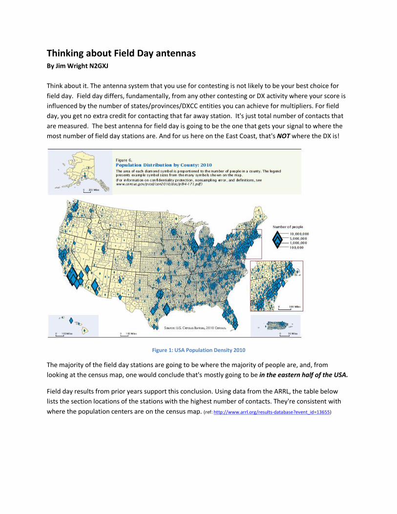
Figure 1: USA Population Density 2010
The majority of the field day stations are going to be where the majority of people are, and, from looking at the census map, one would conclude that's mostly going to be in the eastern half of the USA.
Field day results from prior years support this conclusion. Using data from the ARRL, the table below lists the section locations of the stations with the highest number of contacts. They're consistent with where the population centers are on the census map. (ref: http://www.arrl.org/results-database?event_id=13655)

Thinking about Field Day antennas
2
Table 1: Section locations of top scoring field day stations (2011)
Designation Section locators of top scoring 2011 field day stations
8A NC, SNJ, VA, OH, GA, IL, OH
7A NFL, MDC, WMA, KY, OH, ORG, EPA
6A VA, SNJ, WWA, IL, OH, NFL, IN, WMA
Taking the major population cluster information and putting it on an azimuth map of the USA centered on our SNJ location, a directional pattern emerges. To get to where the majority of field day sites are going to be, an ideal antenna system for us in SNJ is going to be one that can close-in blanket cover a 200 mile stretch up and down the East coast, plus have some short-skip directivity towards the West-Southwest into the target zone drawn on the map below. (ref: http://ns6t.net/azimuth/azimuth.html).
Figure 2: Target coverage zone, from our SNJ location
Any antenna candidates come to mind?

Thinking about Field Day antennas
3
Site Location We have to keep in mind that this is field day where we operate "off the grid" using portable antennas setup in a field near a 4H fairground. So some preference must be given to easy set up in an open field, or with the help from one of the few trees that can be found on the periphery of the setup location. An aerial view of our field day site is shown in the following picture (North is up, ref: www.bing.com/maps).
Figure 3: W2MMD Field Day Site
As you can see in the picture, at our field day site there are some taller pine trees along the South-Southeastern side of the field, and some shorter scrubbier trees available to the north-northeast, on the other side of the dirt driveway (North is up in the picture). Most of the available space is open field, with some car parking spaces in front of the on-site trailer that we use as a club-house for socializing (and for preparing field day dinner). The tall tree line at the bottom of the picture conveniently lines up parallel to the West-Southwest direction needed to reach the majority of the target zone outlined in Figure 2. By rule we’re allowed to set up all stations within a 1,000 foot radius, but as you can see, the area we setup in is smaller than that.
Propagation As many will recall from their license studies, due to the nature of the ionosphere and radio propagation at different frequencies, we're just not going to be able to get coverage into the whole of our target
Thinking about Field Day antennas
4
coverage zone on all the amateur bands that we intend to operate on during field day. So just what coverage can we expect throughout the day on each band?
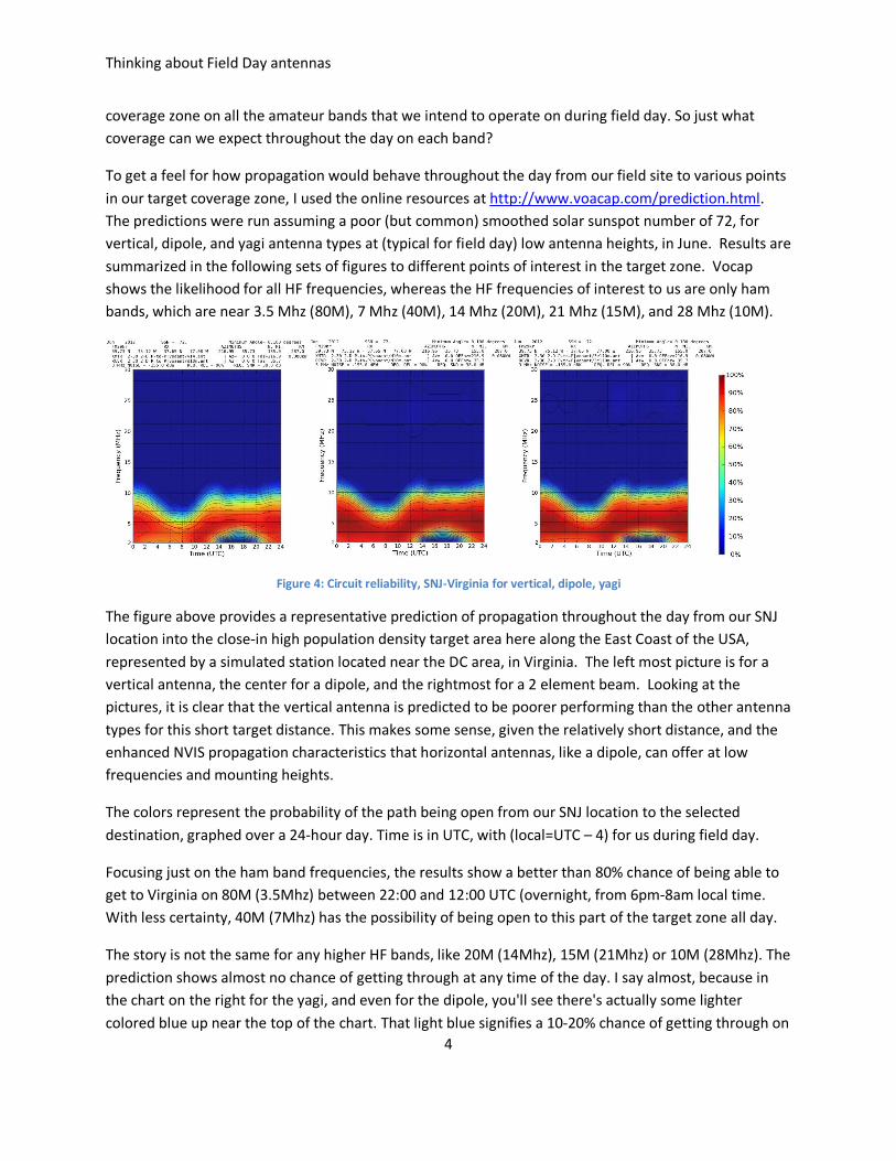
To get a feel for how propagation would behave throughout the day from our field site to various points in our target coverage zone, I used the online resources at http://www.voacap.com/prediction.html. The predictions were run assuming a poor (but common) smoothed solar sunspot number of 72, for vertical, dipole, and yagi antenna types at (typical for field day) low antenna heights, in June. Results are summarized in the following sets of figures to different points of interest in the target zone. Vocap shows the likelihood for all HF frequencies, whereas the HF frequencies of interest to us are only ham bands, which are near 3.5 Mhz (80M), 7 Mhz (40M), 14 Mhz (20M), 21 Mhz (15M), and 28 Mhz (10M).
Figure 4: Circuit reliability, SNJ-Virginia for vertical, dipole, yagi
The figure above provides a representative prediction of propagation throughout the day from our SNJ location into the close-in high population density target area here along the East Coast of the USA, represented by a simulated station located near the DC area, in Virginia. The left most picture is for a vertical antenna, the center for a dipole, and the rightmost for a 2 element beam. Looking at the pictures, it is clear that the vertical antenna is predicted to be poorer performing than the other antenna types for this short target distance. This makes some sense, given the relatively short distance, and the enhanced NVIS propagation characteristics that horizontal antennas, like a dipole, can offer at low frequencies and mounting heights.
The colors represent the probability of the path being open from our SNJ location to the selected destination, graphed over a 24-hour day. Time is in UTC, with (local=UTC – 4) for us during field day.
Focusing just on the ham band frequencies, the results show a better than 80% chance of being able to get to Virginia on 80M (3.5Mhz) between 22:00 and 12:00 UTC (overnight, from 6pm-8am local time. With less certainty, 40M (7Mhz) has the possibility of being open to this part of the target zone all day.
The story is not the same for any higher HF bands, like 20M (14Mhz), 15M (21Mhz) or 10M (28Mhz). The prediction shows almost no chance of getting through at any time of the day. I say almost, because in the chart on the right for the yagi, and even for the dipole, you'll see there's actually some lighter colored blue up near the top of the chart. That light blue signifies a 10-20% chance of getting through on
Thinking about Field Day antennas
5
the higher frequencies during the daylight hours (starting around 12:00 UTC, 8am local), even with poor sunspot numbers.
Unfortunately for us, the 20M band (14Mhz), which is one of the most popular ham bands, is not predicted to have reliable communications into this high-density portion of our target zone at any time during the day. It seems like it is too far for ground wave, and too close for short-skip at this frequency, that is unless we get better solar conditions!
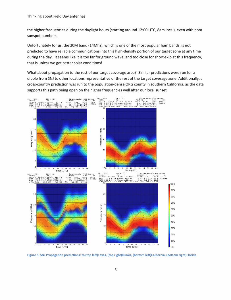
What about propagation to the rest of our target coverage area? Similar predictions were run for a dipole from SNJ to other locations representative of the rest of the target coverage zone. Additionally, a cross-country prediction was run to the population-dense ORG county in southern California, as the data supports this path being open on the higher frequencies well after our local sunset.
Figure 5: SNJ Propagation predictions: to (top left)Texas, (top right)Illinois, (bottom left)California, (bottom right)Florida
Thinking about Field Day antennas
6
Unlike Figure 4, in Figure 5 the 20M band (14Mhz) is shown to be a work-horse band to many other population centers in our target coverage area throughout the day. 15M (21Mhz) has a reasonable chance of openings towards Texas and California, from about 10am to almost midnight (local).
So now, with an understanding of the desired target coverage zone, and with expectations for where each amateur band will have best coverage into the target area, it's time to think about antennas to deliver the desired coverage for the bands of interest. Bring on the candidates!
The Candidates After an enjoyable review of wire antennas in various handbooks, and some experimenting with the excellent 4NEC2 antenna modeling software (http://home.ict.nl/~arivoors), I've narrowed the multitude of choices down to a few candidates. Based on your experiences and interests, you might come up with a different list, but for me, I ended up with a number of candidates, including:
• a directed sloping dipole
• an inverted V beam
• a pair of phased verticals
• a horizontal wire beam
• vertical delta and rectangular loops
• horizontal multi-wavelength loop
I'll summarize each, before ending up with a candidate solution. Maybe there's one that might catch your interest to modify or apply to operation on your assigned band too?
Directed sloping dipole As shown in the 4nec2 results below, sloping a horizontal dipole can skew the normal pattern of a low-mounted dipole to favor the direction of the slope.

Thinking about Field Day antennas
7
As shown in the horizontal (red colored) gain plot, the sloping dipole has a very wide beamwidth, with only a minor reduction in gain towards the 'uphill' end of the sloping wire. There's little forward gain, but the pattern is horizontally wide enough to cover our entire target area from Illinois on down to Florida, with decent energy directed for short-skip to the sides and towards the direction of the slope.
To increase the forward gain slightly, a second slightly longer reflector wire can be mounted behind the driven sloping dipole. The 4nec2 output shows the improved pattern results.
Forward gain has increased without sacrificing much in the beamwidth. The directed sloping dipole looks like a good field day antenna candidate for my SNJ location, as long as a tall tree or mast can be found to allow me to orient the down-slope side of the antenna towards the west-southwest.

Thinking about Field Day antennas
8
Inverted V Beam The inverted V has the field day advantage of only needing one tall center support. The radiation pattern of an inverted V is slightly bi-directional, with much of the energy going in the up direction (suitable for close-in NVIS at low frequencies), as shown in the 4nec2 output below. This may be a good candidate for operating on 80M or 40M to gain coverage to all those close-in stations in the prime portion of our target zone, but my assignment is 15M. On 15M that upward energy is going to be wasted energy, as that band is too high in frequency at that angle to be reflected back by the ionosphere.
If a second inverted V is added as a reflector, the pattern can be adjusted to become lower angle and more directional. Gain along the main axis is increased with a corresponding decrease in vertical and rear skywave propagation. Mechanically, this can be accomplished by stringing additional inverted V's along a clothesline strung across to another vertical support, or sloped down from the tall support to a point some distance from the main support. Though the additional V's on the clothesline can either be configured as directors or reflectors, I'm choosing to consider a V director on the lower side of the support wire, with results as shown in the following 4nec2 example.

Thinking about Field Day antennas
9
Creating this inverted V-beam offers does offer some improvements over the standard inverted V, while still maintaining a nice broad beamwidth for coverage into the Illinois down to Florida target area. With a fairly high take-off angle, for the lower bands, there is the potential for good close-in skip coverage, which is good for our SNJ location. Variants on this design may be worth further consideration.
Phased Verticals A vertical antenna has the advantage of being relatively easy to put up in an open field for field day. To add some directivity, and put more signal into our target coverage area, a second vertical can be added and fed out of phase to produce a higher gain directional pattern similar to the one we're looking for. An example of running with a pair of phased verticals is shown in the 4nec2 results below.
The pattern is broad to direct the signal across all of our target zone. Though the peak gain is at a lower take off angle (65 dg) than for the inverted V beam, the energy at that angle (2.47 dB) is no better than the 2.7 dB predicted at that angle for the V beam. The main difference between these candidates then becomes the ease of assembly, and the orientation of the polarization. I don’t have any statistics to say which polarization is better, but it would seem to me that you would do best to match the polarization of the majority of close-in ground-wave reachable stations you intend to contact. If they’re using dipoles, you might do better with a dipole as well.
Still, the field assembly advantages of a vertical for use in an open field are hard to ignore. If going vertical, a phased pair may be worth considering.
Horizontal Wire Beam Though mechanically more complex, it is possible to assemble a small wire beam using horizontal supports mounted on top of a single vertical mast. Wire beam options in this category can include Moxon, X-beam, M-beam, Hex-beam, and other similar designs and variants. I found an article online that compared some of these options, and have decided to look at the broadband Hex beam as a serious contender. The Hex beam is a symmetric antenna suitable for mounting on top of a single mast/pole.
Thinking about Field Day antennas
10
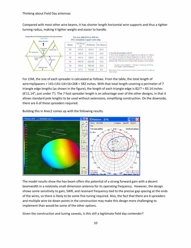
Compared with most other wire beams, it has shorter length horizontal wire supports and thus a tighter turning radius, making it lighter weight and easier to handle.
For 15M, the size of each spreader is calculated as follows. From the table, the total length of wire+tipSpacers = 141+141+16+16+268 = 582 inches. With that total length covering a perimeter of 7 triangle edge lengths (as shown in the figure), the length of each triangle edge is 82/7 = 83.14 inches (6'11.14"; just under 7'). The 7 foot spreader length is an advantage over of the other designs, in that it allows standard pole lengths to be used without extensions, simplifying construction. On the downside, there are 6 of these spreaders required.
Building this in 4nec2 comes up with the following results.
The model results show the hex beam offers the potential of a strong forward gain with a decent beamwidth in a relatively small dimension antenna for its operating frequency. However, the design shows some sensitivity to gain, SWR, and resonant frequency tied to the precise gap spacing at the ends of the wires, so there is likely to be some fine tuning required. Also, the fact that there are 6 spreaders and multiple wire tie-down points in the construction may make this design more challenging to implement than would be some of the other options.
Given the construction and tuning caveats, is this still a legitimate field day contender?
Thinking about Field Day antennas
11
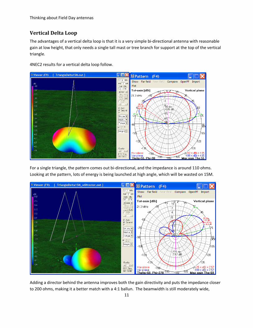
Vertical Delta Loop The advantages of a vertical delta loop is that it is a very simple bi-directional antenna with reasonable gain at low height, that only needs a single tall mast or tree branch for support at the top of the vertical triangle.
4NEC2 results for a vertical delta loop follow.
For a single triangle, the pattern comes out bi-directional, and the impedance is around 110 ohms. Looking at the pattern, lots of energy is being launched at high angle, which will be wasted on 15M.
Adding a director behind the antenna improves both the gain directivity and puts the impedance closer to 200 ohms, making it a better match with a 4:1 ballun. The beamwidth is still moderately wide,

Thinking about Field Day antennas
12
though the ability to rotate it slightly may be advantageous to differentiate between Texas and upper midwestern target areas.
Vertical Rectangle Changing the triangle shape to a vertical rectangle brings the feedpoint impedance down to 50 ohms, making a match easy. The pattern looks similar to that of the vertical triangle, in that it is also bi-directional, but with slightly more gain.
As with the delta loop, a reflector or director can be added to this design to give it better directivity into our target coverage area.
This is mechanically a bit more complicated of a design, as some form of horizontal support at the top of the mast would be needed to hold the rectangle in shape. Adding a director or reflector would require some form of support arm, similar to what is used on a yagi. It is a bit more complicated, but it is possible. Potentially, it might even be easier to make a beam of this, than to build the reflected M-beam previously described. Interesting!
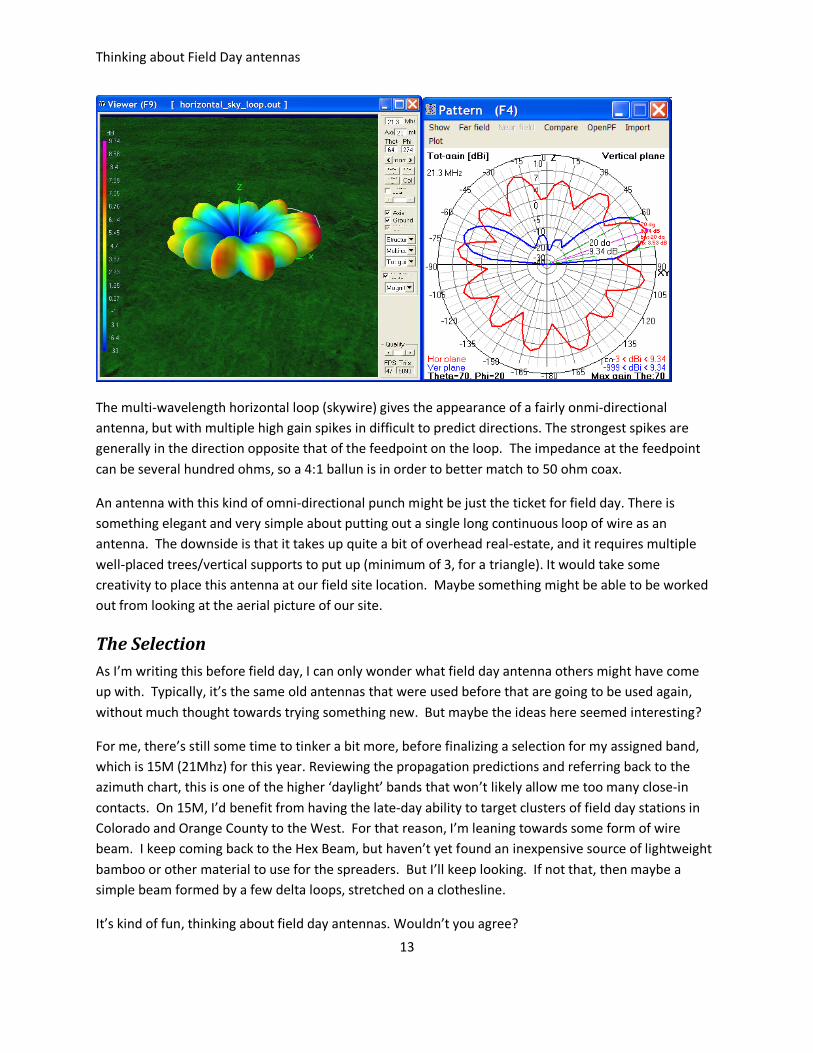
Horizontal multi-wavelength loop Taking the one wavelength vertical triangle or rectangle and putting it on its side to create a horizontal loop is often referred to as a "cloud warmer", good for NVIS and close-in communications (assuming low enough frequency, so that the ionosphere will reflect it back). However, increasing the perimeter length of the horizontal loop to multiple wavelengths ends up not as a cloud warmer, but as an antenna with a strong gain pattern in many horizontal directions, as shown in the following 4nec2 plots.
Thinking about Field Day antennas
13
The multi-wavelength horizontal loop (skywire) gives the appearance of a fairly onmi-directional antenna, but with multiple high gain spikes in difficult to predict directions. The strongest spikes are generally in the direction opposite that of the feedpoint on the loop. The impedance at the feedpoint can be several hundred ohms, so a 4:1 ballun is in order to better match to 50 ohm coax.
An antenna with this kind of omni-directional punch might be just the ticket for field day. There is something elegant and very simple about putting out a single long continuous loop of wire as an antenna. The downside is that it takes up quite a bit of overhead real-estate, and it requires multiple well-placed trees/vertical supports to put up (minimum of 3, for a triangle). It would take some creativity to place this antenna at our field site location. Maybe something might be able to be worked out from looking at the aerial picture of our site.
The Selection As I’m writing this before field day, I can only wonder what field day antenna others might have come up with. Typically, it’s the same old antennas that were used before that are going to be used again, without much thought towards trying something new. But maybe the ideas here seemed interesting?
For me, there’s still some time to tinker a bit more, before finalizing a selection for my assigned band, which is 15M (21Mhz) for this year. Reviewing the propagation predictions and referring back to the azimuth chart, this is one of the higher ‘daylight’ bands that won’t likely allow me too many close-in contacts. On 15M, I’d benefit from having the late-day ability to target clusters of field day stations in Colorado and Orange County to the West. For that reason, I’m leaning towards some form of wire beam. I keep coming back to the Hex Beam, but haven’t yet found an inexpensive source of lightweight bamboo or other material to use for the spreaders. But I’ll keep looking. If not that, then maybe a simple beam formed by a few delta loops, stretched on a clothesline.
It’s kind of fun, thinking about field day antennas. Wouldn’t you agree?