third function valve kit #380-149a installation instructionsassembly instructions 2 third function...
TRANSCRIPT

For B2320 Kubota Tractors with LA304 Loader,B2620 Kubota Tractors with LA364 Loader, andB2301 & B2601 Kubota Tractors with LA434 Loader
Manual No. 380-151M
Third Function Valve Kit #380-149A Installation Instructions
Figure 1
Notes
1. This manual is written with the assumption that the tractor is not supplied with rear remotes or backhoe.
2. This valve kit is designed to operate hydraulic cylinders.
3. For further assistance write to:
Land Pride Service DepartmentP.O. Box 5060
Salina, Ks. 67402-5060E-mail address: [email protected]
Assembly InstructionsAssembly Instructions
Initial Preparations1. Park tractor on a flat surface, place gear shift lever in
park, turn off engine, and remove ignition key.
Valve AssemblyRefer to Figure 1 & Figure 2:1. Attach valve assembly support bracket (#1) to
existing holes “C” on right-hand side of loader frame with M18-2.5 x 100 bolts (#7), 3-1/4" long tube (#3), 3-1/2" long tube (#4), flat washers (#11), and nuts (#9) as shown. Tighten nuts (#9) to the correct torque.
2. Route hydraulic hoses (#16 & #22) under the tractor platform and rearward toward the loader valve.
37026113 9
C
1
7
114 97
For color photos, visit https://dealers.landpride.com/en/12036/dealer-training
and look for “Third Function Valves.”
© Copyright 2019 Printed 5/3/19
Figure 2
Connect Hydraulic Hoses to Power Beyond Ports
1. Place chocks in front and back of tractor's left rear wheel.
2. Loosen lug nuts on right rear wheel. Do not remove lug nuts at this time.
3. Jack right rear wheel off the ground and place a jack stand under the right rear axle.
4. Lower right rear axle onto the jack stand. The rear wheel should be slightly off the ground. Make sure jack stand is secure and will not slip out from under the tractor axle.
5. Remove lug nuts and right rear wheel.
6. Locate and remove the steel tube that is connected to the power beyond port.
37027
Right-Hand Side
Left-Hand Side
Attach to positive (+) post on the tractor battery
IMPORTANT: Land Pride recommends that your dealer connect hydraulic hoses (#16 & #22) to your tractor’s power beyond ports. Improper hook-up could cause damage to your tractor or valve.
1
Assembly Instructions
Figure 3
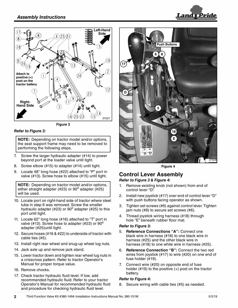
Refer to Figure 3:
7. Screw the larger hydraulic adapter (#14) to power beyond port at the loader valve until tight.
8. Screw elbow (#15) to adapter (#14) until tight.
9. Locate 48" long hose (#22) attached to “P” port in valve (#13). Screw hose to elbow (#15) until tight.
10. Locate port on right-hand side of tractor where steel tube in step 6 was removed. Screw the smaller hydraulic adapter (#23) or 90o adapter (#25) to this port until tight.
11. Locate 62" long hose (#16) attached to “T” port in valve (#13). Screw hose to adapter (#23) or 90o adapter (#25)until tight.
12. Secure hoses (#16 & #22) to underside of tractor with cable ties (#5).
13. Install right rear wheel and snug-up wheel lug nuts.
14. Jack axle up and remove jack stand.
15. Lower tractor down and tighten rear wheel lug nuts in a crisscross pattern. Refer to tractor Operator's Manual for proper torque value.
16. Remove chocks.
17. Check tractor hydraulic fluid level. If low, add recommended hydraulic fluid. Refer to your tractor Operator's Manual for recommended hydraulic fluid and procedure for checking hydraulic fluid level.
37027
Right-Hand Side
Left-Hand Side
Attach to positive (+) post on the tractor battery
NOTE: Depending on tractor model and/or options, the seat support frame may need to be removed to performing the following steps.
NOTE: Depending on tractor model and/or options, either straight adapter (#23) or 90o adapter (#25) will be used.
Third Function Valve Kit #380-149A Installation Instructions Manu2
Figure 4
Control Lever AssemblyRefer to Figure 3 & Figure 4:1. Remove existing knob (not shown) from end of
control lever “D”.
2. Install new joystick (#17) over end of control lever “D” with push buttons facing operator as shown.
3. Tighten set screws (#6) against control lever. Tighten jam nuts (#8) to secure set screws (#6).
4. Thread joystick wiring harness (#18) through hole “E” beneath rubber floor mat.
Refer to Figure 3:5. Reference Connections “A”: Connect one
black wire in harness (#18) to one black wire in harness (#25) and the other black wire in harness (#18) to one white wire in harness (#25).
6. Reference Connection “B”: Connect the two red wires from joystick (#17) to wire (#20) on one end of fuse holder (#19).
7. Connect wire (#20) on opposite end of fuse holder (#19) to the positive (+) post on the tractor battery.
Refer to Figure 4:8. Secure wiring with cable ties (#5) as needed.
37028
17
6 8
D
5
E
18
Push Buttons
al No. 380-151M 5/3/19
Assembly Instructions
Figure 5
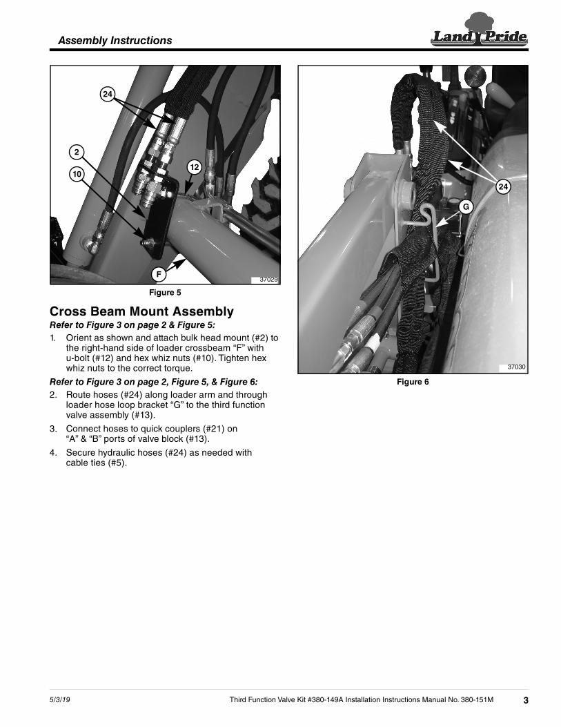
Cross Beam Mount AssemblyRefer to Figure 3 on page 2 & Figure 5:1. Orient as shown and attach bulk head mount (#2) to
the right-hand side of loader crossbeam “F” with u-bolt (#12) and hex whiz nuts (#10). Tighten hex whiz nuts to the correct torque.
Refer to Figure 3 on page 2, Figure 5, & Figure 6:2. Route hoses (#24) along loader arm and through
loader hose loop bracket “G” to the third function valve assembly (#13).
3. Connect hoses to quick couplers (#21) on “A” & “B” ports of valve block (#13).
4. Secure hydraulic hoses (#24) as needed with cable ties (#5).
37029
2
1210
24
F
5/3/19 Third Function Valv
Figure 6
37030
24
G
e Kit #380-149A Installation Instructions Manual No. 380-151M 3

Corporate Office: P.O. Box 5060Salina, Kansas 67402-5060 USA
www.landpride.com