this document, concerning the energy conservation program
TRANSCRIPT

This document, concerning the Energy Conservation Program: Energy Conservation
Program: Test Procedures for Central Air Conditioners and Heat Pumps, is a rulemaking
action issued by the Department of Energy. Though it is not intended or expected, should
any discrepancy occur between the document posted here and the document published in
the Federal Register, the Federal Register publication controls. This document is being
made available through the Internet solely as a means to facilitate the public's access to
this document.”

1
[6450-01-P]
DEPARTMENT OF ENERGY
10 CFR Parts 429 and 430
[Docket No. EERE-2009-BT-TP-0004]
RIN 1904-AB94
Energy Conservation Program: Test Procedures for Central Air Conditioners and Heat
Pumps
AGENCY: Office of Energy Efficiency and Renewable Energy, Department of Energy.
ACTION: Final rule.
SUMMARY: On November 9, 2015, the U.S. Department of Energy (DOE) issued a
supplemental notice of proposed rulemaking (SNOPR) to amend the test procedure for central air
conditioners and heat pumps. That proposed rulemaking serves as the basis for the final rule.
The final rule, in addition to satisfying the agency’s obligation to periodically review its test
procedures for covered equipment, amends specific certification, compliance, and enforcement
provisions related to this product. In the final rule DOE makes the following amendments to the
current test procedure: a new basic model definition as it pertains to central air conditioners and
heat pumps and revised requirements for represented values; revised alternative efficiency
determination methods; termination of active waivers and interim waivers; procedures to
determine off mode power consumption; changes to the test procedure that would improve test

2
repeatability and reduce test burden; and clarifications to ambiguous sections of the test
procedure intended also to improve test repeatability and reproducibility Some of these
amendments also include incorporation by reference of updated industry standards.
DATES: The effective date of this rule is [INSERT DATE 30 DAYS AFTER DATE OF
PUBLICATION IN THE FEDERAL REGISTER]. The final rule changes will be mandatory
for representations of efficiency starting [INSERT DATE 180 DAYS AFTER DATE OF
PUBLICATION IN THE FEDERAL REGISTER]. The incorporation by reference of certain
publications listed in this rule was approved by the Director of the Federal Register on [INSERT
DATE 30 DAYS AFTER DATE OF PUBLICATION IN THE FEDERAL REGISTER].
ADDRESSES: The docket, which includes Federal Register notices, public meeting attendee
lists and transcripts, comments, and other supporting documents/materials, is available for
review at regulations.gov. All documents in the docket are listed in the regulations.gov index.
However, some documents listed in the index, such as those containing information that is
exempt from public disclosure, may not be publicly available.
A link to the docket web page can be found at:
www1.eere.energy.gov/buildings/appliance_standards/rulemaking.aspx/ruleid/72. This web
page will contain a link to the docket for this notice on the regulations.gov site. The
regulations.gov web page will contain simple instructions on how to access all documents,
including public comments, in the docket.
For further information on how to review the docket, contact Ms. Brenda Edwards at
(202) 586-2945 or by email: [email protected].
3
FOR FURTHER INFORMATION CONTACT:
Ashley Armstrong, U.S. Department of Energy, Office of Energy Efficiency and
Renewable Energy, Building Technologies Program, EE-2J, 1000 Independence Avenue, SW.,
Washington, DC 20585-0121. Telephone: (202) 586–6590. Email:
Johanna Jochum, U.S. Department of Energy, Office of the General Counsel, GC-33,
1000 Independence Avenue, SW., Washington, DC, 20585-0121. Telephone: (202) 287-6307.
E-mail: [email protected].
For further information on how to submit a comment, review other public comments and
the docket, or participate in the public meeting, contact Ms. Brenda Edwards at (202) 586-2945
or by email: [email protected].
SUPPLEMENTARY INFORMATION: This final rule incorporates by reference into
part 430 specific sections, figures, and tables in the following industry standards:
1) ANSI/AHRI 210/240-2008 with Addenda 1 and 2, (“AHRI 210/240-2008”): 2008
Standard for Performance Rating of Unitary Air-Conditioning & Air-Source Heat Pump
Equipment, ANSI approved 27 October 2011;
2) ANSI/AHRI 1230-2010 with Addendum 2, (“AHRI 1230-2010”): 2010 Standard for
Performance Rating of Variable Refrigerant Flow (VRF) Multi-Split Air-Conditioning and Heat
Pump Equipment, ANSI approved August 2, 2010;
Copies of AHRI 210/240-2008 and AHRI 1230-2010 can be obtained from the Air-
Conditioning, Heating, and Refrigeration Institute, 2111 Wilson Boulevard, Suite 500, Arlington,

4
VA 22201, USA, 703-524-8800, or by going to
http://www.ahrinet.org/site/686/Standards/HVACR-Industry-Standards/Search-Standards .
3) ANSI/ASHRAE 23.1-2010, (“ASHRAE 23.1-2010”): Methods of Testing for Rating
the Performance of Positive Displacement Refrigerant Compressors and Condensing Units that
Operate at Subcritical Temperatures of the Refrigerant, ANSI approved January 28, 2010;
4) ANSI/ASHRAE Standard 37-2009, (“ANSI/ASHRAE 37-2009”), Methods of Testing
for Rating Electrically Driven Unitary Air-Conditioning and Heat Pump Equipment, ANSI
approved June 25, 2009;
5) ANSI/ASHRAE 41.1-2013, (“ANSI/ASHRAE 41.1-2013”): Standard Method for
Temperature Measurement, ANSI approved January 30, 2013;
6) ANSI/ASHRAE 41.6-2014, (“ASHRAE 41.6-2014”): Standard Method for Humidity
Measurement, ANSI approved July 3, 2014;
7) ANSI/ASHRAE 41.9-2011, (“ASHRAE 41.9-2011”): Standard Methods for Volatile-
Refrigerant Mass Flow Measurements Using Calorimeters, ANSI approved February 3, 2011
8) ANSI/ASHRAE 116-2010, (“ASHRAE 116-2010”): Methods of Testing for Rating
Seasonal Efficiency of Unitary Air Conditioners and Heat Pumps, ANSI approved February 24,
2010.
9) ANSI/ASHRAE 41.2-1987 (Reaffirmed 1992), (“ASHRAE 41.2-1987 (RA 1992)”):
“Standard Methods for Laboratory Airflow Measurement”, ANSI approved October 1, 1987.
Copies of ASHRAE 23.1-2010, ANSI/ASHRAE 37-2009, ANSI/ASHRAE 41.1-2013,
ASHRAE 41.6-2014, ASHRAE 41.9-2011, ASHRAE 116-2010, and ASHRAE 41.2-1987 (RA
1992) can be purchased from ASHRAE’s website at https://www.ashrae.org/resources--
publications.

5
10) ANSI/AMCA 210-2007, ANSI/ASHRAE 51-2007, (“AMCA 210-2007”) Laboratory
Methods of Testing Fans for Certified Aerodynamic Performance Rating, August 17, 2007;
Copies of AMCA 210-2007 can be purchased from AMCA’s website at
http://www.amca.org/store/index.php.
For a further discussion of these standards, see section IV.N.
Table of Contents
I. Authority and Background A. Authority B. Background
II. Summary of the Final Rule III. Discussion
A. Definitions, Testing, Represented Values, and Compliance of Basic Models of Central Air Conditioners and Heat Pumps
1. Basic Model Definition 2. Additional Definitions 3. Determination of Represented Values 4. Compliance with Federal (National or Regional) Standards 5. Certification Reports 6. Represented Values 7. Product-Specific Enforcement Provisions
B. Alternative Efficiency Determination Methods 1. General Background 2. Terminology 3. Elimination of the Pre-Approval Requirement 4. AEDM Validation 5. AEDM Verification Testing 6. Failure to Meet Certified Represented Values 7. Action Following a Determination of Noncompliance 8. AEDM for Off Mode
C. Waiver Procedures 1. Air-to-Water Heat Pumps and Air Conditioners 2. Clarification of the Test Procedure Pertaining to Multi-Circuit Products 3. Clarification of the Test Procedure Pertaining to Multi-Blower Products
D. Measurement of Off Mode Power Consumption 1. Test Temperatures 2. Calculation and Weighting of P1 and P2

6
3. Time Delay Credit and Removal of Calculations for Off Mode Energy Consumption and Annual Performance Factor 4. Impacts on Product Reliability 5. Off Mode Power Consumption for Intelligent Compressor Heat Control 6. Off Mode Test Voltage for Dual-Voltage Units 7. Off Mode Test Tolerance 8. Organization of Off Mode Test Procedure 9. Certification 10. Compliance Dates
E. Test Repeatability Improvement and Test Burden Reduction 1. Indoor Fan Speed Settings for Blower Coil or Single-Package Systems 2. Air Volume Rate Adjustment for Coil-Only Systems 3. Requirements for the Refrigerant Lines and Mass Flow Meter 4. Outdoor Room Temperature Variation 5. Method of Measuring Inlet Air Temperature on the Outdoor Side 6. Requirements for the Air Sampling Device 7. Variation in Maximum Compressor Speed with Outdoor Temperature 8. Refrigerant Charging Requirements 9. Alternative Arrangement for Thermal Loss Prevention for Cyclic Tests 10. Test Unit Voltage Supply 11. Coefficient of Cyclic Degradation 12. Break-in Periods Prior to Testing 13. Industry Standards that are Incorporated by Reference 14. References to ASHRAE 116-1995 (RA 2005) 15. Additional Changes Based on AHRI 210/240-Draft 16. Damping Pressure Transducer Signals 17. Clarify Inputs for the Demand Defrost Credit Equation 18. Improving Test Consistency Associated with Indoor Unit Air Inlet Geometry
F. Clarification of Test Procedure Provisions 1. Manufacturer Consultation 2. Incorporation by Reference of AHRI 1230-2010 3. Replacement of the Informative Guidance Table for Using the Federal Test Procedure 4. Clarifying the Definition of a Mini-Split System 5. Clarifying the Definition of a Multi-Split System 6. Clarifying the Housing for Uncased Coil 7. Test Procedure Reprint
G. Additional Comments from Interested Parties 1. Wet Coil Performance 2. Barometric Pressure Correction 3. Inlet Screen
H. Compliance with other Energy Policy and Conservation Act Requirements 1. Dates 2. Measured Energy Use 3. Test Burden 4. Potential Incorporation of International Electrotechnical Commission Standard 62301 and International Electrotechnical Commission Standard 62087

7
IV. Procedural Issues and Regulatory Review A. Review Under Executive Order 12866 B. Review Under the Regulatory Flexibility Act C. Review Under the Paperwork Reduction Act of 1995 D. Review Under the National Environmental Policy Act of 1969 E. Review Under Executive Order 13132 F. Review Under Executive Order 12988 G. Review Under the Unfunded Mandates Reform Act of 1995 H. Review Under the Treasury and General Government Appropriations Act, 1999 I. Review Under Executive Order 12630 J. Review Under the Treasury and General Government Appropriations Act, 2001 K. Review Under Executive Order 13211 L. Review Under Section 32 of the Federal Energy Administration Act of 1974 M. Congressional Notification N. Description of Materials Incorporated by Reference
V. Approval of the Office of the Secretary
I. Authority and Background
A. Authority
Title III, Part B1 of the Energy Policy and Conservation Act of 1975 (“EPCA” or “the
Act”), Public Law 94-163 (42 U.S.C. 6291-6309, as codified) sets forth a variety of provisions
designed to improve energy efficiency and established the Energy Conservation Program for
Consumer Products Other Than Automobiles.2 These products include single-phase central air
conditioners and central air conditioning heat pumps3 with rated cooling capacities less than
65,000 British thermal units per hour (Btu/h), which are the focus of this Final Rule. (42 U.S.C.
6291(1)–(2), (21) and 6292(a)(3))
1 For editorial reasons, Part B was codified as Part A in the U.S. Code.
2 All references to EPCA in this document refer to the statute as amended through the Energy Efficiency Improvement Act of 2015, Public Law 114-11 (Apr. 30, 2015).
3 Where this notice uses the term “CAC/HP”, they are in reference specifically to central air conditioners and heat pumps as defined by EPCA.

8
Under EPCA, DOE’s energy conservation program generally consists of four parts: (1)
testing; (2) labeling; (3) Federal energy conservation standards; and (4) certification and
enforcement. The testing requirements consist of test procedures that manufacturers of covered
products must use as the basis for: (1) certifying to DOE that their products comply with
applicable energy conservation standards adopted pursuant to EPCA, and (2) making other
representations about the efficiency of those products. (42 U.S.C. 6293(c); 42 U.S.C. 6295(s))
Similarly, DOE must use these test procedures to determine whether covered products comply
with any relevant standards promulgated under EPCA. (42 U.S.C. 6295(s))
EPCA sets forth criteria and procedures DOE must follow when prescribing or amending
test procedures for covered products. (42 U.S.C. 6293(b)(3)) EPCA provides, in relevant part,
that any test procedures prescribed or amended under this section shall be reasonably designed to
produce test results which measure the energy efficiency, energy use, or estimated annual
operating cost of a covered product during a representative average use cycle or period of use,
and shall not be unduly burdensome to conduct. Id.
In addition, if DOE determines that a test procedure amendment is warranted, it must
publish proposed test procedures and offer the public an opportunity to present oral and written
comments on them. (42 U.S.C. 6293(b)(2)) Finally, in any rulemaking to amend a test
procedure, DOE must determine to what extent, if any, the amended test procedure would alter
the measured energy efficiency of any covered product as determined under the existing test
procedure. (42 U.S.C. 6293(e)(1))
The Energy Independence and Security Act of 2007 (EISA 2007), Public Law 110-140,
amended EPCA to require that, at least once every 7 years, DOE must review test procedures for
all covered products and either amend the test procedures (if the Secretary determines that
9
amended test procedures would more accurately or fully comply with the requirements of 42
U.S.C. 6293(b)(3)) or publish a notice in the Federal Register of any determination not to amend
a test procedure. (42 U.S.C. 6293(b)(1)(A))
DOE last published a test procedure final rule for central air conditioners and heat pumps
on October 22, 2007. 72 FR 59906. The existing DOE test method for central air conditioners
and heat pumps adopted pursuant to that rule appears at Title 10 of the Code of Federal
Regulations (CFR) Part 430, Subpart B, Appendix M (“Uniform Test Method for Measuring the
Energy Consumption of Central Air Conditioners and Heat Pumps”). That procedure establishes
the currently permitted means for determining energy efficiency and annual energy consumption
of these products. The amendments in this final rule will not alter the measured efficiency of
central air conditioners and heat pumps.
EISA 2007 also established that the Department’s test procedures for all covered products
must account for standby mode and off mode energy consumption. (42 U.S.C. 6295(gg)(2)(A))
For central air conditioners and heat pumps, standby mode is incorporated into the SEER metric,
while off mode power consumption is separately regulated. This final rule includes
modifications relevant to the determination of both SEER (including standby mode) and off
mode power consumption.
10 CFR 430.27 allows manufacturers to submit an application for an interim waiver
and/or a petition for a waiver granting relief from adhering to the test procedure requirements
found under 10 CFR part 430, subpart B, appendix M. For those waivers that are active,
however, 10 CFR 430.27(l) requires DOE to amend its regulations so as to eliminate any need
for the continuation of such waivers. To this end, this final rule amends the test procedure
concerning several waivers.

10
B. Background
This final rule addresses proposals and comments from three separate rulemakings, two
guidance documents, and two working groups: (1) proposals for off mode test procedures made
in earlier notices as part of this rulemaking (Docket No. EERE-2009-BT-TP-0004); (2) proposals
regarding alternative efficiency determination methods (AEDMs) (Docket No. EERE-2011-BT-
TP-0024); (3) the recommendations of the regional standards enforcement Working Group
(Regional Standards Enforcement Working Group) (Docket No. EERE-2011-BT-CE-0077); (4)
a draft guidance document related to testing and rating split systems with blower coil units
(Docket No. EERE-2014-BT-GUID-0033); (5) a draft guidance document that deals with
selecting units for testing, rating, and certifying split-system combinations, including discussion
of basic models and of condensing units and evaporator coils sold separately for replacement
installation (Docket No. EERE-2014-BT-GUID-0032); and (6) stakeholder comments from a
request for information regarding energy conservation standards as well as the recommendations
of the central air conditioner and heat pump energy conservation standards Working Group
(CAC/HP ECS Working Group) (Docket No. EERE-2014-BT-STD-0048).
1. Proposals for off mode test procedures
DOE’s initial proposals for estimating off mode power consumption in the test procedure
for central air conditioners and heat pumps were shared with the public in a notice of proposed
rulemaking published in the Federal Register on June 2, 2010 (June 2010 NOPR; 75 FR 31224)
and at a public meeting at DOE headquarters in Washington, D.C., on June 11, 2010 (Public
Meeting Transcript, Doc. ID. EERE-2009-BT-TP-0004-0005). Subsequently, DOE published a

11
supplemental notice of proposed rulemaking (SNOPR) on April 1, 2011, in response to
comments received on the June 2010 NOPR and due to the results of additional laboratory
testing conducted by DOE. (April 2011 SNOPR) 76 FR 18105, 18127. DOE received additional
comments in response to the April 2011 SNOPR and proposed an amended version of the off
mode procedure that addressed those comments in a second SNOPR on October 24, 2011
(October 2011 SNOPR). 76 FR 65616. DOE received additional comments during the comment
period of the October 24, 2011 SNOPR and the subsequent extended comment period. 76 FR
79135.
Between the April 2011 and October 2011 SNOPRs, DOE published a direct final rule
(DFR) in the Federal Register on June 27, 2011, that set forth amended energy conservation
standards for central air conditioners and central air conditioning heat pumps, including a new
standard for off mode electrical power consumption. (June 2011 DFR) 76 FR 37408. Under the
June 2011 DFR, central air conditioning and heat pump units manufactured on or after January 1,
2015, would be subject to the published standard for off mode electrical power consumption. 10
CFR 430.32(c)(6). However, DOE has issued an enforcement policy statement regarding off
mode standards for central air conditioners and central air conditioning heat pumps4 (July 2014
Enforcement Policy Statement) specifying that DOE will not assert civil penalty authority for
violation of the off mode standard until 180 days following publication of a final rule
establishing a test method for measuring off mode electrical power consumption.
2. Proposals for AEDMs
4 Available at: http://energy.gov/sites/prod/files/2014/07/f17/Enforcement%20Policy%20Statement%20-%20cac%20off%20mode.pdf (Last accessed March 30, 2015.)

12
DOE also pursued, in a request for information (RFI) published on April 18, 2011,
(AEDM RFI) (76 FR 21673) and a NOPR published on May 31, 2012, (AEDM NOPR) (77 FR
32038) revisions to its existing alternative efficiency determination methods (AEDM) and
alternative rating methods (ARM) requirements to improve the approach by which
manufacturers may use modeling techniques as the basis to certify consumer products and
commercial and industrial equipment covered under EPCA. DOE also published a final rule
regarding AEDM requirements for commercial and industrial equipment only (Commercial
Equipment AEDM FR). 78 FR 79579 (Dec. 31, 2013).
3. Regional enforcement standards Working Group & guidance documents
On June 13, 2014, DOE published a notice of intent to form a working group to negotiate
enforcement of regional standards for central air conditioners and requested nominations from
parties interested in serving as members of the Regional Standards Enforcement Working Group.
79 FR 33870. On July 16, 2014, the Department published a notice of membership announcing
the eighteen nominees that were selected to serve as members of the Regional Standards
Enforcement Working Group, in addition to two members from Appliance Standards and
Rulemaking Federal Advisory Committee (ASRAC), and one DOE representative. 79 FR 41456.
The Regional Standards Enforcement Working Group identified a number of issues related to
testing and certification that are being addressed in this rule. In addition, all nongovernmental
participants of the Regional Standards Enforcement Working Group approved the final report
contingent on upon the issuance of the final guidance on Docket No. EERE-2014-BT-GUID-
0032 0032 and Docket No. EERE-2014-BT-GUID-0033 consistent with the understanding of the
Regional Standards Enforcement Working Group as set forth in its recommendations. (Docket
No. EERE-2011-BT-CE-0077-0070, Attachment) The amendments in this final rule supplant the
13
August 19 and 20, 2014 draft guidance documents; DOE will not finalize the draft guidance
documents and instead has provided any necessary clarity through this final rule. DOE believes
the amendments are consistent with the intent of the Regional Standards Enforcement Working
Group.
4. Energy conservation standards and Working Group
On November 5, 2014, DOE published a request for information for energy conservation
standards (ECS) for central air conditioners and heat pumps (November 2014 ECS RFI). 79 FR
65603. In response, several stakeholders provided comments suggesting that DOE amend the
current test procedure.
On July 14, 2015, DOE published a notice of intent to establish the central air
conditioners and heat pumps working group (CAC/HP ECS Working Group) to negotiate a
notice of proposed rulemaking (NOPR) for energy conservation standards. 80 FR 40938. This
working group was established under ASRAC. Ultimately, the CAC/HP ECS Working Group
consisted of 15 members, including one member from ASRAC and one DOE representative. On
January 19, 2016, the CAC/HP ECS Working Group successfully reached consensus on
amended energy conservation standards and the associated compliance date for certain product
classes of central air conditioners and central air conditioning heat pumps, on limited aspects of
the proposed, amended test procedure appendix M1, and also on a handful of other
miscellaneous issues related to the standards rulemaking as well as to this test procedure final
rule. (ASRAC Working Group Term Sheet, Docket No. EERE-2014-BT-STD-0048, No. 0076)
5. Current rulemaking
Prior to the conclusion of the CAC/HP ECS Working Group, on November 9, 2015, DOE
published a third supplemental notice of proposed rulemaking (November 2015 SNOPR) for the

14
test procedure of central air conditioners and heat pumps. 80 FR 69278. The SNOPR responded
to relevant comments from the guidance documents and rulemaking dockets discussed in this
section.
This final rule addresses certain comments received in response to the November 2015
SNOPR. Some of the provisions of the SNOPR, particularly related to changes proposed for
appendix M1, will be addressed in a separate notice. This final rule, along with the separate final
rule addressing Appendix M1, will fulfill DOE’s obligation to periodically review its test
procedures under 42 U.S.C. 6293(b)(1)(A).
II. Summary of the Final Rule
This final rule clarifies aspects of DOE’s test procedure for central air conditioners and
heat pumps to improve the consistency and accuracy of the results generated when using that
procedure. The rule primarily clarifies how to test for compliance with the current energy
conservation standards. The rule also amends certain certification, compliance, and enforcement
provisions. While the changes adopted in this rulemaking may impact test burden in certain
cases, as discussed in section III.H.3, DOE has determined that this final rule will not change the
measured energy efficiency of central air conditioners and heat pumps when compared to the
current test procedure. Any proposed amendments that would change the measured energy
efficiency will be addressed as part of the new appendix M1, in a separate notice, which will be
used in conjunction with amended standards.
DOE revises the basic model definition, adds additional definitions for clarity, makes
certain revisions to the testing requirements for determination of represented values, adds certain

15
certification reporting requirements, revises requirements for determination of represented
values, and adds product-specific enforcement provisions.
DOE updates requirements for Alternative Rating Methods (ARMs) used to determine
performance metrics for central air conditioners and heat pumps based on the regulations for
Alternative Efficiency Determination Methods (AEDMs) that are used to estimate performance
for commercial HVAC equipment. Specifically, for central air conditioners and heat pumps,
DOE makes the following amendments: (1) revising the nomenclature regarding ARMs; (2)
rescinding DOE’s pre-approval of an ARM prior to use; (3) creating AEDM validation
requirements; (4) revising the AEDM verification testing process; (5) specifying actions a
manufacturer could take following a verification test failure; and (6) clarifying consequences to
manufacturers for invalid represented values.
DOE revises the test procedure such that tests of multi-circuit products, triple-capacity
northern heat pump products, and multi-blower products can be performed without the need of
an interim waiver or a waiver. Existing interim waivers and waivers for these products, as
applicable, regarding these products will terminate 180 days after publication of this final rule.
DOE also terminates the existing waivers for air-to-water heat pump products integrated
with domestic water heating because, as discussed in section III.C.1, DOE has determined that
these waivers are not valid because they do not provide a method for measurement of the
efficiency metrics used to determine compliance with applicable standards.
DOE adopts test methods and calculations for off mode power that do not impact the
measured energy with respect to the current energy conservation standard. Specifically, the
adopted test procedure includes the following:

16
(1) Provision of an option to conduct the off mode tests in a temperature-controlled room
rather than a psychrometric room;
(2) Elimination of ambient condition requirements for units whose off mode power
consumption can be measured without control of ambient temperature;
(3) Alteration of the off mode multiplier for modulated compressors;
(4) Addition of requirements on the heating season off mode power measurement for
units having a crankcase heater whose controls cycle or vary crankcase heater power
over time;
(5) Clarification of test sample set-up and power measurement testing methodology and
components;
(6) Addition of requirement to eliminate the time delay effect on the off mode power
measurement; and
(7) Elimination of the condition where P2 is equal to zero in the off mode power
consumption calculation.
In this final rule DOE also improves the repeatability/reproducibility and reduces the test
burden of the test procedure. Specifically, DOE amends the following:
(1) Clarification of fan speed settings;
(2) Clarification of insulation requirements for refrigerant lines and addition of a
requirement for insulating mass flow meters;
(3) Addition of a requirement to demonstrate inlet air temperature uniformity for the
outdoor unit using thermocouples;

17
(4) Addition of a requirement that outdoor air conditions be measured using sensors
measuring the air captured by the air sampling device(s) rather than the temperature
sensors located in the air stream approaching the inlets;
(5) Addition of a requirement that the air sampling device and the tubing that transfers
the collected air to the dry bulb temperature sensor be at least two inches from the
test chamber floor, and a requirement that humidity measurements be based on dry
bulb temperature measurements made at the same location as the corresponding wet
bulb temperature measurements used to determine humidity;
(6) Clarification of maximum speed for variable-speed compressors;
(7) Addition of requirements that improve consistency of refrigerant charging
procedures;
(8) Allowance of an alternative arrangement for cyclic tests to replace the currently-
required damper in the inlet portion of the indoor air ductwork for single-package
ducted units;
(9) Clarification of the proper supply voltage for testing;
(10) Revision of the determination of the coefficient of cyclic degradation (CD);
(11) Option for a break-in period of up to 20 hours;
(12) Update of references to industry standards where appropriate;
(13) Inclusion of information from the draft AHRI 210/240;
(14) Addition of provisions regarding damping of pressure transducer signals to avoid
exceeding test operating tolerances due to high frequency fluctuations;
(15) Clarification of inputs for the demand defrost credit equation; and
(16) Improvement of test consistency associated with indoor unit air inlet geometry.

18
DOE also provides additional detail and specificity with respect to several provisions.
Specifically, DOE adds reference to an industry standard for testing variable refrigerant flow
multi-split systems; replaces the informative guidance table for using the test procedure; clarifies
the definition of multi-split systems; clarifies the definition of mini-split systems, which DOE
now calls multi-head mini-split systems; and clarifies the housing for uncased coils.
Lastly, DOE addresses comments received from stakeholders in response to the
November 2015 SNOPR that were unrelated to any of DOE’s proposals. Specifically, this
includes the following:
(1) Water condensation metric;
(2) Barometric pressure correction ; and
(3) Inlet screen.
Given the difficulty of writing amendatory instructions to implement the many small
changes throughout appendix M, DOE has provided a full re-print of appendix M in the
regulatory text of this final rule.
DOE revises the test procedure in this final rule as reflected in the revised Appendix M to
Subpart B of 10 CFR Part 430 effective on [INSERT DATE 30 DAYS AFTER DATE OF
PUBLICATION IN THE FEDERAL REGISTER]. The amended test procedure is
mandatory for representations of efficiency as of [INSERT DATE 180 DAYS AFTER DATE
OF PUBLICATION IN THE FEDERAL REGISTER].
III. Discussion
This final rule amends the test procedure for central air conditioners and heat pumps in
appendix M to subpart B of Part 430 and adds new product-specific certification and

19
enforcement provisions in 10 CFR 429.12, 429.16, 429.70, and 429.134. The rule also amends
certain definitions found in 10 CFR 430.2 and updates certain materials incorporated by
reference in 10 CFR 430.3.
In response to the November 2015 SNOPR, the following 25 interested parties submitted
written comments: Advanced Distributor Products LLC; Air-Conditioning, Heating, and
Refrigeration Institute (AHRI); American Council for an Energy Efficient Economy (ACEEE);
Appliance Standards Awareness Project (ASAP); First Co.; Goodman Global, Inc.; Heating, Air
Conditioning & Refrigeration Distributors International (HARDI); Ingersoll Rand; Johnson
Controls Inc. (JCI); Lennox International Inc; LG Electronics U.S.A., Inc; Mitsubishi Electric
Cooling & Heating; Natural Resources Defense Council (NRDC); Nortek Global HVAC;
Northwest Energy Efficiency Alliance (NEEA); Northwest Power and Conservation Council
(NPCC); Pacific Gas and Electric Company (PG&E); Rheem Manufacturing Company (Rheem);
San Diego Gas and Electric Company (SDG&E); Southern California Edison (SCE); Southern
California Gas Company (SCG); Unico, Inc.; United Refrigeration, Inc. (URI); United
Technologies Climate, Controls & Security (UTC), also known as Carrier Corporation. NEEA
and NPCC submitted a joint comment. PG&E, SDG&E, SCG, and SCE, hereafter referred to as
the California Investor-Owned Utilities (California IOUs), also submitted a joint comment.
ACEEE, ASAP, and NRDC, hereafter referred to as the Efficiency Advocates, also submitted a
joint comment.
Interested parties provided comments on a range of issues, including those DOE
identified in the November 2015 SNOPR, as well as several other pertinent issues related to
DOE's proposal. Commenters also offered thoughts on further opportunities to improve the
clarity of the test procedure. These issues, as well as DOE’s responses to them and the resulting

20
changes to DOE’s proposal, are discussed in the subsequent sections. A parenthetical reference
at the end of a comment quotation or paraphrase provides the location of the item in the public
record.5
A. Definitions, Testing, Represented Values, and Compliance of Basic Models of Central Air
Conditioners and Heat Pumps
On August 19 and 20, 2014, DOE issued two draft guidance documents regarding the test
procedure for central air conditioners and heat pumps. One guidance document dealt with
testing and rating split systems with blower coil indoor units (Docket No. EERE-2014-BT-
GUID-0033); and the other dealt more generally with selecting units for testing, rating, and
certifying split-system combinations, including discussion of basic models and of condensing
units and evaporator coils sold separately for replacement installation (Docket No. EERE-2014-
BT-GUID-0032). The comments in response to these draft guidance documents were discussed
in the November 2015 SNOPR. DOE proposed changes to the substance of the draft guidance
that reflects the comments received as well as the recommendations of the Regional Standards
Enforcement Working Group (Docket No. EERE-2011-BT-CE-0077-0070, Attachment). DOE
makes additional modifications in this final rule in response to comment on the November 2015
SNOPR as well as the recommendations of the CAC/HP ECS Working Group (Docket No.
Docket No. EERE-2014-BT-STD-0048, No. 76). The adopted changes supplant the two draft
guidance documents; DOE will not finalize the draft guidance documents and has instead
provided any necessary clarity through this final rule.
5 The parenthetical reference provides a reference for information located in the docket of DOE’s rulemaking to amend the test procedures for central air conditioners and heat pumps. (Docket No. EERE-2009-BT-TP-0004, which is maintained at http://www.regulations.gov/#!docketDetail;D=EERE-2009-BT-TP-0004). The references are arranged as follows: (commenter name, comment docket ID number, page of that document).

21
1. Basic Model Definition
In the November 2015 SNOPR, DOE proposed modifying its basic model definition for
central air conditioners and heat pumps. 80 FR at 69282-4 (Nov. 9, 2015). Under DOE’s
proposal, manufacturers could consider each individual model/combination its own basic model,
or manufacturers could assign all individual models of the same single-package system or all
individual combinations using the same model of outdoor unit (for outdoor unit manufacturers
(OUM)) or model of indoor unit (for independent coil manufacturers (ICM)) to the same basic
model. DOE proposed to further define (for both single-package units and split systems) the
physical characteristics necessary to assign individual models or combinations to the same basic
model. 80 FR 69278, 69282-83 (Nov. 9, 2015).
DOE proposed that, if a manufacturer chooses to assign each individual model or
combination to its own basic model, the manufacturer must test each individual
model/combination—and that an AEDM could not be applied. 80 FR 69278, 69283 (Nov. 9,
2015). If manufacturers assign all individual combinations of a model of outdoor unit (for
OUMs) or model of indoor unit (for ICMs) to a single basic model, DOE further proposed that
each individual combination within a basic model must be certified with a rating determined for
that individual combination. However, only one individual combination in each basic model
would have to be tested (see section III.A.3.a), while the others may be rated using an AEDM.
This option reduces testing burden but increases risk. Specifically, if any one of the combinations
within a basic model fails to meet the applicable standard, then all of the combinations within the
basic model fail, and the entire basic model must be taken off the market. 80 FR 69278 at 69283
(Nov. 9, 2015).
Comments on these proposals are discussed in the following sections.

22
a. Basic Model Framework
The Joint Advocates of ACEEE, NRDC and ASAP (“Joint Advocates”) supported the
proposed changes to the definition of a basic model and related testing and certification
requirements. The Joint Advocates stated that they believe that the clarified testing requirements
would reduce testing burden on manufacturers. (ACEEE, NRDC and ASAP, No. 72 at p. 1)
Nortek supported DOE’s proposal that manufacturers would have a choice in how to assign
individual models or combinations to basic models. (Nortek, No. 58 at p. 3) ADP and Lennox
supported the use of the basic model as the basis for any enforcement action as discussed in
Section III.A.8 (80 FR 69278, 69297 (Nov. 9, 2015)) and the proposed 10 CFR 429. (ADP, No.
59 at p. 7; Lennox, No. 61 at p. 14)
NEEA and NPCC commented that DOE’s proposed approach that all combinations
within the basic model are deemed noncompliant if only one of the combinations within a basic
model fails does not align with the other aspects of DOE’s current proposal, in which each and
every combination has its own certified rating. (NEEA and NPCC, No. 64 at p. 2-3)
Carrier/UTC expressed the concern that if one combination amongst potentially hundreds
of combinations rated with a given outdoor unit fails then the entire basic model will be removed
from the market and claimed that it is excessively punitive. Further, Carrier/UTC recommended
a provision for saving the remaining indoor combinations of the basic model such as testing the
tested combination and one (or more) other random indoor combinations. Carrier/UTC stated
that the de-listing of the product should be limited to the combination that failed, not the entire
basic model. (Carrier/UTC, No. 62 at pp. 5-6)
NEEA and NPCC further commented that they presume that DOE’s ratings guidance of
August 19 and 20, 2014, would also be impacted by a requirement to rate all outdoor and indoor

23
unit combinations and the proposal with regard to testing-derived versus AEDM-derived ratings.
They asserted that the proposal would seem to require the rating of both coil-only and blower
coil combinations, with the choice of either using the highest sales volume combination being
tested (and all other combinations rated using an AEDM), or testing each combination as its own
basic model. (NEEA and NPCC, No. 64 at p. 2-3)
In response to NEEA and NPCC, DOE disagrees that DOE cannot make a determination
of compliance on a basic model basis simply because DOE permits the manufacturer to make
different representations for combinations within a basic model. In response to NEAA, NPCC,
and UTC/Carrier, DOE notes that it developed the proposal for the basic model framework in an
effort to balance manufacturer test burden and risk. The determination of compliance with the
standard is made at the basic model level, and the manufacturer may choose how to group
models into basic models and whether or not to make use of an AEDM for represented values of
combinations. DOE expects that the individual combinations grouped into a single basic model
would have similarities that would make validation of one of the individual model/combination’s
represented values a strong indication of the accuracy of the represented values of the other
models/combinations—if the represented values are indeed different. DOE also notes that when
manufacturers use an AEDM and DOE finds an invalid rating, manufacturers can conduct re-
testing to re-certify the individual model/combination, as described in section 429.70.
DOE also notes that, as stated in the November 2015 SNOPR, this final rule will supplant
DOE’s draft ratings guidance documents, which will not be finalized. Finally, DOE notes in
response to NEEA and NPCC that the basic model framework itself does not determine whether
both coil-only and blower coil combinations must be rated; this is further discussed in section

24
III.A.3.a. Given the support for the basic model framework voiced by many of the commenters,
DOE adopts the framework as proposed in the SNOPR.
b. General Definition Comments
AHRI and several manufacturers including UTC/Carrier, ADP, Lennox, Nortek, and
Unico agreed generally with DOE’s proposal to modify its basic model definition. (AHRI, No.
70 at p. 3; UTC/Carrier, No. 62 at p. 5-6; ADP, No. 59 at p. 7; Lennox, No. 61 at p. 14; Nortek,
No. 58 at p. 3; Unico, No. 63 at p. 4) Rheem recommended that DOE adopt the industry standard
definition for basic model, as defined by AHRI. (Rheem, No. 69 at p. 4) As described below,
several commenters requested additional modifications to DOE’s proposed definitions; these
comments are discussed below, along with revisions to the proposed definitions.
c. Split Systems Manufactured by OUMs and Single-Package Systems
For split systems manufactured by OUMs and single-package systems, AHRI, Lennox,
Ingersoll Rand, Rheem, and Nortek recommended the removal of “the auxiliary refrigeration
system components if present (e.g., expansion valve) and controls” from the proposed basic
model definition. Lennox and Nortek commented that adding these components to the definition
can greatly expand the number of basic models. (AHRI, No. 70 at p. 3; Lennox, No. 61 at p. 4;
Ingersoll Rand, No. 65 at p. 11; Rheem, No. 69 at p. 4; Nortek, No. 58 at p. 3) Additionally,
Lennox and Nortek suggested that there would not be a benefit to expanding the definition of
basic model beyond the currently accepted industry practice as outlined in AHRI’s certification
program. (Lennox, No. 61 at p. 4; Nortek, No. 58 at p. 3) DOE understands Lennox and Nortek
are referring to the concept of a “basic model group” as the term is described in the AHRI
Operations Manual for Unitary Small Air-Conditioners and Air-Source Heat Pumps, in section
1.5, “Basic Model Groups (BMGs).”

25
After reviewing the comments, DOE acknowledges that while use of different auxiliary
refrigeration system components may impact measured performance, it may not do so
significantly—for example, measurements made using two different thermostatic expansion
valves that both maintain the same superheat should not be different.. In an effort to balance
manufacturer test burden with the regulatory needs of the program to establish an appropriate
basic model definition, DOE has not included the phrase “auxiliary refrigeration system
components if present (e.g., suction accumulator, reversing valve, expansion valve) and controls”
in the “basic model” definition for split systems manufactured by OUMs or for single-package
systems. DOE notes, however, that each manufacturer is responsible for minor variations in
efficiency differences resulting from such changes in design.
For the definition of a basic model for OUMs, Goodman agreed with DOE's overall
direction. However, Goodman commented that DOE’s proposed definition was too rigid and
would not provide enough design flexibility to manufacturers. Specifically, Goodman cited the
importance of the ability for a manufacturer to vary many aspects of its outdoor coils (e.g., style
and fin depth) and to source components, such as compressors, from multiple component
manufacturers. Goodman asserted that this flexibility in design would allow manufacturers to
provide combinations that optimize their product offering to consumers, while still yielding
similar performance and therefore meriting classification under a single basic model. Goodman
suggested revised basic model definitions for split systems manufactured by OUMs and single-
package systems in which the list of parameters affecting performance (e.g., compressor and
outdoor coil properties) that had been proposed to define a distinct model be instead provided as
guidance for the OUM to consider when deciding whether two variations of a design should have
the same model number. (Goodman, No. 73 at pp. 2-3)

26
In response to Goodman, DOE recognizes the importance of allowing manufacturers
flexibility in design. DOE agrees with Goodman that, for instance, using compressors from
different compressor manufacturers in two different models should not require the manufacturer
to classify these models as two separate basic models, if the models can still reasonably be
described as having “essentially identical characteristics.” However, DOE believes that
Goodman’s suggested revised definitions, by providing guidance but no requirements, would
allow widely varying characteristics under the same model of outdoor unit or single-package
unit. Rather than moving to definitions that provide flexibility limited only by guidance, DOE
has instead modified the definitions to allow some design flexibility, while assuring that a large
departure from a given design would require that the OUM establish a new basic model. In the
definitions established in this final rule for basic model for split systems manufactured by OUMs
and single-package systems, DOE has removed certain requirements proposed in the November
2015 SNOPR, and added tolerances for the remaining requirements. Specifically, these
modifications from the proposal include: (1) establishing a five percent tolerance for compressor
displacement, capacity, and power input; (2) removing requirements for several outdoor coil
parameters; (3) adding a five percent tolerance to the face area and total fin surface area of the
outdoor coil; (4) adding a ten percent tolerance on outdoor airflow, and (5) for single-package
systems, allowing a ten percent tolerance on indoor airflow and a twenty percent tolerance on
power input to the indoor fan motor.
In the basic model definition proposed in the November 2015 SNOPR for split systems
manufactured by OUMs and single-package systems, DOE specified that all individual models
or combinations in a basic model must have the same or comparably performing compressor(s)
with the “same displacement rate (volume per time) and same capacity and power input when

27
tested under the same operating conditions.” 80 FR 69278, 69341 (Nov. 9, 2015). In order to
promote design flexibility, DOE is adopting less stringent requirements in the basic model
definition amended in this final rule by adding a five percent tolerance to the displacement rate
and capacity and power input. DOE’s research suggests that comparable compressors made by
different manufacturers vary by less than two percent in displacement rate and capacity and
power input when tested under the same conditions. Therefore, DOE believes that a five percent
tolerance allows manufacturers the option to use comparably performing compressors from
different manufacturers in models without having to classify the models as separate basic
models. Additionally, in the definition established in this final rule, DOE explains that the
tolerances on compressor parameters refer to the values rated by the compressor manufacturer,
not the performance of individual compressors.
In this final rule, DOE is adopting less stringent requirements for classifying as
comparably performing outdoor coil(s) in the basic model definition for split systems
manufactured by OUMs and single-package systems. To provide more flexibility to
manufacturers, DOE is not adopting specifications in the basic model definitions for: coil depth,
fin style (e.g., wavy, louvered), fin density (fins per inch), tube pattern, tube diameter, tube wall
thickness, and tube internal enhancement. However, DOE has added a five percent tolerance to
the face area and total fin surface area for outdoor coils. This tolerance on the outdoor coil areas
will allow manufacturers to vary their designs while achieving similar performance, such as
adding another row perpendicular to the airflow direction to the outdoor coil to compensate for
using a more energy-consuming compressor.
Additionally, DOE is adding tolerances to the requirements for classifying as comparably
performing outdoor fan(s) in the basic model definition for split systems manufactured by OUMs

28
and single-package systems. DOE is adding a ten percent tolerance on outdoor fan airflow. DOE
believes that this tolerance will allow manufacturers to make adjustments to the fans, such as
increasing the number, diameter, or design of fan blades, without classifying comparably
performing models as separate basic models.
UTC/Carrier agreed with DOE’s proposal to align the basic model definition with that
used by AHRI; however, they asserted that the list of additional reporting requirements is
excessive and burdensome. Specifically, UTC/Carrier stated that some of these components do
not affect the performance of the system, are considered proprietary, and need not be reported.
Additionally, they stated that some of these minor components may change due to sourcing
availability. UTC/Carrier recommended that DOE align the basic model exactly with AHRI’s
basic model group definition: compressor model, outdoor coil face area, and outdoor airflow, and
not require any additional data to be reported. (UTC/Carrier, No. 62 at p. 2)
For split systems manufactured by OUMs, Lennox recommended that the proposed OUM
basic model definition be revised to more closely align with industry practices and recommended
that the definition of outdoor coil be revised to protect business sensitive information. (Lennox,
No. 61 at p. 4) Specifically, Lennox requested that the definition of outdoor coil-only include the
words “same face area and depth, style.” Lennox suggested that DOE remove the remaining
specification requirements for outdoor coils so that this sensitive business information could not
be made available to the public and industry competitors through a FOIA request. (Lennox, No.
61 at pp. 3-4)
DOE acknowledges the importance of avoiding disclosure of proprietary or sensitive
business information; however, in the November 2015 SNOPR DOE did not propose any
additional certification requirements or supplemental test instruction reporting that would require

29
disclosure of these parameters about which UTC/Carrier and Lennox cited concern. 80 FR
69278, 69338-39 (Nov. 9, 2015). Requirements for reporting are limited to those items listed in
section 429.16(e), and mention of a parameter as the basis for distinguishing a model does not by
itself imply that the value of that parameter must be reported in certification reports. DOE notes
that it is not requiring that manufacturers report the sensitive information such as surface area or
coil depth for which their basic model determinations are made.
In response to UTC/Carrier, DOE recognizes that minor components may vary in
manufacturer designs based on availability from component manufacturers. However, DOE
believes that the tolerances established in this final rule (as previously discussed) around most of
the requirements in DOE’s definition of basic model allow for variation in component models
and manufacturers. DOE also believes that the requirements included in DOE’s definition of
basic model are necessary to ensure units are similar enough to be classified as the same basic
model. DOE also notes that the definition established in this final rule includes tolerances on the
compressor model ratings, outdoor coil face area, and outdoor airflow; therefore DOE’s
definition allows more flexibility for outdoor coil face area and outdoor airflow than does the
definition of a split-system model group in the AHRI Operations Manual.6
In response to Lennox, as previously discussed, DOE has removed references to fin
material, style, or density or tube thickness in the basic model definition established in this final
rule, which will provide manufacturers with more flexibility in offering a varied product offering
to consumers while limiting the testing burden.
6 AHRI’s Operations Manual for Unitary Small Air-Conditioners and Air-Source Heat Pumps (Includes Mixed-Match Coils) (Rated Below 65,000 Btu/h) Certification Program (AHRI OM 210/240—March 2015). Available at www.ahrinet.org/App_Content/ahri/files/Certification/OM%20pdfs/USE_OM.pdf (Last accessed March 31, 2016.)

30
d. Requirements for Independent Coil Manufacturers
Several commenters expressed concern about the impact of the proposed definition of
basic model on ICM test burden. Therefore comments regarding the ICM basic model definition
are addressed in the context of testing required to determine represented values in section
III.A.3.d.
e. Off-Mode
Revisions to the test procedure as stated in section III.D of this final rule enable the
determination of off mode power consumption, which reflects the operation of the contributing
components: crankcase heater and low-voltage controls. In the November 2015 SNOPR, DOE
proposed that if individual combinations that are otherwise identical are offered with multiple
options for off mode related components, manufacturers at a minimum must rate the individual
combination with the crankcase heater and controls which are the most consumptive. Under this
proposal, if a manufacturer wished to also make representations for less consumptive off mode
options for the same individual combination, the manufacturer could provide separate ratings as
long as the manufacturer differentiated the individual model numbers for these ratings. These
individual combinations would be within the same basic model. 80 FR 69278, 69284 (Nov. 9,
2015).
In their comments, NEEA and NPCC strongly supported DOE's proposal to require
manufacturers to either rate and certify all combinations using the most consumptive off-mode
power controls and systems, or to differentiate models they wish to certify with different off-
mode power controls and/or systems with different model numbers, each with its own certified
rating. (NEEA and NPCC, No. 64 at p. 4)
DOE received no other comments on this proposal and adopts it in this final rule.

31
f. Central Air Conditioner Definition
In the November 2015 SNOPR, DOE proposed to clarify that a central air conditioner or
central air conditioning heat pump may consist of: a single-package unit; an outdoor unit and one
or more indoor units (e.g., a single-split or multi-split system); an indoor unit only (rated as a
combination by an ICM with an OUM’s outdoor unit); or an outdoor unit only (with no match,
rated by an OUM with the coil specified in this test procedure). DOE proposed adding these
specifications to the definition of central air conditioner or central air conditioning heat pump in
10 CFR 430.2. In the certification reports submitted by OUMs for split systems, DOE proposed
that manufacturers must report the basic model number as well as the individual model numbers
of the indoor unit(s) and the air mover where applicable. 80 FR 69278, 69284 (Nov. 9, 2015).
Lennox and ADP expressed concern that modifying the CAC/HP definition to include
"an indoor unit" only may have significant unintended consequences with additional regulation
now applying to indoor units. They stated that the indoor unit has no heating or cooling
capability without being installed as a part of the system, that by itself, it is a component, and
that the proposed definition is factually incorrect and contradicts the DOE’s previous position
that they do not have authority to regulate components of air conditioners. Lennox recommended
DOE keep the existing definition. (Lennox, No. 61 at p. 10; ADP, No. 59 at p. 4)
DOE notes that the modification of the CAC/HP definition does not change the scope of
DOE’s product coverage and is in line with the current certification requirements for CAC/HP.
Specifically, ICMs are currently responsible for testing and certifying models of indoor units
they manufacture as part of a split-system combination. DOE received no other comment on this
topic. For these reasons, DOE is adopting the CAC/HP definition as proposed.
32
2. Additional Definitions
In the November 2015 SNOPR, in order to specify differences in the proposed basic
model definition for ICMs and OUMs, DOE proposed definitions for an ICM and an OUM. With
respect to any given basic model, a manufacturer could be an ICM or an OUM. 80 FR 69278,
69284 (Nov. 9, 2015).
DOE also proposed to define variable refrigerant flow (VRF) systems that are single-
phase and less than 65,000 Btu/h as a kind of multi-split central air conditioner and central air
conditioning heat pump system. Id.
Additionally, DOE proposed to clarify several other definitions currently in 10 CFR
430.2 with minor wording changes and move them to 10 CFR 430, Subpart B, Appendix M.
DOE also proposed to remove entirely the definitions for “condenser-evaporator coil
combination” and “coil family,” as those terms no longer appear in the proposed regulations. Id.
DOE did not receive any comments on these definitions and related changes and adopts
the proposals in this final rule.
a. Indoor Unit
In the November 2015 SNOPR, DOE proposed modifying the definition of indoor unit to read as
follows: “indoor unit transfers heat between the refrigerant and the indoor air, and consists of an
indoor coil and casing and may include a cooling mode expansion device and/or an air moving
device.” 80 FR 69278, 69284 (Nov. 9, 2015).
Goodman commented that the definition for indoor unit does not fully account for the
range of indoor units sold in the market. Specifically, Goodman stated that including the casing
in the proposed indoor unit definition is inconsistent with many industry offerings. Goodman
also suggested a new definition for indoor unit. (Goodman, No. 73 at p. 3-5)

33
AHRI and Nortek proposed a definition for indoor units that does not include casing
and/or an expansion device. AHRI and Nortek expressed concern that the uncased coil would no
longer be within the scope of regulation, which could open the doors for a loophole in the
regulation, or that manufacturers would not be able to list an uncased coil with an outdoor unit,
resulting in an illegal installation. AHRI and Nortek proposed definitions for uncased coil, cased
coil, and service coil. (AHRI, No. 70 at p. 8; Nortek, No. 58 at p. 3-4). Further, AHRI stated that
DOE should make clear that service coils will not be rated in the future. (AHRI, No. 70 at p. 8)
UTC/Carrier commented that the exclusion of uncased coils from DOE certification
represents a significant loophole as uncased coils are often installed in various new construction
scenarios and should be certified. According to UTC/Carrier, DOE should further define the
replacement component service coils that are used only when the current coils fail and are
considered service parts and, thus, should not be certified to DOE; the treatment of uncased coils
in commerce by manufacturers as service-only is problematic. (UTC/Carrier, No. 62 at p. 3)
JCI commented that, while some manufacturers use uncased service coils, others supply
service coils with casings on them. In addition, JCI commented that not all uncased coils are
service coils. According to JCI, there are product families of uncased coils very often sold for
new construction installations, or installation of new A/C systems in the northern parts of the
United States. For example, JCI noted that often in the northern United States, a new home may
be constructed with only a furnace for heating and no cooling, and that cooling may be added
later by installing an uncased coil into the ductwork itself. JCI commented that the uncased coil
market is a vital part of the northern U.S. market, and uncased coils need to be allowed to be

34
rated as valid matches with a basic outdoor model. (JCI, No. 66 at p. 12-13). JCI also suggested
definitions for uncased coil, cased coil, service coil, and indoor unit. (JCI, No. 66 at p. 13)
The California IOUs requested that DOE allow manufacturers to rate uncased coils with
outdoor condensing units. They reported that California Building Energy Efficiency Standards
(Title 24) define the replacement of any component containing refrigerant to be a system
alteration requiring verification of refrigerant charge and airflow through the coil. (see California
Code of Regulations, Title 24, Part 1, Article 1, Section 150.2(b)(1)F) The California IOUs
stated that the replacement of an indoor coil is an alteration whether the coil is cased or uncased.
DOE asserted that DOE’s proposal to define uncased coils as repair parts and to not require them
to be part of a rated model would create a compliance problem for contractors in California
because without ratings, the energy efficiency of the system with an uncased coil is not known.
The California IOUs stated that in applications where the existing coil is removed from the
existing case and replaced with a new coil, which is then connected to a new outdoor unit, the
efficiency rating is required to meet Title 24. Therefore, the California IOUs requested that DOE
allow ratings of combinations having uncased indoor coils so that compliance with Title 24 can
be verified. (California IOUs, No. 67 at p. 2)
ADP and Lennox commented that they understand the intent of excluding uncased coils
is to differentiate between indoor units used for legacy replacements and new installations, but
believe that DOE’s proposal would create a significant loophole. ADP and Lennox commented
that uncased coils are used for new installations in a significant number of markets in the upper
Midwest of the United States where a long tradition of skilled sheet metal workers exists.
Additionally, they asserted that Canada is a predominately uncased coil market and relies on
manufacturer ratings that have been certified with DOE and AHRI. Instead, ADP suggests that

35
DOE require replacement coils not subject to certification to carry a different model number than
those sold for installation as a part of new, certified systems. (ADP, No. 59 at p. 4-5; Lennox,
No. 61 at p. 10)
After consideration of the comments that uncased coils may be used for new installations
and that the exclusion of uncased coils from the indoor unit definition could result in a
significant loophole, DOE is adopting a revised definition for an indoor unit such that it “may or
may not include… (e) external cabinetry”. To distinguish newly installed cased and uncased
coils from replacement cased and uncased coils, DOE has added a definition for service coils and
explicitly excluded them in the indoor unit definition.
Indoor unit means part of a split-system air conditioner or heat pump that includes (a) an
arrangement of refrigerant-to-air heat transfer coil(s) for transfer of heat between the
refrigerant and the indoor air and (b) a condensate drain pan, and may or may not include
(c) sheet metal or plastic parts not part of external cabinetry to direct/route airflow over
the coil(s), (d) a cooling mode expansion device, (e) external cabinetry, and (f) an
integrated indoor blower (i.e. a device to move air including its associated motor). A
separate designated air mover that may be a furnace or a modular blower (as defined in
Appendix AA to the subpart) may be considered to be part of the indoor unit. A service
coil is not an indoor unit.
Service coil means an arrangement of refrigerant-to-air heat transfer coil(s) and
condensate drain pan that may or may not include sheet metal or plastic parts to
direct/route airflow over the coil(s), external cabinetry, and/or a cooling mode expansion
device, and is sold exclusively to replace an uncased coil or cased coil that has already
been placed into service and is labeled accordingly.

36
DOE also acknowledges the benefit of including definitions for both cased and uncased
coils, and adopts the following definitions:
Cased coil means a coil-only indoor unit with external cabinetry.
Uncased coil means a coil-only indoor unit without external cabinetry.
In the November 2015 SNOPR, DOE proposed to specify that if the indoor unit does not
ship with a cooling mode expansion device, the system should be tested using the device as
specified in the installation instructions provided with the indoor unit, or if no device is
specified, using a thermostatic expansion valve (TXV). 80 FR 69278, 69284 (Nov. 9, 2015).
Goodman commented that DOE should not assume the use of TXV if a metering
(expansion) device is not specified by the manufacturer. Goodman commented that the majority
of systems installed today use fixed orifice rather than TXV expansion devices. (Goodman, No.
73 at p. 3-5)
DOE agrees that many product offerings use fixed orifice or piston expansion devices as
standard equipment and that it may be more suitable to use a fixed orifice or piston device if
there are no detailed instructions provided in installation instructions regarding selection of an
expansion device. This is because a system installed in the field without such instructions may
very well perform poorly if an optimized device is not selected. Because a TXV generally is
likely to provide better performance over a range of operating conditions, DOE believes the use
of a fixed orifice is more consistent with this potential for poor field performance. Therefore,
DOE is modifying its proposal and requiring instead that a fixed orifice or piston expansion
device be used if the installation instructions do not specify a metering (expansion) device.

37
b. Blower Coil and Coil-Only Indoor Units
In the November 2015 SNOPR, DOE proposed definitions for blower coil indoor unit
and coil-only indoor unit. The motivation was to simplify the description of the test requirements
by referring to blower coil units instead of units “with an indoor fan installed” and to coil-only
units instead of units “without an indoor fan installed”.
Blower coil indoor unit means the indoor unit of a split-system central air conditioner or
heat pump that includes a refrigerant-to-air heat exchanger coil, may include a cooling-
mode expansion device, and includes either an indoor blower housed with the coil or a
separate designated air mover such as a furnace or a modular blower (as defined in
Appendix AA).
Blower coil system refers to a split system that includes one or more blower coil indoor
units.
Coil-only indoor unit means the indoor unit of a split-system central air conditioner or
heat pump that includes a refrigerant-to-air heat exchanger coil and may include a
cooling-mode expansion device, but does not include an indoor blower housed with the
coil, and does not include a separate designated air mover such as a furnace or a modular
blower (as defined in Appendix AA). A coil-only indoor unit is designed to use a
separately-installed furnace or a modular blower for indoor air movement.
Coil-only system refers to a system that includes one or more coil-only indoor units. 80
FR 69278, 69286 (Nov. 9, 2015).
ADP and UTC/Carrier agreed with the proposed definitions for blower coil and coil-only
indoor units. (ADP, No. 59 at p. 6; UTC/Carrier, No. 62 at p. 3) Lennox agreed with the
proposed definitions with the exceptions noted in other sections. (Lennox, No. 61 at p. 13) Unico

38
agreed with the coil-only indoor definition, except recommended removing the word “modular”
as there is no definition. Unico commented that the blower can be anywhere in the system.
(Unico, No. 63 at p. 2) JCI suggested definitions for air handler, blower coil, and coil-only. (JCI,
No. 66 at p. 13)
Rheem commented that the proposed definitions for blower coil and coil-only indoor
units exclude the customary practice in the Northwest United States where an uncased coil is
installed in a plenum for space-constrained installations. Rheem stated that under DOE’s
proposal, a certified rating for this system configuration would no longer be available to
consumers. Rheem noted that there are building inspectors who require an AHRI or DOE
certified combination including the evaporator coil for replacements. (Rheem, No. 69 at p. 5)
DOE acknowledges that by excluding indoor units without a casing, the customary
practice identified by Rheem would not be included. As noted in the previous section, DOE has
addressed this by expanding the indoor unit definition to include units which may or may not
have external cabinetry. The blower coil and coil-only indoor unit definitions then build on this
updated indoor unit definition. Further, DOE has removed, from both the blower coil and coil-
only indoor unit definitions, language redundant with the indoor unit definition and is adopting
the following definitions:
Blower coil indoor unit means an indoor unit either with an indoor blower housed with
the coil or with a separate designated air mover such as a furnace or a modular blower (as
defined in appendix AA to this subpart).
Coil-only indoor unit means an indoor unit without an indoor blower or separate
designated air mover. A coil-only indoor unit is designed to use a separately-installed
furnace or a modular blower for indoor air movement.

39
In response to Unico’s comment regarding “modular”, the definition explicitly refers to
the definition of “modular blower” in appendix AA. In response to JCI’s comment requesting a
definition for “air handler”, DOE feels that this is not necessary because there are few
distinctions in the test procedure between test requirements for blower coil indoor units that are
air handlers (as defined by JCI) and blower coil indoor units that are not. In cases where a
distinction is needed, the regulatory language adequately provides the distinction, for example in
section 3.13.1.d, “blower coil split systems for which a furnace or a modular blower is the
dedicated air mover . . .”, which refers to blower coil split systems whose indoor units are not
“air handlers”.
3. Determination of Represented Values
In the November 2015 SNOPR, DOE proposed several regulatory changes regarding the
relationship between represented values and an effective enforcement plan. The changes are
described in the following sections.
a. Single-Split-System Air Conditioners Rated by OUMs
DOE proposed to make changes to 10 CFR 429.16 to revise the testing and rating
requirements for single-split system air conditioners. These changes were proposed to occur in
two phases. In the first phase, prior to the compliance date of any amended energy conservation
standards, DOE proposed only a slight change to the current requirements. Specifically, DOE
proposed that for single-split system air conditioners with single speed condensing units, each
model of outdoor unit must be tested with the model of coil-only indoor unit that is likely to have
the largest volume of retail sales with the particular model of outdoor unit. For split-system air
conditioners with other than single speed condensing units, each model of outdoor unit must also
be tested with the model of coil-only indoor unit likely to have the largest sales volume unless

40
the model of outdoor unit is sold only with model(s) of blower coil indoor units, in which case it
must be tested and rated with the model of blower coil indoor unit likely to have the highest sales
volume. However, any other combination may be rated through testing or use of an AEDM.
Therefore, both single speed and other than single speed systems may be rated with models of
both coil-only or blower coil indoor units, but if the system is sold with a model of coil-only
indoor unit, it must, at a minimum, be tested in that combination. 80 FR 69278, 69285-86 (Nov.
9, 2015).
In the second phase, DOE anticipated that any amended energy conservation standards
would be based on blower coil ratings. Therefore, DOE proposed that all single-split-system air
conditioner basic models be tested and rated with the model of blower coil indoor unit likely to
have the largest volume of retail sales with that model of outdoor unit. Manufacturers would be
required to also rate all other blower coil and coil-only combinations within the basic model but
would be permitted do so through testing or an AEDM. This proposed change would also be
accounted for in the parallel energy conservation standards rulemaking, and would be contingent
upon any proposed amended standards being based on blower coil ratings. Id.
DOE noted that these proposed testing requirements, when combined with the proposed
definition for basic model, require that each basic model have at least one rating determined
through testing; no basic model can be rated solely using an AEDM. Id.
DOE also proposed that in the certification report, manufacturers state whether each
rating is for a coil-only or blower coil combination. 80 FR 69278, 69286 (Nov. 9, 2015).
Following publication of the November 2015 SNOPR, DOE held meetings of the
CAC/HP ECS Working Group. The CAC/HP ECS Working Group recommended consensus
energy conservation standards based on coil-only ratings rather than blower coil ratings, making
41
the second phase of DOE’s proposal no longer applicable. Many of the stakeholders who
submitted comments on DOE’s proposal were also members of the CAC/HP ECS Working
Group, and as a result, their positions may have changed over the course of the negotiations. For
these reasons, DOE has included the consensus recommendations of the CAC/HP ECS Working
Group that pertain to DOE’s proposal but has not included the comments of members of the
CAC/HP ECS Working Group on the November 2015 SNOPR where the scope of the Working
Group recommendation encompassed the scope of the comment.
With respect to the coil-only and blower coil requirements, ADP agreed with the
proposed requirements of the first phase approach. (ADP, No. 59 at p. 5-6;)
JCI agreed with the single speed requirements in Appendix M but did not agree with
DOE’s proposed requirement for two-stage units or multi-stage units to be tested with a coil-only
indoor unit, if any coil-only indoor units are listed with that outdoor unit. JCI recommended that
there should be no change in the current regulatory text for two-stage or modulating equipment,
and asserted that the spirit of the current regulation is met with blower coils remaining as the
highest sales volume tested combination, even if there are limited loose coil or coil-only ratings
available. (JCI, No. 66 at p. 5)
ADP had concerns that testing the highest sales volume combination (HSVC) with a
blower coil in the second phase (in appendix M1) would make it more difficult for ICMs to
accurately rate their products because of the added uncertainty of the indoor blower watts and
airflow performance. Under the proposed second phase, with a blower coil indoor unit as HSVC,
the indoor blower watt value is unknown by the ICM, forcing the ICM to estimate the watts,
which introduces additional uncertainty to ICM ratings. Although ADP and Lennox recognized
that ICMs could test the HSVC blower coil, they considered this to be an unreasonable testing
42
burden on ICMs. (ADP, No. 59 at p. 5-6) ADP proposed that DOE require the reporting of
indoor watt data, indoor air volume rates, and indoor air mover settings and require that they be
made publicly available. (ADP, No. 59 at p. 5-6) Unico stated that it preferred that the HSVC be
a coil-only indoor unit so that they would be able to properly account for the fan power when
rating their products. (Unico, No. 63 at p. 2)
Lennox; the Joint Advocates of ACEEE, NRDC, and ASAP; UTC/Carrier; Goodman;
and Rheem had submitted comments in regard to the two-phase proposal related to coil-only and
blower coil requirements. As noted previously, these stakeholders were members of the CAC/HP
ECS Working Group, and as such the comments are not included here.
JCI commented that the current language used in Appendix M denoting the HSVC match
cannot be determined with exact statistics and that it actually inhibits the adoption of new and
promising advancements in product design. (JCI, No. 66 at p. 4) In contrast, Unico commented
that, as an indoor coil manufacturer, it believes it to be important that the outdoor unit
manufacturer continue to test and rate the HSVC, as this is an integral requirement for their
AEDM to maintain accuracy. (Unico, No. 63 at p. 2)
UTC/Carrier also submitted a comment related to removal of the HSVC requirement. As
noted previously, UTC/Carrier was a member of the CAC/HP ECS Working Group, and as such
the comment is not included here.
In the term sheet, the CAC/HP ECS Working Group recommended that DOE implement
the following requirements for single-split system air conditioners and suggested some
implementing regulatory text:
• Every combination distributed in commerce must be rated.

43
o Every single-stage and two-stage condensing unit distributed in commerce (other
than a condensing unit for a 1-to-1 mini split) must have at least 1 coil-only rating
that is representative of the least efficient coil distributed in commerce with a
particular condensing unit.
• Every condensing unit distributed in commerce must have at least 1 tested combination.
o For single-stage and two-stage condensing units (other than condensing units for a
1-to-1 mini split), this must be a coil-only combination.
• All other combinations distributed in commerce for a given condensing unit may be rated
based on the application of an AEDM or testing in accordance with the applicable
sampling plan.
(Docket No. EERE-2014-BT-STD-0048, No. 76, Recommendation #7)
DOE notes that this recommendation is similar to DOE’s Phase 1 proposal, as it is based
primarily on coil-only values. In particular, single-stage and two-stage condensing units may not
ever have only a blower coil represented value. The Working Group recommendation is
consistent with ADP and Unico’s comments requesting that the tested combination be a coil-only
unit but inconsistent with JCI’s request that two-stage units be tested with a blower coil. Given
the preponderance of stakeholders supporting the recommendation, and the fact that multi-stage
units may be tested and rated with a blower coil, DOE believes that adopting the Working Group
recommendation best addresses the majority of stakeholder concerns. For these reasons, and
given that there is no longer a need for a second-phase, DOE is adopting the recommendation in
the term sheet, which will become effective 180 days after publication of this final rule. DOE
notes that while 1-to-1 mini-splits are not expected to have a coil-only represented value, this
exception does not appear explicitly in the regulatory text. DOE clarifies that since ductless

44
mini-splits are never distributed in commerce as coil-only units, there is no coil-only value that
would be representative. Therefore these units only require blower coil represented values. DOE
also notes that the Working Group recommendation that every condensing unit distributed in
commerce have at least one tested combination was based on the premise that manufacturers
would group multiple individual combinations with a single model of outdoor unit into a basic
model, as allowed in the adopted basic model definition. If manufacturers instead choose to
make every individual combination (using the same model of outdoor unit) a separate basic
model, each individual combination would be required to be tested. This aligns with the basic
model framework discussed in section III.A.1.a.
DOE also adopts these recommendations for space-constrained split-system air
conditioners given that they are subject to the same test procedure provisions and sampling plans
as non-space-constrained single-split-system air conditioners.
DOE notes that both the current test procedure and the test procedure proposed in the
November 2015 SNOPR requires that the test conditions used for testing coil-only units be the
same as those used for units with single-speed compressors. For example, section 3.2.1 of the
current Appendix M indicates that these tests, listed in Table 4 of Appendix M as proposed, are,
“. . . for a unit . . . with no indoor blower installed.” Because the regulatory approach finalized in
this notice requires that two-stage condensing units have a coil-only test, DOE has removed
“coil-only units” from the description of the units that must be tested using the Table 4 tests.
DOE notes that the CAC/HP ECS Working Group recommendation also removes the
requirement that the tested combination be the HSVC. DOE believes the Working Group
recommendation adequately addresses JCI’s concern about using the highest sales volume as a
tested combination, but is inconsistent with Unico’s request that OUMs test and rate the HSVC.

45
DOE will address this aspect of the recommendation in the separate notice and has not adopted it
in this final rule.
Goodman commented that DOE has not adequately accounted for the inherent variability
and uncertainty existing in the psychrometric test procedures in determining that the proposed
change requiring two-stage units to be tested as coil-only would not affect the certified values.
Goodman commented that the test methods specified by DOE, AHRI and ASHRAE have an
uncertainty for steady state testing of approximately 6‐8%. Goodman also noted that ISO
16491:2012 Annex B lists several factors associated with the indoor air enthalpy method that
contribute to uncertainty. Moreover, Table A.3 of ISO 16491:2012 indicates that for typical
cooling capacity methods, relative expanded uncertainty might be 6.8%. Goodman commented
that even at 0.05 SEER or 0.05 EER below the regional requirements, new test data would
therefore either require the OUM to test additional samples or would cause a once‐compliant unit
to be marked as non‐compliant for the regional standards. (Goodman, No. 73 at p. 17)
In response to Goodman’s concern about this change impacting measured energy use,
DOE notes that current regulations require testing with the evaporator coil that has the largest
volume of retail sales with the particular model of condensing unit. DOE understands that, for
two-stage units, this is typically a coil-only combination since many homeowners do not replace
the furnace at the same time when they replace their split-system air conditioning system and
therefore that manufacturers should represent two-stage units as coil-only combinations. At the
manufacturer’s discretion, the two-stage units could also be represented as blower-coil
combinations. Therefore, DOE does not believe the adopted requirements for two-stage units
will change the impacted energy use,

46
b. Split-System Heat Pumps and Space-Constrained Split-System Heat Pumps
The current requirements for split-system heat pumps in 10 CFR 429.16 require testing a
condenser-evaporator coil combination with the evaporator coil likely to have the largest volume
of retail sales with the particular model of condensing unit.
In the November 2015 SNOPR, DOE proposed to slightly modify the wording explaining
the testing requirement for split-system heat pumps to refer to the “evaporator coil” and
condensing unit” as the “indoor unit” and “outdoor unit”, as the word “outdoor unit” is more
appropriate for heat pumps than “condensing unit”. DOE also proposed to apply this same test
requirement to space-constrained split-system heat pumps. 80 FR 69278, 69286-87 (Nov. 9,
2015).
DOE received no comment on this proposal, and in this final rule, DOE adopts the
wording modifications. However, in the separate notice regarding Appendix M1, DOE will
consider additional modifications based on the recommendations of the CAC/HP ECS Working
Group with regard to split-system air conditioners..
c. Multi-Split, Multi-Circuit, and Multi-Head Mini-Split Systems
The current requirements in 10 CFR 429.16(a)(2)(ii) specify that multi-split systems and
mini-split systems designed for installation with more than one indoor unit be tested using a
“tested combination” as defined in 10 CFR 430.2.
In the November 2015 SNOPR, DOE proposed a slight modification to the testing
requirements for single-zone-multiple-coil7 and multi-split systems and proposed to add similar
7 The November 2015 SNOPR defined a single-zone-multiple-coil split system as representing a split system that has one outdoor unit and that has two or more coil-only or blower coil indoor units connected with a single refrigeration circuit, where the indoor units operate in unison in response to a single indoor thermostat. In this final rule, DOE has adopted the term multi-head mini-split system instead.

47
requirements for testing multi-circuit systems (see section III.C.2 for more information about
these systems). DOE also explained that these requirements apply to VRF systems that are
single-phase and less than 65,000 Btu/h. For all multi-split, multi-circuit, and single-zone-
multiple-coil split systems, DOE proposed that, at a minimum, each model of outdoor unit must
be tested as part of a tested combination (as defined in the CFR) composed entirely of non-
ducted indoor units. For any models of outdoor units also sold with short-ducted indoor units,
DOE proposed a second “tested combination” composed entirely of short-ducted indoor units
would be required to be tested. DOE also proposed that a manufacturer may rate a mixed non-
ducted/short-ducted combination as the mean of the represented values for the tested non-ducted
and short-ducted combinations. 80 FR 69278, 69287 (Nov. 9, 2015).
Under the November 2015 SNOPR proposed definition of basic model, these three
combinations (non-ducted, short-ducted, and mixed) would represent a single basic model. When
certifying the basic model, manufacturers should report something like “***” for the indoor unit
model number and report the test sample size as the total of all the units tested for the basic
model, not just the units tested for each combination. For example, if the manufacturer tests 2
units of a non-ducted combination and two units of a short-ducted combination, and also rates a
mixed combination, the manufacturer should specify “4” as the test sample size for the basic
model, while providing the rating for each combination. DOE also proposed that manufacturers
be allowed to test and rate specific individual combinations as separate basic models, even if
they share the same model of outdoor unit. In this case, the manufacturer would provide the
individual model numbers for the indoor units rather than stating a generic model, such as “***”.
48
DOE also proposed adding a requirement that, for any models of outdoor units also sold
with models of small-duct, high velocity (SDHV) indoor units, a “tested combination” composed
entirely of SDHV indoor units must be used for testing and rating. However, such a system
would be certified as a different basic model. 80 FR 69278, 69287 (Nov. 9, 2015).
In the November 2015 SNOPR, DOE noted that multi-split systems consisting of a model
of outdoor unit paired with models of non-ducted or short-ducted units should meet the energy
conservation standards for split-system air conditioners or heat pumps, while systems consisting
of a model of outdoor unit paired with models of SDHV indoor units should meet SDHV
standards. DOE also proposed requirements for models of outdoor units that were rated and
distributed in combinations that span multiple product classes to be tested and certified as
compliant with the applicable standard for each product class. Even if a manufacturer would sell
a combination including models of both SDHV and other non-ducted or short-ducted indoor
units, DOE proposed that the manufacturer should not provide a mixed rating for such
combinations. 80 FR 69278, 69287-88 (Nov. 9, 2015).
Use of Term “Short-Ducted”
DOE received several comments regarding its use of short-ducted systems as well as
requests for low-static and mid-static terminology and comments regarding conventional ducted
systems. Many of these systems and ESP requirements were recommended as part of the
CAC/HP ECS Working Group term sheet and will be discussed in a separate notice.
In this final rule, DOE has not adopted use of the term short-duct and instead refers only
to ducted units.
Mixed Represented Values for SDHV and Other Indoor Units

49
Several stakeholders commented on whether they supported represented values for mixed
multi-split systems including models of both SDHV and non-ducted or ducted indoor units, and
if so, how they should be rated and whether the SDHV or split-system standard would be most
appropriate.
Nortek commented that some manufacturers publish ratings in the AHRI Directory for
SDHV and non-ducted as an average value and that it is appropriate to maintain this practice for
this product as it is for the mixed (ducted and non-ducted) indoor multi-split ratings. (Nortek,
No. 58 at p. 13)
Unico commented that they publish multi-split ratings for SDHV indoor units, non-
ducted indoor units and a mixture of SDHV and non-ducted indoor units. The mixed rating is
calculated as an average of the other two, which are based on tests. This is the same procedure
used for ducted (“short-ducted”) and non-ducted indoor units. Unico requested the same
consideration as all other manufacturers that have mixed (ducted and non-ducted) indoor multi-
split ratings. (Unico, No. 63 at p. 3)
UTC/Carrier questioned whether there is any data available on the frequency of
application of mixed SDHV and non-ducted, ducted or short duct unit systems to determine the
need for a separate system rating. Lacking this data, UTC/Carrier recommended not supporting
mixed multi-split system ratings for these systems. (UTC/Carrier, No. 62 at p. 4)
Goodman agreed that SDHV should not be intermixed with non‐ducted or other ducted
indoor units, and that SDHV ICMs should be required to rate and certify such systems based
upon the external static pressure associated with the SDHV indoor units. (Goodman, No. 73 at p.
13-14)

50
Unico agreed with DOE that the SDHV test standard is appropriate for testing the multi-
split SDHV indoor units. However, Unico asserted that, in doing this, it is not necessary to apply
a standard for the mixed indoor combinations since the ratings are based on other ratings that
already meet their appropriate standard. (Unico, No. 63 at p. 3)
NEEA and NPCC supported the rating and certification of systems that are distributed in
combinations that span more than one product class (such as multi-split and SDHV) and stated
that these systems must be tested and rated so as to meet the standards for all product classes
represented by the various available combinations. NEEA and NPCC suggested that each class
rating be listed separately, in accordance with the testing and rating requirements for that class,
and be so identified in the ratings documentation. (NEEA and NPCC, No. 64 at p. 4)
After reviewing the comments, DOE has determined that given that current industry
practice includes mixed represented values for SDHV and other non-ducted or ducted indoor
units, DOE will explicitly allow these mixed represented values based on an average of the
represented values for each of the homogenous indoor systems. DOE has clarified this in 429.16.
As noted in the November 2015 SNOPR, SDHV represented values must be a separate basic
model. Any represented values for a mixed system including SDHV and another style of unit
(non-ducted or ducted) must be in the same basic model as the SDHV model.
Ability to Test Mixed Systems
Several stakeholders commented on whether they supported having the ability to test
mixed systems (i.e., systems including both non-ducted and ducted indoor units) using the test
procedure rather than using an average of the other tested systems.
UTC/Carrier did not support mixed system ratings nor test averaging due to consumer
confusion, proliferation of ratings, and too many permutations. (UTC/Carrier, No. 62 at p. 4) The

51
California IOUs commented that for all types of split systems, it is important to not have
averaged ratings and cited as an example that, for the California Building Energy Efficiency
Code (Title 24), the rating of the system being installed is needed to demonstrate compliance.
For incentive programs managed by Energy Efficiency Program Administrators such as the
California IOUs, calculation and tracking of energy savings require that the installed system be
known and its rating is available. (California IOUs, No. 67 at p. 3)
AHRI and Nortek commented that averaging of ducted and non-ducted ratings has been a
long-standing industry practice. According to AHRI and Nortek, the kind of indoor ducted unit
should be identified as part of the rating so that the mixed ratings could then be based on ratings
for the specific kinds of indoor units. (AHRI, No. 70 at p. 16; Nortek, No. 58 at p. 13)
In response to UTC/Carrier, DOE notes that given the test requirements to make
representations for individual combinations other than the “tested combination”(as discussed
later in this section), and the limited amount of permutations currently listed in the AHRI
directory, proliferation of represented values is not expected. In response to the California IOUs,
DOE notes that the averaged represented values are based on represented values for kinds of
individual systems (i.e., ducted or non-ducted). As a result, an additional averaged represented
value does not take away the availability of non-averaged represented values.
AHRI and Nortek also commented that, in industry practice, multi-split ratings with
mixed indoor unit types are the numerical average of the ratings for each of the homogeneous
indoor systems. They stated that the most common mixture is ducted and non-ducted indoor
units. They asserted that there is no test procedure that could adequately test these combinations.
(AHRI, No. 70 at p. 16; Nortek, No. 58 at p. 13)

52
Unico did not support testing mixed multi-split systems and commented that there is no
adequate test procedure. Unico commented that using a numerical average of the individual (all
ducted or all non-ducted) ratings is the best method to develop a rating for a mixed multi-split
system. (Unico, No. 63 at p. 3)
Rheem commented that manufacturers should be permitted to test mixed systems instead
of using an average to capture the interaction of the compressor with the multiple styles of indoor
units. (Rheem, No. 69 at p. 5)
NEEA and NPCC commented that, given that the rating method for mixed multi-split
systems will almost invariably produce a rating that is unrelated to how they actually operate in
the field, they see no value in additional testing. However, NEEA and NPCC have no objection
to manufacturers testing such systems if the manufacturers believe the ratings would be better or
more reliable with additional testing. (NEEA and NPCC, No. 64 at p. 4)
DOE acknowledges that testing mixed systems could capture interactions not captured in
an average; however Rheem did not provide suggestions for how to develop such a test
procedure. Given that several other stakeholders believe there is not currently an adequate test
procedure to do so, DOE declines to add one at this time.
Options for Averaging
Several stakeholders commented on whether they support determining represented values
for mixed systems using other than a straight mean, such as a weighting by the number of non-
ducted or short-ducted units.
Unico did not support weighting mixed multi-split systems. Unico commented that
indoor units are made in various sizes so the number of indoor units is not indicative of the load
split. In addition, Unico stated that indoor units are designed to provide a range of capacities so

53
the load split is dependent mostly on the application rather than the indoor unit size. (Unico, No.
63 at p. 3)
NEAA and NPCC expressed ambivalence regarding the use of weighting by the number
of ducted and non-ducted units in the system. They asserted that any alignment of the actual
performance of such multi-zone variable capacity systems in the field and their weighted ratings
would be purely accidental. (NEEA and NPCC, No. 64 at p. 4)
Given the lack of interest in weighting mixed systems, DOE will continue to allow mixed
represented values only as a straight average of two individual systems represented values
containing homogenous kinds of indoor units (i.e., non-ducted, ducted, or SDHV) tested with the
appropriate method of test in the DOE test procedure.
Determining Represented Values for Specific Individual Combinations
Several stakeholders commented on whether DOE’s proposed definition in the June 2010
NOPR for “tested combination” would be appropriate for determining represented values for
specific individual combinations, or whether manufacturers prefer more flexibility, such as
ability to test more than 5 indoor units. See 75 FR 31223, 31231 (June 2, 2010).
UTC/Carrier commented that rating multi-split systems with more than 5 units is
unnecessary, because all manufacturers offer indoor units with a nominal capacity of up to at
least 12,000 BTU/hr. (UTC/Carrier, No. 62 at p. 5)
Mitsubishi commented that the original intent of the proposed “tested combination”
definition was to provide variable-speed multi-split (VSMS) system manufacturers with a
method to provide efficiency and capacity ratings that would be representative of all the
combinations associated with a specific outdoor unit. Mitsubishi stated that DOE based the
“tested combination” concept on the fact that the outdoor unit is the primary driver for efficiency
54
and capacity and that DOE recognized that, if a manufacturer had “specific” combinations that
had higher efficiencies than the “tested combination,” then the manufacturer could test and rate
that “specific” combination and enter it into the AHRI VSMS Directory of Certified Products.
Mitsubishi recommended that DOE continue this process because it provides the VSMS
manufacturer with the best opportunity to highlight top-performing combinations. (Mitsubishi,
No. 68 at p. 3)
Unico supported the proposed DOE definition of “tested combination” and stated that
there is no need to rate individual combinations unless the manufacturer chooses to rate all
possible combinations (for example, if a manufacturer has a limited number of indoor models).
Unico commented that single-split systems (one indoor unit) using the same outdoor unit used
for multi-split systems should continue to be rated individually. (Unico, No. 63 at p. 4)
NEEA and NPCC acknowledged that combinations that might fall outside the current
definition of “tested combination” systems do exist and are installed on a regular basis. The
testing burden would be relatively small, as only the largest-capacity systems are capable of
operating with more than 5 indoor units. (NEEA and NPCC, No. 64 at p. 4)
AHRI and Nortek commented that they do not believe the tested combination approach is
appropriate for rating specific individual models. (AHRI, No. 70 at p. 16; Nortek, No. 58 at p.
13)
Rheem commented that the benefits of mix match ratings for multi-split systems are the
same as those provided by mix match ratings for split systems. Rheem stated that consumers
expect the ratings provided by DOE to reflect the operation of the system in their home and
concluded that outdoor units should be rated to the worst case scenario and manufacturers should
use an AEDM to determine the other combinations of indoor and outdoor units. On the other

55
hand, DOE notes that Rheem also commented that a configuration that represents the highest
sales volume should be established for multi-split systems. (Rheem, No. 69 at p. 5)
After reviewing the comments, DOE maintains its proposal to allow manufacturers to
rate individual combinations as additional basic models beyond the required tested combinations.
DOE agrees with Rheem and Mitsubishi that consumers and utilities often find benefit for having
represented values for a wide variety of combinations that are available for installation.
DOE also agrees with Unico that single-split systems (one indoor unit) using the same
outdoor unit used for multi-split systems must continue to be rated individually.
Sample Size
Several stakeholders commented on DOE’s request for information and data on
manufacturing and testing variability associated with multi-split systems that would allow it to
understand how a single unit may be representative of the population and what tolerances would
need to be applied to represented values based on a single unit sample in order to account for
variability.
Lennox commented that multi-split products are subject to the same type of variability as
a conventional unit in areas such as compressor variation, coil performance variation, charging,
airflow, expansion device, etc. Lennox did not support an allowance for OUM manufacturers of
multi-split products to be rated based on a single unit test while OUM manufacturers of
conventional products are required to test a minimum of two samples to meet statistical
confidence levels. Lennox asserted that all OUM-manufactured products should be required to
meet the same minimum test requirements. (Lennox, No. 61 at p. 14)
Mitsubishi and Rheem also recommended that the ratings be established based on the
testing of at least two samples. (Mitsubishi, No. 68 at p. 3; Rheem, No. 69 at p. 6)

56
The California IOUs commented that, in addition to manufacturing variances, controls
software creates an additional source of variability in the performance of multi-split systems. The
California IOUs asserted that software drives the performance of these variable capacity units
based on the input from indoor and outdoor sensors. They stated that, until DOE-vetted data is
available for these controls, the use of results from a single unit test for rating is inadvisable.
(California IOUs, No. 67 at p. 4)
Unico commented that a single unit test is adequate provided the manufacturer rates a
system conservatively. Specifically, Unico said that a manufacturer should not be permitted to
rate a product directly using the result of the single test; instead, the manufacturer can generate a
rating from a single test through derating the measured performance. Unico gave the example
that the rated capacity and efficiency of a system should be at least 95 percent less than the single
test result. If two or more tests are conducted, then Unico suggested that the rating could be the
mean value or less. (Unico, No. 63 at p. 4)
Goodman suggested that, if DOE mandates that ratings for a single given kind of air
conditioner (ducted, non‐ducted or mixed) be based on two sample systems, then OUMs should
be able to use AEDMs to rate some of the kinds of systems. Goodman stated that, because many
multi‐split and multi‐head mini‐split systems use the same indoor products for multiple sizes
(e.g., a 2‐ton system may use two 1‐ton indoor units while a 3‐ton system may use three of the
exact same 1‐ton indoor units), a method to use an AEDM should be developed for rating non‐
tested systems. Goodman gave the example that, if one OUM chose to test two sample systems
of non‐ducted indoor units, it should be able to rate ducted and mixed systems based on an
AEDM. Goodman asserted that, if the OUM chose to have a single rating for all combinations of
ducted indoor units, then the AEDM would obviously have to be used to rate the combination of

57
ducted indoor units with the lowest efficiency rating. Goodman gave a contrasting example that,
if another OUM chose to rate multiple different combinations of ducted indoor units, then each
combination would be rated using an AEDM. (Goodman, No. 73 at p. 13)
AHRI and Nortek recommended that DOE maintain consistency with its AEDM
approach used in the commercial HVAC equipment such that, at a minimum, manufacturers
would test two low static units and apply the AEDM to derive ratings for the high static and
mixed ratings. (AHRI, No. 70 at p. 16; Nortek, No. 58 at p. 13)
As previously noted, Rheem stated that outdoor units should be rated to the worst case
scenario and manufacturers should use an AEDM to determine the other combinations of indoor
and outdoor units. (Rheem, No. 69 at p. 5)
After reviewing the comments, DOE found that commenters did not provide data on
manufacturing and testing variability that would support DOE moving to a single unit sample
approach. In response to Goodman, AHRI, Nortek, and Rheem, DOE notes that DOE’s current
regulations require that represented values for a single kind of system be based on testing a
sample of at least two units representative of production units. For these reasons, DOE is not
moving to a single unit sample approach and also declines to require only the represented values
of a single kind of system to be based on testing while allowing other kinds of systems to be
represented using an AEDM, given that the adopted testing requirements do not increase test
burden compared to the current regulations. DOE is allowing use of an AEDM for off-mode, as
discussed in section III.B.8.
Summary
In summary, Table III.2 provides an example of allowable represented values for multi-
split, multi-circuit, and multi-head mini-split systems.

58
Table III.2 Example Represented Values for Multi-Split Systems
Basic Model
Individual Model
(Outdoor Unit)
Individual Model(s) (Indoor
Unit) Sample
Size
Ducted Rep.
Value
Non-ducted Rep.
Value
Mix Rep.
Value (D/ND)
SDHV Rep.
Value
Mix Rep. Value
(SDHV/D)
Mix Rep. Value
(SDHV/ ND)
ABC ABC *** 4 14 15 14.5 - - - ABC-ND1
ABC 2-A123; 3-JH746
2 17 - - -
ABC-SDHV
ABC *** 6 - - - 11.5 12.75 13.25
d. Basic Models Rated by ICMs
In the November 2015 SNOPR, DOE proposed to require ICMs to test and provide
certified ratings for each model of indoor unit (i.e., basic model) with the least-efficient model of
outdoor unit with which it will be paired, where the least-efficient model of outdoor unit is the
outdoor unit in the lowest-SEER combination as certified by the OUM. If more than one model
of outdoor unit (with which the ICM wishes to rate the model of indoor unit) has the same
lowest-SEER rating, the ICM may select one for testing purposes. ICMs must rate all other
individual combinations of the same model of indoor unit, but may determine those ratings
through testing or use of an AEDM. 80 FR 69278, 69288 (Nov. 9, 2015).
AHRI, ADP, Lennox, Mortex, and First Co. commented that DOE’s proposed changes to
the definition of “basic model” with respect to ICMs, along with the proposed requirement to test
at least one combination within each basic model, presents a significant testing burden to ICMs.
(First Co., No. 56 at p. 1; AHRI, No. 70 at p. 3; ADP, No. 59 at p. 1; Lennox, No. 61 at p. 4) In
order to avoid this burden, AHRI, ADP, Lennox, and Mortex recommended DOE adopt and
define the term “Similarity Group,” a group of ICM basic models within a defined range of coil
geometries, with performance substantiated by the same validation test, and require testing of a

59
Similar Group rather than testing of each basic model. The range of coil geometries within a
Similarity Group would be defined by: face area within +/- 1 square feet (e.g. 2-4, 4-6, etc.), fin
material (e.g. aluminum, copper), fin style (e.g. wavy, louvered), fin density within +/- 1 fin per
inch (e.g. 10-12, 13-15, etc.), number of rows, tube pattern (e.g. 1 x 0.625, 1 x 0.75, etc.), tube
size (e.g. outer diameter for round tube, channel characteristic size for microchannel), and tube
internal enhancement (e.g. smooth or enhanced). (AHRI, No. 70 at p. 5; ADP, No. 59 at p. 2-3;
Mortex, No. 71 at p. 4-6; Lennox, No. 61 at p. 5) AHRI, ADP, Mortex, and Lennox noted that in
the proposed framework, Similarity Groups may span AC and HP operations as well as coil-only
and blower coil combinations. (AHRI, No. 70 at p. 6; ADP, No. 59 at p. 3; Mortex, No. 71 at p.
6; Lennox, No. 61 at p. 6)
However, the commenters noted that the proposed Similarity Group concept would not
replace the concept or definition of an ICM basic model. Instead, a Similarity Group would be a
group of basic models for defining AEDM validation test requirements, and the ICM basic
model would still be used for other aspects of the certification and enforcement scheme as noted
in the SNOPR. (AHRI, No. 70 at p. 7; ADP, No. 59 at p. 4; Mortex, No. 71 at p. 7; Lennox, No.
61 at p. 7)
With regard to DOE’s proposed definition of basic model for ICMs, Lennox requested
that tube wall thickness not be required as part of a certification report as to protect business
sensitive design information. (Lennox, No. 61 at p. 3)
UTC/Carrier, Rheem, and the Joint Advocates of ACEEE, NRDC, and ASAP supported
DOE’s proposal for ICMs to test each model of indoor unit with the lowest-SEER model of
outdoor unit that is certified as a part of a basic model by an OUM. (UTC/Carrier, No. 62 at p. 6;

60
Rheem, No. 69 at p. 6; ACEEE, NRDC, ASAP, No. 72 at p. 2) UTC/Carrier appreciated leveling
the playing field closing this loophole advantage for ICMs. (UTC/Carrier, No. 62 at p. 6)
On the other hand, AHRI, ADP, Lennox, and Mortex commented that testing is necessary
to validate product performance and each ICM’s AEDM, but that the requirement to test every
basic model presents an excessive burden on ICMs. (AHRI, No. 70 at p. 3; ADP, No. 59 at p. 1;
Mortex, No. 71 at p. 3; Lennox, No. 61 at p. 4) First Co. also commented that the result of
DOE’s proposal is excessive testing. (First Co., No. 56 at p. 1)
AHRI analyzed data from the AHRI Directory of Certified Product Performance,
considering air conditioning, heat pump, coil-only and air handler ratings, but omitting due to
time limitations air flow, external static pressure and power input. The results indicated that each
ICM has between 287 and 604 basic models for which they would have to bear the cost of
testing, which AHRI estimated would increase several-fold if accounting for the additional
parameters. AHRI stated that it used an estimate of testing costs for one system at an
independent lab of $7,400 for AC and $10,000 for HP because many ICMs do not have their
own labs. Therefore, by AHRI’s calculations, the ICM with the smallest number of basic models
from their analysis would be required to perform 574 tests for an estimated $5,740,000 in testing
costs. In addition, a test takes approximately one day, so 574 tests would take approximately two
years to complete. (AHRI, No. 70 at p. 4-5)
For these reasons, AHRI, ADP, Mortex, and Lennox recommended that DOE require all
ICM ratings to be based on an AEDM, where the ICM would test and rate at least one
combination of an outdoor unit with the lowest SEER that complies with standard per Similarity
Group. They also recommended that the ICM perform at least one full-system test per Similarity
Group, or if the ICM was rating HP combinations, the ICM test one-third of the Similarity

61
Groups with HP systems in both heating and cooling modes; and certify all combinations before
they are distributed in commerce. (AHRI, No. 70 at p. 5-6; ADP, No. 59 at p. 2-3; Mortex, No.
71 at p. 4-6; Lennox, No. 61 at p. 5) AHRI, ADP, Mortex, and Lennox noted that applying this
scheme to the AHRI Directory results in between 26 and 64 tests for the same ICM companies
analyzed above. AHRI, ADP, Mortex, and Lennox believed that their suggested method provides
for an extremely high level of AEDM validation while creating a manageable testing burden on
ICMs. (AHRI, No. 70 at p. 6; ADP, No. 59 at p. 3-4; Mortex, No. 71 at p. 6; Lennox, No. 61 at
p. 6-7)
First Co. and Unico also supported AHRI’s approach. First Co. commented that the use
of a Similarity Group would be a more realistic and workable approach that would enable ICMs
to reduce testing for comparably performing indoor coils and to validate performance for the
group by the same test. (First Co., No. 56 at p. 1) Unico recommended that DOE require the
OUM to have at least two tests for each basic model (the outdoor unit) and the ICM to have at
least one test from each Similarity Group in order to validate the AEDM. Unico also noted that
the ICM testing requirements would increase significantly compared to what they are today even
under AHRI’s suggestion. (Unico, No. 63 at p. 4-5)
After reviewing the comments, DOE agrees with the manufacturers that its proposed
definition of basic model with respect to ICMs, combined with the proposed testing
requirements, may result in a significant test burden for ICMs. In order to balance the burden of
testing with the risk of enforcement action, DOE is adopting aspects of the suggested “Similarity
Group” as a replacement to its proposed definition of basic model. Hence, basic model
requirements for ICMs established in this final rule are as follows.

62
Basic model means all units of a given type of covered product (or class thereof)
manufactured by one manufacturer; having the same primary energy source; and, which have
essentially identical electrical, physical, and functional (or hydraulic) characteristics that affect
energy consumption, energy efficiency, water consumption, or water efficiency; and . . . for split
systems manufactured by indoor coil manufacturers (ICMs): all individual combinations having
comparably performing indoor coil(s) [plus or minus one square foot face area, plus or minus
one fin per inch fin density, and the same fin material, tube material, number of tube rows, tube
pattern, and tube size].
DOE also agrees that manufacturers should test one combination per what the AHRI and
manufacturer calls “Similarity Group”, and what DOE will call a basic model for ICMs.
However, DOE does not agree that testing should only serve to validate AEDMs. In order to
accurately rate these non-engineered-to-order products by capturing the variability in the
manufacturing processes, all combinations required to be tested must be tested according to the
sampling plan in 429.16, which generally requires a sample of at least two units of the basic
model. DOE notes that AHRI’s calculation of burden assumes that ICMs have not been testing
under current regulations, which is not consistent with existing DOE regulations. In addition, by
changing the proposed definition of basic model to align with the similarity group proposal,
DOE has significantly reduced the proposed test burden on ICMs.
DOE notes that because basic models do not span product classes, unlike in the
stakeholders’ proposal, each Similarity Group is limited to either air conditioners or heat pumps;
however, in response to the stakeholders’ request that only one-third of Similarity Groups need
be tested in both cooling and heating mode, DOE is not requiring testing for basic models of heat
pumps as long as an equivalent basic model of air conditioner has been tested.

63
DOE also notes that while off-mode power consumption requirements apply to ICMs, the
represented values for off-mode may be based on the results of testing by the OUM according to
the requirements in 429.16.
In response to Lennox’s request to remove tube wall thickness from the definition of
basic model, DOE notes that the Similarity Group requirements DOE is adopting in its basic
model definition for ICMs do not include tube wall thickness; in addition, as noted in section
III.A.1.c, DOE did not propose that manufacturers report this information regardless of its
inclusion in this definition.
e. Single-Package Systems
In the current regulations, 10 CFR 429.16(a)(2)(i) states that each single-package system
must have a sample of sufficient size tested in accordance with the applicable provisions of
Subpart B. In the November 2015 SNOPR, DOE proposed that the lowest SEER individual
model within each basic model must be tested. DOE expected that in most cases, each single-
package system would represent its own basic model. However, based on the definition of basic
model in section III.A.1, this may not always be the case. DOE noted that regardless, AEDMs do
not apply to single-package systems – manufacturers may either test and rate each individual
single-package system or, if multiple individual models are assigned to the same basic model per
the proposed requirements in the basic model definition, test only the lowest SEER individual
model within the basic model and use that to determine the rating for the basic model. 80 FR
69278, 69288 (Nov. 9, 2015).
DOE also proposed to specify this same requirement for space-constrained single-
package air conditioners and heat pumps. 80 FR 69278, 69288 (Nov. 9, 2015).

64
DOE requested comment on the likelihood of multiple individual models of single-
package units meeting the requirements proposed in the basic model definition to be assigned to
the same basic model. DOE also requested comment on whether, if manufacturers are able to
assign multiple individual models to a single basic model, manufacturers would want to use an
AEDM to rate other individual models within the same basic model other than the lowest SEER
individual model.
In response, Lennox commented that the use of basic models that meet the defined
requirements should not be restricted to split-system products because allowing groupings in a
basic model may allow the use of AEDMs for single-package products to reduce testing burden.
(Lennox, No. 61 at p. 14) UTC/Carrier supported that different options would be assigned to
[individual models within] the same basic model and supported the ability to have unique ratings
for units with different options without additional testing. (UTC/Carrier, No. 62 at p. 6-7)
JCI stated that it, in general, would prefer to test single-package units, especially the
single-phase models. For 3-phase (commercial) products, JCI would opt to utilize an AEDM.
(JCI, No. 66 at p. 15)
Rheem disagreed that manufacturers should not be allowed to use AEDM to rate
packaged units; Rheem would want to use an AEDM to rate other individual models within the
basic model for packaged units. (Rheem, No. 69 at p. 3, 6-7)
In response to these comments, DOE is modifying the regulations to permit the use of
AEDMs for models of single-package units in cases where multiple individual models are
assigned to the same basic model. The lowest SEER individual model in the basic model still
will be required to be tested. DOE believes that the lowest SEER model will typically be similar
to the highest sales volume model.

65
f. Replacement Coils
In the November 2015 SNOPR, DOE noted that its proposed definition of “indoor unit”
refers to the box rather than just a coil. Accordingly, legacy indoor coil replacements and
uncased coils would not meet the definition of indoor unit of a central air conditioner or heat
pump. Hence, they would not need to be tested or certified as meeting the standard. 80 FR
69278, 69289 (Nov. 9, 2015).
DOE received several comments in response to this proposal. These comments have been
addressed as part of DOE’s definition of “indoor unit,” discussed in section III.A.2.
g. Outdoor Units with No Match
For split-system central air conditioners and heat pumps, current DOE regulations require
that manufacturers test the condensing unit and “the evaporator coil that is likely to have the
largest volume of retail sales with the particular model of condensing unit” (commonly referred
to as the highest sales volume combination or HSVC). 10 CFR 4429.16(a)(2)(ii). Effective
January 1, 2010, the U.S. Environmental Protection Agency (EPA) banned the sale and
distribution of those central air conditioning systems and heat pump systems that are designed to
use HCFC-22 refrigerant. 74 Fed. Reg. 66450 (Dec. 15, 2009). EPA’s rulemaking included an
exception for the manufacture and importation of replacement components, as long as those
components are not pre-charged with HCFC-22. Id. at 66459-60.
Because complete HCFC-22 systems can no longer be distributed, manufacturers
inquired how to test and rate individual components. Because the EPA prohibits distribution of
new HCFC-22 condensing unit and coil combinations (i.e., complete systems), there is no such
thing as a HSVC, and hence, testing and determination of represented values of new HCFC-22
combinations cannot be conducted using the existing test procedure.
66
Accordingly, DOE proposed a test procedure that may be used for determining
represented values and certifying the compliance of these outdoor units. DOE proposed to
specify coil characteristics to be used when testing models of outdoor units that do not have a
HSVC. Specifically, these requirements included limitations on indoor coil tube geometries and
dimensions and coil fin surface area. In the November 2015 SNOPR, DOE proposed to require
the normalized gross indoor fin surface (NGIFS) calculated for the indoor unit used for the test to
be no more than 1.15. 80 FR 69278, 69289 (Nov. 9, 2015). NGIFS is the fin surface area
divided by the unit’s capacity. By imposing a limit on this value, the size of the indoor coil
would be consistent with older model designs that would likely be installed in the field and that
do not include a common design approach for improving efficiency, i.e. use of larger coils.
Attaining a given efficiency level when testing a combination having a lower-NGIFS indoor unit
requires use of a more efficient outdoor unit to compensate. These outdoor unit models must
meet applicable Federal standards when tested with the specified indoor units.
General Comments
AHRI, URI, Nortek, HARDI, Goodman, UTC/Carrier, Rheem, and JCI submitted
comments against adding the test procedure provisions for outdoor units with no match. (AHRI,
No. 70 at p. 2; United Refrigeration, Inc., No. 60 at p. 3-4; Nortek, No. 58 at p. 2; HARDI, No.
57 at p. 2; Goodman, No. 73 at p. 17-18; UTC/Carrier, No. 62 at p. 22-23; Rheem, No. 69 at p. 3;
JCI, No. 66 at p. 5)
Nortek and UTC/Carrier expressed concern that offering a test procedure for units with
no match could potentially open up a larger loophole than what DOE is attempting to fix with
this proposal. (Nortek, No. 58 at p. 2; UTC/Carrier, No. 62 at p. 23) Similarly, Nortek and
HARDI noted that there have been no instances of a company trying to sell an outdoor unit

67
without match that failed to meet existing standards. (Nortek, No. 58 at p. 2; HARDI No. 57 at
p.1)
Conversely, Lennox, NEEA, NPCC, and the Joint Advocates of ACEEE, NRDC and
ASAP concurred with DOE’s proposal to require testing and rating of dry-ship units. (Lennox,
No. 61 at p. 2; NEEA and NPCC, No. 64 at p. 3; ACEEE, NRDC and ASAP, No. 72 at p. 2)
DOE acknowledges these comments and responds to particular concerns about its
proposal in subsequent sections.
URI commented that the Department’s proposal not only would ban the manufacture of
new replacement units, it also would impose significant cost burdens on manufacturers and
distributors of replacement HCFC-22 components. URI suggested that under DOE’s proposal,
replacement unit manufacturers that tested and certified HCFC-22 products in good faith reliance
of the various test procedure guidance documents issued by the Department would be unable to
advertise or sell these units. URI requested that DOE evaluate the impacts of replacing rather
than repairing and maintaining an HCFC-22 unit, particularly on those consumers who live on a
fixed income, and that DOE assess whether, as a practical matter, this test procedure amendment
would adversely impact the availability of replacement components for the installed base of
HCFC-22 units. (United Refrigeration, Inc., No. 60 at p. 8-9)
In response to URI, DOE’s approach in developing the test procedure requirements for
outdoor units with no match is based on the concept that the test should produce results that
measure energy efficiency during a representative average use cycle. (42 U.S.C. 6293 (b)(3))
Further, the test procedure addresses the fact that these units have no match. Unmatched outdoor
units are primarily used as a low-cost alternative to replacement of an entire legacy system when
the outdoor unit is no longer operational. Specifically, in such installations, only the outdoor unit
68
would be replaced, rather than both the outdoor unit and indoor unit. In addition, such units
would be installed using HCFC-22, which is no longer legal for use in new systems.
DOE developed this amended test procedure with the goal of ensuring that the
unmatched outdoor unit should be compliant when tested with an indoor unit that is
representative of indoor units in the field with which the outdoor unit could be paired. DOE’s
goal was to provide a method of test, consistent with the current standards, that meets the
statutory requirement of measuring a representative average use cycle. Hence, the indoor unit
specifications are intended to represent among the lesser-efficient units that could be paired with
a given outdoor unit with no match. DOE believes this approach is consistent with the
requirement that the represented value for a basic model reflect the performance of the poorest-
performing model that is part of the basic model.
In response to URI’s comments regarding evaluation of cost burdens and impacts of the
test procedure change, DOE notes that its energy conservation standard rulemakings have
already evaluated the costs and benefits of specific efficiency levels for central air conditioners
and heat pumps. This test procedure provides a mechanism of assessing the performance of
unmatched outdoor units, which can then be used to provide a reasonable level of assurance that
all field-match combinations of the new, unmatched outdoor units will achieve the established
efficiency levels. DOE is now adopting the November 2015 SNOPR approach for testing and
determining represented values for unmatched outdoor units based on stakeholder comment.
Goodman had concerns about unforeseen and unintended consequences when moving
forward with alternate refrigerants at some date in the future, especially as the requirements for
applying air conditioners and heat pumps with these likely A2L refrigerants is unknown.
Goodman stated that it expects that, with currently known alternate refrigerants, there may be a

69
need for certain low‐income and elderly consumers to have cost-effective replacement air
conditioners. Goodman also noted that it has apprehensions that providing a test procedure
provides a path for HCFC‐22 “dry ship” products to continue in the marketplace. (Goodman, No.
73 at p. 18)
DOE responds that it cannot set test procedure requirements based on speculation about
the potential cost impact of future refrigerant changes on air-conditioning product costs. In
response to the second comment, DOE points out the suggestion of commenters that DOE’s
proposal will limit sales of these units—URI for example indicated that the test procedure will
effectively end the manufacturer of such components (URI, No. 60 at p. 2). While DOE does not
agree with this assessment, DOE also does not believe that the approach will increase
manufacturer of such units.
DOE Authority
In its comments, JCI stated that it was not certain that DOE has the authority under
EPCA to create a test procedure to allow for units with no match. (JCI, No. 66 at p. 6)
URI commented that the DOE’s November 2015 SNOPR test procedure, if finalized,
would violate EPCA, as amended, as well as the Administrative Procedure Act. URI asserted
that DOE had proposed a restriction on representations for already manufactured and certified
units and that the proposal would invalidate the expectation-backed investments of
manufacturers and distributors, constituting a violation of the Fifth Amendment to the U.S.
Constitution. URI characterized DOE’s proposal as an effective ban on condensing units using
HCFC-22 that also would impose significant cost burdens on consumers. (United Refrigeration,
Inc., No. 60 at p. 2, 3-5)

70
URI also commented that a test procedure change for replacement HCFC-22 systems is
not needed, and that DOE has not articulated a valid basis for its proposal, as required by EPCA.
URI argued that DOE’s proposed test procedure change for replacement HCFC-22 systems
would violate the Administrative Procedure Act, which requires an agency to “examine the
relevant data and articulate a satisfactory explanation for its action including a ‘rational
connection between the facts found and the choice made.’” 5 U.S.C. § 553, Motor Vehicle
Manufacturers Ass’n v. State Farm Mutual Automobile Insurance Co., 463 U.S. 29 (1983))..
URI said that the DOE did not only fail to explain why the change to the test procedure for
replacement units is necessary, but also failed to acknowledge the de facto ban it is proposing for
such units. URI argued that DOE does not have the authority to impose a ban on replacement
units and asserted that, even assuming that DOE has the authority to impose such a ban, that
EPCA prohibits the Department from implementing such an action through a test procedure
amendment. (United Refrigeration, Inc., No. 60 at p. 5)
URI also argued that DOE could not circumvent the prohibition against retroactive effect
by belatedly “clarifying” that HCFC-22 condensing components are basic models in and of
themselves, even assuming that the EPCA would allow such a comprehensive revision of the
“basic model” via test procedure rulemaking. (United Refrigeration, Inc., No. 60 at p. 9)
Contrary to URI's assertions, DOE is not, in this rule, imposing a de facto ban on
condensing units using HCFC-22. DOE is amending a test procedure and, in accordance with
the applicable provisions of EPCA, is ensuring that the test procedure is reasonably designed to
measure the energy efficiency and energy use of unmatched outdoor units in a manner that is
comparable to that of other complete systems. DOE clearly articulated the basis for its proposal
and has explained again here the need for a test procedure applicable to unmatched outdoor units.

71
Regarding the amended definition of basic model in today's rule, DOE is not proposing that the
definition, as amended, be applied retroactively.
Test Procedure Details Including Specification of Indoor Unit
Stakeholders provided a range of comments regarding whether the proposed details of the
test for outdoor units with no match are suitable.
Nortek, Ingersoll Rand, and Goodman questioned how DOE determined the proposed
value for NGIFS and that the default coefficient of cyclic degradation should be used for these
units, and requested that DOE provide supporting evidence. (Nortek, No. 58 at p. 2; Ingersoll
Rand, No. 65 at p. 12; Goodman, No. 73 at p. 18)
URI commented that it is simply impossible for any HCFC-22 replacement component to
meet the 13 SEER standard using the amended test procedure, stating that the proposed coil size
limitation makes no sense as such coils were used in HCFC-22 units rated to 10 SEER. URI also
asserted that the proposed coefficient of cyclic degradation improperly excludes units that use
thermostatic expansion valves, rather than orifice tubes, to control the flow of refrigerants, thus
penalizing the efficiency rating approximately 6% (for example, a 13 SEER unit with a
thermostatic expansion valve would instead rate at 12.2 SEER). (United Refrigeration, Inc., No.
60 at p. 2, 7)
Goodman noted that by specifically choosing the 1.15 maximum NGIFS (especially
without deference to the type of fin used), DOE is choosing indoor coils that are smaller, but not
smallest, in size. Goodman commented that based on the information it has, the value of 1.15
would favor one manufacturer, which has all of its “no‐match” units rated with indoor coils
having less than 1.15 NGIFS, while at least two manufacturers have zero “no‐match” units rated
72
with indoor coils having less than 1.15 NGIFS. Goodman commented that DOE should not
ignore fin surface type in the NGIFS calculation, and that if DOE’s intent is intent is to specify
an indoor coil size such that it is virtually impossible for an OUM to have an outdoor unit with
no match that can achieve 13 or 14 SEER as a system, then DOE should choose an NGIFS in the
range of 0.90 or less using the proposed NGIFS formula. (Goodman, No. 73 at p. 18-19)
JCI commented for a 10 SEER product, the value of NGIFS of 1.15 is too small. The
NGIFS of 10 SEER products made by JCI was 1.25, and these products will have been out of
production for 10 years by the time this SNPOR is effective. JCI said that, at this point, when an
outdoor unit fails, approximately 40% to 50% would be 13 SEER plus equipment. A reasonable
NGIFS for 13 SEER equipment would be 1.30, which is the average for JCI’s 13 SEER HCFC-
22 product when the EPA ban on new produced equipment shipped with HCFC-22 took effect in
2010: averaging the 10 SEER and 13 SEER values leaves a value of 1.28. JCI believes this value
to be a more representative value for NGIFS and recommends DOE adopt it. (JCI, No. 66 at p. 5-
6)
Ingersoll Rand provided data on the 61 HCFC-22 systems that they had on the market
before HCFC-22 was phased out. For the HSVCs of these 61 models, the NGIFS ranged from
0.9784 to 1.9082 with a mean of 1.2692 and a standard deviation of 0.2215. Ingersoll Rand
recommended a value of 1.75 for the final rule. (Ingersoll Rand, No. 65 at p. 12)
JCI commented that modern heat exchanger technology such as that found in
microchannel heat exchangers significantly reduces the refrigerant charge and thus reduces the
cycling losses, resulting consistently in degradation coefficient values under 0.10 with piston
metering (expansion) devices, or non-bleed TXVs. JCI recommended that rather than requiring
use of the default degradation coefficient value, DOE should specify the type of expansion

73
device it believes would be used in the legacy indoor units, which in most instances would be a
piston or fixed orifice construction. (JCI, No. 66 at p. 6)
As mentioned above, DOE’s approach in developing the test procedure requirements for
outdoor units with no match is based on the concept that the test should produce results which
measure energy efficiency during a representative average use cycle (see 42 U.S.C. 6293(b)(3))
while also ensuring that they will generally meet the standard. By their nature, however, neither
the manufacturer nor DOE knows exactly what the paired system will be. DOE evaluated indoor
unit specifications representing units across the spectrum that would likely be paired with the “no
match” units. To ensure compliance, DOE proposed indoor unit specifications that it believed to
be representative of a less efficient unit that could be paired with the given outdoor unit with no
match.
In developing its proposal, DOE developed the indoor unit specifications (1.15 NGIFS
and coefficient of cyclic degradation equal to the default) through reverse engineering 13 SEER
split-system blower coil air conditioners designed to use HCFC-22. The 1.15 value is
representative of the indoor units associated with the evaluated systems. All of these units had
single-capacity compressors, and the indoor units had PSC fan motors. Although the NGIFS for
these units ranged from 1.0 to 1.7, almost identical to the range of the data provided by Ingersoll
Rand, DOE does not feel that establishing an NGIFS range is a valid approach, since this would
be equivalent to setting the limit equal to the highest end of the range. In any case, both of these
datasets are at odds with URI’s claim that the 1.15 NGIFS makes attaining 13 SEER impossible.
Regarding JCI’s claim that the value is too small, the selected value is for an indoor unit that was
part of an HCFC-22 unit rated at 13 SEER, hence it is certainly representative of the indoor units
that may be installed in the field. In fact, DOE’s selection of 1.15 did not consider the 10 SEER

74
units whose indoor units are still in the field as well. In addition, the actual performance of the
non-replaced legacy indoor units, represented in terms of NGIFS, generally will be significantly
degraded. Degradation of indoor unit performance can be caused by numerous factors, including
foulants coating external coil surfaces, caustic environments attacking fin material and/or
fin/tube contact, inadequate air flow, and degraded oil fouling the internal tube surfaces.
Consistent with the use of unmatched outdoor units for such system repairs as a low-cost
alternative, it is questionable whether installation consistently addresses optimization of the
system for operation at the diminished efficiency potential of the degraded legacy indoor unit.
Consequently it is expected that laboratory testing of new models of unmatched outdoor units
significantly overestimates the efficiency of these units when paired with old legacy indoor units
in the field. The proposed maximum NGIFS of the indoor unit to be used in such a test is in the
range of the values for legacy indoor units, but, because of the non-optimum field conditions,
choosing a value that is an average or median for such legacy indoor units is not representative.
Based on all of these considerations, DOE has decided to lower the required NGIFS for the test
to 1.0. This level acknowledges degradation of indoor unit performance over time, questions
regarding optimization of the indoor/outdoor unit match and of the installation, and that the
range of indoor units in the field would also include 10 SEER units. This value is representative
of the 13 SEER systems of both DOE’s and Ingersoll Rand’s datasets. DOE notes that the
comments have not shown that this value is unrepresentative of the potential indoor unit pairings
of no-match outdoor units. Furthermore, given that DOE believes this value is representative and
that an NGIFS range is not a valid approach, DOE does not believe there is a need for AEDM for
these units.

75
DOE understands that the type of fin surface has an impact on coil performance, as
Goodman pointed out in its comment. Most of the fins of the evaporator coils of DOE’s dataset
were enhanced, having lanced or louvered surfaces, so DOE’s assessment has considered the
possibility that the fin surfaces would be enhanced. DOE believes that selecting the NGIFS limit
based on enhanced-fin information is appropriate because any manufacturer conducting such a
test would do so using an indoor unit that has enhanced fins, which would provide an advantage
to the manufacturers.
DOE notes JCI’s comment that when an outdoor unit fails, 40% to 50% of the indoor
units would have been rated 13 SEER or higher. This suggests that at least half would have been
rated lower than 13 SEER. JCI also suggested that NGIFS might be 0.05 lower for a 10 SEER
indoor unit than for 13 SEER. The Ingersoll Rand comment indicates that the NGIFS of their
HCFC-22 models on the market prior to the refrigerant’s phase-out was as low as 0.9784. Since
the 13 SEER standard took effect in 2006, DOE presumes that these units all had a SEER value
no lower than 13.
DOE agrees with JCI that advanced heat exchanger technology might improve system
efficiency. In particular, microchannel heat exchangers may reduce refrigerant charge
sufficiently to reduce degradation of performance associated with unit cycling. However, DOE
is not convinced that the expansion devices, be they thermostatic expansion valves, pistons, or
fixed-orifice devices, of all legacy indoor units are replaced with orifices optimized for the new
paired combination using the intended refrigerant. DOE agrees that a degradation coefficient
less than the default value may be achievable in a laboratory test while using a fixed orifice
device, but is not convinced that this will consistently be achieved with field-paired
combinations. JCI did not comment on the consistency of the replacement of the expansion

76
devices in unmatched outdoor unit installations, so DOE cannot determine how many such
installations include expansion devices that are optimized for the outdoor/indoor unit
combination. It is reasonable to expect that numerous such installations do not involve
installation of an optimized expansion device, since unmatched outdoor units are sold as a low-
cost alternative to purchase of an entirely new system, and use of the existing expansion device
would also reduce cost. Further, DOE notes that reduction of the cyclic degradation coefficient,
as proposed in the November 2015 SNOPR, was based on the observation that most modern
systems achieve degradation coefficients well below 0.2. DOE did not intend to assign this same
value as the default for outdoor units without a match. Based on the same arguments regarding
lack of optimization of the expansion devices, DOE does not believe it is appropriate to adopt the
new-test default of 0.2 for these units and therefore is retaining the current degradation
coefficient for them at 0.25.
Waiver Process and Change in the Measurement
Nortek, Goodman, and HARDI commented that manufacturers who would like to sell a
condensing unit with no match should request a waiver from DOE. (Nortek, No. 58 at p. 2;
Goodman, No. 73 at p. 18; HARDI, No. 57 at p. 2)
URI commented that the notice is silent on how the proposed coil limitation or NGIFS
will improve the measured energy efficiency of replacement HCFC-22 condensing units and that
DOE’s view that these units should have been tested pursuant to a waiver doesn’t make sense in
light of guidance DOE issued in 2010, 2012, and 2014 . URI separately indicated that DOE has
not clarified whether the test procedure change will alter the measurement and/or whether the
standard would have to be adjusted as required by EPCA. (United Refrigeration, Inc., No. 60 at
p. 6)

77
In response to Nortek, Goodman, and HARDI, DOE notes that the waiver process is a
step towards establishing new procedure provisions in the CFR that address the test procedure
issues raised by the waiver. In this case, as mentioned by some commenters, at the time of
publication of the November 2015 SNOPR, there had been no petitions for waivers for outdoor
units with no match. Test procedure waivers are not a long-term solution, however. DOE’s
regulations require DOE to amend its test procedure to address an issue raised through the
waiver process. Therefore, even though DOE has not received any petitions for waivers for
outdoor units with no match, DOE has long recognized the difficulty of reconciling the current
test procedure language with the reality that manufacturers have no highest sales volume
combination due to EPA regulations and proposed a test method to eliminate the regulatory
incongruity between EPA’s and DOE’s regulations. DOE is finalizing a test procedure to
eliminate the issue.
In response to URI, DOE acknowledges that its guidance document indicated that an
individual condensing unit must meet the current Federal standard when paired with the
appropriate other new part to make a system when tested in accordance with the DOE test
procedure and sampling plan. However, as noted in the November 2015 SNOPR, generally when
a model cannot be tested in accordance with the DOE test procedure, manufacturers must submit
a petition for a test procedure waiver for DOE to assign an alternative test method. Nothing in
the guidance documents indicated that this would not have been the case for these units.
In response to URI’s comment suggesting that measured energy use must improve under
a waiver procedure, DOE notes that a test procedure waiver is not intended to impact measured
energy efficiency. Instead, a test procedure waiver provides a manufacturer with an alternative
method of test that will yield results comparable to the test procedure in the DOE regulations.

78
Test procedures are not a mechanism to impact the efficiency of a product, which is why DOE
has carefully evaluated the characteristics of a paired system so as to avoid impacting measured
efficiency relative to the current test procedure.
Transition from Coverage Under the Guidance Documents
URI commented that the test procedure would effectively end the manufacture of such
components six months after the revised test procedure goes into effect. URI contended that it
also would be prohibited from selling or distributing its existing inventory of properly certified
and rated HCFC-22 replacement condensing units six months after the effective date because the
notice makes clear that “any representations, including compliance certifications,” about the
energy cost and efficiency of replacement condensing units must be based on the revised test
procedure. (United Refrigeration, Inc., No. 60 at p. 2)
URI submitted that DOE should clarify in the preamble and regulatory text of a final test
procedure that the restriction on representations does not apply to HCFC-22 condensing units
that were manufactured and certified pursuant to the preceding DOE guidance. (United
Refrigeration, Inc., No. 60 at p. 2)
In a letter to the Secretary of Energy, Lennox requested DOE to promptly issue guidance
to prevent the entry of newly designed 14 SEER HCFC-22 dry-charge products into the southern
and southwestern regions that do not meet the requirements of the DOE test procedure. Lennox
commented that DOE action on these issues is particularly critical by early 2016, as
manufacturers ramp up production for the 2016 summer air-conditioning sales season in that
timeframe. (Lennox, No. 61 at p. 2)
Lennox requested DOE include mechanisms in the final rule to facilitate a quick and
orderly market transition from legacy dry-shipped outdoor split-system central air conditioners

79
and heat pumps certified to DOE as compliant that are not rated in accordance with the test
procedure final rule by requiring manufacturers to discontinue all non-compliant ratings 180
days after the final rule’s publication. (Lennox, No. 61 at p. 2-3)
JCI recommended that no later than February 1, 2016, DOE should issue enforcement
guidance stating that DOE will not seek civil penalties or injunctive relief for the distribution in
commerce of a dry charged HCFC-22 unit (unit with no match), or for the labeling requirements
of that unit, if the unit is manufactured prior to a date that is 30 days after the date of publication
of the enforcement guidance. (JCI, No. 66 at p. 7)
On December 16, 2015, DOE issued an enforcement policy stating that it would begin
investigating the methods manufacturers were using to rate split-system central air conditioners
that do not have a highest sales volume combination. Those investigations are ongoing. DOE
also stated that it would seek civil penalties for violations related to units manufactured on or
after February 1, 2016, that had not been tested and properly certified as compliant with the
applicable standards. As DOE indicated in the policy statement, DOE will continue to use its
discretion in determining whether or to what extent penalties are appropriate, including an
evaluation of a manufacturer’s good faith efforts to comply with the regulations. DOE notes that
this test procedure final rule does not have retroactive application; however, the units at issue
have been subject to the energy conservation standards and certification requirements since
2006.
DOE also notes that following the close of the comment period for the November 2015
SNOPR, on December 1, 2015, an ex parte meeting occurred between AHRI, manufacturers, and
DOE regarding outdoor units with no match. Representatives from Nortek, Mitsubishi, Carrier,
Lennox, Trane, Rheem, JCI, ADM, Goodman, and Allied Air attended. During this meeting, the
80
attendees requested that DOE require that ratings of existing dry R-22 units must be discontinued
180 days after the date of the publication of the amended test procedure in the Federal Register.
(Docket No. EERE-2009-BT-TP-0004-0074) This recommendation indicates that existing
ratings for outdoor units with no match are invalid and supports the need for a test procedure as
finalized in this notice. DOE is implementing this recommendation consistent with EPCA, as
discussed in section III.H.1.
4. Compliance with Federal (National or Regional) Standards
In the November 2015 SNOPR, DOE proposed to add requirements to the relevant
provisions of section 430.32 that the least-efficient combination within each basic model must
comply with the regional SEER and EER standards. 80 FR 69278, 69290 (Nov. 9, 2015). In
addition, as noted in section III.A.1, DOE proposed that if any individual combination within a
basic model fails to meet the standard, the entire basic model (i.e., model of outdoor unit) must
be removed from the market. In order to clarify the limitations on sales of models of outdoor
units across regions with different standards, DOE proposed to add a limitation in section 429.16
that any model of outdoor unit that is certified in a combination that does not meet all regional
standards cannot also be certified in a combination that meets the regional standard(s). Further,
DOE proposed to require that outdoor unit model numbers cannot span regions unless the model
of outdoor unit is compliant with all standards in all possible combinations. If a model of outdoor
unit is certified below a regional standard, then, under DOE’s proposal, it must have a unique
individual model number for distribution in each region. 80 FR at 69290 (Nov. 9, 2015).
For example:
Basic Model
Individual Model # (Outdoor Unit)
Individual Model # (Indoor Unit)
Certified Rep. Value (SEER/EER) Permitted?
AB12 ABC**#**-*** SO123 14.5/12.0 NO

81
AB12 ABC**#**-*** SW123 15.0/12.8
AB12 ABC**#**-*** N123 13.9/11.7
CD13 CDESO**-*#* SO123 14.5/12.0
YES CD13 CDESW**-*#* SW123 15.0/12.8
CD13 CDEN***-*#* N123 13.9/11.7
EF12 EFCS**#**-*** SO123 14.5/12.2
YES EF12 EFCS**#**-*** SW123 14.6/12.4
EF12 EFCN**#**-*** N123 13.9/11.7
The Joint Advocates of ACEEE, NRDC and ASAP commented that the approach
proposed by DOE is workable and provides clear requirements for OUM rating systems. The
Joint Advocates also commented that requiring a specific model number for outdoor units that
are certified only in combinations that meet regional standard(s), and therefore permitted to be
installed in those regions, will aid enforcement. The Joint Advocates also commented that DOE
should clarify the requirements for ICMs, specifically how DOE would treat an ICM that
attempts to certify a combination with a rating below 14 SEER using an outdoor unit model that
otherwise meets 14 SEER in all combinations certified by the OUM. (ACEEE, NRDC and
ASAP, No. 72 at p. 3)
Based on this comment, DOE adopts the limitation as proposed, with wording
modifications for clarity. DOE has not added a limitation on ICMs certifying a combination
below an OUM represented value, given that such a value would reflect the performance the
consumer would experience. DOE has not modified 430.32 in this rulemaking and will instead
do so in the regional standards enforcement rulemaking.
5. Certification Reports

82
To maximize test repeatability and reproducibility for assessment and enforcement
testing, DOE proposed a number of amendments to the certification reporting requirements. 80
FR 69278, 69290 (Nov. 9, 2015).
Among these requirements, DOE proposed to clarify what basic model number and
individual model numbers must be reported for central air conditioners and heat pumps. 80 FR
69278, 69290–91 (Nov. 9, 2015). DOE proposed to require the reporting of the sensible heat
ratio (SHR) value calculated based on full-load cooling test conditions at the outdoor ambient
conditions: 82 °F dry bulb and 65 °F wet bulb. 80 FR at 69326 (Nov. 9, 2015). Finally, DOE
also proposed to require certain product-specific information at 10 CFR 429.16(c)(4) that would
not be displayed in DOE’s public database. 80 FR at 69291 (Nov. 9, 2015).
NEEA and NPCC supported DOE’s proposals for certification reports, specifically noting
the importance that all combinations of individual model numbers within a basic model group
can be identified and to identify the outdoor and indoor mini-split and multi-split system units
that are rated as combinations. (NEEA and NPCC, No. 64 at p. 3) DOE adopts this provision in
the final rule.
Regarding the basic model provision, AHRI commented that ICMs should be required to
identify in the certification report the Similarity Group to which each indoor unit belongs.
(AHRI, No. 70 at p. 5-6) DOE notes that it has adopted the Similarity Group structure
recommended by AHRI as the basis for the basic model for ICMs. Hence, identification of the
Similarity Group is not necessary.
The California IOUs commented that the proposal to require reporting of SHR is a good
precedent for providing other data from tests and requested that results also be reported for all
the tests that are the inputs to calculation of SEER and HSPF, as well as the results of the AHRI

83
maximum operational conditions test.8 (California IOUs, No. 67 at p. 4) On the other hand,
AHRI, Lennox, ADP, UTC/Carrier, JCI, Goodman, and Nortek believe that SHR should not be
reported as part of a certification report. (AHRI, No. 70 at p. 10; Lennox, No. 61 at p. 9; ADP,
No. 59 at p. 7; UTC/Carrier, No. 62 at p. 8; JCI, No. 66 at p. 15-16; Goodman, No. 73 at p. 14;
Nortek, No. 58 at p. 7) JCI noted that the publication of SHR should be left to the manufacturer
as part of their technical literature, and UTC/Carrier noted that that information is already
provided in the manufacturer’s product data. (JCI, No. 66 at p. 12; UTC/Carrier, No. 62 at p. 7)
AHRI, Lennox, ADP, Goodman, Nortek, and Rheem commented that the requirement to add
reporting of SHR adds an excessive burden. (AHRI, No. 70 at p. 10; Lennox, No. 61 at p. 9;
ADP, No. 59 at p. 7; Goodman, No. 73 at p. 14; Nortek, No. 58 at p. 7: Rheem, No. 69 at p. 8)
ADP further commented that adding a requirement for SHR is significant for those OUM and
ICM ratings developed by AEDMs, as manufacturers may not have this capability in their
current AEDM. (ADP, No. 59 at p. 7) JCI further commented that the agreement made between
AHRI members and advocates (presumably referring to the agreement in advance of the 2011
Direct Final Rule) was intended to encourage manufacturers to list SHR in manufacturer
technical literature, not to make it a certified value. (JCI, No. 66 at p. 15-16)
After reviewing these comments, DOE agrees that the joint proposal from stakeholders
that served as the basis for the 2011 Direct Final Rule regarding central air conditioners stated
that manufacturers would make the SHR at 82oF (at the rated airflow) available in in
manufacturer technical literature and websites but that the SHR would not be verified or certified
by AHRI. The parties agreed that DOE did not need to take regulatory action to implement this
8 This test is conducted with 115 ˚F air entering the outdoor coil, see AHRI 210/240-2008, Table 13.

84
information sharing. (Docket No. EERE-2011-BT-STD-0011, No. 16 at p. 7) DOE did not
account for this agreement in the November 2015 SNOPR, and in response to stakeholder
comment within this docket, proposed to require reporting of SHR. However, given the existing
stakeholder agreement that underlay the 2011 Direct Final Rule, DOE is not adopting the
proposed requirement to certify SHR.
AHRI, ADP, Lennox, UTC/Carrier, Ingersoll Rand, JCI, Nortek, Rheem, Goodman, and
Mitsubishi did not support the additional reporting requirements proposed by DOE and
commented that they are a significant burden on manufacturers. (AHRI, No. 70 at p. 13-15;
ADP, No. 59 at p. 7; Lennox, No. 61 at p. 14-15; UTC/Carrier, No. 62 at p. 7; Ingersoll Rand,
No. 65 at p. 12; JCI, No. 66 at p. 15; Nortek, No. 58 at p. 11; Rheem, No. 69 at p. 7; Goodman,
No. 73 at p. 14, 19; Mitsubishi, No. 68 at p. 2-3) AHRI, Lennox, UTC/Carrier, Nortek, JCI,
Rheem, Goodman, and Mitsubishi also commented that some of the required data is proprietary
and puts the manufacturer at risk. (AHRI, No. 70 at p. 13-15; Lennox, No. 61 at p. 14-15;
UTC/Carrier, No. 62 at p. 7; Nortek, No. 58 at p. 11; JCI, No. 66 at p. 12; Rheem, No. 69 at p. 7;
Goodman, No. 73 at p. 14, 19; Mitsubishi, No. 68 at p. 2) JCI and Mitsubishi expressed concern
that confidential information could be revealed in a FOIA request. (JCI, No. 66 at p. 12;
Mitsubishi, No. 68 at p. 2)
AHRI and Lennox each provided a list of information that they support DOE requiring.
(AHRI, No. 70 at p. 13-14; Lennox, No. 61 at p. 14-15) Unico agreed in its comments with
AHRI’s position on the reporting burden associated with the certification reporting requirements.
(Unico, No. 63 at p. 6) Nortek commented that it supports DOE requiring information that is
already being submitted to AHRI for purposes of certification. (Nortek, No. 58 at p. 10-11)
Mitsubishi commented that manufacturers should not be required to provide any physical
85
information that is not needed to test the system. (Mitsubishi, No. 68 at p. 3) JCI commented that
the only additional reporting information that should be added to the certification report is the off
mode standby metric, and that no other unregulated items should be added. (JCI, No. 66 at p. 12)
Some stakeholders listed specific information that DOE should not require manufacturers
to report. AHRI, Rheem, and JCI commented that DOE should not require manufacturers to
report the orientation of a product’s indoor coils and that, rather than reporting the process for
manually entering the defrost cycle to DOE, manufacturers should describe that process in the
product instructions. (AHRI, No. 70 at p. 13; Rheem, No. 69 at p. 7-8; JCI, No. 66 at p. 12)
AHRI commented that for variable speed products, compressor frequency set points are
proprietary to the manufacturer and therefore should not be reported to DOE. (AHRI, No. 70 at
p. 15) Rheem commented that variable speed heat pump minimum and maximum speed blocks
are proprietary and therefore should not be reported. (Rheem, No. 69 at p. 7-8) Goodman
commented that their product nameplates do not explicitly state nominal capacity, nor do the
majority of their competitors’ products. Goodman recommended that the manufacturer provide
the specific model numbers of the indoor unit tested rather than nominal capacity of each indoor
unit. (Goodman, No. 73 at p. 6) Goodman also suggested that, instead of requiring
manufacturers to solely report the general type of expansion device, DOE should require that
manufacturers submit the same information (for fixed orifices, the orifice inside dimension (I.D.)
and length; or, for expansion valves, the part number or model number) manufacturers currently
submit to AHRI for each individual combination of a split‐system air conditioner or split‐system
heat pump. (Goodman, No. 73 at p. 3-5)
Rheem commented that the addition of the requirement to certify airflow and CD is a
significant certification burden on manufacturers. Rheem noted that the documentation of the

86
values measured during the test of a single sample cannot be applied to a second test, and that the
averages of multiple measured values are even less applicable. Rheem stated that the certification
of CD requires that manufacturers provide a conservative value that would be applied to multiple
test samples. Rheem suggested that the certification of a product should be based on actual
product performance, as the use of a certified value of CD would increase the variability of the
test procedure and require more conservative ratings and redesign of minimum efficiency
equipment. (Rheem, No. 69 at p. 7)
After reviewing the stakeholders’ comments, DOE maintains that the certification
reporting requirements proposed in the November 2015 SNOPR, except for SHR as previously
discussed, are necessary for DOE to be able to conduct testing. None of the commenters
indicated how DOE could properly conduct testing without the requested information. In the
November 2015 NOPR, DOE proposed that this information would not be made available on the
DOE public web site. While the information may be subject to Freedom of Information Act
(FOIA), DOE will seek to protect this information to the extent legally permissible.
For these reasons, DOE has adopted these requirements in the final rule, with minor
modifications as discussed in relevant sections. In response to Goodman, DOE notes that the
model numbers of indoor units are required in addition to nominal capacity, which is needed to
verify appropriate unit selection used for certification testing. DOE also declines to require
additional information beyond the type of expansion device, as DOE does not need this
information to conduct testing. In response to Rheem, as noted in section III.A.7, DOE is only
requiring manufacturers to report whether they used a default value for CD or whether they
conducted the optional test; manufacturers do not have to report the CD value used.

87
In their comments, the California IOUs requested that DOE require the reporting of all
test results that are inputs to the calculation of SEER and HSPF. In addition, they requested that
DOE collect the results of the AHRI Maximum Operational Conditions tests, which they
acknowledge would require adding these tests to Appendix M/M1. As in the case of SHR, they
argued that this would not add to the test burden; it would only add the additional reporting of
results, because all the measurements required to calculate SHR (e.g. indoor air flow and indoor
entering and leaving air conditions) are required as part of the current test. The California IOUs
argued that consumers, incentive programs, and energy efficiency building codes need to have
SEER and HSPF values that are calculated for specific climatic regions to enhance the value of
the published SEER and HSPF that are calculated for climatic region 4. They said this would
support the fair comparison of system performance and annual energy use costs. (California
IOUs, No. 67 at p. 3-4)
In this final rule, DOE declines to add the additional reporting requirements
recommended by the California IOUs as these are not necessary for DOE testing, and existing
programs currently operate without the additional detail requested.
6. Represented Values
In the November 2015 SNOPR, DOE proposed to make several additions to the
represented value requirements in 10 CFR 429.16. First, DOE proposed adding a requirement
that the represented values of cooling capacity, heating capacity, and sensible heat ratio (SHR)
must be the mean of the values measured for the sample. Second, DOE proposed to move the
provisions currently in 10 CFR 430.23 regarding calculations of various measures of energy
efficiency and consumption for central air conditioners to 10 CFR 429.16. DOE proposed minor

88
changes to the calculations of annual operating cost to address other changes proposed in
Appendix M. 80 FR 69278, 69291 (Nov. 9, 2015).
Lennox, ADP, and UTC/Carrier commented that SHR is currently published by
manufacturers and that there is no benefit to adding a single point SHR as a represented value
potentially subject to enforcement. (Lennox, No. 61 at p. 9; ADP, No. 59 at p. 7; UTC/Carrier,
No. 62 at p. 8) On the other hand, Unico supported the requirement to submit SHR but only for
reporting purposes, not for testing and enforcement. (Unico, No. 63 at p. 6)
Although DOE has determined that manufacturers should not be required to report SHR
(see section III.A.5), DOE is adopting requirements on the represented values for SHR as
proposed, in order to generate consistency in any representations of SHR made by industry.
AHRI, Lennox, JCI, Ingersoll Rand, Goodman, UTC/Carrier, and Nortek disagreed with
the requirement that the represented capacity values must be the mean of the tested values, and
recommended that DOE allow manufacturers to rate capacity conservatively. (AHRI, No. 70 at
p. 10; Lennox, No. 61 at p. 8, 15; JCI, No. 66 at p. 15-16; Ingersoll Rand, No. 65 at p. 5;
Goodman, No. 73 at p. 15; UTC/Carrier, No. 62 at p. 8; Nortek, No. 58 at p. 6) Rheem similarly
commented that the addition of the requirement to certify cooling capacity and heating capacity
is a significant certification burden and does not allow for manufacturers to rate capacity
conservatively. (Rheem, No. 69 at p. 8) Nortek commented that DOE’s proposal adds significant
and unnecessary increased risk to a manufacturer due to increased exposure from enforcement
testing. (Nortek, No. 58 at p. 6)
In its comments, Goodman noted that there is variability from sample to sample in any
population of units. (Goodman, No. 73 at p. 15) Lennox commented that DOE's proposed use of
mean values adds unnecessary risk and complexity in associated voluntary industry certification
89
programs (VICP), such as AHRI. Lennox commented that manufacturers face stringent penalties
through the AHRI VCIP program in the event of failure, and that manufacturers manage their
financial and market risk through conservative ratings. Although DOE and VICPs may have
different parameters for capacity metrics, Lennox believed DOE’s proposal adds unnecessary
complexity, which may confuse the consumer and bring into question the validity of different
represented capacity values in the VICP program versus the DOE CCMS value. (Lennox, No. 61
at p. 8-9)
AHRI, Lennox, and JCI disagreed with DOE’s proposal, stating that eliminating the
conservative rating capacity would impact current ratings, which would require re-rating
products. They contended that this requirement represents a significant and unnecessary burden
that has no value to the consumer. (AHRI, No. 70 at p. 10; Lennox, No. 61 at p. 8; JCI, No. 66 at
p. 7)
Several commenters recommended alternatives to DOE’s proposal. Ingersoll Rand
recommended that the average capacity on which to base the appropriate standard be determined
using the same statistical method as used for determining SEER, but that the manufacturers be
allowed to claim up to 5 percent lower in their rating. (Ingersoll Rand, No. 65 at p. 5)
UTC/Carrier commented that the current procedure of using the mean or the statistically adjusted
mean should be used and manufacturers should be able to de-rate the certified values as
necessary to account for testing uncertainties in the audit facility as well as the manufacturer’s
test facility. (UTC/Carrier, No. 62 at p. 8) AHRI and Nortek commented that instead of
implementing the mean of measured values for capacity, any represented value of the energy
efficiency or other measure of energy consumption for which consumers would favor higher
values should be less than or equal to the lower of: 1) the mean of the sample, or 2) the lower 90

90
percent confidence limit (LCL) of the true mean divided by 0.95. (AHRI, No. 70 at p. 10;
Nortek, No. 58 at p. 6-7) DOE understands that AHRI and Nortek supported DOE applying this
approach to capacity as well.
After reviewing the comments, DOE is updating its proposal from the November 2015
SNOPR, which required represented values of cooling and heating capacity to be the mean of the
sample. In this Final Rule, DOE is requiring the represented value of cooling (or heating)
capacity to be a self-declared value that is no less than 95 percent of the mean of the cooling (or
heating) capacities measured for the units in the sample selected for testing. This will allow
manufacturers the flexibility to derate capacity with conservative values as requested by multiple
commenters, while still providing consumers with information that is reasonably close to the
performance they may expect when purchasing a system.
Goodman commented that DOE provided no guidance on how to treat systems rated by
AEDM and that it is unreasonable to expect manufacturers to always rate at the exact value
developed by a computer program. (Goodman, No. 73 at p. 15)
DOE agrees with Goodman. DOE’s intent had been for represented values for systems
rated by testing or AEDM to be determined similarly but had inadvertently left this requirement
out of the AEDM portion of the regulatory text. To parallel the provision adopted for tested
combinations, DOE is adopting a provision that the represented value of cooling (or heating)
capacity must be no less than 95% of the cooling (or heating) capacity output simulated by the
AEDM. DOE notes that, if a manufacturer believes the capacity predicted by the AEDM is more
than 5% off of what the manufacturer would otherwise expect, then the manufacturer should be
evaluating the validity of the AEDM in other respects.

91
Finally, DOE notes that Annual Performance Factor (APF) is not used for any regulatory
program, and therefore DOE has removed all calculations and represented value requirements for
APF in this final rule.
7. Product-Specific Enforcement Provisions
In the November 2015 SNOPR, DOE proposed to verify certified cooling capacity during
assessment or enforcement testing. DOE proposed to measure the cooling capacity of each tested
unit pursuant to the test requirements of 10 CFR Part 430. If the measurement is within five
percent of the certified cooling capacity, DOE would use the certified cooling capacity as the
basis for determining SEER. Otherwise, DOE would use the measured cooling capacity as the
basis for determining SEER. 80 FR 69278, 69292 (Nov. 9, 2015).
DOE also proposed to require manufacturers to report the cyclic degradation coefficient
(CD) value used to determine efficiency ratings. DOE proposed to run CD testing as part of any
assessment or verification testing, except when testing an outdoor unit with no match. If the
measurement is 0.02 or more greater than the certified value, DOE would use the measurement
as the basis for calculation of SEER or HSPF. Otherwise, DOE would use the certified value. For
models of outdoor units with no match, DOE would always use the default value. 80 FR 69278,
69292 (Nov. 9, 2015).
Lennox, UTC/Carrier, Rheem, and JCI disagreed with DOE’s proposal to use rated
values in cooling capacity and in CD testing. The commenters proposed that tested capacity and
cyclic test values should be used in all determinations of efficiency and compliance. (Lennox,
No. 61 at p. 9; UTC/Carrier, No. 62 at p. 8; Rheem, No. 69 at p. 2; JCI, No. 66 at p. 8) Rheem
commented that the proposal to enforce SEER using certified values of cooling capacity and CD
has not been justified or shown to provide representative and repeatable results. (Rheem, No. 69

92
at p. 8) Unico supported the requirement to submit cooling capacity and heating capacity but
only for reporting purposes, not for testing and enforcement. (Unico, No. 63 at p. 6)
In its comments, Lennox explained that, given the variability in component and
manufacturing processes, product capacity and power can vary slightly from unit to unit.
According to Lennox, if products are manufactured within the acceptable limits, the variations in
capacity and power tend to be linear. Lennox added that DOE’s proposal to fix capacity to the
rated value in determining efficiency if measured within five percent of rating while allowing
power to be a variable from the tested value can result in both false pass and fail results.
(Lennox, No. 61 at p. 9-10) Lennox also commented that cyclic CD testing is prone to variation
from test to test on the same unit within the same facility—let alone lab to lab, and that the
industry has spent a tremendous amount of resources studying variability issues and has
developed recommendations for lab improvement. In particular, Lennox commented, the
industry has developed a method for compensating for differences in thermal mass of the test
facility used for testing. (Lennox, No. 61 at p. 10)
Nortek and JCI commented that the proposal to use a tolerance to determine if measured
capacity is within 5 percent of rated capacity and from there, determining efficiency, would
make it necessary for manufacturers to report capacity at all points necessary to determine SEER
and HSPF. (Nortek, No. 58 at p. 7; JCI, No. 66 at p. 7-8) JCI commented that this is an increased
burden of reporting without additional value. (JCI, No. 66 at p. 7-8) In addition to this burden,
Nortek expressed concern that this could lead to overrating capacity. As efficiency is not tied to
capacity, Nortek stated it is unsure of the purpose of this proposal and would like DOE to clarify
the purpose. (Nortek, No. 58 at p. 7)

93
Goodman commented that DOE’s proposal to use certified rather than tested values
conflicts with DOE’s acknowledgement that individual unit performance varies from sample to
sample due to both individual unit production differences as well as testing differences.
Goodman noted that compressor suppliers would only certify the performance of their product to
manufacturers to a ±5% tolerance. Goodman commented that from a statistics perspective, it is
not correct to suggest that in order to determine the true mean of a population that modified
values would be used from actual measurements. Goodman strongly opposed DOE’s proposed
regulatory language in reference to the assessment and enforcement testing of HVAC products as
it pertains to assumed average performance values in the determination of the performance of an
individual unit. Goodman strongly suggested that DOE omit the proposed 10 CFR §429.134(g)
in its entirety. (Goodman, No. 73 at p. 21)
After reviewing the comments, DOE is adopting modifications from its proposal. For
cooling capacity, DOE will use the mean of any DOE test measurements to determine SEER.
DOE notes that this adopted modification, by eliminating the comparison to the manufacturer’s
represented value, addresses JCI’s concern about additional reporting burden and Goodman’s
concern about using modified (certified) values rather than actual measurements. In addition,
DOE’s modification related to the represented value for capacity, in section III.A.6, addresses
Nortek’s concern about overrating.
In addition, DOE wishes to clarify that when calculating SEER values, manufacturers
must use the tested capacity value, not the certified capacity value.
For the CD value, in section III.E.11, based on stakeholder comments, DOE has decided
to allow manufacturers to use the default value without testing. The default value is conservative,
and DOE believes that manufacturers will only opt to test if it will improve upon the default

94
value for that model. DOE will follow the lead of the manufacturer in determining whether to
use the default value or to test a given unit. Therefore, instead of reporting the CD value used, the
manufacturer must report whether the optional tests were conducted to determine the CD value or
whether the default value was used. If manufacturers report using the default value, DOE will
also use the default value. If manufacturers conduct optional testing, DOE will also conduct
testing to determine CD. The result for each unit tested (either the tested value or the default
value, as selected according to the criteria for the cyclic test in 10 CFR part 430, Subpart B,
Appendix M, section 3.5e) will be used to determine the applicable standards for purposes of
compliance.
B. Alternative Efficiency Determination Methods
1. General Background
For certain consumer products and commercial equipment, DOE’s existing regulations
allow the use of an alternative efficiency determination method (AEDM) or alternative rating
method (ARM), in lieu of actual testing, to estimate the ratings of energy consumption or
efficiency of basic models by simulating their energy consumption or efficiency at the test
conditions required by the applicable DOE test procedure. The simulation method permitted by
DOE for use in rating split-system central air conditioners and heat pumps, in accordance with
10 CFR 429.70(e), is referred to as an ARM. In contrast to an AEDM, an ARM must be
approved by DOE prior to its use.
DOE published a Notice of Proposed Rulemaking (AEDM NOPR) in the Federal
Register on May 31, 2012. 77 FR 32038. In the AEDM NOPR, DOE proposed the elimination
of ARMs, and the expansion of AEDM applicability to those products for which DOE allowed
the use of an ARM (i.e., split-system central air conditioners and heat pumps). 77 FR at 32055.

95
Furthermore, DOE proposed a number of requirements that manufacturers must meet in order to
use an AEDM, as well as a method that DOE would employ to determine if an AEDM was used
appropriately along with specific consequences for misuse of an AEDM. 77 FR at 32055-56.
DOE subsequently published a final rule, related to commercial HVAC equipment only, on
December 31, 2013 (78 FR 79579).
In the November 2015 SNOPR, DOE proposed modifications to the central air
conditioner and heat pump AEDM requirements that were proposed in the AEDM NOPR. 80 FR
69278, 69292 (Nov. 9, 2015). In response to DOE’s proposal, AHRI, Nortek, and Ingersoll Rand
recommended that DOE align the CAC/HP AEDM proposal with commercial equipment AEDM
provisions because the commercial and residential technologies, testing methods, and simulation
approaches were nearly identical. (AHRI, No. 70 at p. 9; Nortek, No. 58 at p. 5; Ingersoll Rand,
No. 65 at p. 11)
In response to that comment, DOE notes that its proposal was based off the commercial
equipment AEDM provisions with slight modifications appropriate to the residential product,
and as such declines to make the AEDM provisions identical to those for commercial equipment.
However, revisions to specific aspects of the proposal based on stakeholder comments are
discussed in subsequent sections.
First Co. commented that the DOE’s proposed modifications in the November 2015
SNOPR require manufacturers to develop an AEDM for heat pumps. First Co. noted that any
AEDMs used by an ICM to rate systems would require coefficient data from the OUM, which is
not required to be publicly disclosed and which is not currently available to ICMs. First Co.
commented that this issue must be addressed in the rule. (First Co., No. 56 at p. 1)

96
In response to First Co.’s comment, DOE notes that its proposal in the November 2015
SNOPR did not require use of an AEDM. 80 FR 69278, 69292 (Nov. 9, 2015). Manufacturers
may choose to test all individual combinations within a basic model rather than applying an
AEDM. Therefore, DOE has not made any changes to its proposal in response to First Co.’s
concerns.
AHRI, ADP, Mortex, and Lennox commented that, for ICMs, certified ratings must be
less than or equal to AEDM output. (AHRI, No. 70 at p. 5-6; ADP, No. 59 at p. 2-3; Mortex, No.
71 at p. 4-6; Lennox, No. 61 at p. 5)
In response, DOE notes that in 10 CFR 429.16, DOE adopted the requirement that
represented values of efficiency must be less than or equal to the output of the AEDM, while
represented values of power must be greater than or equal to the output of the AEDM. In
addition, under 10 CFR 429.70(a), represented values must never be “better” (overrate efficiency
or underrate consumption) than the output of the AEDM. These requirements apply to all
manufacturers, not just ICMs.
2. Terminology
In the AEDM NOPR, DOE proposed to eliminate the term “alternate rating method”
(ARM) and instead use the term “alternative efficiency determination method” (AEDM) to refer
to any modeling technique used to rate and certify covered products. 77 FR 32038, 32040 (May
31, 2012). In the November 2015 SNOPR, DOE continued to propose the use of one term,
AEDM, to refer to all modeling techniques used to develop certified ratings of covered products.
80 FR 69278, 69293 (Nov. 9, 2015).
Lennox, Goodman, Ingersoll Rand, and AHRI supported DOE’s proposal to eliminate the
term “ARM” and instead use the term “AEDM.” (Lennox, No. 61 at p. 7; Goodman, No. 73 at p.
97
7; Ingersoll Rand, No. 65 at p. 11; AHRI, No. 70 at p. 9) There, DOE has eliminated the term
“ARM” in this final rule, using only “AEDM.”
3. Elimination of the Pre-Approval Requirement
In the November 2015 SNOPR, DOE proposed to eliminate the pre-approval process for
ARMs for split-system central air conditioners and heat pumps. In lieu of this, DOE also
proposed that manufacturers may only apply an AEDM if it (1) is derived from a mathematical
model that estimates performance as measured by the applicable DOE test procedure; and (2) has
been validated with individual combinations that meet current Federal energy conservation
standards (as discussed in the next section). Furthermore, DOE proposed records retention
requirements and additional manufacturer requirements to permit DOE to audit AEDMs through
simulations, review of data and analyses, and/or certification testing. 80 FR 69278, 69294 (Nov.
9, 2015).
Lennox agreed that elimination of the pre-approval for AEDMs could reduce time to
market, facilitate innovation, and eliminate the time required to complete the approval process.
(Lennox, No. 61 at p. 7) In this final rule, DOE has eliminated the pre-approval requirement as
proposed in the November 2015 SNOPR.
4. AEDM Validation
a. Outdoor Unit Manufacturers
In the November 2015 SNOPR, DOE noted that in its proposed revisions to the
determination of certified ratings for central air conditioners and heat pumps, manufacturers
must test each basic model. Specifically for split-system air conditioners and heat pumps, OUMs
must test each model of outdoor unit with at least one model of indoor unit (highest sales
volume). Manufacturers would only be able to use AEDMs for other individual combinations

98
within the same basic model – in other words, other combinations of models of indoor units with
the same model of outdoor unit. In the November 2015 SNOPR, DOE did not seek to require
additional testing to validate an AEDM beyond what is proposed under 10 CFR 429.16(a)(1)(ii).
80 FR 69278, 69294 (Nov. 9, 2015).
DOE also proposed in the November 2015 SNOPR to adopt test requirements similar to
those used for AEDM validation for commercial HVAC and water heating equipment, as
published in the AEDM final rule 78 FR 79579, 79584 (Dec. 31, 2013). Specifically, DOE
proposed that (1) for energy-efficiency metrics, the predicted efficiency using the AEDM may
not be more than 3 percent greater than that determined through testing; (2) for energy
consumption metrics, the predicted efficiency using the AEDM may not be more than 3 percent
less than that determined through testing; and (3) the predicted efficiency or consumption for
each individual combination calculated using the AEDM must comply with the applicable
Federal energy conservation standard. Furthermore, the test results used to validate the AEDM
must meet or exceed the applicable Federal standards, and the test must have been performed in
accordance with the applicable DOE test procedure. If DOE has ordered the use of an alternative
test method for a particular basic model through the issuance of a waiver, that alternative test
method should apply in lieu of the DOE test procedure. 80 FR 69278, 69296 (Nov. 9, 2015).
In the November 2015 SNOPR, DOE proposed a validation tolerance of 3 percent for
AEDMs because the variability in a manufacturer’s lab and within a basic model should be more
limited than lab-to-lab variability. DOE proposed tolerances for verification testing of 5 percent
to account for added lab-to-lab variability. 80 FR 69278, 69296 (Nov. 9, 2015).
ADP, Lennox, UTC/Carrier, Rheem, and Unico agreed with DOE’s proposal to not
require additional testing to validate an AEDM beyond the testing required under

99
429.16(a)(2)(ii) for split-system air conditioners and heat pumps where manufacturers must test
each basic model—that is, each model of outdoor unit with at least one model of HSV indoor
unit. (ADP, No. 59 at p. 7; Lennox, No. 61 at p. 15; UTC/Carrier, No. 62 at p. 8; Rheem, No. 69
at p. 8; Unico, No. 63 at p. 6)
Unico commented that single-split systems manufactured and rated by an OUM should
continue to validate their AEDM using the HSVC measured results. (Unico, No. 63 at p. 6) The
California IOUs commented that it is critical that an AEDM be validated fully and in a manner
that allows DOE to use lab-testing data to disallow an AEDM if it is inaccurate. (California
IOUs, No. 67 at p. 4)
Lennox, JCI, AHRI, First Co., Ingersoll Rand, UTC/Carrier, Rheem, and Nortek
recommended that DOE align the CAC/HP AEDM validation tolerance proposal with
commercial equipment AEDM provisions of 5 percent. (Lennox, No. 61 at p. 8; JCI, No. 66 at
pp. 3-4; AHRI, No. 70 at p. 9; First Co., No. 56 at p. 2; Ingersoll Rand, No. 65 at p. 11;
UTC/Carrier, No. 62 at p. 8; Rheem, No. 69 at p. 2; Nortek, No. 58 at p. 5) AHRI, Lennox, JCI,
and Nortek further commented that lab variability is an inherent part of the testing process
regardless of whether all testing is conducted in a manufacturer’s lab or lab-to-lab. They asserted
that the fundamental issue is that HVAC equipment relies on accurate air property measurements
(wet bulb/dew point) and the variability of the test alone is greater than five percent. (AHRI, No.
70 at p. 9; Nortek, No. 58 at p. 5; JCI, No. 66 at pp. 3-4; Lennox, No. 61 at p. 8) AHRI and
Nortek also commented that it is crucial that manufacturers be permitted to apply the AEDM
across basic models in order to align the CAC/HP AEDM validation tolerance with the
commercial equipment AEDM provisions. (AHRI, No. 70 at p. 9; Nortek, No. 58 at p. 5)

100
Given the support in the comments related to AEDM validation for OUMs, DOE
maintains its proposal to not require any additional testing to validate an AEDM beyond that
required for certification. DOE notes that while the proposal applied to split systems only, in this
final rule, it applies to single-package systems as well. After reviewing the comments, DOE has
adopted a validation tolerance of 4% rather than the proposed 3%. DOE notes that manufacturers
did not provide evidence of the comparison of within-lab variability to lab-to-lab variability nor
did they request a higher verification tolerance, indicating that a 5% tolerance appropriately
captures lab-to-lab variability. In addition, DOE notes that in its own enforcement testing, it
obtains results within 3%. For these reasons, DOE believes that a validation tolerance of 4%
balances the manufacturers’ concerns regarding within-lab variability with the understanding that
such variability is by nature less than lab-to-lab variability and with DOE’s own experience with
such testing variability. In response to AHRI and Nortek’s additional comment, while at least
one individual model or combination within each basic model must be tested, DOE did not
propose that AEDMs be specific to basic models; they can be applied across basic models.
b. Independent Coil Manufacturers
In the November 2015 SNOPR, DOE noted that in its proposed revisions to the
determination of certified ratings for central air conditioners and heat pumps, ICMs must test
each model of indoor unit with at least one model of outdoor unit (lowest SEER). Manufacturers
would only be able to use AEDMs for other individual combinations within the same basic
model. Additionally, DOE did not require additional testing to validate an AEDM beyond that
proposed to be required to determine the certified ratings. 80 FR 69278, 69294 (Nov. 9, 2015).
DOE also proposed the same additional test requirements for ICMs as for OUMs, as discussed in
the previous section. 80 FR 69278, 69296 (Nov. 9, 2015).

101
Rheem commented that ICMs should validate their AEDMs in the same manner as an
OUM. Rheem agreed that ICM ratings would improve when indoor units are tested with outdoor
units. Rheem further commented that ICM ratings would also improve when a particular indoor
coil is tested with multiple outdoor units of different capacities and that the process should
properly consider what effects refrigerant mass flow variations across tonnages have on the
performance of a single indoor unit. (Rheem, No. 69 at p. 8) UTC/Carrier also supported DOE’s
proposal and appreciates DOE for closing what it perceived as a loophole in the current
regulations and requiring ICMs to test in a similar fashion to OUMs. (UTC/Carrier, No. 62 at p.
9)
On the other hand, Unico commented that DOE should replace the term “basic model”
with “Similarity Group,” essentially requiring AEDM validation based on the testing
requirements for a Similarity Group. (Unico, No. 63 at p. 6) As discussed in section III.A.3.d,
AHRI, ADP, Mortex, and Lennox recommended that, to validate an AEDM, an ICM (1) test and
rate at least one combination per Similarity Group with an outdoor unit with the lowest SEER
that complies with standard; (2) perform at least one full-system test per Similarity Group; (3) if
rating HP combinations, test one-third of Similarity Groups with HP systems in both heating and
cooling modes; and (4) if an ICM has only one Similarity Group, the manufacturer must test a
minimum of two combinations to validate the AEDM. (AHRI, No. 70 at p. 5-6; ADP, No. 59 at
p. 2-3; Mortex, No. 71 at p. 4-6; Lennox, No. 61 at p. 5)
AHRI, ADP, Mortex, and Lennox suggested that for ICMs to validate an AEDM, test
results should be required to be more than five percent below output from the AEDM. The
commenters noted that DOE has proposed three percent on the supposition that a manufacturer’s
lab will have less variation, but that many ICMs do not have labs and will rely on external labs
102
for testing and that there is no basis to suggest that the testing variation will be significantly
different between testing commercial and consumer products. (AHRI, No. 70 at p. 5-6; ADP, No.
59 at p. 2-3; Mortex, No. 71 at p. 4-6; Lennox, No. 61 at p. 5)
AHRI, ADP, Mortex, and Lennox also suggested that ICMs only be permitted to rate
basic models within Similarity Groups validated by a tested combination. (AHRI, No. 70 at p. 5-
6; ADP, No. 59 at p. 2-3; Mortex, No. 71 at p. 4-6; Lennox, No. 61 at p. 5)
As discussed in section III.A.3.d, DOE is adopting the suggested Similarity Group
requirements as the basic model definition for ICMs and is requiring testing of one combination
per basic model (with the exception of heat pumps) according to the sampling plan in 429.16.
With these changes, DOE believes that the testing requirements for certification remain
sufficient for validating an AEDM. In addition, DOE believes that the additional requirements on
test data used for validation address AHRI’s concern regarding a need for additional testing for
ICMs with only a single Similarity Group. Therefore DOE is not requiring ICMs to conduct any
additional testing for AEDM validation beyond that required for certification.
Furthermore, after reviewing these comments, DOE has adopted a validation tolerance of
four percent rather than the proposed 3 percent, for ICMs as well as OUMs.
In response to AHRI, ADP, Mortex, and Lennox, DOE notes that the request that ICMs
only be permitted to rate basic models within Similarity Groups validated by a tested
combination is consistent with its adopted requirements regarding use and validation of AEDMs,
although in the adopted framework, manufacturers may only use AEDMs to rate individual
combinations within basic models validated by a tested combination.

103
5. AEDM Verification Testing
DOE may randomly select and test a single unit of a basic model pursuant to 10 CFR
429.104. This authority extends to all DOE covered products, including those certified using an
AEDM. In conducting enforcement testing, DOE tests a retail unit or a unit provided by the
manufacturer if a retail unit is not available. 10 CFR 429.110(c). A selected unit is tested using
the applicable DOE test procedure at an independent, third-party laboratory accredited to the
International Organization for Standardization (ISO)/International Electrotechnical Commission
(IEC), “General requirements for the competence of testing and calibration laboratories,”
ISO/IEC 17025:2005E. 10 CFR 429.110(a). DOE may conduct testing at an independent, third-
party testing facility or a manufacturer’s facility upon DOE’s request if the former is not capable
of testing such a unit. 10 CFR 429.110(a).
In the November 2015 SNOPR DOE explained that verification testing conducted by
DOE is conducted with no communication between the lab and the manufacturer without DOE
authorization. 80 FR 69278, 69296 (Nov. 9, 2015). Thus, DOE proposed a method for
determining that a combination rated using an AEDM does not meet its certified rating.
Specifically, DOE proposed that an individual combination would be considered as having not
met its certified rating if, even after applying the five percent tolerance between the test results
and the rating as specified in the proposed 10 CFR 429.70(e)(5)(vi), the test results indicate the
individual combination being tested is less efficient or consumes more energy than indicated by
its certified rating. DOE noted that this approach will not penalize manufacturers for applying
conservative ratings to their products. That is, if the test results indicate that the individual
combination being tested is more efficient or consumes less energy than indicated by its certified
104
rating, DOE would consider that individual combination to meet its certified rating. 80 FR
69278, 69296 (Nov. 9, 2015).
In the November 2015 SNOPR, DOE also proposed providing manufacturers with a test
report that includes a description of test set-up, test conditions, and test results when an
individual combination rated using an AEDM fails to meet the certified rating. Under this
proposal, DOE would also provide the manufacturer with an opportunity to respond to the lab
report by presenting all claims regarding testing validity, and if the manufacturer was not on-site
for initial set-up, to purchase an additional unit from retail to test following the requirements in
429.110(a)(3). Under the proposed procedure, DOE would consider any response offered by the
manufacturer within a designated time frame before deciding upon the validity of the test results.
Only after considering the manufacturer’s response and determining it to be unsatisfactory would
DOE declare the manufacturer’s rating for the basic model invalid and require the manufacturer
to take subsequent action, as described in section III.B.6. 80 FR 69278, 69297 (Nov. 9, 2015).
AHRI and Nortek commented that DOE’s proposal was unclear regarding the difference
between AEDM validation testing and verification testing. (AHRI, No. 70 at p. 9; Nortek, No. 58
at p. 5) In response, DOE notes that manufacturers must conduct validation testing in order to
use an AEDM to determine represented values and to certify compliance to DOE. DOE may
conduct AEDM verification testing to verify the validity of an AEDM.
ADP, Lennox, UTC/Carrier, and Unico agreed with DOE’s proposal that manufacturers
should not be penalized for being conservative in their ratings for any of the metrics. They stated
that, given the testing uncertainties, manufacturing variation, etc., manufacturers need to be
conservative to ensure their product performs at the rated level. (ADP, No. 59 at p. 8; Lennox,

105
No. 61 at p. 15; UTC/Carrier, No. 62 at p. 9; Unico, No. 63 at p. 7) Rheem also agreed with the
proposal to allow conservative ratings. (Rheem, No. 69 at p. 9)
JCI and Lennox commented that there appears to be a typographical error on (5) AEDM
Verification Testing. (v) Tolerance. The text shows “For efficiency metrics, the result from a
DOE verification test must be greater than or equal to 1.05 multiplied by the certified rating.”
JCI and Lennox believe the language should read: “must be greater than or equal to 0.95
multiplied by the certified rating”. (JCI, No. 66 at p. 3; Lennox, No. 61 at p. 15)
Given the agreement of the commenters, DOE finalizes its proposed five percent
tolerance in verifying an AEDM’s performance and allowance for manufacturers to make
conservative representations in this final rule. In response to JCI and Lennox’s comments, DOE
acknowledges that the November 2015 SNOPR included a typographical error in the tolerances,
which has been corrected in this final rule. DOE did not receive comments on other aspects of its
AEDM verification testing proposals and adopts them as proposed in the SNOPR.
6. Failure to Meet Certified Represented Values
In the November 2015 SNOPR DOE proposed that manufacturers need not re-validate
the AEDM in response to the first determination of an invalid rating for models certified with
that AEDM. In such cases, the manufacturer must conduct additional testing and re-rate and re-
certify the individual combinations within the basic model that were improperly rated using the
AEDM. 80 FR 69278, 69297 (Nov. 9, 2015).
DOE also proposed that if DOE has determined that a manufacturer made invalid ratings
on individual combinations within two or more basic models rated using the manufacturer’s
AEDM within a 24 month period, the manufacturer must test the least efficient and most
efficient combination within each basic model in addition to the combination specified in
106
429.16(a)(1)(ii). The twenty-four month period begins with a DOE determination that a rating is
invalid through the process outlined above. If DOE has determined that a manufacturer made
invalid ratings on more than four basic models rated using the manufacturer’s AEDM within a
24-month period, the manufacturer may no longer use an AEDM. 80 FR 69278, 69297 (Nov. 9,
2015).
DOE also proposed additional requirements for manufacturers to regain the privilege of
using an AEDM, including identifying the cause(s) for failure, taking corrective action,
performing six new tests per basic model, and obtaining DOE authorization. 80 FR 69278, 69297
(Nov. 9, 2015).
DOE created its proposal under the expectation that each manufacturer will use only a
single AEDM for all central air conditioner and central air conditioning heat pumps. Several
stakeholders responded to DOE’s question on whether manufactures typically apply more than
one AEDM, and if they do, then what the differences are between such AEDMs.
ADP commented that they use one AEDM. (ADP, No. 59 at p. 8) Unico commented that
a single AEDM may incorporate several calculation methods, but that the AEDM should be
designed to choose the most accurate calculation method and is still one AEDM. (Unico, No. 63
at p. 7)
Lennox commented that while the concept of an AEDM’s function is the same, different
AEDMs may be optimized for application, ease of use, outputs or integration into other business
processes. Lennox recommended that AEDMs not be restricted to a singular application.
(Lennox, No. 61 at p. 15) UTC/Carrier suggested that multiple AEDMs could be applied for
different products, such as packaged systems versus splits and variable speed versus single-stage.
UTC/Carrier argued that a dedicated AEDM would more accurately reflect product performance

107
for consumer benefit (UTC/Carrier No. 62 at p. 9) JCI commented that they would likely utilize
one AEDM for split AC units, one for split HP units, and possibly one for single-package units,
with a possible additional one a two stage product and another for multistage product. JCI stated
the primary differences are the additional simulation conditions and required additional input.
(JCI, No. 66 at p. 16) Rheem commented that manufacturers may choose to have multiple
AEDMs based on design technologies to ensure rating accuracy for each technology, i.e. micro-
channel vs. fin and tube performance modeling. (Rheem, No. 69 at p. 9)
After reviewing the comments, DOE acknowledges that some manufacturers may have
more than one AEDM but will likely have fewer than five. DOE believes that its proposal is still
valid under these circumstances and has adopted it as proposed. DOE has adopted a requirement
for manufacturers to provide a “name” for the AEDM used to rate each individual model or
combination, although for some manufacturers it may be the same for all. If DOE finds that there
is a proliferation of AEDMs and that DOE’s requirements for re-validation, re-determination of
represented values, and/or re-certification following the failure of a model to meet its certified
represented value are no longer sufficient to ensure that represented values generated with
AEDMs are reliable, DOE may revisit these requirements.
AHRI and Nortek disagreed with the proposal to invalidate an AEDM after four failures
within 24 months and recommended that DOE implement an option to “save” the HSVC and
remaining basic model ratings, similar to the provisions within the AHRI Certification Program.
(AHRI, No. 70 at p. 9; Nortek, No. 58 at p. 6) Ingersoll Rand recommended that DOE adopt the
AHRI proposal for additional testing should there be “excessive” failures of AEDM rated
products. (Ingersoll Rand, No. 65 at p. 11) JCI commented that it appears that if a basic model is
deemed invalid that all mix match ratings associated with that basic outdoor model would be

108
made invalid and be required to be recertified. JCI believes this is very punitive and does not
take into account that the invalid ratings may be due to other factors. JCI also agreed with other
commenters that there should be a method to “save” all of the other mix match ratings associated
with that basic outdoor model. (JCI, No. 66 at p. 4)
UTC/Carrier recommended that the number of failures in 24 month period before the
AEDM is invalidated should scale to the number of basic models for that particular
manufacturer. (UTC/Carrier, No. 62 at p. 8)
Goodman expressed concern over the result of an initial assessment test in which the
basic model being tested failed to achieve its ratings. Goodman commented that if the
manufacturer is permitted to review the setup of test arrangement before the test is finished, the
cause of failure could be eliminated. (Goodman, No. 73 at p. 7)
In response to AHRI, Nortek, and JCI, DOE’s proposal does permit a manufacturer to
“save” all represented values with minimal effort at the first failure and with additional testing at
the second, third and fourth failures. If, after all of that additional testing, the AEDM is still not
accurate, DOE is unsure what would be “saved”. DOE notes that the tested combination of each
basic model would not have been rated using the AEDM and thus would be unaffected by a
failure of the AEDM. In response to Ingersoll Rand, DOE views five failures in two years as
excessive, as DOE has already provided a 5% tolerance. In response to UTC/Carrier, DOE
disagrees that the number of failures should scale to the number of basic models. DOE believes
that if a manufacturer has five basic models that test outside of the 5% tolerance, especially
following feedback from the four previous failures, that there must be a significant problem with
the AEDM. In response to Goodman, DOE notes that although it has not provided an allowance
for a manufacturer to review the test set up prior to testing, DOE will provide the manufacturer
109
with documentation related to the test set up and allows the manufacturer to present claims
regarding the validity. DOE believes this accomplishes the same result.
Unico commented that for ICM ratings, if a rating is invalid, if the same basic model was
tested and passed, only the system tested that failed is re-rated. For an ICM, the same failure is
not considered a failure of the AEDM unless the outdoor unit has been tested and shown to meet
the OUM rating. Unico argued that, from an engineering view, the calculation method should
only be changed if the measured data is [in]consistent with the AEDM input. Unico also
expressed the view that, since the ICM does not manufacture the outdoor unit, the ICM should
not be held responsible for the OUM information. According to Unico, ICM ratings are likely to
be doubly conservative if one considers that the OUM ratings are conservative and this is added
to the conservative ICM rating. Unico also urged DOE to consider that the ratings are based on
tests of the outdoor unit (OUM basic model testing) and of the indoor unit (ICM Similarity
Group testing), asserting that this is more testing than the OUM product alone. (Unico, No. 63 at
p. 4)
In response to Unico, DOE does not agree that ICMs should have different consequences
for failures than OUMs. All manufacturers use AEDMs at their own risk and are responsible for
ensuring the accuracy of the AEDM, including the accuracy of the testing used to validate the
AEDM.
7. Action Following a Determination of Noncompliance
If an individual model or combination is determined to be noncompliant, then all other
individual models or combinations within that basic model are considered noncompliant. DOE’s
proposal in the November 2015 SNOPR with respect to AEDMs did not include a provision that
other basic models rated with the AEDM would be considered noncompliant. However, DOE

110
noted that an AEDM must be validated using test data for individual combinations that meet the
current Federal energy conservation standards. Therefore, if a noncompliant model was used for
validation of an AEDM, a manufacturer must re-validate the AEDM with test data for a
compliant basic model in order to continue using the AEDM. The requirements for additional
testing based on invalid ratings, as discussed in the previous sections, may also apply. 80 FR
69278, 69298 (Nov. 9, 2015).
DOE notes that it did not receive comments related to this discussion in the November
2015 SNOPR.
8. AEDM for Off Mode
In the November 2015 SNOPR, DOE listed several requirements a manufacturer must
meet to use an AEDM in certifying ratings, including PW,OFF. 80 FR 69278, 69339 (Nov. 9,
2015).
AHRI, Ingersoll Rand, Nortek, Lennox, and JCI recommended that use of an AEDM be
permitted to generate ratings for off mode power across units of similar construction. (AHRI,
No. 70 at p. 9; Ingersoll Rand, No. 65 at p. 4; Nortek, No. 58 at p. 5; Lennox, No. 61 at p. 7; JCI,
No. 66 at p. 9) Additionally, Lennox recommended that use of an AEDM be permitted to
generate ratings for off mode power for units that use the same off mode components (Lennox,
No. 61 at p. 7), while AHRI and Nortek recommended that an AEDM be permitted to be used to
generate ratings across tonnages. (AHRI, No. 70 at p. 9; Nortek, No. 58 at p. 5) Rheem
recommended that manufacturers be permitted to use an AEDM to generate ratings for off mode
power across similar control systems that would consume the same off-mode power. Rheem
also expressed the view that the AEDM should be validated based on testing of a single model
with the same control system. Rheem further commented that manufacturers should be able to

111
rate the off mode power consumption of both single-package and split systems with varying
compressors, coils, and auxiliary refrigeration system components if the models are in the same
basic model or have common control and motor types. (Rheem, No. 69 at p. 3, 7)
DOE agrees with stakeholders that, for units with a similar pairing of compressor,
crankcase heater and common control, an AEDM is capable of providing an off mode
represented value without the manufacturer needing to test each basic model. In response to the
commenters’ request, DOE has eliminated the requirement to test each basic model for off-mode
power. Instead, at a minimum, among models with similar off-mode construction (even spanning
different basic models, a manufacturer must test at least one individual model or combination for
off-mode power, and may use an AEDM for the rest. DOE notes that in all cases, the AEDM-
generated represented value may be subject to verification testing, and thus the responsibility is
on the manufacturer to determine which model(s) or combination(s) should be tested for off-
mode as part of AEDM validation. DOE also notes that an AEDM may be used for off-mode
power for multi-split, multi-circuit, and multi-head mini-split systems, even though an AEDM
may not be used for the efficiency metrics.
C. Waiver Procedures
In the November 2015 SNOPR, DOE stated that a total of four waivers (and one interim
waiver) for central air conditioner and heat pump products would terminate 180 days after the
publication of this final rule notice in the Federal Register. 80 FR 69278, 69298-300 (Nov. 9,
2015). The waivers to be terminated are listed in Table III.4.
In the June 2010 NOPR, DOE proposed a test method for testing Triple-Capacity
Northern Heat Pumps which would replace the waiver test procedure granted to Hallowell
International (see 75 FR 6013 (Feb. 5, 2010)) for testing its line of boosted compression heat

112
pumps. 75 FR at 31238 (June 2, 2010). The November 2015 SNOPR reproposed the same
procedure initially proposed in the June 2010 NOPR. 80 FR 69278, 69298 (Nov. 9, 2015). DOE
did not receive comments regarding this test procedure and is therefore finalizing it in this final
rule. The Hallowell waiver will terminate on [INSERT DATE 180 days after publication OF
THIS NOTICE.]
DOE received comments on the proposed test procedure revisions related to waivers for
Multi-Zone Unitary Small Air Conditioners and Heat Pumps from ECR International (ECR) and
Multi-blower Air-Conditioning and Heating Equipment from Cascade Group. Additionally, DOE
has further reviewed the proposed approach for the waivers for air-to-water heat pumps granted
to Daikin for their Altherma heat pumps. These waivers and associated comments are discussed
in the following sub-sections.
Table III.4: Waivers to Be Terminated
Scope Decision & Order
ECR International, Inc.
Multi-zone Unitary Small Air Conditioners and
Heat Pumps
(Petition & Interim Waiver, 78 FR 47681,
8/6/2013)
Daikin AC (Americas), Inc.
Heat Pump & Water Heater Combination
76 FR 11438
3/2/2011
Daikin AC (Americas), Inc.
Heat Pump & Water Heater Combination
75 FR 34731
6/18/2010

113
Hallowell International
Triple-Capacity Northern Heat Pumps
75 FR 6013
2/5/2010
Cascade Group, LLC
Multi-blower Air-Conditioning and Heating
Equipment
73 FR 50787
8/28/2008
1. Air-to-Water Heat Pumps and Air Conditioners
In the November 2015 SNOPR, DOE had determined that the Daikin Altherma air-to-
water heat pumps with integrated domestic water heating rely exclusively on refrigerant-to-water
heat exchange on the indoor side, and thus would not be required to be tested and rated for the
purpose of compliance with DOE standards for central air conditioners or heat pumps. 80 FR
69278, 69298 (Nov. 9, 2015). DOE received no comment on these waivers.
DOE further considered the regulatory status of air-to-water heat pumps and notes that
EPCA defines Central Air Conditioner as “a product, other than a packaged terminal air
conditioner, which—(A) is powered by single phase electric current; (B) is air-cooled; (C) is
rated below 65,000 Btu per hour; (D) is not contained within the same cabinet as a furnace the
rated capacity of which is above 225,000 Btu per hour; and (E) is a heat pump or a cooling only
unit.” (42 USC 6291(21)) The definition does not exclude products that transfer cooling or
heating to a water loop on the indoor side. Hence, DOE concludes that these products are
covered under regulations for CAC/HP. DOE does agree that the existing test procedures for
CAC/HP do not fully address test methods for air-to-water systems. Specifically, they do not
provide instructions regarding how to set up the water loop in the test, nor whether any power

114
input associated with the water-based thermal distribution system should be incorporated into the
efficiency metrics.
The Daikin waivers called for testing of the Altherma air-to-water heat pumps using
European standard EN 14511 to determine EER and COP, and that these measurements are the
only allowed representations of the performance of these products. (See for example 75 FR
34731, 34733 (June 18, 2010).) DOE now considers these waivers to be invalid, because they
did not provide a method to determine SEER and HSPF, the metrics that must be reported to
DOE to certify compliance with the applicable efficiency standards. Hence, these waivers are
considered to be terminated, effective immediately. DOE will work with manufacturers of air-
to-water heat pumps and air-to-water air conditioners as needed to help develop test procedures
for providing SEER, HSPF, and average off-mode power represented values that may become
the basis of replacement waivers.
2. Clarification of the Test Procedure Pertaining to Multi-Circuit Products
The ECR waiver for Multi-zone Unitary Small Air Conditioners and Heat Pumps
concerns a split system that has one outdoor unit with multiple circuits. In the November 2015
SNOPR, DOE proposed to define such a product as a multiple-circuit (or multi-circuit) system
(see Section 1.2 in Appendix M). The November 2015 SNOPR also proposed to provide a test
procedure for multi-circuit products using a common duct approach for the indoor air flow
measurement, similar to the approach used for multi-split units (see Section 2.4.1.b in Appendix
M), thus allowing a single test for each operating condition. 80 FR 69278, 69299 (Nov. 9,
2015).
In their comments, AHRI and Nortek stated that multi-circuit products are different than
multi-split systems. According to AHRI and Nortek, the outdoor unit has multiple separate

115
circuits, each serving a separate indoor unit. They commented that multi-circuit products should
be considered as multiple units whose outdoor portions are all contained within one outdoor unit
cabinet. (AHRI, No. 70 at p. 18; Nortek, No. 58 at p. 14-15). AHRI and Nortek also commented
that utilizing a common duct at zero static pressure with indoor sections of differing airflows will
load the indoor sections unequally and may not yield the same air flows as when individually
ducted. AHRI and Nortek commented that without each circuit having individual performance
data collected, the test would not reflect the true performance of the system. Id.
Rheem stated that each circuit should be tested individually and the efficiency certified
separately but did not elaborate on this comment. (Rheem, No. 69 at p. 9)
Lennox supported DOE’s proposal of the common duct approach for multi-circuit
products. (Lennox, No. 61 at p. 16)
DOE believes that a multi-circuit system is a single unit rather than multiple units, one
for each circuit, as suggested by Rheem. All of the individual circuits within the multi-circuit
system share the same outdoor coil and fan(s) and therefore are affected by the operation of the
other circuits. The outdoor unit containing the multiple circuits is shipped as a single unit, not as
separate units. Therefore, DOE adopts its November 2015 SNOPR proposal to require
manufacturers to certify the multi-circuit system as a single system, which is consistent with the
existing ECR waiver.
DOE noted in the November 2015 SNOPR that the common duct testing approach has
been adopted by industry standards and is an accepted method for testing systems, such as multi-
split systems, having multiple indoor units. 80 FR 69299 (Nov. 9, 2015). In fact, the indoor units
of multi-split systems do not all have the same capacity or air flow rate. Hence, it is not clear
why the common-duct approach is suitable for multi-split systems but would not be suitable for

116
multi-circuit systems. In this final rule, DOE adopts the common-duct testing approach
proposed in the November 2015 SNOPR for multi-circuit systems. However, considering that
there might be manufacturers and/or test laboratories that wish to use the approach of the waiver,
in which individual measurements are made for each indoor section, DOE has modified the
provisions in section 2.4.1.b for multi-circuit systems to allow use of either the common-duct
approach or separate air flow measurement for each indoor unit of the multi-circuit system. Both
approaches should yield the same performance since all the indoor sections are subject to the
same external static pressure.
Because DOE has adopted test procedure amendments that allow multi-circuit systems to
be tested without a waiver, testing in accordance with the ECR waiver may not be used for
representations after 180 days following publication of this final rule.
3. Clarification of the Test Procedure Pertaining to Multi-Blower Products
The Cascade Group waiver concerns multi-blower products. The test procedure
amendments, as proposed in the June 2010 NOPR enable testing of multi-blower products. 75
FR 31237 (June 2, 2010). In the November 2015 SNOPR, DOE proposed amending Appendix M
to Subpart B of 10 CFR part 430 with language in sections 3.1.4.1.1d and 3.1.4.2e to provide
detailed instructions on obtaining the Cooling full-load air volume rate and cooling minimum air
volume rate. 80 FR 69278, 69300 (Nov. 9, 2015).
In response to DOE’s November 2015 SNOPR, Rheem stated that, if there are options for
obtaining the maximum or minimum airflow configuration, the option for each with the highest
energy consumption should be tested. (Rheem, No. 69 at p. 9)
DOE notes that in tests for products other than multi-blower systems, the test procedures
do not require use of the most energy-consumptive control setting options to achieve the

117
specified air flow rates. Hence, DOE declines to require this approach for multi-blower
products. Therefore, DOE adopts the test approach initially proposed in the June 2010 NOPR
and modified in the November 2015 SNOPR.
Because DOE has adopted test procedure amendments that allow multi-blower systems to
be tested without a waiver, testing in accordance with the Cascade Group waiver may not be
used for representations after180 days following publication of this final rule.
D. Measurement of Off Mode Power Consumption
In the June 2010 NOPR, DOE proposed a first draft of testing procedures and
calculations for off mode power consumption. 75 FR 31223, 31238 (June 2, 2010). In the
following April 2011 SNOPR, DOE proposed a second draft, revising said testing procedures
and calculations based on stakeholder-identified issues and changes to the test procedure
proposals in the 2010 June NOPR and on DOE-conducted laboratory testing. 76 FR 18105,
18111 (April 1, 2011). In the October 2011 SNOPR, DOE proposed a third draft, further
revising the testing procedures and calculations for off mode power consumption based primarily
on stakeholder comments received during the April 2011 SNOPR comment period regarding
testing burden on manufacturers. 76 FR 65616, 65618-22 (Oct. 24, 2011). In the November
2015 SNOPR, DOE proposed a fourth draft discussing and revising test settings and the
calculation method in response to stakeholders’ comments. 76 FR 69278, 69300-05 (Nov. 9,
2015). Based on further comments DOE received in the November 2015 SNOPR comment
period, DOE is modifying its approach and is adopting the off mode test procedure.
1. Test Temperatures
In the November 2015 SNOPR, DOE proposed to require manufacturers to include the
temperatures at which the crankcase heater is designed to turn on and turn off, if applicable, in

118
their certification reports. 80 FR 69278, 69301 (Nov. 9, 2015). DOE proposed to replace the
“shoulder season” off mode test (P1) at 82 °F with a test at 72±2 °F and replace the “heating
season” off mode test (P2) at 57 °F with a test at a temperature which is 5±2 °F below a
manufacturer-specified turn-on temperature. Id.
In response to the October 2011 SNOPR, the California IOUs recommended that P1 be
measured at a temperature that is 3-5 ˚F above the manufacturer’s reported “off” set point.
(California IOUs, No. 33 at p. 2) DOE requested comment on this recommendation in the
December 2011 extension notice. 76 FR 79135 (Dec. 21, 2011). AHRI responded to the
California IOUs’ recommendation, indicating that the first test should instead be conducted at 72
°F to verify whether the crankcase heater is on, and suggesting that 72 ˚F is more appropriate
than 82 ˚F because 72 ˚F is “the top of the shoulder season.” (AHRI, No. 41 at p. 2) In response
to the November 2015 SNOPR, Rheem expressed its preference for the shoulder season off
mode test to be at 82±2°F instead of 72±2°F in order to reduce the test condition transitioning
time after the B test. (Rheem, No. 69 at p. 9)
Although DOE acknowledges that there may be added test burden to reduce the
temperature in the test room, DOE agrees with AHRI that 72 °F is more representative of
conditions during actual use. Accordingly, today’s final rule adopts the requirement that this test
be conducted at 72±2°F. There were no comments against the proposal to replace the “heating
season” off mode test (P2) at 57 °F with a test at a temperature which is 5±2 °F below a
manufacturer-specified turn-on temperature. Hence, DOE adopts the proposal in this final rule.
Ingersoll Rand requested an option that off mode tests be allowed to take place in a
climate controlled enclosure rather than a psychrometric room. (Ingersoll Rand, No. 65 at p. 4)
In considering this suggestion, DOE noticed that, although the proposed test procedure does not

119
specify that off mode tests should be conducted in psychrometric rooms, the proposed procedure
requires off mode tests be done after the B, B1, or B2 test, thus implying that it be conducted in a
psychrometric room. DOE agrees that the off mode test results will not be affected by humidity
levels. The proposal of the November 2015 SNOPR involves conducting the off mode test after
the B, B1, or B2 test, and approaching the target 72 °F test temperature at a rate of change of no
more than 20 ˚F per hour. 80 FR 69278, 69374 (Nov. 9, 2015). The test procedure in this final
rule modifies this procedure by allowing the off mode test to be conducted in a temperature-
controlled room, but to otherwise maintain the proposed requirements with regard to ambient
temperature, i.e. starting the test when the ambient temperature is 82 ˚F (as required for the B,
B1, or B2 test) and subsequently ramping down the ambient temperature as required by the
proposed procedure. The final test procedure also acknowledges the initial intent to conduct the
test after the B, B1, or B2 test by requiring that the compressor shell temperature be at least 81 ˚F
before starting the ambient-temperature rampdown. This requirement prevents a test lab from
moving a test sample from a storage room that might be much colder than 82 ˚F into the test
room and starting the test with a cold compressor.
Lennox suggested that DOE allow manufacturers to simply energizing the crankcase
heater for non-variable type heaters to reduce the test burden, so that such units could be tested
with no temperature control requirement. (Lennox, No. 61 at p. 16) In considering Lennox’s
comment, DOE agrees that this option could be adopted for many fixed-power-input crankcase
heaters, including those without controls and those controlled by thermostats that measure
ambient temperature whose sensing elements are not affected by the heater. However, DOE
understands that, if the thermostat’s action is affected by the crankcase heater’s heat output (i.e.
if the sensing element is close enough to the heater to be affected by the heat), the unit should be

120
tested with a controlled ambient temperature because in such cases the ambient temperatures at
which the thermostat switches the heater on and off would differ from its rated cut-in and cut-out
temperatures, due to the warming effect of the heater.
Several comments recommended a third off-mode test at low temperatures. JCI
recommended for air conditioners whose crankcase heaters are turned off during winter a third
test at 5°F below the winter cut-off temperature. (JCI, No. 66 at p. 16) The joint NEEA/NPCC
comment requested a third test below freezing to establish the slope of a variable power
crankcase heating system and to capture the energy use of electric resistance drain pan heaters
which could consume considerable energy in off mode for conditions below freezing. (NEEA
and NPCC, No. 64 at p. 4) The joint ACEEE/NRDC/ASAP comment made a similar
recommendation (ACEEE, NRDC, ASAP, No. 72 at p. 3) As mentioned in the November 2015
SNOPR, the intent of the off mode power consumption value (PW,OFF) is that it be a
representation of the off mode power consumption for the shoulder and heating seasons, and
DOE has not found that the additional accuracy gained from the additional test point merits the
additional test burden, as discussed in the November 2015 SNOPR. 80 FR 69278, 69301 (Nov.
9, 2015). As DOE is required to consider test burden in its development of test procedures, DOE
is not adopting a third test in this final rule.
2. Calculation and Weighting of P1 and P2
DOE proposed to give equal weighting to P1 and P2 for the calculation of the off mode
power rating (PW,OFF). 76 FR 65616, 65620 (Oct. 24, 2011). (See also 80 FR 69278, 69301
(Nov. 9, 2015)).
The Joint Efficiency Advocates (NEEA and NPCC) strongly urged DOE to adopt a
temperature bin-weighting methodology that would include the energy contribution of drain pan

121
heaters and suggested considering the AHRI-proposed bin method. (NEEA and NPCC, No. 64 at
p. 5) The Joint Advocates of ACEEE, NRDC and ASAP also recommended the bin method due
to their concern that the current averaging method would underestimate the off mode power
consumed for units with variable output crankcase heaters. (ACEEE, NRDC and ASAP, No. 72
at p. 3) NEEA and NPCC also commented that with manufacturers providing turn-on and turn-
off temperatures for crankcase heaters, it would be easy to construct a bin method calculation.
Further, they indicated that DOE has not shown data to justify the selection of a 50-50 weighting
of P1 and P2. (NEEA and NPCC, No. 64 at p. 5)
DOE is aware that drain pan heaters may be used in heat pumps that have drain pans to
collect defrost melt water. However, heat pumps are not considered to have off-mode hours in
sub-freezing winter conditions when drain pan heaters might be required. Their energy use is
captured as part of the active-mode heating tests in 17 ˚F ambient conditions (e.g. the H3, H31,
and H32 tests) that are part of the HSPF determination. To clarify, DOE has added a new section
2.2.f to Appendix M that indicates that such heaters are energized for active-mode testing.
DOE initially proposed to adopt the 50-50 weighting of the off mode in the October 2011
SNOPR 75 FR at 65620 (Oct. 24, 2011). This decision was made in light of disagreement
regarding what represents an appropriate shoulder season, concern about regional variation in
shoulder season characteristics, and the fact that EPCA did not grant DOE authority to set
regional off-mode standards. A 50-50 weighting of P1 and P2 provides a representative national
estimate of off mode power input. Depending on the assumptions made regarding the shoulder
season, the climate region examined, whether the product is an air conditioner or a heat pump,
and the details of the crankcase heater control, the relative representativeness of P1 and P2 may
change. In light of this variability and uncertainty, it is not clear that a bin calculation would

122
have more meaning than the 50-50 averaging. Therefore, DOE is adopting the 50-50 weighting
as proposed.
There were additional comments concerning the calculation of P1 and P2 for products
with variable speed compressors. Nortek, Unico, JCI, Rheem, Goodman and AHRI each
provided an estimate of 70 Watts for variable speed products’ crankcase heaters and commented
that 70 Watts is an accurate average value. They argued that, considering that the standard
single-capacity products’ crankcase heaters require no more than 40 Watts, the ratio of 70 to 40,
which is 1.75, should be a reasonable multiplier. (Nortek, No. 58 at p. 8; Unico, No. 63 at p. 9;
JCI, No. 66 at p. 9; Rheem, No. 69 at p. 10; AHRI, No. 70 at p. 11; Goodman, No. 73 at p. 8)
Lennox recommended that DOE adopt the same requirement for modulating or variable speed
systems as adopted for multiple compressor systems, with a multiplier factor of 2. (Lennox, No.
61 at p. 16)
In contrast, a joint comment from NEEA and NPCC and a comment from the California
IOUs disagreed with DOE’s proposal to adjust the off-mode measurements for large-capacity,
multiple or modulated compressors. NEEA and NPCC argued that appropriately-designed
crankcase heaters for large-capacity compressors should pass the off-mode standard and that it is
unnecessary to have a multiplier. (NEEA and NPCC, No. 64 at p. 5) The California IOUs
commented that off mode power consumption should be on a per-system basis rather than per-
compressor. (California IOUs, No. 67 at p. 2-4)
Based on these comments, DOE is adopting 1.75 as the multiplier for modulated
compressors (including variable-speed compressors). DOE adopts as the effective multiplier for
a compressor system consisting of multiple single-stage compressors a value equal to the number
of single-stage compressors. As addressed in the November 2015 SNOPR, DOE believes that

123
large-capacity and multiple-compressor systems require higher wattage crankcase heaters
because they are likely to have larger surface area and more thermal mass, including more
lubricant. Also, manufacturers have been using higher-wattage crankcase heaters for modulating
compressors to address the higher perceived risk associated with oil frothing on restart for these
compressors, due to their higher controls complexity. DOE does not have sufficient evidence
that larger-capacity, multiple-, or modulating compressor systems can operate safely with the
same levels of crankcase heating and hence retains the multiplier for these compressors in the
off-mode test. DOE agrees that modulated compressors (including variable speed products)
require more crankcase heater power, and selected the 1.75 factor on this basis (this is equal to
the typical 70W mentioned above for variable-speed compressors divided by the typical 40W
power draw for typical single-stage compressor crankcase heaters).
Although not indicated clearly in the comments, DOE understands “modulated” in the
comments to refer to any compressor that is not single-capacity. DOE clarifies in this final rule
that the 1.75 multiplier applies to the number of compressors that are not single-stage, including
two-stage compressors and variable speed compressors. This is less than a factor of 2, which
would be the effective adjustment for a two-compressor system, but there is insufficient data
showing variable speed products should have the same requirement as multiple compressor
systems.
3. Time Delay Credit and Removal of Calculations for Off Mode Energy Consumption and Annual
Performance Factor
In the November 2015 SNOPR, DOE proposed to adopt, for crankcase heaters that
incorporate a time delay before turning on, a credit that would be proportional to the duration of
the delay, as implemented in the calculation of the off mode energy consumption. (The original

124
proposed calculation method for PW,OFF did not include any adjustment associated with the time
delay). DOE also proposed, for products in which a time delay relay is installed but the duration
of the delay is not specified in the manufacturer’s installation instructions shipped with the
product or in the certification report, a default period of non-operation of 15 minutes out of every
hour, resulting in a 25% savings in shoulder-season off mode energy consumption. DOE notes
that the impact on crankcase heater energy use was extended in the proposal to the entire off-
mode energy consumption because, for an air conditioner or heat pump with a crankcase heater,
most of the off mode energy use is associated with the heater. To reduce potential instances of
the misuse of this incentive, DOE also proposed requiring manufacturers to include in
certification reports the duration of the crankcase heater time delay for both the shoulder and
heating seasons. 80 FR 69278, 69303-04 (Nov. 9, 2015).
DOE received a joint comment from NEEA and NPCC that stated, among other things,
that the impact of a time delay in a system is difficult to measure accurately. NEEA and NPCC
also expressed the opinion that sometimes the time delay behavior is an artifact of temperature
control, because it takes a certain time for the compressor to cool after a run cycle. (NEEA and
NPCC, No. 64 at p. 6) The California IOUs recommended care be taken in adopting such a
credit, and requested that it be vetted appropriately before being implemented. (California IOUs,
No. 67 at p. 5)
Upon further review of the function of the time delay relay and its potential impact on off
mode power consumption, DOE concludes that the proposed credit is not consistent with the
intent of its off mode definition. A definition for off mode was initially proposed in the July
2010 NOPR. For air conditioners, it was proposed to include, “all times during the non-cooling
season of an air conditioner. This mode includes the ‘shoulder seasons’ between the cooling and

125
heating seasons when the unit provides no cooling to the building and the entire heating season,
when the unit is idle.” 75 FR at 31249 (June 2, 2010). The definition for off mode season in
today’s notice is not identical but has essentially the same meaning, for example for an air
conditioner, referring to both the shoulder season and the heating season. The shoulder season is
defined as the period between the months of the year that require heating or cooling. The off
mode season lasts months. Hence, the impact of a crankcase heater time delay of a fraction of an
hour, as is typical for such relays, would insignificantly reduce average crankcase heater on-time
or energy use.
The time delay credit was proposed in the November 2015 SNOPR to apply only to the
off mode energy use calculation, and to the annual performance factor, APF, but not to the off-
mode metric PW,OFF. DOE does not currently have, and has not proposed to establish, standards
or reporting requirements for off mode energy use or annual performance factor, nor are these
parameters needed for representations, such as for product labeling. Hence, DOE is not adopting
in Appendix M the proposed provisions for calculating off mode energy use, as well as the
proposed time delay credit, and has removed the provisions for calculating annual performance
factor.
4. Impacts on Product Reliability
Addressing concerns from stakeholders, in the November 2015 SNOPR, DOE stated that
it expected that the proposed off mode test method would allow manufacturers to meet the June
2011 off mode standards without compromising the reliability of central air conditioners and
heat pumps. DOE requested comments on the issue of compressor reliability as it relates to
crankcase heater operation. 80 FR 69278, 69304 (Nov. 9, 2015).

126
Lennox, JCI, and Rheem expressed concerns that regulating crankcase heater power will
have a negative impact on products. (Lennox, No. 61 at p. 17; JCI, No. 66 at p. 17; Rheem, No.
69 at p. 11) NEEA/NPCC strongly agreed with DOE that manufacturers will be able to meet off
mode power consumption standards without adverse impact on product reliability.
(NEEA/NPCC, No. 64 at p. 7) UTC/Carrier and the California IOUs suggested that DOE should
seek comments or obtain information on research conducted by compressor manufacturers or
independent entities. (UTC/Carrier, No. 62 at p. 12; California IOUs, No. 67 at p. 5) However,
no party provided any data indicating that the proposal would have such an impact. Also, DOE
has modified many of the details of the test procedure as requested by stakeholders to address
concerns, for example, adjusting the measurement of PW,OFF for modulating- or multiple-
compressor systems for consistency with their typically higher crankcase heater wattages. In this
final rule, DOE has modified the proposed off mode test procedure consistent with information,
provided by stakeholders, that might affect crankcase heater performance as measured by the test
procedure such that application of the off mode standard using the final test procedure should
have minimal impact on the reliability of CAC/HP systems.
5. Off Mode Power Consumption for Intelligent Compressor Heat Control
In a general response to the off mode test procedure proposed in the November 2015
SNOPR, Ingersoll Rand commented that the proposed off mode test procedure cannot accurately
reflect off mode energy consumption for their intelligent crankcase heater control, which cycles
the heater to provide the appropriate average heat input. They requested that they be allowed to
use an alternative test method for measurement of the heating season off-mode power
consumption, P2, for products with this feature. The requested alternative test suggested by
Ingersoll Rand would consist of a test period for measurement of input power that includes three

127
complete crankcase heater cycles, or 18 hours, whichever is shorter, rather than the 5-minute test
period of the proposed test. Ingersoll Rand provided test data showing typical operation of the
crankcase heater. (Ingersoll Rand, No. 65 at p. 14-23) DOE carefully reviewed Ingersoll Rand’s
data and agrees that longer tests are needed for heaters whose controls cycle or vary crankcase
heater power over time. Rather than authorizing an alternative method specific to Ingersoll Rand,
the final rule adopts an additional provision in the measurement of heating season off mode
power consumption (P2), using the approach suggested by Ingersoll Rand for such controls:
three complete heater cycles or 18 hours, whichever is shorter. The final rule also requires that
this approach be used for measuring the shoulder season off-mode power consumption, P1, if the
heater is energized and cycles or varies input power for that measurement.
6. Off Mode Test Voltage for Dual-Voltage Units
In its comments on the off mode test procedure proposal of the November 2015 SNOPR,
Ingersoll Rand stated that the proposal did not specify how to test units with a dual voltage
rating. They further recommended that for such systems, the higher voltage should be the test
voltage for off mode tests. (Ingersoll Rand, No 65 at p. 4). They also commented that the same
tolerances be adopted as are used for performance testing. DOE notes that the current test
procedure incorporates by reference section 6.1.3.2 of AHRI 210/240-2008, which provides
requirements for setting voltage for testing products with dual nameplate voltages. The standard
requires that 230 V be used for 208-230 V dual-voltage units and that testing for all other dual
nameplate voltage units be conducted at either the lower of the two voltages or at both voltages.
Ingersoll Rand did not provide explanations supporting their suggestion to instead use the higher
voltage (Ingersoll Rand, No. 65 at p. 4), and DOE sees no reason to depart from these established

128
requirements for off-mode testing. DOE agrees with the need to specify tolerances, which are
discussed in the next section.
7. Off Mode Test Tolerance
DOE recognized that the November 2015 SNOPR did not address all relevant test
tolerances for the off mode power consumption test. DOE proposed tolerances for outdoor
temperatures in the November 2015 SNOPR, but did not clarify whether test tolerances for
power supply voltage for off mode testing should be different than for active mode testing. DOE
adopts in this final rule the same test tolerances used for active mode testing (see, for example,
Table 7 in section 3.3 of Appendix M). These tolerances are 2.0 percent as the test operating
tolerance and 1.5 percent as the test condition tolerance, both as a percentage of measured
voltage.
8. Organization of Off Mode Test Procedure
In addition to revising the proposed off-mode test procedure in response to stakeholder
comments, as discussed in previous sections, DOE also modifies the proposed off mode test
procedure in this final rule. These modifications do not affect the measurement but should help
to ensure consistency between tests conducted in different labs.
First, DOE has provided greater detail regarding test sample set-up and connection of
power measurement devices for off-mode testing. This includes provisions for providing power
to the control circuit for all kinds of units and specifically addresses the options when testing
coil-only units for which a furnace or a modular blower is the designated air mover. (See section
3.13.1.a of Appendix M as finalized in this notice.)

129
Second, the test procedure now provides greater specification regarding which power
inputs are to be included as part of the low voltage power Px. (See, for example, section 3.13.1.d
of Appendix M as finalized.)
Third, the test procedure indicates that for units with time delay relays, the measurement
is to be made after the time delay has elapsed.
In addition, DOE notes that in the calculation of off-mode seasonal power consumption
in section 4.3, P2 should never equal to zero. As described in the November 2015 SNOPR, DOE
intended that the off mode power rating PW,OFF be equal to the arithmetic mean of P1 and P2,
without discussion of any special cases in which P2 is equal to zero. 80 FR at 69301 (Nov. 9,
2015). The provisions for calculating PW,OFF for cases in which P2 is equal to zero should not
have appeared in the Appendix M regulatory language presented in the notice. Hence this notice
shows the intended calculation, that PW,OFF be equal to the average of P1 and P2.
9. Certification
In the November 2015 SNOPR, DOE proposed that manufacturers report off-mode
power in their certification reports. 80 FR 69278, 69291 (Nov. 9, 2015). In response, AHRI and
Rheem suggested that the off mode ratings should be reported as pass/fail with a 5% tolerance.
AHRI did not explicitly clarify what they meant by a 5% tolerance, but DOE assumes this means
that the model would rate as “pass” even if the measured value (or the average of the values
measured for the sample of units) is as much as 5% greater than the standard. AHRI stated that
first, it is difficult to accurately measure the power consumption because of the inaccuracies in
common measurement devices, and second, because consumers do not compare products using

130
this metric, manufacturers have no incentive to report it. (AHRI No. 70 at p. 11; Rheem No. 69
at p. 3)
DOE requires that manufacturers report the value of all regulated efficiency metrics
rather than simply an indication of whether units pass or fail the energy conservation standard. If
a manufacturer does not wish to reveal how much lower than the off-mode power consumption
standard a model performs, it has the option to rate at the standard level as long as the
represented value is consistent with the measurements, sampling plan and represented value
requirements in 10 CFR 429. Accordingly, DOE maintains the requirement to report the actual
value for off-mode power.
DOE also proposed to require manufacturers to include in the certification reports the
temperatures at which the crankcase heater is designed to turn on and turn off for the heating
season, if applicable. 80 FR 69278, 69301 (Nov. 9, 2015).
After finalization of the off mode test procedure based on stakeholder comments, DOE
recognized that the only product-specific temperature needed to be known to properly conduct
the test is the turn-on temperature (i.e. the cut-in temperature). This is the temperature below
which the thermostat would energize the heater. The heating season off-mode power is
measured at an ambient temperature 5 +/- 2 ˚F below this turn-on temperature. The temperature
at which the crankcase heater of an air conditioner is designed to turn off for the heating season
(i.e. below which the heater would no longer be energized) will not be needed to conduct the
tests. This is because the test procedure as finalized does not call for a test at a temperature near
this lower turn off temperature. Hence DOE is requiring reporting only of the temperature at
which the crankcase heater is designed to turn on.

131
10. Compliance Dates
Rheem, Nortek, Goodman and JCI expressed concern with complying with the off mode
power rating within 180 days of publication of the final test procedure. (Rheem, No. 69 at p. 3;
Nortek, No. 58 at p. 7; Goodman, No. 73 at p. 20; JCI, No. 66 at p. 9) JCI commented that at
least one test year is needed to complete the work to comply. (JCI, No. 66 at p. 9) JCI further
suggested that they would agree with requiring the off mode test for any new basic model
starting 180 days after the publication of final rule, but that all existing basic models should be
granted an extended period of 5 years for compliance. (JCI, No. 66 at p. 9) Nortek commented
that manufacturers should have at least two years to comply with this change, otherwise DOE
must explicitly permit all existing products to be grandfathered in until the new energy
conservation standard goes into effect. (Nortek, No. 58 at p. 7) Goodman commented that
manufacturers are statutorily provided with five years to comply with energy conservation
standards, which DOE has reduced to less than six months. Goodman requested that DOE
provide at least half of the required statutory time (two‐and‐a‐half years) to comply with the off‐
mode standard compliance and certification requirements. Goodman noted that DOE could not
presently assert civil penalties for off‐mode because there is no final method of test. (Goodman,
No. 73 at p. 20-21)
DOE understands that the stakeholders’ concern with the compliance date is due to the
test burden related to measuring off mode power consumption. In this final rule, DOE has
considerably reduced the test burden in the following aspects: (a) manufacturers do not need to
test each basic model for off mode power consumption and instead are allowed to use an AEDM
for off mode with certain requirements (discussed in section III.B.8); (b) all units are allowed to
be tested for off mode power consumption in a temperature-controlled room rather than a

132
psychrometric room; and (c) for units having a compressor crankcase heater whose power
consumption can be determined without ambient condition requirements (e.g. the heater’s
wattage when energized does not vary with ambient temperature), manufacturers do not need to
use temperature-controlled test facilities.
With the test procedure allowances stated above, DOE believes that the off mode test
burden has been reduced significantly and manufacturers should be able to provide the off mode
power represented values within 180 days as required by statute.
E. Test Repeatability Improvement and Test Burden Reduction
42 U.S.C. 6293(b)(3) states that any test procedure prescribed or amended shall be
reasonably designed to produce test results which measure energy efficiency and energy use of a
covered product during a representative average period of use and shall not be unduly
burdensome to conduct. This section discusses clarifications to improve test procedure
repeatability and to reduce test burden. None of the clarifications listed in this section would
alter the average measured energy consumption of a representative set of models.
1. Indoor Fan Speed Settings for Blower Coil or Single-Package Systems
Indoor unit fan speed is typically adjustable to assure that the required air volume rate is
provided for the range of field-installed ductwork systems that the unit might use for air
distribution. The DOE test procedure has specific requirements for fan speed adjustment,
external static pressure, and air volume rate during the test. For a ducted blower coil system,
DOE’s test procedure requires that (a) external static pressure be no less than a minimum value
that depends on cooling capacity9 and product class, ranging from 1.10 to 1.20 inches of water
9 Or heating capacity for heating-only heat pumps.

133
column (in. wc.) for small-duct, high-velocity systems and from 0.10 to 0.20 in. wc. for all other
systems except non-ducted (see 10 CFR Part 430, Subpart B, Appendix M, Table 2); and that (b)
the air volume rate divided by the total cooling capacity not exceed a maximum value of 37.5
cubic feet per minute of standard air (scfm) per 1000 Btu/h of cooling capacity10 (see 10 CFR
Part 430, Subpart B, Appendix M, Section 3.1.4.1.1). In the November 2015 SNOPR, DOE
proposed that blower coil products be tested using the lowest speed setting that satisfies the
minimum static pressure and the maximum air volume rate requirements, if applicable, if more
than one of these settings satisfies both requirements. This clarification was proposed to be
added to section 2.3.1.a of Appendix M. 80 FR 69278, 69305 (Nov. 9, 2015).
Rheem agreed that the most logical and energy efficient method to set up an indoor fan
on a central air conditioner or heat pump system is to set the indoor blower to the lowest fan
setting that meets all of the air volume rate requirements. Rheem also agreed that lab to lab
repeatability will improve with this requirement. (Rheem, No. 69 at p. 11)
JCI expressed concern that testing above the rated airflow would be permitted (JCI, No.
66 at p. 11). However, JCI expressed agreement with the proposal provided DOE establishes a
tolerance relative to the rated airflow before adjusting speed settings (JCI, No. 66 at p. 17). In
response to JCI, DOE did not intend to imply that the tested airflow is allowed to exceed the
rated airflow. In this final rule, DOE has clarified this in sections 2.3.1.a and 2.3.2.a of the
regulatory text by referencing section 3.1.4 for information on air volume rate control settings.
Section 3.1.4 outlines a procedure in which the air volume rate is always set to the rated value or
reduced to meet the static pressure requirement.
10 Such a requirement does not exist for heating-only heat pumps.

134
Further, DOE notes that in the current test procedure (section 3.1.4 of Appendix M) the
air flow may be adjusted downwards from the rated air flow by up to 5 percent to meet the static
pressure requirement before adjusting speed settings (i.e., if the ESP is lower than required when
running at the rated air flow, the code tester fan can be adjusted to increase ESP and decrease
airflow, without increasing the fan speed setting, until airflow is 95 percent of rated airflow). The
June 2010 NOPR proposed increasing this tolerance such that switching to a higher speed setting
would be required when the air volume rate drops below 90 percent of the rated air volume rate
without meeting the external static pressure requirement— a 10 percent tolerance below rated. 75
FR at 31234 (June 2, 2010).
NEEA commented that they do not support widening the gap between rated performance
in the lab and actual performance in the field. NEEA requested that DOE research the adequacy
of the 5 percent tolerance with an ESP testing minimum of 0.5 in. w.c. (NEEA, No. 7 at pp. 3-4).
DOE does not believe that the air volume rate measurement in the field is very precise, if it is
measured directly at all when systems are installed. This is because the apparatus used to
measure air flow with this precision in the laboratory is very bulky and is not used for field
installations. Hence, the increase from 5 to 10 percent tolerance would not increase the gap
between field and laboratory operation. DOE adopts the tolerance as proposed.
DOE identified potential sources of confusion in section 3.1.4 and has improved the
language for setting the air volume rate of ducted blower coil systems that use blower motors
other than constant-air-volume-rate indoor blower motors. These changes do not alter the test
method but rather provide clearer instructions for adjusting the indoor fan and the test apparatus
settings to set the air volume rate in accordance with the test procedure.

135
Improper fan speeds implemented during testing may have a marked impact on product
performance, and inconsistent implementation of speed settings and adjustments may be
detrimental to test repeatability. DOE therefore proposed that manufacturers could include in
their certification report a certified air volume rate and certified instructions for setting fan speed
or controls to achieve that air volume rate. 80 FR 69278, 69305 (Nov. 9, 2015). The requirement
has been adopted by DOE in the final rule. As part of the section 3.1.4 changes, DOE added
instructions for testing if there is no certified air volume rate. Additionally, absent fan speed
instructions for installation, DOE added instructions to use the as-shipped settings.
DOE also adds specificity on which test conditions to use for determining air volume
rates. For instance, the A (for single-stage units) or A2 test is specified for determining the
cooling full-load air volume rate. Another modification places the 37.5 cubic feet per minute of
standard air (scfm) per 1,000 Btu/h of capacity check as a last step in the process, after both the
air volume rate and external static pressure requirements are met.
AHRI asked DOE to provide information on how the airflow 450 scfm per ton ceiling
was derived and why it is still relevant. (AHRI, No. 70 at p. 13) DOE notes that the 450
scfm/ton ceiling is identical to the 37.5 scfm per 1,000 Btu/h maximum air flow requirement that
is in the CAC/HP test procedure. This requirement has been in the DOE test procedure since it
was initially established. On January 11, 2001, DOE published a NOPR in which it discussed
whether this upper limit on air flow should remain in the test procedure, expressed interest in
further discussion to resolve the question, but proposed not to change the limit. 66 FR 6774. The
final rule completing that rulemaking did not again discuss the issue. 70 FR 59122 (Oct. 11,
2005).

136
DOE agrees with AHRI that the limit is not needed for blower coil systems. Increased air
flow can improve heat transfer from the indoor coil. However, higher air flow for blower coil
systems is at the expense of considerable fan power, which both reduces cooling capacity and
increases system power. There is an optimum air flow for which efficiency would be
maximized, typically near 400 scfm per ton, but it is different for each system. In a blower coil
system test, the added fan power required to move additional air is incorporated in the
measurement. Hence, a manufacturer would not have incentive to increase rated airflow
unreasonably. On the other hand, not setting an upper bound on air flow in the test procedure
gives manufacturers more design flexibility. For these reasons, DOE has removed the 450 scfm
per ton requirement for blower coil systems in this final rule notice. DOE does, however, expect
that certified airflow rates will be consistent with installation instructions, since ultimately the
test procedure is intended to reflect field performance.
For consistency with the furnace fan test procedure, DOE proposed to add to Appendix
M the definition for “airflow-control setting” that has been adopted in Appendix AA to refer to
control settings used to obtain fan motor operation for specific functions. 80 FR 69278, 69305
(Nov. 9, 2015). DOE did not receive comments on this proposal and is retaining it as proposed.
2. Air Volume Rate Adjustment for Coil-Only Systems
In the current DOE test procedure, for a coil-only system, the pressure drop across the
indoor unit must not exceed 0.3 inches of water for the A test (or A2 test for two-capacity or
variable-capacity systems), and the maximum air volume rate per capacity must not exceed 37.5
cubic feet per minute of standard air (scfm) per 1000 Btu/h. (10 CFR Part 430, Subpart B,
Appendix M, Section 3.1.4.1.1) For such systems, higher air volume rates enhance the heat
transfer rate of the indoor coil, and therefore may maximize the measured system capacity and

137
efficiency. In addition, the energy use and heat input attributed to the fan energy for such
products is a fixed default value in the test procedure, and is set at 365 W per 1,000 scfm (see,
for example, 10 CFR Part 430, Subpart B, Appendix M, Section 3.3(d)). Thus, the impact from
fan power on the efficiency measurement if air volume rate is increased may be more modest
than for a blower coil unit, for which fan input power would increase more rapidly due to the
increase of internal pressure drop as well as air volume rate. To prevent rating based on
excessive air volume rates, a maximum pressure drop of 0.3 in. wc. is specified for the indoor
coil assembly. To minimize potential testing variability due to the use of different air volume
rates, in the November 2015 SNOPR, DOE proposed to require for coil-only systems for which
the maximum air flow (37.5 scfm/1,000 Btuh) or maximum pressure drop (0.3 in wc) are
exceeded when using the specified air flow rate, that the air flow rate must be reduced so that
both are satisfied. This is specified in section 3.1.4.1.1.c of Appendix M as proposed. 80 FR
69278, 69305 (Nov. 9, 2015). DOE did not receive comments on this proposal other than the
AHRI comment regarding the 450 scfm per ton upper limit on air flow discussed above. DOE
believes that the 0.3 in wc coil pressure drop maximum provides a limit on airflow that is
comparable, i.e. exceeding the 450 scfm per ton limit would generally involve also exceeding the
0.3 in wc limit. Hence, DOE sees little need to maintain the 450 scfm per ton limit only for coil-
only systems and, consistent with the approach discussed above for blower coil systems, has
removed this limit for coil-only systems.
3. Requirements for the Refrigerant Lines and Mass Flow Meter
Section 2.2(a) of 10 CFR Part 430, Subpart B, Appendix M provides instructions for
insulating the “low-pressure” line(s) of a split system. In the cooling mode, the vapor refrigerant

138
line connecting the indoor and outdoor units operates at low refrigerant pressure. However, in
the heating mode, it operates at high pressure. To improve clarity and ensure that the language
of the test procedure refers specifically to the actual functions of the refrigerant lines, DOE
proposed in the November 2015 SNOPR to refer to the lines as “vapor refrigerant line” and
“liquid refrigerant line”. 80 FR 69278, 69306 (Nov. 9, 2015).
Because DOE seeks to minimize test variability associated with the use of insulation, the
November 2015 SNOPR included a proposal for determining the insulation requirement for the
test based on the materials and information shipped with the test unit. Under this proposal, test
laboratories would install the insulation shipped with the unit. If the unit is not shipped with
insulation, the test laboratory would install the insulation specified in the installation manuals
shipped with the unit. If instructions for refrigerant line insulation are not provided, liquid line
insulation would be used only for heating-only heat pumps. These proposed requirements were
intended to reduce test burden and improve test repeatability. 80 FR 69278, 69306 (Nov. 9,
2015).
Additionally, DOE proposed to add requirements to Appendix M, section 2.10.3 to
require use of a thermal barrier to prevent thermal transfers between the flow meter and the test
chamber floor if the meter is not mounted on a pedestal or other support elevating it at least two
feet from the floor. 80 FR 69278, 69306 (Nov. 9, 2015).
DOE requested comment on these proposals. Many stakeholders agreed with the
proposals. (NEEA and NPCC, No. 64 at p.8; ADP, No. 59 at p.9; UTC/Carrier, No. 62 at p. 13;
Rheem, No. 69 at p. 11) DOE did not receive any comments opposing these proposals.
Therefore, in this final rule, DOE adopts these proposals and adds a specification that insulation
should remain the same for heating mode and cooling mode.

139
4. Outdoor Room Temperature Variation
The current DOE test procedure requires that a portion of the air approaching the outdoor
unit’s coil is sampled using an air sampling device, often called an air sampling tree. (See
Appendix M, section 2.5). To ensure that the measured temperature accurately represents the
average temperature approaching the coil even if there might be variation in the outdoor room
conditions, the November 2015 SNOPR proposed to require demonstration of air temperature
uniformity over all of the air-inlet surfaces of the outdoor unit using thermocouples, if sampling
tree air collection is not performed on all inlet-air faces of the outdoor unit. Specifically, DOE
proposed requiring that the thermocouples be evenly distributed over the inlet air surfaces such
that there is one thermocouple measurement representing each square foot of air-inlet area. The
maximum temperature spread to demonstrate uniformity, i.e., the maximum allowable difference
in temperature between the measurements at the warmest location and at the coolest location,
would be 1.5 °F. If this value is exceeded, DOE proposed that sampling tree collection of air
would be required from all air-inlet surfaces of the outdoor unit. DOE proposed in the
November 2015 SNOPR to add these requirements to Appendix M, section 2.11.b. 80 FR 69278,
69306-07 (Nov. 9, 2015).
In its comments on the November 2015 SNOPR, Rheem agreed with DOE’s proposal.
(Rheem, No. 69 at p. 12) UTC/Carrier also supported this proposal, indicating that although it
will be challenging for testing facilities, it should reduce testing uncertainty. (UTC/Carrier, No.
62 at p. 14). DOE recognizes that some of these proposed requirements could represent
challenges, since they involve both addition of instrumentation and could require adjustment of
outdoor room air circulation patterns in order to assure that the maximum temperature difference
is not exceeded.

140
Some stakeholders indicated that aspects of the proposal were not clear. JCI and AHRI
commented that the proposal did not specify if the 1.5 ˚F maximum range for the observed
temperatures measured by the thermocouples applies to time averages or instantaneous
measurements made at any time during the test period, with AHRI adding that the tolerance
should apply to the time-average measurements. (JCI, No. 66 at p.18; AHRI, No. 70 at p. 13;
ADP, No. 59 at p. 10; Lennox, No. 61 at p. 17). JCI, AHRI, ADP, and Lennox commented that
the regulatory text portion of the notice requires that the thermocouple grid be used to verify
temperature uniformity whether or not air samplers are used on all air inlet faces of the outdoor
unit, while the preamble discussion (section III.E.3 of the notice) indicates that the thermocouple
grid is not needed if air samplers are used on all air inlet faces—the commenters questioned the
requirement for use of the thermocouple grid if air samplers are used on all faces. (JCI, No. 66 at
p.18; AHRI, No. 70 at p. 13; ADP, No. 59 at p. 10; Lennox, No. 61 at p. 17). In response, DOE
notes that DOE intended that the tolerance apply to the average temperatures measured during
the test period and that the thermocouple grid be waived if the air samplers are used on all air
inlet faces. DOE revised Appendix M for consistency with the intent of the proposal. DOE
notes that time variation of the air inlet temperature is already addressed by the test operating
tolerance requirement of ANSI/ASHRAE 37-2009.
JCI and Ingersoll Rand suggested increasing the allowed variation between
thermocouples on the thermocouple grid or sampler to 2.5F. (JCI, No. 66 at p.11; Ingersoll Rand,
No. 65 at p. 5) In response, DOE notes that the proposal was somewhat lenient in allowing only
one inlet air face to be measured with an air sampler if the temperature uniformity requirement is
met. If, for example, the outdoor unit has four air inlet faces and the face with an air sampler is
measuring high just within the allowed tolerance, while all the others are reading low, the actual

141
average outdoor air condition would be up to 1.9 ˚F lower than measured by the air sampler if
the maximum allowed tolerance were 2.5 ˚F.11 Hence DOE is reluctant to allow significant
departure from the proposed 1.5 ˚F tolerance. However, DOE has increased the tolerance to 2.0
˚F, noting that the accuracy of thermocouples is at best nearly +/- 1 ˚F without careful
calibration, thus making imposition of a 1.5 ˚F maximum range impractical.
JCI commented that they have had excellent experience with regard to the balance of
entering air when using a 3-sided air sampler for products with 4 inlet air surfaces. (JCI, No. 66
at p.17) However, the comment did not provide DOE details to clarify what this means in terms
of air temperature uniformity and how they determined that the 3-sided approach is sufficient.
For example, if testing using four air samplers with separate measurements has always shown
that any three of the air samplers provides an average temperature that is negligibly different
than the full four-air-sampler average, such results would indicate strongly that the fourth air
sampler was not necessary. DOE may consider such information and potential revision of the
temperature uniformity requirements in a future rulemaking if such data can be provided.
AHRI and JCI commented that the requirement to provide thermocouples for every
square foot of outdoor coil surface would increase test burden, potentially requiring use of up to
40 thermocouples for larger units. (AHRI, No. 70 at pp. 12-13; JCI, No. 66 at p.11). DOE notes
that the thermocouples are not required if all air-inlet faces of the outdoor unit are measured
using air samplers. DOE also notes that the 2015 draft version of AHRI Standard 210/240 calls
for use of 16 thermocouples per air sampler. If using four air samplers, this adds up to 64
thermocouples. DOE has modified the requirement so that the thermocouple density would be
11 For example, if the air approaching the air-sampled face were 95 ˚F while the air approaching the other faces were 92.5 ˚F, the actual average inlet air temperature would be 93.1 ˚F, nearly 2 ˚F lower than the temperature measured by the air sampler.

142
16 per face or one per square foot of inlet area, whichever is less. However, as noted before, the
thermocouples are not required if air samplers are used on all air inlet faces.
Ingersoll Rand commented that DOE should specify the location of the thermocouples,
indicating that poor choice of location could, contrary to ASHRAE 37 requirements, lead to the
thermocouple grid blocking the natural recirculation of condenser discharge air to the air inlet
that may be inherent to the product design. The comment recommended that the thermocouples
be mounted on an air sampler. Ingersoll Rand also recommended adding a specification to
correlate the average thermocouple reading to the dry bulb temperature measurement of the
sampled air, similar to the requirements of the thermopile used on the indoor side. (Ingersoll
Rand, No. 65 at p. 5) In response, DOE notes that thermocouple requirement applies only if all
air inlet faces of the outdoor unit are not measured using air samplers. DOE has modified the
test procedure language to indicate that natural recirculation of discharge air back to the air inlet
should be avoided when mounting the thermocouples, and that they should be located 6 to 24
inches from the air inlet face. Certainly any thermocouple that blocks discharge air flow will
register a high measurement that is outside of the specified tolerance. Regarding the correlation
of thermocouple measurements with the air sampler dry bulb temperature measurement, DOE
has not adopted this recommendation because it is not clear what its purpose would be. For the
indoor side, such correlation helps to calibrate the thermocouple grid measurement for the cyclic
test, but the outdoor air inlet temperature measurements are not used in a similar way for any of
part of the tests. DOE adopts the amendments as proposed except for the changes discussed in
this section, including (a) adopting 16 as the maximum number of thermocouples per inlet face,
(b) increasing the maximum temperature range from 1.5 °F to 2.0 °F, (c) clarifying that the

143
maximum range applies to the average measurements for the test period, and (d) clarifying that
the thermocouples should not interfere with condenser discharge air flow.
5. Method of Measuring Inlet Air Temperature on the Outdoor Side
The average dry bulb temperature of air approaching the air inlet faces of the outdoor unit
can be measured using air samplers or using thermocouple grids. To improve test repeatability,
in the November 2015 SNOPR, DOE sought to ensure that temperature measurements taken
during the test are as accurate as possible. DOE proposed that the air sampler dry bulb
measurement (rather than the thermocouple grids) be the basis of comparison with the outdoor
air dry bulb temperature requirement for the test. 80 FR 69278, 69307 (Nov. 9, 2015).
Rheem and ADP agreed with DOE’s proposal in the November 2015 SNOPR. (Rheem,
No. 69 at p. 12; ADP, No. 59 at p. 10) There were no comments against the proposal. Hence,
DOE adopts the proposal in this final test rule.
6. Requirements for the Air Sampling Device
In the November 2015 SNOPR, DOE proposed to require that no part of the room air
sampling device or the means of air conveyance to the dry bulb temperature sensor be within two
inches of the test chamber floor. DOE also proposed to require those surfaces of the air sampling
device and the means of air conveyance that are not in contact with the indoor and outdoor room
air be insulated. 80 FR 69278, 69307 (Nov. 9, 2015).
DOE also proposed to require that humidity measurements and dry bulb temperature
measurements used to determine the moisture content of air be made at the same location in the
air sampling device. As discussed in section III.E.14, DOE also proposed several amendments to
air sampling procedures that are included in a draft revision of AHRI 210/240. 80 FR 69278,
69307 (Nov. 9, 2015).
144
Many stakeholders supported these proposals. (JCI, No. 66 at p.18; ADP, No. 59 at p. 10;
UTC/Carrier, No. 62 at p. 14; Unico, No. 63 at p. 9; Rheem, No. 69 at p. 12). There were no
comments against the proposals. Therefore, DOE adopts the proposals.
7. Variation in Maximum Compressor Speed with Outdoor Temperature
In the November 2015 SNOPR, DOE proposed that the maximum compressor speed be
defined for the test procedure as the absolute maximum speed at which the compressor operates,
allowing for a different maximum for heating mode as opposed to cooling mode. One
implication of this proposal is that the maximum speed cannot be different for different cooling
mode test conditions, and likewise it cannot be different for different heating mode test
conditions. 80 FR 69278, 69307 (Nov. 9, 2015).
Some stakeholders supported this proposal and others did not. In its comments, Rheem
tentatively agreed with the proposal but indicated it would support DOE conducting further
studies. (Rheem, No. 69 at p. 12) AHRI also proposed further study on the issue without further
specificity. (AHRI, No. 70 at p. 17) UTC/Carrier requested clarification, although commented
that the proposal seemed to be current industry practice. (UTC/Carrier, No. 62 at p. 14) JCI and
Goodman also agreed that the maximum speed should be held constant. (JCI, No. 66 at p. 18;
Goodman, No. 73 at pp. 8-9)
In contrast, Ingersoll Rand and Lennox commented that they do not support the proposal
to fix the maximum compressor speed because it limits the potential performance benefits of heat
pumps. (Ingersoll Rand, No. 65 at p. 11; Lennox, No. 61 at p. 11) Ingersoll Rand commented
that this proposal will become a bigger problem when the heating load line of Appendix M1 is
implemented. (Ingersoll Rand, No. 65 at p. 11) Lennox conducted testing on a three ton system
and determined that operation at the 17 degree test point could be enhanced by 40 percent

145
capacity and 10 percent HSPF by allowing the speed of the compressor to change with outdoor
air temperature. (Lennox, No. 61 at p. 11) Mitsubishi recommended that the current testing
process remain the same and that the optional testing method for HSPF should allow
manufacturers to obtain ratings that incorporate the varying of the maximum compressor speed
with outdoor temperatures. (Mitsubishi, No. 68 at p. 4)
DOE agrees with JCI and Goodman that the maximum speed should be the same for the
different test conditions. DOE notes that a unit’s performance is calculated based on test results
using extrapolation and interpolation assuming that capacity and power vary linearly with
outdoor temperature (i.e., the capacity and power vary a fixed amount in Btu/h for each
additional degree that the outdoor temperature rises). For example, equations 4.2.2-3 and 4.2.2.-
4 in Appendix M of the current test procedure are used with k set equal to 2 to calculate heat
pump capacity and power input when operating at maximum speed. The performance for
temperatures below 17 ˚F and above 45 ˚F ambient temperatures is calculated based on tests
conducted at 17 ˚F and 47 ˚F. Specifically, an equation for capacity as a function of ambient
temperature is determined based on the measured capacities at 17 ˚F and 47 ˚F. This equation is
then used to calculate capacity for all ambient conditions cooler than 17 ˚F and warmer than 45
˚F. The same is done to determine heat pump power input for these temperature ranges. In a
similar fashion, performance for temperatures between 17 ˚F and 45 ˚F are calculated based on
tests conducted at 17 ˚F and 35 ˚F. The following example shows how allowing different
compressor speeds for the pairs of tests used to determine performance can lead to non-
representative results.
The heat pump in question varies its maximum compressor speed in heating mode—its
performance is shown in Figure 2 of the Oak Ridge National Laboratory review of variable-

146
speed heat pump test procedures. (Review of Test Procedure For Determining HSPF’s of
Residential Variable-Speed Heat Pumps, Docket No. EERE-2009-BT-TP-0004, No. 49 at p. 5)
The maximum-speed capacity of this heat pump clearly does not vary linearly between outdoor
temperatures of 17 ˚F and 47 ˚F. Use of the test procedure’s equation to represent this heat
pump’s performance below 17 ˚F would indicate that its capacity increases as temperature drops
below 17 ˚F, which clearly is not true. This example shows that allowing different maximum
compressor speeds can lead to nonsensical results. Hence, DOE is maintaining its proposal,
consistent with its understanding of the test procedure’s original intent, that maximum speed be
the same speed for all test conditions of the particular operating (heating or cooling) mode that
uses maximum speed. DOE has, however, modified the test procedure in this notice such that the
maximum speed for a given operating mode (heating or cooling) used for the test conditions
required to rate the product does not have to be the absolute maximum used by the product for
that operating mode. Hence, a heat pump could use a higher maximum compressor speed when
operating in a 5 ˚F ambient condition than used for the required tests in 17 ˚F, 35 ˚F, and 47 ˚F
conditions. This provision assures that cold-climate variable speed heat pumps, those that boost
compressor speed in very low ambient temperatures to reduce the amount of heat provided by
resistance heating, can be tested using appropriate compressor speeds for the tested operating
conditions. DOE has implemented the requirements discussed in this section differently than
proposed. Instead of adding the proposed clarifications for maximum and minimum compressor
speed in the definition of “variable-speed compressor system”, DOE has provided clarification
regarding compressor speed requirements in sections 3.2 and 3.6, which describe the tests that
are required to be conducted for cooling and heating modes.

147
DOE does agree that variable-speed heat pumps that have the capability to increase speed
and thus heating capacity in lower ambient temperatures should have a test method that
accurately reflects the performance of this potentially energy-saving feature (e.g., see Lennox,
No. 61 at p. 11). However, it is DOE’s belief that accurately accounting for such a feature
requires more careful consideration of test procedure changes beyond simply allowing the
compressor speed to vary for the test conditions required by the current procedure. DOE will
consider such revisions in a future rulemaking. In the meantime, if a manufacturer feels that
more accurate representation of a unit’s performance would be obtained with an alternative test
procedure, the manufacturer has the option of petitioning for a test procedure waiver.
JCI and Goodman recommended using a different term than “maximum compressor
speed”. (JCI, No. 66 at p. 18; Goodman, No. 73 at pp. 8-9) Goodman recommended adopting the
term “full”, as was proposed in the AHRI 210/240 Draft. DOE agrees and has modified the
terminology accordingly, renaming the term “maximum compressor speed” to “full speed” to be
consistent with AHRI 210/240 Draft.
The California IOUs commented that DOE should require the OUM to provide testing
controls that allow fixed minimum, intermediate, and maximum speed/capacity controls settings.
(California IOUs, No. 67 at p. 5) Rather than requiring provision of a test controller, DOE is
requiring the provision as part of certification reporting of information that specifies the
compressor frequency set points and settings for multi-step or variable-position components.
8. Refrigerant Charging Requirements
In the November 2015 SNOPR, DOE proposed to require that near-azeotropic and
zeotropic refrigerant blends be charged in the liquid state rather than the vapor state. This was
proposed for section 2.2.5.7 of Appendix M. 80 FR 69278, 69307 (Nov. 9, 2015).

148
DOE also proposed in the June 2010 NOPR to adopt into the test procedure select parts
of the 2008 AHRI General Operations Manual indicating that the refrigerant charge cannot be
changed after system setup. 75 FR at 31224, 31234-35 (June 2, 2010). DOE retained this
requirement in the November 2015 SNOPR, specifically proposing that once the system has been
charged with refrigerant consistent with the installation instructions shipped with the unit (or
with other provisions of the test procedure, if the installation instructions are not provided or not
clear), all tests must be conducted with this charge. 80 FR 69278, 69307 (Nov. 9, 2015).
Also, because the charging procedure would be different for systems with different
metering devices, DOE also proposed to require manufacturers to report the type of metering
device used during certification testing. 80 FR 69278, 69308 (Nov. 9, 2015).
If charging instructions are not provided in the manufacturer’s installation instructions
shipped with the unit, DOE proposed standardized charging procedures consistent with the type
of expansion device to ensure consistency between testing and field practice. For a unit
equipped with a fixed orifice type metering device for which the manufacturer’s installation
instructions shipped with the unit do not provide refrigerant charging procedures, DOE proposed
that the unit be charged at the A or A2 test condition, requiring addition of charge until the
superheat temperature measured at the suction line upstream of the compressor is 12 °F. 12 For a
unit equipped with a TXV or electronic expansion valve (EXV) type metering device for which
the manufacturer’s installation instructions shipped with the unit do not provide refrigerant
charging procedures, DOE proposed that the unit be charged at the A or A2 condition, requiring
12 The range of superheating temperatures was generalized from industry-accepted practice and state-level authority regulations on refrigerant charging for non-TXV systems.

149
addition of charge until the subcooling13 temperature measured at the condenser outlet is 10 °F
plus or minus the proposed tolerance range.14 80 FR 69278, 69308 (Nov. 9, 2015).
For heating-only heat pumps for which refrigerant charging instructions are not provided
in the manufacturer’s installation instructions shipped with the unit, the proposed standardized
charging procedure would be followed while performing refrigerant charging at the H1 or H12
condition. DOE also proposed that charging be done for the H1 or H12 test condition for
cooling/heating heat pumps which fail to operate properly in heating mode when charged using
the standardized charging procedure for the A or A2 test condition. In such cases, some of the
tests conducted using the initial charge may have to be repeated to ensure that all tests (cooling
and heating) are conducted using the same refrigerant charge. DOE proposed to add this
requirement to use the same charge for all tests to Appendix M in a new section 2.2.5.8. 80 FR
69278, 69308 (Nov. 9, 2015).
DOE understands that manufacturers may provide installation instructions with different
charging procedures for the indoor and outdoor units. In such cases, DOE proposed to require
charging based on the installation instructions shipped with the outdoor unit for OUM products
and based on the installation instructions shipped with the indoor unit for ICM products, unless
otherwise specified by either installation instructions. 80 FR 69278, 69308 (Nov. 9, 2015).
DOE also proposed that one or more refrigerant line pressure gauges be installed during
the setup of single-package and split-system central air conditioner and heat pump products,
13 The degree of subcooling or subcooling temperature is the extent to which a fluid is cooler than its refrigerant bubble point temperature at the measured pressure, i.e., the bubble point temperature at a fluid’s measured pressure minus its measured temperature. Bubble point temperature is the temperate at a given pressure at which vapor bubbles just begin to form in the refrigerant liquid.
14 The range of subcooling temperatures was generalized from manufacturer-published and technician-provided service instructions and are typical of industry practice.

150
depending on which parameters are used to set charge, unless otherwise specified by the
installation instructions. DOE also proposed that the refrigerant charge be verified per the
charging instructions provided in the installation instructions shipped with the unit, or, if no
charging instructions are provided, the refrigerant charge would be verified based on the
standardized charging procedure described above. 80 FR 69278, 69308 (Nov. 9, 2015).
As discussed in section III.E.14, DOE included in its proposal several aspects of the
charging procedures that are included in a draft revision of AHRI 210/240. 80 FR 69278, 69308
(Nov. 9, 2015).
UTC/Carrier, Unico, Rheem, and JCI supported the November 2015 SNOPR proposal to
require charging near-azeotropic and zeotropic refrigerant blends in the liquid state only.
(UTC/Carrier, No. 62 at p. 14; Unico, No. 63 at p. 9; Rheem, No. 69 at p. 12; JCI, No. 66 at p.
18) There were no comments that disagreed with this proposal, so DOE is adopting it
unchanged.
The California IOUs supported giving priority to the OUM charging instructions if the
indoor and outdoor unit instructions differ but did not explain why the OUM charging
instructions should take priority if both components include instructions and they are not
consistent. DOE responds that integration of a system incorporating an OUM’s outdoor unit and
an ICM’s indoor unit is the responsibility of the ICM. Consequently, DOE adopts the charging
instruction priority as proposed, i.e. ICM instruction priority in this case.
The California IOUs also commented that providing generic superheat and subcooling
temperatures is not appropriate or necessary, adding that manufacturers are required to include
other types of installation instructions and should be required to do the same with something as
basic as refrigerant charge. (California IOUs, No. 67 at p. 5) In response, DOE notes that most

151
CAC/HP systems are shipped with installation instructions which discuss how to set refrigerant
charge, and that it expects the provisions proposed to address cases where such instructions are
not provided will not have to be used frequently. DOE notes further that providing clarity in the
test procedure regarding how to address these situations will ensure that there is no question
during testing about how to test products shipped without instructions.
Rheem added that it provides refrigerant charging instructions that are dependent on the
design of the unit; the charging instructions are different for different expansion devices (Rheem,
No. 69 at p. 15). Consequently, DOE is adopting the proposal to provide standardized charging
procedures that are based on the type of expansion device. Rheem commented that if the
manufacturer does not specify a target superheat or subcooling point, 10°F +/-1°F superheat
should be used for systems with a fixed refrigerant restrictor and 10°F +/- 0.6°F subcooling
should be used for systems with a TXV or electronic expansion valve. (Rheem, No. 69 at p. 15).
As mentioned above, DOE does not expect the “generic” values of 12 °F superheat and 10 °F
subcooling to be used frequently and notes that manufacturers that desire that different target
values be used should be sure to include installation instructions with the units. DOE did not
receive other comments regarding the specific values of the targets in case instructions are not
provided, and DOE’s research suggests that the proposed values are a good representation of the
ranges of values provided in installations instructions for existing products. Hence, DOE is
adopting the target values proposed in case instructions are not provided.
Unico did not support charging to a specific subcooling value in heating unless the
product is heating-only (Unico, No. 63 at p. 10).
Responding to DOE’s question about confirming proper operation in the H1 or H12 test
for heat pumps following charging at the A or A2 test condition, JCI requested that
152
manufacturers be permitted to set charge levels in either heating or cooling mode (JCI, No. 66 at
p. 19). Rheem agreed with the proposal to test a heat pump in the H1 or H12 test in case it does
not operate properly in heating mode with a charge set in the cooling mode, provided a definition
of nonfunctional is added to the test procedure. (Rheem, No. 69 at p. 13) In response, DOE
added explanation in section 2.2.5.2.b that shutdown of a unit by its limiting devices would
constitute non-operation.
DOE notes that the proposal in the November 2015 SNOPR requires that the installation
instructions shipped with the system be consulted for instructions about how to charge the unit,
and that the generic instructions be used only if no instructions are provided with the unit.
Hence, a manufacturer has the option of requiring that charge be adjusted in cooling mode or to
higher subcooling levels than indicated in section 2.2.5.4 of the November 2015 SNOPR, both of
which would address Unico’s concerns. Likewise, a manufacturer could specify that charge be
set in either heating or cooling mode, which addresses JCI’s concerns. 80 FR 69278, 69308
(Nov. 9, 2015).
In order to clarify that the manufacturer can specify the operating mode to be used for
setting charge, DOE has added language to section 2.2.5.2 of this final rule notice allowing
manufacturers the option of specifying tests for charging other than the A or A2 test. DOE
maintains, however, the requirement that air volume rate must be determined by the A or A2 test.
Goodman disagreed that all single-package units must be pressure-verified, requesting an
option for manufacturers to specify whether or not to connect pressure measurement devices
(Goodman, No. 73 at p. 9). In response, section 2.2.5.5 of this final rule notice allows for
manufacturers to specify in installation instructions whether or not pressure measurement

153
instruments should be attached. Otherwise, DOE is adopting the proposal regarding refrigerant
pressure gauges.
For the final rule, DOE has explicitly designated the charging tolerances as test condition
tolerances (see section 2.2.5.4). This clarifies that the charging tolerances refer to the maximum
permissible differences between the average value of the measured temperature and the specified
temperature in the DOE test procedure.
Also for the final rule, DOE has relaxed the tolerance on subcooling in section 2.2.5.4
from +/- 0.6 ˚F (the maximum tolerance listed in the draft version of AHRI 210/240) to +/- 2.0
˚F. DOE is adopting this change for two reasons. First, in re-examining past tests, DOE has
observed considerable variation in subcooling temperatures even for properly installed systems
that are operating correctly. DOE believes a test condition tolerance of +/- 0.6 ˚F will
unnecessarily increase the difficulty of testing these units. Second, the minimum accuracy
requirements in the current test procedure on the temperature and pressure instruments could
result in as much as a 3.0 ˚F measurement uncertainty on subcooling. Using today’s typical
instrumentation, however, the expected measurement uncertainty is about 1.0 ˚F. DOE does not
wish to require tighter tolerances than measurement uncertainties. Based on this, DOE settled on
the average, a 2.0 ˚F test condition tolerance on subcooling.
DOE analyzed the impact of this tolerance change on capacity and EER by simulating
performance across split-system and single-package air-conditioners as well as split-system heat
pumps, varying the subcooling. On both capacity and EER, the impact of a 2.0 ˚F fluctuation was
less than 1% of the capacity and EER at baseline subcooling. DOE concluded that the advantages
of increasing the tolerance in reducing test burden outweighed this impact. Hence, as mentioned,
DOE is adopting the 2.0 °F tolerance on subcooling.

154
DOE received no other comments on proposals concerned with changing the refrigerant
charge after setup, reporting the type of metering device, refrigerant charge verification, and/or
any other DOE proposals. Consequently, DOE is adopting these proposals for this final rule
notice.
9. Alternative Arrangement for Thermal Loss Prevention for Cyclic Tests
In the November 2015 SNOPR, DOE proposed an alternative testing arrangement to
prevent thermal losses during the compressor OFF period that would eliminate the need to install
a damper in the inlet duct that conveys indoor chamber air to the indoor coil. The proposed
alternative testing arrangement would allow the use of a duct configuration that relies on changes
in duct height, rather than a damper, to eliminate natural convection thermal transfer out of the
indoor duct during OFF periods of the “cold” (for tests of cooling mode) or heat (for tests of
heating mode) generated by the system during the ON periods. An example of such an
arrangement would be an upturned duct installed at the inlet of the indoor duct, such that the
indoor duct inlet opening, facing upwards, is sufficiently high to prevent natural convection
transfer out of the duct. The approach was developed for situations where insufficient space is
available to install a damper box for both the inlet and outlet ductwork—the approach still
requires use of a damper box on the outlet. DOE also proposed to require installation of a dry
bulb temperature sensor near the inlet opening of the indoor duct at a centerline location not
higher than the lowest elevation of the duct edges at the inlet. Measurement and recording of dry
bulb temperature at this location would be required at least every minute during the compressor
OFF period to confirm that no thermal loss occurs. DOE proposed a maximum permissible
variation in temperature measured at this location during the OFF period of ±1.0 °F. 80 FR
69278, 69308-09 (Nov. 9, 2015). ADP supported this approach. (ADP, No. 59 at p. 11)

155
Rheem commented that the currently required damper in the inlet portion of the indoor
air ductwork has not been a source of variation in their test results. Rheem plans to continue
using the current damper configuration. Rheem did not support an optional configuration.
(Rheem, No. 69 at p. 13, 14) Rheem has not explained their objection to allowing use of the
alternative approach sufficiently for DOE to understand the concern. Hence, in this final rule,
DOE is adopting the option to allow an alternative testing arrangement to prevent thermal losses
for cyclic testing. If the alternative testing arrangement is used, installation of a dry bulb
temperature sensor near the inlet opening of the indoor duct would be required, as well as
measuring and recording the dry bulb temperature from this sensor.
JCI agreed with the proposal, but was concerned that it may not be possible to maintain
the 1.0 °F tolerance at the duct inlet with continuous readings. (JCI, No. 66 at p.18). In response,
DOE has relaxed the requirement such that any pair of 5-minute averages of the dry bulb
temperature at the inlet, measured at least every minute during the compressor OFF period of the
cyclic test, do not differ by more than 1.0 °F.
10. Test Unit Voltage Supply
In the November 2015 SNOPR, DOE clarified that the outdoor voltage supply
requirement supersedes the indoor requirement if the provisions result in a difference for the
indoor and outdoor voltage supply. DOE proposed that both the indoor and outdoor units be
tested at the nameplate voltage of the outdoor unit. 80 FR 69278, 69309 (Nov. 9, 2015).
DOE received no comment on this proposal, however DOE recognized that it is possible
that the nameplate voltages of the indoor and outdoor units could be so different that one unit
cannot operate with the other’s voltage supply. For example, if the outdoor unit requires 230V
while the indoor unit requires 120V, applying 230V to the indoor unit would not be appropriate.

156
DOE reviewed the range of nameplate voltages typically used for single-phase products as listed
in Table 1 on page 3 of AHRI Standard 110-2012, “Air-Conditioning, Heating and Refrigerating
Equipment Nameplate Voltages” and determined that the only pair of nameplate voltages for
which the electrical components for a product rated with one could operate using the voltage
rated with the other are 208 V (200 V) and 230V. Hence, DOE has decided to require use of the
outdoor voltage supply for both indoor and outdoor components only when one is rated with
208V or 200V and the other one is rated with 230V. For all other voltage combinations, DOE
will require supplying each unit with its own nameplate voltage.
11. Coefficient of Cyclic Degradation
The current test procedure gives manufacturers the option to use a default cyclic
degradation coefficient for cooling mode (CDc ) value of 0.25 instead of running the optional
cyclic test. In the November 2015 SNOPR, DOE proposed to update the default cooling CDc
value in Appendix M to 0.2 based on testing of 19 units for which the measured degradation
coefficient for cooling ranged from 0.02 to 0.18. DOE did not propose to update the default
heating CDh value. 80 FR 69278, 69309 (Nov. 9, 2015).
Responding to DOE’s proposal on the coefficient of cyclic degradation, stakeholders
generally agreed with the proposed default of 0.2 for cooling. (see, e.g., AHRI, No. 70 at p. 12 or
Ingersoll Rand, No. 65 at p. 1) The test procedure adopted in this final rule includes the
proposed value of 0.2 as the default degradation coefficient for cooling for single-speed and two-
capacity units.
However, DOE is aware that units with variable-speed compressors consistently have a
higher coefficient of cyclic degradation than units with single-speed or two-capacity
compressors. DOE reviewed the California Energy Commission (CEC) database of variable

157
speed air conditioners and observed that the variable speed products rarely have a cooling CDc as
low as 0.2. In its review of the CEC database, DOE noticed that many variable speed units are
listed as multiple speed units. DOE separated the variable speed units from this group based on
review of the product specification sheets, thus leading to a more complete list of variable speed
models. As a result DOE found that, of 639 listed models that have variable-speed operation,
only 76 (i.e. 11%) are rated with a CDc value less than or equal to 0.2. As discussed above, DOE
initially proposed reducing the default value from 0.25 to 0.2 based on test data showing CDc
values consistently below 0.2. However, these data did not include measurements for variable-
speed units. Based on the clear evidence as illustrated by the CEC database information, the 0.2
value is not representative of the cyclic performance of variable-speed units. Hence, DOE has
maintained the current default cooling CDc of 0.25 for variable speed products and unmatched
outdoor units (see section III.A.3.g), while changing to a default value of 0.2 for all other
products as proposed.
DOE also proposed significant changes to the cyclic test. DOE proposed that before
determining CDc , three “warm up” cycles for a unit with a single-speed compressor or two-speed
compressor or two “warm up” cycles for a unit with a variable speed compressor must be
conducted. Then a minimum of three complete cycles would be conducted after the warm-up
period, taking a running average of CDc after each additional cycle. If after three cycles, the
average of three cycles does not differ from the average of two cycles by more than 0.02, the
three-cycle average should be used. If it differs by more than 0.02, up to two more valid cycles
must be conducted. If the average CDc of the last three cycles are within 0.02 of or lower than the
previous three cycles, use the average CDc of all valid cycles. After the fifth valid cycle, if the
average CDc of the last three cycles is more than 0.02 higher than the previous three cycles, the

158
default value must be used. DOE proposed the same changes for the test method to determine the
heating coefficient of degradation. 80 FR 69278, 69309 (Nov. 9, 2015).
As a departure from the current test procedure approach, DOE proposed that
manufacturers would have to conduct cyclic testing to determine CDc for each tested unit, rather
than allowing them to use the default and avoid cyclic testing. Per the proposal, the default value
would be used only if stability was not achieved during testing or when rating outdoor units with
no match. 80 FR 69278, 69309 (Nov. 9, 2015).
AHRI, Lennox, UTC/Carrier, Ingersoll Rand, JCI, and Rheem commented that
manufacturers should be allowed to use the default value without having to run the cyclic test.
(AHRI, No. 70 at p. 12; Lennox, No. 61 at p. 18; UTC/Carrier, No. 62 at p. 17; Ingersoll Rand,
No. 65 at p. 2, JCI, No. 66 at p. 10; Rheem, No. 69 at p. 14) In contrast, NEEA commented in
response to the June 2010 NOPR that laboratory measurements are often “at odds” with the 0.25
default value, and suggested that testing is more accurate and should always be conducted. The
comment did not indicate whether the measurements were generally higher or lower than the
default. (NEEA, No. 7 at p. 6)
Lennox, UTC/Carrier, Rheem and AHRI suggested that a manufacturer should be
allowed to use the first two cycles meeting a stability requirement, rather than requiring three
warm-up cycles before official measurement begins. (Lennox, No. 61 at p. 18; UTC/Carrier, No.
62 at p. 17; Rheem, No. 69 at p. 14; AHRI, No. 70 at p.11). If stability is not reached after eight
cycles, several manufacturers suggested use of either a measured value or the default value,
whichever is lower, rather than requiring use of the default value. Lennox, Rheem and
UTC/Carrier suggested that this measured value be the highest CDc recorded for any of the eight
test cycles. (Lennox, No. 61 at p.18; Rheem, No. 69 at p. 14; UTC/Carrier, No. 62 at p. 17) JCI

159
suggested that the measured value be the average of the three highest measured CDc values (JCI,
No. 66 at p. 10), and Ingersoll Rand suggested that the measured value be the highest CDc
recorded in cycles four through eight (Ingersoll Rand, No. 65 at p. 3).
After reviewing all the stakeholders’ comments, DOE has decided to allow manufacturers
to use the default value without testing. Also, DOE is removing the requirement to conduct three
warm-up cycles prior to making measurements. In the test finalized in this notice, a minimum of
three cycles must be measured, and the test may then be terminated if the stability requirement is
achieved. The test will still be required to continue for up to eight cycles if stability is not
achieved. When the test is terminated, the highest CDc value recorded for any one test cycle
would be used, unless it is higher than the default CDc , in which case the default would be used.
The same approach is also adopted for the heating mode cyclic test. In response to the NEEA
comment, DOE’s data suggest that most single-stage and two-stage units have cyclic degradation
coefficients less than the default and, in DOE’s experience, manufacturers of such products
nearly always run the cyclic test. DOE specifically re-evaluated selection of the default value so
that it is higher than the expected result, but DOE retains in its procedures use of the default
value rather than testing to limit test burden for cases where a low CDc is not critical to assuring
that the represented value is compliant with the standard (e.g. for variable-speed units, which
generally have higher CDc than single-stage or two-stage units).
In order to improve the accuracy of the cyclic test, DOE proposed in the June 2010
NOPR a calibration step in which the temperature difference between measurements of the inlet
and outlet thermocouple grids used to make the cyclic test capacity measurements is checked
during the steady state test which precedes the cyclic test (e.g. the steady state C test for cooling).
If this temperature difference compares unfavorably to the more accurate dry bulb temperature

160
difference based on air samplers and sample-air temperature sensors (e.g. resistance temperature
detectors (RTDs)), the proposal required that a calibration adjustment be made for the
thermocouple grid measurements for use in the cyclic test. 75 FR 31235 (June 2, 2010). NEEA
commented that they have no objection to DOE’s proposal. (NEEA, No. 7 at p. 4) In contrast,
AHRI disagreed with DOE’s proposal and supported using the same temperature devices
between the steady-state tests and cyclic tests to calculate CD in order to ensure consistency of
measurement between the two tests. (AHRI, No. 6 at p. 3) DOE notes that AHRI’s
recommended solution, use of the thermocouple grids for measurement of the inlet/outlet
temperature difference for both the steady-state and cyclic tests used as the basis for calculating
CD, does not fully resolve the potential error in measurement if the measured temperature
difference is high or low. In such a case, both the steady state and cyclic capacity estimates may
be incorrect, and the overall measurement less precise than if the calibration step is taken. In
order to achieve the original goal of improving the accuracy of the cyclic test, the test procedure
in this final rule notice includes the proposed calibration step.
12. Break-in Periods Prior to Testing
DOE proposed in the November 2015 SNOPR to allow manufacturers the option of
specifying a break-in period to be conducted prior to testing under the DOE test procedure. DOE
proposed to limit the optional break-in period to 20 hours, which is consistent with the test
procedure final rule for commercial HVAC equipment. DOE also proposed to adopt the same
provisions as the commercial HVAC rule regarding the requirement for manufacturers to report
the use of a break-in period and its duration as part of the test data underlying their product
certifications, the use of the same break-in period specified in product certifications for testing

161
conducted by DOE, and use of the 20 hour break-in period for products certified using an
AEDM. 80 FR 69278, 69310 (Nov. 9, 2015).
In response to the November 2015 SNOPR, Unico supported the option of having a
break-in period and had no comment on the number of hours. (Unico, No. 63 at p. 11) Several
other commenters requested longer break-in periods than 20 hours. LG and Ingersoll Rand
commented that on average 40 hours of operation are required to reach peak capacity and
efficiency. (LG, No. 55 at pp. 1-2; Ingersoll Rand, No. 65 at pp. 10-11) Rheem commented that
manufacturers should have the option of up to a 48 hour break-in period. (Rheem, No. 69 at p.
14) Goodman commented that at least 72 hours should be permitted for break-in period testing
because they believe that shorter break-in periods could produce test results that are inaccurate.
(Goodman, No. 73 at pp. 12-13) Lennox, UTC/Carrier, and JCI also commented that some
compressor manufacturers recommend up to 72 hours break-in. (Lennox, No. 61 at p. 19;
UTC/Carrier, No. 62 at p. 17; JCI, No. 66 at p. 19) UTC/Carrier requested that DOE research
directly with compressor manufacturers to align with their recommended compressor break-in
periods. (UTC/Carrier, No. 62 at p. 17) Lennox commented that manufacturers should be able to
specify break-in conditions. (Lennox, No. 61 at p. 19) JCI commented that if a manufacturer is
willing to pay for an extended break-in time, it is reasonable to allow it, as it more closely
represents what the consumer will see in the installation. (JCI, No. 66 at p. 19)
LG and Ingersoll Rand further commented that they have worked towards a process for
reducing the required break-in period for scroll compressors, and have developed a process to
reduce the required break-in period to 12 hours. (LG, No. 55 at pp. 1-2; Ingersoll Rand, No. 65 at
pp. 10-11) LG commented that they will be phasing in this new process through 2016, and
requested DOE to adopt a phase-in approach for the rule implementation, with the limit being 40

162
hours on the rule effective date followed by the final 20 hour limit that would commence one
year after the effective date. (LG, No. 55 at pp. 1-2) Ingersoll Rand recommended the effective
date of the maximum break-in time be January 1, 2017. (Ingersoll Rand, No. 65 at pp. 10-11)
In a supplemental response to the October 2011 SNOPR, AHRI requested that DOE
implement an optional 75-hour break-in period for testing central air conditioners and heat
pumps. It stated that scroll compressors, which are the type of compressors most commonly
used in central air conditioners and heat pumps, achieve their design efficiency after 75 hours of
operation. AHRI also cited a study of compressor break-in periods to justify this period of
time.15 80 FR 69278, 69309-310 (Nov. 9, 2015).
In the November 2015 SNOPR, DOE noted that, in reviewing the paper that AHRI cited,
while the data indicate that products with scroll compressors do appear to converge upon a more
consistent result after compressor break-in periods exceeding 75 hours, the most significant
improvement in compressor performance and reduction in variation among compressor models
both appear to occur during roughly the first 20 hours of run time.16 80 FR 69278, 69310 (Nov.
9, 2015). Considering the improvements in break-in as discussed in the comments of LG and
Ingersoll-Rand, as well as the 1996 data which shows that most of the break-in occurs within 20
hours, DOE concludes that setting the bread-in period at 20 hours appropriately balances test
burden and full completion of the break-in process.
After reviewing the comments, DOE maintains its proposal from the SNOPR, and will
allow a break-in period up to a maximum of 20 hours. As noted in the November 2015 SNOPR,
15 Khalifa, H.E. “Break-in Behavior of Scroll Compressors” (1996). International Compressor Engineering Conference. Paper 1145.
16 Ibid. pp. 442-443.

163
DOE believes that a lengthy break-in period is not appropriate or justified. Since DOE
determined in the May 16, 2012 commercial HVAC equipment final rule that a 20 hour
maximum break-in time would be sufficient for small commercial air-conditioning products,
which are of a capacity similar to central air-conditioning products, DOE does not see
justification for a break-in period longer than 20 hours for central air conditioners and heat
pumps. DOE acknowledges the research being done to reduce the break-in period as highlighted
by LG and Ingersoll Rand, but DOE notes that at this time, none of the commenters has provided
new information or data that sufficiently justifies the need for a longer break-in period.
Some commenters also requested that DOE provide additional specification regarding the
break-in. The California IOUs recommended that DOE specify the operation of systems during
the break in period or require the OUM to specify how the break-in should be done. (California
IOUs, No. 67 at p. 5) Rheem commented that the break-in period should be at the A test cooling
condition after the unit is properly charged. (Rheem, No. 69 at p. 14)
Without test results clearly showing the benefits of a particular set of break-in conditions,
DOE is reluctant to require conditions for break-in that will require it to be conducted in the
psychrometric chamber as part of a test, due to the significant test burden that such a requirement
would impose. DOE declines to add more specification to the break-in period at this time but
may consider modifications in a future rulemaking, provided sufficient information is provided
to justify specific recommendations.
13. Industry Standards that are Incorporated by Reference
In the November 2015 SNOPR, DOE proposed a number of updates to industry standards
that are incorporated by reference. DOE proposed to update the IBR from ARI 210/240-2006 to
AHRI 210/240-2008; ASHRAE 37-2005, Methods of Testing for Rating Unitary Air-

164
Conditioning and Heat Pump Equipment to ANSI/ASHRAE 37-2009, Methods of Testing for
Rating Electrically Driven Unitary Air-Conditioning and Heat Pump Equipment; ASHRAE 41.9-
2000, Calorimeter Test Standard Methods for Mass Flow Measurements of Volatile Refrigerants
to ASHRAE 41.9-2011, Standard Methods for Volatile-Refrigerant Mass Flow Measurements
Using Calorimeters; ASHRAE/AMCA 51-1999/210-1999, Laboratory Methods of Testing Fans
for Aerodynamic Performance Rating to AMCA 210-2007, Laboratory Methods of Testing Fans
for Certified Aerodynamic Performance Rating; ASHRAE 41.1-1986 (Reaffirmed 2006),
Standard Method for Temperature Measurement, to ANSI/ASHRAE 41.1-2013, Standard
Method for Temperature Measurement; ASHRAE 41.6-1994, Standard Method for Measurement
of Moist Air Properties to ASHRAE 41.6-2014, Standard Method for Humidity Measurement;
and ASHRAE 23-2005, Methods of Testing for Rating Positive Displacement Refrigerant
Compressors and Condensing Units, to ASHRAE 23.1-2010 Methods of Testing for Rating the
Performance of Positive Displacement Refrigerant Compressors and Condensing Units That
Operate at Subcritical Temperatures of the Refrigerant. DOE expressed the view that none of
these updates includes significant changes to the sections referenced in the DOE test procedure
and thus will not impact the ratings or energy conservation standards for central air conditioners
and heat pumps.17 80 FR 69278, 69310-11 (Nov. 9, 2015).
In response, JCI encouraged DOE to utilize industry standards to the fullest extent
possible. (JCI, No. 66 at p. 20) Goodman requested that DOE, along with other stakeholders,
continue participation in the revision of AHRI 210/240 to assist in getting to the point where
DOE can potentially adopt this standard outright. (Goodman, No. 73 at p. 16)
17 ANSI/ASHRAE 37-2009 only updates to more recent versions of other standards it references. AMCA 210-2007 made slight changes to the figure referenced by DOE, which DOE has determined to be insignificant.

165
Ingersoll Rand requested DOE to remove all references to AMCA 210-2007, because it is
for standalone air moving systems and does not match the configuration used for ducted HVAC
equipment. (Ingersoll Rand, No. 65 at p. 13) AHRI and UTC/Carrier commented that the
reference to AMCA 210-2007 in lieu of ASHRAE 116-1995 (RA 2005) for the air flow
measurement apparatus is incorrect, and that instead the reference should be to section 6.3 of
ANSI/ASHRAE 37-2009 or ASHRAE 41.2. (AHRI, No. 70 at p. 12; UTC/Carrier, No. 62 at p.
18)
DOE believes that the referenced sections are applicable to the airflow measurements
required in Appendix M, as demonstrated by the installation types referenced in section 5.1.1 of
AMCA 210-2007. DOE also notes that AHRI 210/240-2008 references the same sections of
AMCA 210-2007 as Appendix M does, but DOE has simply chosen to reference AMCA 210-
2007 directly. In response to AHRI and UTC/Carrier, DOE notes that section 2.6 of this final
rule notice does reference sections 6.2 and 6.3 of ANSI/ASHRAE 37-2009 for fabricating and
operating the Airflow Measurement Apparatus, and the manufacturer may refer to either Figure
12 of AMCA 210-2007 or Figure 14 of ASHRAE 41.2-1987 (RA 1992) for guidance on placing
the static pressure taps and positioning the diffusion baffle. For these reasons, DOE maintains its
incorporation by reference of AMCA 210-2007. DOE received no other comments on these
proposed updates to industry standards, and in this final rule, DOE adopts all references to
industry standards as proposed in the November 2015 SNOPR.
In the November 2015 SNOPR, DOE also proposed to revise the definition of
“continuously recorded” based on changes to ASHRAE 41.1. ASHRAE 41.1-1986 (RA 2006)
specified the maximum time interval of one minute for sampling dry-bulb temperature during a
steady state test, with shorter sampling intervals based on expected rate of temperature change.

166
The updated version, ANSI/ASHRAE 41.1-2013, does not contain specifications for sampling
intervals. DOE proposed to require that dry-bulb temperature, wet bulb temperature, dew point
temperature, and relative humidity data be “continuously recorded,” that is, sampled and
recorded at 5 second intervals or less. DOE proposed this requirement as a means of verifying
that temperature condition requirements are met for the duration of the test. 80 FR 69278, 69311
(Nov. 9, 2015).
UTC/Carrier and Rheem supported the proposed sampling interval. (UTC/Carrier, No. 62
at p. 18; Rheem, No. 69 at p. 15) On the other hand, JCI recommended a longer sampling
interval of 10 to 15 seconds, as there may be capital investment and programming required. (JCI,
No. 66 at p. 20) Rheem commented that clarification is needed on how measurements such as the
air leaving temperature are calculated from the multitude of values in the data sample. (Rheem,
No. 69 at p. 15)
In response to JCI, DOE believes that the current standard of care requires digital data
acquisition of all temperature and humidity measurements. DOE understands that for
measurements being taken and recorded digitally, decreasing the sampling interval generally
should have an insignificant impact on burden, since state-of-the-art data acquisition systems can
easily record data at faster rates and the cost of the additional data storage is minimal. However,
DOE understands that any specific test laboratory may require significant investment to upgrade
to a faster data rate, depending on the capabilities of their current data acquisition systems, and
hence has decided to increase the required sampling interval to 15 seconds. In response to
Rheem’s request for clarification, DOE believes that it is common industry practice, when
continuously recording a parameter such as air leaving temperature, to average the value over the
sampled interval. However, to enhance clarity, DOE has added words to sections 3.3.c and 3.7.b

167
of Appendix M indicating that capacity is to be calculated using the averages of the 30-minute
continuously-recorded measurements made for the parameters that are used to determine
capacity (e.g. indoor air inlet and outlet temperatures).
14. References to ASHRAE Standard 116-1995 (RA 2005)
In the June 2010 NOPR, DOE proposed referencing ASHRAE Standard 116-1995 (RA
2005) within the DOE test procedure to provide additional information about the equations used
to calculate SEER and HSPF for variable-speed systems. 75 FR 31223, 31243 (June 2, 2010).
However, in section III.H.4 of the November 2015 SNOPR, DOE proposed to change the heating
load line, and as such the equations for HSPF in ASHRAE 116-1995 (RA 2005) are no longer
applicable. In order to prevent confusion, DOE proposed to withdraw the original proposal made
in the June 2010 NOPR to reference ASHRAE 116-1995 (RA 2005) for both HSPF and SEER
by removing those instances of these references. 80 FR 69278, 69311 (Nov. 9, 2015).
DOE also proposed to revise its reference for the requirements of the air flow measuring
apparatus from ASHRAE 116-1995 (RA 2005) to ANSI/ASHRAE 37-2009. As this was the only
other reference to ASHRAE 116 in Appendix M, DOE proposed to remove the incorporation by
reference to ASHRAE 116-1995 (RA 2005) from the Code of Federal Regulations related to
central air conditioners and heat pumps. 80 FR 69278, 69311 (Nov. 9, 2015).
AHRI, UTC/Carrier, Ingersoll Rand, Goodman, Rheem, and JCI disagreed with the
proposal to withdraw the incorporation by reference of ASHRAE 116-1995 (RA 2005). (AHRI,
No. 70 at p. 12; UTC/Carrier, No. 62 at pp. 17-18, Ingersoll Rand, No. 65 at p. 3; Goodman, No.
73 at p. 11; Rheem, No. 69 at p. 14; JCI, No. 66 at p. 10) AHRI, UTC/Carrier, Ingersoll Rand,
Goodman, and JCI suggested adding a reference to the section on thermal mass correction to the
cyclic capacity (section 7.4.3.4.5) to reduce variability. (AHRI, No. 70 at p. 12; UTC/Carrier,

168
No. 62 at pp. 17-18, Ingersoll Rand, No. 65 at p. 3; Goodman, No. 73 at p. 11; JCI, No. 66 at p.
10)
DOE notes that the current test procedure does not reference the thermal mass correction
to cyclic capacity. DOE acknowledges that, because ASHRAE 116 has been incorporated by
reference into the DOE test procedure, and because the cyclic test would first have been
developed as part of ASHRAE 116, it is understandable that the prevailing interpretation may
have been that the correction has always been included in the DOE test procedure. DOE also
acknowledges that the thermal mass stored in devices and connections located between measured
points must be accounted for to ensure repeatability and accuracy of a cyclic test. DOE
understands that accounting for thermal mass in this way is common industry practice.
Therefore, DOE has included provisions in section 3.5 of the final rule requiring a thermal mass
adjustment, referencing section 7.4.3.4.5 of ASHRAE 116-2010. DOE notes that it has updated
the IBR from ASHRAE 116-1995 (RA 2005) to ASHRAE 116-2010, but the content of the
referenced section has not changed.
15. Additional Changes Based on AHRI 210/240-Draft
In August 2015, AHRI provided a draft version of AHRI 210/240 for the docket that will
supersede the 2008 version once it is published. (AHRI Standard 210/240-Draft, No. 45, See
EERE-2009-BT-TP-0004-0045) The draft version includes a number of revisions from the 2008
version, some of which already exist in DOE’s test procedure, and some of which do not. In the
November 2015 SNOPR, DOE proposed to adopt several of these revisions. DOE noted that the
final published version of what is currently the AHRI 210/240-Draft may not be identical to the
docketed draft, and that if AHRI makes other than minor editorial changes to the sections DOE
referenced in the SNOPR after publication, DOE would adopt the current draft content into its

169
regulations and not incorporate by reference the modified test procedure. 80 FR 69278, 69312
(Nov. 9, 2015).
The AHRI 210/240-Draft added new size requirements for the inlet duct to the indoor
unit, new external static pressure requirements for units intended to be installed with the airflow
to the outdoor coil ducted, and a new requirement for the dew point temperature of the indoor
test room when the air surrounding the indoor unit is not supplied from the same source as the air
entering the indoor unit. DOE proposed to adopt these three revisions in the November 2015
SNOPR. 80 FR 69278, 69311 (Nov. 9, 2015).
DOE received comments from Ingersoll Rand regarding the proposed requirements for
the inlet duct, which are discussed in section III.E.18. DOE did not receive any comments on the
new external static pressure and dew point requirements and is adopting these revisions in this
final rule.
The AHRI 210/240-Draft included differences as compared to the current DOE test
procedure for setting air volume rates during testing. DOE proposed to adopt three of these
changes because they would improve repeatability and the consistency of testing among different
laboratories. 80 FR 69278, 69312 (Nov. 9, 2015). They include (a) use of air volume rates
specified by manufacturers, (b) setting ESP requirements for operating modes other than full-
load cooling, and (c) establishing an instability criterion for testing of units with constant-air-
volume indoor blowers. DOE received no comments regarding these proposals and adopts them
in this final rule.
DOE did receive several comments on other proposals related to setting air volume rates
and has addressed these comments and revisions in section III.E.1.
170
The AHRI 210/240-Draft also included a more thorough procedure for setting of
refrigerant charge than exists in the DOE test procedure. DOE proposed these changes because
they improve test repeatability.
The AHRI 210/240-Draft also specifies both a target value tolerance and a maximum
tolerance but does not specify in what circumstances each of these apply. In response,
UTC/Carrier commented that they would like more detail, as correct refrigerant charging has a
significant impact on performance and product reliability. (UTC/Carrier, No. 62 at p. 18) DOE
interprets this comment as support of the additional detail regarding instructions for setting
charge that were proposed in the November 2015 SNOPR, since the comment does not provide
clarification regarding potential additional details that might be needed.
As an elaboration on DOE’s past methodology, DOE believed that the AHRI 210/240-
Draft did not clearly delineate how target value and maximum tolerances should be applied.
Following from this lack of clarity, in the November 2015 SNOPR, DOE proposed to adopt the
most liberal restriction on tolerance, the maximum tolerance, disregarding the AHRI 210/240-
Draft target value. In addition, DOE proposed tolerances on the measured superheat and other
parameters that would be set to specified levels during charging. 80 FR 69278, 69312 (Nov. 9,
2015). In this final rule, DOE continues to reference the maximum tolerance only. Additional
comments regarding the procedure for setting of refrigerant charge, and revisions to the proposal
are discussed in section III.E.8.
Finally, the AHRI 210/240-Draft included specifications for air sampling that provide
more detail than provided in existing standards—DOE proposed incorporation of a number of
these air sampling specifications into its test procedures. DOE did not receive comment on this
proposal and is adopting the specifications in this final rule. However, DOE initially proposed

171
incorporation by reference of sections of the AHRI 210/240-Draft, expecting that the standard
might be published prior to this final rule. Because the AHRI standard was not finalized in time
to incorporate the relevant sections of AHRI 210/240 by reference, DOE included the following
provisions from the AHRI 210/240 draft in this final rule in order to finalize the proposal to
adopt Appendix E4 Air Sampling Requirements in the November 2015 NOPR. DOE
implemented these provisions consistent with the way they appear in the AHRI 210/240-Draft.
• DOE provided the definitions of Air Sampling Device and Aspirating
Psychrometer to Section 1.2, Definitions, in Appendix M.
• DOE provided Section 2.14, Air Sampling Device and Aspirating Psychrometer
Requirements, to Appendix M based on E 4.4 and E 4.6 of AHRI 210/240-Draft.
• DOE integrated the outdoor test setup instructions in E 4.2, E 4.4 and E 4.6 of
AHRI 210/240-Draft and adopted those in Section 2.11 of Appendix M, with
some revisions to improve clarity.
• In Section 2.11, DOE provided additional instructions regarding blockage of air
sampling holes when this is done to prevent sampling of recirculated air. The
revisions are intended to preserve symmetry and uniformity of air flow into the
holes.
• In Section 2.11, DOE also clarified that tubes conveying sampled air may have
reduced insulation requirements if dry bulb temperature measurements are made
at the exit of each air sampler.

172
16. Damping Pressure Transducer Signals
In the June 2010 NOPR, DOE proposed to loosen the existing test operating tolerance
assigned to the external resistance to airflow (ESP) from 0.05 to 0.12 in wc and the nozzle
pressure drop tolerance from 2.0 percent to 8.0 percent. 75 FR 31223, 31234 (June 2, 2010).
In response to the June 2010 NOPR proposal, NEEA commented that it strongly
disagreed with DOE’s proposal, particularly for the ESP tolerance. NEEA also commented that
it strongly supported another option presented by DOE at the June 11, 2010 public meeting,
which is to lengthen the time constant for the measurements by signal integration and averaging,
using a DOE-specified interval. (NEEA, No. 7 at p. 4)
AHRI commented that they disagreed with DOE's proposal to relax ESP and nozzle
pressure drop tolerances. AHRI believed that the pressure transducer fluctuation issues could be
resolved by implementing a time averaging routine or some kind of electronic damping
algorithm that would provide the same results as a liquid manometer, using an algorithm agreed
upon by AHRI members. (AHRI, No. 6 at p. 3)
In the November 2015 SNOPR, rather than proposing a revision of the operating
tolerances for external resistance to airflow or nozzle pressure drop, DOE proposed to add
clarifying language in the test procedure that would allow for damping of the measurement
system to prevent high-frequency fluctuations from affecting recorded pressure measurements.
The proposal allowed for damping of the measurement system so that the time constant for
response to a step change in pressure (i.e. the time required for the indicated measurement to
change 63% of the way from its initial value to its final value) would be no more than five
seconds. This damping could be achieved in any portion of the measurement system. 80 FR
69278, 69312 (Nov. 9, 2015).

173
Rheem agreed with DOE’s November 2015 SNOPR proposal regarding operating
tolerances for external resistance to airflow or nozzle pressure drop. (Rheem, No. 69 at p. 15)
JCI also agreed with that approach, but suggested that the time constant for response to a step
pressure signal should be increased to 10 or 15 seconds, without providing an explanation why
the slower response is needed. (JCI, No. 66 at p. 20) No commenters disagreed with the
proposal. The intent of the damping is to address fluctuations associated with turbulence that
would have a frequency so high that they would not be captured with a system with a 5 second
response time. In the absence of more explanation regarding why the 5 second response is
insufficient, DOE maintains this value for the damping allowance and, due to the absence of
dissenting comments, DOE adopts this revision in the test procedure.
17. Clarify Inputs for the Demand Defrost Credit Equation
In the June 2010 NOPR, DOE proposed language in the test procedure to clarify that
manufacturers must assign ∆τdef (the greater of the time in hours between defrost terminations
and 1.5) the value of 6 hours if this limit is reached during a frost accumulation test and the heat
pump has not completed a defrost cycle. A sentence was also proposed to be added in section
3.9.2 of Appendix M to indicate that the manufacturer must use a value of ∆τmax, that is either the
maximum time between defrosts as allowed by the controls (in hours) or 12, whichever is less.
75 FR at 31237 (June 2, 2010). In the proposal of the November 2015 SNOPR, this was
changed to indicate that the value would be as provided in the installation manuals shipped with
the unit. 80 FR at 69373 (Nov. 9, 2016).
AHRI supported DOE's proposal to clarify inputs to the demand defrost credit equation
with the understanding that HSPF values would not be affected by such clarifications. (AHRI,
No. 6 at p. 4) Ingersoll Rand stated that the facts do not support AHRI’s understanding as there

174
are significant numbers of heat pumps for which the reduction of the maximum permissible test
duration from 12 to 6 hours would decrease the calculated HSPF. Ingersoll Rand further
commented that reducing max duration of frost accumulation tests from 12 hours to 6 hours and
eliminating the short-cut method for determining SEER would reduce the rated performance of
AC/HP, which would be an adverse situation for manufacturers. Ingersoll Rand commented that
this would require re-rating of units that are above 13 SEER and un-rating units that are at 13
SEER. (Ingersoll Rand, No. 10 at p. 1)
As noted in the June 2010 SNOPR, for most two-capacity and variable-speed heat pumps
the proposal for the 6-hour limit reduces manufacturer test burden when defrost does not occur.
DOE believes that when defrost does occur, the proposal has a negligible impact on the
calculation of the average heating capacity and power consumption at a 35 °F outdoor
temperature. Shortening the maximum duration of the frost accumulation test affects heat pumps
that would otherwise conduct a defrost after 6 but before 12 hours in two ways. First, such heat
pumps benefit slightly from not having a defrost cycle factored into their average heating
capacity calculation. Second, they earn a higher demand defrost credit than they would have
earned previously. As a worst case (e.g., unit’s demand defrost controls actuate at 11.999 hours
while the unit’s maximum duration is 12 hours or more), the approximated demand defrost credit
is now 1.017 compared to the “true” value of 1.000. 75 FR 31223, 31236-37 (June 2, 2010). The
HSPF is directly proportional to the demand defrost credit factor (see Equation 4.2-1 of
Appendix M), hence, this would represent a 1.7 percent increase in HSPF. Ingersoll Rand did
not provide any justification for why it did not agree with DOE’s analysis regarding the impact
of the change. Therefore, DOE adopts this revision in the test procedure.

175
18. Improving Test Consistency Associated with Indoor Unit Air Inlet Geometry
Ingersoll Rand commented that the range of inlet geometries allowed by the DOE test
procedure for ducted units may lead to different test results, specifically different measurements
of static pressure and (for blower coil and single-package units) fan input power, depending on
what specific inlet geometry is selected for conducting a test. They recommended that DOE
adopt the short duct minimal requirement described in the draft version of AHRI 210/240-2015.
(Ingersoll Rand, No. 65 at p. 6-10)
DOE first reviewed the inlet configurations that Ingersoll Rand evaluated and claimed are
all compliant with the DOE inlet equipment connection requirements. DOE does not agree that
the current test procedure allows Configuration #7, in which the inlet plenum for measurement of
inlet static pressure is upstream of the damper box. Section 2.5.1.1 of the current test procedure
states, “install the inlet damper box upstream of the inlet plenum.” This was proposed to be
modified in the November 2015 SNOPR to read, “Install the airflow prevention device upstream
of the inlet plenum . . .”. Configuration #7 is inconsistent with both descriptions. DOE notes
that the greatest deviation in static pressure measurements presented by Ingersoll Rand is
associated with Configuration #1, in which there is neither an inlet plenum nor a damper box,
and the inlet static pressure simply measures room pressure. In this case, the measured inlet
static pressure would generally be higher than measured using an inlet plenum, because part of
the static pressure within the room is converted to inlet velocity pressure as the room air is
accelerated towards the unit’s inlet. DOE agrees that for consistency it would be beneficial to
avoid Configuration #1 in testing. Hence, the final rule established in today’s notice does not
allow use of this arrangement. DOE believes that most units will be tested with damper boxes
(or other airflow prevention devices) in order to conduct the cyclic test, because of the measured

176
performance improvement associated with use of the measured cyclic degradation coefficient,
which is often less than the default coefficient that can be used if the cyclic test is not conducted.
Hence, DOE does not believe that many, if any, tests are conducted using Configuration #1.
Thus, adopting this change should ensure test consistency with inconsequential impact on test
burden.
Responding to potential misinterpretation of the requirements for air inlet geometry (e.g.
regarding Configuration #7 discussed above), DOE made some clarifying revisions in this final
rule that were not part of the proposals in the NOPR or SNOPRs. The revisions include, (a)
rearranging the text of section 2.4.2 regarding the inlet plenum for the indoor unit, (b) clarifying
that figures 7b and 7c of ANSI/ASHRAE 37-2009 are for blower coil indoor units or single-
package units while figure 8 is for coil-only units, and (c) clarifying that when an inlet plenum is
not used that the length of straight duct upstream of the unit’s inlet within the airflow prevention
device must still adhere to the inlet plenum length requirements, as illustrated in ANSI/ASHRAE
37-2009, figures 7b, 7c, and 8.
F. Clarification of Test Procedure Provisions
This section discusses clarifications to the test procedure to address test procedure
provisions that may lack sufficient specificity to ensure reproducibility. None of the
clarifications listed in this section would alter the average measured energy consumption of a
representative set of models.
1. Manufacturer Consultation
In the November 2015 SNOPR, DOE proposed to clarify the test procedure provisions
regarding the specifications for refrigerant charging prior to testing, with input on certain details
from the AHRI 210/240-Draft, as discussed in section III.E.15. Specifically, DOE proposed to

177
remove the current test procedure’s allowance for contacting the manufacturer to receive
charging instructions. In instances where multiple sets of instructions are specified or are
included with the unit and the instructions are unclear on which set to test with, DOE proposed
the use of field installation criteria. 80 FR 69278, 69313 (Nov. 9, 2015).
ADP and Lennox commented that before using standard sub-cooling and superheat
values, the test facility should contact the manufacturer to obtain instructions in cases where they
have been misplaced, and in all cases the test facility should contact the manufacturer to request
the latest version of the installation instructions. ADP and Lennox commented that given the
level of inventory in the industry, testing an off-the-shelf unit solely based on the installation
instructions in the box with the unit could result in outdated instructions being used. (ADP, No.
59 at p. 10; Lennox, No. 61 at p. 17-18)
After reviewing these comments, DOE maintains that it is not necessary to contact the
manufacturer for the latest refrigerant charging requirements, and that the instructions provided
with the unit should be used as the unit should have been certified by the manufacturer as
compliant with the information provided with the unit. Therefore, DOE has adopted this
provision in the final rule.
In the November 2015 SNOPR, DOE also proposed to revise language proposed in
previous NOPRs regarding the metering of low-voltage transformers to eliminate the need for
communication between third party test laboratories and manufacturers. 80 FR 69278, 69313
(Nov. 9, 2015). No comments were received on this proposal, and DOE adopts this provision in
the final rule.
DOE also proposed to require manufacturers to report on their certification report
whether the test was conducted with or without an inlet plenum installed in order to eliminate the
178
need for the test laboratory to confirm this with the manufacturer. 80 FR 69278, 69313 (Nov. 9,
2015).
In response, AHRI, Nortek commented that it is burdensome and unnecessary to submit
this data. (AHRI, No. 70 at p. 14; Nortek, No. 58 at p. 11) ADP, Unico, and Ingersoll Rand
commented that they agreed with AHRI on this matter. (ADP, No. 59 at p. 7; Unico, No. 63 at p.
6; Ingersoll Rand, No. 65 at p. 12) JCI, UTC/Carrier, Lennox, and Mitsubishi commented
generally that additional reporting requirements impose an unnecessary burden on
manufacturers, which is discussed in section III.A.5. (JCI, No. 66 at p. 12; UTC/Carrier, No. 62
at p. 7; Lennox, No. 61 at pp. 14-15; Mitsubishi, No. 68 at pp. 1-2)
As discussed in section III.E.18, DOE has modified the test procedure to require the use
of an inlet plenum or an inlet airflow prevention device that also provides the function of an inlet
plenum, for ducted split-system or single-package units. Hence, this reporting requirement is not
needed and DOE has removed it in the final rule.
DOE proposed to amend references in the test procedure to test setup instructions or
manufacturer specifications by specifying that these refer to the test setup instructions included
with the unit. DOE proposed to implement this change in the following sections: 2.2.2,
3.1.4.2(c), 3.1.4.4.2(c), 3.1.4.5(d), and 3.5.1(b)(3). 80 FR 69278, 69313 (Nov. 9, 2015). No
comments were received on this proposal, and DOE adopts this provision in the final rule.
2. Incorporation by Reference of AHRI 1230-2010
ANSI/AHRI Standard 1230-2010 “Performance Rating of Variable Refrigerant Flow
(VFR) Multi-Split Air-Conditioning and Heat Pump Equipment” with Addendum 2 (AHRI
1230-2010) prescribes test requirements for both consumer and commercial variable refrigerant
flow multi-split systems. In the November 2015 SNOPR, DOE proposed to incorporate by

179
reference the sections of AHRI 1230-2010 that are relevant to consumer variable refrigerant flow
multi-split systems (namely, sections 3 (except 3.8, 3.9, 3.13, 3.14, 3.15, 3.16, 3.23, 3.24, 3.26,
3.27, 3.28, 3.29, 3.30, and 3.31), 5.1.3, 5.1.4, 6.1.5 (except Table 8), 6.1.6, and 6.2) into the
existing test procedure for central air conditioners and heat pumps at Appendix M to Subpart B
of 10 CFR Part 430. 80 FR 69278, 69313 (Nov. 9, 2015).
In response to this proposal, JCI, AHRI, Nortek, Unico, Mitsubishi and Rheem supported
applying AHRI 1230 for VRF testing. (JCI, No. 66 at p. 20; AHRI, No. 70 at p. 17; Nortek, No.
58 at p. 14; Unico, No. 63 at p. 12; Mitsubishi, No. 68 at p. 4; Rheem, No. 69 at p. 15) In
contrast, Goodman commented that all products in the residential market should be tested using
the same test procedure, and suggested multi-split air conditioners should be tested via AHRI
210/240. (Goodman, No. 73 at p. 15-16) As virtually all commenters support the use of the
industry test procedure AHRI 1230 for multi-split air conditioners, DOE incorporates by
reference certain sections of AHRI 1230-2010 as proposed.
DOE also proposed to define the terms “Multiple-split (or multi-split) system”, “Small-
duct, high-velocity system”, “Tested combination”, “Variable refrigerant flow system” and
“Variable-speed compressor system” in its list of definitions in Appendix M to Subpart B of 10
CFR Part 430. 80 FR 69278, 69313 (Nov. 9, 2015).
Regarding tested combination, AHRI had requested in response to the June 2010 NOPR
that DOE use the “tested combination” definition in AHRI 1230-2010 (the definition appears in
section 3.26 of this standard). (AHRI, No. 6 at pp. 1-2) In the November 2015 SNOPR, DOE
proposed a definition which is nearly identical to the AHRI 1230-2010 definition, except that (a)
the AHRI definition allows a maximum of 12 indoor units in the tested combination—the DOE
proposal calls for up to five indoor units, (b) the DOE proposal allows use of an indoor unit

180
model family other than the highest sales volume family if the 95 percent capacity threshold
cannot be met with units of the highest sales volume family, and (c) DOE’s proposal provided
clarification of what is meant by indoor unit nominal capacity. 80 FR at 69313-14 (Nov. 9,
2015). Commenters did not specifically address these provisions in their comments regarding
the November 2015 SNOPR, and hence the final rule adopts them.
In addition, both AHRI and Mitsubishi had commented in response to the June 2010
NOPR that DOE should remove the requirement to turn off one of the indoor units when testing
at minimum compressor speed. (AHRI, No. 6 at p. 2, Mitsubishi, No. 12 at p. 1) DOE
established this test requirement for multi-split systems in a final rule published October 22,
2007. 72 FR 59906-59909. DOE had initially considered a more aggressive approach in the
October 2007 Final Rule for turning off indoor units at part load in which the number of
operating units would be proportional to the load level, but settled instead on turning off just one
unit for minimum compressor speed. Id. at 59909. Multi-split systems have indoor units that
respond individually to separate thermostats. The outdoor units are designed to operate when
one or more of the indoor units are not operating. It certainly would be expected that, for a large
percentage of the time that such a unit operates at minimum compressor speed, at least one of the
indoor units would have cycled off. The test approach suggested by AHRI and Mitsubishi is
more consistent with the operation of multi-head mini-split systems, for which all of the indoor
units operate in unison in response to a single thermostat, rather than the operation of multi-split
systems—for such systems, all indoor units would always be operating when the outdoor unit is
at minimum compressor speed. DOE is not aware of any field test information that shows that
all of the indoor units of a multi-split system continue to operate when the compressor is at

181
minimum speed. Hence, DOE is maintaining the requirement to turn off one indoor unit for the
minimum-speed tests.
Finally, Mitsubishi had also commented, in response to the June 2010 NOPR, that the
50% requirement be waived for multi-split systems with cooling capacity less than 24,000 Btu/h,
and that the 95% to 105% capacity requirement for match between indoor and outdoor nominal
capacities be considered a guideline rather than a requirement. (AHRI, No. 6 at p. 2, Mitsubishi,
No. 12 at pp. 1-2) The 50% requirement (i.e. that none of the indoor units of the tested
combination have a nominal cooling capacity greater than 50% of the outdoor unit’s nominal
cooling capacity) has been adopted by DOE. DOE will not adopt the latter recommendation,
since it would essentially eliminate any requirement for capacity matching, but has instead
increased the flexibility of the requirements by allowing use of model families of indoor units
other than the highest sales volume model family, if all of the tested combination requirements
cannot be met by the highest sales volume family.18 DOE notes that it has clarified this
allowance in this final rule—whereas the proposed wording referenced inability to meet the 95%
capacity threshold as the basis for considering other model families, the allowance in this final
rule explicitly states that if all the requirements for “tested combination” cannot be met by indoor
units selected from the highest sales volume model family, that one or more indoor units could
be selected from a different sales model family.
Comments received regarding the term “multiple-split system” are discussed in section
III.F.5. DOE did not receive comments on the other definitions and adopts them as proposed.
18 Examples of model families include configurations such as mid-range static ducted, high-static ducted, wall-mount, ceiling-mount 4-way cassette, ceiling-mount 2-way cassette, etc.

182
In the November 2015 SNOPR, DOE also proposed to omit Table 8 of AHRI 1230-2010
from the IBR into Appendix M and to set minimum ESP requirements for systems with short-run
ducted indoor units in Table 3 of Appendix M as follows: 0.03 in. w.c. for units less than 28,800
Btu/h; 0.05 in. w.c. for units between 29,000 Btu/h and 42,500 Btu/h; and 0.07 in. w.c. for units
greater than 43,000 Btu/h. Furthermore, DOE proposed to define the term “short duct systems,”
to refer to ducted systems whose indoor units can deliver no more than 0.07 in. w.c. ESP when
delivering the full load air volume rate for cooling operation. 80 FR 69278, 69314 (Nov. 9,
2015).
DOE received several comments in response to its proposal related to short duct systems
and the required ESP. However, the CAC/HP ECS Working Group included recommendations to
DOE regarding definitions and ESP for low-static and mid-static units rather than short duct
systems. (Docket No. EERE-2014-BT-STD-0048, No. 76 at p. 1-2) Therefore, in this final rule,
DOE is not adopting a definition or ESP requirement for short duct systems and will consider
changes to the ESP for certain kinds of systems in a separate notice.
3. Replacement of the Informative Guidance Table for Using the Federal Test Procedure
In the November 2015 SNOPR, DOE proposed replacing the set of four tables at the
beginning of “Section 2, Testing Conditions” of the current test procedure (10 CFR Part 430,
Subpart B, Appendix M) with a more concise table to provide guidance to manufacturers
regarding testing conditions, testing procedures, and calculations appropriate to a product class,
system configuration, modulating capability, and special features of products. 80 FR 69278,
69314 (Nov. 9, 2015).
JCI commented the tables provide adequate clarity but that the table would be more
viewable if placed in a portrait view. (JCI, No. 66 at p, 20-21). UTC/Carrier responded that they

183
would like any clarity DOE can provide. (UTC/Carrier, No. 62 at p. 19) Rheem expressed the
preference of the current table over the proposed table in the November 2015 SNOPR and
suggested that DOE further clarify the proposed table, including adding a title and explanation of
how it should be used. Rheem also pointed out a possible error under testing conditions for
single-split-system coil-only. (Rheem, No. 69 at p.16).
Given the general consensus on the proposed table, DOE is adopting the format of the
proposed table in this final rule with some clarification. DOE found it difficult to fit the eight
columns within the table in the portrait view suggested by JCI, and maintains the landscape
format. In response to Rheem, the proposed table is titled “Informative Guidance for Using
Appendix M” and an explanation of how it should be used is given in section 2 (B) of this final
rule notice. DOE conducted further review and revision to the proposed table to clarify the
sections each test should refer to, including fixing the identified error on single-split-system coil-
only test conditions.
4. Clarifying the Definition of a Mini-Split System
In the November 2015 SNOPR, DOE proposed deleting the definition of mini-split air
conditioners and heat pumps, and adding two definitions for: (1) single-zone-multiple-coil split
system, representing a split system that has one outdoor unit and that has two or more coil-only
or blower coil indoor units connected with a single refrigeration circuit, where the indoor units
operate in unison in response to a single indoor thermostat; and (2) single-split system,
representing a split system that has one outdoor unit and that has one coil-only or blower coil
indoor unit connected to its other component(s) with a single refrigeration circuit. 80 FR 69278,
69314 (Nov. 9, 2015).

184
ADP, Lennox, and UTC/Carrier supported DOE’s proposal. (ADP, No. 59 at p. 12;
Lennox, No. 61 at p. 19; UTC/Carrier, No. 62 at p. 20)
AHRI and Nortek proposed modifying the current definition to reflect common
terminology used in the field. (AHRI, No. 70 at p. 17-18; Nortek, No. 58 at p. 14) AHRI and
Mitsubishi recommended the terminology and definitions be revised as follows: (1) single head
mini-split system, representing split systems that have a single outdoor section and one indoor
section, where the indoor section cycles on and off in unison in response to a single indoor
thermostat; and (2) multi head mini-split system, representing split systems that have a single
outdoor section and more than one indoor sections, where the indoor sections cycle on and off in
unison in response to a single indoor thermostat. (AHRI, No. 70 at p. 17-18; Mitsubishi, No. 68
at p. 4)
Goodman commented that they do not support the terminology of "single-zone-multiple-
coil split system" and that there is no need to separate a one-to-one split system and a one-to-
multiple split system. However, Goodman also suggested using the terms single-head mini-split
and multi-head mini-split if DOE desires to separate the definition of mini-split into two
categories. (Goodman, No. 73 at p. 7)
Mitsubishi also specifically recommended that the references to “coil-only” be removed
since Appendix M does not permit the matching of a variable speed outdoor unit with a coil
without a blower that can match the airflow required for each of the tests. (Mitsubishi, No. 68 at
p. 4)
In response to the recommended terminology from AHRI, Nortek, Mitsubishi, and
Goodman, DOE is adopting the term “multi-head mini-split system” in the regulatory text rather
than the proposed “single-zone multiple-coil system.” However, DOE believes it is important to

185
specify that this system has a single refrigerant circuit, which is not part of the definition
proposed by AHRI and Mitsubishi. In response to Mitsubishi, DOE has removed “coil-only”
from the definition but cautions that this does not mean that the definition does not include
systems with coil-only indoor units. DOE notes that the definition is not explicitly limited to
variable-speed units, although DOE is aware that most of not all commercially available units
that fit the definition have variable-speed compressors. For these reasons, DOE adopts the
following definition for “multi-head mini-split system”:
Multi-head mini-split system means a split system that has one outdoor unit and that has
two or more indoor units connected with a single refrigeration circuit. The indoor units operate in
unison in response to a single indoor thermostat.
DOE is adopting the definition for single-split system as proposed in the SNOPR. DOE is
not adopting a definition for “single-head mini-split,” as this variety of unit is included in the
“single-split system” definition and there are no different test procedure requirements or energy
conservation standard levels that would require establishing a separate definition to distinguish
these products.
5. Clarifying the Definition of a Multi-Split System
In the November 2015 SNOPR, DOE proposed to clarify the definition of multi-split
system to specify that multi-split systems are to have only one outdoor unit. (DOE notes that it
proposed to separately define multi-circuit units as units that incorporate multiple outdoor units
into the same package. This is discussed in section III.C.1.) DOE also proposed to clarify that if
a model of outdoor unit could be used both for single-zone-multiple-coil split systems (multi-
head mini-split systems) and for multi-split systems, it should be tested as a multi-split system.
80 FR 69278, 69315 (Nov. 9, 2015).

186
In response, the California IOUs stated that the proposed definition was unclear and
recommended the following definition: A multiple zone, multiple coil, split system is a split
system with one outdoor unit and at least two coil-only or blower coil indoor units which operate
separately as required to provide comfort in the zone each serves. (California IOUs, No. 67 at p.
6). DOE received no other comments on this issue.
The multi-split system definition suggested by California IOUs does not specify that the
outdoor units and the indoor units are within a single refrigerant circuit, and therefore multi-
circuit systems, which are tested differently, would fit in this definition. In order to preserve the
distinction between multi-split and multi-circuit products, DOE adopts the proposed multi-split
system definition from the November 2015 SNOPR, which clarifies that for multi-split systems
all components are connected with a single refrigerant circuit.
6. Clarifying the Housing for Uncased Coil
The current test procedure provides instructions for installing uncased coil indoor units,
indicating that an enclosure be provided for them using 1 in. fiberglass ductboard (see Appendix
M, section 2.2.c). DOE is aware of issues associated with the use of fiberglass ductboard, as its
lack of rigidity can present challenges in maintaining tight seals where it connects to upstream
and downstream ducts used in the test set-up. DOE also notes that the requirements of section
2.2.c regarding both the ductboard and its installation are unnecessarily limited in the approaches
listed for fabricating an enclosure for the test. DOE is aware that test laboratories fabricate
enclosures for testing uncased coils that consist of materials other than just the listed fiberboard
or alternative insulation. DOE also understands that the term “fiberboard” is not sufficiently
descriptive to assure that a foil-faced fiberboard be used, which would be consistent with the
expectation that such a casing provide a barrier to both air flow and water vapor transmission.

187
As a result, DOE is clarifying these instructions with additional language in this final rule
regarding the installation of uncased coils, including (a) indicating that the ductboard must be
foil-faced, (b) allowing alternative housings, consisting of sheet metal or similar material and
separate insulation, and (c) indicating that sizing and installation of the casing should be done as
described in the installation instructions shipped with the unit. These clarifications are consistent
with DOE’s proposal in the November 2015 SNOPR and its understanding and expectations of
how these tests are being conducted and should be conducted. Although most ductboard
material is foil-faced, DOE has clarified that alternative materials claimed to be ductboard should
not be used—without the foil facing, the ductboard would not present a sufficient barrier to
vapor and air penetration. These alternative housing materials (i.e. alternatives to foil-faced
fiberboard) will allow for more rigid construction of the coil housing. Finally, DOE recognizes
that details regarding the fabrication and installation of the housing may affect test results and
hence clarifies that they should be performed as described in installation instructions shipped
with the unit. These changes would not affect any tests being conducted consistent with existing
requirements (e.g. for negligible air leakage and installation according to shipped instructions.)
but are intended to clarify set-up procedures to enhance consistency of testing.
7. Test Procedure Reprint
DOE has reprinted the entirety of Appendix M to 10 CFR Part 430 Subpart B in the
regulatory text for this final rule to improve clarity regarding the revisions established by this
final rule. Table III.6 lists proposals from the previous notices that appear in this regulatory text
reprint, and provides reference to the respective revised section(s) in the regulatory text.

188
Table III.6. Test Procedure Amendments Adopted in this Final Rule (By Original Proposal)
Section Proposal to… Reference Preamble Discussion Regulatory Text Location*
June 2010 NOPR
A.7. Add Calculations for Sensible Heat Ratio 75 FR 31229 III.G.1 3.3c, 4.5
A.9. Modify Definition of Tested Combination 75 FR 31230 III.F.2
10 CFR 430.2
Definitions
A.10. Add Definitions Terms Regarding Standby Power 75 FR 31231 None Definitions
B.1. Modify the Definition of “Tested Combination” 75 FR 31231 III.F.2
10 CFR 430.2
Definitions
B.3. Clarify That Optional Tests May Be Conducted Without
Forfeiting Use of the Default Value(s) 75 FR 31233 III.E.11 3.2.1, 3.2.2.1, 3.2.3
B.4. Allow a Wider Tolerance on Air Volume Rate To Yield
More Repeatable Laboratory Setups 75 FR 31233 III.E.1 3.1.4.1.1a.4(ii)
B.5.
Change the Magnitude of the Test Operating Tolerance
Specified for the External Resistance to Airflow 75 FR 31234 III.E.17 3.3d Table, 3.5h Table, 3.7a Table, 3.8.1 Table, 3.9f Table
Change the Magnitude of the Test Operating Tolerance
Specified for the Nozzle Pressure Drop 75 FR 31234 III.E.17 3.3d Table, 3.5h Table, 3.7a Table, 3.8.1 Table
B.6. Modify Refrigerant Charging Procedures: Disallow Charge
Manipulation after the Initial Charge 75 FR 31234 III.E.7 2.2.5
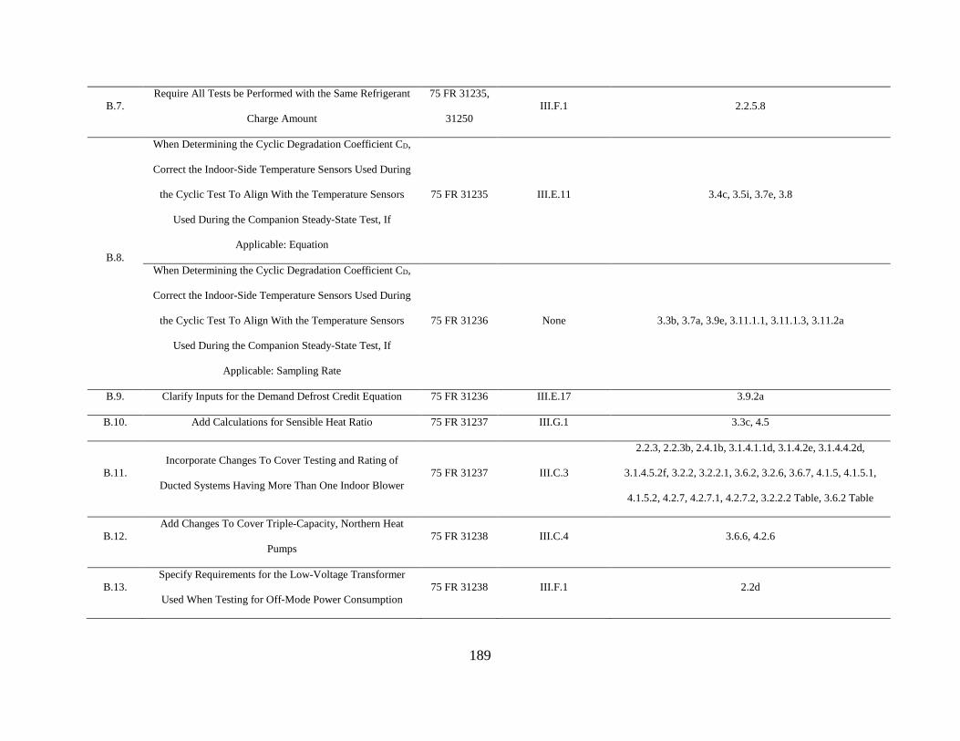
189
B.7. Require All Tests be Performed with the Same Refrigerant
Charge Amount
75 FR 31235,
31250 III.F.1 2.2.5.8
B.8.
When Determining the Cyclic Degradation Coefficient CD,
Correct the Indoor-Side Temperature Sensors Used During
the Cyclic Test To Align With the Temperature Sensors
Used During the Companion Steady-State Test, If
Applicable: Equation
75 FR 31235 III.E.11 3.4c, 3.5i, 3.7e, 3.8
When Determining the Cyclic Degradation Coefficient CD,
Correct the Indoor-Side Temperature Sensors Used During
the Cyclic Test To Align With the Temperature Sensors
Used During the Companion Steady-State Test, If
Applicable: Sampling Rate
75 FR 31236 None 3.3b, 3.7a, 3.9e, 3.11.1.1, 3.11.1.3, 3.11.2a
B.9. Clarify Inputs for the Demand Defrost Credit Equation 75 FR 31236 III.E.17 3.9.2a
B.10. Add Calculations for Sensible Heat Ratio 75 FR 31237 III.G.1 3.3c, 4.5
B.11. Incorporate Changes To Cover Testing and Rating of
Ducted Systems Having More Than One Indoor Blower 75 FR 31237 III.C.3
2.2.3, 2.2.3b, 2.4.1b, 3.1.4.1.1d, 3.1.4.2e, 3.1.4.4.2d,
3.1.4.5.2f, 3.2.2, 3.2.2.1, 3.6.2, 3.2.6, 3.6.7, 4.1.5, 4.1.5.1,
4.1.5.2, 4.2.7, 4.2.7.1, 4.2.7.2, 3.2.2.2 Table, 3.6.2 Table
B.12. Add Changes To Cover Triple-Capacity, Northern Heat
Pumps 75 FR 31238 III.C.4 3.6.6, 4.2.6
B.13. Specify Requirements for the Low-Voltage Transformer
Used When Testing for Off-Mode Power Consumption 75 FR 31238 III.F.1 2.2d

190
B.14. Add Testing Procedures and Calculations for Off Mode
Power Consumption 75 FR 31238 III.D Definitions, 3.13, 4.3
B.17. Update Test Procedure References 75 FR 31243 III.E.12 10 CFR 430.3
Definitions
April 2011 SNOPR
III.A Revise Test Methods and Calculations for Off-Mode Power
and Energy Consumption 76 FR 18107 III.D Definitions, 3.13, 4.3
III.B Revise Requirements for Selecting the Low-Voltage
Transformer Used During Off-Mode Test(s) 76 FR 18109 III.F.1 2.2d
III.D Add Calculation of the Energy Efficiency Ratio for Cooling
Mode Steady-State Tests 76 FR 18111 None 4.7
III.E Revise Off-Mode Performance Ratings 75 FR 31238 III.D Definitions, 3.13, 4.3
October 2011 SNOPR
III.A Reduce Testing Burden and Complexity 76 FR 65618 III.D Definitions, 3.13, 4.3
III.C Add Definition for Shoulder Season 76 FR 65620 III.D Definitions
III.D Revise Test Methods and Calculations for Off-Mode Power
and Energy Consumption 76 FR 65620 III.D Definitions, 3.13, 4.3
III.D.1 Add Provisions for Large Tonnage Systems 76 FR 65621 III.D Definitions, 3.13, 4.3
III.D.2 Add Requirements for Multi-Compressor Systems 76 FR 65622 III.D Definitions, 3.13
November 2015 SNOPR
III.A.1. Basic Model Definition 80 FR 69282 III.A.1 430.2

191
III.A.2. Additional Definitions 80 FR 69284 III.A.2 430.2
III.A.3. Determination of Certified Rating 80 FR 69285 III.A.3 429.16, 1.2
III.A.4. Compliance with Federal (National or Regional) Standards 80 FR 69289 III.A.4 429.16(a)
III.A.5. Certification Reports 80 FR 69290 III.A.5 429.16(c)
III.A.6. Represented Values 80 FR 69291 III.A.6 429.16(a), 430.23
III.A.7. Product-Specific Enforcement Provisions 80 FR 69292 III.A.7 429.134
III.B.1. AEDM General Background 80 FR 69292 III.B.1 429.70(e)
III.B.2. AED< Terminology 80 FR 69292 III.B.2 429.70(e)
III.B.3. Elimination of the ARM Pre-Approval Requirement 80 FR 69293 III.B.3 -
III.B.4. AEDM Validation 80 FR 69294 III.B.4 429.70(e)(2)
III.B.5. AEDM Requirements for Independent Coil Manufacturers 80 FR 69296 III.B.5 429.16
III.B.6. AEDM Verification Testing 80 FR 69296 III.B.6 429.104, 429.70(e)(5)
III.B.7. Failure to Meet Certified Ratings 80 FR 69297 III.B.7 429.70(e)(5)(iv)
III.B.8. Action Following a Determination of Noncompliance 80 FR 69297 III.B.8 429.110, 429.70
III.C.2.
Termination of Waivers Pertaining to Multi-Circuit
Products 80 FR 69299 III.C.2 429.16(a)(1)(ii)(A), 2.4.1b
III.C.3.
Termination of Waiver and Clarification of the Test
Procedure Pertaining to Multi-Blower Products 80 FR 69299 III.C.3 3.1.4.1.1.d, 3.1.4.2.e
III.D.1. Off-Mode Test Temperatures 80 FR 69300 III.D.1 3.13.2.b
III.D.2. Off-Mode Calculation and Weighting of P1 and P2 80 FR 69301 III.D.2 3.13.1, 4.3
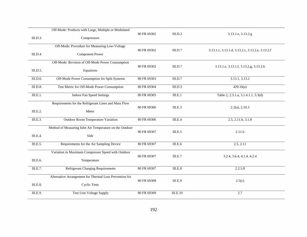
192
III.D.3.
Off-Mode: Products with Large, Multiple or Modulated
Compressors 80 FR 69302 III.D.2 3.13.1.e, 3.13.2.g
III.D.4.
Off-Mode: Procedure for Measuring Low-Voltage
Component Power 80 FR 69302 III.D.7 3.13.1.c, 3.13.1.d, 3.13.2.c, 3.13.2.e, 3.13.2.f
III.D.5.
Off-Mode: Revision of Off-Mode Power Consumption
Equations 80 FR 69302 III.D.7 3.13.1.e, 3.13.1.f, 3.13.2.g, 3.13.2.h
III.D.6. Off-Mode Power Consumption for Split Systems 80 FR 69303 III.D.7 3.13.1, 3.13.2
III.D.8. Test Metric for Off-Mode Power Consumption 80 FR 69304 III.D.3 429.16(a)
III.E.1. Indoor Fan Speed Settings 80 FR 69305 III.E.1 Table 2, 2.3.1.a, 3.1.4.1.1, 3.3(d)
III.E.2.
Requirements for the Refrigerant Lines and Mass Flow
Meter 80 FR 69306 III.E.3 2.2(a), 2.10.3
III.E.3. Outdoor Room Temperature Variation 80 FR 69306 III.E.4 2.5, 2.11.b, 3.1.8
III.E.4.
Method of Measuring Inlet Air Temperature on the Outdoor
Side 80 FR 69307 III.E.5 2.11.b
III.E.5. Requirements for the Air Sampling Device 80 FR 69307 III.E.6 2.5, 2.11
III.E.6.
Variation in Maximum Compressor Speed with Outdoor
Temperature 80 FR 69307 III.E.7 3.2.4, 3.6.4, 4.1.4, 4.2.4
III.E.7. Refrigerant Charging Requirements 80 FR 69307 III.E.8 2.2.5.8
III.E.8.
Alternative Arrangement for Thermal Loss Prevention for
Cyclic Tests 80 FR 69308 III.E.9 2.5(c)
III.E.9. Test Unit Voltage Supply 80 FR 69309 III.E.10 2.7

193
III.E.10. Coefficient of Cyclic Degradation 80 FR 69309 III.E.11 3.2.1, 3.2.2, 3.2.3, 3.2.4, 3.5, 3.6, 3.8
III.E.11. Break-in Periods Prior to Testing 80 FR 69309 III.E.12 3.1.7
III.E.12. Industry Standards that are Incorporated by Reference 80 FR 69310 III.E.13 430.3
III.E.13. Withdrawing References to ASHRAE 116-1995 (RA 2005) 80 FR 69311 III.E.14 -
III.E.14. Additional Changes Based on AHRI 210/240-Draft 80 FR 69311 III.E.15
Table 2, 2.2.5.4.a, 2.2.5.5, 2.3.1.a, 2.4.2, 2.5, 2.11, 3.1.3.1,
3.1.4.1.1, 3.1.5, 3.3(d)
III.E.15. Damping Pressure Transducer Signals 80 FR 69312 III.E.16 2.6(a)
III.F.1. Manufacturer Consultation 80 FR 69313 III.F.1
2.2.5, 2.4.2, 2.2.2, 3.1.4.2(c), 3.1.4.4.2(c), 3.1.4.5(d),
3.5.1(b)(3)
III.F.2. Incorporation by Reference of AHRI 1230-2010
80 FR 69313 III.F.2
1, 3.12, 2.2.a, 2.2.b, 2.2.c, 2.2.1, 2.2.2, 2.2.3(a), 2.2.3(c),
2.2.4, 2.2.5, 2.4 - 2.12, Table 3, section 3.1 (except sections
3.1.3, 3.1.4), 3.3, 3.4, 3.5, 3.7-3.10, 3.13, 4
III.F.3.
Replacement of the Informative Guidance Table for Using
the Federal Test Procedure 80 FR 69314 III.F.3 Table 1
III.F.4. Clarifying the Definition of a Mini-Split System 80 FR 69314 III.F.4 1.2
III.F.5. Clarifying the Definition of a Multi-Split System 80 FR 69315 III.F.5 1.2
* Section numbers in this column refer to the Appendix M test procedure finalized in this notice.

194
G. Additional Comments from Interested Parties
This section discusses additional comments made by interested parties during this
rulemaking that were unrelated to any of DOE’s proposals.
1. Wet Coil Performance
NREL requested DOE require reporting of latent load or amount of water condensation
removal at each test condition to be able to compare equipment performance between dry and
humid regions. NREL also recommend adding two new cooling-mode test conditions to provide
better representation of performance in hot dry regions and three new test cooling-mode
conditions for hot humid regions. (NREL, No. 14 at p. 1)
In the June 2010 NOPR DOE proposed to add a calculation of the sensible heat ratio
(SHR) to its test procedure to provide consumers and their contractors with more information to
allow them to make more informed decisions regarding product selections. 75 FR 31223, 31237
(June 2, 2010). In response, UTC/Carrier and JCI noted in its comments that SHR is currently
provided in manufacturer’s product data. (UTC/Carrier, No. 62 at p. 7; JCI, No. 66 at p. 12). In
this final rule, DOE agrees that SHR was intended to be provided in manufacturer literature and
has not adopted the November 2015 SNOPR proposal to require SHR be reported to DOE (see
Section III.A.5) The latent load and water condensate rate can be calculated based on the SHR in
manufacturers’ product literature and the rated cooling capacity, which should provide sufficient
representation of wet coil performance.
The DOE test procedure requires units to be tested at 80°F dry bulb temperature and 67°F
wet bulb temperature during wet-coil cooling test to represent typical indoor conditions. DOE
does not disagree that the additional test points proposed by NREL would provide additional
representation of performance in hot dry and hot humid regions. However, requiring those

195
additional tests would impose significant test burden on manufacturers. Currently, for a single-
capacity air-conditioner, a manufacturer must conduct four tests and generally conducts in
addition the dry and cyclic tests. Adding five tests would roughly double the test time for these
units. It is not clear how the five additional tests recommended by NREL would improve the
accuracy or field-representativeness of the measurements of SEER or EER. Hence, DOE has
determined not to include these test points in the test procedure.
2. Barometric Pressure Correction
AHRI and JCI proposed that DOE implement a barometric pressure correction
specification for testing. They suggested that barometric pressure be corrected to the altitude
where the mean of the U.S. population lives. (AHRI, No. 70 at p. 13; JCI, No. 66 at p. 11) JCI
suggested addressing barometric pressure by maintaining the enthalpy or humidity ratio of the
entering air, indicating that this has been used effectively for lab correlation. (JCI, No. 66 at p.
11)
DOE has noted the industry’s concern regarding the impact of barometric pressure on the
repeatability of tests and represented values. Currently, there is no systematic data to
demonstrate the effect of barometric pressure on unit performance. However, JCI did not
describe in sufficient detail how the correlation it proposed would work, nor provide data
showing that it properly addresses the barometric pressure issue.
DOE also notes that there has not been a study leading to selection of a standard altitude
or pressure level. DOE is not adopting a barometric pressure correction in this final rule because
an approach for addressing it has not been described in sufficient detail nor shown to provide the
correct adjustment for pressure changes.

196
3. Inlet Screen
DOE proposed in the November 2015 SNOPR the use of a screen downstream of the air
mixer in the outlet of the indoor unit if necessary to improve temperature uniformity. 80 FR at
69278, 69353 (Nov. 9, 2015). Ingersoll Rand commented that inlet and outlet screens on the
indoor unit air stream will impose pressure drop, potentially requiring an increase in the code
tester fan motor size. The code tester is the airflow measuring apparatus as discussed in section
2.6 of Appendix M. They also recommended that regardless of whether the cyclic test is carried
out, the measured performance should be equivalent to the no damper test setup. (Ingersoll Rand,
No. 65 at p. 5-6) DOE notes that the proposal included no requirement for an inlet screen, and
that the screen in the outlet is an option to help meet the temperature uniformity requirements,
but is not required if other means are sufficient to attain uniformity. Further, requirement for
temperature uniformity for the outlet temperature measurement applies whether or not an outlet
damper box is used, i.e. to conduct a cyclic test. DOE has made no changes in response to the
Ingersoll Rand comment.
H. Compliance with other Energy Policy and Conservation Act Requirements
This section discusses and responds to comments related to compliance with Energy
Policy and Conservation Act Requirements.
1. Dates
HARDI commented that given the challenging and complex nature of the test procedure,
the comment period should have been extended by 30 days. HARDI believes that restricting the
comment period to 30-days has a negative impact to smaller companies as they may not have the
means to fully assess the true impact of such a proposal in a narrow time frame. (HARDI, No. 57
at p. 1) JCI requested that the comment period remain open an additional 60 days to finalize their

197
analysis of the proposed test procedure and any resulting clarifying comments. Goodman
commented that the Department has not complied with federal law because it has failed to
provide a 60‐day comment period on this proposed test procedure per 42 USC §6293(b)(2).
(Goodman, No. 73 at p. 22)
DOE notes that it received a request from AHRI to extend the comment period while the
comment period was still open. (AHRI, No. 54, attachment 1). DOE considered the request from
AHRI, but declined to do so. The November 2015 SNOPR represented the third round of
comment on the CAC test procedure rulemaking. DOE is limited by a statutory cap on the
number of days on which it can request public comment, and after three rounds of rulemaking,
DOE is closer to that cap. Consequently, DOE declined the request and did not extend the
comment period for the CAC/HP TP SNOPR. (AHRI, No. 54, Attachment 2)
JCI commented that the raw scope of changes proposed within the SNOPR coupled with the
CAC/HP ECS Working Group and other DOE rulemaking activities is such that a complete and
thorough review, understanding of the proposed changes, and resulting required laboratory changes,
coupled with potential rerating and off mode standby test requirements make complying with the
new test procedure within 180 days of being final particularly challenging if not impossible, and that
the nature of many of the proposed changes to the test procedure require some level of capital
investment and software programming. JCI formally requested that an additional 180 days were
required to fully and completely implement all of the proposed changes in the SNOPR in
addition to the standard 180 days as currently prescribed. (JCI, No. 66 at p. 2-3)
First Co. commented that the 180 day effective date for AEDM compliance proposed by
DOE is unrealistic and suggested an effective date of 18 months from the date the rule is
finalized. (First Co., No. 56 at p. 1)

198
AHRI, ADP, Mortex, and Lennox commented that even with the adoption of the
recommended “Similarity Group” framework, ICMs anticipate that the industry will face
significant challenges to perform all the required testing in the currently required time of 180
days after the publication of the final rule. AHRI formally petitions the Department to extend the
time period to comply to 360 days, as is consistent with its authority. See 42 U.S.C. § 6293(c)(3).
(AHRI, No. 70 at p. 7; ADP, No. 59 at p. 4; Mortex, No. 71 at p. 6-7; Lennox, No. 61 at p. 7)
In response to JCI, DOE notes that this final rule has a reduced scope from that of the
SNOPR. In addition, DOE has made modifications to the off mode test requirement proposals to
reduce test burden, as discussed in section III.D.10. For these reasons, DOE believes that a 180
day time period will be sufficient to implement the finalized test procedure. In response to First
Co., AHRI, ADP, Mortex, and Lennox, DOE notes that 42 U.S.C. § 6293(c)(3) allows individual
manufacturers to petition DOE for additional time to comply. DOE cannot grant this additional
time based on a blanket request from AHRI. However, as discussed in section III.H.2, the
changes adopted in this final rule do not impact measured energy use; and as such, additional test
burden is expected to be limited.
2. Measured Energy Use
EPCA requires that if DOE determines that the amended test procedure would alter the
measured efficiency of a covered product, DOE must amend the applicable energy conservation
standard accordingly. (42 U.S.C. 6293(e)(2)) In the November 2015 SNOPR, DOE determined
that all proposed changes for Appendix M would not alter the measured efficiency of central air
conditioners and heat pumps. DOE proposed all changes that it anticipated might alter the
measured efficiency for Appendix M1, which will be addressed in a separate notice.

199
AHRI, Nortek and UTC/Carrier disagreed that the proposed changes to Appendix M will
not alter the measured efficiency of a covered product. (AHRI, No. 70 at p. 1-2; Nortek, No. 58
at p. 1; UTC/Carrier, No. 62 at p. 23) UTC/Carrier commented that this could be due to CD
testing changing the resultant SEER or HSPF, as it has slightly different stability requirements,
or could be due to manufacturers losing the ability to de-rate and require ratings to be at the
mean of the data/testing results. (UTC/Carrier, No. 62 at p. 23) AHRI contended that the
following proposed changes may impact efficiency: changes to the CD; requirement that
manufacturers rate to the mean of the cooling capacity, heating capacity, and sensible heat ratio
(SHR) and the prohibition on manufacturers’ conservative ratings; requirement that two-speed
products must be tested coil-only, which has the potential to change ratings derived previously
using a blower coil or the alternative rating method; and limit on compressor break-in period.
(AHRI, No. 70 at p. 1-2)
Rheem commented that that each of the changes that have been proposed made a
difference in the rating of a specific equipment sample subject to verification or enforcement
testing and that it is not clear whether the certification rating will increase or decrease for each
proposed change. Rheem commented that it is not clear how the conclusion that proposed
changes do not impact standards was reached. (Rheem, No. 69 at p. 2)
DOE notes that with the exception of compressor break-in period, DOE has made
modifications to its proposals on all the topics for which UTC/Carrier and AHRI expressed
concern over change in represented value. In addition, DOE notes that the current test procedure
does not include a compressor break-in period, and any change in represented value for testing a
specific unit with a break-in period would only serve to improve the value as compared to the

200
standard. For these reasons, DOE confirms that the changes adopted in this final rule do not alter
the measured efficiency of the covered product.
Nortek commented that if the test procedure does not change the efficiency, then all
existing ratings are still valid. (Nortek, No. 58 at p. 1) Similarly, First Co. commented that the
final rule should make clear that ICM test results remain valid until the energy efficiency
standard changes. Retesting is not required merely because the OUM discontinues the outdoor
unit tested by the ICM. (First Co., No. 56 at p. 2) Finally, AHRI, ADP, Mortex, and Lennox
asked for clarity on using data from existing tests to satisfy testing requirements especially
considering the burden associated with outside lab testing. These parties stated that, based on the
proposed framework, ICMs and OUMs would expect that data from existing tests performed to
the current test standard and meeting all other requirements could be used to satisfy the testing
requirement for existing products. In addition, they said that ICMs and OUMs also expect that
tests will remain valid until the energy conservation standard is changed and Appendix M1
becomes effective. (AHRI, No. 70 at p. 7; ADP, No. 59 at p. 4; Mortex, No. 71 at p. 6-7;
Lennox, No. 61 at p. 7)
DOE acknowledges that manufacturers have large amounts of pre-existing data that they
currently use to make representations about and certify the performance of their equipment and
that regenerating all of this data within the 180 day timeframe would be burdensome. As such,
manufacturers may continue to use such data to make representations about the performance of
models after the 180 day timeframe, provided manufacturers are confident that the values are
consistent with those that would be generated under the adopted test procedure.

201
3. Test Burden
EPCA requires that any test procedures prescribed or amended shall be reasonably
designed to produce test results which measure energy efficiency, energy use, or estimated
annual operating cost of a covered product during a representative average use cycle or period of
use, and shall not be unduly burdensome to conduct. (42 U.S.C. 6293(b)(3)) For the reasons
that follow, DOE has concluded that revising the DOE test procedure, per the amendments in
this final rule, to measure the energy consumption of central air conditioners and heat pumps in
active mode and off mode would produce the required test results and would not result in any
undue burden.
As discussed in section IV.B of this final rule, the revised test procedures to determine
the active-mode and standby-mode energy use would require use of the same testing equipment
and facilities that manufacturers are currently using for testing to determine CAC/HP represented
values for certifying performance to DOE. While this notice clarifies the test procedures, and
adopts into regulation the test procedures associated with a number of test procedure waivers,
most of the amendments would not affect test time or the equipment and facilities required to
conduct testing. Possible changes in test burden associated with the amendments of this notice
apply to off mode testing.
The amendments include additional testing to determine off mode energy use, as required
by EPCA. (42 U.S.C. 6295(gg)(2)(A)) This additional testing may require investment in
additional temperature-controlled facilities. However, DOE’s revised test procedure does not
require that every individual combination be tested for off mode, allowing extensive use of
AEDMs in order to reduce test burden.

202
In addition, DOE carefully considered the testing burden on manufacturers in a modified
off mode test procedure that is less burdensome than the proposals it made in the April 2011
SNOPR and October 2011 SNOPR and that addresses stakeholder comment regarding the test
burden of such prior proposals. DOE made further changes to reduce test burden of the off-
mode test procedure in response to comments regarding the November 2015 SNOPR,
specifically (a) allowing the test to be conducted in a temperature-controlled room rather than a
psychrometric test facility, and (b) allowing the test to be conducted without room temperature
control for more designs than allowed by the proposal. Further discussion regarding test burden
associated with the proposals set forth in this notice for determining off mode power
consumption can be found in section III.D.
The November 2015 SNOPR also proposed amendments calling for testing to determine
performance for ICMs. These amendments have been revised in this final rule such that far
fewer models will have to be tested (see the discussion in section III.A.1.d).
DOE allows manufacturers to develop and apply an alternative efficiency determination
method to certify products without the need of testing. In this notice, DOE revises and clarifies
such requirements, as detailed in section III.B, to continue to enable manufacturers who wish to
reduce testing burden to utilize this method.
As detailed in section III.C, manufacturers of certain products covered by test procedure
waivers have already been using the alternative test procedures provided to them for certification
testing. Thus, the inclusion of those alternative test procedures into the test procedure, as revised
in this notice, does not add test burden.
DOE set forth amendments to improve test repeatability, improve the readability and
clarity of the test procedure, and utilize industry procedures that manufacturers may be aware of
203
in an effort to reduce the test burden. Sections III.E, III.F, and III.G present additional detail
regarding such amendments.
DOE carefully considered the impact on testing burden and made efforts to balance
accuracy, repeatability, and test burden during the course of the development of all of the test
procedure amendments. Therefore, DOE determined that the revisions to the central air
conditioner and heat pump test procedure will produce test results that measure energy
consumption during a period of representative use, and that the test procedure will not be unduly
burdensome to conduct.
4. Potential Incorporation of International Electrotechnical Commission Standard 62301 and
International Electrotechnical Commission Standard 62087
Under 42 U.S.C. 6295(gg)(2)(B), EPCA directs DOE to consider IEC Standard 62301
and IEC Standard 62087 when amending test procedures for covered products to include standby
mode and off mode power measurements.
DOE reviewed IEC Standard 62301, “Household electrical appliances – Measurement of
standby power” (Edition 2.0 2011-01),19 and determined that the procedures contained therein
are not sufficient to properly measure off mode power for the unique characteristics of the
components that contribute to off-mode power for CAC/HP products, i.e. the crankcase heaters.
Therefore, DOE determined that referencing IEC Standard 62301 is not appropriate for the
revised test procedure that is the subject of this rulemaking.
DOE reviewed IEC Standard 62087, “Methods of measurement for the power
consumption of audio, video, and related equipment” (Edition 3.0 2011-04), and determined that
19 IEC Standard 62301 covers measurement of power consumption for standby mode and low power modes, as defined therein.

204
it would not be applicable to measuring power consumption of products such as central air
conditioners and heat pumps. Therefore, DOE determined that referencing IEC Standard 62087
is not necessary for the revised test procedure that is the subject of this rulemaking.
IV. Procedural Issues and Regulatory Review
A. Review Under Executive Order 12866
The Office of Management and Budget (OMB) has determined that test procedure
rulemakings do not constitute “significant regulatory actions” under section 3(f) of Executive
Order 12866, Regulatory Planning and Review, 58 FR 51735 (Oct. 4, 1993). Accordingly, this
action was not subject to review under the Executive Order by the Office of Information and
Regulatory Affairs (OIRA) in the Office of Management and Budget.
B. Review Under the Regulatory Flexibility Act
The Regulatory Flexibility Act (5 U.S.C. 601 et seq.) requires preparation of a final
regulatory flexibility analysis (FRFA) for any final rule, unless the agency certifies that the rule,
if promulgated, will not have a significant economic impact on a substantial number of small
entities. As required by Executive Order 13272, “Proper Consideration of Small Entities in
Agency Rulemaking,” 67 FR 53461 (August 16, 2002), DOE published procedures and policies
on February 19, 2003, to ensure that the potential impacts of its rules on small entities are
properly considered during the DOE rulemaking process. 68 FR 7990. DOE has made its
procedures and policies available on the Office of the General Counsel’s website:
http://energy.gov/gc/office-general-counsel.
DOE reviewed today’s final rule under the provisions of the Regulatory Flexibility Act
and the procedures and policies published on February 19, 2003. This final rule prescribes
clarifications to DOE’s already-existing test procedures that will be used to test compliance with

205
energy conservation standards for the products that are the subject of this rulemaking. It also
adds a requirement to conduct testing to determine off mode power consumption. DOE has
estimated the impacts of the test procedure changes on small business manufacturers.
For the purpose of the regulatory flexibility analysis for this rule, DOE adopts the Small
Business Administration (SBA) definition of a small entity within this industry as a
manufacturing enterprise with 1,250 employees or fewer. DOE used the small business size
standards published by the SBA to determine whether any small entities would be required to
comply with the rule. The size standards are codified at 13 CFR Part 121. The standards are
listed by North American Industry Classification System (NAICS) code and industry description
and are available at https://www.sba.gov/sites/default/files/files/Size_Standards_Table.pdf.
Central air conditioner and heat pump manufacturing is classified under NAICS 333415,
“Air-Conditioning and Warm Air Heating Equipment and Commercial and Industrial
Refrigeration Equipment Manufacturing.” 70 FR 12395 (March 11, 2005). DOE reviewed
AHRI’s listing of central air conditioner and heat pump product manufacturer members and
surveyed the industry to develop a list of domestic manufacturers. As a result of this review,
DOE identified 24 domestic small manufacturers of central air conditioners and heat pumps.
Potential impacts of the amended test procedure on all manufacturers, including small
businesses, come from impacts associated with the cost of proposed additional testing. In the
June 2010 NOPR, DOE estimated the incremental cost of the proposed additional tests described
in 10 CFR Part 430, Subpart B, Appendix M (proposed section 3.13) to be an increase of $1,000
to $1,500 per unit tested, indicating that the largest additional cost would be associated with
conducting steady-state cooling mode tests and the dry climate tests for the SEER-HD rating).
75 FR 31243 (June 2, 2010). DOE has eliminated tests associated with SEER-HD from this
206
rulemaking. DOE conservatively estimates that off mode testing might cost $1,000 (roughly
one-fifth of the $5000 cost of active mode testing—see 75 FR 31243 (June 2, 2010)). Assuming
two off mode tests per tested model, this is an average test cost of $2,000 per model. This
estimate does not take into consideration the possibility of the use of AEDMs for establishing
off-mode represented values, which could significantly reduce the off-mode testing burden. It
also does not take into account the changes in off-mode testing adopted in this final rule to
reduce test burden, i.e. specifically allowing more units to test off-mode energy use in a room
without temperature control, and clarifying that off-mode testing does not need to be conducted
in a psychrometric chamber (see section III.D for details).
The off mode test procedure primarily measures energy use of outdoor units. The off-
mode power input represented values for CAC/HP model combinations including indoor units
manufactured by ICMs would be equal to the off-mode represented values of other combinations
using the same outdoor units. Hence, it is expected that small-business ICM manufacturers
would use these same represented values rather than retesting the outdoor units and thus not be
affected by the off-mode testing required by this rule. Because the incremental cost of running
the extra off mode tests is the same for all other manufacturers, DOE believes that they would
incur comparable costs for testing to certify off mode power use for basic models as a result of
this final test procedure.
With respect to the provisions addressing AEDMs, the amendments contained herein will
not increase the testing or reporting burden of OUMs who currently use, or are eligible to use, an
AEDM to certify their products. The amendments eliminate the ARM nomenclature and treat
these methods as AEDMs, eliminate the pre-approval requirement for product AEDMs, revise
the requirements for validation of an AEDM in a way that would not require more testing than

207
that required by the AEDM provisions included in the March 7, 2011 Certification, Compliance
and Enforcement Final Rule (76 FR 12422) (“March 2011 Final Rule”), and amend the process
that DOE promulgated in the March 2011 Final Rule for validating AEDMs and verifying
certifications based on the use of AEDMs. Because these AEDM-related amendments will either
have no effect on test burden or decrease burden related to testing and determination of
represented values of products (e.g., elimination of ARM pre-approval), DOE has determined
these amendments will result in no significant change in testing or reporting burden.
To evaluate the potential cost impact of off-mode testing for small OUMs, DOE
estimated small manufacturers’ total cost of testing. As discussed above, DOE identified 24
domestic small business manufacturers of CAC/HP products. Of these, only OUMs that operate
their own manufacturing facilities (i.e., are not private labelers selling only products
manufactured by other entities) and OUM importing private labelers would be subject to the
additional requirements for testing required by this rule. DOE identified 12 such manufacturers,
but was able to estimate the number of basic models associated only with nine of these. DOE
calculated the additional testing expense for these nine domestic small businesses. Assuming the
$2,000 estimate of additional test cost per basic model, and that testing of basic models may not
have to be updated more than once every five years, DOE estimated that the annual cost impact
of the additional testing is $400 per basic model when the cost is spread over five years.
DOE currently requires that only one combination associated with any given outdoor unit
be laboratory tested. 10 CFR 430.24(m). The majority of central air conditioners and heat
pumps offered by a manufacturer are typically split systems that are not required to be laboratory
tested but can be certified using an AEDM that does not require DOE testing of these units.
DOE reviewed available data for the nine small businesses to estimate the incremental testing

208
cost burden those firms might experience due to the revised test procedure. These manufacturers
had an average of 35 models requiring testing. DOE determined the numbers of models using
DOE’s Compliance Certification Database (https://www.regulations.doe.gov/certification-data/).
The additional testing cost for final certification for 35 models was estimated at $70,000.
Meanwhile, these certifications would be expected to last the product life, estimated to be at least
five years. This test burden is therefore estimated to be approximately $14,000 annually.
In addition to off-mode testing costs facing small OUMs of central air conditioners and
heat pumps, this final rule will require ICMs to conduct testing for their basic models. However,
DOE has modified its definition of basic model for ICM to match the Similarity Group concept
suggested by several stakeholders (see section III.A.1.d). Further, DOE has relaxed its
requirement for testing of ICM heat pump combinations, such that only a limited number of heat
pump basic models would require testing, i.e. those for which a test has not been conducted for
an equivalent air-conditioner model. DOE identified three domestic small ICMs subject to
testing costs under this final rule.
To calculate the additional testing costs facing small ICMs, DOE used data provided by
AHRI regarding what they referred to as Similarity Groups and which DOE is considering to be
basic models. Specifically, DOE assumed an average of 42 basic models per ICM based on the
AHRI data. (AHRI, No. 70 at p. 6) DOE also assumed $7,500 in added costs per test and two
tests per basic model. (AHRI, No. 70 at p. 4) Assuming $15,000 in additional testing costs per
basic model (to cover two tests per model), and that testing of basic models may not have to be
updated more than once every five years, DOE estimated that the total additional testing cost for
final certification of 42 basic models for each small ICM would amount to costs averaging
$126,000 per year.
209
DOE will provide its certification and final supporting statement of factual basis to the
Chief Counsel for Advocacy of the SBA for review under 5 U.S.C. 605(b).
C. Review Under the Paperwork Reduction Act of 1995
Manufacturers of central air conditioners and heat pumps must certify to DOE that their
products comply with any applicable energy conservation standards. In certifying compliance,
manufacturers must test their products according to the DOE test procedures for central air
conditioners and heat pumps, including any amendments adopted for those test procedures.
DOE has established regulations for the certification and recordkeeping requirements for all
covered consumer products and commercial equipment, including central air conditioners and
heat pumps. 76 FR 12422 (March 7, 2011); 80 FR 5099 (Jan. 30, 2015). The collection-of-
information requirement for the certification and recordkeeping is subject to review and approval
by OMB under the Paperwork Reduction Act (PRA). This requirement has been approved by
OMB under OMB control number 1910-1400. Public reporting burden for the certification is
estimated to average 30 hours per response, including the time for reviewing instructions,
searching existing data sources, gathering and maintaining the data needed, and completing and
reviewing the collection of information.
Notwithstanding any other provision of the law, no person is required to respond to, nor
shall any person be subject to a penalty for failure to comply with, a collection of information
subject to the requirements of the PRA, unless that collection of information displays a currently
valid OMB Control Number.
D. Review Under the National Environmental Policy Act of 1969
In this final rule, DOE amends its test procedure for central air conditioners and heat
pumps. DOE has determined that this final rule falls into a class of actions that are categorically
210
excluded from review under the National Environmental Policy Act of 1969 (42 U.S.C. 4321 et
seq.) and DOE’s implementing regulations at 10 CFR Part 1021. Specifically, this rule amends
the existing test procedures without affecting the amount, quality or distribution of energy usage,
and, therefore, would not result in any environmental impacts. Thus, this rulemaking is covered
by Categorical Exclusion A5 under 10 CFR Part 1021, Subpart D, which applies to any
rulemaking that interprets or amends an existing rule without changing the environmental effect
of that rule. Accordingly, neither an environmental assessment nor an environmental impact
statement is required.
DOE’s CX determination for this rule is available at http://energy.gov/nepa/categorical-
exclusion-cx-determinations-cx
E. Review Under Executive Order 13132
Executive Order 13132, “Federalism,” 64 FR 43255 (August 4, 1999) imposes certain
requirements on agencies formulating and implementing policies or regulations that preempt
State law or that have Federalism implications. The Executive Order requires agencies to
examine the constitutional and statutory authority supporting any action that would limit the
policymaking discretion of the States and to carefully assess the necessity for such actions. The
Executive Order also requires agencies to have an accountable process to ensure meaningful and
timely input by State and local officials in the development of regulatory policies that have
Federalism implications. On March 14, 2000, DOE published a statement of policy describing
the intergovernmental consultation process it will follow in the development of such regulations.
65 FR 13735. DOE has examined this final rule and has determined that it would not have a
substantial direct effect on the States, on the relationship between the national government and
the States, or on the distribution of power and responsibilities among the various levels of

211
government. EPCA governs and prescribes Federal preemption of State regulations as to energy
conservation for the products that are the subject of this rule. States can petition DOE for
exemption from such preemption to the extent, and based on criteria, set forth in EPCA. (42
U.S.C. 6297(d)) No further action is required by Executive Order 13132.
F. Review Under Executive Order 12988
Regarding the review of existing regulations and the promulgation of new regulations,
section 3(a) of Executive Order 12988, “Civil Justice Reform,” 61 FR 4729 (Feb. 7, 1996),
imposes on Federal agencies the general duty to adhere to the following requirements: (1)
eliminate drafting errors and ambiguity; (2) write regulations to minimize litigation; (3) provide
a clear legal standard for affected conduct rather than a general standard; and (4) promote
simplification and burden reduction. Section 3(b) of Executive Order 12988 specifically requires
that Executive agencies make every reasonable effort to ensure that the regulation: (1) clearly
specifies the preemptive effect, if any; (2) clearly specifies any effect on existing Federal law or
regulation; (3) provides a clear legal standard for affected conduct while promoting
simplification and burden reduction; (4) specifies the retroactive effect, if any; (5) adequately
defines key terms; and (6) addresses other important issues affecting clarity and general
draftsmanship under any guidelines issued by the Attorney General. Section 3(c) of Executive
Order 12988 requires Executive agencies to review regulations in light of applicable standards in
sections 3(a) and 3(b) to determine whether they are met or it is unreasonable to meet one or
more of them. DOE has completed the required review and determined that, to the extent
permitted by law, the rule meets the relevant standards of Executive Order 12988.
212
G. Review Under the Unfunded Mandates Reform Act of 1995
Title II of the Unfunded Mandates Reform Act of 1995 (UMRA) requires each Federal
agency to assess the effects of Federal regulatory actions on State, local, and Tribal governments
and the private sector. Pub. L. No. 104-4, sec. 201 (codified at 2 U.S.C. 1531). For a regulatory
action likely to result in a rule that may cause the expenditure by State, local, and Tribal
governments, in the aggregate, or by the private sector of $100 million or more in any one year
(adjusted annually for inflation), section 202 of UMRA requires a Federal agency to publish a
written statement that estimates the resulting costs, benefits, and other effects on the national
economy. (2 U.S.C. 1532(a), (b)) The UMRA also requires a Federal agency to develop an
effective process to permit timely input by elected officers of State, local, and Tribal
governments on a proposed “significant intergovernmental mandate,” and requires an agency
plan for giving notice and opportunity for timely input to potentially affected small governments
before establishing any requirements that might significantly or uniquely affect small
governments. On March 18, 1997, DOE published a statement of policy on its process for
intergovernmental consultation under UMRA. 62 FR 12820; also available at
http://energy.gov/gc/office-general-counsel. DOE examined this final rule according to UMRA
and its statement of policy and determined that the rule contains neither an intergovernmental
mandate, nor a mandate that may result in the expenditure of $100 million or more in any year,
so these requirements do not apply.
H. Review Under the Treasury and General Government Appropriations Act, 1999
Section 654 of the Treasury and General Government Appropriations Act, 1999 (Pub. L.
105-277) requires Federal agencies to issue a Family Policymaking Assessment for any rule that
may affect family well-being. This final rule will not have any impact on the autonomy or

213
integrity of the family as an institution. Accordingly, DOE has concluded that it is not necessary
to prepare a Family Policymaking Assessment.
I. Review Under Executive Order 12630
DOE has determined, under Executive Order 12630, “Governmental Actions and
Interference with Constitutionally Protected Property Rights” 53 FR 8859 (March 18, 1988), that
this regulation will not result in any takings that might require compensation under the Fifth
Amendment to the U.S. Constitution.
J. Review Under the Treasury and General Government Appropriations Act, 2001
Section 515 of the Treasury and General Government Appropriations Act, 2001 (44
U.S.C. 3516 note) provides for agencies to review most disseminations of information to the
public under guidelines established by each agency pursuant to general guidelines issued by
OMB. OMB’s guidelines were published at 67 FR 8452 (Feb. 22, 2002), and DOE’s guidelines
were published at 67 FR 62446 (Oct. 7, 2002). DOE has reviewed this final rule under the OMB
and DOE guidelines and has concluded that it is consistent with applicable policies in those
guidelines.
K. Review Under Executive Order 13211
Executive Order 13211, “Actions Concerning Regulations That Significantly Affect
Energy Supply, Distribution, or Use,” 66 FR 28355 (May 22, 2001), requires Federal agencies to
prepare and submit to OMB, a Statement of Energy Effects for any significant energy action. A
“significant energy action” is defined as any action by an agency that promulgated or is expected
to lead to promulgation of a final rule, and that: (1) is a significant regulatory action under
Executive Order 12866, or any successor order; and (2) is likely to have a significant adverse
effect on the supply, distribution, or use of energy; or (3) is designated by the Administrator of
214
OIRA as a significant energy action. For any significant energy action, the agency must give a
detailed statement of any adverse effects on energy supply, distribution, or use associated with
the rule’s implementation, and of reasonable alternatives to the action and their expected benefits
on energy supply, distribution, and use.
The regulatory action is not a significant regulatory action under Executive Order 12866.
Moreover, it will not have a significant adverse effect on the supply, distribution, or use of
energy, nor has it been designated as a significant energy action by the Administrator of OIRA.
Therefore, it is not a significant energy action, and, accordingly, DOE has not prepared a
Statement of Energy Effects.
L. Review Under Section 32 of the Federal Energy Administration Act of 1974
Under section 301 of the Department of Energy Organization Act (Pub. L. 95–91; 42
U.S.C. 7101), DOE must comply with section 32 of the Federal Energy Administration Act of
1974, as amended by the Federal Energy Administration Authorization Act of 1977. (15 U.S.C.
788; FEAA) Section 32 essentially provides in relevant part that, where a proposed rule
authorizes or requires use of commercial standards, the notice of proposed rulemaking must
inform the public of the use and background of such standards. In addition, section 32(c)
requires DOE to consult with the Attorney General and the Chairman of the Federal Trade
Commission (FTC) concerning the impact of the commercial or industry standards on
competition.
The rule incorporates testing methods contained in the following commercial standards:
AHRI 210/240-2008, Performance Rating of Unitary Air-Conditioning & Air-Source Heat Pump
Equipment; and AHRI 1230-2010, Performance Rating of Variable Refrigerant Flow Multi-Split
Air-Conditioning and Heat Pump Equipment. While the amended test procedure is not

215
exclusively based on AHRI 210/240-2008 or AHRI 1230-2010, one component of the test
procedure, namely test setup requirements, adopts language from AHRI 210/240-2008 without
amendment; and another component of the test procedure, namely test setup and test
performance requirements for multi-split systems, adopts language from AHRI 1230-2010
without amendment. DOE has evaluated these standards and consulted with the Attorney
General and the Chairman of the FTC and has concluded that this final rule fully complies with
the requirements of section 32(b) of the FEAA.
M. Congressional Notification
As required by 5 U.S.C. 801, DOE will report to Congress on the promulgation of this
rule before its effective date. The report will state that it has been determined that the rule is not a
"major rule" as defined by 5 U.S.C. 804(2).
N. Description of Materials Incorporated by Reference
In this final rule, DOE is incorporating by reference specific sections, figures, and tables
in the following two test standards published by AHRI: ANSI/AHRI 210/240-2008 with
Addenda 1 and 2, titled “Performance Rating of Unitary Air-Conditioning & Air-Source Heat
Pump Equipment;” and ANSI/AHRI 1230-2010 with Addendum 2, titled “Performance Rating
of Variable Refrigerant Flow (VRF) Multi-Split Air-Conditioning and Heat Pump Equipment.”
DOE is also updating its incorporation by reference (IBR) to the most recent versions of specific
standards, figures, and tables in the following standards published by ASHRAE: ASHRAE 23.1-
2010 titled “Methods of Testing for Rating the Performance of Positive Displacement
Refrigerant Compressors and Condensing Units that Operate at Subcritical Temperatures of the
Refrigerant”, ANSI/ASHRAE 37-2009, Methods of Testing for Rating Electrically Driven

216
Unitary Air-Conditioning and Heat Pump Equipment, ANSI/ASHRAE 41.1-2013 titled
“Standard Method for Temperature Measurement”, ASHRAE 41.6-2014 titled “Standard
Method for Humidity Measurement”, and ASHRAE 41.9-2011 titled “Standard Methods for
Volatile-Refrigerant Mass Flow Measurements Using Calorimeters”. Finally, DOE is updating
its IBR to specific figures in the most recent version of the following test procedure from
ASHRAE and AMCA: ANSI/AMCA 210-2007, ANSI/ASHRAE 51-2007, Laboratory Methods
of Testing Fans for Certified Aerodynamic Performance Rating.
AHRI 210/240-2008 is an industry accepted test procedure that measures the cooling and
heating performance of central air conditioners and heat pumps and is applicable to products sold
in North America. The test procedure in this final rule references various sections of AHRI
210/240-2008 that address test setup, test conditions, and rating requirements. AHRI 210/240-
2008 is readily available on AHRI’s website at
http://www.ahrinet.org/site/686/Standards/HVACR-Industry-Standards/Search-Standards.
AHRI 1230-2010 is an industry accepted test procedure that measures the cooling and
heating performance of variable refrigerant flow (VRF) multi-split air conditioners and heat
pumps and is applicable to products sold in North America. The test procedure in this final rule
for VRF multi-split systems references various sections of AHRI 1230-2010 that address test
setup, test conditions, and rating requirements. AHRI 1230-2010 is readily available on AHRI’s
website at http://www.ahrinet.org/site/686/Standards/HVACR-Industry-Standards/Search-
Standards.
ASHRAE 23.1-2010 is an industry accepted test procedure for rating the thermodynamic
performance of positive displacement refrigerant compressors and condensing units that operate
at subcritical temperatures. The test procedure in this final rule references sections of ASHRAE

217
23.1-2010 that address requirements, instruments, methods of testing, and testing procedure
specific to compressor calibration. ASHRAE 23.1-2010 can be purchased from ASHRAE’s
website at https://www.ashrae.org/resources--publications.
ANSI/ASHRAE 37-2009 is an industry accepted standard that provides test methods for
determining the cooling capacity of unitary air-conditioning equipment and the cooling or
heating capacities, or both, of unitary heat pump equipment. The test procedure in this final rule
references various sections of ANSI/ASHRAE 37-2009 that address test conditions and test
procedures, updating the IBR from a previous version of this standard, ASHRAE 37-2005.
ANSI/ASHRAE 37-2009 can be purchased from ASHRAE’s website at
https://www.ashrae.org/resources--publications.
ANSI/ASHRAE 41.1-2013 is an industry accepted method for measuring temperature in
testing heating, refrigerating, and air-conditioning equipment. The test procedure in this final
rule references sections of ANSI/ASHRAE 41.1-2013 that address requirements, instruments,
and methods for measuring temperature. ANSI/ASHRAE 41.1-2013 can be purchased from
ASHRAE’s website at https://www.ashrae.org/resources--publications.
ASHRAE 41.2-1987 (RA 1992) is an industry accepted test method for measuring
airflow. The test procedure in this final rule references sections of ASHRAE 41.2-1987 (RA
1992) that address test setup and test methods. ASHRAE 41.2-1987 (RA 1992) can be
purchased from ASHRAE’s website at https://www.ashrae.org/resources--publications.
ASHRAE 41.6-2014 is an industry accepted test method for measuring humidity of moist
air. The test procedure in this final rule references sections of ASHRAE 41.6-2014 that address
requirements, instruments, and methods for measuring humidity. ASHRAE 41.6-2014 can be
purchased from ASHRAE’s website at https://www.ashrae.org/resources--publications.
218
ASHRAE 41.9-2011 is an industry accepted standard that provides recommended
practices for measuring the mass flow rate of volatile refrigerants using calorimeters. The test
procedure in this final rule references sections of ASHRAE 41.9-2011 that address requirements,
instruments, and methods for measuring refrigerant flow during compressor calibration.
ASHRAE 41.9-2011 can be purchased from ASHRAE’s website at
https://www.ashrae.org/resources--publications.
ANSI/ASHRAE Standard 116-2010 is an industry accepted standard that provides test
methods and calculation procedures for determining the capacities and cooling seasonal
efficiency ratios for unitary air-conditioning, and heat pump equipment and heating seasonal
performance factors for heat pump equipment. The test procedure in this final rule references
various sections of ANSI/ASHRAE 116-2010 that addresses test methods and calculations,
updating the IBR from a previous version of the standard, ASHRAE 116-1995 (RA 2005).
ANSI/ASHRAE Standard 116-2010 can be purchased from ASHRAE’s website at
https://www.ashrae.org/resources--publications.
AMCA 210-2007 is an industry accepted standard that establishes uniform test methods
for a laboratory test of a fan or other air moving device to determine its aerodynamic
performance in terms of air flow rate, pressure developed, power consumption, air density, speed
of rotation, and efficiency for rating or guarantee purposes. The test procedure in this final rule
references various sections of AMCA 210-2007 that address test conditions, updating the IBR
from a previous version of this standard, ASHRAE/AMCA 51-1999/210-1999. AMCA 210-2007
can be purchased from AMCA’s website at http://www.amca.org/store/index.php.

220
For the reasons set forth in the preamble, DOE amends parts 429 and 430 of chapter II of title
10, subpart B, Code of Federal Regulations, to read as follows:
PART 429– CERTIFICATION, COMPLIANCE, AND ENFORCEMENT FOR
CONSUMER PRODUCTS AND COMMERCIAL AND INDUSTRIAL EQUIPMENT
1. The authority citation for part 429 continues to read as follows:
Authority: 42 U.S.C. 6291–6317.
2. Section 429.12 is amended by revising paragraphs (b)(8) and (12) to read as follows:
§ 429.12 General requirements applicable to certification reports.
* * * * *
(b) * * *
(8) The test sample size (i.e., number of units tested for the basic model, or in the case of
single-split system or single-package central air conditioners and central air conditioning heat
pumps, or multi-split, multi-circuit, or multi-head mini-split systems other than the “tested
combination,” for each individual combination or individual model). Enter “0” if an AEDM was
used in lieu of testing (and in the case of central air conditioners and central air conditioning heat
pumps, this must be indicated separately for each metric);
* * * * *
(12) If the test sample size is listed as “0” to indicate the certification is based upon the use of
an alternate way of determining measures of energy conservation, identify the method used for
determining measures of energy conservation (such as “AEDM,” or linear interpolation).
Manufacturers of commercial packaged boilers, commercial water heating equipment,
commercial refrigeration equipment, commercial HVAC equipment, and central air conditioners

221
and central air conditioning heat pumps must provide the manufacturer's designation (name or
other identifier) of the AEDM used; and
* * * * *
3. Section 429.16 is revised to read as follows:
Ҥ 429.16 Central air conditioners and central air conditioning heat pumps.
(a) Determination of Represented Value--(1) Required represented values. Determine the
represented values (including SEER, EER, HSPF, PW,OFF, cooling capacity, and heating capacity,
as applicable) for the individual models/combinations (or “tested combinations”) specified in the
following table.
Category Equipment Subcategory Required Represented Values
Single-Package Unit
Single-Package AC (including Space-Constrained) Every individual model distributed in commerce. Single-Package HP (including Space-Constrained)
Outdoor Unit and Indoor Unit (Distributed in Commerce by OUM)
Single-Split System AC with Single-Stage or Two-Stage Compressor (including Space-Constrained and Small-Duct, High Velocity Systems (SDHV))
Every individual combination distributed in commerce, including all coil-only and blower coil combinations. For each model of outdoor unit, this must include at least one coil-only value that is representative of the least efficient combination distributed in commerce with the particular model of outdoor unit.
Single-Split System AC with Other Than Single-Stage or Two-Stage Compressor (including Space-Constrained and SDHV)
Every individual combination distributed in commerce, including all coil-only and blower coil combinations.
Single-Split-System HP (including Space-Constrained and SDHV)
Every individual combination distributed in commerce.
Multi-Split, Multi-Circuit, or Multi-Head Mini-Split Split System – non-SDHV
For each model of outdoor unit, at a minimum, a non-ducted “tested combination.” For any model of outdoor unit also sold with models of ducted indoor units, a ducted “tested combination.” Additional representations are allowed, as described in paragraph (c)(3)(i) of this section.
Multi-Split, Multi-Circuit, or Multi-Head Mini-Split Split System – SDHV
For each model of outdoor unit, an SDHV “tested combination.” Additional representations are allowed, as described in paragraph (c)(3)(ii) of this section.

222
Indoor Unit Only Distributed in Commerce by ICM)
Single-Split-System Air Conditioner (including Space-Constrained and SDHV) Every individual combination distributed in
commerce. Single-Split-System Heat Pump (including Space-Constrained and SDHV)
Multi-Split, Multi-Circuit, or Multi-Head Mini-Split Split System – SDHV
For a model of indoor unit within each basic model, an SDHV “tested combination.” Additional representations are allowed, as described in section (c)(3)(ii).
Outdoor Unit with no Match Every model of outdoor unit distributed in commerce (tested with a model of coil-only indoor unit as specified in paragraph (c)(2) of this section).
(2) PW,OFF. If individual models of single-package systems or individual combinations (or
“tested combinations”) of split systems that are otherwise identical are offered with multiple
options for off mode-related components, determine the represented value for the individual
model/combination with the crankcase heater and controls that are the most consumptive. A
manufacturer may also determine represented values for individual models/combinations with
less consumptive off mode options; however, all such options must be identified with different
model numbers for single-package systems or for outdoor units (in the case of split systems).
(3) Limitations for represented values of individual combinations. The following paragraphs
explains the limitations for represented values of individual combinations (or “tested
combinations”).
(A) Regional. A basic model may only be certified as compliant with a regional standard
if all individual combinations within that basic model meet the regional standard for which it is
certified. If a model of outdoor unit is certified below a regional standard, then the model of
outdoor unit must have a unique model number for distribution in each region. An ICM cannot
certify a basic model containing a representative value that is more efficient than any
combination certified by an OUM containing the same outdoor unit.
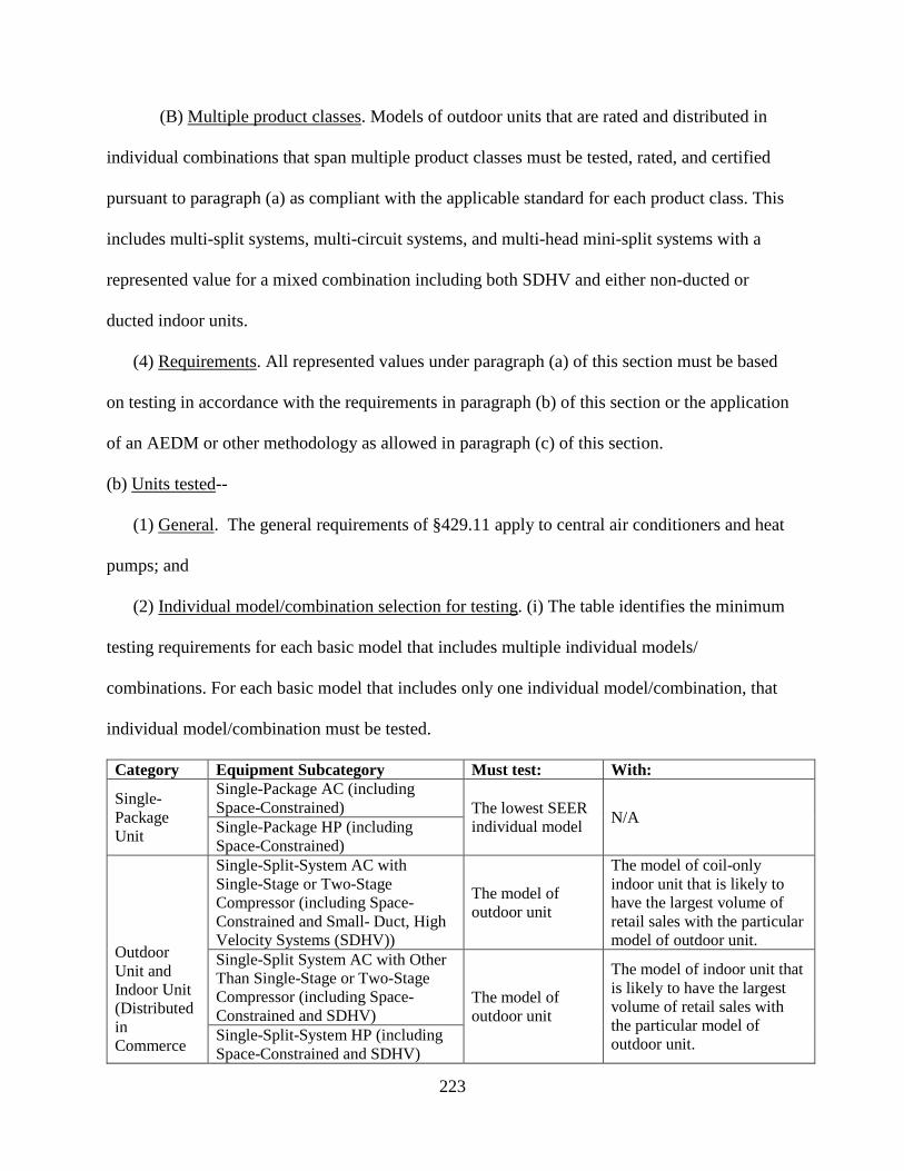
223
(B) Multiple product classes. Models of outdoor units that are rated and distributed in
individual combinations that span multiple product classes must be tested, rated, and certified
pursuant to paragraph (a) as compliant with the applicable standard for each product class. This
includes multi-split systems, multi-circuit systems, and multi-head mini-split systems with a
represented value for a mixed combination including both SDHV and either non-ducted or
ducted indoor units.
(4) Requirements. All represented values under paragraph (a) of this section must be based
on testing in accordance with the requirements in paragraph (b) of this section or the application
of an AEDM or other methodology as allowed in paragraph (c) of this section.
(b) Units tested--
(1) General. The general requirements of §429.11 apply to central air conditioners and heat
pumps; and
(2) Individual model/combination selection for testing. (i) The table identifies the minimum
testing requirements for each basic model that includes multiple individual models/
combinations. For each basic model that includes only one individual model/combination, that
individual model/combination must be tested.
Category Equipment Subcategory Must test: With:
Single-Package Unit
Single-Package AC (including Space-Constrained) The lowest SEER
individual model N/A Single-Package HP (including Space-Constrained)
Outdoor Unit and Indoor Unit (Distributed in Commerce
Single-Split-System AC with Single-Stage or Two-Stage Compressor (including Space-Constrained and Small- Duct, High Velocity Systems (SDHV))
The model of outdoor unit
The model of coil-only indoor unit that is likely to have the largest volume of retail sales with the particular model of outdoor unit.
Single-Split System AC with Other Than Single-Stage or Two-Stage Compressor (including Space-Constrained and SDHV)
The model of outdoor unit
The model of indoor unit that is likely to have the largest volume of retail sales with the particular model of outdoor unit. Single-Split-System HP (including
Space-Constrained and SDHV)

224
by OUM)
Multi-Split, Multi-Circuit, or Multi-Head Mini-Split Split System – non-SDHV
The model of outdoor unit
At a minimum, a “tested combination” composed entirely of non-ducted indoor units. For any models of outdoor units also sold with models of ducted indoor units, a second “tested combination” composed entirely of ducted indoor units must be tested (in addition to the non-ducted combination).
Multi-Split, Multi-Circuit, or Multi-Head Mini-Split Split System – SDHV
The model of outdoor unit
A “tested combination” composed entirely of SDHV indoor units.
Indoor Unit Only (Distributed in Commerce by ICM)
Single-Split-System Air Conditioner (including Space-Constrained and SDHV)
A model of indoor unit The least efficient model of
outdoor unit with which it will be paired where the least efficient model of outdoor unit is the model of outdoor unit in the lowest SEER combination as certified by the OUM. If there are multiple models of outdoor unit with the same lowest SEER represented value, the ICM may select one for testing purposes.
Single-Split-System Heat Pump (including Space-Constrained and SDHV)
Nothing, as long as an equivalent air conditioner basic model has been tested.
If an equivalent air conditioner basic model has not been tested, must test a model of indoor unit
Multi-Split, Multi-Circuit, or Multi-Head Mini-Split Split System – SDHV
A model of indoor unit
A “tested combination” composed entirely of SDHV indoor units, where the outdoor unit is the least efficient model of outdoor unit with which the SDHV indoor unit will be paired. The least efficient model of outdoor unit is the model of outdoor unit in the lowest SEER combination as certified by the OUM. If there are multiple models of outdoor unit with the same lowest SEER represented value, the ICM may select one for testing purposes.

225
Outdoor Unit with No Match The model of outdoor unit
A model of coil-only indoor unit meeting the requirements of section 2.2e of Appendix M to subpart B of part 430.
(ii) Each individual model/combination (or “tested combination”) identified in paragraph
(b)(2)(i) of this section is not required to be tested for PW,OFF. Instead, at a minimum, among
individual models/combinations with similar off-mode construction (even spanning different
models of outdoor units), a manufacturer must test at least one individual model/combination for
PW,OFF.
(3) Sampling plans and representative values. (i) For individual models (for single-package
systems) or individual combinations (for split–systems, including “tested combinations” for
multi-split, multi-circuit, and multi-head mini-split systems) with represented values determined
through testing, each individual model/combination (or “tested combination”) must have a
sample of sufficient size tested in accordance with the applicable provisions of this subpart. For
heat pumps (other than heating-only heat pumps), all units of the sample population must be
tested in both the cooling and heating modes and the results used for determining all
representations. The represented values for any individual model/combination must be assigned
such that:
(A) Off-Mode. Any represented value of power consumption or other measure of
energy consumption for which consumers would favor lower values must be greater than or
equal to the higher of:
(1) The mean of the sample, where:
�̅�𝑥 =1𝑛𝑛�𝑥𝑥𝑖𝑖
𝑛𝑛
𝑖𝑖=1
and, �̅�𝑥 is the sample mean; n is the number of samples; and xi is the ith sample; Or,

226
(2) The upper 90 percent confidence limit (UCL) of the true mean divided by
1.05, where:
𝑈𝑈𝑈𝑈𝑈𝑈 = �̅�𝑥 + 𝑡𝑡.90(𝑠𝑠√𝑛𝑛
)
And �̅�𝑥 is the sample mean; s is the sample standard deviation; n is the number of samples; and
t0.90 is the t statistic for a 90 percent one-tailed confidence interval with n-1 degrees of freedom
(from appendix D). Round represented values of off-mode power consumption to the nearest
watt.
(B) SEER, EER, and HSPF. Any represented value of the energy efficiency or other
measure of energy consumption for which consumers would favor higher values shall be less
than or equal to the lower of:
(1) The mean of the sample, where:
�̅�𝑥 =1𝑛𝑛�𝑥𝑥𝑖𝑖
𝑛𝑛
𝑖𝑖=1
and, �̅�𝑥 is the sample mean; n is the number of samples; and xi is the ith sample; or,
(2) The lower 90 percent confidence limit (LCL) of the true mean divided by
0.95, where:
𝑈𝑈𝑈𝑈𝑈𝑈 = �̅�𝑥 − 𝑡𝑡.90(𝑠𝑠√𝑛𝑛
)
And �̅�𝑥 is the sample mean; s is the sample standard deviation; n is the number of samples; and
t0.90 is the t statistic for a 90 percent one-tailed confidence interval with n-1 degrees of freedom
(from Appendix D). Round represented values of EER, SEER, and HSPF to the nearest 0.05.

227
(C) Cooling Capacity. The represented value of cooling capacity must be a self-
declared value that is no less than 95 percent of the mean of the cooling capacities measured for
the units in the sample, rounded:
(1) To the nearest 100 Btu/h if cooling capacity is less than 20,000 Btu/h,
(2) To the nearest 200 Btu/h if cooling capacity is greater than or equal to 20,000
Btu/h but less than 38,000 Btu/h, and
(3) To the nearest 500 Btu/h if cooling capacity is greater than or equal to 38,000
Btu/h and less than 65,000 Btu/h.
(D) Heating Capacity. The represented value of heating capacity must be a self-
declared value that is no less than 95 percent of the mean of the heating capacities measured for
the units in the sample, rounded:
(1) To the nearest 100 Btu/h if heating capacity is less than 20,000 Btu/h,
(2) To the nearest 200 Btu/h if heating capacity is greater than or equal to 20,000
Btu/h but less than 38,000 Btu/h, and
(3) To the nearest 500 Btu/h if heating capacity is greater than or equal to 38,000
Btu/h and less than 65,000 Btu/h.
(c) Determination of represented values for all other individual models/combinations besides
those specified in paragraph (b)(2).(1) All basic models except outdoor units with no match and
multi-split systems, multi-circuit systems, and multi-head mini-split systems. (i) For every
individual model/combination within a basic model other than the individual model/combination
required to be tested pursuant to paragraph (b)(2) of this section, either--
(A) A sample of sufficient size, comprised of production units or representing
production units, must be tested as complete systems with the resulting represented values for the
228
individual model/combination obtained in accordance with paragraphs (b)(1) and (3) of this
section; or
(B) The represented values of the measures of energy efficiency or energy
consumption must be assigned through the application of an AEDM in accordance with
paragraph (d) of this section and §429.70. An AEDM may only be used to rate individual
models/combinations in a basic model other than the individual model/combination required for
mandatory testing under paragraph (b)(2)(i) of this section. No basic model may be rated with an
AEDM (except for determination of PW,OFF).
(ii) For every individual model/ combination within a basic model tested pursuant to
paragraph (b)(2) of this section, but for which PW,OFF testing was not conducted, the represented
value of PW,OFF may be assigned through, either:
(A) The testing result from an individual model/combination of similar off-mode
construction, or
(B) The application of an AEDM in accordance with paragraph (d) of this section and
§429.70.
(2) Outdoor units with no match. All models of outdoor unit within a basic model must be
tested. No model of outdoor unit may be rated with an AEDM.
(3) Multi-split systems, multi-circuit systems, and multi-head mini-split systems. The
following applies:
(i) For basic models composed of both non-ducted and ducted combinations, the
represented value for the mixed non-ducted/ducted combination is the mean of the represented
values for the non-ducted and ducted combinations as determined in accordance with paragraph
(b)(3)(i) of this section.

229
(ii) For basic models composed of both SDHV and non-ducted or ducted combinations,
the represented value for the mixed SDHV/non-ducted or SDHV/ducted combination is the mean
of the represented values for the SDHV, non-ducted, or ducted combinations, as applicable, as
determined in accordance with paragraph (b)(3)(i) of this section.
(iii) All other individual combinations of models of indoor units for the same model of
outdoor unit for which the manufacturer chooses to make representations must be rated as
separate basic models, and the provisions of (b)(1) through (3) and (c)(3)(i) through (c)(3)(ii) of
this section apply.
(iv) For every individual combination (or “tested combination”) within a basic model
tested pursuant to paragraph (b)(2) of this section, but for which PW,OFF testing was not
conducted, the representative values of PW,OFF may be assigned through either:
(A) The testing result from an individual combination (or “tested combination”) of
similar off-mode construction, or
(B) Application of an AEDM in accordance with paragraph (d) of this section and
§429.70. No basic model may be rated with an AEDM for SEER, EER, or HSPF.
(d) Alternative efficiency determination methods. In lieu of testing, represented values of
efficiency or consumption may be determined through the application of an AEDM pursuant to
the requirements of §429.70(e) and the provisions of this section.
(1) Power or energy consumption. Any represented value of the average off mode power
consumption or other measure of energy consumption of an individual model/combination for
which consumers would favor lower values must be greater than or equal to the output of the
AEDM but no less than the standard.

230
(2) Energy efficiency. Any represented value of the SEER, EER, HSPF or other measure of
energy efficiency of an individual model/combination for which consumers would favor higher
values must be less than or equal to the output of the AEDM but no greater than the standard.
(3) Cooling capacity. The represented value of cooling capacity of an individual
model/combination must be no less than 95% of the cooling capacity output simulated by the
AEDM.
(4) Heating capacity. The represented value of heating capacity of an individual
model/combination must be no less than 95% of the heating capacity output simulated by the
AEDM.
(e) Certification reports. This paragraph specifies the information that must be included in a
certification report.
(1) General. The requirements of §429.12 apply to central air conditioners and heat pumps.
(2) Public product-specific information. Pursuant to §429.12(b)(13), for each individual
model (for single-package systems) or individual combination (for split–systems, including
“tested combinations” for multi-split, multi-circuit, and multi-head mini-split systems), a
certification report must include the following public product-specific information: The seasonal
energy efficiency ratio (SEER in British thermal units per Watt-hour (Btu/W-h)); the average off
mode power consumption (PW,OFF in Watts); the cooling capacity in British thermal units per
hour (Btu/h); the region(s) in which the basic model can be sold; and
(i) For heat pumps, the heating seasonal performance factor (HSPF in British thermal
units per Watt-hour (Btu/W-h));
(ii) For air conditioners (excluding space constrained), the energy efficiency ratio (EER
in British thermal units per Watt-hour (Btu/W-h));

231
(iii) For single-split-system equipment, whether the represented value is for a coil-only or
blower coil system; and
(iv) For multi-split, multiple-circuit, and multi-head mini-split systems (including VRF),
whether the represented value is for a non-ducted, ducted, mixed non-ducted/ducted system,
SDHV, mixed non-ducted/SDHV system, or mixed ducted/SDHV system.
(3) Basic and individual model numbers. The basic model number and individual model
number(s) required to be reported under §429.12(b)(6) must consist of the following:
Equipment Type Basic Model
Number
Individual Model Number(s)
1 2 3
Single-Package (including Space-Constrained)
Number unique to the basic model
Package N/A N/A
Single-Split System (including Space-Constrained)
Number unique to the basic model
Outdoor Unit Indoor Unit
Air Mover (could be same as indoor unit if fan is part of indoor unit model number)
Multi-Split, Multi-Circuit, and Multi-Head Mini-Split System (including SDHV)
Number unique to the basic model
Outdoor Unit
When certifying a basic model based on tested combination(s): ***
When certifying an individual combination: Indoor Unit(s)
When certifying a basic model based on tested combination(s): ***
When certifying an individual combination: Air Mover(s)
Outdoor Unit with No Match
Number unique to the basic model
Outdoor Unit N/A N/A
(4) Additional product-specific information. Pursuant to §429.12(b)(13), for each individual
model/combination (or “tested combination”), a certification report must include the following

232
additional product-specific information: the cooling full load air volume rate for the system or
for each indoor unit as applicable (in cubic feet per minute (cfm)); the air volume rates for other
test conditions including minimum cooling air volume rate, intermediate cooling air volume rate,
full load heating air volume rate, minimum heating air volume rate, intermediate heating air
volume rate, and nominal heating air volume rate (cfm) for the system or for each indoor unit as
applicable, if different from the cooling full load air volume rate; whether the individual
model/combination uses a fixed orifice, thermostatic expansion valve, electronic expansion
valve, or other type of metering device; the duration of the compressor break-in period, if used;
whether the optional tests were conducted to determine the 𝑈𝑈𝐷𝐷𝑐𝑐 value used to represent cooling
mode cycling losses or whether the default value was used; the temperature at which the
crankcase heater with controls is designed to turn on, if applicable; the maximum time between
defrosts as allowed by the controls (in hours); and
(i) For heat pumps, whether the optional tests were conducted to determine the 𝑈𝑈𝐷𝐷ℎ value
or whether the default value was used;
(ii) For multi-split, multiple-circuit, and multi-head mini-split systems, the number of
indoor units tested with the outdoor unit; the nominal cooling capacity of each indoor unit and
outdoor unit in the combination; and the indoor units that are not providing heating or cooling for
part-load tests;
(iii) For ducted systems having multiple indoor fans within a single indoor unit, the
number of indoor fans; the nominal cooling capacity of the indoor unit and outdoor unit; and
which fan(s) were operating and the allocation of the air volume rate to each operational fan for
each operating mode used to determine represented values;

233
(iv) For blower coil systems, the airflow-control settings associated with full load cooling
operation; and the airflow-control settings or alternative instructions for setting fan speeds for
tests other than full load cooling operation to the speeds upon which the represented value is
based;
(v) For equipment with time-adaptive defrost control, the frosting interval to be used
during frost accumulation tests and the procedure for manually initiating the defrost at the
specified time;
(vi) For models of indoor units designed for both horizontal and vertical installation or
for both up-flow and down-flow vertical installations, the orientation used for testing;
(vii) For variable speed equipment, the compressor frequency set points, and the required
dip switch/control settings for step or variable components; and
(viii) For variable speed heat pumps, whether the unit controls restrict use of minimum
compressor speed operation for some range of operating ambient conditions, whether the unit
controls restrict use of maximum compressor speed operation for any ambient temperatures
below 17°F, and whether the optional H42 low temperature test was used to characterize
performance at temperatures below 17 ˚F.
(f) Represented values for the Federal Trade Commission. The following represented value
determinations shall be followed to meet the requirements of the Federal Trade Commission.
(1) Annual Operating Cost – Cooling. Determine the represented value of estimated annual
operating cost for cooling-only units or the cooling portion of the estimated annual operating cost
for air-source heat pumps that provide both heating and cooling by calculating the product of:

234
(i) The quotient of the represented value of cooling capacity, in Btu's per hour as
determined in paragraph (b)(3)(i)(C) of this section, divided by the represented value of SEER,
in Btu's per watt-hour, as determined in paragraph (b)(3)(i)(B) of this section;
(ii) The representative average use cycle for cooling of 1,000 hours per year;
(iii) A conversion factor of 0.001 kilowatt per watt; and
(iv) The representative average unit cost of electricity in dollars per kilowatt-hour as
provided pursuant to section 323(b)(2) of the Act.
(2) Annual Operating Cost – Heating. Determine the represented value of estimated annual
operating cost for air-source heat pumps that provide only heating or for the heating portion of
the estimated annual operating cost for air-source heat pumps that provide both heating and
cooling, as the product of:
(i) The quotient of the mean of the standardized design heating requirement for the
sample, in Btu's per hour, nearest to the Region IV minimum design heating requirement,
determined for each unit in the sample in section 4.2 of appendix M to subpart B of part 430,
divided by the represented value of heating seasonal performance factor (HSPF), in Btu's per
watt-hour, calculated for Region IV corresponding to the above-mentioned standardized design
heating requirement, as determined in paragraph (b)(3)(i)(B) of this section;
(ii) The representative average use cycle for heating of 2,080 hours per year;
(iii) The adjustment factor of 0.77, which serves to adjust the calculated design heating
requirement and heating load hours to the actual load experienced by a heating system;
(iv) A conversion factor of 0.001 kilowatt per watt; and
(v) The representative average unit cost of electricity in dollars per kilowatt-hour as
provided pursuant to section 323(b)(2) of the Act.

235
(3) Annual Operating Cost – Total. Determine the represented value of estimated annual
operating cost for air-source heat pumps that provide both heating and cooling by calculating the
sum of the quantity determined in paragraph (f)(1) of this section added to the quantity
determined in paragraph (f)(2) of this section.
(4) Regional Annual Operating Cost – Cooling. Determine the represented value of estimated
regional annual operating cost for cooling-only units or the cooling portion of the estimated
regional annual operating cost for air-source heat pumps that provide both heating and cooling
by calculating the product of:
(i) The quotient of the represented value of cooling capacity, in Btu's per hour,
determined in paragraph (b)(3)(i)(C) of this section divided by the represented value of SEER, in
Btu's per watt-hour, determined in paragraph (b)(3)(i)(B) of this section;
(ii) The estimated number of regional cooling load hours per year determined from Table
21 in section 4.4 of appendix M to subpart B of part 430;
(iii) A conversion factor of 0.001 kilowatts per watt; and
(iv) The representative average unit cost of electricity in dollars per kilowatt-hour as
provided pursuant to section 323(b)(2) of the Act.
(5) Regional Annual Operating Cost – Heating. Determine the represented value of estimated
regional annual operating cost for air-source heat pumps that provide only heating or for the
heating portion of the estimated regional annual operating cost for air-source heat pumps that
provide both heating and cooling as the product of:
(i) The estimated number of regional heating load hours per year determined from Table
21 in section 4.4 of appendix M to subpart B of part 430;

236
(ii) The quotient of the mean of the standardized design heating requirement for the
sample, in Btu's per hour, for the appropriate generalized climatic region of interest (i.e.,
corresponding to the regional heating load hours from “A”) and determined for each unit in the
sample in section 4.2 of appendix M to subpart B of Part 430, divided by the represented value of
HSPF, in Btu's per watt-hour, calculated for the appropriate generalized climatic region of
interest and corresponding to the above-mentioned standardized design heating requirement, and
determined in paragraph (b)(3)(i)(C);
(iii) The adjustment factor of 0.77; which serves to adjust the calculated design heating
requirement and heating load hours to the actual load experienced by a heating system;
(iv) A conversion factor of 0.001 kilowatts per watt; and
(v) The representative average unit cost of electricity in dollars per kilowatt-hour as
provided pursuant to section 323(b)(2) of the Act; and
(6) Regional Annual Operating Cost – Total. For air-source heat pumps that provide both
heating and cooling, the estimated regional annual operating cost is the sum of the quantity
determined in paragraph (f)(4) of this section added to the quantity determined in paragraph
(f)(5) of this section.
(7) Annual Operating Cost – Rounding. Round any represented values of estimated annual
operating cost determined in paragraphs (f)(1) through (6) of this section to the nearest dollar
per year.
237
4. Section 429.70 is amended by revising paragraph (e) to read as follows:
§429.70 Alternative methods for determining energy efficiency or energy use.
* * * * *
(e) Alternate Efficiency Determination Method (AEDM) for central air conditioners and heat
pumps. This paragraph (e) sets forth the requirements for a manufacturer to use an AEDM to rate
central air conditioners and heat pumps.
(1) Criteria an AEDM must satisfy. A manufacturer may not apply an AEDM to an
individual model/combination to determine its represented values (SEER, EER, HSPF, and/or
PW,OFF) pursuant to this section unless authorized pursuant to §429.16(d) and:
(i) The AEDM is derived from a mathematical model that estimates the energy efficiency
or energy consumption characteristics of the individual model or combination (SEER, EER,
HSPF, and/or PW,OFF) as measured by the applicable DOE test procedure; and
(ii) The manufacturer has validated the AEDM in accordance with paragraph (e)(2) of
this section.
(2) Validation of an AEDM. Before using an AEDM, the manufacturer must validate the
AEDM's accuracy and reliability as follows:
(i) The manufacturer must complete testing of each basic model as required under
§429.16(b)(2). Using the AEDM, calculate the energy use or efficiency for each of the tested
individual models/combinations within each basic model. Compare the represented value based
on testing and the AEDM energy use or efficiency output according to paragraph (e)(2)(ii) of this
section. The manufacturer is responsible for ensuring the accuracy and reliability of the AEDM.
(ii) Individual model/combination tolerances. This paragraph (e)(2)(ii) provides the
tolerances applicable to individual models/combinations rated using an AEDM.

238
(A) The predicted represented values for each individual model/combination
calculated by applying the AEDM may not be more than four percent greater (for measures of
efficiency) or less (for measures of consumption) than the values determined from the
corresponding test of the individual model/combination.
(B) The predicted energy efficiency or consumption for each individual
model/combination calculated by applying the AEDM must meet or exceed the applicable
federal energy conservation standard.
(iii) Additional test unit requirements.
(A) Each AEDM must be supported by test data obtained from physical tests of
current individual models/combinations; and
(B) Test results used to validate the AEDM must meet or exceed current, applicable
Federal standards as specified in part 430 of this chapter; and
(C) Each test must have been performed in accordance with the applicable DOE test
procedure with which compliance is required at the time the individual models/combinations
used for validation are distributed in commerce.
(3) AEDM records retention requirements. If a manufacturer has used an AEDM to
determine representative values pursuant to this section, the manufacturer must have available
upon request for inspection by the Department records showing:
(i) The AEDM, including the mathematical model, the engineering or statistical analysis,
and/or computer simulation or modeling that is the basis of the AEDM;
(ii) Product information, complete test data, AEDM calculations, and the statistical
comparisons from the units tested that were used to validate the AEDM pursuant to paragraph
(e)(2) of this section; and

239
(iii) Product information and AEDM calculations for each individual model/combination
to which the AEDM has been applied.
(4) Additional AEDM requirements. If requested by the Department, the manufacturer must:
(i) Conduct simulations before representatives of the Department to predict the
performance of particular individual models/combinations;
(ii) Provide analyses of previous simulations conducted by the manufacturer; and/or
(iii) Conduct certification testing of individual models or combinations selected by the
Department.
(5) AEDM verification testing. DOE may use the test data for a given individual
model/combination generated pursuant to §429.104 to verify the represented value determined
by an AEDM as long as the following process is followed:
(i) Selection of units. DOE will obtain one or more units for test from retail, if available.
If units cannot be obtained from retail, DOE will request that a unit be provided by the
manufacturer;
(ii) Lab requirements. DOE will conduct testing at an independent, third-party testing
facility of its choosing. In cases where no third-party laboratory is capable of testing the
equipment, testing may be conducted at a manufacturer's facility upon DOE's request.
(iii) Testing. At no time during verification testing may the lab and the manufacturer
communicate without DOE authorization. If during test set-up or testing, the lab indicates to
DOE that it needs additional information regarding a given individual model or combination in
order to test in accordance with the applicable DOE test procedure, DOE may organize a meeting
between DOE, the manufacturer and the lab to provide such information.
240
(iv) Failure to meet certified represented value. If an individual model/combination tests
worse than its certified represented value (i.e., lower than the certified efficiency value or higher
than the certified consumption value) by more than 5 percent, or the test results in a different
cooling capacity than its certified cooling capacity by more than 5 percent, DOE will notify the
manufacturer. DOE will provide the manufacturer with all documentation related to the test set
up, test conditions, and test results for the unit. Within the timeframe allotted by DOE, the
manufacturer:
(A) May present any and all claims regarding testing validity; and
(B) If not on site for the initial test set-up, must test at least one additional unit of the
same individual model or combination obtained from a retail source at its own expense,
following the test requirements in §429.110(a)(3). When testing at an independent lab, the
manufacturer may choose to have DOE and the manufacturer present.
(v) Tolerances. This paragraph specifies the tolerances DOE will permit when conducting
verification testing.
(A) For consumption metrics, the result from a DOE verification test must be less
than or equal to 1.05 multiplied by the certified represented value.
(B) For efficiency metrics, the result from a DOE verification test must be greater
than or equal to 0.95 multiplied by the certified represented value.
(vi) Invalid represented value. If, following discussions with the manufacturer and a
retest where applicable, DOE determines that the verification testing was conducted
appropriately in accordance with the DOE test procedure, DOE will issue a determination that
the represented values for the basic model are invalid. The manufacturer must conduct additional

241
testing and re-rate and re-certify the individual models/combinations within the basic model that
were rated using the AEDM based on all test data collected, including DOE's test data.
(vii) AEDM use. This paragraph (e)(5)(vii) specifies when a manufacturer’s use of an
AEDM may be restricted due to prior invalid represented values.
(A) If DOE has determined that a manufacturer made invalid represented values on
individual models/combinations within two or more basic models rated using the manufacturer’s
AEDM within a 24 month period, the manufacturer must test the least efficient and most
efficient individual model/combination within each basic model in addition to the individual
model/combination specified in §429.16(b)(2). The twenty-four month period begins with a
DOE determination that a represented value is invalid through the process outlined above.
(B) If DOE has determined that a manufacturer made invalid represented values on
more than four basic models rated using the manufacturer’s AEDM within a 24-month period,
the manufacturer may no longer use an AEDM.
(C) If a manufacturer has lost the privilege of using an AEDM, the manufacturer may
regain the ability to use an AEDM by:
(1) Investigating and identifying cause(s) for failures;
(2) Taking corrective action to address cause(s);
(3) Performing six new tests per basic model, a minimum of two of which must be
performed by an independent, third-party laboratory from units obtained from retail to validate
the AEDM; and
(4) Obtaining DOE authorization to resume use of an AEDM.
* * * * *
5. Section 429.134 is amended by adding paragraph (l) to read as follows:

242
§429.134 Product-specific enforcement provisions.
* * * * *
(l) Central air conditioners and heat pumps--(1) Verification of cooling capacity. The cooling
capacity of each tested unit of the individual model (for single-package systems) or individual
combination (for split systems) will be measured pursuant to the test requirements of §430.23(m)
of this chapter. The mean of the measurement(s) (either the measured cooling capacity for a
single unit sample or the average of the measured cooling capacities for a multiple unit sample)
will be used to determine the applicable standards for purposes of compliance.
(2) Verification of CD value. (i) For central air conditioners and heat pumps other than
models of outdoor units with no match, if manufacturers certify that they did not conduct the
optional tests to determine the 𝑈𝑈𝐷𝐷𝑐𝑐 and/or 𝑈𝑈𝐷𝐷ℎ value for an individual model (for single-package
systems) or individual combination (for split systems), as applicable, the default 𝑈𝑈𝐷𝐷𝑐𝑐 and/or 𝑈𝑈𝐷𝐷ℎ
value will be used as the basis for calculation of SEER or HSPF for each unit tested. If
manufacturers certify that they conducted the optional tests to determine the 𝑈𝑈𝐷𝐷𝑐𝑐 and/or 𝑈𝑈𝐷𝐷ℎ value
for an individual model (for single-package systems) or individual combination (for split
systems), as applicable, the 𝑈𝑈𝐷𝐷𝑐𝑐 and/or 𝑈𝑈𝐷𝐷ℎ value will be measured pursuant to the test
requirements of §430.23(m) of this chapter for each unit tested and the result for each unit tested
(either the tested value or the default value, as selected according to the criteria for the cyclic test
in 10 CFR part 430, subpart B, appendix M, section 3.5e) used as the basis for calculation of
SEER or HSPF for that unit.
(ii) For models of outdoor units with no match, DOE will use the default 𝑈𝑈𝐷𝐷𝑐𝑐 and/or 𝑈𝑈𝐷𝐷ℎ
value pursuant to 10 CFR part 430.

243
* * * * *
PART 430–ENERGY CONSERVATION PROGRAM FOR CONSUMER PRODUCTS
6. The authority citation for part 430 continues to read as follows:
Authority: 42 U.S.C. 6291–6309; 28 U.S.C. 2461 note.
7. Section 430.2 is amended by:
a. Removing the definitions of “ARM/simulation adjustment factor,” “coil family,”
“condenser-evaporator coil combination”, “condensing unit,” “evaporator coil”, “heat
pump,” “indoor unit,” “outdoor unit,” “small duct, high velocity system,” and “tested
combination;” and
b. Revising the definitions of “basic model;” and “central air conditioner” to read as
follows:
§430.2 Definitions.
* * * * *
Basic model means all units of a given type of covered product (or class thereof)
manufactured by one manufacturer; having the same primary energy source; and, which have
essentially identical electrical, physical, and functional (or hydraulic) characteristics that affect
energy consumption, energy efficiency, water consumption, or water efficiency; and
(1) With respect to general service fluorescent lamps, general service incandescent lamps,
and incandescent reflector lamps: Lamps that have essentially identical light output and electrical
characteristics—including lumens per watt (lm/W) and color rendering index (CRI).
(2) With respect to faucets and showerheads: Have the identical flow control mechanism
attached to or installed within the fixture fittings, or the identical water-passage design features
that use the same path of water in the highest flow mode.

244
(3) With respect to furnace fans: Are marketed and/or designed to be installed in the same
type of installation; and
(4) With respect to central air conditioners and central air conditioning heat pumps
essentially identical electrical, physical, and functional (or hydraulic) characteristics means:
(i) for split systems manufactured by outdoor unit manufacturers (OUMs): all individual
combinations having the same model of outdoor unit, which means comparably performing
compressor(s) [a variation of no more than five percent in displacement rate (volume per time) as
rated by the compressor manufacturer, and no more than five percent in capacity and power input
for the same operating conditions as rated by the compressor manufacturer], outdoor coil(s) [no
more than five percent variation in face area and total fin surface area; same fin material; same
tube material], and outdoor fan(s) [no more than ten percent variation in air flow and no more
than twenty percent variation in power input];
(ii) for split systems having indoor units manufactured by independent coil manufacturers
(ICMs): all individual combinations having comparably performing indoor coil(s) [plus or minus
one square foot face area, plus or minus one fin per inch fin density, and the same fin material,
tube material, number of tube rows, tube pattern, and tube size]; and
(iii) for single-package systems: all individual models having comparably performing
compressor(s) [no more than five percent variation in displacement rate (volume per time) rated
by the compressor manufacturer, and no more than five percent variations in capacity and power
input rated by the compressor manufacturer corresponding to the same compressor rating
conditions], outdoor coil(s) and indoor coil(s) [no more than five percent variation in face area
and total fin surface area; same fin material; same tube material], outdoor fan(s) [no more than
ten percent variation in outdoor air flow], and indoor blower(s) [no more than ten percent

245
variation in indoor air flow, with no more than twenty percent variation in fan motor power
input];
(iv) Except that,
(A) for single-package systems and single-split systems, manufacturers may instead
choose to make each individual model/combination its own basic model provided the testing and
represented value requirements in 10 CFR 429.16 of this chapter are met; and
(B) For multi-split, multi-circuit, and multi-head mini-split combinations, a basic
model may not include both individual small-duct, high velocity (SDHV) combinations and non-
SDHV combinations even when they include the same model of outdoor unit. The manufacturer
may choose to identify specific individual combinations as additional basic models.
* * * * *
Central air conditioner or central air conditioning heat pump means a product, other than a
packaged terminal air conditioner or packaged terminal heat pump, which is powered by single
phase electric current, air cooled, rated below 65,000 Btu per hour, not contained within the
same cabinet as a furnace, the rated capacity of which is above 225,000 Btu per hour, and is a
heat pump or a cooling unit only. A central air conditioner or central air conditioning heat pump
may consist of: a single-package unit; an outdoor unit and one or more indoor units; an indoor
unit only; or an outdoor unit with no match. In the case of an indoor unit only or an outdoor unit
with no match, the unit must be tested and rated as a system (combination of both an indoor and
an outdoor unit). For all central air conditioner and central air conditioning heat pump-related
definitions, see appendix M of subpart B of this part.
* * * * *

246
8. Section 430.3 is amended by:
a. Adding paragraph (b)(3);
b. Revising paragraph (c)(1);
c. Adding paragraph (c)(3);
d. Revising paragraph (g)(2);
e. Removing paragraph (g)(3);
f. Redesignating paragraph (g)(4) as (g)(3);
g. Adding a new paragraph (g)(4);
h. Removing in paragraph (g)(5) the words “, M, ”;
i. Removing paragraph (g)(10);
j. Redesignating paragraphs (g)(7) through (g)(9) as (g)(8) through (g)(10);
k. Adding paragraph (g)(7);
l. Revising newly redesignated paragraphs (g)(8), (g)(9), and (g)(10);
m. Revising paragraph (g)(13).
The revisions and additions read as follows:
§430.3 Materials incorporated by reference.
* * * * *
(b) * * *
(2) ANSI/AMCA 210-07, ANSI/ASHRAE 51-07 (“AMCA 210-2007”), Laboratory Methods
of Testing Fans for Certified Aerodynamic Performance Rating, ANSI approved August 17,
2007, Section 8 – Report and Results of Test, Section 8.2 – Performance graphical representation
of test results, IBR approved for appendix M to subpart B, as follows:

247
(i) Figure 2A – Static Pressure Tap, and
(ii) Figure 12 – Outlet Chamber Setup – Multiple Nozzles in Chamber.
(c) * * *
(1) ANSI/AHRI 210/240-2008 with Addenda 1 and 2 (”AHRI 210/240-2008”), 2008
Standard for Performance Rating of Unitary Air-Conditioning & Air-Source Heat Pump
Equipment, ANSI approved October 27, 2011 (Addendum 1 dated June 2011 and Addendum 2
dated March 2012), IBR approved for appendix M to subpart B, as follows:
(i) Section 6 - Rating Requirements, Section 6.1 – Standard Ratings, 6.1.3 - Standard Rating
Tests, 6.1.3.2 – Electrical Conditions;
(ii) Section 6 - Rating Requirements, Section 6.1 – Standard Ratings, 6.1.3 - Standard Rating
Tests, 6.1.3.4 – Outdoor-Coil Airflow Rate;
(iii) Section 6 - Rating Requirements, Section 6.1 – Standard Ratings, 6.1.3 - Standard Rating
Tests, 6.1.3.5 – Requirements for Separated Assemblies;
(iv) Figure D1 – Tunnel Air Enthalpy Test Method Arrangement;
(v) Figure D2 – Loop Air Enthalpy Test Method Arrangement; and
(vi) Figure D4 – Room Air Enthalpy Test Method Arrangement.
* * * * *
(3) ANSI/AHRI 1230-2010 with Addendum 2 (“AHRI 1230-2010”), 2010 Standard for
Performance Rating of Variable Refrigerant Flow (VRF) Multi-Split Air-Conditioning and Heat
Pump Equipment (including Addendum 1 dated March 2011), ANSI approved August 2, 2010
(Addendum 2 dated June 2014), IBR approved for appendix M to subpart B, as follows:
(i) Section 3 - Definitions (except 3.8, 3.9, 3.13, 3.14, 3.15, 3.16, 3.23, 3.24, 3.26, 3.27, 3.28,
3.29, 3.30, and 3.31);

248
(ii) Section 5 - Test Requirements, Section 5.1 (untitled), 5.1.3 - 5.1.4;
(ii) Section 6 – Rating Requirements, Section 6.1 – Standard Ratings, 6.1.5 – Airflow
Requirements for Systems with Capacities <65,000 Btu/h [19,000 W];
(iii) Section 6 – Rating Requirements, Section 6.1 – Standard Ratings, 6.1.6 – Outdoor-Coil
Airflow Rate (Applies to all Air-to-Air Systems);
(iv) Section 6 – Rating Requirements, Section 6.2 – Conditions for Standard Rating Test for
Air-cooled Systems < 65,000 Btu/h [19,000W] (except Table 8); and
(v) Table 4 – Refrigerant Line Length Correction Factors.
* * * * *
(g) * * *
(2) ANSI/ASHRAE 23.1-2010, (“ASHRAE 23.1-2010”), Methods of Testing for Rating the
Performance of Positive Displacement Refrigerant Compressors and Condensing Units that
Operate at Subcritical Temperatures of the Refrigerant, ANSI approved January 28, 2010, IBR
approved for appendix M to subpart B, as follows:
(i) Section 5 – Requirements;
(ii) Section 6 – Instruments;
(iii) Section 7 – Methods of Testing; and
(iv) Section 8 – Compressor Testing.
* * * * *
(4) ANSI/ASHRAE Standard 37-2009, (“ANSI/ASHRAE 37-2009”), Methods of Testing for
Rating Electrically Driven Unitary Air-Conditioning and Heat Pump Equipment, ANSI approved
June 25, 2009, IBR approved for appendix M to subpart B, as follows:
(i) Section 5 – Instruments, Section 5.1 – Temperature Measuring Instruments: 5.1.1;

249
(ii) Section 5 – Instruments, Section 5.2 – Refrigerant, Liquid, and Barometric Pressure
Measuring Instruments;
(iii) Section 5 – Instruments, Section 5.5 – Volatile Refrigerant Flow Measurement;
(iv) Section 6 – Airflow and Air Differential Pressure Measurement Apparatus, Section 6.1 –
Enthalpy Apparatus (Excluding Figure 3): 6.1.1 - 6.1.2 and 6.1.4;
(v) Section 6 – Airflow and Air Differential Pressure Measurement Apparatus, Section 6.2 –
Nozzle Airflow Measuring Apparatus (Excluding Figure 5);
(vi) Section 6 – Airflow and Air Differential Pressure Measurement Apparatus, Section 6.3 –
Nozzles (Excluding Figure 6);
(vii) Section 6 – Airflow and Air Differential Pressure Measurement Apparatus, Section 6.4
– External Static Pressure Measurements;
(viii) Section 6 – Airflow and Air Differential Pressure Measurement Apparatus, Section 6.5
– Recommended Practices for Static Pressure Measurements;
(ix) Section 7 – Methods of Testing and Calculation, Section 7.3 – Indoor and Outdoor Air
Enthalpy Methods (Excluding Table 1);
(x) Section 7 – Methods of Testing and Calculation, Section 7.4 – Compressor Calibration
Method;
(xi) Section 7 – Methods of Testing and Calculation, Section 7.5 – Refrigerant Enthalpy
Method;
(xii) Section 7 – Methods of Testing and Calculation, Section 7.7 – Airflow Rate
Measurement, Section 7.7.2 – Calculations – Nozzle Airflow Measuring Apparatus (Excluding
Figure 10), 7.7.2.1 - 7.7.2.2
(xiii) Section 8 – Test Procedures, Section 8.1 – Test Room Requirements: 8.1.2 -8.1.3;

250
(xiv) Section 8 – Test Procedures, Section 8.2 – Equipment Installation;
(xv) Section 8 – Test Procedures, Section 8.6 – Additional Requirements for the Outdoor Air
Enthalpy Method, Section 8.6.2;
(xvii) Section 8 – Test Procedures, Section 8.6 – Additional Requirements for the Outdoor
Air Enthalpy Method, Table 2a – Test Tolerances (SI Units), and
(xviii) Section 8 – Test Procedures, Section 8.6 – Additional Requirements for the Outdoor
Air Enthalpy Method, Table 2b – Test Tolerances (I-P Units);
(xix) Section 9 – Data to be Recorded, Section 9.2 – Test Tolerances; and
(xx) Section 9 – Data to be Recorded, Table 3 – Data to be Recorded.
* * * * *
(7) ANSI/ASHRAE Standard 41.1-2013, (“ANSI/ASHRAE 41.1-2013”), Standard Method
for Temperature Measurement, ANSI approved January 30, 2013, IBR approved for appendix M
to subpart B, as follows:
(i) Section 4 – Classifications;
(ii) Section 5 – Requirements, Section 5.3 – Airstream Temperature Measurements;
(iii) Section 6 – Instruments; and
(iv) Section 7 – Temperature Test Methods (Informative).
(8) ANSI/ASHRAE Standard 41.2-1987 (RA 1992), (“ASHRAE 41.2-1987 (RA 1992)”),
Standard Methods for Laboratory Airflow Measurement, ANSI reaffirmed April 20, 1992,
Section 5 – Section of Airflow-Measuring Equipment and Systems, IBR approved for appendix
M to subpart B, as follows:

251
(i) Section 5.2 – Test Ducts,, Section 5.2.2 – Mixers, 5.2.2.1 – Performance of Mixers
(excluding Figures 11 and 12 and Table 1); and
(ii) Figure 14 – Outlet Chamber Setup for Multiple Nozzles in Chamber.
(9) ANSI/ASHRAE Standard 41.6-2014, (“ASHRAE 41.6-2014”), Standard Method for
Humidity Measurement, ANSI approved July 3, 2014, IBR approved for appendix M to subpart
B, as follows:
(i) Section 4 – Classifications;
(ii) Section 5 – Requirements;
(iii) Section 6 – Instruments and Calibration; and
(iv) Section 7 – Humidity Measurement Methods.
(10) ANSI/ASHRAE 41.9-2011, (“ASHRAE 41.9-2011”), Standard Methods for Volatile-
Refrigerant Mass Flow Measurements Using Calorimeters, ANSI approved February 3, 2011,
IBR approved for appendix M to subpart B, as follows:
(i) Section 5 – Requirements;
(ii) Section 6 – Instruments;
(iii) Section 7 – Secondary Refrigerant Calorimeter Method;
(iv) Section 8 – Secondary Fluid Calorimeter Method;
(v) Section 9 – Primary Refrigerant Calorimeter Method; and
(vi) Section 11 – Lubrication Circulation Measurements.
* * * * *
(13) ANSI/ASHRAE Standard 116-2010, (“ASHRAE 116-2010”), Methods of Testing for
Rating Seasonal Efficiency of Unitary Air Conditioners and Heat Pumps, ANSI approved

252
February 24, 2010, Section 7 – Methods of Test, Section 7.4 – Air Enthalpy Method—Indoor
Side (Primary Method), Section 7.4.3 – Measurements, Section 7.4.3.4 – Temperature, Section
7.4.3.4.5, IBR approved for appendix M to subpart B.
* * * * *

253
9. Section 430.23 is amended by revising paragraph (m) to read as follows:
§430.23 Test procedures for the measurement of energy and water consumption.
* * * * *
(m) Central air conditioners and heat pumps.
(1) Determine cooling capacity must be determined from the steady-state wet-coil test (A
or A2 Test), as described in section 3.3 of appendix M to this subpart, and round off:
(i) To the nearest 50 Btu/h if cooling capacity is less than 20,000 Btu/h,
(ii) To the nearest 100 Btu/h if cooling capacity is greater than or equal to 20,000 Btu/h but
less than 38,000 Btu/h, and
(iii) To the nearest 250 Btu/h if cooling capacity is greater than or equal to 38,000 Btu/h and
less than 65,000 Btu/h.
(2) Determine seasonal energy efficiency ratio (SEER) as described in section 4.1 of
appendix M to this subpart, and round off to the nearest 0.025 Btu/W-h.
(3) Determine energy efficiency ratio (EER) as described in section 4.6 of appendix M to
this subpart, and round off to the nearest 0.025 Btu/W-h.
(4) Determine heating seasonal performance factors (HSPF) as described in section 4.2 of
appendix M to this subpart, and round off to the nearest 0.025 Btu/W-h.
(5) Determine average off mode power consumption as described in section 4.3 of
appendix M to this subpart, and round off to the nearest 0.5 W.
(6) Determine sensible heat ratio (SHR), as described in section 4.5 of appendix M to this
subpart, and round off to the nearest 0.5 percent (%).
(7) Determine all other measures of energy efficiency or consumption or other useful
measures of performance using appendix M of this subpart.

254
* * * * *

255
10. Appendix M to subpart B of part 430 is revised to read as follows: APPENDIX M TO SUBPART B OF PART 430—UNIFORM TEST METHOD FOR MEASURING THE ENERGY CONSUMPTION OF CENTRAL AIR CONDITIONERS AND HEAT PUMPS
Note: Prior to [INSERT DATE 180 DAYS AFTER DATE OF PUBLICATION IN THE
FEDERAL REGISTER], any representations, including compliance certifications, made with
respect to the energy use, power, or efficiency of central air conditioners and central air
conditioning heat pumps must be based on the results of testing pursuant to either this appendix
or the procedures in Appendix M as it appeared at 10 CFR part 430, subpart B, Appendix M, in
the 10 CFR parts 200 to 499 edition revised as of January 1, 2015. Any representations made
with respect to the energy use or efficiency of such central air conditioners and central air
conditioning heat pumps must be in accordance with whichever version is selected.
On or after [INSERT DATE 180 DAYS AFTER DATE OF PUBLICATION IN THE
FEDERAL REGISTER] and prior to the compliance date for any amended energy conservation
standards, any representations, including compliance certifications, made with respect to the
energy use, power, or efficiency of central air conditioners and central air conditioning heat
pumps must be based on the results of testing pursuant to this appendix.
On or after the compliance date for any amended energy conservation standards, any
representations, including compliance certifications, made with respect to the energy use, power,
or efficiency of central air conditioners and central air conditioning heat pumps must be based on
the results of testing pursuant to appendix M1 of this subpart.
1. Scope and Definitions
1.1 Scope

256
This test procedure provides a method of determining SEER, EER, HSPF and PW,OFF for
central air conditioners and central air conditioning heat pumps including the following
categories:
(a) Split-system air conditioners, including single-split, multi-head mini-split, multi-split
(including VRF), and multi-circuit systems
(b) Split-system heat pumps, including single-split, multi-head mini-split, multi-split
(including VRF), and multi-circuit systems
(c) Single-package air conditioners
(d) Single-package heat pumps
(e) Small-duct, high-velocity systems (including VRF)
(f) Space-constrained products – air conditioners
(g) Space-constrained products – heat pumps
For purposes of this appendix, the Department of Energy incorporates by reference specific
sections of several industry standards, as listed in § 430.3. In cases where there is a conflict, the
language of the test procedure in this appendix takes precedence over the incorporated standards.
All section references refer to sections within this appendix unless otherwise stated.
1.2 Definitions
Airflow-control settings are programmed or wired control system configurations that control a
fan to achieve discrete, differing ranges of airflow—often designated for performing a
specific function (e.g., cooling, heating, or constant circulation)—without manual adjustment
other than interaction with a user-operable control (i.e., a thermostat) that meets the
manufacturer specifications for installed-use. For the purposes of this appendix, manufacturer
specifications for installed-use are those found in the product literature shipped with the unit.

257
Air sampling device is an assembly consisting of a manifold with several branch tubes with
multiple sampling holes that draws an air sample from a critical location from the unit under
test (e.g. indoor air inlet, indoor air outlet, outdoor air inlet, etc.).
Airflow prevention device denotes a device that prevents airflow via natural convection by
mechanical means, such as an air damper box, or by means of changes in duct height, such as
an upturned duct.
Aspirating psychrometer is a piece of equipment with a monitored airflow section that draws
uniform airflow through the measurement section and has probes for measurement of air
temperature and humidity.
Blower coil indoor unit means an indoor unit either with an indoor blower housed with the coil
or with a separate designated air mover such as a furnace or a modular blower (as defined in
appendix AA to the subpart).
Blower coil system refers to a split system that includes one or more blower coil indoor units.
Cased coil means a coil-only indoor unit with external cabinetry.
Coefficient of Performance (COP) means the ratio of the average rate of space heating delivered
to the average rate of electrical energy consumed by the heat pump. These rate quantities
must be determined from a single test or, if derived via interpolation, must be determined at a
single set of operating conditions. COP is a dimensionless quantity. When determined for a
ducted coil-only system, COP must include the sections 3.7 and 3.9.1 of this appendix:
default values for the heat output and power input of a fan motor.
Coil-only indoor unit means an indoor unit that is distributed in commerce without an indoor
blower or separate designated air mover. A coil-only indoor unit installed in the field relies
258
on a separately-installed furnace or a modular blower for indoor air movement. Coil-only
system refers to a system that includes only (one or more) coil-only indoor units.
Condensing unit removes the heat absorbed by the refrigerant to transfer it to the outside
environment and consists of an outdoor coil, compressor(s), and air moving device.
Constant-air-volume-rate indoor blower means a fan that varies its operating speed to provide a
fixed air-volume-rate from a ducted system.
Continuously recorded, when referring to a dry bulb measurement, dry bulb temperature used for
test room control, wet bulb temperature, dew point temperature, or relative humidity
measurements, means that the specified value must be sampled at regular intervals that are
equal to or less than 15 seconds.
Cooling load factor (CLF) means the ratio having as its numerator the total cooling delivered
during a cyclic operating interval consisting of one ON period and one OFF period, and as its
denominator the total cooling that would be delivered, given the same ambient conditions,
had the unit operated continuously at its steady-state, space-cooling capacity for the same
total time (ON + OFF) interval.
Crankcase heater means any electrically powered device or mechanism for intentionally
generating heat within and/or around the compressor sump volume. Crankcase heater control
may be achieved using a timer or may be based on a change in temperature or some other
measurable parameter, such that the crankcase heater is not required to operate continuously.
A crankcase heater without controls operates continuously when the compressor is not
operating.
259
Cyclic Test means a test where the unit's compressor is cycled on and off for specific time
intervals. A cyclic test provides half the information needed to calculate a degradation
coefficient.
Damper box means a short section of duct having an air damper that meets the performance
requirements of section 2.5.7 of this appendix.
Degradation coefficient (CD) means a parameter used in calculating the part load factor. The
degradation coefficient for cooling is denoted by CDc. The degradation coefficient for heating
is denoted by CDh.
Demand-defrost control system means a system that defrosts the heat pump outdoor coil-only
when measuring a predetermined degradation of performance. The heat pump's controls
either:
(1) monitor one or more parameters that always vary with the amount of frost accumulated
on the outdoor coil (e.g., coil to air differential temperature, coil differential air pressure,
outdoor fan power or current, optical sensors) at least once for every ten minutes of
compressor ON-time when space heating or
(2) operate as a feedback system that measures the length of the defrost period and adjusts
defrost frequency accordingly. In all cases, when the frost parameter(s) reaches a
predetermined value, the system initiates a defrost. In a demand-defrost control system,
defrosts are terminated based on monitoring a parameter(s) that indicates that frost has been
eliminated from the coil. (Note: Systems that vary defrost intervals according to outdoor dry-
bulb temperature are not demand-defrost systems.) A demand-defrost control system, which
otherwise meets the above requirements, may allow time-initiated defrosts if, and only if,
such defrosts occur after 6 hours of compressor operating time.

260
Design heating requirement (DHR) predicts the space heating load of a residence when subjected
to outdoor design conditions. Estimates for the minimum and maximum DHR are provided
for six generalized U.S. climatic regions in section 4.2 of this appendix.
Dry-coil tests are cooling mode tests where the wet-bulb temperature of the air supplied to the
indoor unit is maintained low enough that no condensate forms on the evaporator coil.
Ducted system means an air conditioner or heat pump that is designed to be permanently
installed equipment and delivers conditioned air to the indoor space through a duct(s). The
air conditioner or heat pump may be either a split-system or a single-package unit.
Energy efficiency ratio (EER) means the ratio of the average rate of space cooling delivered to
the average rate of electrical energy consumed by the air conditioner or heat pump. These
rate quantities must be determined from a single test or, if derived via interpolation, must be
determined at a single set of operating conditions. EER is expressed in units of 𝐵𝐵𝐵𝐵𝐵𝐵/ℎ𝑊𝑊
. When
determined for a ducted coil-only system, EER must include, from this appendix, the section
3.3 and 3.5.1 default values for the heat output and power input of a fan motor.
Evaporator coil means an assembly that absorbs heat from an enclosed space and transfers the
heat to a refrigerant.
Heat pump means a kind of central air conditioner that utilizes an indoor conditioning coil,
compressor, and refrigerant-to-outdoor air heat exchanger to provide air heating, and may
also provide air cooling, air dehumidifying, air humidifying, air circulating, and air cleaning.
Heat pump having a heat comfort controller means a heat pump with controls that can regulate
the operation of the electric resistance elements to assure that the air temperature leaving the
indoor section does not fall below a specified temperature. Heat pumps that actively regulate
the rate of electric resistance heating when operating below the balance point (as the result of
261
a second stage call from the thermostat) but do not operate to maintain a minimum delivery
temperature are not considered as having a heat comfort controller.
Heating load factor (HLF) means the ratio having as its numerator the total heating delivered
during a cyclic operating interval consisting of one ON period and one OFF period, and its
denominator the heating capacity measured at the same test conditions used for the cyclic
test, multiplied by the total time interval (ON plus OFF) of the cyclic-test.
Heating season means the months of the year that require heating, e.g., typically, and roughly,
October through April.
Heating seasonal performance factor (HSPF) means the total space heating required during the
heating season, expressed in Btu's, divided by the total electrical energy consumed by the
heat pump system during the same season, expressed in watt-hours. The HSPF used to
evaluate compliance with 10 CFR 430.32(c) is based on Region IV, the minimum
standardized design heating requirement, and the sampling plan stated in 10 CFR 429.16(a).
Independent coil manufacturer (ICM) means a manufacturer that manufactures indoor units but
does not manufacture single-package units or outdoor units.
Indoor unit means a separate assembly of a split system that includes—
(a) An arrangement of refrigerant-to-air heat transfer coil(s) for transfer of heat between the
refrigerant and the indoor air,
(b) A condensate drain pan, and may or may not include
(c) Sheet metal or plastic parts not part of external cabinetry to direct/route airflow over the
coil(s),
(d) A cooling mode expansion device,
(e) External cabinetry, and

262
(f) An integrated indoor blower (i.e. a device to move air including its associated motor). A
separate designated air mover that may be a furnace or a modular blower (as defined in
appendix AA to the subpart) may be considered to be part of the indoor unit. A service coil
is not an indoor unit.
Multi-head mini-split system means a split system that has one outdoor unit and that has two or
more indoor units connected with a single refrigeration circuit. The indoor units operate in
unison in response to a single indoor thermostat.
Multiple-circuit (or multi-circuit) system means a split system that has one outdoor unit and that
has two or more indoor units installed on two or more refrigeration circuits such that each
refrigeration circuit serves a compressor and one and only one indoor unit, and refrigerant is
not shared from circuit to circuit.
Multiple-split (or multi-split) system means a split system that has one outdoor unit and two or
more coil-only indoor units and/or blower coil indoor units connected with a single
refrigerant circuit. The indoor units operate independently and can condition multiple zones
in response to at least two indoor thermostats or temperature sensors. The outdoor unit
operates in response to independent operation of the indoor units based on control input of
multiple indoor thermostats or temperature sensors, and/or based on refrigeration circuit
sensor input (e.g., suction pressure).
Nominal capacity means the capacity that is claimed by the manufacturer on the product name
plate. Nominal cooling capacity is approximate to the air conditioner cooling capacity tested
at A or A2 condition. Nominal heating capacity is approximate to the heat pump heating
capacity tested in H12 test (or the optional H1N test).
263
Non-ducted indoor unit means an indoor unit that is designed to be permanently installed,
mounted on room walls and/or ceilings, and that directly heats or cools air within the
conditioned space.
Normalized Gross Indoor Fin Surface (NGIFS) means the gross fin surface area of the indoor
unit coil divided by the cooling capacity measured for the A or A2 Test, whichever applies.
Off-mode power consumption means the power consumption when the unit is connected to its
main power source but is neither providing cooling nor heating to the building it serves.
Off-mode season means, for central air conditioners other than heat pumps, the shoulder season
and the entire heating season; and for heat pumps, the shoulder season only.
Outdoor unit means a separate assembly of a split system that transfers heat between the
refrigerant and the outdoor air, and consists of an outdoor coil, compressor(s), an air moving
device, and in addition for heat pumps, may include a heating mode expansion device,
reversing valve, and/or defrost controls.
Outdoor unit manufacturer (OUM) means a manufacturer of single-package units, outdoor units,
and/or both indoor units and outdoor units.
Part-load factor (PLF) means the ratio of the cyclic EER (or COP for heating) to the steady-state
EER (or COP), where both EERs (or COPs) are determined based on operation at the same
ambient conditions.
Seasonal energy efficiency ratio (SEER) means the total heat removed from the conditioned
space during the annual cooling season, expressed in Btu's, divided by the total electrical
energy consumed by the central air conditioner or heat pump during the same season,
expressed in watt-hours.

264
Service coil means an arrangement of refrigerant-to-air heat transfer coil(s), condensate drain
pan, sheet metal or plastic parts to direct/route airflow over the coil(s), which may or may not
include external cabinetry and/or a cooling mode expansion device, distributed in commerce
solely for the intent of replacing an uncased coil or cased coil that has already been placed
into service, and that has been labeled accordingly by the manufacturer.
Shoulder season means the months of the year in between those months that require cooling and
those months that require heating, e.g., typically, and roughly, April through May, and
September through October.
Single-package unit means any central air conditioner or heat pump that has all major assemblies
enclosed in one cabinet.
Single-split system means a split system that has one outdoor unit and one indoor unit connected
with a single refrigeration circuit. Small-duct, high-velocity system means a split system for
which all indoor units are blower coil indoor units that produce at least 1.2 inches (of water
column) of external static pressure when operated at the full-load air volume rate certified by
the manufacturer of at least 220 scfm per rated ton of cooling.
Split system means any air conditioner or heat pump that has at least two separate assemblies
that are connected with refrigerant piping when installed. One of these assemblies includes
an indoor coil that exchanges heat with the indoor air to provide heating or cooling, while
one of the others includes an outdoor coil that exchanges heat with the outdoor air. Split
systems may be either blower coil systems or coil-only systems.
Standard Air means dry air having a mass density of 0.075 lb/ft3.
Steady-state test means a test where the test conditions are regulated to remain as constant as
possible while the unit operates continuously in the same mode.

265
Temperature bin means the 5 °F increments that are used to partition the outdoor dry-bulb
temperature ranges of the cooling (≥65 °F) and heating (<65 °F) seasons.
Test condition tolerance means the maximum permissible difference between the average value
of the measured test parameter and the specified test condition.
Test operating tolerance means the maximum permissible range that a measurement may vary
over the specified test interval. The difference between the maximum and minimum sampled
values must be less than or equal to the specified test operating tolerance.
Tested combination means a multi-head mini-split, multi-split, or multi-circuit system having the
following features:
(1) The system consists of one outdoor unit with one or more compressors matched with
between two and five indoor units;
(2) The indoor units must:
(i) Collectively, have a nominal cooling capacity greater than or equal to 95 percent and
less than or equal to 105 percent of the nominal cooling capacity of the outdoor unit;
(ii) Each represent the highest sales volume model family, if this is possible while
meeting all the requirements of this section. If this is not possible, one or more of the
indoor units may represent another indoor model family in order that all the other
requirements of this section are met.
(iii) Individually not have a nominal cooling capacity greater than 50 percent of the
nominal cooling capacity of the outdoor unit, unless the nominal cooling capacity of the
outdoor unit is 24,000 Btu/h or less;
(iv) Operate at fan speeds consistent with manufacturer’s specifications; and

266
(v) All be subject to the same minimum external static pressure requirement while able to
produce the same external static pressure at the exit of each outlet plenum when
connected in a manifold configuration as required by the test procedure.
(3) Where referenced, “nominal cooling capacity” means, for indoor units, the highest
cooling capacity listed in published product literature for 95 °F outdoor dry bulb temperature
and 80 °F dry bulb, 67 °F wet bulb indoor conditions, and for outdoor units, the lowest
cooling capacity listed in published product literature for these conditions. If incomplete or
no operating conditions are published, the highest (for indoor units) or lowest (for outdoor
units) such cooling capacity available for sale must be used.
Time-adaptive defrost control system is a demand-defrost control system that measures the
length of the prior defrost period(s) and uses that information to automatically determine
when to initiate the next defrost cycle.
Time-temperature defrost control systems initiate or evaluate initiating a defrost cycle only when
a predetermined cumulative compressor ON-time is obtained. This predetermined ON-time is
generally a fixed value (e.g., 30, 45, 90 minutes) although it may vary based on the measured
outdoor dry-bulb temperature. The ON-time counter accumulates if controller measurements
(e.g., outdoor temperature, evaporator temperature) indicate that frost formation conditions
are present, and it is reset/remains at zero at all other times. In one application of the control
scheme, a defrost is initiated whenever the counter time equals the predetermined ON-time.
The counter is reset when the defrost cycle is completed.
In a second application of the control scheme, one or more parameters are measured (e.g., air
and/or refrigerant temperatures) at the predetermined, cumulative, compressor ON-time. A
defrost is initiated only if the measured parameter(s) falls within a predetermined range. The

267
ON-time counter is reset regardless of whether or not a defrost is initiated. If systems of this
second type use cumulative ON-time intervals of 10 minutes or less, then the heat pump may
qualify as having a demand defrost control system (see definition).
Triple-capacity, northern heat pump means a heat pump that provides two stages of cooling and
three stages of heating. The two common stages for both the cooling and heating modes are
the low capacity stage and the high capacity stage. The additional heating mode stage is the
booster capacity stage, which offers the highest heating capacity output for a given set of
ambient operating conditions.
Triple-split system means a split system that is composed of three separate assemblies: An
outdoor fan coil section, a blower coil indoor unit, and an indoor compressor section.
Two-capacity (or two-stage) compressor system means a central air conditioner or heat pump
that has a compressor or a group of compressors operating with only two stages of capacity.
For such systems, low capacity means the compressor(s) operating at low stage, or at low
load test conditions. The low compressor stage that operates for heating mode tests may be
the same or different from the low compressor stage that operates for cooling mode tests.
For such systems, high capacity means the compressor(s) operating at high stage, or at full
load test conditions.
Two-capacity, northern heat pump means a heat pump that has a factory or field-selectable lock-
out feature to prevent space cooling at high-capacity. Two-capacity heat pumps having this
feature will typically have two sets of ratings, one with the feature disabled and one with the
feature enabled. The heat pump is a two-capacity northern heat pump only when this feature
is enabled at all times. The certified indoor coil model number must reflect whether the
ratings pertain to the lockout enabled option via the inclusion of an extra identifier, such as

268
“+LO”. When testing as a two-capacity, northern heat pump, the lockout feature must
remain enabled for all tests.
Uncased coil means a coil-only indoor unit without external cabinetry.
Variable refrigerant flow (VRF) system means a multi-split system with at least three
compressor capacity stages, distributing refrigerant through a piping network to multiple
indoor blower coil units each capable of individual zone temperature control, through
proprietary zone temperature control devices and a common communications network. Note:
Single-phase VRF systems less than 65,000 Btu/h are central air conditioners and central air
conditioning heat pumps.
Variable-speed compressor system means a central air conditioner or heat pump that has a
compressor that uses a variable-speed drive to vary the compressor speed to achieve variable
capacities.
Wet-coil test means a test conducted at test conditions that typically cause water vapor to
condense on the test unit evaporator coil.
2. Testing Overview and Conditions
(A) Test VRF systems using AHRI 1230-2010 (incorporated by reference, see § 430.3) and
appendix M. Where AHRI 1230-2010 refers to the appendix C therein substitute the provisions
of this appendix. In cases where there is a conflict, the language of the test procedure in this
appendix takes precedence over AHRI 1230-2010.
For definitions use section 1 of appendix M and section 3 of AHRI 1230-2010 (incorporated
by reference, see § 430.3). For rounding requirements, refer to § 430.23(m). For determination
of certified ratings, refer to § 429.16 of this chapter.

269
For test room requirements, refer to section 2.1 of this appendix. For test unit installation
requirements refer to sections 2.2.a, 2.2.b, 2.2.c, 2.2.1, 2.2.2, 2.2.3(a), 2.2.3(c) , 2.2.4, 2.2.5, and
2.4 to 2.12 of this appendix, and sections 5.1.3 and 5.1.4 of AHRI 1230-2010. The
“manufacturer's published instructions,” as stated in section 8.2 of ANSI/ASHRAE 37-2009
(incorporated by reference, see § 430.3) and “manufacturer’s installation instructions” discussed
in this appendix mean the manufacturer's installation instructions that come packaged with or
appear in the labels applied to the unit. This does not include online manuals. Installation
instructions that appear in the labels applied to the unit take precedence over installation
instructions that are shipped with the unit.
For general requirements for the test procedure, refer to section 3.1 of this appendix, except
for sections 3.1.3 and 3.1.4, which are requirements for indoor air volume and outdoor air
volume. For indoor air volume and outdoor air volume requirements, refer instead to section
6.1.5 (except where section 6.1.5 refers to Table 8, refer instead to Table 3 of this appendix) and
6.1.6 of AHRI 1230-2010.
For the test method, refer to sections 3.3 to 3.5 and 3.7 to 3.13 of this appendix. For cooling
mode and heating mode test conditions, refer to section 6.2 of AHRI 1230-2010. For calculations
of seasonal performance descriptors, refer to section 4 of this appendix.
(B) For systems other than VRF, only a subset of the sections listed in this test procedure
apply when testing and determining represented values for a particular unit. Table 1 shows the
sections of the test procedure that apply to each system. This table is meant to assist
manufacturers in finding the appropriate sections of the test procedure; the appendix sections
rather than the table provide the specific requirements for testing, and given the varied nature of
available units, manufacturers are responsible for determining which sections apply to each unit

270
tested based on the unit’s characteristics. To use this table, first refer to the sections listed under
“all units”. Then refer to additional requirements based on:
(1) System configuration(s),
(2) The compressor staging or modulation capability, and
(3) Any special features.
Testing requirements for space-constrained products do not differ from similar equipment
that is not space-constrained and thus are not listed separately in this table. Air conditioners and
heat pumps are not listed separately in this table, but heating procedures and calculations apply
only to heat pumps.
Table 1 Informative Guidance for Using Appendix M

271
Testing conditions Testing procedures Calculations
General General Cooling* Heating**
Gen-
eral
Cool-
ing*
Heat-
ing**
Requirements for all units (except VRF)
2.1; 2.2a-c; 2.2.1; 2.2.4; 2.2.4.1;
2.2.4.1 (1); 2.2.4.2; 2.2.5.1-5;
2.2.5.7-8; 2.3; 2.3.1; 2.3.2; 2.4;
2.4.1a,d; 2.5a-c; 2.5.1; 2.5.2 -
2.5.4.2; 2.5.5 – 2.13
3.1; 3.1.1-3;
3.1.5-9;
3.11; 3.12
3.3; 3.4; 3.5a-i 3.1.4.7; 3.1.10; 3.7a,b,d;
3.8a,d; 3.8.1; 3.9; 3.10
4.4;
4.5 4.1 4.2
Add
ition
al R
equi
rem
ents
Syst
em C
onfig
urat
ions
(mor
e th
an o
ne m
ay a
pply
)
Single-split system – blower coil 2.2a(1) 3.1.4.1.1; 3.1.4.1.1a,b;
3.1.4.2a-b; 3.1.4.3a-b
3.1.4.4.1; 3.1.4.4.2;
3.1.4.4.3a-b; 3.1.4.5.1;
3.1.4.5.2a-c; 3.1.4.6a-b
Single-split system - coil-only 2.2a(1); 2.2d,e; 2.4.2 3.1.4.1.1; 3.1.4.1.1c;
3.1.4.2c; 3.5.1
3.1.4.4.1; 3.1.4.4.2;
3.1.4.4.3c;
3.1.4.5.2d;
3.7c; 3.8b; 3.9f; 3.9.1b
Tri-split 2.2a(2)
Outdoor unit with no match 2.2e
Single-package 2.2.4.1(2); 2.2.5.6b; 2.4.2 3.1.4.1.1; 3.1.4.1.1a,b;
3.1.4.2a-b; 3.1.4.3a-b
3.1.4.4.1; 3.1.4.4.2;
3.1.4.4.3a-b; 3.1.4.5.1;
3.1.4.5.2a-c; 3.1.4.6a-b
Heat pump 2.2.5.6.a
Heating-only heat pump 3.1.4.1.1 Table 4 3.1.4.4.3

272
Two-capacity northern heat pump 3.1.4.4.2c;
3.1.4.5.2 c- d 3.2.3c 3.6.3
Triple-capacity northern heat pump 3.2.5 3.6.6 4.2.6
SDHV (non-VRF) 2.2b; 2.4.1c; 2.5.4.3
Single- zone-multi-coil split and non-
VRF multiple-split with duct 2.2a(1),(3); 2.2.3; 2.4.1b
3.1.4.1.1; 3.1.4.1.1a-b;
3.1.4.2a-b; 3.1.4.3a-b
3.1.4.4.1; 3.1.4.4.2;
3.1.4.4.3a-b; 3.1.4.5.1;
3.1.4.5.2a-c; 3.1.4.6a-b
Single-zone-multi-coil split and non-
VRF multiple-split, ductless 2.2.a(1),(3); 2.2.3
3.1.4.1.2; 3.1.4.2d;
3.1.4.3c; 3.2.4c;
3.5c,g,h; 3.5.2; 3.8c
3.1.4.4.4; 3.1.4.5.2e;
3.1.4.6c; 3.6.4.c; 3.8c
VRF multiple-split† and
VRF SDHV†
2.1; 2.2.a; 2.2.b; 2.2.c; 2.2.1; 2.2.2;
2.2.3(a); 2.2.3(c);, 2.2.4; 2.2.5; 2.4-
2.12
3.1 (except
3.1.3, 3.1.4)
3.1.4.1.1c;
3.11-3.13
3.3-3.5 3.7–3.10 4.4;
4.5 4.1 4.2
Mod
ulat
ion
Cap
abili
ty
Single speed compressor, fixed air
volume rate 3.2.1 3.6.1 4.1.1 4.2.1
Single speed compressor, VAV fan 3.2.2 3.6.2 4.1.2 4.2.2
Two-capacity compressor 3.1.10 3.2.3 3.6.3 4.1.3 4.2.3
Variable speed compressor 3.2.4 3.6.4 4.1.4 4.2.4
Spec
ial F
eatu
res
Heat pump with heat comfort controller 3.6.5 4.2.5
Units with a multi-speed outdoor fan 2.2.2
Single indoor unit having multiple
indoor blowers 3.2.6 3.6.2; 3.6.7 4.1.5 4.2.7
273
*Does not apply to heating-only heat pumps.
**Applies only to heat pumps; not to air conditioners.
†Use AHRI 1230-2010 (incorporated by reference, see § 430.3), with the sections referenced in section 2(A) of this appendix, in conjunction with the sections set
forth in the table to perform test setup, testing, and calculations for determining represented values for VRF multiple-split and VRF SDHV systems.
NOTE: For all units, use section 3.13 of this appendix for off mode testing procedures and section 4.3 of this appendix for off mode calculations. For all units
subject to an EER standard, use section 4.6 of this appendix to determine the energy efficiency ratio.

274
2.1 Test room requirements.
a. Test using two side-by-side rooms: an indoor test room and an outdoor test room. For
multiple-split, single-zone-multi-coil or multi-circuit air conditioners and heat pumps, however,
use as many indoor test rooms as needed to accommodate the total number of indoor units. These
rooms must comply with the requirements specified in sections 8.1.2 and 8.1.3 of
ANSI/ASHRAE 37-2009 (incorporated by reference, see § 430.3).
b. Inside these test rooms, use artificial loads during cyclic tests and frost accumulation tests,
if needed, to produce stabilized room air temperatures. For one room, select an electric resistance
heater(s) having a heating capacity that is approximately equal to the heating capacity of the test
unit's condenser. For the second room, select a heater(s) having a capacity that is close to the
sensible cooling capacity of the test unit's evaporator. Cycle the heater located in the same room
as the test unit evaporator coil ON and OFF when the test unit cycles ON and OFF. Cycle the
heater located in the same room as the test unit condensing coil ON and OFF when the test unit
cycles OFF and ON.
2.2 Test unit installation requirements.
a. Install the unit according to section 8.2 of ANSI/ASHRAE 37-2009 (incorporated by
reference, see § 430.3), subject to the following additional requirements:
(1) When testing split systems, follow the requirements given in section 6.1.3.5 of AHRI
210/240-2008 (incorporated by reference, see § 430.3). For the vapor refrigerant line(s), use the
insulation included with the unit; if no insulation is provided, use insulation meeting the
specifications for the insulation in the installation instructions included with the unit by the
manufacturer; if no insulation is included with the unit and the installation instructions do not
contain provisions for insulating the line(s), fully insulate the vapor refrigerant line(s) with vapor

275
proof insulation having an inside diameter that matches the refrigerant tubing and a nominal
thickness of at least 0.5 inches. For the liquid refrigerant line(s), use the insulation included with
the unit; if no insulation is provided, use insulation meeting the specifications for the insulation
in the installation instructions included with the unit by the manufacturer; if no insulation is
included with the unit and the installation instructions do not contain provisions for insulating the
line(s), leave the liquid refrigerant line(s) exposed to the air for air conditioners and heat pumps
that heat and cool; or, for heating-only heat pumps, insulate the liquid refrigerant line(s) with
insulation having an inside diameter that matches the refrigerant tubing and a nominal thickness
of at least 0.5 inches. Insulation must be the same for the cooling and heating tests.
(2) When testing split systems, if the indoor unit does not ship with a cooling mode
expansion device, test the system using the device as specified in the installation instructions
provided with the indoor unit. If none is specified, test the system using a fixed orifice or piston
type expansion device that is sized appropriately for the system.
(3) When testing triple-split systems (see section 1.2 of this appendix, Definitions), use
the tubing length specified in section 6.1.3.5 of AHRI 210/240-2008 (incorporated by reference,
see §430.3) to connect the outdoor coil, indoor compressor section, and indoor coil while still
meeting the requirement of exposing 10 feet of the tubing to outside conditions;
(4) When testing split systems having multiple indoor coils, connect each indoor blower
coil unit to the outdoor unit using:
(a) 25 feet of tubing, or
(b) tubing furnished by the manufacturer, whichever is longer.
At least 10 feet of the system interconnection tubing shall be exposed to the outside
conditions. If they are needed to make a secondary measurement of capacity or for verification of

276
refrigerant charge, install refrigerant pressure measuring instruments as described in section 8.2.5
of ANSI/ASHRAE 37-2009 (incorporated by reference, see §430.3). Section 2.10 of this
appendix specifies which secondary methods require refrigerant pressure measurements and
section 2.2.5.5 of this appendix discusses use of pressure measurements to verify charge. At a
minimum, insulate the low-pressure line(s) of a split system with insulation having an inside
diameter that matches the refrigerant tubing and a nominal thickness of 0.5 inch.
b. For units designed for both horizontal and vertical installation or for both up-flow and
down-flow vertical installations, use the orientation for testing specified by the manufacturer in
the certification report. Conduct testing with the following installed:
(1) The most restrictive filter(s);
(2) Supplementary heating coils; and
(3) Other equipment specified as part of the unit, including all hardware used by a heat
comfort controller if so equipped (see section 1 of this appendix, Definitions). For small-duct,
high-velocity systems, configure all balance dampers or restrictor devices on or inside the unit to
fully open or lowest restriction.
c. Testing a ducted unit without having an indoor air filter installed is permissible as long as
the minimum external static pressure requirement is adjusted as stated in Table 3, note 3 (see
section 3.1.4 of this appendix). Except as noted in section 3.1.10 of this appendix, prevent the
indoor air supplementary heating coils from operating during all tests. For uncased coils, create
an enclosure using 1 inch fiberglass foil-faced ductboard having a nominal density of 6 pounds
per cubic foot. Or alternatively, construct an enclosure using sheet metal or a similar material
and insulating material having a thermal resistance (“R” value) between 4 and 6 hr·ft2· °F/Btu.
Size the enclosure and seal between the coil and/or drainage pan and the interior of the enclosure

277
as specified in installation instructions shipped with the unit. Also seal between the plenum and
inlet and outlet ducts. For cased coils, no extra insulating or sealing is allowed.
d. When testing a coil-only system, install a toroidal-type transformer to power the system’s
low-voltage components, complying with any additional requirements for the transformer
mentioned in the installation manuals included with the unit by the system manufacturer. If the
installation manuals do not provide specifications for the transformer, use a transformer having
the following features:
(1) A nominal volt-amp rating such that the transformer is loaded between 25 and 90 percent
of this rating for the highest level of power measured during the off mode test (section 3.13 of
this appendix);
(2) Designed to operate with a primary input of 230 V, single phase, 60 Hz; and
(3) That provides an output voltage that is within the specified range for each low-voltage
component. Include the power consumption of the components connected to the transformer as
part of the total system power consumption during the off mode tests; do not include the power
consumed by the transformer when no load is connected to it.
e. Test an outdoor unit with no match (i.e., that is not distributed in commerce with any
indoor units) using a coil-only indoor unit with a single cooling air volume rate whose coil has:
(1) round tubes of outer diameter no less than 0.375 inches, and
(2) a normalized gross indoor fin surface (NGIFS) no greater than 1.0 square inches per
British thermal unit per hour (sq. in./Btu/hr). NGIFS is calculated as follows:
𝑁𝑁𝑁𝑁𝑁𝑁𝑁𝑁𝑁𝑁 = 2 × 𝑈𝑈𝑓𝑓 × 𝑊𝑊𝑓𝑓 × 𝑁𝑁𝑓𝑓 ÷ �̇�𝑄𝑐𝑐(95)
where:
Lf = Indoor coil fin length in inches, also height of the coil transverse to the tubes.

278
Wf = Indoor coil fin width in inches, also depth of the coil.
Nf = Number of fins.
�̇�𝑄𝑐𝑐(95) = the measured space cooling capacity of the tested outdoor unit/indoor unit
combination as determined from the A2 or A Test whichever applies, Btu/h.
𝑓𝑓. If the outdoor unit or the outdoor portion of a single-package unit has a drain pan heater to
prevent freezing of defrost water, the heater shall be energized, subject to control to de-energize
it when not needed by the heater’s thermostat or the unit’s control system, for all tests.
2.2.1 Defrost control settings.
Set heat pump defrost controls at the normal settings which most typify those encountered in
generalized climatic region IV. (Refer to Figure 1 and Table 19 of section 4.2 of this appendix
for information on region IV.) For heat pumps that use a time-adaptive defrost control system
(see section 1.2 of this appendix, Definitions), the manufacturer must specify in the certification
report the frosting interval to be used during frost accumulation tests and provide the procedure
for manually initiating the defrost at the specified time.
2.2.2 Special requirements for units having a multiple-speed outdoor fan.
Configure the multiple-speed outdoor fan according to the installation manual included with
the unit by the manufacturer, and thereafter, leave it unchanged for all tests. The controls of the
unit must regulate the operation of the outdoor fan during all lab tests except dry coil cooling
mode tests. For dry coil cooling mode tests, the outdoor fan must operate at the same speed used
during the required wet coil test conducted at the same outdoor test conditions.

279
2.2.3 Special requirements for multi-split air conditioners and heat pumps and ducted systems
using a single indoor section containing multiple indoor blowers that would normally operate
using two or more indoor thermostats.
Because these systems will have more than one indoor blower and possibly multiple outdoor
fans and compressor systems, references in this test procedure to a singular indoor blower,
outdoor fan, and/or compressor means all indoor blowers, all outdoor fans, and all compressor
systems that are energized during the test.
a. Additional requirements for multi-split air conditioners and heat pumps. For any test where
the system is operated at part load (i.e., one or more compressors “off”, operating at the
intermediate or minimum compressor speed, or at low compressor capacity), the manufacturer
must designate in the certification report the indoor coil(s) that are not providing heating or
cooling during the test such that the sum of the nominal heating or cooling capacity of the
operational indoor units is within 5 percent of the intended part load heating or cooling capacity.
For variable-speed systems, the manufacturer must designate in the certification report at least
one indoor unit that is not providing heating or cooling for all tests conducted at minimum
compressor speed. For all other part-load tests, the manufacturer must choose to turn off zero,
one, two, or more indoor units. The chosen configuration must remain unchanged for all tests
conducted at the same compressor speed/capacity. For any indoor coil that is not providing
heating or cooling during a test, cease forced airflow through this indoor coil and block its outlet
duct.
b. Additional requirements for ducted split systems with a single indoor unit containing
multiple indoor blowers (or for single-package units with an indoor section containing multiple
indoor blowers) where the indoor blowers are designed to cycle on and off independently of one

280
another and are not controlled such that all indoor blowers are modulated to always operate at the
same air volume rate or speed. For any test where the system is operated at its lowest capacity—
i.e., the lowest total air volume rate allowed when operating the single-speed compressor or
when operating at low compressor capacity—indoor blowers accounting for at least one-third of
the full-load air volume rate must be turned off unless prevented by the controls of the unit. In
such cases, turn off as many indoor blowers as permitted by the unit’s controls. Where more than
one option exists for meeting this “off” requirement, the manufacturer shall indicate in its
certification report which indoor blower(s) are turned off. The chosen configuration shall remain
unchanged for all tests conducted at the same lowest capacity configuration. For any indoor coil
turned off during a test, cease forced airflow through any outlet duct connected to a switched-off
indoor blower.
c. For test setups where the laboratory’s physical limitations requires use of more than the
required line length of 25 feet as listed in section 2.2.a(4) of this appendix, then the actual
refrigerant line length used by the laboratory may exceed the required length and the refrigerant
line length correction factors in Table 4 of AHRI 1230-2010 are applied to the cooling capacity
measured for each cooling mode test.
2.2.4 Wet-bulb temperature requirements for the air entering the indoor and outdoor coils.
2.2.4.1 Cooling mode tests. For wet-coil cooling mode tests, regulate the water vapor content of
the air entering the indoor unit so that the wet-bulb temperature is as listed in Tables 4 to 7. As
noted in these same tables, achieve a wet-bulb temperature during dry-coil cooling mode tests
that results in no condensate forming on the indoor coil. Controlling the water vapor content of
the air entering the outdoor side of the unit is not required for cooling mode tests except when
testing:

281
(1) Units that reject condensate to the outdoor coil during wet coil tests. Tables 4-7 list
the applicable wet-bulb temperatures.
(2) Single-package units where all or part of the indoor section is located in the outdoor
test room. The average dew point temperature of the air entering the outdoor coil during wet coil
tests must be within ±3.0 °F of the average dew point temperature of the air entering the indoor
coil over the 30-minute data collection interval described in section 3.3 of this appendix. For dry
coil tests on such units, it may be necessary to limit the moisture content of the air entering the
outdoor coil of the unit to meet the requirements of section 3.4 of this appendix.
2.2.4.2 Heating mode tests.
For heating mode tests, regulate the water vapor content of the air entering the outdoor unit
to the applicable wet-bulb temperature listed in Tables 11 to 14. The wet-bulb temperature
entering the indoor side of the heat pump must not exceed 60 °F. Additionally, if the Outdoor Air
Enthalpy test method (section 2.10.1 of this appendix) is used while testing a single-package heat
pump where all or part of the outdoor section is located in the indoor test room, adjust the wet-
bulb temperature for the air entering the indoor side to yield an indoor-side dew point
temperature that is as close as reasonably possible to the dew point temperature of the outdoor-
side entering air.
2.2.5 Additional refrigerant charging requirements.
2.2.5.1 Instructions to Use for Charging
a. Where the manufacturer's installation instructions contain two sets of refrigerant charging
criteria, one for field installations and one for lab testing, use the field installation criteria.

282
b. For systems consisting of an outdoor unit manufacturer’s outdoor section and indoor
section with differing charging procedures, adjust the refrigerant charge per the outdoor
installation instructions.
c. For systems consisting of an outdoor unit manufacturer’s outdoor unit and an independent
coil manufacturer’s indoor unit with differing charging procedures, adjust the refrigerant charge
per the indoor unit’s installation instructions. If instructions are provided only with the outdoor
unit or are provided only with an independent coil manufacturer’s indoor unit, then use the
provided instructions.
2.2.5.2 Test(s) to Use for Charging
a. Use the tests or operating conditions specified in the manufacturer’s installation
instructions for charging. The manufacturer’s installation instructions may specify use of tests
other than the A or A2 test for charging, but, unless the unit is a heating-only heat pump, the air
volume rate must be determined by the A or A2 test as specified in section 3.1 of this appendix.
b. If the manufacturer’s installation instructions do not specify a test or operating conditions
for charging or there are no manufacturer’s instructions, use the following test(s):
(1) For air conditioners or cooling and heating heat pumps, use the A or A2 test.
(2) For cooling and heating heat pumps that do not operate in the H1 or H12 test (e.g. due
to shut down by the unit limiting devices) when tested using the charge determined at the A or
A2 test, and for heating-only heat pumps, use the H1 or H12 test.
2.2.5.3 Parameters to Set and Their Target Values
a. Consult the manufacturer’s installation instructions regarding which parameters (e.g.,
superheat) to set and their target values. If the instructions provide ranges of values, select target
values equal to the midpoints of the provided ranges.
283
b. In the event of conflicting information between charging instructions (i.e., multiple
conditions given for charge adjustment where all conditions specified cannot be met), follow the
following hierarchy.
(1) For fixed orifice systems:
(i) Superheat
(ii) High side pressure or corresponding saturation or dew-point temperature
(iii) Low side pressure or corresponding saturation or dew-point temperature
(iv) Low side temperature
(v) High side temperature
(vi) Charge weight
(2) For expansion valve systems:
(i) Subcooling
(ii) High side pressure or corresponding saturation or dew-point temperature
(iii) Low side pressure or corresponding saturation or dew-point temperature
(iv) Approach temperature (difference between temperature of liquid leaving
condenser and condenser average inlet air temperature)
(v) Charge weight
c. If there are no installation instructions and/or they do not provide parameters and target
values, set superheat to a target value of 12 ˚F for fixed orifice systems or set subcooling to a
target value of 10 ˚F for expansion valve systems.
2.2.5.4 Charging Tolerances
a. If the manufacturer’s installation instructions specify tolerances on target values for the
charging parameters, set the values within these tolerances.

284
b. Otherwise, set parameter values within the following test condition tolerances for the
different charging parameters:
(1) Superheat: +/- 2.0 ˚F
(2) Subcooling: +/- 2.0 ˚F
(3) High side pressure or corresponding saturation or dew point temperature: +/- 4.0 psi
or +/- 1.0 ˚F
(4) Low side pressure or corresponding saturation or dew point temperature: +/- 2.0 psi
or +/- 0.8 ˚F
(5) High side temperature: +/-2.0 ˚F
(6) Low side temperature: +/-2.0 ˚F
(7) Approach temperature: +/- 1.0 ˚F
(8) Charge weight: +/- 2.0 ounce
2.2.5.5 Special Charging Instructions
a. Cooling and Heating Heat Pumps
If, using the initial charge set in the A or A2 test, the conditions are not within the range specified
in manufacturer’s installation instructions for the H1 or H12 test, make as small as possible an
adjustment to obtain conditions for this test in the specified range. After this adjustment, recheck
conditions in the A or A2 test to confirm that they are still within the specified range for the A or
A2 test.
b. Single-Package Systems
Unless otherwise directed by the manufacturer’s installation instructions, install one or more
refrigerant line pressure gauges during the setup of the unit, located depending on the parameters
used to verify or set charge, as described:

285
(1) Install a pressure gauge at the location of the service valve on the liquid line if
charging is on the basis of subcooling, or high side pressure or corresponding saturation or dew
point temperature;
(2) Install a pressure gauge at the location of the service valve on the suction line if
charging is on the basis of superheat, or low side pressure or corresponding saturation or dew
point temperature.
Use methods for installing pressure gauge(s) at the required location(s) as indicated in
manufacturer’s instructions if specified.
2.2.5.6 Near-azeotropic and zeotropic refrigerants.
Perform charging of near-azeotropic and zeotropic refrigerants only with refrigerant in the
liquid state.
2.2.5.7 Adjustment of charge between tests.
After charging the system as described in this test procedure, use the set refrigerant charge
for all tests used to determine performance. Do not adjust the refrigerant charge at any point
during testing. If measurements indicate that refrigerant charge has leaked during the test, repair
the refrigerant leak, repeat any necessary set-up steps, and repeat all tests.
2.3 Indoor air volume rates.
If a unit's controls allow for overspeeding the indoor blower (usually on a temporary basis),
take the necessary steps to prevent overspeeding during all tests.
2.3.1 Cooling tests.
a. Set indoor blower airflow-control settings (e.g., fan motor pin settings, fan motor speed)
according to the requirements that are specified in section 3.1.4 of this appendix.

286
b. Express the Cooling full-load air volume rate, the Cooling Minimum Air Volume Rate,
and the Cooling Intermediate Air Volume Rate in terms of standard air.
2.3.2 Heating tests.
a. Set indoor blower airflow-control settings (e.g., fan motor pin settings, fan motor speed)
according to the requirements that are specified in section 3.1.4 of this appendix.
b. Express the heating full-load air volume rate, the heating minimum air volume rate, the
heating intermediate air volume rate, and the heating nominal air volume rate in terms of
standard air.
2.4 Indoor coil inlet and outlet duct connections. Insulate and/or construct the outlet plenum as
described in section 2.4.1 of this appendix and, if installed, the inlet plenum described in
section 2.4.2 of this appendix with thermal insulation having a nominal overall resistance (R-
value) of at least 19 hr·ft2· °F/Btu.
2.4.1 Outlet plenum for the indoor unit.
a. Attach a plenum to the outlet of the indoor coil. (NOTE: For some packaged systems, the
indoor coil may be located in the outdoor test room.)
b. For systems having multiple indoor coils, or multiple indoor blowers within a single
indoor section, attach a plenum to each indoor coil or indoor blower outlet. In order to reduce
the number of required airflow measurement apparati (section 2.6 of this appendix), each such
apparatus may serve multiple outlet plenums connected to a single common duct leading to the
apparatus. More than one indoor test room may be used, which may use one or more common
ducts leading to one or more airflow measurement apparati within each test room that contains
multiple indoor coils. At the plane where each plenum enters a common duct, install an
adjustable airflow damper and use it to equalize the static pressure in each plenum. Each outlet
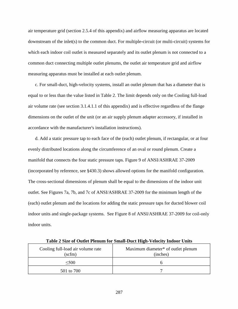
287
air temperature grid (section 2.5.4 of this appendix) and airflow measuring apparatus are located
downstream of the inlet(s) to the common duct. For multiple-circuit (or multi-circuit) systems for
which each indoor coil outlet is measured separately and its outlet plenum is not connected to a
common duct connecting multiple outlet plenums, the outlet air temperature grid and airflow
measuring apparatus must be installed at each outlet plenum.
c. For small-duct, high-velocity systems, install an outlet plenum that has a diameter that is
equal to or less than the value listed in Table 2. The limit depends only on the Cooling full-load
air volume rate (see section 3.1.4.1.1 of this appendix) and is effective regardless of the flange
dimensions on the outlet of the unit (or an air supply plenum adapter accessory, if installed in
accordance with the manufacturer's installation instructions).
d. Add a static pressure tap to each face of the (each) outlet plenum, if rectangular, or at four
evenly distributed locations along the circumference of an oval or round plenum. Create a
manifold that connects the four static pressure taps. Figure 9 of ANSI/ASHRAE 37-2009
(incorporated by reference, see §430.3) shows allowed options for the manifold configuration.
The cross-sectional dimensions of plenum shall be equal to the dimensions of the indoor unit
outlet. See Figures 7a, 7b, and 7c of ANSI/ASHRAE 37-2009 for the minimum length of the
(each) outlet plenum and the locations for adding the static pressure taps for ducted blower coil
indoor units and single-package systems. See Figure 8 of ANSI/ASHRAE 37-2009 for coil-only
indoor units.
Table 2 Size of Outlet Plenum for Small-Duct High-Velocity Indoor Units
Cooling full-load air volume rate (scfm)
Maximum diameter* of outlet plenum (inches)
≤500 6
501 to 700 7

288
701 to 900 8
901 to 1100 9
1101 to 1400 10
1401 to 1750 11 *If the outlet plenum is rectangular, calculate its equivalent diameter using (4A/P,) where A is
the cross-sectional area and P is the perimeter of the rectangular plenum, and compare it to the
listed maximum diameter.
2.4.2 Inlet plenum for the indoor unit.
Install an inlet plenum when testing a coil-only indoor unit, a ducted blower coil indoor unit,
or a single-package system. See Figures 7b and 7c of ANSI/ASHRAE 37-2009 for cross-
sectional dimensions, the minimum length of the inlet plenum, and the locations of the static-
pressure taps for ducted blower coil indoor units and single-package systems. See Figure 8 of
ANSI/ASHRAE 37-2009 for coil-only indoor units. The inlet plenum duct size shall equal the
size of the inlet opening of the air-handling (blower coil) unit or furnace. For a ducted blower
coil indoor unit the set up may omit the inlet plenum if an inlet airflow prevention device is
installed with a straight internally unobstructed duct on its outlet end with a minimum length
equal to 1.5 times the square root of the cross-sectional area of the indoor unit inlet. See section
2.5.1.2 of this appendix for requirements for the locations of static pressure taps built into the
inlet airflow prevention device. For all of these arrangements, make a manifold that connects the
four static-pressure taps using one of the three configurations specified in section 2.4.1.d of this
appendix. Never use an inlet plenum when testing non-ducted indoor units.
2.5 Indoor coil air property measurements and airflow prevention devices.
Follow instructions for indoor coil air property measurements as described in section 2.14 of
this appendix, unless otherwise instructed in this section.

289
a. Measure the dry-bulb temperature and water vapor content of the air entering and leaving
the indoor coil. If needed, use an air sampling device to divert air to a sensor(s) that measures the
water vapor content of the air. See section 5.3 of ANSI/ASHRAE 41.1-2013 (incorporated by
reference, see § 430.3) for guidance on constructing an air sampling device. No part of the air
sampling device or the tubing transferring the sampled air to the sensor shall be within two
inches of the test chamber floor, and the transfer tubing shall be insulated. The sampling device
may also be used for measurement of dry bulb temperature by transferring the sampled air to a
remotely located sensor(s). The air sampling device and the remotely located temperature
sensor(s) may be used to determine the entering air dry bulb temperature during any test. The air
sampling device and the remotely located sensor(s) may be used to determine the leaving air dry
bulb temperature for all tests except:
(1) Cyclic tests; and
(2) Frost accumulation tests.
b. Install grids of temperature sensors to measure dry bulb temperatures of both the entering
and leaving airstreams of the indoor unit. These grids of dry bulb temperature sensors may be
used to measure average dry bulb temperature entering and leaving the indoor unit in all cases
(as an alternative to the dry bulb sensor measuring the sampled air). The leaving airstream grid
is required for measurement of average dry bulb temperature leaving the indoor unit for the two
special cases noted above. The grids are also required to measure the air temperature distribution
of the entering and leaving airstreams as described in sections 3.1.8 and 3.1.9 of this appendix.
Two such grids may applied as a thermopile, to directly obtain the average temperature
difference rather than directly measuring both entering and leaving average temperatures.

290
c. Use of airflow prevention devices. Use an inlet and outlet air damper box, or use an inlet
upturned duct and an outlet air damper box when conducting one or both of the cyclic tests listed
in sections 3.2 and 3.6 of this appendix on ducted systems. If not conducting any cyclic tests, an
outlet air damper box is required when testing ducted and non-ducted heat pumps that cycle off
the indoor blower during defrost cycles and there is no other means for preventing natural or
forced convection through the indoor unit when the indoor blower is off. Never use an inlet
damper box or an inlet upturned duct when testing non-ducted indoor units. An inlet upturned
duct is a length of ductwork installed upstream from the inlet such that the indoor duct inlet
opening, facing upwards, is sufficiently high to prevent natural convection transfer out of the
duct. If an inlet upturned duct is used, install a dry bulb temperature sensor near the inlet opening
of the indoor duct at a centerline location not higher than the lowest elevation of the duct edges
at the inlet, and ensure that any pair of 5-minute averages of the dry bulb temperature at this
location, measured at least every minute during the compressor OFF period of the cyclic test, do
not differ by more than 1.0 °F.
2.5.1 Test set-up on the inlet side of the indoor coil: for cases where the inlet airflow prevention
device is installed.
a. Install an airflow prevention device as specified in section 2.5.1.1 or 2.5.1.2 of this
appendix, whichever applies.
b. For an inlet damper box, locate the grid of entering air dry-bulb temperature sensors, if
used, and the air sampling device, or the sensor used to measure the water vapor content of the
inlet air, at a location immediately upstream of the damper box inlet. For an inlet upturned duct,
locate the grid of entering air dry-bulb temperature sensors, if used, and the air sampling device,
or the sensor used to measure the water vapor content of the inlet air, at a location at least one

291
foot downstream from the beginning of the insulated portion of the duct but before the static
pressure measurement.
2.5.1.1 If the section 2.4.2 inlet plenum is installed.
Construct the airflow prevention device having a cross-sectional flow area equal to or greater
than the flow area of the inlet plenum. Install the airflow prevention device upstream of the inlet
plenum and construct ductwork connecting it to the inlet plenum. If needed, use an adaptor plate
or a transition duct section to connect the airflow prevention device with the inlet plenum.
Insulate the ductwork and inlet plenum with thermal insulation that has a nominal overall
resistance (R-value) of at least 19 hr • ft2 • °F/Btu.
2.5.1.2 If the section 2.4.2 inlet plenum is not installed.
Construct the airflow prevention device having a cross-sectional flow area equal to or greater
than the flow area of the air inlet of the indoor unit. Install the airflow prevention device
immediately upstream of the inlet of the indoor unit. If needed, use an adaptor plate or a short
transition duct section to connect the airflow prevention device with the unit’s air inlet. Add
static pressure taps at the center of each face of a rectangular airflow prevention device, or at
four evenly distributed locations along the circumference of an oval or round airflow prevention
device. Locate the pressure taps at a distance from the indoor unit inlet equal to 0.5 times the
square root of the cross sectional area of the indoor unit inlet. This location must be between the
damper and the inlet of the indoor unit, if a damper is used. Make a manifold that connects the
four static pressure taps using one of the configurations shown in Figure 9 of ANSI/ASHRAE
37-2009 (incorporated by reference, see §430.3). Insulate the ductwork with thermal insulation
that has a nominal overall resistance (R-value) of at least 19 hr•ft2 • °F/Btu.

292
2.5.2 Test set-up on the inlet side of the indoor unit: for cases where no airflow prevention
device is installed.
If using the section 2.4.2 inlet plenum and a grid of dry bulb temperature sensors, mount the
grid at a location upstream of the static pressure taps described in section 2.4.2 of this appendix,
preferably at the entrance plane of the inlet plenum. If the section 2.4.2 inlet plenum is not used
(i.e. for non-ducted units) locate a grid approximately 6 inches upstream of the indoor unit inlet.
In the case of a system having multiple non-ducted indoor units, do this for each indoor unit.
Position an air sampling device, or the sensor used to measure the water vapor content of the
inlet air, immediately upstream of the (each) entering air dry-bulb temperature sensor grid. If a
grid of sensors is not used, position the entering air sampling device (or the sensor used to
measure the water vapor content of the inlet air) as if the grid were present.
2.5.3 Indoor coil static pressure difference measurement.
Fabricate pressure taps meeting all requirements described in section 6.5.2 of
ANSI/ASHRAE 37-2009 (incorporated by reference, see §430.3) and illustrated in Figure 2A of
AMCA 210-2007 (incorporated by reference, see §430.3), however, if adhering strictly to the
description in section 6.5.2 of ANSI/ASHRAE 37-2009, the minimum pressure tap length of 2.5
times the inner diameter of Figure 2A of AMCA 210-2007 is waived. Use a differential pressure
measuring instrument that is accurate to within ±0.01 inches of water and has a resolution of at
least 0.01 inches of water to measure the static pressure difference between the indoor coil air
inlet and outlet. Connect one side of the differential pressure instrument to the manifolded
pressure taps installed in the outlet plenum. Connect the other side of the instrument to the
manifolded pressure taps located in either the inlet plenum or incorporated within the airflow
293
prevention device. For non-ducted indoor units that are tested with multiple outlet plenums,
measure the static pressure within each outlet plenum relative to the surrounding atmosphere.
2.5.4 Test set-up on the outlet side of the indoor coil.
a. Install an interconnecting duct between the outlet plenum described in section 2.4.1 of this
appendix and the airflow measuring apparatus described below in section 2.6 of this appendix.
The cross-sectional flow area of the interconnecting duct must be equal to or greater than the
flow area of the outlet plenum or the common duct used when testing non-ducted units having
multiple indoor coils. If needed, use adaptor plates or transition duct sections to allow the
connections. To minimize leakage, tape joints within the interconnecting duct (and the outlet
plenum). Construct or insulate the entire flow section with thermal insulation having a nominal
overall resistance (R-value) of at least 19 hr·ft2· °F/Btu.
b. Install a grid(s) of dry-bulb temperature sensors inside the interconnecting duct. Also,
install an air sampling device, or the sensor(s) used to measure the water vapor content of the
outlet air, inside the interconnecting duct. Locate the dry-bulb temperature grid(s) upstream of
the air sampling device (or the in-duct sensor(s) used to measure the water vapor content of the
outlet air). Turn off the sampler fan motor during the cyclic tests. Air leaving an indoor unit that
is sampled by an air sampling device for remote water-vapor-content measurement must be
returned to the interconnecting duct at a location:
(1) Downstream of the air sampling device;
(2) On the same side of the outlet air damper as the air sampling device; and
(3) Upstream of the section 2.6 airflow measuring apparatus.
2.5.4.1 Outlet air damper box placement and requirements.
294
If using an outlet air damper box (see section 2.5 of this appendix), the leakage rate from the
combination of the outlet plenum, the closed damper, and the duct section that connects these
two components must not exceed 20 cubic feet per minute when a negative pressure of 1 inch of
water column is maintained at the plenum's inlet.
2.5.4.2 Procedures to minimize temperature maldistribution.
Use these procedures if necessary to correct temperature maldistributions. Install a mixing
device(s) upstream of the outlet air, dry-bulb temperature grid (but downstream of the outlet
plenum static pressure taps). Use a perforated screen located between the mixing device and the
dry-bulb temperature grid, with a maximum open area of 40 percent. One or both items should
help to meet the maximum outlet air temperature distribution specified in section 3.1.8 of this
appendix. Mixing devices are described in sections 5.3.2 and 5.3.3 of ANSI/ASHRAE 41.1-
2013 and section 5.2.2 of ASHRAE 41.2-1987 (RA 1992) (incorporated by reference, see §
430.3).
2.5.4.3 Minimizing air leakage.
For small-duct, high-velocity systems, install an air damper near the end of the
interconnecting duct, just prior to the transition to the airflow measuring apparatus of section 2.6
of this appendix. To minimize air leakage, adjust this damper such that the pressure in the
receiving chamber of the airflow measuring apparatus is no more than 0.5 inch of water higher
than the surrounding test room ambient. If applicable, in lieu of installing a separate damper, use
the outlet air damper box of sections 2.5 and 2.5.4.1 of this appendix if it allows variable
positioning. Also apply these steps to any conventional indoor blower unit that creates a static
pressure within the receiving chamber of the airflow measuring apparatus that exceeds the test
room ambient pressure by more than 0.5 inches of water column.

295
2.5.5 Dry bulb temperature measurement.
a. Measure dry bulb temperatures as specified in sections 4, 5.3, 6, and 7 of ANSI/ASHRAE
41.1-2013 (incorporated by reference, see § 430.3).
b. Distribute the sensors of a dry-bulb temperature grid over the entire flow area. The
required minimum is 9 sensors per grid.
2.5.6 Water vapor content measurement.
Determine water vapor content by measuring dry-bulb temperature combined with the air
wet-bulb temperature, dew point temperature, or relative humidity. If used, construct and apply
wet-bulb temperature sensors as specified in sections 4, 5, 6, 7.2, 7.3, and 7.4 of ASHRAE 41.6-
2014 (incorporated by reference, see §430.3). The temperature sensor (wick removed) must be
accurate to within ±0.2 °F. If used, apply dew point hygrometers as specified in sections 4, 5, 6,
7.1, and 7.4 of ASHRAE 41.6-2014 (incorporated by reference, see § 430.3). The dew point
hygrometers must be accurate to within ±0.4 °F when operated at conditions that result in the
evaluation of dew points above 35 °F. If used, a relative humidity (RH) meter must be accurate
to within ±0.7% RH. Other means to determine the psychrometric state of air may be used as
long as the measurement accuracy is equivalent to or better than the accuracy achieved from
using a wet-bulb temperature sensor that meets the above specifications.
2.5.7 Air damper box performance requirements.
If used (see section 2.5 of this appendix), the air damper box(es) must be capable of being
completely opened or completely closed within 10 seconds for each action.
2.6 Airflow measuring apparatus.
a. Fabricate and operate an airflow measuring apparatus as specified in section 6.2 and 6.3 of
ANSI/ASHRAE 37-2009 (incorporated by reference, see § 430.3). Place the static pressure taps

296
and position the diffusion baffle (settling means) relative to the chamber inlet as indicated in
Figure 12 of AMCA 210-2007 and/or Figure 14 of ASHRAE 41.2-1987 (RA 1992)
(incorporated by reference, see §430.3). When measuring the static pressure difference across
nozzles and/or velocity pressure at nozzle throats using electronic pressure transducers and a data
acquisition system, if high frequency fluctuations cause measurement variations to exceed the
test tolerance limits specified in section 9.2 and Table 2 of ANSI/ASHRAE 37-2009, dampen the
measurement system such that the time constant associated with response to a step change in
measurement (time for the response to change 63% of the way from the initial output to the final
output) is no longer than five seconds.
b. Connect the airflow measuring apparatus to the interconnecting duct section described in
section 2.5.4 of this appendix. See sections 6.1.1, 6.1.2, and 6.1.4, and Figures 1, 2, and 4 of
ANSI/ASHRAE 37-2009; and Figures D1, D2, and D4 of AHRI 210/240-2008 (incorporated by
reference, see §430.3) for illustrative examples of how the test apparatus may be applied within a
complete laboratory set-up. Instead of following one of these examples, an alternative set-up
may be used to handle the air leaving the airflow measuring apparatus and to supply properly
conditioned air to the test unit's inlet. The alternative set-up, however, must not interfere with the
prescribed means for measuring airflow rate, inlet and outlet air temperatures, inlet and outlet
water vapor contents, and external static pressures, nor create abnormal conditions surrounding
the test unit. (Note: Do not use an enclosure as described in section 6.1.3 of ANSI/ASHRAE 37-
2009 when testing triple-split units.)
2.7 Electrical voltage supply.
Perform all tests at the voltage specified in section 6.1.3.2 of AHRI 210/240-2008
(incorporated by reference, see §430.3) for “Standard Rating Tests.” If either the indoor or the

297
outdoor unit has a 208V or 200V nameplate voltage and the other unit has a 230V nameplate
rating, select the voltage supply on the outdoor unit for testing. Otherwise, supply each unit with
its own nameplate voltage. Measure the supply voltage at the terminals on the test unit using a
volt meter that provides a reading that is accurate to within ±1.0 percent of the measured
quantity.
2.8 Electrical power and energy measurements.
a. Use an integrating power (watt-hour) measuring system to determine the electrical energy
or average electrical power supplied to all components of the air conditioner or heat pump
(including auxiliary components such as controls, transformers, crankcase heater, integral
condensate pump on non-ducted indoor units, etc.). The watt-hour measuring system must give
readings that are accurate to within ±0.5 percent. For cyclic tests, this accuracy is required during
both the ON and OFF cycles. Use either two different scales on the same watt-hour meter or two
separate watt-hour meters. Activate the scale or meter having the lower power rating within 15
seconds after beginning an OFF cycle. Activate the scale or meter having the higher power rating
within 15 seconds prior to beginning an ON cycle. For ducted blower coil systems, the ON cycle
lasts from compressor ON to indoor blower OFF. For ducted coil-only systems, the ON cycle
lasts from compressor ON to compressor OFF. For non-ducted units, the ON cycle lasts from
indoor blower ON to indoor blower OFF. When testing air conditioners and heat pumps having a
variable-speed compressor, avoid using an induction watt/watt-hour meter.
b. When performing section 3.5 and/or 3.8 cyclic tests on non-ducted units, provide
instrumentation to determine the average electrical power consumption of the indoor blower
motor to within ±1.0 percent. If required according to sections 3.3, 3.4, 3.7, 3.9.1 of this
appendix, and/or 3.10 of this appendix, this same instrumentation requirement (to determine the

298
average electrical power consumption of the indoor blower motor to within ±1.0 percent) applies
when testing air conditioners and heat pumps having a variable-speed constant-air-volume-rate
indoor blower or a variable-speed, variable-air-volume-rate indoor blower.
2.9 Time measurements.
Make elapsed time measurements using an instrument that yields readings accurate to within
±0.2 percent.
2.10 Test apparatus for the secondary space conditioning capacity measurement.
For all tests, use the indoor air enthalpy method to measure the unit's capacity. This method
uses the test set-up specified in sections 2.4 to 2.6 of this appendix. In addition, for all steady-
state tests, conduct a second, independent measurement of capacity as described in section 3.1.1
of this appendix. For split systems, use one of the following secondary measurement methods:
outdoor air enthalpy method, compressor calibration method, or refrigerant enthalpy method. For
single-package units, use either the outdoor air enthalpy method or the compressor calibration
method as the secondary measurement.
2.10.1 Outdoor Air Enthalpy Method.
a. To make a secondary measurement of indoor space conditioning capacity using the
outdoor air enthalpy method, do the following:
(1) Measure the electrical power consumption of the test unit;
(2) Measure the air-side capacity at the outdoor coil; and
(3) Apply a heat balance on the refrigerant cycle.
b. The test apparatus required for the outdoor air enthalpy method is a subset of the apparatus
used for the indoor air enthalpy method. Required apparatus includes the following:

299
(1) On the outlet side, an outlet plenum containing static pressure taps (sections 2.4,
2.4.1, and 2.5.3 of this appendix),
(2) An airflow measuring apparatus (section 2.6 of this appendix),
(3) A duct section that connects these two components and itself contains the
instrumentation for measuring the dry-bulb temperature and water vapor content of the air
leaving the outdoor coil (sections 2.5.4, 2.5.5, and 2.5.6 of this appendix), and
(4) On the inlet side, a sampling device and temperature grid (section 2.11.b of this
appendix).
c. During the preliminary tests described in sections 3.11.1 and 3.11.1.1 of this appendix,
measure the evaporator and condenser temperatures or pressures. On both the outdoor coil and
the indoor coil, solder a thermocouple onto a return bend located at or near the midpoint of each
coil or at points not affected by vapor superheat or liquid subcooling. Alternatively, if the test
unit is not sensitive to the refrigerant charge, install pressure gages to the access valves or to
ports created from tapping into the suction and discharge lines according to sections 7.4.2 and
8.2.5 of ASHRAE 37–2009. Use this alternative approach when testing a unit charged with a
zeotropic refrigerant having a temperature glide in excess of 1 °F at the specified test conditions.
2.10.2 Compressor Calibration Method.
Measure refrigerant pressures and temperatures to determine the evaporator superheat and
the enthalpy of the refrigerant that enters and exits the indoor coil. Determine refrigerant flow
rate or, when the superheat of the refrigerant leaving the evaporator is less than 5 °F, total
capacity from separate calibration tests conducted under identical operating conditions. When
using this method, install instrumentation and measure refrigerant properties according to section
7.4.2 and 8.2.5 of ANSI/ASHRAE 37-2009 (incorporated by reference, see §430.3). If removing

300
the refrigerant before applying refrigerant lines and subsequently recharging, use the steps in
7.4.2 of ANSI/ASHRAE 37-2009 in addition to the methods of section 2.2.5 of this appendix to
confirm the refrigerant charge . Use refrigerant temperature and pressure measuring instruments
that meet the specifications given in sections 5.1.1 and 5.2 of ANSI/ASHRAE 37-2009.
2.10.3 Refrigerant Enthalpy Method.
For this method, calculate space conditioning capacity by determining the refrigerant
enthalpy change for the indoor coil and directly measuring the refrigerant flow rate. Use section
7.5.2 of ANSI/ASHRAE 37-2009 (incorporated by reference, see §430.3) for the requirements
for this method, including the additional instrumentation requirements, and information on
placing the flow meter and a sight glass. Use refrigerant temperature, pressure, and flow
measuring instruments that meet the specifications given in sections 5.1.1, 5.2, and 5.5.1 of
ANSI/ASHRAE 37-2009. Refrigerant flow measurement device(s), if used, must be either
elevated at least two feet from the test chamber floor or placed upon insulating material having a
total thermal resistance of at least R-12 and extending at least one foot laterally beyond each side
of the device(s)’ exposed surfaces.
2.11 Measurement of test room ambient conditions.
Follow instructions for setting up air sampling device and aspirating psychrometer as
described in section 2.14 of this appendix, unless otherwise instructed in this section.
a. If using a test set-up where air is ducted directly from the conditioning apparatus to the
indoor coil inlet (see Figure 2, Loop Air-Enthalpy Test Method Arrangement, of
ANSI/ASHRAE 37-2009 (incorporated by reference, see §430.3)), add instrumentation to permit
measurement of the indoor test room dry-bulb temperature.

301
b. On the outdoor side, use one of the following two approaches, except that approach (1) is
required for all evaporatively-cooled units and units that transfer condensate to the outdoor unit
for evaporation using condenser heat.
(1) Use sampling tree air collection on all air-inlet surfaces of the outdoor unit.
(2) Use sampling tree air collection on one or more faces of the outdoor unit and
demonstrate air temperature uniformity as follows. Install a grid of evenly-distributed
thermocouples on each air-permitting face on the inlet of the outdoor unit. Install the
thermocouples on the air sampling device, locate them individually or attach them to a wire
structure. If not installed on the air sampling device, install the thermocouple grid 6 to 24
inches from the unit. The thermocouples shall be evenly spaced across the coil inlet surface
and be installed to avoid sampling of discharge air or blockage of air recirculation. The grid
of thermocouples must provide at least 16 measuring points per face or one measurement per
square foot of inlet face area, whichever is less. This grid must be constructed and used as
per section 5.3 of ANSI/ASHRAE 41.1-2013 (incorporated by reference, see §430.3). The
maximum difference between the readings of any two pairs of these individual
thermocouples located at any of the faces of the inlet of the outdoor unit, must not exceed
2.0˚F, otherwise approach (1) must be used.
The air sampling devices shall be located at the geometric center of each side; the branches
may be oriented either parallel or perpendicular to the longer edges of the air inlet area. The air
sampling devices in the outdoor air inlet location shall be sized such that they cover at least 75%
of the face area of the side of the coil that they are measuring.
Air distribution at the test facility point of supply to the unit shall be reviewed and may
require remediation prior to the beginning of testing. Mixing fans can be used to ensure

302
adequate air distribution in the test room. If used, mixing fans shall be oriented such that they
are pointed away from the air intake so that the mixing fan exhaust does not affect the outdoor
coil air volume rate. Particular attention should be given to prevent the mixing fans from
affecting (enhancing or limiting) recirculation of condenser fan exhaust air back through the unit.
Any fan used to enhance test room air mixing shall not cause air velocities in the vicinity of the
test unit to exceed 500 feet per minute.
The air sampling device may be larger than the face area of the side being measured,
however care shall be taken to prevent discharge air from being sampled. If an air sampling
device dimension extends beyond the inlet area of the unit, holes shall be blocked in the air
sampling device to prevent sampling of discharge air. Holes can be blocked to reduce the region
of coverage of the intake holes both in the direction of the trunk axis or perpendicular to the
trunk axis. For intake hole region reduction in the direction of the trunk axis, block holes of one
or more adjacent pairs of branches (the branches of a pair connect opposite each other at the
same trunk location) at either the outlet end or the closed end of the trunk. For intake hole region
reduction perpendicular to the trunk axis, block off the same number of holes on each branch on
both sides of the trunk.
A maximum of four (4) air sampling devices shall be connected to each aspirating
psychrometer. In order to proportionately divide the flow stream for multiple air sampling
devices for a given aspirating psychrometer, the tubing or conduit conveying sampled air to the
psychrometer shall be of equivalent lengths for each air sampling device. Preferentially, the air
sampling device should be hard connected to the aspirating psychrometer, but if space
constraints do not allow this, the assembly shall have a means of allowing a flexible tube to
connect the air sampling device to the aspirating psychrometer. The tubing or conduit shall be

303
insulated and routed to prevent heat transfer to the air stream. Any surface of the air conveying
tubing in contact with surrounding air at a different temperature than the sampled air shall be
insulated with thermal insulation with a nominal thermal resistance (R-value) of at least 19 hr •
ft2 • °F/Btu. Alternatively the conduit may have lower thermal resistance if additional sensor(s)
are used to measure dry bulb temperature at the outlet of each air sampling device. No part of
the air sampling device or the tubing conducting the sampled air to the sensors shall be within
two inches of the test chamber floor.
Pairs of measurements (e.g. dry bulb temperature and wet bulb temperature) used to
determine water vapor content of sampled air shall be measured in the same location.
2.12 Measurement of indoor blower speed.
When required, measure fan speed using a revolution counter, tachometer, or stroboscope
that gives readings accurate to within ±1.0 percent.
2.13 Measurement of barometric pressure.
Determine the average barometric pressure during each test. Use an instrument that meets the
requirements specified in section 5.2 of ANSI/ASHRAE 37-2009 (incorporated by reference, see
§430.3).
2.14 Air sampling device and aspirating psycrhometer requirements
Air temperature measurements shall be made in accordance with ANSI/ASHRAE 41.1-2013,
unless otherwise instructed in this section.
2.14.1 Air sampling device requirements.
The air sampling device is intended to draw in a sample of the air at the critical locations of a
unit under test. It shall be constructed of stainless steel, plastic or other suitable, durable
materials. It shall have a main flow trunk tube with a series of branch tubes connected to the

304
trunk tube. Holes shall be on the side of the sampler facing the upstream direction of the air
source. Other sizes and rectangular shapes can be used, and shall be scaled accordingly with the
following guidelines:
(1) Minimum hole density of 6 holes per square foot of area to be sampled
(2) Sampler branch tube pitch (spacing) of 6 ± 3 in
(3) Manifold trunk to branch diameter ratio having a minimum of 3:1 ratio
(4) Hole pitch (spacing) shall be equally distributed over the branch (1/2 pitch from the
closed end to the nearest hole)
(5) Maximum individual hole to branch diameter ratio of 1:2 (1:3 preferred)
The minimum average velocity through the air sampling device holes shall be 2.5 ft/s as
determined by evaluating the sum of the open area of the holes as compared to the flow area in
the aspirating psychrometer.
2.14.2 Aspirating psychrometer.
The psychrometer consists of a flow section and a fan to draw air through the flow section
and measures an average value of the sampled air stream. At a minimum, the flow section shall
have a means for measuring the dry bulb temperature (typically, a resistance temperature device
(RTD) and a means for measuring the humidity (RTD with wetted sock, chilled mirror
hygrometer, or relative humidity sensor). The aspirating psychrometer shall include a fan that
either can be adjusted manually or automatically to maintain required velocity across the sensors.
The psychrometer shall be made from suitable material which may be plastic (such as
polycarbonate), aluminum or other metallic materials. All psychrometers for a given system
being tested, shall be constructed of the same material. Psychrometers shall be designed such
305
that radiant heat from the motor (for driving the fan that draws sampled air through the
psychrometer) does not affect sensor measurements. For aspirating psychrometers, velocity
across the wet bulb sensor shall be 1000 ± 200 ft/min. For all other psychrometers, velocity shall
be as specified by the sensor manufacturer.
3. Testing Procedures
3.1 General Requirements.
If, during the testing process, an equipment set-up adjustment is made that would have
altered the performance of the unit during any already completed test, then repeat all tests
affected by the adjustment. For cyclic tests, instead of maintaining an air volume rate, for each
airflow nozzle, maintain the static pressure difference or velocity pressure during an ON period
at the same pressure difference or velocity pressure as measured during the steady-state test
conducted at the same test conditions.
Use the testing procedures in this section to collect the data used for calculating
(1) Performance metrics for central air conditioners and heat pumps during the cooling
season;
(2) Performance metrics for heat pumps during the heating season; and
(3) Power consumption metric(s) for central air conditioners and heat pumps during the
off mode season(s).
3.1.1 Primary and secondary test methods.
For all tests, use the indoor air enthalpy method test apparatus to determine the unit's space
conditioning capacity. The procedure and data collected, however, differ slightly depending upon
whether the test is a steady-state test, a cyclic test, or a frost accumulation test. The following

306
sections described these differences. For all steady-state tests (i.e., the A, A2, A1, B, B2, B1, C,
C1, EV, F1, G1, H01, H1, H12, H11, HIN, H3, H32, and H31 Tests), in addition, use one of the
acceptable secondary methods specified in section 2.10 of this appendix to determine indoor
space conditioning capacity. Calculate this secondary check of capacity according to section
3.11 of this appendix. The two capacity measurements must agree to within 6 percent to
constitute a valid test. For this capacity comparison, use the indoor air enthalpy method capacity
that is calculated in section 7.3 of ANSI/ASHRAE 37-2009 (and, if testing a coil-only system,
compare capacities before before making the after-test fan heat adjustments described in section
3.3, 3.4, 3.7, and 3.10 of this appendix). However, include the appropriate section 3.3 to 3.5 and
3.7 to 3.10 fan heat adjustments within the indoor air enthalpy method capacities used for the
section 4 seasonal calculations of this appendix.
3.1.2 Manufacturer-provided equipment overrides.
Where needed, the manufacturer must provide a means for overriding the controls of the test
unit so that the compressor(s) operates at the specified speed or capacity and the indoor blower
operates at the specified speed or delivers the specified air volume rate.
3.1.3 Airflow through the outdoor coil.
For all tests, meet the requirements given in section 6.1.3.4 of AHRI 210/240-2008
(incorporated by reference, see §430.3) when obtaining the airflow through the outdoor coil.
3.1.3.1 Double-ducted.
For products intended to be installed with the outdoor airflow ducted, the unit shall be
installed with outdoor coil ductwork installed per manufacturer installation instructions and shall
operate between 0.10 and 0.15 in H2O external static pressure. External static pressure
measurements shall be made in accordance with ANSI/ASHRAE 37-2009 section 6.4 and 6.5.

307
3.1.4 Airflow through the indoor coil.
Airflow setting(s) shall be determined before testing begins. Unless otherwise specified
within this or its subsections, no changes shall be made to the airflow setting(s) after initiation of
testing.
3.1.4.1 Cooling full-load air volume rate.
3.1.4.1.1. Cooling full-load air volume rate for Ducted Units.
Identify the certified cooling full-load air volume rate and certified instructions for setting
fan speed or controls. If there is no certified Cooling full-load air volume rate, use a value equal
to the certified cooling capacity of the unit times 400 scfm per 12,000 Btu/h. If there are no
instructions for setting fan speed or controls, use the as-shipped settings. Use the following
procedure to confirm and, if necessary, adjust the Cooling full-load air volume rate and the fan
speed or control settings to meet each test procedure requirement:
a. For all ducted blower coil systems, except those having a constant-air-volume-rate indoor
blower:
Step (1) Operate the unit under conditions specified for the A (for single-stage units) or
A2 test using the certified fan speed or controls settings, and adjust the exhaust fan of the airflow
measuring apparatus to achieve the certified Cooling full-load air volume rate ;
Step (2) Measure the external static pressure;
Step (3) If this external static pressure is equal to or greater than the applicable
minimum external static pressure cited in Table 3, the pressure requirement is satisfied; proceed
to step 7 of this section. If this external static pressure is not equal to or greater than the
applicable minimum external static pressure cited in Table 3, proceed to step 4 of this section;

308
Step (4) Increase the external static pressure by adjusting the exhaust fan of the airflow
measuring apparatus until either
(i) The applicable Table 3 minimum is equaled or
(ii) The measured air volume rate equals 90 percent or less of the Cooling full-load air
volume rate, whichever occurs first;
Step (5) If the conditions of step 4 (i) of this section occur first, the pressure
requirement is satisfied; proceed to step 7 of this section. If the conditions of step 4 (ii) of this
section occur first, proceed to step 6 of this section;
Step (6) Make an incremental change to the setup of the indoor blower (e.g., next
highest fan motor pin setting, next highest fan motor speed) and repeat the evaluation process
beginning above, at step 1 of this section. If the indoor blower setup cannot be further changed,
increase the external static pressure by adjusting the exhaust fan of the airflow measuring
apparatus until the applicable Table 3 minimum is equaled; proceed to step 7 of this section;
Step (7) The airflow constraints have been satisfied. Use the measured air volume rate
as the Cooling full-load air volume rate. Use the final fan speed or control settings for all tests
that use the Cooling full-load air volume rate.
b. For ducted blower coil systems with a constant-air-volume-rate indoor blower. For all tests
that specify the Cooling full-load air volume rate, obtain an external static pressure as close to
(but not less than) the applicable Table 3 value that does not cause automatic shutdown of the
indoor blower or air volume rate variation QVar, defined as follows, greater than 10 percent.
𝑄𝑄𝑉𝑉𝑉𝑉𝑉𝑉 = �𝑄𝑄𝑚𝑚𝑉𝑉𝑚𝑚 − 𝑄𝑄𝑚𝑚𝑖𝑖𝑛𝑛�𝑄𝑄𝑚𝑚𝑎𝑎𝑥𝑥+ 𝑄𝑄𝑚𝑚𝑚𝑚𝑚𝑚
2�� ∗ 100
where:
309
Qmax = maximum measured airflow value
Qmin = minimum measured airflow value
QVar = airflow variance, percent
Additional test steps as described in section 3.3.(e) of this appendix are required if the
measured external static pressure exceeds the target value by more than 0.03 inches of water.
c. For coil-only indoor units. For the A or A2 Test, (exclusively), the pressure drop across
the indoor coil assembly must not exceed 0.30 inches of water. If this pressure drop is exceeded,
reduce the air volume rate until the measured pressure drop equals the specified maximum. Use
this reduced air volume rate for all tests that require the Cooling full-load air volume rate.

310
Table 3 Minimum External Static Pressure for Ducted Blower Coil Systems
Rated Cooling1 or Heating2 Capacity (Btu/h)
Minimum external resistance3 (Inches of water)
Small-duct, high-
velocity systems4 5
All other
systems
Up Thru 28,800 1.10 0.10
29,000 to 42,500 1.15 0.15
43,000 and Above 1.20 0.20 1For air conditioners and air-conditioning heat pumps, the value certified by the manufacturer for
the unit's cooling capacity when operated at the A or A2 Test conditions.
2For heating-only heat pumps, the value certified by the manufacturer for the unit's heating
capacity when operated at the H1 or H12 Test conditions.
3For ducted units tested without an air filter installed, increase the applicable tabular value by
0.08 inches of water.
4See section 1.2 of this appendix, Definitions, to determine if the equipment qualifies as a small-
duct, high-velocity system.
5If a closed-loop, air-enthalpy test apparatus is used on the indoor side, limit the resistance to
airflow on the inlet side of the blower coil indoor unit to a maximum value of 0.1 inch of water.
Impose the balance of the airflow resistance on the outlet side of the indoor blower.
d. For ducted systems having multiple indoor blowers within a single indoor section, obtain
the full-load air volume rate with all indoor blowers operating unless prevented by the controls
of the unit. In such cases, turn on the maximum number of indoor blowers permitted by the
unit’s controls. Where more than one option exists for meeting this “on” indoor blower
requirement, which indoor blower(s) are turned on must match that specified in the certification
report. Conduct section 3.1.4.1.1 setup steps for each indoor blower separately. If two or more

311
indoor blowers are connected to a common duct as per section 2.4.1 of this appendix,
temporarily divert their air volume to the test room when confirming or adjusting the setup
configuration of individual indoor blowers. The allocation of the system’s full-load air volume
rate assigned to each “on” indoor blower must match that specified by the manufacturer in the
certification report.
3.1.4.1.2. Cooling full-load air volume rate for Non-ducted Units.
For non-ducted units, the Cooling full-load air volume rate is the air volume rate that results
during each test when the unit is operated at an external static pressure of zero inches of water.
3.1.4.2 Cooling Minimum Air Volume Rate.
Identify the certified cooling minimum air volume rate and certified instructions for setting
fan speed or controls. If there is no certified cooling minimum air volume rate, use the final
indoor blower control settings as determined when setting the cooling full-load air volume rate,
and readjust the exhaust fan of the airflow measuring apparatus if necessary to reset to the
cooling full load air volume obtained in section 3.1.4.1 of this appendix. Otherwise, calculate the
target external static pressure and follow instructions a, b, c, d, or e below. The target external
static pressure, ΔPst_i, for any test “i” with a specified air volume rate not equal to the Cooling
full-load air volume rate is determined as follows:
∆𝑃𝑃𝑠𝑠𝐵𝐵_𝑖𝑖 = ∆𝑃𝑃𝑠𝑠𝐵𝐵_𝑓𝑓𝐵𝐵𝑓𝑓𝑓𝑓 �𝑄𝑄𝑖𝑖𝑄𝑄𝑓𝑓𝐵𝐵𝑓𝑓𝑓𝑓
�2
where:
ΔPst_i = target minimum external static pressure for test i;
ΔPst_full = minimum external static pressure for test A or A2 (Table 3);
Qi = air volume rate for test i; and

312
Qfull = Cooling full-load air volume rate as measured after setting and/or adjustment as
described in section 3.1.4.1.1 of this appendix.
a. For a ducted blower coil system without a constant-air-volume indoor blower, adjust for
external static pressure as follows:
Step (1) Operate the unit under conditions specified for the B1 test using the certified
fan speed or controls settings, and adjust the exhaust fan of the airflow measuring apparatus to
achieve the certified cooling minimum air volume rate;
Step (2) Measure the external static pressure;
Step (3) If this pressure is equal to or greater than the minimum external static
pressure computed above, the pressure requirement is satisfied; proceed to step 7 of this section.
If this pressure is not equal to or greater than the minimum external static pressure computed
above, proceed to step 4 of this section;
Step (4) Increase the external static pressure by adjusting the exhaust fan of the
airflow measuring apparatus until either
(i) The pressure is equal to the minimum external static pressure computed above or
(ii) The measured air volume rate equals 90 percent or less of the cooling minimum air
volume rate, whichever occurs first;
Step (5) If the conditions of step 4 (i) of this section occur first, the pressure
requirement is satisfied; proceed to step 7 of this section. If the conditions of step 4 (ii) of this
section occur first, proceed to step 6 of this section;
Step (6) Make an incremental change to the setup of the indoor blower (e.g., next
highest fan motor pin setting, next highest fan motor speed) and repeat the evaluation process
beginning above, at step 1 of this section. If the indoor blower setup cannot be further changed,

313
increase the external static pressure by adjusting the exhaust fan of the airflow measuring
apparatus until it equals the minimum external static pressure computed above; proceed to step 7
of this section;
Step (7) The airflow constraints have been satisfied. Use the measured air volume rate
as the cooling minimum air volume rate. Use the final fan speed or control settings for all tests
that use the cooling minimum air volume rate.
b. For ducted units with constant-air-volume indoor blowers, conduct all tests that specify the
cooling minimum air volume rate—(i.e., the A1, B1, C1, F1, and G1 Tests)—at an external static
pressure that does not cause an automatic shutdown of the indoor blower or air volume rate
variation QVar, defined in section 3.1.4.1.1.b of this appendix, greater than 10 percent, while
being as close to, but not less than the target minimum external static pressure. Additional test
steps as described in section 3.3(e) of this appendix are required if the measured external static
pressure exceeds the target value by more than 0.03 inches of water.
c. For ducted two-capacity coil-only systems, the cooling minimum air volume rate is the
higher of (1) the rate specified by the installation instructions included with the unit by the
manufacturer or (2) 75 percent of the cooling full-load air volume rate. During the laboratory
tests on a coil-only (fanless) system, obtain this cooling minimum air volume rate regardless of
the pressure drop across the indoor coil assembly.
d. For non-ducted units, the cooling minimum air volume rate is the air volume rate that
results during each test when the unit operates at an external static pressure of zero inches of
water and at the indoor blower setting used at low compressor capacity (two-capacity system) or
minimum compressor speed (variable-speed system). For units having a single-speed

314
compressor and a variable-speed variable-air-volume-rate indoor blower, use the lowest fan
setting allowed for cooling.
e. For ducted systems having multiple indoor blowers within a single indoor section, operate
the indoor blowers such that the lowest air volume rate allowed by the unit’s controls is obtained
when operating the lone single-speed compressor or when operating at low compressor capacity
while meeting the requirements of section 2.2.3.b of this appendix for the minimum number of
blowers that must be turned off. Using the target external static pressure and the certified air
volume rates, follow the procedures described in section 3.1.4.2.a of this appendix if the indoor
blowers are not constant-air-volume indoor blowers or as described in section 3.1.4.2.b of this
appendix if the indoor blowers are constant-air-volume indoor blowers. The sum of the
individual “on” indoor blowers’ air volume rates is the cooling minimum air volume rate for the
system.
3.1.4.3 Cooling Intermediate Air Volume Rate.
Identify the certified cooling intermediate air volume rate and certified instructions for
setting fan speed or controls. If there is no certified cooling intermediate air volume rate, use the
final indoor blower control settings as determined when setting the cooling full load air volume
rate, and readjust the exhaust fan of the airflow measuring apparatus if necessary to reset to the
cooling full load air volume obtained in section 3.1.4.1 of this appendix. Otherwise, calculate
target minimum external static pressure as described in section 3.1.4.2 of this appendix, and set
the air volume rate as follows.
a. For a ducted blower coil system without a constant-air-volume indoor blower, adjust for
external static pressure as described in section 3.1.4.2.a of this appendix for cooling minimum air
volume rate.

315
b. For a ducted blower coil system with a constant-air-volume indoor blower, conduct the
EV Test at an external static pressure that does not cause an automatic shutdown of the indoor
blower or air volume rate variation QVar, defined in section 3.1.4.1.1.b of this appendix, greater
than 10 percent, while being as close to, but not less than the target minimum external static
pressure. Additional test steps as described in section 3.3(e) of this appendix are required if the
measured external static pressure exceeds the target value by more than 0.03 inches of water.
c. For non-ducted units, the cooling intermediate air volume rate is the air volume rate that
results when the unit operates at an external static pressure of zero inches of water and at the fan
speed selected by the controls of the unit for the EV Test conditions.
3.1.4.4 Heating full-load air volume rate.
3.1.4.4.1. Ducted heat pumps where the heating and cooling full-load air volume rates are the
same.
a. Use the Cooling full-load air volume rate as the heating full-load air volume rate for:
(1) Ducted blower coil system heat pumps that do not have a constant-air-volume indoor
blower, and that operate at the same airflow-control setting during both the A (or A2) and the H1
(or H12) Tests;
(2) Ducted blower coil system heat pumps with constant-air-flow indoor blowers that
provide the same air flow for the A (or A2) and the H1 (or H12) Tests; and
(3) Ducted heat pumps that are tested with a coil-only indoor unit (except two-capacity
northern heat pumps that are tested only at low capacity cooling—see section 3.1.4.4.2 of this
appendix).
b. For heat pumps that meet the above criteria “1” and “3,” no minimum requirements apply
to the measured external or internal, respectively, static pressure. Use the final indoor blower
316
control settings as determined when setting the Cooling full-load air volume rate, and readjust
the exhaust fan of the airflow measuring apparatus if necessary to reset to the cooling full-load
air volume obtained in section 3.1.4.1 of this appendix. For heat pumps that meet the above
criterion “2,” test at an external static pressure that does not cause an automatic shutdown of the
indoor blower or air volume rate variation QVar, defined in section 3.1.4.1.1.b of this appendix,
greater than 10 percent, while being as close to, but not less than, the same Table 3 minimum
external static pressure as was specified for the A (or A2) cooling mode test. Additional test steps
as described in section 3.9.1(c) of this appendix are required if the measured external static
pressure exceeds the target value by more than 0.03 inches of water.
3.1.4.4.2. Ducted heat pumps where the heating and cooling full-load air volume rates are
different due to changes in indoor blower operation, i.e. speed adjustment by the system controls.
Identify the certified heating full-load air volume rate and certified instructions for setting fan
speed or controls. If there is no certified heating full-load air volume rate, use the final indoor
blower control settings as determined when setting the cooling full-load air volume rate, and
readjust the exhaust fan of the airflow measuring apparatus if necessary to reset to the cooling
full load air volume obtained in section 3.1.4.1 of this appendix. Otherwise, calculate target
minimum external static pressure as described in section 3.1.4.2 of this appendix and set the air
volume rate as follows.
a. For ducted blower coil system heat pumps that do not have a constant-air-volume indoor
blower, adjust for external static pressure as described in section 3.1.4.2.a of this appendix for
cooling minimum air volume rate.
b. For ducted heat pumps tested with constant-air-volume indoor blowers installed, conduct
all tests that specify the heating full-load air volume rate at an external static pressure that does

317
not cause an automatic shutdown of the indoor blower or air volume rate variation QVar, defined
in section 3.1.4.1.1.b of this appendix, greater than 10 percent, while being as close to, but not
less than the target minimum external static pressure. Additional test steps as described in
section 3.9.1(c) of this appendix are required if the measured external static pressure exceeds the
target value by more than 0.03 inches of water.
c. When testing ducted, two-capacity blower coil system northern heat pumps (see section
1.2 of this appendix, Definitions), use the appropriate approach of the above two cases. For coil-
only system northern heat pumps, the heating full-load air volume rate is the lesser of the rate
specified by the manufacturer in the installation instructions included with the unit or 133
percent of the cooling full-load air volume rate. For this latter case, obtain the heating full-load
air volume rate regardless of the pressure drop across the indoor coil assembly.
d. For ducted systems having multiple indoor blowers within a single indoor section, obtain
the heating full-load air volume rate using the same “on” indoor blowers as used for the Cooling
full-load air volume rate. Using the target external static pressure and the certified air volume
rates, follow the procedures as described in section 3.1.4.4.2.a of this appendix if the indoor
blowers are not constant-air-volume indoor blowers or as described in section 3.1.4.4.2.b of this
appendix if the indoor blowers are constant-air-volume indoor blowers. The sum of the
individual “on” indoor blowers’ air volume rates is the heating full load air volume rate for the
system.
3.1.4.4.3. Ducted heating-only heat pumps.
Identify the certified heating full-load air volume rate and certified instructions for setting fan
speed or controls. If there is no certified heating full-load air volume rate, use a value equal to

318
the certified heating capacity of the unit times 400 scfm per 12,000 Btu/h. If there are no
instructions for setting fan speed or controls, use the as-shipped settings.
a. For all ducted heating-only blower coil system heat pumps, except those having a constant-
air-volume-rate indoor blower. Conduct the following steps only during the first test, the H1 or
H12 est:
Step (1) Adjust the exhaust fan of the airflow measuring apparatus to achieve the
certified heating full-load air volume rate.
Step (2) Measure the external static pressure.
Step (3) If this pressure is equal to or greater than the Table 3 minimum external static
pressure that applies given the heating-only heat pump's rated heating capacity, the pressure
requirement is satisfied; proceed to step 7 of this section. If this pressure is not equal to or greater
than the applicable Table 3 minimum external static pressure, proceed to step 4 of this section;
Step (4) Increase the external static pressure by adjusting the exhaust fan of the
airflow measuring apparatus until either (i) the pressure is equal to the applicable Table 3
minimum external static pressure or (ii) the measured air volume rate equals 90 percent or less of
the heating full-load air volume rate, whichever occurs first;
Step (5) If the conditions of step 4 (i) of this section occur first, the pressure
requirement is satisfied; proceed to step 7 of this section. If the conditions of step 4 (ii) of this
section occur first, proceed to step 6 of this section;
Step (6) Make an incremental change to the setup of the indoor blower (e.g., next
highest fan motor pin setting, next highest fan motor speed) and repeat the evaluation process
beginning above, at step 1 of this section. If the indoor blower setup cannot be further changed,
increase the external static pressure by adjusting the exhaust fan of the airflow measuring

319
apparatus until it equals the applicable Table 3 minimum external static pressure; proceed to step
7 of this section;
Step (7) The airflow constraints have been satisfied. Use the measured air volume rate
as the heating full-load air volume rate. Use the final fan speed or control settings for all tests
that use the heating full-load air volume rate.
b. For ducted heating-only blower coil system heat pumps having a constant-air-volume-rate
indoor blower. For all tests that specify the heating full-load air volume rate, obtain an external
static pressure that does not cause an automatic shutdown of the indoor blower or air volume rate
variation QVar, defined in section 3.1.4.1.1.b of this appendix, greater than 10 percent, while
being as close to, but not less than, the applicable Table 3 minimum. Additional test steps as
described in section 3.9.1(c) of this appendix are required if the measured external static pressure
exceeds the target value by more than 0.03 inches of water.
c. For ducted heating-only coil-only system heat pumps in the H1 or H12 Test, (exclusively),
the pressure drop across the indoor coil assembly must not exceed 0.30 inches of water. If this
pressure drop is exceeded, reduce the air volume rate until the measured pressure drop equals the
specified maximum. Use this reduced air volume rate for all tests that require the heating full-
load air volume rate.
3.1.4.4.4 Non-ducted heat pumps, including non-ducted heating-only heat pumps.
For non-ducted heat pumps, the heating full-load air volume rate is the air volume rate that
results during each test when the unit operates at an external static pressure of zero inches of
water.
3.1.4.5 Heating Minimum Air Volume Rate.

320
3.1.4.5.1. Ducted heat pumps where the heating and cooling minimum air volume rates are the
same.
a. Use the cooling minimum air volume rate as the heating minimum air volume rate for:
(1) Ducted blower coil system heat pumps that do not have a constant-air-volume indoor
blower, and that operates at the same airflow-control setting during both the A1 and the H11 tests;
(2) Ducted blower coil system heat pumps with constant-air-flow indoor blowers
installed that provide the same air flow for the A1 and the H11 Tests; and
(3) Ducted coil-only system heat pumps.
b. For heat pumps that meet the above criteria “1” and “3,” no minimum requirements apply
to the measured external or internal, respectively, static pressure. Use the final indoor blower
control settings as determined when setting the cooling minimum air volume rate, and readjust
the exhaust fan of the airflow measuring apparatus if necessary to reset to the cooling minimum
air volume rate obtained in section 3.1.4.2 of this appendix. For heat pumps that meet the above
criterion “2,” test at an external static pressure that does not cause an automatic shutdown of the
indoor blower or air volume rate variation QVar, defined in section 3.1.4.1.1.b of this appendix,
greater than 10 percent, while being as close to, but not less than, the same target minimum
external static pressure as was specified for the A1 cooling mode test. Additional test steps as
described in section 3.9.1(c) of this appendix are required if the measured external static pressure
exceeds the target value by more than 0.03 inches of water.
3.1.4.5.2. Ducted heat pumps where the heating and cooling minimum air volume rates are
different due changes in indoor blower operation, i.e. speed adjustment by the system controls.
Identify the certified heating minimum air volume rate and certified instructions for setting
fan speed or controls. If there is no certified heating minimum air volume rate, use the final

321
indoor blower control settings as determined when setting the cooling minimum air volume rate,
and readjust the exhaust fan of the airflow measuring apparatus if necessary to reset to the
cooling minimum air volume obtained in section 3.1.4.2 of this appendix. Otherwise, calculate
the target minimum external static pressure as described in section 3.1.4.2 of this appendix.
a. For ducted blower coil system heat pumps that do not have a constant-air-volume indoor
blower, adjust for external static pressure as described in section 3.1.4.2.a of this appendix for
cooling minimum air volume rate.
b. For ducted heat pumps tested with constant-air-volume indoor blowers installed, conduct
all tests that specify the heating minimum air volume rate—(i.e., the H01, H11, H21, and
H31 Tests)—at an external static pressure that does not cause an automatic shutdown of the
indoor blower while being as close to, but not less than the air volume rate variation QVar,
defined in section 3.1.4.1.1.b of this appendix, greater than 10 percent, while being as close to,
but not less than the target minimum external static pressure. Additional test steps as described
in section 3.9.1.c of this appendix are required if the measured external static pressure exceeds
the target value by more than 0.03 inches of water.
c. For ducted two-capacity blower coil system northern heat pumps, use the appropriate
approach of the above two cases.
d. For ducted two-capacity coil-only system heat pumps, use the cooling minimum air
volume rate as the heating minimum air volume rate. For ducted two-capacity coil-only system
northern heat pumps, use the cooling full-load air volume rate as the heating minimum air
volume rate. For ducted two-capacity heating-only coil-only system heat pumps, the heating
minimum air volume rate is the higher of the rate specified by the manufacturer in the test setup
instructions included with the unit or 75 percent of the heating full-load air volume rate. During
322
the laboratory tests on a coil-only system, obtain the heating minimum air volume rate without
regard to the pressure drop across the indoor coil assembly.
e. For non-ducted heat pumps, the heating minimum air volume rate is the air volume rate
that results during each test when the unit operates at an external static pressure of zero inches of
water and at the indoor blower setting used at low compressor capacity (two-capacity system) or
minimum compressor speed (variable-speed system). For units having a single-speed compressor
and a variable-speed, variable-air-volume-rate indoor blower, use the lowest fan setting allowed
for heating.
f. For ducted systems with multiple indoor blowers within a single indoor section, obtain the
heating minimum air volume rate using the same “on” indoor blowers as used for the cooling
minimum air volume rate. Using the target external static pressure and the certified air volume
rates, follow the procedures as described in section 3.1.4.5.2.a of this appendix if the indoor
blowers are not constant-air-volume indoor blowers or as described in section 3.1.4.5.2.b of this
appendix if the indoor blowers are constant-air-volume indoor blowers. The sum of the
individual “on” indoor blowers’ air volume rates is the heating full-load air volume rate for the
system.
3.1.4.6 Heating intermediate air volume rate.
Identify the certified heating intermediate air volume rate and certified instructions for setting
fan speed or controls. If there is no certified heating intermediate air volume rate, use the final
indoor blower control settings as determined when setting the heating full-load air volume rate,
and readjust the exhaust fan of the airflow measuring apparatus if necessary to reset to the
cooling full load air volume obtained in section 3.1.4.2 of this appendix. Calculate the target
minimum external static pressure as described in section 3.1.4.2 of this appendix.

323
a. For ducted blower coil system heat pumps that do not have a constant-air-volume indoor
blower, adjust for external static pressure as described in section 3.1.4.2.a of this appendix for
cooling minimum air volume rate.
b. For ducted heat pumps tested with constant-air-volume indoor blowers installed, conduct
the H2V Test at an external static pressure that does not cause an automatic shutdown of the
indoor blower or air volume rate variation QVar, defined in section 3.1.4.1.1.b of this appendix,
greater than 10 percent, while being as close to, but not less than the target minimum external
static pressure. Additional test steps as described in section 3.9.1(c) of this appendix are required
if the measured external static pressure exceeds the target value by more than 0.03 inches of
water.
c. For non-ducted heat pumps, the heating intermediate air volume rate is the air volume rate
that results when the heat pump operates at an external static pressure of zero inches of water and
at the fan speed selected by the controls of the unit for the H2V Test conditions.
3.1.4.7 Heating Nominal Air Volume Rate.
The manufacturer must specify the heating nominal air volume rate and the instructions for
setting fan speed or controls. Calculate target minimum external static pressure as described in
section 3.1.4.2 of this appendix. Make adjustments as described in section 3.1.4.6 of this
appendix for heating intermediate air volume rate so that the target minimum external static
pressure is met or exceeded.
3.1.5 Indoor test room requirement when the air surrounding the indoor unit is not supplied from
the same source as the air entering the indoor unit.
If using a test set-up where air is ducted directly from the air reconditioning apparatus to the
indoor coil inlet (see Figure 2, Loop Air-Enthalpy Test Method Arrangement, of

324
ANSI/ASHRAE 37-2009 (incorporated by reference, see § 430.3)), maintain the dry bulb
temperature within the test room within ±5.0 °F of the applicable sections 3.2 and 3.6 dry bulb
temperature test condition for the air entering the indoor unit. Dew point shall be within 2 °F of
the required inlet conditions.
3.1.6 Air volume rate calculations.
For all steady-state tests and for frost accumulation (H2, H21, H22, H2V) tests, calculate the
air volume rate through the indoor coil as specified in sections 7.7.2.1 and 7.7.2.2 of
ANSI/ASHRAE 37-2009. When using the outdoor air enthalpy method, follow sections 7.7.2.1
and 7.7.2.2 of ANSI/ASHRAE 37-2009 to calculate the air volume rate through the outdoor
coil. To express air volume rates in terms of standard air, use:
Equation 3-1 𝑉𝑉�̇�𝑠 = �̇�𝑉𝑚𝑚𝑥𝑥������
0.075 𝑙𝑙𝑙𝑙𝑚𝑚𝑑𝑑a𝑓𝑓𝑓𝑓3
∗𝑣𝑣𝑚𝑚′ ∗[1+𝑊𝑊𝑚𝑚]= �̇�𝑉𝑚𝑚𝑥𝑥������
0.075 𝑙𝑙𝑙𝑙𝑚𝑚𝑑𝑑a𝑓𝑓𝑓𝑓3
∗𝑣𝑣𝑚𝑚
where:
V̅̇s = air volume rate of standard (dry) air, (ft3/min)da
V̅̇mx = air volume rate of the air-water vapor mixture, (ft3/min)mx
vn′ = specific volume of air-water vapor mixture at the nozzle, ft3 per lbm of the air-water
vapor mixture
Wn = humidity ratio at the nozzle, lbm of water vapor per lbm of dry air
0.075 = the density associated with standard (dry) air, (lbm/ft3)
vn = specific volume of the dry air portion of the mixture evaluated at the dry-bulb
temperature, vapor content, and barometric pressure existing at the nozzle, ft3 per lbm of
dry air.

325
(Note: In the first printing of ANSI/ASHRAE 37-2009, the second IP equation for
Qmi should read, 𝑄𝑄𝑚𝑚𝑖𝑖 = 1097𝑈𝑈𝐴𝐴𝑛𝑛�𝑃𝑃𝑉𝑉𝑣𝑣𝑛𝑛′
3.1.7 Test sequence.
Manufacturers may optionally operate the equipment under test for a “break-in” period, not
to exceed 20 hours, prior to conducting the test method specified in this section. A manufacturer
who elects to use this optional compressor break-in period in its certification testing should
record this information (including the duration) in the test data underlying the certified ratings
that are required to be maintained under 10 CFR 429.71. When testing a ducted unit (except if a
heating-only heat pump), conduct the A or A2 Test first to establish the cooling full-load air
volume rate. For ducted heat pumps where the heating and cooling full-load air volume rates are
different, make the first heating mode test one that requires the heating full-load air volume rate.
For ducted heating-only heat pumps, conduct the H1 or H12 Test first to establish the heating
full-load air volume rate. When conducting a cyclic test, always conduct it immediately after the
steady-state test that requires the same test conditions. For variable-speed systems, the first test
using the cooling minimum air volume rate should precede the EV Test, and the first test using
the heating minimum air volume rate must precede the H2V Test. The test laboratory makes all
other decisions on the test sequence.
3.1.8 Requirement for the air temperature distribution leaving the indoor coil.
For at least the first cooling mode test and the first heating mode test, monitor the
temperature distribution of the air leaving the indoor coil using the grid of individual sensors
described in sections 2.5 and 2.5.4 of this appendix. For the 30-minute data collection interval
used to determine capacity, the maximum spread among the outlet dry bulb temperatures from

326
any data sampling must not exceed 1.5 °F. Install the mixing devices described in section 2.5.4.2
of this appendix to minimize the temperature spread.
3.1.9 Requirement for the air temperature distribution entering the outdoor coil.
Monitor the temperatures of the air entering the outdoor coil using the grid of temperature
sensors described in section 2.11 of this appendix. For the 30-minute data collection interval
used to determine capacity, the maximum difference between dry bulb temperatures measured at
any of these locations must not exceed 1.5 °F.
3.1.10 Control of auxiliary resistive heating elements.
Except as noted, disable heat pump resistance elements used for heating indoor air at all
times, including during defrost cycles and if they are normally regulated by a heat comfort
controller. For heat pumps equipped with a heat comfort controller, enable the heat pump
resistance elements only during the below-described, short test. For single-speed heat pumps
covered under section 3.6.1 of this appendix, the short test follows the H1 or, if conducted, the
H1C Test. For two-capacity heat pumps and heat pumps covered under section 3.6.2 of this
appendix, the short test follows the H12 Test. Set the heat comfort controller to provide the
maximum supply air temperature. With the heat pump operating and while maintaining the
heating full-load air volume rate, measure the temperature of the air leaving the indoor-side
beginning 5 minutes after activating the heat comfort controller. Sample the outlet dry-bulb
temperature at regular intervals that span 5 minutes or less. Collect data for 10 minutes,
obtaining at least 3 samples. Calculate the average outlet temperature over the 10-minute
interval, TCC.
3.2 Cooling mode tests for different types of air conditioners and heat pumps.
3.2.1 Tests for a system having a single-speed compressor and fixed cooling air volume rate.

327
This set of tests is for single-speed-compressor units that do not have a cooling minimum air
volume rate or a cooling intermediate air volume rate that is different than the cooling full load
air volume rate. Conduct two steady-state wet coil tests, the A and B Tests. Use the two optional
dry-coil tests, the steady-state C Test and the cyclic D Test, to determine the cooling mode cyclic
degradation coefficient, CDc. A default value for CD
c may be used in lieu of conducting the cyclic
test. The default value of CDc is 0.20. If testing outdoor units of central air conditioners or heat
pumps that are not sold with indoor units, assign CDc the default value of 0.25. Table 4 specifies
test conditions for these four tests.

328
Table 4 Cooling Mode Test Conditions for Units Having a Single-Speed Compressor and a Fixed Cooling Air Volume Rate
Test description
Air entering indoor unit temperature (°F)
Air entering outdoor unit temperature (°F)
Cooling air volume rate
Dry bulb Wet bulb Dry bulb Wet bulb
A Test—required (steady, wet coil)
80 67 95 175 Cooling full-load2
B Test—required (steady, wet coil)
80 67 82 165 Cooling full-load2
C Test—optional (steady, dry coil)
80 (3) 82 Cooling full-load2
D Test—optional (cyclic, dry coil)
80 (3) 82 (4)
1The specified test condition only applies if the unit rejects condensate to the outdoor coil.
2Defined in section 3.1.4.1 of this appendix.
3The entering air must have a low enough moisture content so no condensate forms on the indoor
coil. (It is recommended that an indoor wet-bulb temperature of 57 °F or less be used.)
4Maintain the airflow nozzles static pressure difference or velocity pressure during the ON
period at the same pressure difference or velocity pressure as measured during the C Test.
3.2.2 Tests for a unit having a single-speed compressor where the indoor section uses a single
variable-speed variable-air-volume rate indoor blower or multiple indoor blowers.
3.2.2.1 Indoor blower capacity modulation that correlates with the outdoor dry bulb temperature
or systems with a single indoor coil but multiple indoor blowers.
Conduct four steady-state wet coil tests: The A2, A1, B2, and B1 tests. Use the two optional
dry-coil tests, the steady-state C1 test and the cyclic D1 test, to determine the cooling mode cyclic
degradation coefficient, CDc. A default value for CD
c may be used in lieu of conducting the cyclic
test. The default value of CDc is 0.20.

329
3.2.2.2 Indoor blower capacity modulation based on adjusting the sensible to total (S/T) cooling
capacity ratio.
The testing requirements are the same as specified in section 3.2.1 of this appendix and Table
4. Use a cooling full-load air volume rate that represents a normal installation. If performed,
conduct the steady-state C Test and the cyclic D Test with the unit operating in the same S/T
capacity control mode as used for the B Test.

330
Table 5 Cooling Mode Test Conditions for Units with a Single-Speed Compressor That Meet the Section 3.2.2.1 Indoor Unit Requirements
Test description
Air entering indoor unit temperature (°F)
Air entering outdoor unit temperature (°F)
Cooling air volume rate
Dry bulb Wet bulb Dry bulb Wet bulb
A2 Test—required (steady, wet coil)
80 67 95 175 Cooling full-load2
A1 Test—required (steady, wet coil)
80 67 95 175 Cooling minimum3
B2 Test—required (steady, wet coil)
80 67 82 165 Cooling full-load2
B1 Test—required (steady, wet coil)
80 67 82 165 Cooling minimum3
C1 Test4—optional (steady, dry coil)
80 (4) 82 Cooling minimum3
D1 Test4—optional (cyclic, dry coil)
80 (4) 82 (5)
1The specified test condition only applies if the unit rejects condensate to the outdoor coil.
2Defined in section 3.1.4.1 of this appendix.
3Defined in section 3.1.4.2 of this appendix.
4The entering air must have a low enough moisture content so no condensate forms on the indoor
coil. (It is recommended that an indoor wet-bulb temperature of 57 °F or less be used.)
5Maintain the airflow nozzles static pressure difference or velocity pressure during the ON
period at the same pressure difference or velocity pressure as measured during the C1 Test.
3.2.3 Tests for a unit having a two-capacity compressor. (see section 1.2 of this appendix,
Definitions)
a. Conduct four steady-state wet coil tests: the A2, B2, B1, and F1 Tests. Use the two optional
dry-coil tests, the steady-state C1 Test and the cyclic D1 Test, to determine the cooling-mode
331
cyclic-degradation coefficient, CDc. A default value for CD
c may be used in lieu of conducting the
cyclic test. The default value of CDc is 0.20. Table 6 specifies test conditions for these six tests.
b. For units having a variable speed indoor blower that is modulated to adjust the sensible to
total (S/T) cooling capacity ratio, use cooling full-load and cooling minimum air volume rates
that represent a normal installation. Additionally, if conducting the dry-coil tests, operate the unit
in the same S/T capacity control mode as used for the B1 Test.
c. Test two-capacity, northern heat pumps (see section 1.2 of this appendix, Definitions) in
the same way as a single speed heat pump with the unit operating exclusively at low compressor
capacity (see section 3.2.1 of this appendix and Table 4).
d. If a two-capacity air conditioner or heat pump locks out low-capacity operation at higher
outdoor temperatures, then use the two dry-coil tests, the steady-state C2 Test and the cyclic
D2 Test, to determine the cooling-mode cyclic-degradation coefficient that only applies to on/off
cycling from high capacity, CDc(k=2). The default CD
c(k=2) is the same value as determined or
assigned for the low-capacity cyclic-degradation coefficient, CDc [or equivalently, CD
c(k=1)].

332
Table 6 Cooling Mode Test Conditions for Units Having a Two-Capacity Compressor
Test description
Air entering indoor unit temperature (°F)
Air entering outdoor unit temperature (°F)
Compressor capacity
Cooling air volume rate
Dry bulb Wet bulb Dry bulb Wet bulb
A2 Test—required (steady, wet coil)
80 67 95 175 High Cooling Full-Load.2
B2 Test—required (steady, wet coil)
80 67 82 165 High Cooling Full-Load.2
B1 Test—required (steady, wet coil)
80 67 82 165 Low Cooling Minimum.3
C2 Test—optional (steady, dry-coil)
80 (4) 82 High Cooling Full-Load.2
D2 Test—optional (cyclic, dry-coil)
80 (4) 82 High (5)
C1 Test—optional (steady, dry-coil)
80 (4) 82 Low Cooling Minimum.3
D1 Test—optional (cyclic, dry-coil)
80 (4) 82 Low (6)
F1 Test—required (steady, wet coil)
80 67 67 153.5 Low Cooling Minimum.3
1The specified test condition only applies if the unit rejects condensate to the outdoor coil.
2Defined in section 3.1.4.1 of this appendix.
3Defined in section 3.1.4.2 of this appendix.
4The entering air must have a low enough moisture content so no condensate forms on the indoor
coil. DOE recommends using an indoor air wet-bulb temperature of 57 °F or less.
5Maintain the airflow nozzle(s) static pressure difference or velocity pressure during the ON
period at the same pressure or velocity as measured during the C2 Test.
6Maintain the airflow nozzle(s) static pressure difference or velocity pressure during the ON
period at the same pressure or velocity as measured during the C1 Test.
3.2.4 Tests for a unit having a variable-speed compressor.

333
a. Conduct five steady-state wet coil tests: The A2, EV, B2, B1, and F1 Tests. Use the two
optional dry-coil tests, the steady-state G1 Test and the cyclic I1 Test, to determine the cooling
mode cyclic degradation coefficient, CDc. A default value for CD
c may be used in lieu of
conducting the cyclic test. The default value of CDc is 0.25. Table 7 specifies test conditions for
these seven tests. The compressor shall operate at the same cooling full speed, measured by RPM
or power input frequency (Hz), for both the A2 and B2 tests. The compressor shall operate at the
same cooling minimum speed, measured by RPM or power input frequency (Hz), for the B1, F1,
G1, and I1 tests. Determine the cooling intermediate compressor speed cited in Table 7 using:
Cooling intermediate speed
= Cooling minimum speed + Cooling full speed − Cooling minimum speed
3
where a tolerance of plus 5 percent or the next higher inverter frequency step from that
calculated is allowed.
b. For units that modulate the indoor blower speed to adjust the sensible to total (S/T) cooling
capacity ratio, use cooling full-load, cooling intermediate, and cooling minimum air volume rates
that represent a normal installation. Additionally, if conducting the dry-coil tests, operate the unit
in the same S/T capacity control mode as used for the F1 Test.
c. For multiple-split air conditioners and heat pumps (except where noted), the following
procedures supersede the above requirements: For all Table 7 tests specified for a minimum
compressor speed, at least one indoor unit must be turned off. The manufacturer shall designate
the particular indoor unit(s) that is turned off. The manufacturer must also specify the
compressor speed used for the Table 7 EV Test, a cooling-mode intermediate compressor speed
that falls within 1⁄4 and 3⁄4 of the difference between the full and minimum cooling-mode speeds.

334
The manufacturer should prescribe an intermediate speed that is expected to yield the highest
EER for the given EV Test conditions and bracketed compressor speed range. The manufacturer
can designate that one or more indoor units are turned off for the EV Test.

335
Table 7 Cooling Mode Test Condition for Units Having a Variable-Speed Compressor
Test description
Air entering indoor unit temperature (°F)
Air entering outdoor unit temperature (°F)
Compressor speed
Cooling air volume rate
Dry bulb Wet bulb Dry bulb Wet bulb
A2 Test—required (steady, wet coil)
80 67 95 175 Cooling Full Cooling Full-Load2
B2 Test—required (steady, wet coil)
80 67 82 165 Cooling Full Cooling Full-Load2
EV Test—required (steady, wet coil)
80 67 87 169 Cooling Intermediate
Cooling Intermediate3
B1 Test—required (steady, wet coil)
80 67 82 165 Cooling Minimum
Cooling Minimum4
F1 Test—required (steady, wet coil)
80 67 67 153.5 Cooling Minimum
Cooling Minimum4
G1 Test5—optional (steady, dry-coil)
80 (6) 67 Cooling Minimum
Cooling Minimum4
I1 Test5—optional (cyclic, dry-coil)
80 (6) 67 Cooling Minimum
(6)
1The specified test condition only applies if the unit rejects condensate to the outdoor coil.
2Defined in section 3.1.4.1 of this appendix.
3Defined in section 3.1.4.3 of this appendix.
4Defined in section 3.1.4.2 of this appendix.

336
5The entering air must have a low enough moisture content so no condensate forms on the indoor
coil. DOE recommends using an indoor air wet bulb temperature of 57 °F or less.
6Maintain the airflow nozzle(s) static pressure difference or velocity pressure during the ON
period at the same pressure difference or velocity pressure as measured during the G1 Test.
3.2.5 Cooling mode tests for northern heat pumps with triple-capacity compressors.
Test triple-capacity, northern heat pumps for the cooling mode in the same way as specified
in section 3.2.3 of this appendix for units having a two-capacity compressor.
3.2.6 Tests for an air conditioner or heat pump having a single indoor unit having multiple
indoor blowers and offering two stages of compressor modulation.
Conduct the cooling mode tests specified in section 3.2.3 of this appendix.
3.3 Test procedures for steady-state wet coil cooling mode tests (the A, A2, A1, B, B2, B1, EV,
and F1 Tests).
a. For the pretest interval, operate the test room reconditioning apparatus and the unit to be
tested until maintaining equilibrium conditions for at least 30 minutes at the specified section 3.2
test conditions. Use the exhaust fan of the airflow measuring apparatus and, if installed, the
indoor blower of the test unit to obtain and then maintain the indoor air volume rate and/or
external static pressure specified for the particular test. Continuously record (see section 1.2 of
this appendix, Definitions):
(1) The dry-bulb temperature of the air entering the indoor coil,
(2) The water vapor content of the air entering the indoor coil,
(3) The dry-bulb temperature of the air entering the outdoor coil, and
(4) For the section 2.2.4 of this appendix cases where its control is required, the water
vapor content of the air entering the outdoor coil.
337
Refer to section 3.11 of this appendix for additional requirements that depend on the
selected secondary test method.
b. After satisfying the pretest equilibrium requirements, make the measurements specified in
Table 3 of ANSI/ASHRAE 37-2009 for the indoor air enthalpy method and the user-selected
secondary method. Make said Table 3 measurements at equal intervals that span 5 minutes or
less. Continue data sampling until reaching a 30-minute period (e.g., seven consecutive 5-minute
samples) where the test tolerances specified in Table 8 are satisfied. For those continuously
recorded parameters, use the entire data set from the 30-minute interval to evaluate Table 8
compliance. Determine the average electrical power consumption of the air conditioner or heat
pump over the same 30-minute interval.
c. Calculate indoor-side total cooling capacity and sensible cooling capacity as specified in
sections 7.3.3.1 and 7.3.3.3 of ANSI/ASHRAE 37-2009 (incorporated by reference, see §430.3).
To calculate capacity, use the averages of the measurements (e.g. inlet and outlet dry bulb and
wet bulb temperatures measured at the psychrometers) that are continuously recorded for the
same 30-minute interval used as described above to evaluate compliance with test tolerances. Do
not adjust the parameters used in calculating capacity for the permitted variations in test
conditions. Evaluate air enthalpies based on the measured barometric pressure. Use the values of
the specific heat of air given in section 7.3.3.1 of ANSI/ASHRAE 37-2009 (incorporated by
reference, see §430.3) for calculation of the sensible cooling capacities. Assign the average total
space cooling capacity, average sensible cooling capacity, and electrical power consumption
over the 30-minute data collection interval to the variables Q̇ck(T), Q̇sc
k(T) and Ėck(T),
respectively. For these three variables, replace the “T” with the nominal outdoor temperature at
which the test was conducted. The superscript k is used only when testing multi-capacity units.

338
Use the superscript k=2 to denote a test with the unit operating at high capacity or full speed, k=1
to denote low capacity or minimum speed, and k=v to denote the intermediate speed.
d. For coil-only system tests, decrease Q̇ck(T) by
1250 𝐵𝐵𝑡𝑡𝐵𝐵/ℎ1000 𝑠𝑠𝑠𝑠𝑓𝑓𝑠𝑠
∗ �̇�𝑉𝑠𝑠
and increase Ėck(T) by,
365 𝑊𝑊1000 𝑠𝑠𝑠𝑠𝑓𝑓𝑠𝑠
∗ �̇�𝑉𝑠𝑠
where V̅̇s is the average measured indoor air volume rate expressed in units of cubic feet
per minute of standard air (scfm).

339
Table 8 Test Operating and Test Condition Tolerances for Section 3.3 Steady-State Wet Coil Cooling Mode Tests and Section 3.4 Dry Coil Cooling Mode Tests
Test operating tolerance1 Test condition tolerance1
Indoor dry-bulb, °F
Entering temperature 2.0 0.5
Leaving temperature 2.0
Indoor wet-bulb, °F
Entering temperature 1.0 20.3
Leaving temperature 21.0
Outdoor dry-bulb, °F
Entering temperature 2.0 0.5
Leaving temperature 32.0
Outdoor wet-bulb, °F
Entering temperature 1.0 40.3
Leaving temperature 31.0
External resistance to airflow, inches of water 0.12 50.02
Electrical voltage, % of rdg. 2.0 1.5
Nozzle pressure drop, % of rdg. 8.0 1See section 1.2 of this appendix, Definitions.
2Only applies during wet coil tests; does not apply during steady-state, dry coil cooling mode
tests.
3Only applies when using the outdoor air enthalpy method.
4Only applies during wet coil cooling mode tests where the unit rejects condensate to the outdoor
coil.
5Only applies when testing non-ducted units.
e. For air conditioners and heat pumps having a constant-air-volume-rate indoor blower, the
five additional steps listed below are required if the average of the measured external static

340
pressures exceeds the applicable sections 3.1.4 minimum (or target) external static pressure
(ΔPmin) by 0.03 inches of water or more.
(1) Measure the average power consumption of the indoor blower motor (Ėfan,1) and
record the corresponding external static pressure (ΔP1) during or immediately following the 30-
minute interval used for determining capacity.
(2) After completing the 30-minute interval and while maintaining the same test
conditions, adjust the exhaust fan of the airflow measuring apparatus until the external static
pressure increases to approximately ΔP1 + (ΔP1 − ΔPmin).
(3) After re-establishing steady readings of the fan motor power and external static
pressure, determine average values for the indoor blower power (Ėfan,2) and the external static
pressure (ΔP2) by making measurements over a 5-minute interval.
(4) Approximate the average power consumption of the indoor blower motor at
ΔPmin using linear extrapolation:
�̇�𝐸𝑓𝑓𝑉𝑉𝑛𝑛,min = �̇�𝐸𝑓𝑓𝑉𝑉𝑛𝑛,2 − �̇�𝐸𝑓𝑓𝑉𝑉𝑛𝑛,1
Δ𝑃𝑃2 − Δ𝑃𝑃1(Δ𝑃𝑃min − Δ𝑃𝑃1) + �̇�𝐸𝑓𝑓𝑉𝑉𝑛𝑛,1
(5) Increase the total space cooling capacity, Q̇ck(T), by the quantity (Ėfan,1 − Ėfan,min),
when expressed on a Btu/h basis. Decrease the total electrical power, Ėck(T), by the same fan
power difference, now expressed in watts.
3.4 Test procedures for the steady-state dry-coil cooling-mode tests (the C, C1, C2, and G1 Tests).
a. Except for the modifications noted in this section, conduct the steady-state dry coil cooling
mode tests as specified in section 3.3 of this appendix for wet coil tests. Prior to recording data
during the steady-state dry coil test, operate the unit at least one hour after achieving dry coil
conditions. Drain the drain pan and plug the drain opening. Thereafter, the drain pan should
remain completely dry.
341
b. Denote the resulting total space cooling capacity and electrical power derived from the test
as Q̇ss,dry and Ėss,dry. With regard to a section 3.3 deviation, do not adjust Q̇ss,dry for duct losses
(i.e., do not apply section 7.3.3.3 of ANSI/ASHRAE 37-2009). In preparing for the section 3.5
cyclic tests of this appendix, record the average indoor-side air volume rate, V̅̇, specific heat of
the air, Cp,a (expressed on dry air basis), specific volume of the air at the nozzles, v′n, humidity
ratio at the nozzles, Wn, and either pressure difference or velocity pressure for the flow nozzles.
For units having a variable-speed indoor blower (that provides either a constant or variable air
volume rate) that will or may be tested during the cyclic dry coil cooling mode test with the
indoor blower turned off (see section 3.5 of this appendix), include the electrical power used by
the indoor blower motor among the recorded parameters from the 30-minute test.
c. If the temperature sensors used to provide the primary measurement of the indoor-side dry
bulb temperature difference during the steady-state dry-coil test and the subsequent cyclic dry-
coil test are different, include measurements of the latter sensors among the regularly sampled
data. Beginning at the start of the 30-minute data collection period, measure and compute the
indoor-side air dry-bulb temperature difference using both sets of instrumentation, ΔT (Set SS)
and ΔT (Set CYC), for each equally spaced data sample. If using a consistent data sampling rate
that is less than 1 minute, calculate and record minutely averages for the two temperature
differences. If using a consistent sampling rate of one minute or more, calculate and record the
two temperature differences from each data sample. After having recorded the seventh (i=7) set
of temperature differences, calculate the following ratio using the first seven sets of values:
𝑁𝑁𝐶𝐶𝐷𝐷 =17�
Δ𝑇𝑇(𝑁𝑁𝑆𝑆𝑡𝑡 𝑁𝑁𝑁𝑁)Δ𝑇𝑇(𝑁𝑁𝑆𝑆𝑡𝑡 𝑈𝑈𝐶𝐶𝑈𝑈)
𝑖𝑖
𝑖𝑖−6

342
Each time a subsequent set of temperature differences is recorded (if sampling more frequently
than every 5 minutes), calculate FCD using the most recent seven sets of values. Continue these
calculations until the 30-minute period is completed or until a value for FCD is calculated that
falls outside the allowable range of 0.94–1.06. If the latter occurs, immediately suspend the test
and identify the cause for the disparity in the two temperature difference measurements.
Recalibration of one or both sets of instrumentation may be required. If all the values for FCD are
within the allowable range, save the final value of the ratio from the 30-minute test as FCD*. If
the temperature sensors used to provide the primary measurement of the indoor-side dry bulb
temperature difference during the steady-state dry- coil test and the subsequent cyclic dry-coil
test are the same, set FCD*= 1.
3.5 Test procedures for the cyclic dry-coil cooling-mode tests (the D, D1, D2, and I1 Tests).
After completing the steady-state dry-coil test, remove the outdoor air enthalpy method test
apparatus, if connected, and begin manual OFF/ON cycling of the unit's compressor. The test
set-up should otherwise be identical to the set-up used during the steady-state dry coil test. When
testing heat pumps, leave the reversing valve during the compressor OFF cycles in the same
position as used for the compressor ON cycles, unless automatically changed by the controls of
the unit. For units having a variable-speed indoor blower, the manufacturer has the option of
electing at the outset whether to conduct the cyclic test with the indoor blower enabled or
disabled. Always revert to testing with the indoor blower disabled if cyclic testing with the fan
enabled is unsuccessful.
a. For all cyclic tests, the measured capacity must be adjusted for the thermal mass stored in
devices and connections located between measured points. Follow the procedure outlined in

343
section 7.4.3.4.5 of ASHRAE 116-2010 (incorporated by reference, see §430.3) to ensure any
required measurements are taken.
b. For units having a single-speed or two-capacity compressor, cycle the compressor OFF for
24 minutes and then ON for 6 minutes (Δτcyc,dry = 0.5 hours). For units having a variable-speed
compressor, cycle the compressor OFF for 48 minutes and then ON for 12 minutes (Δτcyc,dry =
1.0 hours). Repeat the OFF/ON compressor cycling pattern until the test is completed. Allow the
controls of the unit to regulate cycling of the outdoor fan. If an upturned duct is used, measure
the dry-bulb temperature at the inlet of the device at least once every minute and ensure that its
test operating tolerance is within 1.0 °F for each compressor OFF period.
c. Sections 3.5.1 and 3.5.2 of this appendix specify airflow requirements through the indoor
coil of ducted and non-ducted indoor units, respectively. In all cases, use the exhaust fan of the
airflow measuring apparatus (covered under section 2.6 of this appendix) along with the indoor
blower of the unit, if installed and operating, to approximate a step response in the indoor coil
airflow. Regulate the exhaust fan to quickly obtain and then maintain the flow nozzle static
pressure difference or velocity pressure at the same value as was measured during the steady-
state dry coil test. The pressure difference or velocity pressure should be within 2 percent of the
value from the steady-state dry coil test within 15 seconds after airflow initiation. For units
having a variable-speed indoor blower that ramps when cycling on and/or off, use the exhaust
fan of the airflow measuring apparatus to impose a step response that begins at the initiation of
ramp up and ends at the termination of ramp down.
d. For units having a variable-speed indoor blower, conduct the cyclic dry coil test using the
pull-thru approach described below if any of the following occur when testing with the fan
operating:

344
(1) The test unit automatically cycles off;
(2) Its blower motor reverses; or
(3) The unit operates for more than 30 seconds at an external static pressure that is 0.1
inches of water or more higher than the value measured during the prior steady-state test.
For the pull-thru approach, disable the indoor blower and use the exhaust fan of the airflow
measuring apparatus to generate the specified flow nozzles static pressure difference or velocity
pressure. If the exhaust fan cannot deliver the required pressure difference because of resistance
created by the unpowered indoor blower, temporarily remove the indoor blower.
e. Conduct three complete compressor OFF/ON cycles with the test tolerances given in Table
9 satisfied. Calculate the degradation coefficient CD for each complete cycle. If all three CD
values are within 0.02 of the average CD then stability has been achieved, and the highest CD
value of these three shall be used. If stability has not been achieved, conduct additional cycles,
up to a maximum of eight cycles total, until stability has been achieved between three
consecutive cycles. Once stability has been achieved, use the highest CD value of the three
consecutive cycles that establish stability. If stability has not been achieved after eight cycles,
use the highest CD from cycle one through cycle eight, or the default CD, whichever is lower.
f. With regard to the Table 9 parameters, continuously record the dry-bulb temperature of the
air entering the indoor and outdoor coils during periods when air flows through the respective
coils. Sample the water vapor content of the indoor coil inlet air at least every 2 minutes during
periods when air flows through the coil. Record external static pressure and the air volume rate
indicator (either nozzle pressure difference or velocity pressure) at least every minute during the
interval that air flows through the indoor coil. (These regular measurements of the airflow rate
indicator are in addition to the required measurement at 15 seconds after flow initiation.) Sample

345
the electrical voltage at least every 2 minutes beginning 30 seconds after compressor start-up.
Continue until the compressor, the outdoor fan, and the indoor blower (if it is installed and
operating) cycle off.
g. For ducted units, continuously record the dry-bulb temperature of the air entering (as noted
above) and leaving the indoor coil. Or if using a thermopile, continuously record the difference
between these two temperatures during the interval that air flows through the indoor coil. For
non-ducted units, make the same dry-bulb temperature measurements beginning when the
compressor cycles on and ending when indoor coil airflow ceases.
h. Integrate the electrical power over complete cycles of length Δτcyc,dry. For ducted blower
coil systems tested with the unit’s indoor blower operating for the cycling test, integrate
electrical power from indoor blower OFF to indoor blower OFF. For all other ducted units and
for non-ducted units, integrate electrical power from compressor OFF to compressor OFF. (Some
cyclic tests will use the same data collection intervals to determine the electrical energy and the
total space cooling. For other units, terminate data collection used to determine the electrical
energy before terminating data collection used to determine total space cooling.)
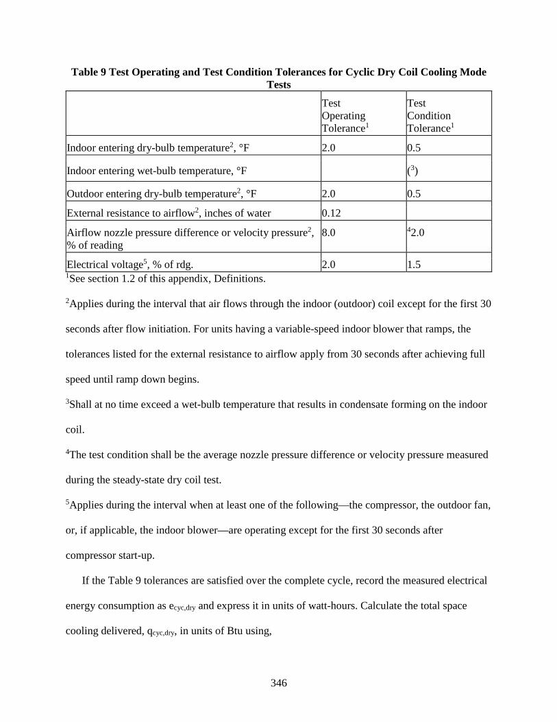
346
Table 9 Test Operating and Test Condition Tolerances for Cyclic Dry Coil Cooling Mode Tests
Test Operating Tolerance1
Test Condition Tolerance1
Indoor entering dry-bulb temperature2, °F 2.0 0.5
Indoor entering wet-bulb temperature, °F (3)
Outdoor entering dry-bulb temperature2, °F 2.0 0.5
External resistance to airflow2, inches of water 0.12
Airflow nozzle pressure difference or velocity pressure2, % of reading
8.0 42.0
Electrical voltage5, % of rdg. 2.0 1.5 1See section 1.2 of this appendix, Definitions.
2Applies during the interval that air flows through the indoor (outdoor) coil except for the first 30
seconds after flow initiation. For units having a variable-speed indoor blower that ramps, the
tolerances listed for the external resistance to airflow apply from 30 seconds after achieving full
speed until ramp down begins.
3Shall at no time exceed a wet-bulb temperature that results in condensate forming on the indoor
coil.
4The test condition shall be the average nozzle pressure difference or velocity pressure measured
during the steady-state dry coil test.
5Applies during the interval when at least one of the following—the compressor, the outdoor fan,
or, if applicable, the indoor blower—are operating except for the first 30 seconds after
compressor start-up.
If the Table 9 tolerances are satisfied over the complete cycle, record the measured electrical
energy consumption as ecyc,dry and express it in units of watt-hours. Calculate the total space
cooling delivered, qcyc,dry, in units of Btu using,

347
𝑞𝑞𝑐𝑐𝑐𝑐𝑐𝑐,𝑑𝑑𝑉𝑉𝑐𝑐 = 60∗�̇�𝑉∗𝐶𝐶𝑝𝑝,𝑎𝑎∗Γ[𝑣𝑣𝑚𝑚′ ∗(1+𝑊𝑊𝑚𝑚)]
= 60∗�̇�𝑉∗𝐶𝐶𝑝𝑝,𝑎𝑎∗Γ𝑣𝑣𝑚𝑚
and Γ = 𝑁𝑁𝐶𝐶𝐷𝐷∗ ∫ [𝑇𝑇𝑉𝑉1(𝜏𝜏) −𝜏𝜏2𝜏𝜏1
𝑇𝑇𝑉𝑉2(𝜏𝜏)]𝛿𝛿𝜏𝜏, ℎ𝑟𝑟 ∗ ℉
Where,
V̅̇, Cp,a, vn′ (or vn), Wn, and FCD* are the values recorded during the section 3.4 dry coil
steady-state test and
Tal(τ) = dry bulb temperature of the air entering the indoor coil at time τ, °F.
Ta2(τ) = dry bulb temperature of the air leaving the indoor coil at time τ, °F.
τ1 = for ducted units, the elapsed time when airflow is initiated through the indoor coil;
for non-ducted units, the elapsed time when the compressor is cycled on, hr.
τ2 = the elapsed time when indoor coil airflow ceases, hr.
Adjust the total space cooling delivered, qcyc,dry, according to calculation method outlined in
section 7.4.3.4.5 of ASHRAE 116-2010 (incorporated by reference, see §430.3).
3.5.1 Procedures when testing ducted systems.
The automatic controls that are normally installed with the test unit must govern the OFF/ON
cycling of the air moving equipment on the indoor side (exhaust fan of the airflow measuring
apparatus and, if installed, the indoor blower of the test unit). For example, for ducted coil-only
systems rated based on using a fan time delay relay, control the indoor coil airflow according to
the rated ON and/or OFF delays provided by the relay. For ducted units having a variable-speed
indoor blower that has been disabled (and possibly removed), start and stop the indoor airflow at
the same instances as if the fan were enabled. For all other ducted coil-only systems, cycle the
indoor coil airflow in unison with the cycling of the compressor. If air damper boxes are used,
close them on the inlet and outlet side during the OFF period. Airflow through the indoor coil
should stop within 3 seconds after the automatic controls of the test unit (act to) de-energize the
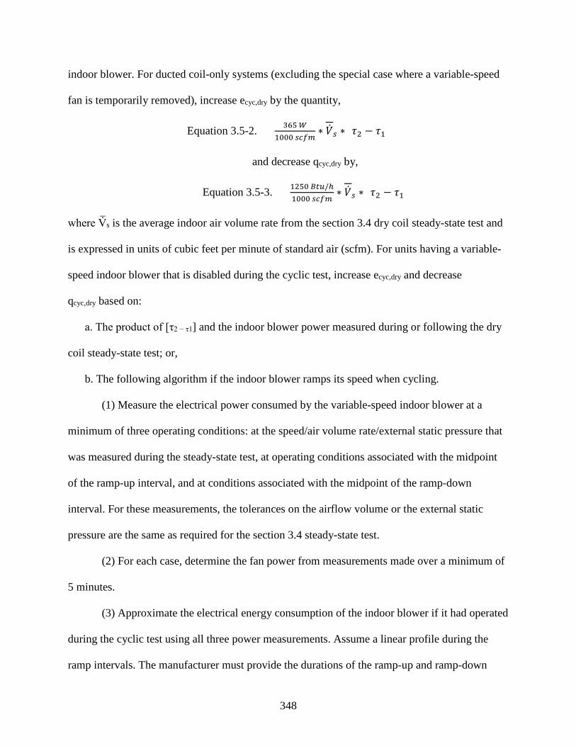
348
indoor blower. For ducted coil-only systems (excluding the special case where a variable-speed
fan is temporarily removed), increase ecyc,dry by the quantity,
Equation 3.5-2. 365 𝑊𝑊1000 𝑠𝑠𝑐𝑐𝑓𝑓𝑚𝑚
∗ �̇�𝑉𝑠𝑠 ∗ [𝜏𝜏2 − 𝜏𝜏1]
and decrease qcyc,dry by,
Equation 3.5-3. 1250 𝐵𝐵𝐵𝐵𝐵𝐵/ℎ1000 𝑠𝑠𝑐𝑐𝑓𝑓𝑚𝑚
∗ �̇�𝑉𝑠𝑠 ∗ [𝜏𝜏2 − 𝜏𝜏1]
where V̅̇s is the average indoor air volume rate from the section 3.4 dry coil steady-state test and
is expressed in units of cubic feet per minute of standard air (scfm). For units having a variable-
speed indoor blower that is disabled during the cyclic test, increase ecyc,dry and decrease
qcyc,dry based on:
a. The product of [τ2 − τ1] and the indoor blower power measured during or following the dry
coil steady-state test; or,
b. The following algorithm if the indoor blower ramps its speed when cycling.
(1) Measure the electrical power consumed by the variable-speed indoor blower at a
minimum of three operating conditions: at the speed/air volume rate/external static pressure that
was measured during the steady-state test, at operating conditions associated with the midpoint
of the ramp-up interval, and at conditions associated with the midpoint of the ramp-down
interval. For these measurements, the tolerances on the airflow volume or the external static
pressure are the same as required for the section 3.4 steady-state test.
(2) For each case, determine the fan power from measurements made over a minimum of
5 minutes.
(3) Approximate the electrical energy consumption of the indoor blower if it had operated
during the cyclic test using all three power measurements. Assume a linear profile during the
ramp intervals. The manufacturer must provide the durations of the ramp-up and ramp-down

349
intervals. If the test setup instructions included with the unit by the manufacturer specifies a
ramp interval that exceeds 45 seconds, use a 45-second ramp interval nonetheless when
estimating the fan energy.
3.5.2 Procedures when testing non-ducted indoor units.
Do not use airflow prevention devices when conducting cyclic tests on non-ducted indoor
units. Until the last OFF/ON compressor cycle, airflow through the indoor coil must cycle off
and on in unison with the compressor. For the last OFF/ON compressor cycle—the one used to
determine ecyc,dry and qcyc,dry—use the exhaust fan of the airflow measuring apparatus and the
indoor blower of the test unit to have indoor airflow start 3 minutes prior to compressor cut-on
and end three minutes after compressor cutoff. Subtract the electrical energy used by the indoor
blower during the 3 minutes prior to compressor cut-on from the integrated electrical energy,
ecyc,dry. Add the electrical energy used by the indoor blower during the 3 minutes after
compressor cutoff to the integrated cooling capacity, qcyc,dry. For the case where the non-ducted
indoor unit uses a variable-speed indoor blower which is disabled during the cyclic test, correct
ecyc,dry and qcyc,dry using the same approach as prescribed in section 3.5.1 of this appendix for
ducted units having a disabled variable-speed indoor blower.
3.5.3 Cooling-mode cyclic-degradation coefficient calculation.
Use the two dry-coil tests to determine the cooling-mode cyclic-degradation coefficient, CDc.
Append “(k=2)” to the coefficient if it corresponds to a two-capacity unit cycling at high
capacity. The default value for two-capacity units cycling at high capacity, however, is the low-
capacity coefficient, i.e., CDc(k=2) = CD
c. Evaluate CDc using the above results and those from
the section 3.4 dry-coil steady-state test.
𝑈𝑈𝐷𝐷𝑐𝑐 =1 − 𝐸𝐸𝐸𝐸𝐸𝐸𝑐𝑐𝑐𝑐𝑐𝑐,𝑑𝑑𝑑𝑑𝑐𝑐
𝐸𝐸𝐸𝐸𝐸𝐸𝑠𝑠𝑠𝑠,𝑑𝑑𝑑𝑑𝑐𝑐
1 − 𝑈𝑈𝑈𝑈𝑁𝑁
350
where:
𝐸𝐸𝐸𝐸𝐸𝐸𝑐𝑐𝑐𝑐𝑐𝑐,𝑑𝑑𝑉𝑉𝑐𝑐 =𝑞𝑞𝑐𝑐𝑐𝑐𝑐𝑐,𝑑𝑑𝑉𝑉𝑐𝑐
𝑆𝑆𝑐𝑐𝑐𝑐𝑐𝑐,𝑑𝑑𝑉𝑉𝑐𝑐
the average energy efficiency ratio during the cyclic dry coil cooling mode test, Btu/W·h
𝐸𝐸𝐸𝐸𝐸𝐸𝑠𝑠𝑠𝑠,𝑑𝑑𝑉𝑉𝑐𝑐 =�̇�𝑄𝑠𝑠𝑠𝑠,𝑑𝑑𝑉𝑉𝑐𝑐
�̇�𝐸𝑠𝑠𝑠𝑠,𝑑𝑑𝑉𝑉𝑐𝑐
the average energy efficiency ratio during the steady-state dry coil cooling mode test,
Btu/W·h
𝑈𝑈𝑈𝑈𝑁𝑁 =𝑞𝑞𝑐𝑐𝑐𝑐𝑐𝑐,𝑑𝑑𝑉𝑉𝑐𝑐
𝑄𝑄𝑠𝑠𝑠𝑠,𝑑𝑑𝑉𝑉𝑐𝑐 ∗ Δ𝜏𝜏𝑐𝑐𝑐𝑐𝑐𝑐,𝑑𝑑𝑉𝑉𝑐𝑐
the cooling load factor dimensionless
Round the calculated value for CDc to the nearest 0.01. If CD
c is negative, then set it equal to
zero.
3.6 Heating mode tests for different types of heat pumps, including heating-only heat pumps.
3.6.1 Tests for a heat pump having a single-speed compressor and fixed heating air volume rate.
This set of tests is for single-speed-compressor heat pumps that do not have a heating
minimum air volume rate or a heating intermediate air volume rate that is different than the
heating full load air volume rate. Conduct the optional high temperature cyclic (H1C) test to
determine the heating mode cyclic-degradation coefficient, CDh. A default value for CD
h may be
used in lieu of conducting the cyclic test. The default value of CDh is 0.25. Test conditions for
the four tests are specified in Table 10.

351
Table 10 Heating Mode Test Conditions for Units Having a Single-Speed Compressor and a Fixed-Speed Indoor Blower, a Constant Air Volume Rate Indoor Blower, or No Indoor
Blower
Test description
Air entering indoor unit Temperature (°F)
Air entering outdoor unit Temperature (°F)
Heating air volume rate
Dry bulb Wet bulb Dry bulb Wet bulb
H1 Test (required, steady)
70 60(max) 47 43 Heating Full-load1
H1C Test (optional, cyclic)
70 60(max) 47 43 (2)
H2 Test (required) 70 60(max) 35 33 Heating Full-load1
H3 Test (required, steady)
70 60(max) 17 15 Heating Full-load1
1Defined in section 3.1.4.4 of this appendix.
2Maintain the airflow nozzles static pressure difference or velocity pressure during the ON
period at the same pressure difference or velocity pressure as measured during the H1 Test.
3.6.2 Tests for a heat pump having a single-speed compressor and a single indoor unit having
either (1) a variable speed, variable-air-rate indoor blower whose capacity modulation correlates
with outdoor dry bulb temperature or (2) multiple indoor blowers. Conduct five tests: two high
temperature tests (H12 and H11), one frost accumulation test (H22), and two low temperature
tests (H32 and H31). Conducting an additional frost accumulation test (H21) is optional. Conduct
the optional high temperature cyclic (H1C1) test to determine the heating mode cyclic-
degradation coefficient, CDh. A default value for CD
h may be used in lieu of conducting the
cyclic. The default value of CDh is 0.25. Test conditions for the seven tests are specified in Table
11. If the optional H21 test is not performed, use the following equations to approximate the
capacity and electrical power of the heat pump at the H21 test conditions:
�̇�𝑄ℎ𝑘𝑘=1(35) = 𝑄𝑄𝐸𝐸ℎ𝑘𝑘=2(35) ∗ ��̇�𝑄ℎ𝑘𝑘=1(17) + 0.6 ∗ ��̇�𝑄ℎ𝑘𝑘=1(47) − �̇�𝑄ℎ𝑘𝑘=1(17)��

352
�̇�𝐸ℎ𝑘𝑘=1(35) = 𝑃𝑃𝐸𝐸ℎ𝑘𝑘=2(35) ∗ ��̇�𝐸ℎ𝑘𝑘=1(17) + 0.6 ∗ ��̇�𝐸ℎ𝑘𝑘=1(47) − �̇�𝐸ℎ𝑘𝑘=1(17)��
where:
�̇�𝑄𝐸𝐸ℎ𝑘𝑘=2(35) = �̇�𝑄ℎ𝑘𝑘=2(35)
�̇�𝑄𝑘𝑘=2(17) + 0.6 ∗ [�̇�𝑄ℎ𝑘𝑘=2(47) − �̇�𝑄ℎ𝑘𝑘=2(17)]
𝑃𝑃𝐸𝐸ℎ𝑘𝑘=2(35) =�̇�𝐸ℎ𝑘𝑘=2(35)
�̇�𝐸ℎ𝑘𝑘=2(17) + 0.6 ∗ ��̇�𝐸ℎ𝑘𝑘=2(47) − �̇�𝐸ℎ𝑘𝑘=2(17)�
The quantities Q̇hk=2(47), Ėh
k=2(47), Q̇hk=1(47), and Ėh
k=1(47) are determined from the H12 and
H11 tests and evaluated as specified in section 3.7 of this appendix; the quantities Q̇hk=2(35)
and Ėhk=2(35) are determined from the H22 test and evaluated as specified in section 3.9 of
this appendix; and the quantities Q̇hk=2(17), Ėh
k=2(17), Q̇hk=1(17), and Ėh
k=1(17), are
determined from the H32 and H31 tests and evaluated as specified in section 3.10 of this
appendix.
Table 11 Heating Mode Test Conditions for Units with a Single-Speed Compressor That Meet the Section 3.6.2 Indoor Unit Requirements
Test description
Air entering indoor unit temperature (°F)
Air entering outdoor unit temperature (°F)
Heating air volume rate
Dry bulb Wet bulb Dry bulb Wet bulb
H12 Test (required, steady)
70 60(max) 47 43 Heating Full-load.1
H11 Test (required, steady)
70 60(max) 47 43 Heating Minimum.2
H1C1 Test (optional, cyclic)
70 60(max) 47 43 (3)
H22 Test (required) 70 60(max) 35 33 Heating Full-load.1
H21 Test (optional) 70 60(max) 35 33 Heating Minimum.2
H32 Test (required, steady)
70 60(max) 17 15 Heating Full-load.1

353
H31 Test (required, steady)
70 60(max) 17 15 Heating Minimum.2
1Defined in section 3.1.4.4 of this appendix.
2Defined in section 3.1.4.5 of this appendix.
3Maintain the airflow nozzles static pressure difference or velocity pressure during the ON period at the same
pressure difference or velocity pressure as measured during the H11 test.
3.6.3 Tests for a heat pump having a two-capacity compressor (see section 1.2 of this appendix,
Definitions), including two-capacity, northern heat pumps (see section 1.2 of this appendix,
Definitions).
a. Conduct one maximum temperature test (H01), two high temperature tests (H12and H11),
one frost accumulation test (H22), and one low temperature test (H32). Conduct an additional
frost accumulation test (H21) and low temperature test (H31) if both of the following conditions
exist:
(1) Knowledge of the heat pump's capacity and electrical power at low compressor
capacity for outdoor temperatures of 37 °F and less is needed to complete the section 4.2.3 of
this appendix seasonal performance calculations; and
(2) The heat pump's controls allow low-capacity operation at outdoor temperatures of 37
°F and less.
If the above two conditions are met, an alternative to conducting the H21 frost accumulation
is to use the following equations to approximate the capacity and electrical power:
�̇�𝑄ℎ𝑘𝑘=1(35) = 0.90 ∗ ��̇�𝑄ℎ𝑘𝑘=1(17) + 0.6 ∗ ��̇�𝑄ℎ𝑘𝑘=1(47) − �̇�𝑄ℎ𝑘𝑘=1(17)��
�̇�𝐸ℎ𝑘𝑘=1(35) = 0.985 ∗ ��̇�𝐸ℎ𝑘𝑘=1(17) + 0.6 ∗ ��̇�𝐸ℎ𝑘𝑘=1(47) − �̇�𝐸ℎ𝑘𝑘=1(17)��
Determine the quantities Q̇hk=1 (47) and Ėh
k=1 (47) from the H11 test and evaluate them
according to section 3.7 of this appendix. Determine the quantities Q̇hk=1 (17) and Ėh
k=1 (17) from
the H31 test and evaluate them according to section 3.10 of this appendix.

354
b. Conduct the optional high temperature cyclic test (H1C1) to determine the heating mode
cyclic-degradation coefficient, CDh. A default value for CD
h may be used in lieu of conducting
the cyclic. The default value of CDh is 0.25. If a two-capacity heat pump locks out low capacity
operation at lower outdoor temperatures, conduct the high temperature cyclic test (H1C2) to
determine the high-capacity heating mode cyclic-degradation coefficient, CDh (k=2). The default
CDh (k=2) is the same value as determined or assigned for the low-capacity cyclic-degradation
coefficient, CDh [or equivalently, CD
h (k=1)]. Table 12 specifies test conditions for these nine
tests.
Table 12 Heating Mode Test Conditions for Units Having a Two-Capacity Compressor Test description
Air entering indoor unit temperature (°F)
Air entering outdoor unit temperature (°F)
Compressor capacity
Heating air volume rate
Dry bulb Wet bulb Dry bulb
Wet bulb
H01 Test (required, steady)
70 60(max) 62 56.5 Low Heating Minimum.1
H12 Test (required, steady)
70 60(max) 47 43 High Heating Full-Load.2
H1C2 Test (optional7, cyclic)
70 60(max) 47 43 High (3)
H11 Test (required)
70 60(max) 47 43 Low Heating Minimum.1
H1C1 Test (optional, cyclic)
70 60(max) 47 43 Low (4)
H22 Test (required)
70 60(max) 35 33 High Heating Full-Load.2
H21 Test5 6 (required)
70 60(max) 35 33 Low Heating Minimum.1
H32 Test (required, steady)
70 60(max) 17 15 High Heating Full-Load.2

355
H31 Test5 (required, steady)
70 60(max) 17 15 Low Heating Minimum.1
1Defined in section 3.1.4.5 of this appendix.
2Defined in section 3.1.4.4 of this appendix.
3Maintain the airflow nozzle(s) static pressure difference or velocity pressure during the ON period at the same
pressure or velocity as measured during the H12 test.
4Maintain the airflow nozzle(s) static pressure difference or velocity pressure during the ON period at the same
pressure or velocity as measured during the H11 test.
5Required only if the heat pump's performance when operating at low compressor capacity and outdoor temperatures
less than 37 °F is needed to complete the section 4.2.3 HSPF calculations.
6If table note #5 applies, the section 3.6.3 equations for Q̇hk=1 (35) and Ėh
k=1 (17) may be used in lieu of conducting
the H21 test.
7Required only if the heat pump locks out low capacity operation at lower outdoor temperatures.
3.6.4 Tests for a heat pump having a variable-speed compressor.
a. Conduct one maximum temperature test (H01), two high temperature tests (H12 and H11),
one frost accumulation test (H2V), and one low temperature test (H32). Conducting one or both of
the following tests is optional: An additional high temperature test (H1N) and an additional frost
accumulation test (H22). Conduct the optional maximum temperature cyclic (H0C1) test to
determine the heating mode cyclic-degradation coefficient, CDh. A default value for CD
h may be
used in lieu of conducting the cyclic. The default value of CDh is 0.25. Test conditions for the
eight tests are specified in Table 13. The compressor shall operate at the same heating full
speed, measured by RPM or power input frequency (Hz), for the H12, H22, and H32 tests. The
compressor shall operate at the same heating minimum speed, measured by RPM or power input
frequency (Hz), for the H01, H0C1, and H11 tests. Determine the heating intermediate
compressor speed cited in Table 13 using the heating mode full and minimum compressors
speeds and:

356
Heating intermediate speed
= Heating minimum speed + Heating full speed − Heating minimum speed
3
Where a tolerance of plus 5 percent or the next higher inverter frequency step from that
calculated is allowed.
If the H22 test is not done, use the following equations to approximate the capacity and
electrical power at the H22 test conditions:
�̇�𝑄ℎ𝑘𝑘=2(35) = 0.90 ∗ ��̇�𝑄ℎ𝑘𝑘=2(17) + 0.6 ∗ ��̇�𝑄ℎ𝑘𝑘=2(47) − �̇�𝑄ℎ𝑘𝑘=2(17)��
�̇�𝐸ℎ𝑘𝑘=2(35) = 0.985 ∗ ��̇�𝐸ℎ𝑘𝑘=2(17) + 0.6 ∗ ��̇�𝐸ℎ𝑘𝑘=2(47) − �̇�𝐸ℎ𝑘𝑘=2(17)��
b. Determine the quantities Q̇hk=2(47) and from Ėh
k=2(47) from the H12 test and evaluate them
according to section 3.7 of this appendix. Determine the quantities Q̇hk=2(17) and Ėh
k=2(17) from
the H32 test and evaluate them according to section 3.10 of this appendix. For heat pumps where
the heating mode full compressor speed exceeds its cooling mode full compressor speed, conduct
the H1N test if the manufacturer requests it. If the H1N test is done, operate the heat pump's
compressor at the same speed as the speed used for the cooling mode A2 test. Refer to the last
sentence of section 4.2 of this appendix to see how the results of the H1N test may be used in
calculating the heating seasonal performance factor.
Table 13 Heating Mode Test Conditions for Units Having a Variable-Speed Compressor
Test description
Air entering indoor unit temperature (°F)
Air entering outdoor unit temperature (°F)
Compressor speed
Heating air volume rate
Dry bulb Wet bulb Dry bulb
Wet
bulb
H01 test (required, steady)
70 60(max) 62 56.5 Heating Minimum
Heating Minimum.1

357
H0C1 test (optional, cyclic)
70 60(max) 62 56.5 Heating Minimum
(2)
H12 test (required, steady)
70 60(max) 47 43 Heating Full Heating Full-Load.3
H11 test (required, steady)
70 60(max) 47 43 Heating Minimum
Heating Minimum.1
H1N test (optional, steady)
70 60(max) 47 43 Cooling Full Heating Nominal.4
H22 test (optional)
70 60(max) 35 33 Heating Full Heating Full-Load.3
H2V test (required)
70 60(max) 35 33 Heating Intermediate
Heating Intermediate.5
H32 test (required, steady)
70 60(max) 17 15 Heating Full Heating Full-Load.3
1Defined in section 3.1.4.5 of this appendix.
2Maintain the airflow nozzle(s) static pressure difference or velocity pressure during an ON period at the same
pressure or velocity as measured during the H01 test.
3Defined in section 3.1.4.4 of this appendix.
4Defined in section 3.1.4.7 of this appendix.
5Defined in section 3.1.4.6 of this appendix.
c. For multiple-split heat pumps (only), the following procedures supersede the above
requirements. For all Table 13 tests specified for a minimum compressor speed, at least one
indoor unit must be turned off. The manufacturer shall designate the particular indoor unit(s) that
is turned off. The manufacturer must also specify the compressor speed used for the Table 13
H2V test, a heating mode intermediate compressor speed that falls within 1⁄4 and 3⁄4 of the
difference between the full and minimum heating mode speeds. The manufacturer should
prescribe an intermediate speed that is expected to yield the highest COP for the given H2V test
conditions and bracketed compressor speed range. The manufacturer can designate that one or
more specific indoor units are turned off for the H2V test.
3.6.5 Additional test for a heat pump having a heat comfort controller.
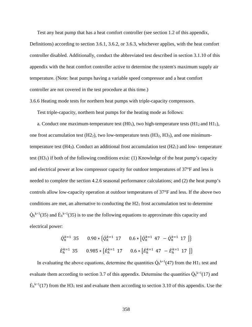
358
Test any heat pump that has a heat comfort controller (see section 1.2 of this appendix,
Definitions) according to section 3.6.1, 3.6.2, or 3.6.3, whichever applies, with the heat comfort
controller disabled. Additionally, conduct the abbreviated test described in section 3.1.10 of this
appendix with the heat comfort controller active to determine the system's maximum supply air
temperature. (Note: heat pumps having a variable speed compressor and a heat comfort
controller are not covered in the test procedure at this time.)
3.6.6 Heating mode tests for northern heat pumps with triple-capacity compressors.
Test triple-capacity, northern heat pumps for the heating mode as follows:
a. Conduct one maximum-temperature test (H01), two high-temperature tests (H12 and H11),
one frost accumulation test (H22), two low-temperature tests (H32, H33), and one minimum-
temperature test (H43). Conduct an additional frost accumulation test (H21) and low- temperature
test (H31) if both of the following conditions exist: (1) Knowledge of the heat pump’s capacity
and electrical power at low compressor capacity for outdoor temperatures of 37°F and less is
needed to complete the section 4.2.6 seasonal performance calculations; and (2) the heat pump’s
controls allow low-capacity operation at outdoor temperatures of 37°F and less. If the above two
conditions are met, an alternative to conducting the H21 frost accumulation test to determine
Q̇hk=1(35) and Ėh
k=1(35) is to use the following equations to approximate this capacity and
electrical power:
�̇�𝑄ℎ𝑘𝑘=1(35) = 0.90 ∗ ��̇�𝑄ℎ𝑘𝑘=1(17) + 0.6 ∗ ��̇�𝑄ℎ𝑘𝑘=1(47) − �̇�𝑄ℎ𝑘𝑘=1(17)��
�̇�𝐸ℎ𝑘𝑘=1(35) = 0.985 ∗ ��̇�𝐸ℎ𝑘𝑘=1(17) + 0.6 ∗ ��̇�𝐸ℎ𝑘𝑘=1(47) − �̇�𝐸ℎ𝑘𝑘=1(17)��
In evaluating the above equations, determine the quantities Q̇hk=1(47) from the H11 test and
evaluate them according to section 3.7 of this appendix. Determine the quantities Q̇hk=1(17) and
Ėhk=1(17) from the H31 test and evaluate them according to section 3.10 of this appendix. Use the

359
paired values of Q̇hk=1(35) and Ėh
k=1(35) derived from conducting the H21 frost accumulation test
and evaluated as specified in section 3.9.1 of this appendix or use the paired values calculated
using the above default equations, whichever contribute to a higher Region IV HSPF based on
the DHRmin.
b. Conducting a frost accumulation test (H23) with the heat pump operating at its booster
capacity is optional. If this optional test is not conducted, determine Q̇hk=3(35) and Ėh
k=3(35)
using the following equations to approximate this capacity and electrical power:
�̇�𝑄ℎ𝑘𝑘=3(35) = 𝑄𝑄𝐸𝐸ℎ𝑘𝑘=2(35) ∗ ��̇�𝑄ℎ𝑘𝑘=3(17) + 1.20 ∗ ��̇�𝑄ℎ𝑘𝑘=3(17) − �̇�𝑄ℎ𝑘𝑘=3(2)��
�̇�𝐸ℎ𝑘𝑘=3(35) = 𝑃𝑃𝐸𝐸ℎ𝑘𝑘=2(35) ∗ ��̇�𝐸ℎ𝑘𝑘=3(17) + 1.20 ∗ ��̇�𝐸ℎ𝑘𝑘=3(17) − �̇�𝐸ℎ𝑘𝑘=3(2)��
Where:
𝑄𝑄𝐸𝐸ℎ𝑘𝑘=2(35) =�̇�𝑄ℎ𝑘𝑘=2(35)
�̇�𝑄ℎ𝑘𝑘=2(17) + 0.6 ∗ ��̇�𝑄ℎ𝑘𝑘=2(47) − �̇�𝑄ℎ𝑘𝑘=2(17)�
𝑃𝑃𝐸𝐸ℎ𝑘𝑘=2(35) =�̇�𝐸ℎ𝑘𝑘=2(35)
�̇�𝐸ℎ𝑘𝑘=2(17) + 0.6 ∗ ��̇�𝐸ℎ𝑘𝑘=2(47) − �̇�𝐸ℎ𝑘𝑘=2(17)�
Determine the quantities Q̇hk=2(47) and Ėh
k=2(47) from the H12 test and evaluate them
according to section 3.7 of this appendix. Determine the quantities Q̇hk=2(35) and Ėh
k=2(35) from
the H22 test and evaluate them according to section 3.9.1 of this appendix. Determine the
quantities Q̇hk=2(17) and Ėh
k=2(17) from the H32 test, determine the quantities Q̇hk=3(17) and
Ėhk=3(17) from the H33 test, and determine the quantities Q̇h
k=3(2) and Ėhk=3(2) from the H43 test.
Evaluate all six quantities according to section 3.10 of this appendix. Use the paired values of
Q̇hk=3(35) and Ėh
k=3(35) derived from conducting the H23 frost accumulation test and calculated
as specified in section 3.9.1 of this appendix or use the paired values calculated using the above

360
default equations, whichever contribute to a higher Region IV HSPF based on the DHRmin.
c. Conduct the optional high-temperature cyclic test (H1C1) to determine the heating mode
cyclic-degradation coefficient, CDh. A default value for CD
h may be used in lieu of conducting
the cyclic. The default value of CDh is 0.25. If a triple-capacity heat pump locks out low capacity
operation at lower outdoor temperatures, conduct the high-temperature cyclic test (H1C2) to
determine the high-capacity heating mode cyclic-degradation coefficient, CDh (k=2). The default
CDh (k=2) is the same value as determined or assigned for the low-capacity cyclic-degradation
coefficient, CDh [or equivalently, CD
h (k=1)]. Finally, if a triple-capacity heat pump locks out
both low and high capacity operation at the lowest outdoor temperatures, conduct the low-
temperature cyclic test (H3C3) to determine the booster-capacity heating mode cyclic-
degradation coefficient, CDh (k=3). The default CD
h (k=3) is the same value as determined or
assigned for the high-capacity cyclic-degradation coefficient, CDh [or equivalently, CD
h (k=2)].
Table 14 specifies test conditions for all 13 tests.
Table 14 Heating Mode Test Conditions for Units with a Triple-Capacity Compressor
Test description Air entering indoor unit temperature
°F
Air entering outdoor unit temperature
°F
Compressor capacity
Heating air volume rate
Dry bulb Wet
bulb
Dry bulb Wet bulb
H01 Test (required, steady) 70 60(max) 62 56.5 Low Heating Minimum1
H12 Test (required, steady) 70 60(max) 47 43 High Heating Full-Load2
H1C2 Test (optional8, cyclic) 70 60(max) 47 43 High 3
H11 Test (required) 70 60(max) 47 43 Low Heating Minimum1
H1C1 Test (optional, cyclic) 70 60(max) 47 43 Low 4
H23 Test (optional, steady) 70 60(max) 35 33 Booster Heating Full-Load2
H22 Test (required) 70 60(max) 35 33 High Heating Full-Load2
H21 Test (required) 70 60(max) 35 33 Low Heating Minimum1
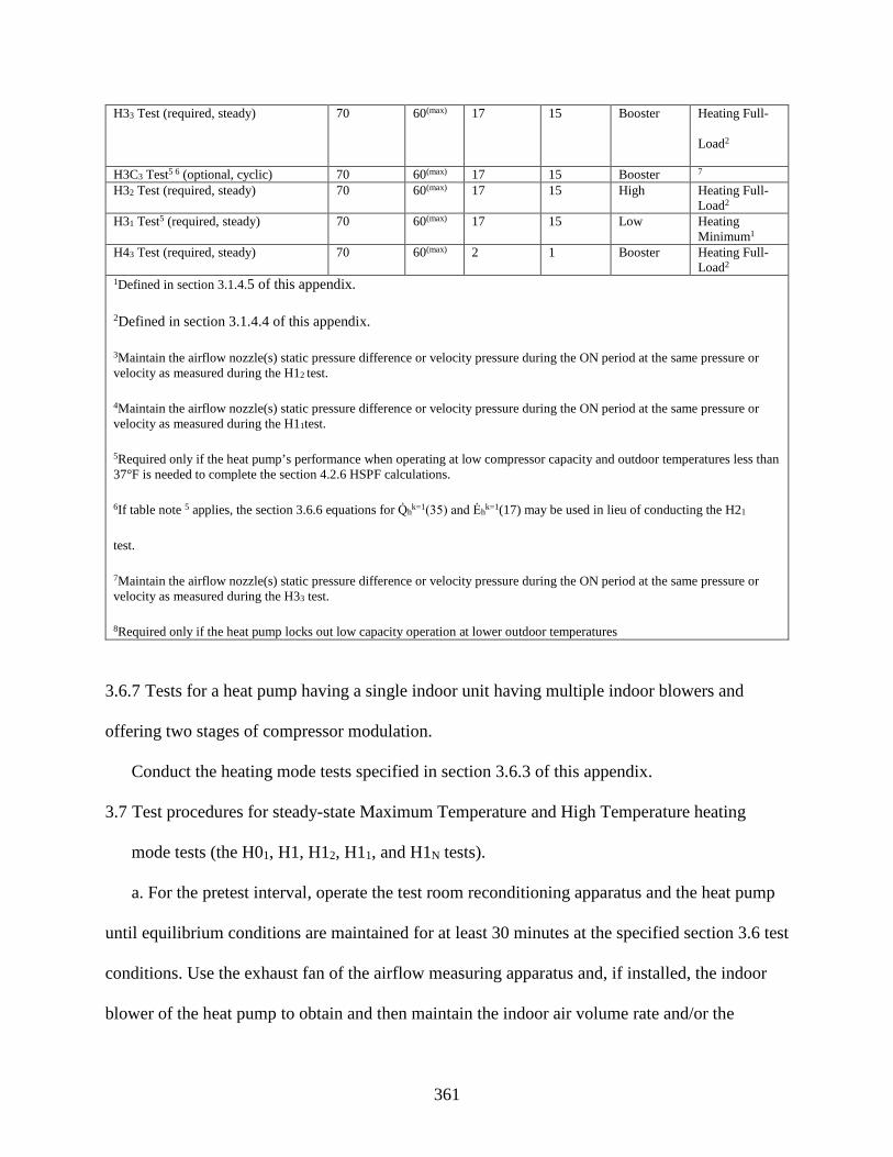
361
H33 Test (required, steady) 70 60(max) 17 15 Booster Heating Full-
Load2
H3C3 Test5 6 (optional, cyclic) 70 60(max) 17 15 Booster 7
H32 Test (required, steady) 70 60(max) 17 15 High Heating Full-Load2
H31 Test5 (required, steady) 70 60(max) 17 15 Low Heating Minimum1
H43 Test (required, steady) 70 60(max) 2 1 Booster Heating Full-Load2
1Defined in section 3.1.4.5 of this appendix.
2Defined in section 3.1.4.4 of this appendix.
3Maintain the airflow nozzle(s) static pressure difference or velocity pressure during the ON period at the same pressure or velocity as measured during the H12 test.
4Maintain the airflow nozzle(s) static pressure difference or velocity pressure during the ON period at the same pressure or velocity as measured during the H11test.
5Required only if the heat pump’s performance when operating at low compressor capacity and outdoor temperatures less than 37°F is needed to complete the section 4.2.6 HSPF calculations.
6If table note 5 applies, the section 3.6.6 equations for Q̇hk=1(35) and Ėhk=1(17) may be used in lieu of conducting the H21
test.
7Maintain the airflow nozzle(s) static pressure difference or velocity pressure during the ON period at the same pressure or velocity as measured during the H33 test.
8Required only if the heat pump locks out low capacity operation at lower outdoor temperatures
3.6.7 Tests for a heat pump having a single indoor unit having multiple indoor blowers and
offering two stages of compressor modulation.
Conduct the heating mode tests specified in section 3.6.3 of this appendix.
3.7 Test procedures for steady-state Maximum Temperature and High Temperature heating
mode tests (the H01, H1, H12, H11, and H1N tests).
a. For the pretest interval, operate the test room reconditioning apparatus and the heat pump
until equilibrium conditions are maintained for at least 30 minutes at the specified section 3.6 test
conditions. Use the exhaust fan of the airflow measuring apparatus and, if installed, the indoor
blower of the heat pump to obtain and then maintain the indoor air volume rate and/or the

362
external static pressure specified for the particular test. Continuously record the dry-bulb
temperature of the air entering the indoor coil, and the dry-bulb temperature and water vapor
content of the air entering the outdoor coil. Refer to section 3.11 of this appendix for additional
requirements that depend on the selected secondary test method. After satisfying the pretest
equilibrium requirements, make the measurements specified in Table 3 of ANSI/ASHRAE 37-
2009 (incorporated by reference, see §430.3) for the indoor air enthalpy method and the user-
selected secondary method. Make said Table 3 measurements at equal intervals that span 5
minutes or less. Continue data sampling until a 30-minute period (e.g., seven consecutive 5-
minute samples) is reached where the test tolerances specified in Table 15 are satisfied. For those
continuously recorded parameters, use the entire data set for the 30-minute interval when
evaluating Table 15 compliance. Determine the average electrical power consumption of the heat
pump over the same 30-minute interval.
Table 15 Test Operating and Test Condition Tolerances for Section 3.7 and Section 3.10 Steady-State Heating Mode Tests
Test operating tolerance1
Test condition tolerance1
Indoor dry-bulb, °F:
Entering temperature 2.0 0.5
Leaving temperature 2.0
Indoor wet-bulb, °F:
Entering temperature 1.0
Leaving temperature 1.0
Outdoor dry-bulb, °F:
Entering temperature 2.0 0.5
Leaving temperature 22.0
Outdoor wet-bulb, °F:
Entering temperature 1.0 0.3

363
Leaving temperature 21.0
External resistance to airflow, inches of water 0.12 30.02
Electrical voltage, % of rdg 2.0 1.5
Nozzle pressure drop, % of rdg 8.0 1See section 1.2 of this appendix, Definitions.
2Only applies when the Outdoor Air Enthalpy Method is used.
3Only applies when testing non-ducted units.
b. Calculate indoor-side total heating capacity as specified in sections 7.3.4.1 and 7.3.4.3 of
ANSI/ASHRAE 37-2009 (incorporated by reference, see §430.3). To calculate capacity, use the
averages of the measurements (e.g. inlet and outlet dry bulb temperatures measured at the
psychrometers) that are continuously recorded for the same 30-minute interval used as described
above to evaluate compliance with test tolerances. Do not adjust the parameters used in
calculating capacity for the permitted variations in test conditions. Assign the average space
heating capacity and electrical power over the 30-minute data collection interval to the variables
Q̇hk and Ėh
k(T) respectively. The “T” and superscripted “k” are the same as described in section
3.3 of this appendix. Additionally, for the heating mode, use the superscript to denote results
from the optional H1N test, if conducted.
c. For coil-only system heat pumps, increase Q̇hk(T) by
1250𝐵𝐵𝑇𝑇𝑈𝑈 ℎ⁄1000 𝑠𝑠𝑠𝑠𝑓𝑓𝑠𝑠
∗ �̇�𝑉𝑠𝑠�
and increase Ėhk(T) by,
365 𝑊𝑊1000 𝑠𝑠𝑠𝑠𝑓𝑓𝑠𝑠
∗ �̇�𝑉𝑠𝑠�
where V̅̇s is the average measured indoor air volume rate expressed in units of cubic feet per
minute of standard air (scfm). During the 30-minute data collection interval of a high
temperature test, pay attention to preventing a defrost cycle. Prior to this time, allow the heat

364
pump to perform a defrost cycle if automatically initiated by its own controls. As in all cases,
wait for the heat pump's defrost controls to automatically terminate the defrost cycle. Heat
pumps that undergo a defrost should operate in the heating mode for at least 10 minutes after
defrost termination prior to beginning the 30-minute data collection interval. For some heat
pumps, frost may accumulate on the outdoor coil during a high temperature test. If the indoor
coil leaving air temperature or the difference between the leaving and entering air temperatures
decreases by more than 1.5 °F over the 30-minute data collection interval, then do not use the
collected data to determine capacity. Instead, initiate a defrost cycle. Begin collecting data no
sooner than 10 minutes after defrost termination. Collect 30 minutes of new data during which
the Table 15 test tolerances are satisfied. In this case, use only the results from the second 30-
minute data collection interval to evaluate Q̇hk(47) and Ėh
k(47).
d. If conducting the cyclic heating mode test, which is described in section 3.8 of this
appendix, record the average indoor-side air volume rate, V̅̇, specific heat of the air,
Cp,a (expressed on dry air basis), specific volume of the air at the nozzles, vn′ (or vn), humidity
ratio at the nozzles, Wn, and either pressure difference or velocity pressure for the flow nozzles.
If either or both of the below criteria apply, determine the average, steady-state, electrical power
consumption of the indoor blower motor (Ėfan,1):
(1) The section 3.8 cyclic test will be conducted and the heat pump has a variable-speed
indoor blower that is expected to be disabled during the cyclic test; or
(2) The heat pump has a (variable-speed) constant-air volume-rate indoor blower and
during the steady-state test the average external static pressure (ΔP1) exceeds the applicable
section 3.1.4.4 minimum (or targeted) external static pressure (ΔPmin) by 0.03 inches of water or
more.

365
Determine Ėfan,1 by making measurements during the 30-minute data collection interval, or
immediately following the test and prior to changing the test conditions. When the above “2”
criteria applies, conduct the following four steps after determining Ėfan,1 (which corresponds to
ΔP1):
(i) While maintaining the same test conditions, adjust the exhaust fan of the airflow
measuring apparatus until the external static pressure increases to approximately ΔP1 + (ΔP1 −
ΔPmin).
(ii) After re-establishing steady readings for fan motor power and external static
pressure, determine average values for the indoor blower power (Ėfan,2) and the external static
pressure (ΔP2) by making measurements over a 5-minute interval.
(iii) Approximate the average power consumption of the indoor blower motor if the
30-minute test had been conducted at ΔPmin using linear extrapolation:
�̇�𝐸𝑓𝑓𝑉𝑉𝑛𝑛,min =�̇�𝐸𝑓𝑓𝑉𝑉𝑛𝑛,2 − �̇�𝐸𝑓𝑓𝑉𝑉𝑛𝑛,1
Δ𝑃𝑃2 − Δ𝑃𝑃1(Δ𝑃𝑃min − Δ𝑃𝑃1) + �̇�𝐸𝑓𝑓𝑉𝑉𝑛𝑛,1
(iv) Decrease the total space heating capacity, Q̇hk(T), by the quantity (Ėfan,1 −
Ėfan,min), when expressed on a Btu/h basis. Decrease the total electrical power, Ėhk(T) by the same
fan power difference, now expressed in watts.
e. If the temperature sensors used to provide the primary measurement of the indoor-side dry
bulb temperature difference during the steady-state dry-coil test and the subsequent cyclic dry-
coil test are different, include measurements of the latter sensors among the regularly sampled
data. Beginning at the start of the 30-minute data collection period, measure and compute the
indoor-side air dry-bulb temperature difference using both sets of instrumentation, ΔT (Set SS)
and ΔT (Set CYC), for each equally spaced data sample. If using a consistent data sampling rate
that is less than 1 minute, calculate and record minutely averages for the two temperature

366
differences. If using a consistent sampling rate of one minute or more, calculate and record the
two temperature differences from each data sample. After having recorded the seventh (i=7) set
of temperature differences, calculate the following ratio using the first seven sets of values:
𝑁𝑁𝐶𝐶𝐷𝐷 =17�
Δ𝑇𝑇(𝑁𝑁𝑆𝑆𝑡𝑡 𝑁𝑁𝑁𝑁)Δ𝑇𝑇(𝑁𝑁𝑆𝑆𝑡𝑡 𝑈𝑈𝐶𝐶𝑈𝑈)
𝑖𝑖
𝑖𝑖−6
Each time a subsequent set of temperature differences is recorded (if sampling more frequently
than every 5 minutes), calculate FCD using the most recent seven sets of values. Continue these
calculations until the 30-minute period is completed or until a value for FCD is calculated that
falls outside the allowable range of 0.94–1.06. If the latter occurs, immediately suspend the test
and identify the cause for the disparity in the two temperature difference measurements.
Recalibration of one or both sets of instrumentation may be required. If all the values for FCD are
within the allowable range, save the final value of the ratio from the 30-minute test as FCD*. If
the temperature sensors used to provide the primary measurement of the indoor-side dry bulb
temperature difference during the steady-state dry-coil test and the subsequent cyclic dry-coil test
are the same, set FCD*= 1.
3.8 Test procedures for the cyclic heating mode tests (the H0C1, H1C, H1C1 and H1C2 tests).
a. Except as noted below, conduct the cyclic heating mode test as specified in section 3.5 of
this appendix. As adapted to the heating mode, replace section 3.5 references to “the steady-state
dry coil test” with “the heating mode steady-state test conducted at the same test conditions as
the cyclic heating mode test.” Use the test tolerances in Table 16 rather than Table 9. Record the
outdoor coil entering wet-bulb temperature according to the requirements given in section 3.5 of
this appendix for the outdoor coil entering dry-bulb temperature. Drop the subscript “dry” used
in variables cited in section 3.5 of this appendix when referring to quantities from the cyclic

367
heating mode test. , The default CD value for heating is 0.25. If available, use electric resistance
heaters (see section 2.1 of this appendix) to minimize the variation in the inlet air temperature.
Determine the total space heating delivered during the cyclic heating test, qcyc, as specified in
section 3.5 of this appendix except for making the following changes:
(1) When evaluating Equation 3.5-1, use the values of V̅̇, Cp,a,vn′, (or vn), and Wn that
were recorded during the section 3.7 steady-state test conducted at the same test conditions.
(2) Calculate Γ using, Γ = 𝑁𝑁𝐶𝐶𝐷𝐷∗ ∫ [𝑇𝑇𝑉𝑉1(𝜏𝜏) − 𝑇𝑇𝑉𝑉2(𝜏𝜏)]𝛿𝛿𝜏𝜏,𝜏𝜏2𝜏𝜏1
ℎ𝑟𝑟 × ∘ 𝑁𝑁,
where FCD* is the value recorded during the section 3.7 steady-state test conducted at the
same test condition.
b. For ducted coil-only system heat pumps (excluding the special case where a variable-speed
fan is temporarily removed), increase qcyc by the amount calculated using Equation 3.5-3.
Additionally, increase ecyc by the amount calculated using Equation 3.5-2. In making these
calculations, use the average indoor air volume rate (V̅̇s) determined from the section 3.7 steady-
state heating mode test conducted at the same test conditions.
c. For non-ducted heat pumps, subtract the electrical energy used by the indoor blower during
the 3 minutes after compressor cutoff from the non-ducted heat pump's integrated heating
capacity, qcyc.
d. If a heat pump defrost cycle is manually or automatically initiated immediately prior to or
during the OFF/ON cycling, operate the heat pump continuously until 10 minutes after defrost
termination. After that, begin cycling the heat pump immediately or delay until the specified test
conditions have been re-established. Pay attention to preventing defrosts after beginning the
cycling process. For heat pumps that cycle off the indoor blower during a defrost cycle, make no
effort here to restrict the air movement through the indoor coil while the fan is off. Resume the

368
OFF/ON cycling while conducting a minimum of two complete compressor OFF/ON cycles
before determining qcyc and ecyc.
3.8.1 Heating mode cyclic-degradation coefficient calculation.
Use the results from the required cyclic test and the required steady-state test that were
conducted at the same test conditions to determine the heating mode cyclic-degradation
coefficient CDh. Add “(k=2)” to the coefficient if it corresponds to a two-capacity unit cycling at
high capacity. For the below calculation of the heating mode cyclic degradation coefficient, do
not include the duct loss correction from section 7.3.3.3 of ANSI/ASHRAE 37-2009
(incorporated by reference, see §430.3) in determining Q̇hk(Tcyc) (or qcyc). The default value for
two-capacity units cycling at high capacity, however, is the low-capacity coefficient, i.e.,
CDh (k=2) = CD
h. The tested CDh is calculated as follows:
𝑈𝑈𝐷𝐷ℎ =1 − 𝐶𝐶𝐶𝐶𝑃𝑃𝑐𝑐𝑐𝑐𝑐𝑐
𝐶𝐶𝐶𝐶𝑃𝑃𝑠𝑠𝑠𝑠�𝑇𝑇𝑐𝑐𝑐𝑐𝑐𝑐�
1 − 𝐻𝐻𝑈𝑈𝑁𝑁
where:
𝑈𝑈𝐶𝐶𝑃𝑃𝑐𝑐𝑐𝑐𝑐𝑐 =𝑞𝑞𝑐𝑐𝑐𝑐𝑐𝑐
3.413 𝐵𝐵𝐵𝐵𝐵𝐵 ℎ⁄𝑊𝑊
∗ 𝑆𝑆𝑐𝑐𝑐𝑐𝑐𝑐
the average coefficient of performance during the cyclic heating mode test,
dimensionless.
𝑈𝑈𝐶𝐶𝑃𝑃𝑠𝑠𝑠𝑠(𝑇𝑇𝑐𝑐𝑐𝑐𝑐𝑐) =�̇�𝑄ℎ𝑘𝑘�𝑇𝑇𝑐𝑐𝑐𝑐𝑐𝑐�
3.413 𝐵𝐵𝐵𝐵𝐵𝐵 ℎ⁄𝑊𝑊
∗ �̇�𝐸ℎ𝑘𝑘�𝑇𝑇𝑐𝑐𝑐𝑐𝑐𝑐�
the average coefficient of performance during the steady-state heating mode test
conducted at the same test conditions—i.e., same outdoor dry bulb temperature, Tcyc, and

369
speed/capacity, k, if applicable—as specified for the cyclic heating mode test,
dimensionless.
𝐻𝐻𝑈𝑈𝑁𝑁 =𝑞𝑞𝑐𝑐𝑐𝑐𝑐𝑐
�̇�𝑄ℎ𝑘𝑘�𝑇𝑇𝑐𝑐𝑐𝑐𝑐𝑐� ∗ Δ𝜏𝜏𝑐𝑐𝑐𝑐𝑐𝑐
the heating load factor, dimensionless.
Tcyc = the nominal outdoor temperature at which the cyclic heating mode test is
conducted, 62 or 47 °F.
Δτcyc = the duration of the OFF/ON intervals; 0.5 hours when testing a heat pump having
a single-speed or two-capacity compressor and 1.0 hour when testing a heat pump having
a variable-speed compressor.
Round the calculated value for CDh to the nearest 0.01. If CD
h is negative, then set it equal to
zero.

370
Table 16 Test operating and test condition tolerances for cyclic heating mode tests.
Test operating tolerance1
Test condition tolerance1
Indoor entering dry-bulb temperature,2 °F 2.0 0.5
Indoor entering wet-bulb temperature,2 °F 1.0
Outdoor entering dry-bulb temperature,2 °F 2.0 0.5
Outdoor entering wet-bulb temperature,2 °F 2.0 1.0
External resistance to air-flow,2 inches of water 0.12
Airflow nozzle pressure difference or velocity pressure,2 % of reading
2.0 32.0
Electrical voltage,4 % of rdg 8.0 1.5 1See section 1.2 of this appendix, Definitions.
2Applies during the interval that air flows through the indoor (outdoor) coil except for the first 30 seconds after flow
initiation. For units having a variable-speed indoor blower that ramps, the tolerances listed for the external resistance
to airflow shall apply from 30 seconds after achieving full speed until ramp down begins.
3The test condition shall be the average nozzle pressure difference or velocity pressure measured during the steady-
state test conducted at the same test conditions.
4Applies during the interval that at least one of the following—the compressor, the outdoor fan, or, if applicable, the
indoor blower—are operating, except for the first 30 seconds after compressor start-up.
3.9 Test procedures for frost accumulation heating mode tests (the H2, H22, H2V, and H21 tests).
a. Confirm that the defrost controls of the heat pump are set as specified in section 2.2.1 of
this appendix. Operate the test room reconditioning apparatus and the heat pump for at least 30
minutes at the specified section 3.6 test conditions before starting the “preliminary” test period.
The preliminary test period must immediately precede the “official” test period, which is the
heating and defrost interval over which data are collected for evaluating average space heating
capacity and average electrical power consumption.
b. For heat pumps containing defrost controls which are likely to cause defrosts at intervals
less than one hour, the preliminary test period starts at the termination of an automatic defrost

371
cycle and ends at the termination of the next occurring automatic defrost cycle. For heat pumps
containing defrost controls which are likely to cause defrosts at intervals exceeding one hour, the
preliminary test period must consist of a heating interval lasting at least one hour followed by a
defrost cycle that is either manually or automatically initiated. In all cases, the heat pump's own
controls must govern when a defrost cycle terminates.
c. The official test period begins when the preliminary test period ends, at defrost
termination. The official test period ends at the termination of the next occurring automatic
defrost cycle. When testing a heat pump that uses a time-adaptive defrost control system (see
section 1.2 of this appendix, Definitions), however, manually initiate the defrost cycle that ends
the official test period at the instant indicated by instructions provided by the manufacturer. If the
heat pump has not undergone a defrost after 6 hours, immediately conclude the test and use the
results from the full 6-hour period to calculate the average space heating capacity and average
electrical power consumption.
For heat pumps that turn the indoor blower off during the defrost cycle, take steps to cease
forced airflow through the indoor coil and block the outlet duct whenever the heat pump's
controls cycle off the indoor blower. If it is installed, use the outlet damper box described in
section 2.5.4.1 of this appendix to affect the blocked outlet duct.
d. Defrost termination occurs when the controls of the heat pump actuate the first change in
converting from defrost operation to normal heating operation. Defrost initiation occurs when the
controls of the heat pump first alter its normal heating operation in order to eliminate possible
accumulations of frost on the outdoor coil.
e. To constitute a valid frost accumulation test, satisfy the test tolerances specified in Table
17 during both the preliminary and official test periods. As noted in Table 17, test operating

372
tolerances are specified for two sub-intervals: (1) When heating, except for the first 10 minutes
after the termination of a defrost cycle (sub-interval H, as described in Table 17) and (2) when
defrosting, plus these same first 10 minutes after defrost termination (sub-interval D, as
described in Table 17). Evaluate compliance with Table 17 test condition tolerances and the
majority of the test operating tolerances using the averages from measurements recorded only
during sub-interval H. Continuously record the dry bulb temperature of the air entering the
indoor coil, and the dry bulb temperature and water vapor content of the air entering the outdoor
coil. Sample the remaining parameters listed in Table 17 at equal intervals that span 5 minutes or
less.
f. For the official test period, collect and use the following data to calculate average space
heating capacity and electrical power. During heating and defrosting intervals when the controls
of the heat pump have the indoor blower on, continuously record the dry-bulb temperature of the
air entering (as noted above) and leaving the indoor coil. If using a thermopile, continuously
record the difference between the leaving and entering dry-bulb temperatures during the
interval(s) that air flows through the indoor coil. For coil-only system heat pumps, determine the
corresponding cumulative time (in hours) of indoor coil airflow, Δτa. Sample measurements used
in calculating the air volume rate (refer to sections 7.7.2.1 and 7.7.2.2 of ANSI/ASHRAE 37-
2009) at equal intervals that span 10 minutes or less. (Note: In the first printing of
ANSI/ASHRAE 37-2009, the second IP equation for Qmi should read:) Record the electrical
energy consumed, expressed in watt-hours, from defrost termination to defrost termination,
eDEFk(35), as well as the corresponding elapsed time in hours, ΔτFR.
Table 17 Test Operating and Test Condition Tolerances for Frost Accumulation Heating Mode Tests.
Test operating tolerance1

373
Sub-interval H2 Sub-interval D3 Test condition tolerance1 Sub-interval H2
Indoor entering dry-bulb temperature, °F 2.0 44.0 0.5
Indoor entering wet-bulb temperature, °F 1.0
Outdoor entering dry-bulb temperature, °F 2.0 10.0 1.0
Outdoor entering wet-bulb temperature, °F 1.5 0.5
External resistance to airflow, inches of water 0.12 0.025
Electrical voltage, % of rdg 2.0 1.5 1See section 1.2 of this appendix, Definitions.
2Applies when the heat pump is in the heating mode, except for the first 10 minutes after termination of a defrost
cycle.
3Applies during a defrost cycle and during the first 10 minutes after the termination of a defrost cycle when the heat
pump is operating in the heating mode.
4For heat pumps that turn off the indoor blower during the defrost cycle, the noted tolerance only applies during the
10 minute interval that follows defrost termination.
5Only applies when testing non-ducted heat pumps.
3.9.1 Average space heating capacity and electrical power calculations.
a. Evaluate average space heating capacity, Q̇hk(35), when expressed in units of Btu per hour,
using:
�̇�𝑄ℎ𝑘𝑘(35) =60 ∗ �̇�𝑉� ∗ 𝑈𝑈𝑝𝑝,𝑉𝑉 ∗ Γ
Δ𝜏𝜏𝐹𝐹𝐸𝐸[𝜈𝜈𝑛𝑛′ ∗ (1 + 𝑊𝑊𝑛𝑛)] =60 ∗ �̇�𝑉� ∗ 𝑈𝑈𝑝𝑝,𝑉𝑉 ∗ Γ
Δ𝜏𝜏𝐹𝐹𝐸𝐸𝜈𝜈𝑛𝑛
where,
V̅̇ = the average indoor air volume rate measured during sub-interval H, cfm.
Cp,a = 0.24 + 0.444 · Wn, the constant pressure specific heat of the air-water vapor
mixture that flows through the indoor coil and is expressed on a dry air basis, Btu /
lbmda · °F.
vn′ = specific volume of the air-water vapor mixture at the nozzle, ft3 / lbmmx.

374
Wn = humidity ratio of the air-water vapor mixture at the nozzle, lbm of water vapor per
lbm of dry air.
ΔτFR = τ2 − τ1, the elapsed time from defrost termination to defrost termination, hr.
Γ = ∫ [𝑇𝑇𝑉𝑉2(𝜏𝜏) − 𝑇𝑇𝑉𝑉1𝜏𝜏2𝜏𝜏1
(𝜏𝜏)]𝑑𝑑𝜏𝜏, ℎ𝑟𝑟 ∗ ∘𝑁𝑁
Tal(τ) = dry bulb temperature of the air entering the indoor coil at elapsed time τ, °F; only
recorded when indoor coil airflow occurs; assigned the value of zero during periods (if
any) where the indoor blower cycles off.
Ta2(τ) = dry bulb temperature of the air leaving the indoor coil at elapsed time τ, °F; only
recorded when indoor coil airflow occurs; assigned the value of zero during periods (if
any) where the indoor blower cycles off.
τ1 = the elapsed time when the defrost termination occurs that begins the official test
period, hr.
τ2 = the elapsed time when the next automatically occurring defrost termination occurs,
thus ending the official test period, hr.
vn = specific volume of the dry air portion of the mixture evaluated at the dry-bulb
temperature, vapor content, and barometric pressure existing at the nozzle, ft3 per lbm of
dry air.
To account for the effect of duct losses between the outlet of the indoor unit and the section
2.5.4 dry-bulb temperature grid, adjust Q̇hk(35) in accordance with section 7.3.4.3 of
ANSI/ASHRAE 37-2009 (incorporated by reference, see §430.3).
b. Evaluate average electrical power, Ėhk(35), when expressed in units of watts, using:
�̇�𝐸ℎ𝑘𝑘(35) =𝑆𝑆𝑑𝑑𝑑𝑑𝑓𝑓(35)Δ𝜏𝜏𝐹𝐹𝐸𝐸
For coil-only system heat pumps, increase Q̇hk(35) by,

375
1250𝐵𝐵𝑡𝑡𝐵𝐵 ℎ⁄1000 𝑠𝑠𝑠𝑠𝑓𝑓𝑠𝑠
∗ �̇�𝑉𝑠𝑠� ∗Δ𝜏𝜏𝑉𝑉Δ𝜏𝜏𝐹𝐹𝐸𝐸
and increase Ėhk(35) by,
365 𝑊𝑊1000 𝑠𝑠𝑠𝑠𝑓𝑓𝑠𝑠
∗ �̇�𝑉𝑠𝑠� ∗Δ𝜏𝜏𝑉𝑉Δ𝜏𝜏𝐹𝐹𝐸𝐸
where V̅̇s is the average indoor air volume rate measured during the frost accumulation
heating mode test and is expressed in units of cubic feet per minute of standard air (scfm).
c. For heat pumps having a constant-air-volume-rate indoor blower, the five additional steps
listed below are required if the average of the external static pressures measured during sub-
interval H exceeds the applicable section 3.1.4.4, 3.1.4.5, or 3.1.4.6 minimum (or targeted)
external static pressure (ΔPmin) by 0.03 inches of water or more:
(1) Measure the average power consumption of the indoor blower motor (Ėfan,1) and
record the corresponding external static pressure (ΔP1) during or immediately following the frost
accumulation heating mode test. Make the measurement at a time when the heat pump is heating,
except for the first 10 minutes after the termination of a defrost cycle.
(2) After the frost accumulation heating mode test is completed and while maintaining
the same test conditions, adjust the exhaust fan of the airflow measuring apparatus until the
external static pressure increases to approximately ΔP1 + (ΔP1 − ΔPmin).
(3) After re-establishing steady readings for the fan motor power and external static
pressure, determine average values for the indoor blower power (Ėfan,2) and the external static
pressure (ΔP2) by making measurements over a 5-minute interval.

376
(4) Approximate the average power consumption of the indoor blower motor had the
frost accumulation heating mode test been conducted at ΔPmin using linear extrapolation:
�̇�𝐸𝑓𝑓𝑉𝑉𝑛𝑛,min =�̇�𝐸𝑓𝑓𝑉𝑉𝑛𝑛,2 − �̇�𝐸𝑓𝑓𝑉𝑉𝑛𝑛,1
Δ𝑃𝑃2 − Δ𝑃𝑃1(Δ𝑃𝑃min − Δ𝑃𝑃1) + �̇�𝐸𝑓𝑓𝑉𝑉𝑛𝑛,1
(5) Decrease the total heating capacity, Q̇hk(35), by the quantity [(Ėfan,1 − Ėfan,min)·
(Δτ a/Δτ FR], when expressed on a Btu/h basis. Decrease the total electrical power, Ehk(35), by the
same quantity, now expressed in watts.
3.9.2 Demand defrost credit.
a. Assign the demand defrost credit, Fdef, that is used in section 4.2 of this appendix to the
value of 1 in all cases except for heat pumps having a demand-defrost control system (see section
1.2 of this appendix, Definitions). For such qualifying heat pumps, evaluate Fdef using,
𝑁𝑁𝑑𝑑𝑑𝑑𝑓𝑓 = 1 + 0.03 ∗ �1 −Δ𝜏𝜏𝑑𝑑𝑑𝑑𝑓𝑓 − 1.5Δ𝜏𝜏max − 1.5
�
where:
Δτdef = the time between defrost terminations (in hours) or 1.5, whichever is greater. A
value of 6 must be assigned to Δτdef if this limit is reached during a frost accumulation
test and the heat pump has not completed a defrost cycle.
Δτmax = maximum time between defrosts as allowed by the controls (in hours) or 12,
whichever is less, as provided in the certification report.
b. For two-capacity heat pumps and for section 3.6.2 units, evaluate the above equation using
the Δτdef that applies based on the frost accumulation test conducted at high capacity and/or at the
heating full-load air volume rate. For variable-speed heat pumps, evaluate Δτdef based on the
required frost accumulation test conducted at the intermediate compressor speed.

377
3.10 Test procedures for steady-state low temperature heating mode tests (the H3, H32, and
H31 tests).
Except for the modifications noted in this section, conduct the low temperature heating mode
test using the same approach as specified in section 3.7 of this appendix for the maximum and
high temperature tests. After satisfying the section 3.7 requirements for the pretest interval but
before beginning to collect data to determine Q̇hk(17) and Ėh
k(17), conduct a defrost cycle. This
defrost cycle may be manually or automatically initiated. The defrost sequence must be
terminated by the action of the heat pump's defrost controls. Begin the 30-minute data collection
interval described in section 3.7 of this appendix, from which Q̇hk(17) and Ėh
k(17) are
determined, no sooner than 10 minutes after defrost termination. Defrosts should be prevented
over the 30-minute data collection interval.
3.11 Additional requirements for the secondary test methods.
3.11.1 If using the outdoor air enthalpy method as the secondary test method.
During the “official” test, the outdoor air-side test apparatus described in section 2.10.1 of
this appendix is connected to the outdoor unit. To help compensate for any effect that the
addition of this test apparatus may have on the unit's performance, conduct a “preliminary” test
where the outdoor air-side test apparatus is disconnected. Conduct a preliminary test prior to the
first section 3.2 of this appendix steady-state cooling mode test and prior to the first section 3.6
of this appendix steady-state heating mode test. No other preliminary tests are required so long as
the unit operates the outdoor fan during all cooling mode steady-state tests at the same speed and
all heating mode steady-state tests at the same speed. If using more than one outdoor fan speed
for the cooling mode steady-state tests, however, conduct a preliminary test prior to each cooling

378
mode test where a different fan speed is first used. This same requirement applies for the heating
mode tests.
3.11.1.1 Preliminary test.
3.11.1.1.1 If a preliminary test precedes the official test.
a. The test conditions for the preliminary test are the same as specified for the official test.
Connect the indoor air-side test apparatus to the indoor coil; disconnect the outdoor air-side test
apparatus. Allow the test room reconditioning apparatus and the unit being tested to operate for
at least one hour. After attaining equilibrium conditions, measure the following quantities at
equal intervals that span 5 minutes or less:
(1) The section 2.10.1 of this appendix evaporator and condenser temperatures or
pressures;
(2) Parameters required according to the indoor air enthalpy method.
Continue these measurements until a 30-minute period (e.g., seven consecutive 5-minute
samples) is obtained where the Table 8 or Table 15, whichever applies, test tolerances are
satisfied.
b. After collecting 30 minutes of steady-state data, reconnect the outdoor air-side test
apparatus to the unit. Adjust the exhaust fan of the outdoor airflow measuring apparatus until
averages for the evaporator and condenser temperatures, or the saturated temperatures
corresponding to the measured pressures, agree within ±0.5 °F of the averages achieved when the
outdoor air-side test apparatus was disconnected. Calculate the averages for the reconnected case
using five or more consecutive readings taken at one minute intervals. Make these consecutive
readings after re-establishing equilibrium conditions and before initiating the official
test.3.11.1.1.2 If a preliminary test does not precede the official test.

379
Connect the outdoor-side test apparatus to the unit. Adjust the exhaust fan of the outdoor
airflow measuring apparatus to achieve the same external static pressure as measured during the
prior preliminary test conducted with the unit operating in the same cooling or heating mode at
the same outdoor fan speed.
3.11.1.1 Official test.
a. Continue (preliminary test was conducted) or begin (no preliminary test) the official test
by making measurements for both the indoor and outdoor air enthalpy methods at equal intervals
that span 5 minutes or less. Discontinue these measurements only after obtaining a 30-minute
period where the specified test condition and test operating tolerances are satisfied. To constitute
a valid official test:
(1) Achieve the energy balance specified in section 3.1.1 of this appendix; and,
(2) For cases where a preliminary test is conducted, the capacities determined using the
indoor air enthalpy method from the official and preliminary test periods must agree within 2.0
percent.
b. For space cooling tests, calculate capacity from the outdoor air-enthalpy measurements as
specified in sections 7.3.3.2 and 7.3.3.3 of ANSI/ASHRAE 37-2009 (incorporated by reference,
see §430.3). Calculate heating capacity based on outdoor air-enthalpy measurements as specified
in sections 7.3.4.2 and 7.3.3.4.3 of the same ASHRAE Standard. Adjust the outdoor-side
capacity according to section 7.3.3.4 of ANSI/ASHRAE 37-2009 to account for line losses when
testing split systems. Use the outdoor unit fan power as measured during the official test and not
the value measured during the preliminary test, as described in section 8.6.2 of ANSI/ASHRAE
37-2009, when calculating the capacity.
3.11.2 If using the compressor calibration method as the secondary test method.

380
a. Conduct separate calibration tests using a calorimeter to determine the refrigerant flow
rate. Or for cases where the superheat of the refrigerant leaving the evaporator is less than 5 °F,
use the calorimeter to measure total capacity rather than refrigerant flow rate. Conduct these
calibration tests at the same test conditions as specified for the tests in this appendix. Operate the
unit for at least one hour or until obtaining equilibrium conditions before collecting data that will
be used in determining the average refrigerant flow rate or total capacity. Sample the data at
equal intervals that span 5 minutes or less. Determine average flow rate or average capacity from
data sampled over a 30-minute period where the Table 8 (cooling) or the Table 15 (heating)
tolerances are satisfied. Otherwise, conduct the calibration tests according to sections 5, 6, 7, and
8 of ASHRAE 23.1-2010 (incorporated by reference, see §430.3); sections 5, 6, 7, 8, 9, and 11 of
ASHRAE 41.9-2011 (incorporated by reference, see §430.3); and section 7.4 of ANSI/ASHRAE
37-2009 (incorporated by reference, see §430.3).
b. Calculate space cooling and space heating capacities using the compressor calibration
method measurements as specified in section 7.4.5 and 7.4.6 respectively, of ANSI/ASHRAE
37-2009.
3.11.3 If using the refrigerant-enthalpy method as the secondary test method.
Conduct this secondary method according to section 7.5 of ANSI/ASHRAE 37-2009.
Calculate space cooling and heating capacities using the refrigerant-enthalpy method
measurements as specified in sections 7.5.4 and 7.5.5, respectively, of the same ASHRAE
Standard.
3.12 Rounding of space conditioning capacities for reporting purposes.
a. When reporting rated capacities, round them off as specified in §430.23 (for a single unit)
and in 10 CFR 429.16 (for a sample).

381
b. For the capacities used to perform the calculations in section 4 of this appendix, however,
round only to the nearest integer.
3.13 Laboratory testing to determine off mode average power ratings.
Voltage tolerances: as a percentage of reading, test operating tolerance shall be 2.0 percent
and test condition tolerance shall be 1.5 percent (see section 1.2 of this appendix for definitions
of these tolerances).
Conduct one of the following tests: if the central air conditioner or heat pump lacks a
compressor crankcase heater, perform the test in section 3.13.1 of this appendix; if the central air
conditioner or heat pump has a compressor crankcase heater that lacks controls and is not self-
regulating, perform the test in section 3.13.1 of this appendix; if the central air conditioner or
heat pump has a crankcase heater with a fixed power input controlled with a thermostat that
measures ambient temperature and whose sensing element temperature is not affected by the
heater, perform the test in section 3.13.1 of this appendix; if the central air conditioner or heat
pump has a compressor crankcase heater equipped with self-regulating control or with controls
for which the sensing element temperature is affected by the heater, perform the test in section
3.13.2 of this appendix.
3.13.1 This test determines the off mode average power rating for central air conditioners and
heat pumps that lack a compressor crankcase heater, or have a compressor crankcase heating
system that can be tested without control of ambient temperature during the test. This test has
no ambient condition requirements.
a. Test Sample Set-up and Power Measurement: For coil-only systems, provide a furnace or
modular blower that is compatible with the system to serve as an interface with the thermostat (if
used for the test) and to provide low-voltage control circuit power. Make all control circuit

382
connections between the furnace (or modular blower) and the outdoor unit as specified by the
manufacturer’s installation instructions. Measure power supplied to both the furnace or modular
blower and power supplied to the outdoor unit. Alternatively, provide a compatible transformer
to supply low-voltage control circuit power, as described in section 2.2.d of this appendix.
Measure transformer power, either supplied to the primary winding or supplied by the secondary
winding of the transformer, and power supplied to the outdoor unit. For blower coil and single-
package systems, make all control circuit connections between components as specified by the
manufacturer’s installation instructions, and provide power and measure power supplied to all
system components.
b. Configure Controls: Configure the controls of the central air conditioner or heat pump so
that it operates as if connected to a building thermostat that is set to the OFF position. Use a
compatible building thermostat if necessary to achieve this configuration. For a thermostat-
controlled crankcase heater with a fixed power input, bypass the crankcase heater thermostat if
necessary to energize the heater.
c. Measure 𝑃𝑃2𝑚𝑚: If the unit has a crankcase heater time delay, make sure that time delay
function is disabled or wait until delay time has passed. Determine the average power from non-
zero value data measured over a 5-minute interval of the non-operating central air conditioner or
heat pump and designate the average power as 𝑃𝑃2𝑚𝑚, the heating season total off mode power.
d. Measure 𝑃𝑃𝑚𝑚 for coil-only split systems and for blower coil split systems for which a
furnace or a modular blower is the designated air mover: Disconnect all low-voltage wiring for
the outdoor components and outdoor controls from the low-voltage transformer. Determine the
average power from non-zero value data measured over a 5-minute interval of the power
supplied to the (remaining) low-voltage components of the central air conditioner or heat pump,

383
or low-voltage power, 𝑃𝑃𝑚𝑚. This power measurement does not include line power supplied to the
outdoor unit. It is the line power supplied to the air mover, or, if a compatible transformer is
used instead of an air mover, it is the line power supplied to the transformer primary coil. If a
compatible transformer is used instead of an air mover and power output of the low-voltage
secondary circuit is measured, Px is zero.
e. Calculate P2: Set the number of compressors equal to the unit’s number of single-stage
compressors plus 1.75 times the unit’s number of compressors that are not single-stage.
For single-package systems and blower coil split systems for which the designated air mover
is not a furnace or modular blower, divide the heating season total off mode power (𝑃𝑃2𝑚𝑚) by the
number of compressors to calculate P2, the heating season per-compressor off mode power.
Round P2 to the nearest watt. The expression for calculating P2 is as follows:
𝑃𝑃2 = 𝑃𝑃2𝑥𝑥𝑛𝑛𝐵𝐵𝑚𝑚𝑛𝑛𝑑𝑑𝑉𝑉 𝑜𝑜𝑓𝑓 𝑐𝑐𝑜𝑜𝑚𝑚𝑝𝑝𝑉𝑉𝑑𝑑𝑠𝑠𝑠𝑠𝑜𝑜𝑉𝑉𝑠𝑠
.
For coil-only split systems and blower coil split systems for which a furnace or a modular
blower is the designated air mover, subtract the low-voltage power (𝑃𝑃𝑚𝑚) from the heating season
total off mode power (𝑃𝑃2𝑚𝑚) and divide by the number of compressors to calculate P2, the heating
season per-compressor off mode power. Round P2 to the nearest watt. The expression for
calculating P2 is as follows:
𝑃𝑃2 = 𝑃𝑃2𝑥𝑥−𝑃𝑃𝑥𝑥𝑛𝑛𝐵𝐵𝑚𝑚𝑛𝑛𝑑𝑑𝑉𝑉 𝑜𝑜𝑓𝑓 𝑐𝑐𝑜𝑜𝑚𝑚𝑝𝑝𝑉𝑉𝑑𝑑𝑠𝑠𝑠𝑠𝑜𝑜𝑉𝑉𝑠𝑠
.
f. Shoulder-season per-compressor off mode power, P1: If the system does not have a
crankcase heater, has a crankcase heater without controls that is not self-regulating, or has a
value for the crankcase heater turn-on temperature (as certified in the DOE Compliance
Certification Database) that is higher than 71 ˚F, P1 is equal to P2.

384
Otherwise, de-energize the crankcase heater (by removing the thermostat bypass or otherwise
disconnecting only the power supply to the crankcase heater) and repeat the measurement as
described in section 3.13.1.c of this appendix. Designate the measured average power as 𝑃𝑃1𝑚𝑚,
the shoulder season total off mode power.
Determine the number of compressors as described in section 3.13.1.e of this appendix.
For single-package systems and blower coil systems for which the designated air mover is
not a furnace or modular blower, divide the shoulder season total off mode power (𝑃𝑃1𝑚𝑚) by the
number of compressors to calculate P1, the shoulder season per-compressor off mode power.
Round P1 to the nearest watt. The expression for calculating P1 is as follows:
𝑃𝑃1 = 𝑃𝑃1𝑥𝑥𝑛𝑛𝐵𝐵𝑚𝑚𝑛𝑛𝑑𝑑𝑉𝑉 𝑜𝑜𝑓𝑓 𝑐𝑐𝑜𝑜𝑚𝑚𝑝𝑝𝑉𝑉𝑑𝑑𝑠𝑠𝑠𝑠𝑜𝑜𝑉𝑉𝑠𝑠
.
For coil-only split systems and blower coil split systems for which a furnace or a modular
blower is the designated air mover, subtract the low-voltage power (𝑃𝑃𝑚𝑚) from the shoulder season
total off mode power (𝑃𝑃1𝑚𝑚) and divide by the number of compressors to calculate P1, the
shoulder season per-compressor off mode power. Round P1 to the nearest watt. The expression
for calculating P1 is as follows:
𝑃𝑃1 = 𝑃𝑃1𝑥𝑥−𝑃𝑃𝑥𝑥𝑛𝑛𝐵𝐵𝑚𝑚𝑛𝑛𝑑𝑑𝑉𝑉 𝑜𝑜𝑓𝑓 𝑐𝑐𝑜𝑜𝑚𝑚𝑝𝑝𝑉𝑉𝑑𝑑𝑠𝑠𝑠𝑠𝑜𝑜𝑉𝑉𝑠𝑠
.
3.13.2 This test determines the off mode average power rating for central air conditioners and
heat pumps for which ambient temperature can affect the measurement of crankcase heater
power.
a. Test Sample Set-up and Power Measurement: set up the test and measurement as described
in section 3.13.1.a of this appendix.
b. Configure Controls: Position a temperature sensor to measure the outdoor dry-bulb
temperature in the air between 2 and 6 inches from the crankcase heater control temperature

385
sensor or, if no such temperature sensor exists, position it in the air between 2 and 6 inches from
the crankcase heater. Utilize the temperature measurements from this sensor for this portion of
the test procedure. Configure the controls of the central air conditioner or heat pump so that it
operates as if connected to a building thermostat that is set to the OFF position. Use a
compatible building thermostat if necessary to achieve this configuration.
Conduct the test after completion of the B, B1, or B2 test. Alternatively, start the test when
the outdoor dry-bulb temperature is at 82°F and the temperature of the compressor shell (or
temperature of each compressor’s shell if there is more than one compressor) is at least 81°F.
Then adjust the outdoor temperature at a rate of change of no more than 20 °F per hour and
achieve an outdoor dry-bulb temperature of 72 °F. Maintain this temperature within +/-2 °F
while making the power measurement, as described in section 3.13.2.c of this appendix.
c. Measure 𝑃𝑃1𝑚𝑚: If the unit has a crankcase heater time delay, make sure that time delay
function is disabled or wait until delay time has passed. Determine the average power from non-
zero value data measured over a 5-minute interval of the non-operating central air conditioner or
heat pump and designate the average power as 𝑃𝑃1𝑚𝑚, the shoulder season total off mode power.
For units with crankcase heaters which operate during this part of the test and whose controls
cycle or vary crankcase heater power over time, the test period shall consist of three complete
crankcase heater cycles or 18 hours, whichever comes first. Designate the average power over
the test period as 𝑃𝑃1𝑚𝑚, the shoulder season total off mode power.
d. Reduce outdoor temperature: Approach the target outdoor dry-bulb temperature by
adjusting the outdoor temperature at a rate of change of no more than 20 °F per hour. This target
temperature is five degrees Fahrenheit less than the temperature specified by the manufacturer in
the DOE Compliance Certification Database at which the crankcase heater turns on. Maintain the

386
target temperature within +/-2 °F while making the power measurement, as described in section
3.13.2.e of this appendix.
e. Measure 𝑃𝑃2𝑚𝑚: If the unit has a crankcase heater time delay, make sure that time delay
function is disabled or wait until delay time has passed. Determine the average non-zero power
of the non-operating central air conditioner or heat pump over a 5-minute interval and designate
it as 𝑃𝑃2𝑚𝑚, the heating season total off mode power. For units with crankcase heaters whose
controls cycle or vary crankcase heater power over time, the test period shall consist of three
complete crankcase heater cycles or 18 hours, whichever comes first. Designate the average
power over the test period as 𝑃𝑃2𝑚𝑚, the heating season total off mode power.
f. Measure 𝑃𝑃𝑚𝑚 for coil-only split systems and for blower coil split systems for which a
furnace or modular blower is the designated air mover: Disconnect all low-voltage wiring for the
outdoor components and outdoor controls from the low-voltage transformer. Determine the
average power from non-zero value data measured over a 5-minute interval of the power
supplied to the (remaining) low-voltage components of the central air conditioner or heat pump,
or low-voltage power, 𝑃𝑃𝑚𝑚. This power measurement does not include line power supplied to the
outdoor unit. It is the line power supplied to the air mover, or, if a compatible transformer is
used instead of an air mover, it is the line power supplied to the transformer primary coil. If a
compatible transformer is used instead of an air mover and power output of the low-voltage
secondary circuit is measured, Px is zero.
g. Calculate P1:
Set the number of compressors equal to the unit’s number of single-stage compressors plus
1.75 times the unit’s number of compressors that are not single-stage.

387
For single-package systems and blower coil split systems for which the air mover is not a
furnace or modular blower, divide the shoulder season total off mode power (𝑃𝑃1𝑚𝑚) by the
number of compressors to calculate P1, the shoulder season per-compressor off mode power.
Round to the nearest watt. The expression for calculating P1 is as follows:
𝑃𝑃1 = 𝑃𝑃1𝑥𝑥𝑛𝑛𝐵𝐵𝑚𝑚𝑛𝑛𝑑𝑑𝑉𝑉 𝑜𝑜𝑓𝑓 𝑐𝑐𝑜𝑜𝑚𝑚𝑝𝑝𝑉𝑉𝑑𝑑𝑠𝑠𝑠𝑠𝑜𝑜𝑉𝑉𝑠𝑠
.
For coil-only split systems and blower coil split systems for which a furnace or a modular
blower is the designated air mover, subtract the low-voltage power (𝑃𝑃𝑚𝑚) from the shoulder season
total off mode power (𝑃𝑃1𝑚𝑚) and divide by the number of compressors to calculate P1, the
shoulder season per-compressor off mode power. Round to the nearest watt. The expression for
calculating P1 is as follows:
𝑃𝑃1 = 𝑃𝑃1𝑥𝑥−𝑃𝑃𝑥𝑥𝑛𝑛𝐵𝐵𝑚𝑚𝑛𝑛𝑑𝑑𝑉𝑉 𝑜𝑜𝑓𝑓 𝑐𝑐𝑜𝑜𝑚𝑚𝑝𝑝𝑉𝑉𝑑𝑑𝑠𝑠𝑠𝑠𝑜𝑜𝑉𝑉𝑠𝑠
.
h. Calculate P2:
Determine the number of compressors as described in section 3.13.2.g of this appendix.
For single-package systems and blower coil split systems for which the air mover is not a
furnace, divide the heating season total off mode power (𝑃𝑃2𝑚𝑚) by the number of compressors to
calculate P2, the heating season per-compressor off mode power. Round to the nearest watt. The
expression for calculating P2 is as follows:
𝑃𝑃2 = 𝑃𝑃2𝑥𝑥𝑛𝑛𝐵𝐵𝑚𝑚𝑛𝑛𝑑𝑑𝑉𝑉 𝑜𝑜𝑓𝑓 𝑐𝑐𝑜𝑜𝑚𝑚𝑝𝑝𝑉𝑉𝑑𝑑𝑠𝑠𝑠𝑠𝑜𝑜𝑉𝑉𝑠𝑠
.
For coil-only split systems and blower coil split systems for which a furnace or a modular
blower is the designated air mover, subtract the low-voltage power (𝑃𝑃𝑚𝑚) from the heating season
total off mode power (𝑃𝑃2𝑚𝑚) and divide by the number of compressors to calculate P2, the heating

388
season per-compressor off mode power. Round to the nearest watt. The expression for
calculating P2 is as follows:
𝑃𝑃2 = 𝑃𝑃2𝑥𝑥−𝑃𝑃𝑥𝑥𝑛𝑛𝐵𝐵𝑚𝑚𝑛𝑛𝑑𝑑𝑉𝑉 𝑜𝑜𝑓𝑓 𝑐𝑐𝑜𝑜𝑚𝑚𝑝𝑝𝑉𝑉𝑑𝑑𝑠𝑠𝑠𝑠𝑜𝑜𝑉𝑉𝑠𝑠
.
4. Calculations of Seasonal Performance Descriptors
4.1 Seasonal Energy Efficiency Ratio (SEER) Calculations. SEER must be calculated as follows:
For equipment covered under sections 4.1.2, 4.1.3, and 4.1.4 of this appendix, evaluate the
seasonal energy efficiency ratio,
Equation 4.1-1 𝑁𝑁𝐸𝐸𝐸𝐸𝐸𝐸 = ∑ 𝑞𝑞𝑐𝑐(𝑇𝑇𝑗𝑗)8𝑗𝑗=1
∑ 𝑑𝑑𝑐𝑐(𝑇𝑇𝑗𝑗)8𝑗𝑗=1
=∑
𝑞𝑞𝑐𝑐(𝑇𝑇𝑗𝑗)𝑁𝑁
8𝑗𝑗=1
∑𝑒𝑒𝑐𝑐(𝑇𝑇𝑗𝑗)𝑁𝑁
8𝑗𝑗=1
where:
𝑞𝑞𝑐𝑐(𝑇𝑇𝑗𝑗)
𝑁𝑁 = the ratio of the total space cooling provided during periods of the space cooling
season when the outdoor temperature fell within the range represented by bin temperature
Tj to the total number of hours in the cooling season (N), Btu/h.
𝑑𝑑𝑐𝑐(𝑇𝑇𝑗𝑗)
𝑁𝑁 = the electrical energy consumed by the test unit during periods of the space cooling
season when the outdoor temperature fell within the range represented by bin temperature
Tj to the total number of hours in the cooling season (N), W.
Tj = the outdoor bin temperature, °F. Outdoor temperatures are grouped or “binned.” Use
bins of 5 °F with the 8 cooling season bin temperatures being 67, 72, 77, 82, 87, 92, 97,
and 102 °F.
j = the bin number. For cooling season calculations, j ranges from 1 to 8.
Additionally, for sections 4.1.2, 4.1.3, and 4.1.4 of this appendix, use a building cooling load,
BL(Tj). When referenced, evaluate BL(Tj) for cooling using,

389
Equation 4.1-2 𝐵𝐵𝑈𝑈�𝑇𝑇𝑗𝑗� =�𝑇𝑇𝑗𝑗−65�95−65
∗ �̇�𝑄𝑐𝑐𝑘𝑘=2(95)1.1
where:
Q̇ck=2(95) = the space cooling capacity determined from the A2 test and calculated as
specified in section 3.3 of this appendix, Btu/h.
1.1 = sizing factor, dimensionless.
The temperatures 95 °F and 65 °F in the building load equation represent the selected
outdoor design temperature and the zero-load base temperature, respectively.
4.1.1 SEER calculations for a blower coil system having a single-speed compressor and either a
fixed-speed indoor blower or a constant-air-volume-rate indoor blower, or a coil-only
system air conditioner or heat pump.
a. Evaluate the seasonal energy efficiency ratio, expressed in units of Btu/watt-hour, using:
𝑁𝑁𝐸𝐸𝐸𝐸𝐸𝐸 = 𝑃𝑃𝑈𝑈𝑁𝑁(0.5) ∗ 𝐸𝐸𝐸𝐸𝐸𝐸𝐵𝐵
where:
𝐸𝐸𝐸𝐸𝐸𝐸𝐵𝐵 = �̇�𝑄𝑐𝑐(82)�̇�𝐸𝑐𝑐(82)
= the energy efficiency ratio determined from the B test described in
sections 3.2.1, 3.1.4.1, and 3.3 of this appendix, Btu/h per watt.
PLF(0.5) = 1 − 0.5 · CDc, the part-load performance factor evaluated at a cooling load
factor of 0.5, dimensionless.
b. Refer to section 3.3 of this appendix regarding the definition and calculation of Q̇c(82) and
Ėc(82).
4.1.2 SEER calculations for an air conditioner or heat pump having a single-speed compressor
and a variable-speed variable-air-volume-rate indoor blower.
4.1.2.1 Units covered by section 3.2.2.1 of this appendix where indoor blower capacity
modulation correlates with the outdoor dry bulb temperature. The manufacturer must provide

390
information on how the indoor air volume rate or the indoor blower speed varies over the
outdoor temperature range of 67 °F to 102 °F. Calculate SEER using Equation 4.1-1. Evaluate
the quantity qc(Tj)/N in Equation 4.1-1 using,
Equation 4.1.2-1 𝑞𝑞𝑐𝑐(𝑇𝑇𝑗𝑗)𝑁𝑁
= 𝑋𝑋�𝑇𝑇𝑗𝑗� ∗ �̇�𝑄𝑐𝑐�𝑇𝑇𝑗𝑗� ∗𝑛𝑛𝑗𝑗𝑁𝑁
Where:
𝑋𝑋�𝑇𝑇𝑗𝑗� = �𝐵𝐵𝑈𝑈�𝑇𝑇𝑗𝑗� �̇�𝑄𝑐𝑐�𝑇𝑇𝑗𝑗��
𝑜𝑜𝑟𝑟1
� whichever is less; the cooling mode load factor for
temperature bin j, dimensionless.
Q̇c(Tj) = the space cooling capacity of the test unit when operating at outdoor
temperature, Tj, Btu/h.
nj/N = fractional bin hours for the cooling season; the ratio of the number of hours during
the cooling season when the outdoor temperature fell within the range represented by bin
temperature Tj to the total number of hours in the cooling season, dimensionless.
a. For the space cooling season, assign nj/N as specified in Table 18. Use Equation 4.1-2 to
calculate the building load, BL(Tj). Evaluate Q̇c(Tj) using,
Equation 4.1.2-2 �̇�𝑄𝑐𝑐�𝑇𝑇𝑗𝑗� = �̇�𝑄𝑐𝑐𝑘𝑘=1�𝑇𝑇𝑗𝑗� + �̇�𝑄𝑐𝑐𝑘𝑘=2�𝑇𝑇𝑗𝑗�−�̇�𝑄𝑐𝑐𝑘𝑘=1�𝑇𝑇𝑗𝑗�FP𝑐𝑐𝑘𝑘=2−FP𝑐𝑐𝑘𝑘=1
∗ �FP𝑐𝑐�𝑇𝑇𝑗𝑗� − FP𝑐𝑐𝑘𝑘=1�
where:
�̇�𝑄𝑐𝑐𝑘𝑘=1�𝑇𝑇𝑗𝑗� = �̇�𝑄𝑐𝑐𝑘𝑘=1(82) +�̇�𝑄𝑐𝑐𝑘𝑘=1(95) − �̇�𝑄𝑐𝑐𝑘𝑘=1(82)
95 − 82∗ (𝑇𝑇𝑗𝑗 − 82)
the space cooling capacity of the test unit at outdoor temperature Tj if operated at the
cooling minimum air volume rate, Btu/h.
�̇�𝑄𝑐𝑐𝑘𝑘=2�𝑇𝑇𝑗𝑗� = �̇�𝑄𝑐𝑐𝑘𝑘=2(82) +�̇�𝑄𝑐𝑐𝑘𝑘=2(95) − �̇�𝑄𝑐𝑐𝑘𝑘=2(82)
95 − 82∗ (𝑇𝑇𝑗𝑗 − 82)

391
the space cooling capacity of the test unit at outdoor temperature Tj if operated at the
Cooling full-load air volume rate, Btu/h.
b. For units where indoor blower speed is the primary control variable, FPck=1 denotes the fan
speed used during the required A1 and B1 tests (see section 3.2.2.1 of this appendix),
FPck=2 denotes the fan speed used during the required A2 and B2 tests, and FPc(Tj) denotes the fan
speed used by the unit when the outdoor temperature equals Tj. For units where indoor air
volume rate is the primary control variable, the three FPc's are similarly defined only now being
expressed in terms of air volume rates rather than fan speeds. Refer to sections 3.2.2.1, 3.1.4 to
3.1.4.2, and 3.3 of this appendix regarding the definitions and calculations of Q̇ck=1(82),
Q̇ck=1(95),Q̇c k=2(82), and Q̇c
k=2(95).
Calculate ec(Tj)/N in Equation 4.1-1 using, Equation 4.1.2-3 𝑑𝑑𝑐𝑐(𝑇𝑇𝑗𝑗)𝑁𝑁
= 𝑋𝑋�𝑇𝑇𝑗𝑗�∗�̇�𝐸𝑐𝑐�𝑇𝑇𝑗𝑗�𝑃𝑃𝑃𝑃𝐹𝐹𝑗𝑗
∗ 𝑛𝑛𝑗𝑗𝑁𝑁
where:
PLFj = 1 − CDc · [1 − X(Tj)], the part load factor, dimensionless.
Ėc(Tj) = the electrical power consumption of the test unit when operating at outdoor
temperature Tj, W.
c. The quantities X(Tj) and nj /N are the same quantities as used in Equation 4.1.2-1.
d. Evaluate Ėc(Tj) using,
�̇�𝐸𝑐𝑐�𝑇𝑇𝑗𝑗� = �̇�𝐸𝑐𝑐𝑘𝑘=1�𝑇𝑇𝑗𝑗� +�̇�𝐸𝑐𝑐𝑘𝑘=2�𝑇𝑇𝑗𝑗� − �̇�𝐸𝑐𝑐𝑘𝑘=1�𝑇𝑇𝑗𝑗�
FP𝑐𝑐𝑘𝑘=2 − FP𝑐𝑐𝑘𝑘=1∗ �FP𝑐𝑐�𝑇𝑇𝑗𝑗� − FP𝑐𝑐𝑘𝑘=1�
where:
�̇�𝐸𝑐𝑐𝑘𝑘=1�𝑇𝑇𝑗𝑗� = �̇�𝐸𝑐𝑐𝑘𝑘=1(82) + �̇�𝐸𝑐𝑐𝑘𝑘=1(95)−�̇�𝐸𝑐𝑐𝑘𝑘=1(82)95−82
∗ (𝑇𝑇𝑗𝑗 − 82)
the electrical power consumption of the test unit at outdoor temperature Tj if operated at
the Cooling Minimum Air Volume Rate, W.

392
�̇�𝐸𝑐𝑐𝑘𝑘=2�𝑇𝑇𝑗𝑗� = �̇�𝐸𝑐𝑐𝑘𝑘=2(82) + �̇�𝐸𝑐𝑐𝑘𝑘=2(95)−�̇�𝐸𝑐𝑐𝑘𝑘=2(82)95−82
∗ (𝑇𝑇𝑗𝑗 − 82) the electrical power consumption
of the test unit at outdoor temperature Tj if operated at the cooling full-load air volume
rate, W.
e. The parameters FPck=1, and FPc
k=2, and FPc(Tj) are the same quantities that are used when
evaluating Equation 4.1.2-2. Refer to sections 3.2.2.1, 3.1.4 to 3.1.4.2, and 3.3 of this appendix
regarding the definitions and calculations of Ėck=1(82), Ėc
k=1(95), Ėck=2(82), and Ėc
k=2(95).
4.1.2.2 Units covered by section 3.2.2.2 of this appendix where indoor blower capacity
modulation is used to adjust the sensible to total cooling capacity ratio. Calculate SEER as
specified in section 4.1.1 of this appendix.
4.1.2.3 SEER calculations for an air conditioner or heat pump having a two-capacity compressor.
Calculate SEER using Equation 4.1-1. Evaluate the space cooling capacity, Q̇ck=1 (Tj), and
electrical power consumption, Ėck=1 (Tj), of the test unit when operating at low compressor
capacity and outdoor temperature Tj using,
Equation 4.1.3-1 �̇�𝑄𝑐𝑐𝑘𝑘=1�𝑇𝑇𝑗𝑗� = �̇�𝑄𝑐𝑐𝑘𝑘=1(67) + �̇�𝑄𝑐𝑐𝑘𝑘=1(82)−�̇�𝑄𝑐𝑐𝑘𝑘=1(67)82−67
∗ (𝑇𝑇𝑗𝑗 − 67)
Equation 4.1.3-2 �̇�𝐸𝑐𝑐𝑘𝑘=1�𝑇𝑇𝑗𝑗� = �̇�𝐸𝑐𝑐𝑘𝑘=1(67) + �̇�𝐸𝑐𝑐𝑘𝑘=1(82)−�̇�𝐸𝑐𝑐𝑘𝑘=1(67)82−67
∗ (𝑇𝑇𝑗𝑗 − 67)
where Q̇ck=1 (82) and Ėc
k=1 (82) are determined from the B1 test, Q̇ck=1 (67) and Ėc
k=1 (67) are
determined from the F1 test, and all four quantities are calculated as specified in section 3.3 of
this appendix. Evaluate the space cooling capacity, Q̇ck=2 (Tj), and electrical power consumption,
Ėck=2 (Tj), of the test unit when operating at high compressor capacity and outdoor temperature
Tj using,
Equation 4.1.3-3 �̇�𝑄𝑐𝑐𝑘𝑘=2�𝑇𝑇𝑗𝑗� = �̇�𝑄𝑐𝑐𝑘𝑘=2(82) + �̇�𝑄𝑐𝑐𝑘𝑘=2(95)−�̇�𝑄𝑐𝑐𝑘𝑘=2(82)95−82
∗ (𝑇𝑇𝑗𝑗 − 82)
Equation 4.1.3-4 �̇�𝐸𝑐𝑐𝑘𝑘=2�𝑇𝑇𝑗𝑗� = �̇�𝐸𝑐𝑐𝑘𝑘=2(82) + �̇�𝐸𝑐𝑐𝑘𝑘=2(95)−�̇�𝐸𝑐𝑐𝑘𝑘=2(82)95−82
∗ (𝑇𝑇𝑗𝑗 − 82)

393
where Q̇ck=2(95) and Ėc
k=2(95) are determined from the A2 test, Q̇ck=2(82), and Ėc
k=2(82), are
determined from the B2test, and all are calculated as specified in section 3.3 of this appendix.
The calculation of Equation 4.1-1 quantities qc(Tj)/N and ec(Tj)/N differs depending on
whether the test unit would operate at low capacity (section 4.1.2.4 of this appendix), cycle
between low and high capacity (section 4.1.2.5 of this appendix), or operate at high capacity
(sections 4.1.2.6 and 4.1.2.7 of this appendix) in responding to the building load. For units that
lock out low capacity operation at higher outdoor temperatures, the manufacturer must supply
information regarding this temperature so that the appropriate equations are used. Use Equation
4.1-2 to calculate the building load, BL(Tj), for each temperature bin.
4.1.2.4 Steady-state space cooling capacity at low compressor capacity is greater than or equal to
the building cooling load at temperature Tj, Q̇ck=1(Tj) ≥BL(Tj).
𝑞𝑞𝑐𝑐(𝑇𝑇𝑗𝑗)𝑁𝑁
= 𝑋𝑋𝑘𝑘=1�𝑇𝑇𝑗𝑗� ∗ �̇�𝑄𝑐𝑐𝑘𝑘=1�𝑇𝑇𝑗𝑗� ∗𝑛𝑛𝑗𝑗𝑁𝑁
𝑑𝑑𝑐𝑐(𝑇𝑇𝑗𝑗)𝑁𝑁
= 𝑋𝑋𝑘𝑘=1�𝑇𝑇𝑗𝑗�∗�̇�𝐸𝑐𝑐𝑘𝑘=1�𝑇𝑇𝑗𝑗�𝑃𝑃𝑃𝑃𝐹𝐹𝑗𝑗
∗ 𝑛𝑛𝑗𝑗𝑁𝑁
where:
Xk=1(Tj) = BL(Tj)/Q̇ck=1(Tj), the cooling mode low capacity load factor for temperature
bin j, dimensionless.
PLFj = 1 − CDc · [1 − Xk=1(Tj)], the part load factor, dimensionless.
fractional bin hours for the cooling season; the ratio of the number of hours during
the cooling season when the outdoor temperature fell within the range represented by bin
temperature Tj to the total number of hours in the cooling season, dimensionless.
Obtain the fractional bin hours for the cooling season, nj/N, from Table 18. Use
Equations 4.1.3-1 and 4.1.3-2, respectively, to evaluate Q̇ck=1(Tj) and Ėc
k=1(Tj).
Table 18 Distribution of Fractional Hours Within Cooling Season Temperature Bins

394
Bin number, j
Bin temperature range °F
Representative temperature for bin °F
Fraction of of total temperature bin hours, nj/N
1 65-69 67 0.214
2 70-74 72 0.231
3 75-79 77 0.216
4 80-84 82 0.161
5 85-89 87 0.104
6 90-94 92 0.052
7 95-99 97 0.018
8 100-104 102 0.004
4.1.2.5 Unit alternates between high (k=2) and low (k=1) compressor capacity to satisfy the
building cooling load at temperature Tj, Q̇ck=1(Tj) <BL(Tj) <Q̇c
k=2(Tj).
𝑞𝑞𝑐𝑐(𝑇𝑇𝑗𝑗)𝑁𝑁
= [𝑋𝑋𝑘𝑘=1�𝑇𝑇𝑗𝑗� ∗ �̇�𝑄𝑐𝑐𝑘𝑘=1�𝑇𝑇𝑗𝑗� + 𝑋𝑋𝑘𝑘=2�𝑇𝑇𝑗𝑗� ∗ �̇�𝑄𝑐𝑐𝑘𝑘=2�𝑇𝑇𝑗𝑗�] ∗𝑛𝑛𝑗𝑗𝑁𝑁
𝑆𝑆𝑐𝑐(𝑇𝑇𝑗𝑗)𝑁𝑁
= [𝑋𝑋𝑘𝑘=1�𝑇𝑇𝑗𝑗� ∗ �̇�𝐸𝑐𝑐𝑘𝑘=1�𝑇𝑇𝑗𝑗� + 𝑋𝑋𝑘𝑘=2�𝑇𝑇𝑗𝑗� ∗ �̇�𝐸𝑐𝑐𝑘𝑘=2�𝑇𝑇𝑗𝑗�] ∗𝑛𝑛𝑗𝑗𝑁𝑁
where:
𝑋𝑋𝑘𝑘=1�𝑇𝑇𝑗𝑗� = �̇�𝑄𝑐𝑐𝑘𝑘=2�𝑇𝑇𝑗𝑗�−𝐵𝐵𝑃𝑃(𝑇𝑇𝑗𝑗)�̇�𝑄𝑐𝑐𝑘𝑘=2�𝑇𝑇𝑗𝑗�−�̇�𝑄𝑐𝑐𝑘𝑘=1�𝑇𝑇𝑗𝑗�
the cooling mode, low capacity load factor for temperature
bin j, dimensionless.
Xk=2(Tj) = 1 − Xk=1(Tj), the cooling mode, high capacity load factor for temperature bin j,
dimensionless.
Obtain the fractional bin hours for the cooling season, nj/N, from Table 18. Use Equations
4.1.3-1 and 4.1.3-2, respectively, to evaluate Q̇ck=1(Tj) and Ėc
k=1(Tj). Use Equations 4.1.3-3 and
4.1.3-4, respectively, to evaluate Q̇ck=2(Tj) and Ėc
k=2(Tj).

395
4.1.2.6 Unit only operates at high (k=2) compressor capacity at temperature Tj and its capacity is
greater than the building cooling load, BL(Tj) <Q̇ck=2(Tj). This section applies to units that lock
out low compressor capacity operation at higher outdoor temperatures.
𝑞𝑞𝑐𝑐(𝑇𝑇𝑗𝑗)𝑁𝑁
= 𝑋𝑋𝑘𝑘=2�𝑇𝑇𝑗𝑗� ∗ �̇�𝑄𝑐𝑐𝑘𝑘=2�𝑇𝑇𝑗𝑗� ∗𝑛𝑛𝑗𝑗𝑁𝑁
𝑑𝑑𝑐𝑐(𝑇𝑇𝑗𝑗)𝑁𝑁
= 𝑋𝑋𝑘𝑘=2�𝑇𝑇𝑗𝑗�∗�̇�𝐸𝑐𝑐𝑘𝑘=2�𝑇𝑇𝑗𝑗�𝑃𝑃𝑃𝑃𝐹𝐹𝑗𝑗
∗ 𝑛𝑛𝑗𝑗𝑁𝑁
where:
Xk=2(Tj) = BL(Tj)/Q̇ck=2(Tj), the cooling mode high capacity load factor for temperature
bin j, dimensionless.
𝑃𝑃𝑈𝑈𝑁𝑁𝑗𝑗 = 1 − 𝑈𝑈𝐷𝐷𝑐𝑐(𝑘𝑘 = 2) ∗ [1 − 𝑋𝑋𝑘𝑘=2(𝑇𝑇𝑗𝑗) the part load factor, dimensionless.
Obtain the fraction bin hours for the cooling season, from Table 18. Use Equations 4.1.3-
3 and 4.1.3-4, respectively, to evaluate Q̇ck=2 (Tj) and Ėc
k=2 (Tj). If the C2 and D2 tests described
in section 3.2.3 and Table 6 of this appendix are not conducted, set CDc (k=2) equal to the default
value specified in section 3.5.3 of this appendix.
4.1.2.7 Unit must operate continuously at high (k=2) compressor capacity at temperature Tj,
BL(Tj) ≥Q̇ck=2(Tj).
𝑞𝑞𝑐𝑐(𝑇𝑇𝑗𝑗)𝑁𝑁
= �̇�𝑄𝑐𝑐𝑘𝑘=2�𝑇𝑇𝑗𝑗� ∗𝑛𝑛𝑗𝑗𝑁𝑁
𝑑𝑑𝑐𝑐(𝑇𝑇𝑗𝑗)𝑁𝑁
= �̇�𝐸𝑐𝑐𝑘𝑘=2�𝑇𝑇𝑗𝑗� ∗𝑛𝑛𝑗𝑗𝑁𝑁
Obtain the fractional bin hours for the cooling season, nj/N, from Table 18. Use Equations 4.1.3-
3 and 4.1.3-4, respectively, to evaluate Q̇ck=2(Tj) and Ėc
k=2(Tj).
4.1.3 SEER calculations for an air conditioner or heat pump having a variable-speed compressor.
Calculate SEER using Equation 4.1-1. Evaluate the space cooling capacity, Q̇ck=1(Tj), and
electrical power consumption, Ėck=1(Tj), of the test unit when operating at minimum compressor
speed and outdoor temperature Tj. Use,
Equation 4.1.4-1 �̇�𝑄𝑐𝑐𝑘𝑘=1�𝑇𝑇𝑗𝑗� = �̇�𝑄𝑐𝑐𝑘𝑘=1(67) + �̇�𝑄𝑐𝑐𝑘𝑘=1(82)−�̇�𝑄𝑐𝑐𝑘𝑘=1(67)82−67
∗ (𝑇𝑇𝑗𝑗 − 67)

396
Equation 4.1.4-2 �̇�𝐸𝑐𝑐𝑘𝑘=1�𝑇𝑇𝑗𝑗� = �̇�𝐸𝑐𝑐𝑘𝑘=1(67) + �̇�𝐸𝑐𝑐𝑘𝑘=1(82)−�̇�𝐸𝑐𝑐𝑘𝑘=1(67)82−67
∗ (𝑇𝑇𝑗𝑗 − 67)
where Q̇ck=1(82) and Ėc
k=1(82) are determined from the B1 test, Q̇ck=1(67) and Ėc
k=1(67) are
determined from the F1 test, and all four quantities are calculated as specified in section 3.3 of
this appendix. Evaluate the space cooling capacity, Q̇ck=2(Tj), and electrical power consumption,
Ėck=2(Tj), of the test unit when operating at full compressor speed and outdoor temperature
Tj. Use Equations 4.1.3-3 and 4.1.3-4, respectively, where Q̇ck=2(95) and Ėc
k=2(95) are determined
from the A2 test, Q̇ck=2(82) and Ėc
k=2(82) are determined from the B2 test, and all four quantities
are calculated as specified in section 3.3 of this appendix. Calculate the space cooling capacity,
Q̇ck=v(Tj), and electrical power consumption, Ėc
k=v(Tj), of the test unit when operating at outdoor
temperature Tj and the intermediate compressor speed used during the section 3.2.4 (and Table
7) EV test of this appendix using,
Equation 4.1.4-3 �̇�𝑄𝑐𝑐𝑘𝑘=𝑣𝑣�𝑇𝑇𝑗𝑗� = �̇�𝑄𝑐𝑐𝑘𝑘=𝑣𝑣(87) + 𝑀𝑀𝑄𝑄 ∗ (𝑇𝑇𝑗𝑗 − 87)
Equation 4.1.4-4 �̇�𝐸𝑐𝑐𝑘𝑘=𝑣𝑣�𝑇𝑇𝑗𝑗� = �̇�𝐸ℎ𝑘𝑘=𝑣𝑣(87) + 𝑀𝑀𝐸𝐸 ∗ (𝑇𝑇𝑗𝑗 − 87)
where Q̇ck=v(87) and Ėc
k=v(87) are determined from the EV test and calculated as specified in
section 3.3 of this appendix. Approximate the slopes of the k=v intermediate speed cooling
capacity and electrical power input curves, MQ and ME, as follows:
𝑀𝑀𝑄𝑄 = ��̇�𝑄𝑐𝑐𝑘𝑘=1(82) − �̇�𝑄𝑐𝑐𝑘𝑘=1(67)
82 − 67∗ (1 − 𝑁𝑁𝑄𝑄)� + �𝑁𝑁𝑄𝑄 ∗
�̇�𝑄𝑐𝑐𝑘𝑘=2(95) − �̇�𝑄𝑐𝑐𝑘𝑘=2(82)95 − 82
�
𝑀𝑀𝐸𝐸 = ��̇�𝐸𝑐𝑐𝑘𝑘=1(82) − �̇�𝐸𝑐𝑐𝑘𝑘=1(67)
82 − 67∗ (1 − 𝑁𝑁𝐸𝐸)� + �𝑁𝑁𝐸𝐸 ∗
�̇�𝐸𝑐𝑐𝑘𝑘=2(95) − �̇�𝐸𝑐𝑐𝑘𝑘=2(82)95 − 82
�
where,
𝑁𝑁𝑄𝑄 = �̇�𝑄𝑐𝑐𝑘𝑘=𝑣𝑣(87)−�̇�𝑄𝑐𝑐𝑘𝑘=1(87)�̇�𝑄𝑐𝑐𝑘𝑘=2(87)−�̇�𝑄𝑐𝑐𝑘𝑘=1(87) 𝑁𝑁𝐸𝐸 = �̇�𝐸𝑐𝑐𝑘𝑘=𝑣𝑣(87)−�̇�𝐸𝑐𝑐𝑘𝑘=1(87)
�̇�𝐸𝑐𝑐𝑘𝑘=2(87)−�̇�𝐸𝑐𝑐𝑘𝑘=1(87)
Use Equations 4.1.4-1 and 4.1.4-2, respectively, to calculate Q̇ck=1(87) and Ėc
k=1(87).

397
4.1.3.1 Steady-state space cooling capacity when operating at minimum compressor speed is
greater than or equal to the building cooling load at temperature Tj, Q̇ck=1(Tj) ≥BL(Tj).
𝑞𝑞𝑐𝑐(𝑇𝑇𝑗𝑗)𝑁𝑁
= 𝑋𝑋𝑘𝑘=1�𝑇𝑇𝑗𝑗� ∗ �̇�𝑄𝑐𝑐𝑘𝑘=1�𝑇𝑇𝑗𝑗� ∗𝑛𝑛𝑗𝑗𝑁𝑁
𝑑𝑑𝑐𝑐(𝑇𝑇𝑗𝑗)𝑁𝑁
= 𝑋𝑋𝑘𝑘=1�𝑇𝑇𝑗𝑗�∗�̇�𝐸𝑐𝑐𝑘𝑘=1�𝑇𝑇𝑗𝑗�𝑃𝑃𝑃𝑃𝐹𝐹𝑗𝑗
∗ 𝑛𝑛𝑗𝑗𝑁𝑁
where:
Xk=1(Tj) = BL(Tj) / Q̇ck=1(Tj), the cooling mode minimum speed load factor for
temperature bin j, dimensionless.
PLFj = 1 − CDc · [1 − Xk=1(Tj)], the part load factor, dimensionless.
nj/N = fractional bin hours for the cooling season; the ratio of the number of hours during
the cooling season when the outdoor temperature fell within the range represented by bin
temperature Tj to the total number of hours in the cooling season, dimensionless.
Obtain the fractional bin hours for the cooling season, nj/N, from Table 18. Use Equations
4.1.3-1 and 4.1.3-2, respectively, to evaluate Q̇ck=l (Tj) and Ėc
k=l (Tj).
4.1.3.2 Unit operates at an intermediate compressor speed (k=i) in order to match the building
cooling load at temperature Tj,Q̇ck=1(Tj) <BL(Tj) <Q̇c
k=2(Tj).
𝑞𝑞𝑐𝑐(𝑇𝑇𝑗𝑗)𝑁𝑁
= �̇�𝑄𝑐𝑐𝑘𝑘=𝑖𝑖�𝑇𝑇𝑗𝑗� ∗𝑛𝑛𝑗𝑗𝑁𝑁
𝑑𝑑𝑐𝑐(𝑇𝑇𝑗𝑗)𝑁𝑁
= �̇�𝐸𝑐𝑐𝑘𝑘=𝑖𝑖�𝑇𝑇𝑗𝑗� ∗𝑛𝑛𝑗𝑗𝑁𝑁
where:
Q̇ck=i(Tj) = BL(Tj), the space cooling capacity delivered by the unit in matching the
building load at temperature Tj, Btu/h. The matching occurs with the unit operating at
compressor speed k = i.
�̇�𝐸𝑐𝑐𝑘𝑘=𝑖𝑖�𝑇𝑇𝑗𝑗� = �̇�𝑄𝑐𝑐𝑘𝑘=𝑚𝑚�𝑇𝑇𝑗𝑗�𝐸𝐸𝐸𝐸𝐸𝐸𝑘𝑘=𝑚𝑚�𝑇𝑇𝑗𝑗�
the electrical power input required by the test unit when
operating at a compressor speed of k = i and temperature Tj, W.

398
EERk=i(Tj) = the steady-state energy efficiency ratio of the test unit when operating at a
compressor speed of k = i and temperature Tj, Btu/h per W.
Obtain the fractional bin hours for the cooling season, nj/N, from Table 18. For each
temperature bin where the unit operates at an intermediate compressor speed, determine the
energy efficiency ratio EERk=i(Tj) using,
EERk=i(Tj) = A + B · Tj + C · Tj2.
For each unit, determine the coefficients A, B, and C by conducting the following
calculations once:
𝐷𝐷 = 𝑇𝑇22−𝑇𝑇12
𝑇𝑇𝑣𝑣2−𝑇𝑇12 𝐵𝐵 = 𝐸𝐸𝐸𝐸𝐸𝐸𝑘𝑘=1(𝑇𝑇1)−𝐸𝐸𝐸𝐸𝐸𝐸𝑘𝑘=2(𝑇𝑇2)−𝐷𝐷∗[𝐸𝐸𝐸𝐸𝐸𝐸𝑘𝑘=1(𝑇𝑇1)−𝐸𝐸𝐸𝐸𝐸𝐸𝑘𝑘=𝑣𝑣(𝑇𝑇𝑣𝑣)]
𝑇𝑇1−𝑇𝑇2−𝐷𝐷∗(𝑇𝑇1−𝑇𝑇𝑣𝑣)
𝑈𝑈 = 𝐸𝐸𝐸𝐸𝐸𝐸𝑘𝑘=1(𝑇𝑇1)−𝐸𝐸𝐸𝐸𝐸𝐸𝑘𝑘=2(𝑇𝑇2)−𝐵𝐵∗(𝑇𝑇1−𝑇𝑇2)𝑇𝑇12−𝑇𝑇22
𝐴𝐴 = 𝐸𝐸𝐸𝐸𝐸𝐸𝑘𝑘=1(𝑇𝑇2) − 𝐵𝐵 ∗ 𝑇𝑇2 − 𝑈𝑈 ∗ 𝑇𝑇22
where:
T1 = the outdoor temperature at which the unit, when operating at minimum compressor
speed, provides a space cooling capacity that is equal to the building load (Q̇ck=l (Tl) =
BL(T1)), °F. Determine T1 by equating Equations 4.1.3-1 and 4.1-2 and solving for
outdoor temperature.
Tv = the outdoor temperature at which the unit, when operating at the intermediate
compressor speed used during the section 3.2.4 EV test of this appendix, provides a space
cooling capacity that is equal to the building load (Q̇ck=v (Tv) = BL(Tv)), °F. Determine
Tv by equating Equations 4.1.4-3 and 4.1-2 and solving for outdoor temperature.
T2 = the outdoor temperature at which the unit, when operating at full compressor speed,
provides a space cooling capacity that is equal to the building load (Q̇ck=2 (T2) = BL(T2)),
°F. Determine T2 by equating Equations 4.1.3-3 and 4.1-2 and solving for outdoor
temperature.
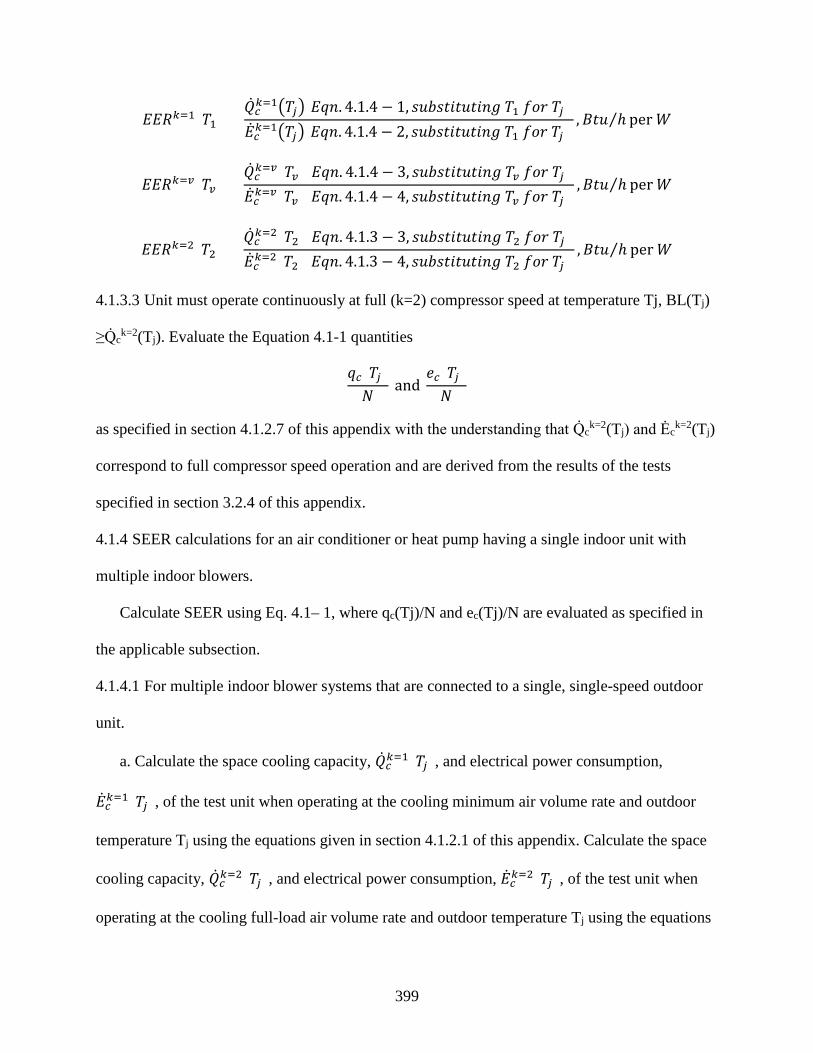
399
𝐸𝐸𝐸𝐸𝐸𝐸𝑘𝑘=1(𝑇𝑇1) =�̇�𝑄𝑐𝑐𝑘𝑘=1�𝑇𝑇𝑗𝑗�[𝐸𝐸𝑞𝑞𝑛𝑛. 4.1.4 − 1, 𝑠𝑠𝐵𝐵𝑠𝑠𝑠𝑠𝑡𝑡𝑠𝑠𝑡𝑡𝐵𝐵𝑡𝑡𝑠𝑠𝑛𝑛𝑠𝑠 𝑇𝑇1 𝑓𝑓𝑜𝑜𝑟𝑟 𝑇𝑇𝑗𝑗] �̇�𝐸𝑐𝑐𝑘𝑘=1�𝑇𝑇𝑗𝑗�[𝐸𝐸𝑞𝑞𝑛𝑛. 4.1.4 − 2, 𝑠𝑠𝐵𝐵𝑠𝑠𝑠𝑠𝑡𝑡𝑠𝑠𝑡𝑡𝐵𝐵𝑡𝑡𝑠𝑠𝑛𝑛𝑠𝑠 𝑇𝑇1 𝑓𝑓𝑜𝑜𝑟𝑟 𝑇𝑇𝑗𝑗]
,𝐵𝐵𝑡𝑡𝐵𝐵 ℎ⁄ per 𝑊𝑊
𝐸𝐸𝐸𝐸𝐸𝐸𝑘𝑘=𝑣𝑣(𝑇𝑇𝑣𝑣) =�̇�𝑄𝑐𝑐𝑘𝑘=𝑣𝑣(𝑇𝑇𝑣𝑣)[𝐸𝐸𝑞𝑞𝑛𝑛. 4.1.4 − 3, 𝑠𝑠𝐵𝐵𝑠𝑠𝑠𝑠𝑡𝑡𝑠𝑠𝑡𝑡𝐵𝐵𝑡𝑡𝑠𝑠𝑛𝑛𝑠𝑠 𝑇𝑇𝑣𝑣 𝑓𝑓𝑜𝑜𝑟𝑟 𝑇𝑇𝑗𝑗] �̇�𝐸𝑐𝑐𝑘𝑘=𝑣𝑣(𝑇𝑇𝑣𝑣)[𝐸𝐸𝑞𝑞𝑛𝑛. 4.1.4 − 4, 𝑠𝑠𝐵𝐵𝑠𝑠𝑠𝑠𝑡𝑡𝑠𝑠𝑡𝑡𝐵𝐵𝑡𝑡𝑠𝑠𝑛𝑛𝑠𝑠 𝑇𝑇𝑣𝑣 𝑓𝑓𝑜𝑜𝑟𝑟 𝑇𝑇𝑗𝑗]
,𝐵𝐵𝑡𝑡𝐵𝐵 ℎ⁄ per 𝑊𝑊
𝐸𝐸𝐸𝐸𝐸𝐸𝑘𝑘=2(𝑇𝑇2) =�̇�𝑄𝑐𝑐𝑘𝑘=2(𝑇𝑇2)[𝐸𝐸𝑞𝑞𝑛𝑛. 4.1.3 − 3, 𝑠𝑠𝐵𝐵𝑠𝑠𝑠𝑠𝑡𝑡𝑠𝑠𝑡𝑡𝐵𝐵𝑡𝑡𝑠𝑠𝑛𝑛𝑠𝑠 𝑇𝑇2 𝑓𝑓𝑜𝑜𝑟𝑟 𝑇𝑇𝑗𝑗] �̇�𝐸𝑐𝑐𝑘𝑘=2(𝑇𝑇2)[𝐸𝐸𝑞𝑞𝑛𝑛. 4.1.3 − 4, 𝑠𝑠𝐵𝐵𝑠𝑠𝑠𝑠𝑡𝑡𝑠𝑠𝑡𝑡𝐵𝐵𝑡𝑡𝑠𝑠𝑛𝑛𝑠𝑠 𝑇𝑇2 𝑓𝑓𝑜𝑜𝑟𝑟 𝑇𝑇𝑗𝑗]
,𝐵𝐵𝑡𝑡𝐵𝐵 ℎ⁄ per 𝑊𝑊
4.1.3.3 Unit must operate continuously at full (k=2) compressor speed at temperature Tj, BL(Tj)
≥Q̇ck=2(Tj). Evaluate the Equation 4.1-1 quantities
𝑞𝑞𝑐𝑐(𝑇𝑇𝑗𝑗)𝑁𝑁
and 𝑆𝑆𝑐𝑐(𝑇𝑇𝑗𝑗)𝑁𝑁
as specified in section 4.1.2.7 of this appendix with the understanding that Q̇ck=2(Tj) and Ėc
k=2(Tj)
correspond to full compressor speed operation and are derived from the results of the tests
specified in section 3.2.4 of this appendix.
4.1.4 SEER calculations for an air conditioner or heat pump having a single indoor unit with
multiple indoor blowers.
Calculate SEER using Eq. 4.1– 1, where qc(Tj)/N and ec(Tj)/N are evaluated as specified in
the applicable subsection.
4.1.4.1 For multiple indoor blower systems that are connected to a single, single-speed outdoor
unit.
a. Calculate the space cooling capacity, �̇�𝑄𝑐𝑐𝑘𝑘=1(𝑇𝑇𝑗𝑗), and electrical power consumption,
�̇�𝐸𝑐𝑐𝑘𝑘=1(𝑇𝑇𝑗𝑗), of the test unit when operating at the cooling minimum air volume rate and outdoor
temperature Tj using the equations given in section 4.1.2.1 of this appendix. Calculate the space
cooling capacity, �̇�𝑄𝑐𝑐𝑘𝑘=2(𝑇𝑇𝑗𝑗), and electrical power consumption, �̇�𝐸𝑐𝑐𝑘𝑘=2(𝑇𝑇𝑗𝑗), of the test unit when
operating at the cooling full-load air volume rate and outdoor temperature Tj using the equations

400
given in section 4.1.2.1 of this appendix. In evaluating the section 4.1.2.1 equations, determine
the quantities �̇�𝑄𝑐𝑐𝑘𝑘=1(82) and �̇�𝐸𝑐𝑐𝑘𝑘=1(82) from the B1 test, �̇�𝑄𝑐𝑐𝑘𝑘=1(95) and �̇�𝐸𝑐𝑐𝑘𝑘=1(95) from the Al
test, �̇�𝑄𝑐𝑐𝑘𝑘=2(82) and �̇�𝐸𝑐𝑐𝑘𝑘=2(82) from the B2 test, and �̇�𝑄𝑐𝑐𝑘𝑘=2(95) and �̇�𝐸𝑐𝑐𝑘𝑘=2(95) from the A2 test.
Evaluate all eight quantities as specified in section 3.3 of this appendix. Refer to section 3.2.2.1
and Table 5 of this appendix for additional information on the four referenced laboratory tests.
b. Determine the cooling mode cyclic degradation coefficient, CDc, as per sections 3.2.2.1
and 3.5 to 3.5.3 of this appendix. Assign this same value to CDc(K=2).
c. Except for using the above values of �̇�𝑄𝑐𝑐𝑘𝑘=1(𝑇𝑇𝑗𝑗), �̇�𝐸𝑐𝑐𝑘𝑘=1(𝑇𝑇𝑗𝑗), �̇�𝐸𝑐𝑐𝑘𝑘=2(𝑇𝑇𝑗𝑗), �̇�𝑄𝑐𝑐𝑘𝑘=2(𝑇𝑇𝑗𝑗), CDc, and
CDc (K=2), calculate the quantities qc(Tj)/N and ec(Tj)/N as specified in section 4.1.3.1 of this
appendix for cases where �̇�𝑄𝑐𝑐𝑘𝑘=1(𝑇𝑇𝑗𝑗) ≥ BL(Tj). For all other outdoor bin temperatures, Tj,
calculate qc(Tj)/N and ec(Tj)/N as specified in section 4.1.3.3 of this appendix if �̇�𝑄𝑐𝑐𝑘𝑘=2(𝑇𝑇𝑗𝑗) > BL
(Tj) or as specified in section 4.1.3.4 of this appendix if �̇�𝑄𝑐𝑐𝑘𝑘=2(𝑇𝑇𝑗𝑗) ≤ BL(Tj).
4.1.4.2 For multiple indoor blower systems that are connected to either a lone outdoor unit
having a two-capacity compressor or to two separate single-speed outdoor units of identical
model, calculate the quantities qc(Tj)/N and ec(Tj)/N as specified in section 4.1.3 of this
appendix.
4.2 Heating Seasonal Performance Factor (HSPF) Calculations.
Unless an approved alternative efficiency determination method is used, as set forth in 10
CFR 429.70(e), HSPF must be calculated as follows: Six generalized climatic regions are
depicted in Figure 1 and otherwise defined in Table 19. For each of these regions and for each
applicable standardized design heating requirement, evaluate the heating seasonal performance
factor using,

401
Equation 4.2-1 𝐻𝐻𝑁𝑁𝑃𝑃𝑁𝑁 =∑ 𝑛𝑛𝑗𝑗∗𝐵𝐵𝑃𝑃(𝑇𝑇𝑗𝑗)𝐽𝐽𝑗𝑗
∑ 𝑑𝑑ℎ(𝑇𝑇𝑗𝑗)𝐽𝐽𝑗𝑗 +∑ 𝐸𝐸𝑅𝑅(𝑇𝑇𝑗𝑗)𝐽𝐽
𝑗𝑗∗ 𝑁𝑁𝑑𝑑𝑑𝑑𝑓𝑓 =
∑ �𝑚𝑚𝑗𝑗𝑁𝑁 ∗𝐵𝐵𝑃𝑃(𝑇𝑇𝑗𝑗)�𝐽𝐽
𝑗𝑗
∑𝑒𝑒ℎ(𝑇𝑇𝑗𝑗)𝑁𝑁
𝐽𝐽𝑗𝑗 +∑
𝑅𝑅𝑅𝑅(𝑇𝑇𝑗𝑗)𝑁𝑁
𝐽𝐽𝑗𝑗
∗ 𝑁𝑁𝑑𝑑𝑑𝑑𝑓𝑓
where:
eh(Tj) / N = The ratio of the electrical energy consumed by the heat pump during periods
of the space heating season when the outdoor temperature fell within the range
represented by bin temperature Tj to the total number of hours in the heating season (N),
W. For heat pumps having a heat comfort controller, this ratio may also include electrical
energy used by resistive elements to maintain a minimum air delivery temperature (see
4.2.5).
RH(Tj) / N= The ratio of the electrical energy used for resistive space heating during
periods when the outdoor temperature fell within the range represented by bin
temperature Tj to the total number of hours in the heating season (N), W. Except as noted
in section 4.2.5 of this appendix, resistive space heating is modeled as being used to meet
that portion of the building load that the heat pump does not meet because of insufficient
capacity or because the heat pump automatically turns off at the lowest outdoor
temperatures. For heat pumps having a heat comfort controller, all or part of the electrical
energy used by resistive heaters at a particular bin temperature may be reflected in eh(Tj) /
N (see section 4.2.5 of this appendix).
Tj = the outdoor bin temperature, °F. Outdoor temperatures are “binned” such that
calculations are only performed based one temperature within the bin. Bins of 5 °F are
used.
nj / N= Fractional bin hours for the heating season; the ratio of the number of hours
during the heating season when the outdoor temperature fell within the range represented

402
by bin temperature Tj to the total number of hours in the heating season, dimensionless.
Obtain nj/N values from Table 19.
j = the bin number, dimensionless.
J = for each generalized climatic region, the total number of temperature bins,
dimensionless. Referring to Table 19, J is the highest bin number (j) having a nonzero
entry for the fractional bin hours for the generalized climatic region of interest.
Fdef = the demand defrost credit described in section 3.9.2 of this appendix,
dimensionless.
BL(Tj) = the building space conditioning load corresponding to an outdoor temperature
of Tj; the heating season building load also depends on the generalized climatic region's
outdoor design temperature and the design heating requirement, Btu/h.

403
Table 19 Generalized Climatic Region Information
Region Number I II III IV V VI
Heating Load Hours, HLH 750 1250 1750 2250 2750 *2750
Outdoor Design Temperature, TOD 37 27 17 5 −10 30
j Tj (°F) Fractional Bin Hours, nj/N
1 62 .291 .215 .153 .132 .106 .113
2 57 .239 .189 .142 .111 .092 .206
3 52 .194 .163 .138 .103 .086 .215
4 47 .129 .143 .137 .093 .076 .204
5 42 .081 .112 .135 .100 .078 .141
6 37 .041 .088 .118 .109 .087 .076
7 32 .019 .056 .092 .126 .102 .034
8 27 .005 .024 .047 .087 .094 .008
9 22 .001 .008 .021 .055 .074 .003
10 17 0 .002 .009 .036 .055 0
11 12 0 0 .005 .026 .047 0
12 7 0 0 .002 .013 .038 0
13 2 0 0 .001 .006 .029 0
14 −3 0 0 0 .002 .018 0
15 −8 0 0 0 .001 .010 0
16 −13 0 0 0 0 .005 0
17 −18 0 0 0 0 .002 0
18 −23 0 0 0 0 .001 0 *Pacific Coast Region.
Evaluate the building heating load using
Equation 4.2-2 𝐵𝐵𝑈𝑈�𝑇𝑇𝑗𝑗� = (65−𝑇𝑇𝑗𝑗)65−𝑇𝑇𝑂𝑂𝑂𝑂
∗ 𝑈𝑈 ∗ 𝐷𝐷𝐻𝐻𝐸𝐸
where:

404
TOD = the outdoor design temperature, °F. An outdoor design temperature is specified for
each generalized climatic region in Table 19.
C = 0.77, a correction factor which tends to improve the agreement between calculated
and measured building loads, dimensionless.
DHR = the design heating requirement (see section 1.2 of this appendix, Definitions),
Btu/h.
Calculate the minimum and maximum design heating requirements for each generalized
climatic region as follows:
𝐷𝐷𝐻𝐻𝐸𝐸𝑚𝑚𝑖𝑖𝑛𝑛 = ��̇�𝑄ℎ𝑘𝑘(47) ∗ �
65 − 𝑇𝑇𝐶𝐶𝐷𝐷60
� ,𝑓𝑓𝑜𝑜𝑟𝑟 𝐸𝐸𝑆𝑆𝑠𝑠𝑠𝑠𝑜𝑜𝑛𝑛𝑠𝑠 𝑁𝑁, 𝑁𝑁𝑁𝑁, 𝑁𝑁𝑁𝑁𝑁𝑁, 𝑁𝑁𝑉𝑉, & 𝑉𝑉𝑁𝑁
�̇�𝑄ℎ𝑘𝑘(47), 𝑓𝑓𝑜𝑜𝑟𝑟 𝐸𝐸𝑆𝑆𝑠𝑠𝑠𝑠𝑜𝑜𝑛𝑛 𝑉𝑉�
and
𝐷𝐷𝐻𝐻𝐸𝐸𝑚𝑚𝑉𝑉𝑚𝑚 = �2 ∗ �̇�𝑄ℎ𝑘𝑘(47) ∗ �65 − 𝑇𝑇𝐶𝐶𝐷𝐷
60� ,𝑓𝑓𝑜𝑜𝑟𝑟 𝐸𝐸𝑆𝑆𝑠𝑠𝑠𝑠𝑜𝑜𝑛𝑛𝑠𝑠 𝑁𝑁, 𝑁𝑁𝑁𝑁, 𝑁𝑁𝑁𝑁𝑁𝑁, 𝑁𝑁𝑉𝑉, & 𝑉𝑉𝑁𝑁
2.2 ∗ �̇�𝑄ℎ𝑘𝑘(47), 𝑓𝑓𝑜𝑜𝑟𝑟 𝐸𝐸𝑆𝑆𝑠𝑠𝑠𝑠𝑜𝑜𝑛𝑛 𝑉𝑉�
Rounded to the nearest standardized DHR given in Table 19
where Q̇hk(47) is expressed in units of Btu/h and otherwise defined as follows:
a. For a single-speed heat pump tested as per section 3.6.1 of this appendix, Q̇hk(47) =
Q̇h(47), the space heating capacity determined from the H1 test.
b. For a variable-speed heat pump, a section 3.6.2 single-speed heat pump, or a two-
capacity heat pump not covered by item 3, Q̇nk(47) = Q̇n
k=2(47), the space heating capacity
determined from the H12 test.
c. For two-capacity, northern heat pumps (see section 1.2 of this appendix, Definitions),
Q̇kh(47) = Q̇k=1
h(47), the space heating capacity determined from the H11 test.

405
If the optional H1N test is conducted on a variable-speed heat pump, the manufacturer has the
option of defining Q̇kh(47) as specified above in item 2 or as Q̇k
h(47)=Q̇k=Nh(47), the space
heating capacity determined from the H1N test.
For all heat pumps, HSPF accounts for the heating delivered and the energy consumed by
auxiliary resistive elements when operating below the balance point. This condition occurs when
the building load exceeds the space heating capacity of the heat pump condenser. For HSPF
calculations for all heat pumps, see either section 4.2.1, 4.2.2, 4.2.3, or 4.2.4 of this appendix,
whichever applies.
For heat pumps with heat comfort controllers (see section 1.2 of this appendix, Definitions),
HSPF also accounts for resistive heating contributed when operating above the heat-pump-plus-
comfort-controller balance point as a result of maintaining a minimum supply temperature. For
heat pumps having a heat comfort controller, see section 4.2.5 of this appendix for the additional
steps required for calculating the HSPF.
Table 20 Standardized Design Heating Requirements (Btu/h)
5,000 25,000 50,000 90,000
10,000 30,000 60,000 100,000
15,000 35,000 70,000 110,000
20,000 40,000 80,000 130,000
4.2.1 Additional steps for calculating the HSPF of a blower coil system heat pump having a
single-speed compressor and either a fixed-speed indoor blower or a constant-air-volume-rate
indoor blower installed, or a coil-only system heat pump.
Equation 4.2.1-1 𝑑𝑑ℎ(𝑇𝑇𝑗𝑗)𝑁𝑁
= 𝑋𝑋�𝑇𝑇𝑗𝑗�∗�̇�𝐸ℎ�𝑇𝑇𝑗𝑗�∗𝛿𝛿�𝑇𝑇𝑗𝑗�𝑃𝑃𝑃𝑃𝐹𝐹𝑗𝑗
∗ 𝑛𝑛𝑗𝑗𝑁𝑁

406
Equation 4.2.1-2 𝐸𝐸𝑅𝑅(𝑇𝑇𝑗𝑗)
𝑁𝑁= 𝐵𝐵𝑃𝑃�𝑇𝑇𝑗𝑗�−[𝑋𝑋�𝑇𝑇𝑗𝑗�∗�̇�𝑄ℎ�𝑇𝑇𝑗𝑗�∗𝛿𝛿�𝑇𝑇𝑗𝑗�]
3.413𝐵𝐵𝑓𝑓𝐵𝐵 ℎ⁄𝑊𝑊
∗ 𝑛𝑛𝑗𝑗𝑁𝑁
where:
𝑋𝑋�𝑇𝑇𝑗𝑗� = �𝐵𝐵𝑈𝑈�𝑇𝑇𝐽𝐽� �̇�𝑄ℎ�𝑇𝑇𝑗𝑗��
𝑜𝑜𝑟𝑟1
�
whichever is less; the heating mode load factor for temperature bin j, dimensionless.
Q̇h(Tj) = the space heating capacity of the heat pump when operating at outdoor
temperature Tj, Btu/h.
Ėh(Tj) = the electrical power consumption of the heat pump when operating at outdoor
temperature Tj, W.
δ(Tj) = the heat pump low temperature cut-out factor, dimensionless.
PLFj = 1 − ĊDh · [1 −X(Tj)] the part load factor, dimensionless.
Use Equation 4.2-2 to determine BL(Tj). Obtain fractional bin hours for the heating season,
nj/N, from Table 19.
Determine the low temperature cut-out factor using
Equation 4.2.1-3 𝛿𝛿�𝑇𝑇𝑗𝑗� =
⎩⎪⎨
⎪⎧ 0, 𝑠𝑠𝑓𝑓 𝑇𝑇𝑗𝑗 ≤ 𝑇𝑇𝑜𝑜𝑓𝑓𝑓𝑓 𝑎𝑎𝑛𝑛𝑑𝑑 �̇�𝑄ℎ�𝑇𝑇𝑗𝑗�
3.413∗�̇�𝐸ℎ�𝑇𝑇𝑗𝑗�< 1
1 2⁄ , 𝑠𝑠𝑓𝑓 𝑇𝑇𝑜𝑜𝑓𝑓𝑓𝑓 < 𝑇𝑇𝑗𝑗 ≤ 𝑇𝑇𝑜𝑜𝑛𝑛 𝑎𝑎𝑛𝑛𝑑𝑑 �̇�𝑄ℎ�𝑇𝑇𝑗𝑗�3.413∗�̇�𝐸ℎ�𝑇𝑇𝑗𝑗�
≥ 1
1, 𝑠𝑠𝑓𝑓 𝑇𝑇𝑗𝑗 > 𝑇𝑇𝑜𝑜𝑛𝑛 𝑎𝑎𝑛𝑛𝑑𝑑 �̇�𝑄ℎ�𝑇𝑇𝑗𝑗�3.413∗�̇�𝐸ℎ�𝑇𝑇𝑗𝑗�
≥ 1 ⎭⎪⎬
⎪⎫
where:
Toff = the outdoor temperature when the compressor is automatically shut off, °F. (If no
such temperature exists, Tj is always greater than Toff and Ton).
Ton = the outdoor temperature when the compressor is automatically turned back on, if
applicable, following an automatic shut-off, °F.

407
Calculate Q̇h(Tj) and Ėh(Tj) using,
Equation 4.2.1-4 �̇�𝑄ℎ�𝑇𝑇𝑗𝑗� = ��̇�𝑄ℎ(17) +
[�̇�𝑄ℎ(47)−�̇�𝑄ℎ(17)]∗(𝑇𝑇𝑗𝑗−17)47−17
, 𝑠𝑠𝑓𝑓 𝑇𝑇𝑗𝑗 ≥ 45 ℉ 𝑜𝑜𝑟𝑟 𝑇𝑇𝑗𝑗 ≤ 17 ℉
�̇�𝑄ℎ(17) +[�̇�𝑄ℎ(35)−�̇�𝑄ℎ(17)]∗(𝑇𝑇𝑗𝑗−17)
35−17, 𝑠𝑠𝑓𝑓 17 ℉ < 𝑇𝑇𝑗𝑗 < 45 ℉
Equation 4.2.1-5
�̇�𝐸ℎ�𝑇𝑇𝑗𝑗�
=
⎩⎪⎨
⎪⎧�̇�𝐸ℎ(17) +
��̇�𝐸ℎ(47) − �̇�𝐸ℎ(17)� ∗ (𝑇𝑇𝑗𝑗 − 17)47 − 17
, 𝑠𝑠𝑓𝑓 𝑇𝑇𝑗𝑗 ≥ 45 ℉ 𝑜𝑜𝑟𝑟 𝑇𝑇𝑗𝑗 ≤ 17 ℉
�̇�𝐸ℎ(17) +��̇�𝐸ℎ(35) − �̇�𝐸ℎ(17)� ∗ (𝑇𝑇𝑗𝑗 − 17)
35 − 17, 𝑠𝑠𝑓𝑓 17 ℉ < 𝑇𝑇𝑗𝑗 < 45 ℉
where Q̇h(47) and Ėh(47) are determined from the H1 test and calculated as specified in
section 3.7 of this appendix; Q̇h(35) and Ėh(35) are determined from the H2 test and calculated as
specified in section 3.9.1 of this appendix; and Q̇h(17) and Ėh(17) are determined from the H3
test and calculated as specified in section 3.10 of this appendix.
4.2.2 Additional steps for calculating the HSPF of a heat pump having a single-speed compressor
and a variable-speed, variable-air-volume-rate indoor blower.
The manufacturer must provide information about how the indoor air volume rate or the
indoor blower speed varies over the outdoor temperature range of 65 °F to −23 °F. Calculate the
quantities
𝑆𝑆ℎ(𝑇𝑇𝑗𝑗)𝑁𝑁
and 𝐸𝐸𝐻𝐻(𝑇𝑇𝑗𝑗)𝑁𝑁
in Equation 4.2-1 as specified in section 4.2.1 of this appendix with the exception of replacing
references to the H1C test and section 3.6.1 of this appendix with the H1C1 test and section 3.6.2
of this appendix. In addition, evaluate the space heating capacity and electrical power
consumption of the heat pump Q̇h(Tj) and Ėh(Tj) using

408
Equation 4.2.2-1 �̇�𝑄ℎ�𝑇𝑇𝑗𝑗� = �̇�𝑄ℎ𝑘𝑘=1�𝑇𝑇𝑗𝑗� + �̇�𝑄ℎ𝑘𝑘=2�𝑇𝑇𝑗𝑗�−�̇�𝑄ℎ
𝑘𝑘=1�𝑇𝑇𝑗𝑗�FPℎ
𝑘𝑘=2−FPℎ𝑘𝑘=1 ∗ �FPℎ�𝑇𝑇𝑗𝑗� − FPℎ𝑘𝑘=1�
Equation 4.2.2-2 �̇�𝐸ℎ�𝑇𝑇𝑗𝑗� = �̇�𝐸ℎ𝑘𝑘=1�𝑇𝑇𝑗𝑗� + �̇�𝐸ℎ𝑘𝑘=2�𝑇𝑇𝑗𝑗�−�̇�𝐸ℎ
𝑘𝑘=1�𝑇𝑇𝑗𝑗�FPℎ
𝑘𝑘=2−FPℎ𝑘𝑘=1 ∗ �FPℎ�𝑇𝑇𝑗𝑗� − FPℎ𝑘𝑘=1�
where the space heating capacity and electrical power consumption at both low capacity
(k=1) and high capacity (k=2) at outdoor temperature Tj are determined using
Equation 4.2.2-3 𝑄𝑄ℎ�̇�𝑘�𝑇𝑇𝑗𝑗� = ��̇�𝑄ℎ𝑘𝑘(17) +
��̇�𝑄ℎ𝑘𝑘(47)−�̇�𝑄ℎ
𝑘𝑘(17)�∗(𝑇𝑇𝑗𝑗−17)
47−17, 𝑠𝑠𝑓𝑓 𝑇𝑇𝑗𝑗 ≥ 45 ℉ 𝑜𝑜𝑟𝑟 𝑇𝑇𝑗𝑗 ≤ 17 ℉
�̇�𝑄ℎ𝑘𝑘(17) +��̇�𝑄ℎ
𝑘𝑘(35)−�̇�𝑄ℎ𝑘𝑘(17)�∗(𝑇𝑇𝑗𝑗−17)
35−17, 𝑠𝑠𝑓𝑓 17 ℉ < 𝑇𝑇𝑗𝑗 < 45 ℉
Equation 4.2.2-4
�̇�𝐸ℎ𝑘𝑘�𝑇𝑇𝑗𝑗� =
⎩⎪⎨
⎪⎧�̇�𝐸ℎ𝑘𝑘(17) +
��̇�𝐸ℎ𝑘𝑘(47) − �̇�𝐸ℎ𝑘𝑘(17)� ∗ (𝑇𝑇𝑗𝑗 − 17)47 − 17
, 𝑠𝑠𝑓𝑓 𝑇𝑇𝑗𝑗 ≥ 45 ℉ 𝑜𝑜𝑟𝑟 𝑇𝑇𝑗𝑗 ≤ 17 ℉
�̇�𝐸ℎ𝑘𝑘(17) +�𝐸𝐸ℎ�̇�𝑘(35) − �̇�𝐸ℎ𝑘𝑘(17)� ∗ (𝑇𝑇𝑗𝑗 − 17)
35 − 17, 𝑠𝑠𝑓𝑓 17 ℉ < 𝑇𝑇𝑗𝑗 < 45 ℉
For units where indoor blower speed is the primary control variable, FPhk=1 denotes the fan
speed used during the required H11 and H31 tests (see Table 11), FPhk=2 denotes the fan speed
used during the required H12, H22, and H32 tests, and FPh(Tj) denotes the fan speed used by the
unit when the outdoor temperature equals Tj. For units where indoor air volume rate is the
primary control variable, the three FPh's are similarly defined only now being expressed in terms
of air volume rates rather than fan speeds. Determine Q̇hk=1(47) and Ėh
k=1(47) from the H11 test,
and Q̇hk=2(47) and Ėh
k=2(47) from the H12 test. Calculate all four quantities as specified in section
3.7 of this appendix. Determine Q̇hk=1(35) and Ėh
k=1(35) as specified in section 3.6.2 of this
appendix; determine Q̇hk=2(35) and Ėh
k=2(35) and from the H22 test and the calculation specified
in section 3.9 of this appendix. Determine Q̇hk=1(17) and Ėh
k=1(17 from the H31 test, and
Q̇hk=2(17) and Ėh
k=2(17) from the H32 test. Calculate all four quantities as specified in section
3.10 of this appendix.

409
4.2.3 Additional steps for calculating the HSPF of a heat pump having a two-capacity
compressor.
The calculation of the Equation 4.2-1 quantities differ depending upon whether the heat
pump would operate at low capacity (section 4.2.3.1 of this appendix), cycle between low and
high capacity (section 4.2.3.2 of this appendix), or operate at high capacity (sections 4.2.3.3 and
4.2.3.4 of this appendix) in responding to the building load. For heat pumps that lock out low
capacity operation at low outdoor temperatures, the manufacturer must supply information
regarding the cutoff temperature(s) so that the appropriate equations can be selected.
𝑆𝑆ℎ(𝑇𝑇𝑗𝑗)𝑁𝑁
and 𝐸𝐸𝐻𝐻(𝑇𝑇𝑗𝑗)𝑁𝑁
a. Evaluate the space heating capacity and electrical power consumption of the heat pump
when operating at low compressor capacity and outdoor temperature Tj using
�̇�𝑄ℎ𝑘𝑘=1�𝑇𝑇𝑗𝑗� =
⎩⎪⎪⎨
⎪⎪⎧ �̇�𝑄ℎ𝑘𝑘=1(47) +
��̇�𝑄ℎ𝑘𝑘=1(62) − �̇�𝑄ℎ𝑘𝑘=1(47)� ∗ (𝑇𝑇𝑗𝑗 − 47)62 − 47
, 𝑠𝑠𝑓𝑓 𝑇𝑇𝑗𝑗 ≥ 40 ℉
�̇�𝑄ℎ𝑘𝑘=1(17) +��̇�𝑄ℎ𝑘𝑘=1(35) − �̇�𝑄ℎ𝑘𝑘=1(17)� ∗ (𝑇𝑇𝑗𝑗 − 17)
35 − 17, 𝑠𝑠𝑓𝑓 17 ℉ ≤ 𝑇𝑇𝑗𝑗 < 40 ℉
�̇�𝑄ℎ𝑘𝑘=1(17) +��̇�𝑄ℎ𝑘𝑘=1(47) − �̇�𝑄ℎ𝑘𝑘=1(17)� ∗ (𝑇𝑇𝑗𝑗 − 17)
47 − 17, 𝑠𝑠𝑓𝑓 𝑇𝑇𝑗𝑗 < 17 ℉
�̇�𝐸ℎ𝑘𝑘=1�𝑇𝑇𝑗𝑗� =
⎩⎪⎨
⎪⎧ �̇�𝐸ℎ𝑘𝑘=1(47) +
��̇�𝐸ℎ𝑘𝑘=1(62)−�̇�𝐸ℎ
𝑘𝑘=1(47)�∗(𝑇𝑇𝑗𝑗−47)
62−47, 𝑠𝑠𝑓𝑓 𝑇𝑇𝑗𝑗 ≥ 40 ℉
�̇�𝐸ℎ𝑘𝑘=1(17) +��̇�𝐸ℎ
𝑘𝑘=1(35)−�̇�𝐸ℎ𝑘𝑘=1(17)�∗(𝑇𝑇𝑗𝑗−17)
35−17, 𝑠𝑠𝑓𝑓 17 ℉ ≤ 𝑇𝑇𝑗𝑗 < 40 ℉
�̇�𝐸ℎ𝑘𝑘=1(17) +��̇�𝐸ℎ
𝑘𝑘=1(47)−�̇�𝐸ℎ𝑘𝑘=1(17)�∗(𝑇𝑇𝑗𝑗−17)
47−17, 𝑠𝑠𝑓𝑓 𝑇𝑇𝑗𝑗 < 17 ℉
b. Evaluate the space heating capacity and electrical power consumption (Q̇hk=2(Tj) and
Ėhk=2 (Tj)) of the heat pump when operating at high compressor capacity and outdoor temperature
Tj by solving Equations 4.2.2-3 and 4.2.2-4, respectively, for k=2. Determine Q̇hk=1(62) and
Ėhk=1(62) from the H01 test, Q̇h
k=1(47) and Ėhk=1(47) from the H11 test, and Q̇h
k=2(47) and
Ėhk=2(47) from the H12 test. Calculate all six quantities as specified in section 3.7 of this

410
appendix. Determine Q̇hk=2(35) and Ėh
k=2(35) from the H22 test and, if required as described in
section 3.6.3 of this appendix, determine Q̇hk=1(35) and Ėh
k=1(35) from the H21 test. Calculate the
required 35 °F quantities as specified in section 3.9 of this appendix. Determine Q̇hk=2(17) and
Ėhk=2(17) from the H32 test and, if required as described in section 3.6.3 of this appendix,
determine Q̇hk=1(17) and Ėh
k=1(17) from the H31 test. Calculate the required 17 °F quantities as
specified in section 3.10 of this appendix.
4.2.3.1 Steady-state space heating capacity when operating at low compressor capacity is greater
than or equal to the building heating load at temperature Tj, Q̇hk=1(Tj) ≥BL(Tj).
Equation 4.2.3-1 𝑑𝑑ℎ(𝑇𝑇𝑗𝑗)𝑁𝑁
= 𝑋𝑋𝑘𝑘=1�𝑇𝑇𝑗𝑗�∗�̇�𝐸ℎ𝑘𝑘=1�𝑇𝑇𝑗𝑗�∗𝛿𝛿�𝑇𝑇𝑗𝑗�𝑃𝑃𝑃𝑃𝐹𝐹𝑗𝑗
∗ 𝑛𝑛𝑗𝑗𝑁𝑁
Equation 4.2.3-2 𝐸𝐸𝑅𝑅(𝑇𝑇𝑗𝑗)
𝑁𝑁= 𝐵𝐵𝑃𝑃�𝑇𝑇𝑗𝑗�∗[1−𝛿𝛿�𝑇𝑇𝑗𝑗�]
3.413𝐵𝐵𝑓𝑓𝐵𝐵 ℎ⁄𝑊𝑊
∗ 𝑛𝑛𝑗𝑗𝑁𝑁
where:
Xk=1(Tj) = BL(Tj) / Q̇hk=1(Tj), the heating mode low capacity load factor for temperature
bin j, dimensionless.
PLFj = 1 − CDh · [ 1 − Xk=1(Tj) ], the part load factor, dimensionless.
δ′(Tj) = the low temperature cutoff factor, dimensionless.
Determine the low temperature cut-out factor using
Equation 4.2.3-3 𝛿𝛿�𝑇𝑇𝑗𝑗� = �0, 𝑠𝑠𝑓𝑓 𝑇𝑇𝑗𝑗 ≤ 𝑇𝑇𝑜𝑜𝑓𝑓𝑓𝑓
1 2⁄ , 𝑠𝑠𝑓𝑓 𝑇𝑇𝑜𝑜𝑓𝑓𝑓𝑓 < 𝑇𝑇𝑗𝑗 ≤ 𝑇𝑇𝑜𝑜𝑛𝑛1, 𝑠𝑠𝑓𝑓 𝑇𝑇𝑗𝑗 > 𝑇𝑇𝑜𝑜𝑛𝑛
where Toff and Ton are defined in section 4.2.1 of this appendix. Use the calculations given in
section 4.2.3.3 of this appendix, and not the above, if:
a. The heat pump locks out low capacity operation at low outdoor temperatures and
b. Tj is below this lockout threshold temperature.

411
4.2.3.2 Heat pump alternates between high (k=2) and low (k=1) compressor capacity to satisfy
the building heating load at a temperature Tj, Q̇hk=1(Tj) <BL(Tj) <Q̇h
k=2(Tj).
Calculate 𝐸𝐸𝑅𝑅(𝑇𝑇𝑗𝑗)
𝑁𝑁 using Equation 4.2.3-2. Evaluate
𝑑𝑑ℎ(𝑇𝑇𝑗𝑗)𝑁𝑁
using
𝑑𝑑ℎ(𝑇𝑇𝑗𝑗)𝑁𝑁
=[𝑋𝑋𝑘𝑘=1�𝑇𝑇𝑗𝑗� ∗ �̇�𝐸ℎ𝑘𝑘=1�𝑇𝑇𝑗𝑗� + 𝑋𝑋𝑘𝑘=2�𝑇𝑇𝑗𝑗� ∗ �̇�𝐸ℎ𝑘𝑘=2�𝑇𝑇𝑗𝑗�] ∗ 𝛿𝛿�𝑇𝑇𝑗𝑗� ∗𝑛𝑛𝑗𝑗𝑁𝑁
where:
𝑋𝑋𝑘𝑘=1�𝑇𝑇𝑗𝑗� =�̇�𝑄ℎ𝑘𝑘=2�𝑇𝑇𝑗𝑗� − 𝐵𝐵𝑈𝑈(𝑇𝑇𝑗𝑗)�̇�𝑄ℎ𝑘𝑘=2�𝑇𝑇𝑗𝑗� − �̇�𝑄ℎ𝑘𝑘=1�𝑇𝑇𝑗𝑗�
Xk=2(Tj) = 1 − Xk=1(Tj) the heating mode, high capacity load factor for temperature bin j,
dimensionless.
Determine the low temperature cut-out factor, δ′(Tj), using Equation 4.2.3-3.
4.2.3.3 Heat pump only operates at high (k=2) compressor capacity at temperature Tj and its
capacity is greater than the building heating load, BL(Tj) <Q̇hk=2(Tj). This section applies to units
that lock out low compressor capacity operation at low outdoor temperatures.
Calculate 𝐸𝐸𝑅𝑅�𝑇𝑇𝑗𝑗�
𝑁𝑁 using Equation 4.2.3-2. Evaluate
𝑑𝑑ℎ�𝑇𝑇𝑗𝑗�𝑁𝑁
using
𝑆𝑆ℎ(𝑇𝑇𝑗𝑗)𝑁𝑁
=𝑋𝑋𝑘𝑘=2�𝑇𝑇𝑗𝑗� ∗ �̇�𝐸ℎ𝑘𝑘=2�𝑇𝑇𝑗𝑗� ∗ 𝛿𝛿�𝑇𝑇𝑗𝑗�
𝑃𝑃𝑈𝑈𝑁𝑁𝑗𝑗∗𝑛𝑛𝑗𝑗𝑁𝑁
where:
Xk=2(Tj)= BL(Tj)/Q̇hk=2(Tj). 𝑃𝑃𝑈𝑈𝑁𝑁𝑗𝑗 = 1 − 𝑈𝑈𝐷𝐷ℎ(𝑘𝑘 = 2) ∗ [1 − 𝑋𝑋𝑘𝑘=2(𝑇𝑇𝑗𝑗)
If the H1C2 test described in section 3.6.3 and Table 12 of this appendix is not conducted, set
CDh (k=2) equal to the default value specified in section 3.8.1 of this appendix.
Determine the low temperature cut-out factor, δ(Tj), using Equation 4.2.3-3.
4.2.3.4 Heat pump must operate continuously at high (k=2) compressor capacity at temperature
Tj, BL(Tj) ≥Q̇hk=2(Tj).
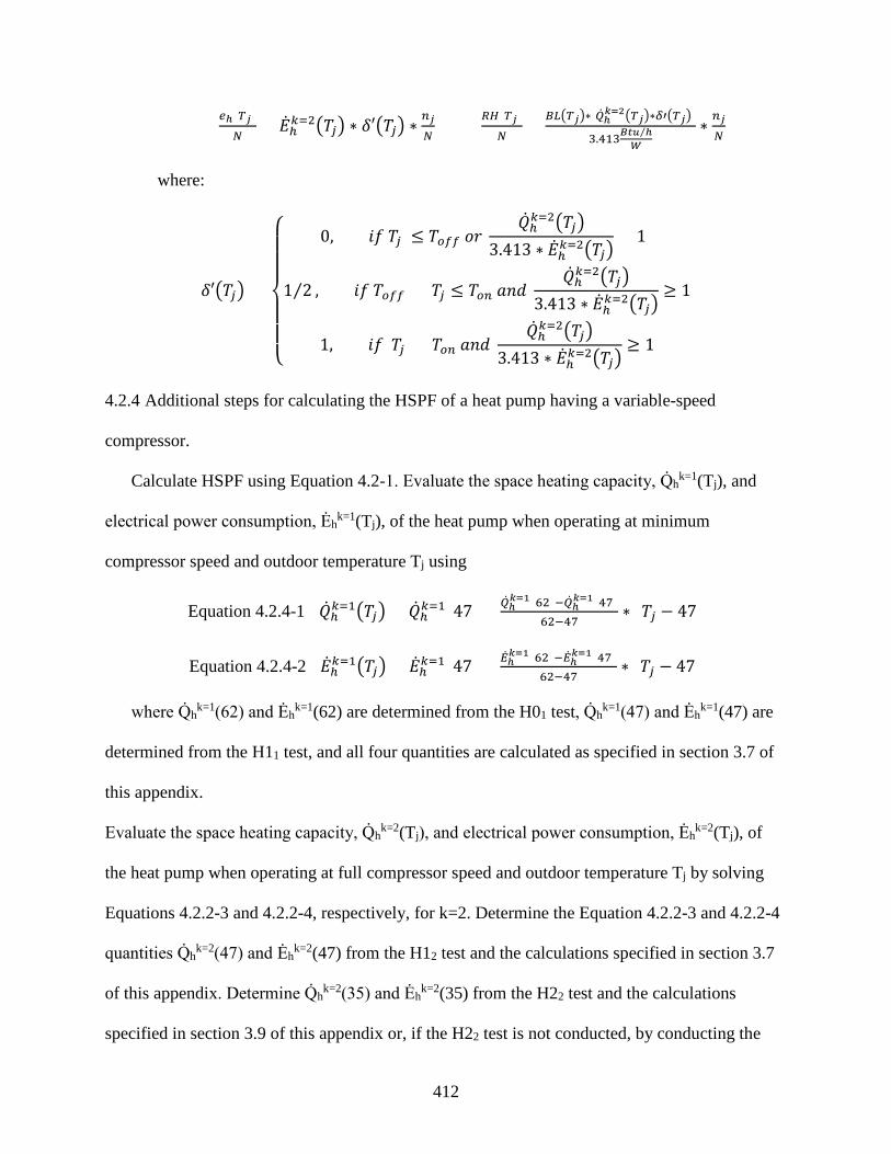
412
𝑑𝑑ℎ(𝑇𝑇𝑗𝑗)𝑁𝑁
= �̇�𝐸ℎ𝑘𝑘=2�𝑇𝑇𝑗𝑗� ∗ 𝛿𝛿′�𝑇𝑇𝑗𝑗� ∗𝑛𝑛𝑗𝑗𝑁𝑁
𝐸𝐸𝑅𝑅(𝑇𝑇𝑗𝑗)
𝑁𝑁= 𝐵𝐵𝑃𝑃�𝑇𝑇𝑗𝑗�∗[�̇�𝑄ℎ
𝑘𝑘=2�𝑇𝑇𝑗𝑗�∗𝛿𝛿′�𝑇𝑇𝑗𝑗�]
3.413𝐵𝐵𝑓𝑓𝐵𝐵 ℎ⁄𝑊𝑊
∗ 𝑛𝑛𝑗𝑗𝑁𝑁
where:
𝛿𝛿′�𝑇𝑇𝑗𝑗� =
⎩⎪⎪⎨
⎪⎪⎧ 0, 𝑠𝑠𝑓𝑓 𝑇𝑇𝑗𝑗 ≤ 𝑇𝑇𝑜𝑜𝑓𝑓𝑓𝑓 𝑜𝑜𝑟𝑟
�̇�𝑄ℎ𝑘𝑘=2�𝑇𝑇𝑗𝑗�3.413 ∗ �̇�𝐸ℎ𝑘𝑘=2�𝑇𝑇𝑗𝑗�
< 1
1 2⁄ , 𝑠𝑠𝑓𝑓 𝑇𝑇𝑜𝑜𝑓𝑓𝑓𝑓 < 𝑇𝑇𝑗𝑗 ≤ 𝑇𝑇𝑜𝑜𝑛𝑛 𝑎𝑎𝑛𝑛𝑑𝑑 �̇�𝑄ℎ𝑘𝑘=2�𝑇𝑇𝑗𝑗�
3.413 ∗ �̇�𝐸ℎ𝑘𝑘=2�𝑇𝑇𝑗𝑗�≥ 1
1, 𝑠𝑠𝑓𝑓 𝑇𝑇𝑗𝑗 > 𝑇𝑇𝑜𝑜𝑛𝑛 𝑎𝑎𝑛𝑛𝑑𝑑 �̇�𝑄ℎ𝑘𝑘=2�𝑇𝑇𝑗𝑗�
3.413 ∗ �̇�𝐸ℎ𝑘𝑘=2�𝑇𝑇𝑗𝑗�≥ 1
4.2.4 Additional steps for calculating the HSPF of a heat pump having a variable-speed
compressor.
Calculate HSPF using Equation 4.2-1. Evaluate the space heating capacity, Q̇hk=1(Tj), and
electrical power consumption, Ėhk=1(Tj), of the heat pump when operating at minimum
compressor speed and outdoor temperature Tj using
Equation 4.2.4-1 �̇�𝑄ℎ𝑘𝑘=1�𝑇𝑇𝑗𝑗� = �̇�𝑄ℎ𝑘𝑘=1(47) + �̇�𝑄ℎ𝑘𝑘=1(62)−�̇�𝑄ℎ
𝑘𝑘=1(47)62−47
∗ (𝑇𝑇𝑗𝑗 − 47)
Equation 4.2.4-2 �̇�𝐸ℎ𝑘𝑘=1�𝑇𝑇𝑗𝑗� = �̇�𝐸ℎ𝑘𝑘=1(47) + �̇�𝐸ℎ𝑘𝑘=1(62)−�̇�𝐸ℎ
𝑘𝑘=1(47)62−47
∗ (𝑇𝑇𝑗𝑗 − 47)
where Q̇hk=1(62) and Ėh
k=1(62) are determined from the H01 test, Q̇hk=1(47) and Ėh
k=1(47) are
determined from the H11 test, and all four quantities are calculated as specified in section 3.7 of
this appendix.
Evaluate the space heating capacity, Q̇hk=2(Tj), and electrical power consumption, Ėh
k=2(Tj), of
the heat pump when operating at full compressor speed and outdoor temperature Tj by solving
Equations 4.2.2-3 and 4.2.2-4, respectively, for k=2. Determine the Equation 4.2.2-3 and 4.2.2-4
quantities Q̇hk=2(47) and Ėh
k=2(47) from the H12 test and the calculations specified in section 3.7
of this appendix. Determine Q̇hk=2(35) and Ėh
k=2(35) from the H22 test and the calculations
specified in section 3.9 of this appendix or, if the H22 test is not conducted, by conducting the

413
calculations specified in section 3.6.4 of this appendix. Determine Q̇hk=2(17) and Ėh
k=2(17) from
the H32 test and the calculations specified in section 3.10 of this appendix. Calculate the space
heating capacity, Q̇hk=v(Tj), and electrical power consumption, Ėh
k=v(Tj), of the heat pump when
operating at outdoor temperature Tj and the intermediate compressor speed used during the
section 3.6.4 H2V test of this appendix using
Equation 4.2.4-3 �̇�𝑄ℎ𝑘𝑘=𝑣𝑣�𝑇𝑇𝑗𝑗� = �̇�𝑄ℎ𝑘𝑘=𝑣𝑣(35) + 𝑀𝑀𝑄𝑄 ∗ (𝑇𝑇𝑗𝑗 − 35)
Equation 4.2.4-4 �̇�𝐸ℎ𝑘𝑘=𝑣𝑣�𝑇𝑇𝑗𝑗� = �̇�𝐸ℎ𝑘𝑘=𝑣𝑣(35) + 𝑀𝑀𝐸𝐸 ∗ (𝑇𝑇𝑗𝑗 − 35)
where Q̇hk=v(35) and Ėh
k=v(35) are determined from the H2V test and calculated as specified in
section 3.9 of this appendix. Approximate the slopes of the k=v intermediate speed heating
capacity and electrical power input curves, MQ and ME, as follows:
𝑀𝑀𝑄𝑄 = ��̇�𝑄ℎ𝑘𝑘=1(62) − �̇�𝑄ℎ𝑘𝑘=1(47)
62 − 47∗ (1 − 𝑁𝑁𝑄𝑄)� + �𝑁𝑁𝑄𝑄 ∗
�̇�𝑄ℎ𝑘𝑘=2(35) − �̇�𝑄ℎ𝑘𝑘=2(17)35 − 17
�
𝑀𝑀𝐸𝐸 = ��̇�𝐸ℎ𝑘𝑘=1(62) − �̇�𝐸ℎ𝑘𝑘=1(47)
62 − 47∗ (1 − 𝑁𝑁𝐸𝐸)� + �𝑁𝑁𝐸𝐸 ∗
�̇�𝐸ℎ𝑘𝑘=2(35) − �̇�𝐸ℎ𝑘𝑘=2(17)35 − 17
�
where,
𝑁𝑁𝑄𝑄 = �̇�𝑄ℎ𝑘𝑘=𝑣𝑣(35)−�̇�𝑄ℎ
𝑘𝑘=1(35)�̇�𝑄ℎ𝑘𝑘=2(35)−�̇�𝑄ℎ
𝑘𝑘=1(35) 𝑁𝑁𝐸𝐸 = �̇�𝐸ℎ𝑘𝑘=𝑣𝑣(35)−�̇�𝐸ℎ
𝑘𝑘=1(35)�̇�𝐸ℎ𝑘𝑘=2(35)−�̇�𝐸ℎ
𝑘𝑘=1(35)
Use Equations 4.2.4-1 and 4.2.4-2, respectively, to calculate Q̇hk=1(35) and Ėh
k=1(35).
The calculation of Equation 4.2-1 quantities 𝐸𝐸𝑅𝑅�𝑇𝑇𝑗𝑗�
𝑁𝑁 and
𝑑𝑑ℎ�𝑇𝑇𝑗𝑗�𝑁𝑁
differs depending upon whether
the heat pump would operate at minimum speed (section 4.2.4.1 of this appendix), operate at an
intermediate speed (section 4.2.4.2 of this appendix), or operate at full speed (section 4.2.4.3 of
this appendix) in responding to the building load.
4.2.4.1 Steady-state space heating capacity when operating at minimum compressor speed is
greater than or equal to the building heating load at temperature Tj, Q̇hk=1(Tj ≥BL(Tj).

414
Evaluate the Equation 4.2-1 quantities
𝐸𝐸𝑅𝑅�𝑇𝑇𝑗𝑗�𝑁𝑁
and 𝑑𝑑ℎ�𝑇𝑇𝑗𝑗�𝑁𝑁
as specified in section 4.2.3.1 of this appendix. Except now use Equations 4.2.4-1 and 4.2.4-2
to evaluate Q̇hk=1(Tj) and Ėh
k=1(Tj), respectively, and replace section 4.2.3.1 references to “low
capacity” and section 3.6.3 of this appendix with “minimum speed” and section 3.6.4 of this
appendix. Also, the last sentence of section 4.2.3.1 of this appendix does not apply.
4.2.4.2 Heat pump operates at an intermediate compressor speed (k=i) in order to match the
building heating load at a temperature Tj, Q̇hk=1(Tj) <BL(Tj) <Q̇h
k=2(Tj).
Calculate 𝐸𝐸𝑅𝑅�𝑇𝑇𝑗𝑗�
𝑁𝑁 using Equation 4.2.3-2 while evaluating
𝑑𝑑ℎ�𝑇𝑇𝑗𝑗�𝑁𝑁
using,
𝑆𝑆ℎ(𝑇𝑇𝑗𝑗)𝑁𝑁
= �̇�𝐸ℎ𝑘𝑘=𝑖𝑖�𝑇𝑇𝑗𝑗� ∗ 𝛿𝛿�𝑇𝑇𝑗𝑗� ∗𝑛𝑛𝑗𝑗𝑁𝑁
where:
�̇�𝐸ℎ𝑘𝑘=𝑖𝑖�𝑇𝑇𝑗𝑗� = �̇�𝑄ℎ𝑘𝑘=𝑖𝑖�𝑇𝑇𝑗𝑗�
3.413 𝐵𝐵𝐵𝐵𝐵𝐵 ℎ⁄𝑊𝑊
∗ 𝑈𝑈𝐶𝐶𝑃𝑃𝑘𝑘=𝑖𝑖�𝑇𝑇𝑗𝑗�
and δ(Tj) is evaluated using Equation 4.2.3-3 while,
Q̇hk=i(Tj) = BL(Tj), the space heating capacity delivered by the unit in matching the
building load at temperature (Tj), Btu/h. The matching occurs with the heat pump
operating at compressor speed k=i.
COPk=i(Tj) = the steady-state coefficient of performance of the heat pump when operating
at compressor speed k=i and temperature Tj, dimensionless.
For each temperature bin where the heat pump operates at an intermediate compressor speed,
determine COPk=i(Tj) using,
COPk=i(Tj) = A + B . Tj + C . Tj2.

415
For each heat pump, determine the coefficients A, B, and C by conducting the following
calculations once:
𝐷𝐷 = 𝑇𝑇32−𝑇𝑇42
𝑇𝑇𝑣𝑣ℎ2 −𝑇𝑇42
𝐵𝐵 = 𝐶𝐶𝐶𝐶𝑃𝑃𝑘𝑘=2(𝑇𝑇4)−𝐶𝐶𝐶𝐶𝑃𝑃𝑘𝑘=1(𝑇𝑇3)−𝐷𝐷∗[𝐶𝐶𝐶𝐶𝑃𝑃𝑘𝑘=2(𝑇𝑇4)−𝐶𝐶𝐶𝐶𝑃𝑃𝑘𝑘=𝑣𝑣(𝑇𝑇𝑣𝑣ℎ)]𝑇𝑇4−𝑇𝑇3−𝐷𝐷∗(𝑇𝑇4−𝑇𝑇𝑣𝑣ℎ)
𝑈𝑈 = 𝐶𝐶𝐶𝐶𝑃𝑃𝑘𝑘=2(𝑇𝑇4)−𝐶𝐶𝐶𝐶𝑃𝑃𝑘𝑘=2(𝑇𝑇3)−𝐵𝐵∗(𝑇𝑇4−𝑇𝑇3)𝑇𝑇42−𝑇𝑇32
𝐴𝐴 = 𝑈𝑈𝐶𝐶𝑃𝑃𝑘𝑘=2(𝑇𝑇4) − 𝐵𝐵 ∗ 𝑇𝑇4 − 𝑈𝑈 ∗ 𝑇𝑇42
where:
T3 = the outdoor temperature at which the heat pump, when operating at minimum
compressor speed, provides a space heating capacity that is equal to the building load
(Q̇hk=1(T3) = BL(T3)), °F. Determine T3 by equating Equations 4.2.4-1 and 4.2-2 and
solving for outdoor temperature.
Tvh = the outdoor temperature at which the heat pump, when operating at the intermediate
compressor speed used during the section 3.6.4 H2V test of this appendix, provides a
space heating capacity that is equal to the building load (Q̇hk=v(Tvh) = BL(Tvh)), °F.
Determine Tvh by equating Equations 4.2.4-3 and 4.2-2 and solving for outdoor
temperature.
T4 = the outdoor temperature at which the heat pump, when operating at full compressor
speed, provides a space heating capacity that is equal to the building load (Q̇hk=2(T4) =
BL(T4)), °F. Determine T4 by equating Equations 4.2.2-3 (k=2) and 4.2-2 and solving for
outdoor temperature.
𝑈𝑈𝐶𝐶𝑃𝑃𝑘𝑘=1(𝑇𝑇3) =�̇�𝑄ℎ𝑘𝑘=1(𝑇𝑇3)[𝐸𝐸𝑞𝑞𝑛𝑛. 4.2.4 − 1, 𝑠𝑠𝐵𝐵𝑠𝑠𝑠𝑠𝑡𝑡𝑠𝑠𝑡𝑡𝐵𝐵𝑡𝑡𝑠𝑠𝑛𝑛𝑠𝑠 𝑇𝑇3 𝑓𝑓𝑜𝑜𝑟𝑟 𝑇𝑇𝑗𝑗]
3.413 𝐵𝐵𝐵𝐵𝐵𝐵 ℎ⁄𝑊𝑊
∗ 𝐸𝐸̇ℎ𝑘𝑘=1(𝑇𝑇3)[𝐸𝐸𝑞𝑞𝑛𝑛. 4.2.4 − 2, 𝑠𝑠𝐵𝐵𝑠𝑠𝑠𝑠𝑡𝑡𝑠𝑠𝑡𝑡𝐵𝐵𝑡𝑡𝑠𝑠𝑛𝑛𝑠𝑠 𝑇𝑇3 𝑓𝑓𝑜𝑜𝑟𝑟 𝑇𝑇𝑗𝑗]
𝑈𝑈𝐶𝐶𝑃𝑃𝑘𝑘=𝑣𝑣(𝑇𝑇𝑣𝑣ℎ) =�̇�𝑄ℎ𝑘𝑘=𝑣𝑣(𝑇𝑇𝑣𝑣ℎ)[𝐸𝐸𝑞𝑞𝑛𝑛. 4.2.4 − 3, 𝑠𝑠𝐵𝐵𝑠𝑠𝑠𝑠𝑡𝑡𝑠𝑠𝑡𝑡𝐵𝐵𝑡𝑡𝑠𝑠𝑛𝑛𝑠𝑠 𝑇𝑇𝑣𝑣ℎ 𝑓𝑓𝑜𝑜𝑟𝑟 𝑇𝑇𝑗𝑗]
3.413 𝐵𝐵𝐵𝐵𝐵𝐵 ℎ⁄𝑊𝑊
∗ �̇�𝐸ℎ𝑘𝑘=𝑣𝑣(𝑇𝑇𝑣𝑣ℎ)[𝐸𝐸𝑞𝑞𝑛𝑛. 4.2.4 − 4, 𝑠𝑠𝐵𝐵𝑠𝑠𝑠𝑠𝑡𝑡𝑠𝑠𝑡𝑡𝐵𝐵𝑡𝑡𝑠𝑠𝑛𝑛𝑠𝑠 𝑇𝑇𝑣𝑣ℎ 𝑓𝑓𝑜𝑜𝑟𝑟 𝑇𝑇𝑗𝑗]

416
𝑈𝑈𝐶𝐶𝑃𝑃𝑘𝑘=2(𝑇𝑇4) =�̇�𝑄ℎ𝑘𝑘=2(𝑇𝑇4)[𝐸𝐸𝑞𝑞𝑛𝑛. 4.2.2 − 3, 𝑠𝑠𝐵𝐵𝑠𝑠𝑠𝑠𝑡𝑡𝑠𝑠𝑡𝑡𝐵𝐵𝑡𝑡𝑠𝑠𝑛𝑛𝑠𝑠 𝑇𝑇4 𝑓𝑓𝑜𝑜𝑟𝑟 𝑇𝑇𝑗𝑗]
3.413 𝐵𝐵𝐵𝐵𝐵𝐵 ℎ⁄𝑊𝑊
∗ �̇�𝐸ℎ𝑘𝑘=2(𝑇𝑇4)[𝐸𝐸𝑞𝑞𝑛𝑛. 4.2.2 − 4, 𝑠𝑠𝐵𝐵𝑠𝑠𝑠𝑠𝑡𝑡𝑠𝑠𝑡𝑡𝐵𝐵𝑡𝑡𝑠𝑠𝑛𝑛𝑠𝑠 𝑇𝑇4 𝑓𝑓𝑜𝑜𝑟𝑟 𝑇𝑇𝑗𝑗]
For multiple-split heat pumps (only), the following procedures supersede the above
requirements for calculating COPhk=i(Tj). For each temperature bin where T3 >Tj >Tvh,
𝑈𝑈𝐶𝐶𝑃𝑃ℎ𝑘𝑘=𝑖𝑖�𝑇𝑇𝑗𝑗� = 𝑈𝑈𝐶𝐶𝑃𝑃ℎ𝑘𝑘=1(𝑇𝑇3) +𝑈𝑈𝐶𝐶𝑃𝑃ℎ𝑘𝑘=𝑣𝑣(𝑇𝑇𝑣𝑣ℎ) − 𝑈𝑈𝐶𝐶𝑃𝑃ℎ𝑘𝑘=1(𝑇𝑇3)
𝑇𝑇𝑣𝑣ℎ − 𝑇𝑇3∗ (𝑇𝑇𝑗𝑗 − 𝑇𝑇3)
For each temperature bin where Tvh ≥Tj >T4,
𝑈𝑈𝐶𝐶𝑃𝑃ℎ𝑘𝑘=𝑖𝑖�𝑇𝑇𝑗𝑗� = 𝑈𝑈𝐶𝐶𝑃𝑃ℎ𝑘𝑘=𝑣𝑣(𝑇𝑇𝑣𝑣ℎ) +𝑈𝑈𝐶𝐶𝑃𝑃ℎ𝑘𝑘=2(𝑇𝑇4) − 𝑈𝑈𝐶𝐶𝑃𝑃ℎ𝑘𝑘=𝑣𝑣(𝑇𝑇𝑣𝑣ℎ)
𝑇𝑇4 − 𝑇𝑇𝑣𝑣ℎ∗ (𝑇𝑇𝑗𝑗 − 𝑇𝑇𝑣𝑣ℎ)
4.2.4.3 Heat pump must operate continuously at full (k=2) compressor speed at temperature Tj,
BL(Tj) ≥Q̇hk=2(Tj). Evaluate the Equation 4.2-1 quantities
𝐸𝐸𝑅𝑅�𝑇𝑇𝑗𝑗�𝑁𝑁
and 𝑑𝑑ℎ�𝑇𝑇𝑗𝑗�𝑁𝑁
as specified in section 4.2.3.4 of this appendix with the understanding that Q̇hk=2(Tj) and Ėh
k=2(Tj)
correspond to full compressor speed operation and are derived from the results of the specified
section 3.6.4 tests of this appendix.
4.2.5 Heat pumps having a heat comfort controller.
Heat pumps having heat comfort controllers, when set to maintain a typical minimum air
delivery temperature, will cause the heat pump condenser to operate less because of a greater
contribution from the resistive elements. With a conventional heat pump, resistive heating is only
initiated if the heat pump condenser cannot meet the building load (i.e., is delayed until a second
stage call from the indoor thermostat). With a heat comfort controller, resistive heating can occur
even though the heat pump condenser has adequate capacity to meet the building load (i.e., both
on during a first stage call from the indoor thermostat). As a result, the outdoor temperature

417
where the heat pump compressor no longer cycles (i.e., starts to run continuously), will be lower
than if the heat pump did not have the heat comfort controller.
4.2.5.1 Blower coil system heat pump having a heat comfort controller: additional steps for
calculating the HSPF of a heat pump having a single-speed compressor and either a fixed-speed
indoor blower or a constant-air-volume-rate indoor blower installed, or a coil-only system heat
pump.
Calculate the space heating capacity and electrical power of the heat pump without the heat
comfort controller being active as specified in section 4.2.1 of this appendix (Equations 4.2.1-4
and 4.2.1-5) for each outdoor bin temperature, Tj, that is listed in Table 19. Denote these
capacities and electrical powers by using the subscript “hp” instead of “h.” Calculate the mass
flow rate (expressed in pounds-mass of dry air per hour) and the specific heat of the indoor air
(expressed in Btu/lbmda · °F) from the results of the H1 test using:
�̇�𝑠𝑑𝑑𝑉𝑉 = 𝑉𝑉�̇�𝑠 ∗ 0.075𝑙𝑙𝑠𝑠𝑠𝑠𝑑𝑑a
𝑓𝑓𝑡𝑡3∗
60𝑚𝑚𝑖𝑖𝑛𝑛ℎ𝑟𝑟
=�̇�𝑉𝑚𝑚𝑚𝑚
𝑣𝑣𝑛𝑛′ ∗ [1 + 𝑊𝑊𝑛𝑛]∗
60𝑚𝑚𝑖𝑖𝑛𝑛ℎ𝑟𝑟
=�̇�𝑉𝑚𝑚𝑚𝑚𝑣𝑣𝑛𝑛
∗60𝑚𝑚𝑖𝑖𝑛𝑛ℎ𝑟𝑟
where V̅̇s, V̅̇mx, v′n (or vn), and Wn are defined following Equation 3-1. For each outdoor bin
temperature listed in Table 19, calculate the nominal temperature of the air leaving the heat
pump condenser coil using,
𝑇𝑇0�𝑇𝑇𝑗𝑗� = 70℉ +�̇�𝑄ℎ𝑝𝑝�𝑇𝑇𝑗𝑗�
�̇�𝑠𝑑𝑑𝑉𝑉 ∗ 𝑈𝑈𝑝𝑝,𝑑𝑑𝑉𝑉
Evaluate eh(Tj/N), RH(Tj)/N, X(Tj), PLFj, and δ(Tj) as specified in section 4.2.1 of this
appendix. For each bin calculation, use the space heating capacity and electrical power from
Case 1 or Case 2, whichever applies.
Case 1. For outdoor bin temperatures where To(Tj) is equal to or greater than TCC (the
maximum supply temperature determined according to section 3.1.9 of this appendix), determine

418
Q̇h(Tj) and Ėh(Tj) as specified in section 4.2.1 of this appendix (i.e., Q̇h(Tj) = Q̇hp(Tj) and Ėhp(Tj)
= Ėhp(Tj)). Note: Even though To(Tj) ≥Tcc, resistive heating may be required; evaluate Equation
4.2.1-2 for all bins.
Case 2. For outdoor bin temperatures where To(Tj) >Tcc, determine Q̇h(Tj) and Ėh(Tj) using,
�̇�𝑄ℎ�𝑇𝑇𝑗𝑗� = �̇�𝑄ℎ𝑝𝑝�𝑇𝑇𝑗𝑗� + �̇�𝑄𝐶𝐶𝐶𝐶�𝑇𝑇𝑗𝑗� �̇�𝐸ℎ�𝑇𝑇𝑗𝑗� = �̇�𝐸ℎ𝑝𝑝�𝑇𝑇𝑗𝑗� + �̇�𝐸𝐶𝐶𝐶𝐶�𝑇𝑇𝑗𝑗�
where,
�̇�𝑄𝐶𝐶𝐶𝐶�𝑇𝑇𝑗𝑗� = �̇�𝑠𝑑𝑑𝑉𝑉 ∗ 𝑈𝑈𝑝𝑝,𝑑𝑑𝑉𝑉 ∗ [𝑇𝑇𝐶𝐶𝐶𝐶 − 𝑇𝑇0�𝑇𝑇𝑗𝑗�] �̇�𝐸𝐶𝐶𝐶𝐶�𝑇𝑇𝑗𝑗� = �̇�𝑄𝐶𝐶𝐶𝐶�𝑇𝑇𝑗𝑗�
3.413𝐵𝐵𝑓𝑓𝐵𝐵 ℎ⁄𝑊𝑊
NOTE: Even though To(Tj) <Tcc, additional resistive heating may be required; evaluate
Equation 4.2.1-2 for all bins.
4.2.5.2 Heat pump having a heat comfort controller: additional steps for calculating the HSPF of
a heat pump having a single-speed compressor and a variable-speed, variable-air-volume-rate
indoor blower.
Calculate the space heating capacity and electrical power of the heat pump without the heat
comfort controller being active as specified in section 4.2.2 of this appendix (Equations 4.2.2-1
and 4.2.2-2) for each outdoor bin temperature, Tj, that is listed in Table 19. Denote these
capacities and electrical powers by using the subscript “hp” instead of “h.” Calculate the mass
flow rate (expressed in pounds-mass of dry air per hour) and the specific heat of the indoor air
(expressed in Btu/lbmda · °F) from the results of the H12 test using:
�̇�𝑠𝑑𝑑𝑉𝑉 = 𝑉𝑉�̇�𝑠 ∗ 0.075𝑙𝑙𝑠𝑠𝑠𝑠𝑑𝑑a
𝑓𝑓𝑡𝑡3∗
60𝑚𝑚𝑖𝑖𝑛𝑛ℎ𝑟𝑟
=�̇�𝑉𝑚𝑚𝑚𝑚
𝑣𝑣𝑛𝑛′ ∗ [1 + 𝑊𝑊𝑛𝑛]∗
60𝑚𝑚𝑖𝑖𝑛𝑛ℎ𝑟𝑟
=�̇�𝑉𝑚𝑚𝑚𝑚𝑣𝑣𝑛𝑛
∗60𝑚𝑚𝑖𝑖𝑛𝑛ℎ𝑟𝑟
𝑈𝑈𝑝𝑝,𝑑𝑑𝑉𝑉 = 0.24 + 0.444 ∗ 𝑊𝑊𝑛𝑛

419
where V̅̇S, V̅̇mx, v′n (or vn), and Wn are defined following Equation 3-1. For each outdoor bin
temperature listed in Table 19, calculate the nominal temperature of the air leaving the heat
pump condenser coil using,
𝑇𝑇0�𝑇𝑇𝑗𝑗� = 70℉ +�̇�𝑄ℎ𝑝𝑝�𝑇𝑇𝑗𝑗�
�̇�𝑠𝑑𝑑𝑉𝑉 ∗ 𝑈𝑈𝑝𝑝,𝑑𝑑𝑉𝑉
Evaluate eh(Tj)/N , RH(Tj)/N, X(Tj), PLFj, and δ(Tj) as specified in section 4.2.1 of this
appendix with the exception of replacing references to the H1C test and section 3.6.1 of this
appendix with the H1C1 test and section 3.6.2 of this appendix. For each bin calculation, use the
space heating capacity and electrical power from Case 1 or Case 2, whichever applies.
Case 1. For outdoor bin temperatures where To(Tj) is equal to or greater than TCC (the
maximum supply temperature determined according to section 3.1.9 of this appendix), determine
Q̇h(Tj) and Ėh(Tj) as specified in section 4.2.2 of this appendix (i.e. Q̇h(Tj) = Q̇hp(Tj) and Ėh(Tj) =
Ėhp(Tj)). Note: Even though To(Tj) ≥TCC, resistive heating may be required; evaluate Equation
4.2.1-2 for all bins.
Case 2. For outdoor bin temperatures where To(Tj) <TCC, determine Q̇h(Tj) and Ėh(Tj) using,
�̇�𝑄ℎ�𝑇𝑇𝑗𝑗� = �̇�𝑄ℎ𝑝𝑝�𝑇𝑇𝑗𝑗� + �̇�𝑄𝐶𝐶𝐶𝐶�𝑇𝑇𝑗𝑗� �̇�𝐸ℎ�𝑇𝑇𝑗𝑗� = �̇�𝐸ℎ𝑝𝑝�𝑇𝑇𝑗𝑗� + �̇�𝐸𝐶𝐶𝐶𝐶�𝑇𝑇𝑗𝑗�
where,
�̇�𝑄𝐶𝐶𝐶𝐶�𝑇𝑇𝑗𝑗� = �̇�𝑠𝑑𝑑𝑉𝑉 ∗ 𝑈𝑈𝑝𝑝,𝑑𝑑𝑉𝑉 ∗ [𝑇𝑇𝐶𝐶𝐶𝐶 − 𝑇𝑇0�𝑇𝑇𝑗𝑗�] �̇�𝐸𝐶𝐶𝐶𝐶�𝑇𝑇𝑗𝑗� = �̇�𝑄𝐶𝐶𝐶𝐶�𝑇𝑇𝑗𝑗�
3.413𝐵𝐵𝑓𝑓𝐵𝐵 ℎ⁄𝑊𝑊
NOTE: Even though To(Tj) <Tcc, additional resistive heating may be required; evaluate
Equation 4.2.1-2 for all bins.
4.2.5.3 Heat pumps having a heat comfort controller: additional steps for calculating the HSPF of
a heat pump having a two-capacity compressor.

420
Calculate the space heating capacity and electrical power of the heat pump without the heat
comfort controller being active as specified in section 4.2.3 of this appendix for both high and
low capacity and at each outdoor bin temperature, Tj, that is listed in Table 19. Denote these
capacities and electrical powers by using the subscript “hp” instead of “h.” For the low capacity
case, calculate the mass flow rate (expressed in pounds-mass of dry air per hour) and the specific
heat of the indoor air (expressed in Btu/lbmda · °F) from the results of the H11 test using:
�̇�𝑠𝑑𝑑𝑉𝑉𝑘𝑘=1 = 𝑉𝑉�̇�𝑠 ∗ 0.075
𝑙𝑙𝑠𝑠𝑠𝑠𝑑𝑑a
𝑓𝑓𝑡𝑡3∗
60𝑚𝑚𝑖𝑖𝑛𝑛ℎ𝑟𝑟
=�̇�𝑉𝑚𝑚𝑚𝑚
𝑣𝑣𝑛𝑛′ ∗ [1 + 𝑊𝑊𝑛𝑛]∗
60𝑚𝑚𝑖𝑖𝑛𝑛ℎ𝑟𝑟
=�̇�𝑉𝑚𝑚𝑚𝑚𝑣𝑣𝑛𝑛
∗60𝑚𝑚𝑖𝑖𝑛𝑛ℎ𝑟𝑟
𝑈𝑈𝑝𝑝,𝑑𝑑𝑉𝑉𝑘𝑘=1 = 0.24 + 0.444 ∗ 𝑊𝑊𝑛𝑛
where V̅̇s, V̅̇mx, v′n (or vn), and Wn are defined following Equation 3-1. For each outdoor bin
temperature listed in Table 19, calculate the nominal temperature of the air leaving the heat
pump condenser coil when operating at low capacity using,
𝑇𝑇0𝑘𝑘=1�𝑇𝑇𝑗𝑗� = 70℉ +�̇�𝑄ℎ𝑝𝑝𝑘𝑘=1�𝑇𝑇𝑗𝑗�
�̇�𝑠𝑑𝑑𝑉𝑉𝑘𝑘=1 ∗ 𝑈𝑈𝑝𝑝,𝑑𝑑𝑉𝑉
𝑘𝑘=1
Repeat the above calculations to determine the mass flow rate (ṁdak=2) and the specific heat
of the indoor air (Cp,dak=2) when operating at high capacity by using the results of the H12 test.
For each outdoor bin temperature listed in Table 19, calculate the nominal temperature of the air
leaving the heat pump condenser coil when operating at high capacity using,
𝑇𝑇0𝑘𝑘=2�𝑇𝑇𝑗𝑗� = 70℉ +�̇�𝑄ℎ𝑝𝑝𝑘𝑘=2�𝑇𝑇𝑗𝑗�
�̇�𝑚𝑑𝑑𝑎𝑎𝑘𝑘=2∗𝐶𝐶𝑝𝑝,𝑑𝑑𝑎𝑎
𝑘𝑘=2
Evaluate eh(Tj)/N, RH(Tj)/N, Xk=1(Tj), and/or Xk=2(Tj), PLFj, and δ′(Tj) or δ″(Tj) as specified
in section 4.2.3.1. 4.2.3.2, 4.2.3.3, or 4.2.3.4 of this appendix, whichever applies, for each
temperature bin. To evaluate these quantities, use the low-capacity space heating capacity and
the low-capacity electrical power from Case 1 or Case 2, whichever applies; use the high-

421
capacity space heating capacity and the high-capacity electrical power from Case 3 or Case 4,
whichever applies.
Case 1. For outdoor bin temperatures where Tok=1(Tj) is equal to or greater than TCC (the
maximum supply temperature determined according to section 3.1.9 of this appendix), determine
Q̇hk=1(Tj) and Ėh
k=1(Tj) as specified in section 4.2.3 of this appendix (i.e., Q̇hk=1(Tj) = Q̇hp
k=1(Tj)
and Ėhk=1(Tj) = Ėhp
k=1(Tj).
NOTE: Even though Tok=1(Tj) ≥TCC, resistive heating may be required; evaluate RH(Tj)/N for
all bins.
Case 2. For outdoor bin temperatures where Tok=1(Tj) <TCC, determine Q̇h
k=1(Tj) and Ėhk=1(Tj)
using,
�̇�𝑄ℎ𝑘𝑘=1�𝑇𝑇𝑗𝑗� = �̇�𝑄ℎ𝑝𝑝𝑘𝑘=1�𝑇𝑇𝑗𝑗� + �̇�𝑄𝐶𝐶𝐶𝐶𝑘𝑘=1�𝑇𝑇𝑗𝑗� �̇�𝐸ℎ𝑘𝑘=1�𝑇𝑇𝑗𝑗� = �̇�𝐸ℎ𝑝𝑝𝑘𝑘=1�𝑇𝑇𝑗𝑗� + �̇�𝐸𝐶𝐶𝐶𝐶𝑘𝑘=1�𝑇𝑇𝑗𝑗�
where,
�̇�𝑄𝐶𝐶𝐶𝐶𝑘𝑘=1�𝑇𝑇𝑗𝑗� = �̇�𝑠𝑑𝑑𝑉𝑉𝑘𝑘=1 ∗ 𝑈𝑈𝑝𝑝,𝑑𝑑𝑉𝑉
𝑘𝑘=1 ∗ [𝑇𝑇𝐶𝐶𝐶𝐶 − 𝑇𝑇0𝑘𝑘=1�𝑇𝑇𝑗𝑗�] �̇�𝐸𝐶𝐶𝐶𝐶𝑘𝑘=1�𝑇𝑇𝑗𝑗� = �̇�𝑄𝐶𝐶𝐶𝐶𝑘𝑘=1�𝑇𝑇𝑗𝑗�
3.413𝐵𝐵𝑓𝑓𝐵𝐵 ℎ⁄𝑊𝑊
NOTE: Even though Tok=1(Tj) ≥Tcc, additional resistive heating may be required; evaluate
RH(Tj)/N for all bins.
Case 3. For outdoor bin temperatures where Tok=2(Tj) is equal to or greater than TCC,
determine Q̇hk=2(Tj) and Ėh
k=2(Tj) as specified in section 4.2.3 of this appendix (i.e., Q̇hk=2(Tj) =
Q̇hpk=2(Tj) and Ėh
k=2(Tj) = Ėhpk=2(Tj)).
NOTE: Even though Tok=2(Tj) <TCC, resistive heating may be required; evaluate RH(Tj)/N
for all bins.
Case 4. For outdoor bin temperatures where Tok=2(Tj) <TCC, determine Q̇h
k=2(Tj) and Ėhk=2(Tj)
using,
�̇�𝑄ℎ𝑘𝑘=2�𝑇𝑇𝑗𝑗� = �̇�𝑄ℎ𝑝𝑝𝑘𝑘=2�𝑇𝑇𝑗𝑗� + �̇�𝑄𝐶𝐶𝐶𝐶𝑘𝑘=2�𝑇𝑇𝑗𝑗� �̇�𝐸ℎ𝑘𝑘=2�𝑇𝑇𝑗𝑗� = �̇�𝐸ℎ𝑝𝑝𝑘𝑘=2�𝑇𝑇𝑗𝑗� + �̇�𝐸𝐶𝐶𝐶𝐶𝑘𝑘=2�𝑇𝑇𝑗𝑗�

422
where,
�̇�𝑄𝐶𝐶𝐶𝐶𝑘𝑘=2�𝑇𝑇𝑗𝑗� = �̇�𝑠𝑑𝑑𝑉𝑉𝑘𝑘=2 ∗ 𝑈𝑈𝑝𝑝,𝑑𝑑𝑉𝑉
𝑘𝑘=2 ∗ [𝑇𝑇𝐶𝐶𝐶𝐶 − 𝑇𝑇0𝑘𝑘=2�𝑇𝑇𝑗𝑗�] �̇�𝐸𝐶𝐶𝐶𝐶𝑘𝑘=2�𝑇𝑇𝑗𝑗� = �̇�𝑄𝐶𝐶𝐶𝐶𝑘𝑘=2�𝑇𝑇𝑗𝑗�
3.413𝐵𝐵𝑓𝑓𝐵𝐵 ℎ⁄𝑊𝑊
NOTE: Even though Tok=2(Tj) <Tcc, additional resistive heating may be required; evaluate
RH(Tj)/N for all bins.
4.2.5.4 Heat pumps having a heat comfort controller: additional steps for calculating the HSPF of
a heat pump having a variable-speed compressor. [Reserved]
4.2.6 Additional steps for calculating the HSPF of a heat pump having a triple-capacity
compressor.
The only triple-capacity heat pumps covered are triple-capacity, northern heat pumps. For
such heat pumps, the calculation of the Eq. 4.2–1 quantities
𝐸𝐸𝑅𝑅�𝑇𝑇𝑗𝑗�𝑁𝑁
and 𝑑𝑑ℎ�𝑇𝑇𝑗𝑗�𝑁𝑁
differ depending on whether the heat pump would cycle on and off at low capacity (section
4.2.6.1 of this appendix), cycle on and off at high capacity (section 4.2.6.2 of this appendix),
cycle on and off at booster capacity (section 4.2.6.3 of this appendix), cycle between low and
high capacity (section 4.2.6.4 of this appendix), cycle between high and booster capacity (section
4.2.6.5 of this appendix), operate continuously at low capacity (4.2.6.6 of this appendix), operate
continuously at high capacity (section 4.2.6.7 of this appendix), operate continuously at booster
capacity (section 4.2.6.8 of this appendix), or heat solely using resistive heating (also section
4.2.6.8 of this appendix) in responding to the building load. As applicable, the manufacturer
must supply information regarding the outdoor temperature range at which each stage of
compressor capacity is active. As an informative example, data may be submitted in this manner:
At the low (k=1) compressor capacity, the outdoor temperature range of operation is 40 °F ≤ T ≤
65 °F; At the high (k=2) compressor capacity, the outdoor temperature range of operation is 20
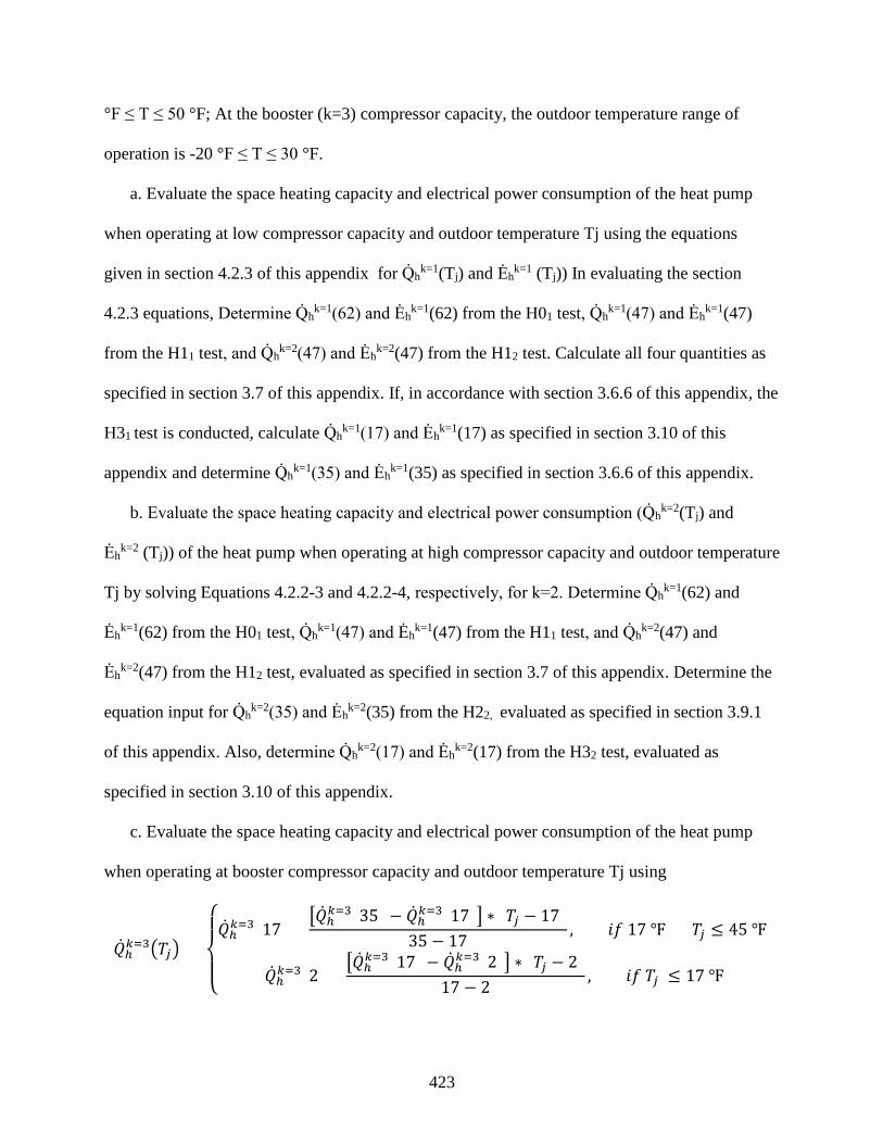
423
°F ≤ T ≤ 50 °F; At the booster (k=3) compressor capacity, the outdoor temperature range of
operation is -20 °F ≤ T ≤ 30 °F.
a. Evaluate the space heating capacity and electrical power consumption of the heat pump
when operating at low compressor capacity and outdoor temperature Tj using the equations
given in section 4.2.3 of this appendix for Q̇hk=1(Tj) and Ėh
k=1 (Tj)) In evaluating the section
4.2.3 equations, Determine Q̇hk=1(62) and Ėh
k=1(62) from the H01 test, Q̇hk=1(47) and Ėh
k=1(47)
from the H11 test, and Q̇hk=2(47) and Ėh
k=2(47) from the H12 test. Calculate all four quantities as
specified in section 3.7 of this appendix. If, in accordance with section 3.6.6 of this appendix, the
H31 test is conducted, calculate Q̇hk=1(17) and Ėh
k=1(17) as specified in section 3.10 of this
appendix and determine Q̇hk=1(35) and Ėh
k=1(35) as specified in section 3.6.6 of this appendix.
b. Evaluate the space heating capacity and electrical power consumption (Q̇hk=2(Tj) and
Ėhk=2 (Tj)) of the heat pump when operating at high compressor capacity and outdoor temperature
Tj by solving Equations 4.2.2-3 and 4.2.2-4, respectively, for k=2. Determine Q̇hk=1(62) and
Ėhk=1(62) from the H01 test, Q̇h
k=1(47) and Ėhk=1(47) from the H11 test, and Q̇h
k=2(47) and
Ėhk=2(47) from the H12 test, evaluated as specified in section 3.7 of this appendix. Determine the
equation input for Q̇hk=2(35) and Ėh
k=2(35) from the H22, evaluated as specified in section 3.9.1
of this appendix. Also, determine Q̇hk=2(17) and Ėh
k=2(17) from the H32 test, evaluated as
specified in section 3.10 of this appendix.
c. Evaluate the space heating capacity and electrical power consumption of the heat pump
when operating at booster compressor capacity and outdoor temperature Tj using
�̇�𝑄ℎ𝑘𝑘=3�𝑇𝑇𝑗𝑗� =
⎩⎪⎨
⎪⎧�̇�𝑄ℎ𝑘𝑘=3(17) +
��̇�𝑄ℎ𝑘𝑘=3(35) − �̇�𝑄ℎ𝑘𝑘=3(17)� ∗ (𝑇𝑇𝑗𝑗 − 17)35 − 17
, 𝑠𝑠𝑓𝑓 17 ℉ < 𝑇𝑇𝑗𝑗 ≤ 45 ℉
�̇�𝑄ℎ𝑘𝑘=3(2) +��̇�𝑄ℎ𝑘𝑘=3(17) − �̇�𝑄ℎ𝑘𝑘=3(2)� ∗ (𝑇𝑇𝑗𝑗 − 2)
17 − 2, 𝑠𝑠𝑓𝑓 𝑇𝑇𝑗𝑗 ≤ 17 ℉

424
�̇�𝐸ℎ𝑘𝑘=3�𝑇𝑇𝑗𝑗�
=
⎩⎪⎨
⎪⎧�̇�𝐸ℎ𝑘𝑘=3(17) +
��̇�𝐸ℎ𝑘𝑘=3(35) − �̇�𝐸ℎ𝑘𝑘=3(17)� ∗ (𝑇𝑇𝑗𝑗 − 17)35 − 17
, 𝑠𝑠𝑓𝑓 17 ℉ < 𝑇𝑇𝑗𝑗 ≤ 45 ℉
�̇�𝐸ℎ𝑘𝑘=3(2) +��̇�𝐸ℎ𝑘𝑘=3(17) − �̇�𝐸ℎ𝑘𝑘=3(2)� ∗ (𝑇𝑇𝑗𝑗 − 2)
17 − 2, 𝑠𝑠𝑓𝑓 𝑇𝑇𝑗𝑗 ≤ 17 ℉
Determine Q̇hk=3(17) and Ėh
k=3(17) from the H33 test and determine Q̇hk=2(2) and Ėh
k=3(2) from
the H43 test. Calculate all four quantities as specified in section 3.10 of this appendix. Determine
the equation input for Q̇hk=3(35) and Ėh
k=3(35) as specified in section 3.6.6 of this appendix.
4.2.6.1 Steady-state space heating capacity when operating at low compressor capacity is greater
than or equal to the building heating load at temperature Tj, Q̇hk=1(Tj) ≥BL(Tj)., and the heat
pump permits low compressor capacity at Tj.
Evaluate the quantities
𝐸𝐸𝑅𝑅�𝑇𝑇𝑗𝑗�𝑁𝑁
and 𝑑𝑑ℎ�𝑇𝑇𝑗𝑗�𝑁𝑁
using Eqs. 4.2.3-1 and 4.2.3-2, respectively. Determine the equation inputs Xk=1(Tj), PLFj, and
δ′(Tj) as specified in section 4.2.3.1 of this appendix. In calculating the part load factor, PLFj ,
use the low-capacity cyclic-degradation coefficient CDh, [or equivalently, CD
h(k=1)] determined
in accordance with section 3.6.6 of this appendix.
4.2.6.2 Heat pump only operates at high (k=2) compressor capacity at temperature Tj and its
capacity is greater than or equal to the building heating load, BL(Tj) <Q̇hk=2(Tj).
Evaluate the quantities
𝐸𝐸𝑅𝑅�𝑇𝑇𝑗𝑗�𝑁𝑁
and 𝑑𝑑ℎ�𝑇𝑇𝑗𝑗�𝑁𝑁
as specified in section 4.2.3.3 of this appendix. Determine the equation inputs Xk=2(Tj), PLFj ,
and δ′(Tj) as specified in section 4.2.3.3 of this appendix. In calculating the part load factor,
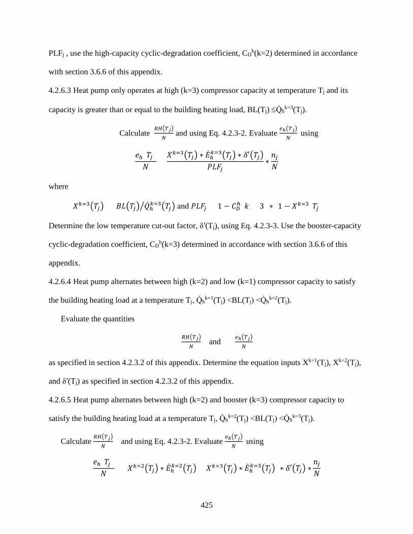
425
PLFj , use the high-capacity cyclic-degradation coefficient, CDh(k=2) determined in accordance
with section 3.6.6 of this appendix.
4.2.6.3 Heat pump only operates at high (k=3) compressor capacity at temperature Tj and its
capacity is greater than or equal to the building heating load, BL(Tj) ≤Q̇hk=3(Tj).
Calculate 𝐸𝐸𝑅𝑅�𝑇𝑇𝑗𝑗�
𝑁𝑁 and using Eq. 4.2.3-2. Evaluate
𝑑𝑑ℎ�𝑇𝑇𝑗𝑗�𝑁𝑁
using
𝑆𝑆ℎ(𝑇𝑇𝑗𝑗)𝑁𝑁
=𝑋𝑋𝑘𝑘=3�𝑇𝑇𝑗𝑗� ∗ �̇�𝐸ℎ𝑘𝑘=3�𝑇𝑇𝑗𝑗� ∗ 𝛿𝛿′�𝑇𝑇𝑗𝑗�
𝑃𝑃𝑈𝑈𝑁𝑁𝑗𝑗∗𝑛𝑛𝑗𝑗𝑁𝑁
where
𝑋𝑋𝑘𝑘=3�𝑇𝑇𝑗𝑗� = 𝐵𝐵𝑈𝑈�𝑇𝑇𝑗𝑗� �̇�𝑄ℎ𝑘𝑘=3�𝑇𝑇𝑗𝑗�� and 𝑃𝑃𝑈𝑈𝑁𝑁𝑗𝑗 = 1 − 𝑈𝑈𝐷𝐷ℎ(𝑘𝑘 = 3) ∗ [1 − 𝑋𝑋𝑘𝑘=3(𝑇𝑇𝑗𝑗)
Determine the low temperature cut-out factor, δ′(Tj), using Eq. 4.2.3-3. Use the booster-capacity
cyclic-degradation coefficient, CDh(k=3) determined in accordance with section 3.6.6 of this
appendix.
4.2.6.4 Heat pump alternates between high (k=2) and low (k=1) compressor capacity to satisfy
the building heating load at a temperature Tj, Q̇hk=1(Tj) <BL(Tj) <Q̇h
k=2(Tj).
Evaluate the quantities
𝐸𝐸𝑅𝑅�𝑇𝑇𝑗𝑗�𝑁𝑁
and 𝑑𝑑ℎ�𝑇𝑇𝑗𝑗�𝑁𝑁
as specified in section 4.2.3.2 of this appendix. Determine the equation inputs Xk=1(Tj), Xk=2(Tj),
and δ′(Tj) as specified in section 4.2.3.2 of this appendix.
4.2.6.5 Heat pump alternates between high (k=2) and booster (k=3) compressor capacity to
satisfy the building heating load at a temperature Tj, Q̇hk=2(Tj) <BL(Tj) <Q̇h
k=3(Tj).
Calculate 𝐸𝐸𝑅𝑅�𝑇𝑇𝑗𝑗�
𝑁𝑁 and using Eq. 4.2.3-2. Evaluate
𝑑𝑑ℎ�𝑇𝑇𝑗𝑗�𝑁𝑁
using
𝑆𝑆ℎ(𝑇𝑇𝑗𝑗)𝑁𝑁
= [𝑋𝑋𝑘𝑘=2�𝑇𝑇𝑗𝑗� ∗ �̇�𝐸ℎ𝑘𝑘=2�𝑇𝑇𝑗𝑗� + 𝑋𝑋𝑘𝑘=3�𝑇𝑇𝑗𝑗� ∗ �̇�𝐸ℎ𝑘𝑘=3�𝑇𝑇𝑗𝑗�] ∗ 𝛿𝛿′�𝑇𝑇𝑗𝑗� ∗𝑛𝑛𝑗𝑗𝑁𝑁

426
where:
𝑋𝑋𝑘𝑘=2�𝑇𝑇𝑗𝑗� =�̇�𝑄ℎ𝑘𝑘=3�𝑇𝑇𝑗𝑗� − 𝐵𝐵𝑈𝑈(𝑇𝑇𝑗𝑗)�̇�𝑄ℎ𝑘𝑘=3�𝑇𝑇𝑗𝑗� − �̇�𝑄ℎ𝑘𝑘=2�𝑇𝑇𝑗𝑗�
and Xk=3(Tj) = Xk=2(Tj) = the heating mode, booster capacity load factor for temperature bin j,
dimensionless. Determine the low temperature cut-out factor, δ′(Tj), using Eq. 4.2.3-3.
4.2.6.6 Heat pump only operates at low (k=1) capacity at temperature Tj and its capacity is less
than the building heating load, BL(Tj) > Q̇hk=1(Tj).
𝑑𝑑ℎ(𝑇𝑇𝑗𝑗)𝑁𝑁
= �̇�𝐸ℎ𝑘𝑘=1�𝑇𝑇𝑗𝑗� ∗ 𝛿𝛿′�𝑇𝑇𝑗𝑗� ∗𝑛𝑛𝑗𝑗𝑁𝑁
and 𝐸𝐸𝑅𝑅(𝑇𝑇𝑗𝑗)
𝑁𝑁= 𝐵𝐵𝑃𝑃�𝑇𝑇𝑗𝑗�−[�̇�𝑄ℎ
𝑘𝑘=1�𝑇𝑇𝑗𝑗�∗𝛿𝛿′�𝑇𝑇𝑗𝑗�]
3.413𝐵𝐵𝑓𝑓𝐵𝐵 ℎ⁄𝑊𝑊
∗ 𝑛𝑛𝑗𝑗𝑁𝑁
where the low temperature cut-out factor, δ′(Tj), is calculated using Eq. 4.2.3–3.
4.2.6.7 Heat pump only operates at high (k = 2) capacity at temperature Tj and its capacity is less
than the building heating load, BL(Tj) > Q̇hk=2(Tj).
Evaluate the quantities
𝐸𝐸𝑅𝑅�𝑇𝑇𝑗𝑗�𝑁𝑁
and 𝑑𝑑ℎ�𝑇𝑇𝑗𝑗�𝑁𝑁
as specified in section 4.2.3.4 of this appendix. Calculate δ″(Tj) using the equation given
in section 4.2.3.4 of this appendix.
4.2.6.8 Heat pump only operates at booster (k = 3) capacity at temperature Tj and its capacity is
less than the building heating load, BL(Tj) > Q̇hk=3(Tj) or the system converts to using only
resistive heating.
𝑑𝑑ℎ(𝑇𝑇𝑗𝑗)𝑁𝑁
= �̇�𝐸ℎ𝑘𝑘=3�𝑇𝑇𝑗𝑗� ∗ 𝛿𝛿′�𝑇𝑇𝑗𝑗� ∗𝑛𝑛𝑗𝑗𝑁𝑁
and 𝐸𝐸𝑅𝑅(𝑇𝑇𝑗𝑗)
𝑁𝑁= 𝐵𝐵𝑃𝑃�𝑇𝑇𝑗𝑗�−[�̇�𝑄ℎ
𝑘𝑘=3�𝑇𝑇𝑗𝑗�∗𝛿𝛿′�𝑇𝑇𝑗𝑗�]
3.413𝐵𝐵𝑓𝑓𝐵𝐵 ℎ⁄𝑊𝑊
∗ 𝑛𝑛𝑗𝑗𝑁𝑁
where δ″(Tj) is calculated as specified in section 4.2.3.4 of this appendix if the heat pump is
operating at its booster compressor capacity. If the heat pump system converts to using only
resistive heating at outdoor temperature Tj , set δ′(Tj) equal to zero.
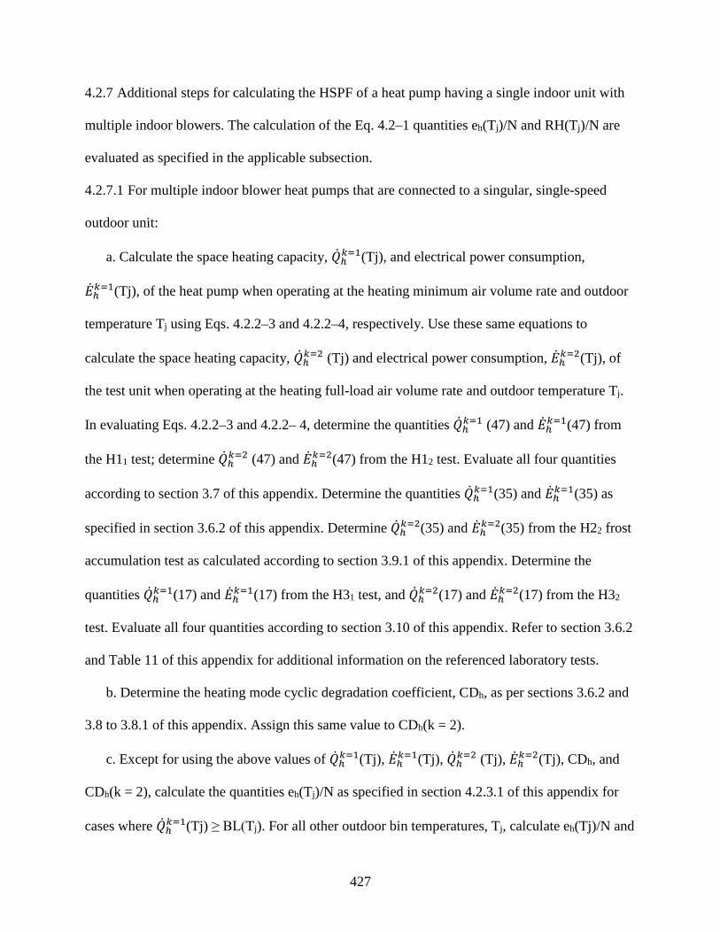
427
4.2.7 Additional steps for calculating the HSPF of a heat pump having a single indoor unit with
multiple indoor blowers. The calculation of the Eq. 4.2–1 quantities eh(Tj)/N and RH(Tj)/N are
evaluated as specified in the applicable subsection.
4.2.7.1 For multiple indoor blower heat pumps that are connected to a singular, single-speed
outdoor unit:
a. Calculate the space heating capacity, �̇�𝑄ℎ𝑘𝑘=1(Tj), and electrical power consumption,
�̇�𝐸ℎ𝑘𝑘=1(Tj), of the heat pump when operating at the heating minimum air volume rate and outdoor
temperature Tj using Eqs. 4.2.2–3 and 4.2.2–4, respectively. Use these same equations to
calculate the space heating capacity, �̇�𝑄ℎ𝑘𝑘=2 (Tj) and electrical power consumption, �̇�𝐸ℎ𝑘𝑘=2(Tj), of
the test unit when operating at the heating full-load air volume rate and outdoor temperature Tj.
In evaluating Eqs. 4.2.2–3 and 4.2.2– 4, determine the quantities �̇�𝑄ℎ𝑘𝑘=1 (47) and �̇�𝐸ℎ𝑘𝑘=1(47) from
the H11 test; determine �̇�𝑄ℎ𝑘𝑘=2 (47) and �̇�𝐸ℎ𝑘𝑘=2(47) from the H12 test. Evaluate all four quantities
according to section 3.7 of this appendix. Determine the quantities �̇�𝑄ℎ𝑘𝑘=1(35) and �̇�𝐸ℎ𝑘𝑘=1(35) as
specified in section 3.6.2 of this appendix. Determine �̇�𝑄ℎ𝑘𝑘=2(35) and �̇�𝐸ℎ𝑘𝑘=2(35) from the H22 frost
accumulation test as calculated according to section 3.9.1 of this appendix. Determine the
quantities �̇�𝑄ℎ𝑘𝑘=1(17) and �̇�𝐸ℎ𝑘𝑘=1(17) from the H31 test, and �̇�𝑄ℎ𝑘𝑘=2(17) and �̇�𝐸ℎ𝑘𝑘=2(17) from the H32
test. Evaluate all four quantities according to section 3.10 of this appendix. Refer to section 3.6.2
and Table 11 of this appendix for additional information on the referenced laboratory tests.
b. Determine the heating mode cyclic degradation coefficient, CDh, as per sections 3.6.2 and
3.8 to 3.8.1 of this appendix. Assign this same value to CDh(k = 2).
c. Except for using the above values of �̇�𝑄ℎ𝑘𝑘=1(Tj), �̇�𝐸ℎ𝑘𝑘=1(Tj), �̇�𝑄ℎ𝑘𝑘=2 (Tj), �̇�𝐸ℎ𝑘𝑘=2(Tj), CDh, and
CDh(k = 2), calculate the quantities eh(Tj)/N as specified in section 4.2.3.1 of this appendix for
cases where �̇�𝑄ℎ𝑘𝑘=1(Tj) ≥ BL(Tj). For all other outdoor bin temperatures, Tj, calculate eh(Tj)/N and

428
RHh(Tj)/N as specified in section 4.2.3.3 of this appendix if �̇�𝑄ℎ𝑘𝑘=2(Tj) > BL(Tj) or as specified in
section 4.2.3.4 of this appendix if �̇�𝑄ℎ𝑘𝑘=2(Tj) ≤ BL(Tj)
4.2.7.2 For multiple indoor blower heat pumps connected to either a single outdoor unit with a
two-capacity compressor or to two separate single-speed outdoor units of identical model,
calculate the quantities eh(Tj)/N and RH(Tj)/N as specified in section 4.2.3 of this appendix.
4.3 Calculations of Off-mode Power Consumption.
For central air conditioners and heat pumps with a cooling capacity of:
less than 36,000 Btu/h, determine the off mode represented value, 𝑃𝑃𝑊𝑊,𝐶𝐶𝐹𝐹𝐹𝐹, with the following
equation:
𝑃𝑃𝑊𝑊,𝐶𝐶𝐹𝐹𝐹𝐹 = 𝑃𝑃1 + 𝑃𝑃2
2;
greater than or equal to 36,000 Btu/h, calculate the capacity scaling factor according to:
𝑁𝑁𝑠𝑠𝑐𝑐𝑉𝑉𝑓𝑓𝑑𝑑 = �̇�𝑄𝐶𝐶(95)36,000
,
where �̇�𝑄𝐶𝐶(95) is the total cooling capacity at the A or A2 test condition, and determine the
off mode represented value, 𝑃𝑃𝑊𝑊,𝐶𝐶𝐹𝐹𝐹𝐹, with the following equation:
𝑃𝑃𝑊𝑊,𝐶𝐶𝐹𝐹𝐹𝐹 = 𝑃𝑃1 + 𝑃𝑃2
2 × 𝑁𝑁𝑠𝑠𝑐𝑐𝑉𝑉𝑓𝑓𝑑𝑑;
4.4 Rounding of SEER and HSPF for reporting purposes.
After calculating SEER according to section 4.1 of this appendix and HSPF according to
section 4.2 of this appendix round the values off as specified per §430.23(m) of title 10 of the
Code of Federal Regulations.

429
Figure 1—Heating Load Hours (HLHA) for the United States
Figure 2—Cooling Load Hours (CLHA) for the United States
Table 21 Representative Cooling and Heating Load Hours for Each Generalized Climatic Region
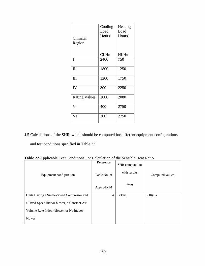
430
Climatic Region
Cooling Load Hours
CLHR
Heating Load Hours
HLHR
I 2400 750
II 1800 1250
III 1200 1750
IV 800 2250
Rating Values 1000 2080
V 400 2750
VI 200 2750
4.5 Calculations of the SHR, which should be computed for different equipment configurations
and test conditions specified in Table 22.
Table 22 Applicable Test Conditions For Calculation of the Sensible Heat Ratio
Equipment configuration
Reference
Table No. of
Appendix M
SHR computation
with results
from
Computed values
Units Having a Single-Speed Compressor and
a Fixed-Speed Indoor blower, a Constant Air
Volume Rate Indoor blower, or No Indoor
blower
4 B Test SHR(B)

431
Units Having a Single-Speed Compressor That
Meet the section 3.2.2.1 Indoor Unit
Requirements
5 B2 and B1 Tests SHR(B1), SHR(B2)
Units Having a Two-Capacity Compressor 6 B2 and B1 Tests SHR(B1), SHR(B2)
Units Having a Variable-Speed Compressor 7 B2 and B1 Tests SHR(B1), SHR(B2)
The SHR is defined and calculated as follows:
𝑁𝑁𝐻𝐻𝐸𝐸 =𝑁𝑁𝑆𝑆𝑛𝑛𝑠𝑠𝑠𝑠𝑠𝑠𝑙𝑙𝑆𝑆 𝑈𝑈𝑜𝑜𝑜𝑜𝑙𝑙𝑠𝑠𝑛𝑛𝑠𝑠 𝑈𝑈𝑎𝑎𝐶𝐶𝑎𝑎𝑠𝑠𝑠𝑠𝑡𝑡𝐶𝐶𝑇𝑇𝑜𝑜𝑡𝑡𝑎𝑎𝑙𝑙 𝑈𝑈𝑜𝑜𝑜𝑜𝑙𝑙𝑠𝑠𝑛𝑛𝑠𝑠 𝑈𝑈𝑎𝑎𝐶𝐶𝑎𝑎𝑠𝑠𝑠𝑠𝑡𝑡𝐶𝐶
=�̇�𝑄𝑠𝑠𝑐𝑐𝑘𝑘 (𝑇𝑇)�̇�𝑄𝑐𝑐𝑘𝑘(𝑇𝑇)
Where both the total and sensible cooling capacities are determined from the same cooling
mode test and calculated from data collected over the same 30-minute data collection interval.
4.6 Calculations of the Energy Efficiency Ratio (EER). Calculate the energy efficiency ratio
using,
𝐸𝐸𝐸𝐸𝐸𝐸 =𝑇𝑇𝑜𝑜𝑡𝑡𝑎𝑎𝑙𝑙 𝑈𝑈𝑜𝑜𝑜𝑜𝑙𝑙𝑠𝑠𝑛𝑛𝑠𝑠 𝑈𝑈𝑎𝑎𝐶𝐶𝑎𝑎𝑠𝑠𝑠𝑠𝑡𝑡𝐶𝐶
𝑇𝑇𝑜𝑜𝑡𝑡𝑎𝑎𝑙𝑙 𝐸𝐸𝑙𝑙𝑆𝑆𝑠𝑠𝑡𝑡𝑟𝑟𝑠𝑠𝑠𝑠𝑎𝑎𝑙𝑙 𝑃𝑃𝑜𝑜𝑃𝑃𝑆𝑆𝑟𝑟 𝑈𝑈𝑜𝑜𝑛𝑛𝑠𝑠𝐵𝐵𝑠𝑠𝐶𝐶𝑡𝑡𝑠𝑠𝑜𝑜𝑛𝑛
=�̇�𝑄𝑐𝑐𝑘𝑘(𝑇𝑇)�̇�𝐸𝑐𝑐𝑘𝑘(𝑇𝑇)
where �̇�𝑄𝑐𝑐𝑘𝑘(𝑇𝑇) and �̇�𝐸𝑐𝑐𝑘𝑘(𝑇𝑇) are the space cooling capacity and electrical power consumption
determined from the 30-minute data collection interval of the same steady-state wet coil cooling
mode test and calculated as specified in section 3.3 of this appendix. Add the letter identification
for each steady-state test as a subscript (e.g., 𝐸𝐸𝐸𝐸𝐸𝐸𝐴𝐴2) to differentiate among the resulting EER
values.