this document has been reproduced from … · selected aca concept and materials 2-9 dynamic...
TRANSCRIPT

N O T I C E
THIS DOCUMENT HAS BEEN REPRODUCED FROM MICROFICHE. ALTHOUGH IT IS RECOGNIZED THAT
CERTAIN PORTIONS ARE ILLEGIBLE, IT IS BEING RELEASED IN THE INTEREST OF MAKING AVAILABLE AS MUCH
INFORMATION AS POSSIBLE
https://ntrs.nasa.gov/search.jsp?R=19800009838 2018-05-27T10:07:19+00:00Z

If
MR a
i
l!1 CONTRACT NAS1-15069
Advanced Composite AileronFor L-1011 Transport Aircraft
,DLR 003
QUARTERLY TECHNICAL REPORT - NO. 2
This report is for the period 22 December 1973 through 24 March 1978
Lockheed CorporationLockheed-California Company
Post Office Box. 551Burbank, California 91520
(NASA-CR-lb2663) ADVANCED COMFOR L-1011 TFANSi;GET A ILI CRAFTTechaicdl Report, 21 Dec. 19731978 (Lock heed-c.dli forma Co.,
r 54 p HC A04/MF A01
POSITE AILch0N N8J-18103^uacteriy24 Ndl.
Blirbar i k.) OnclasC:>CL 1 1 C ;-J/24 3s566
I.
14 April 1978
Prepared for Langley Research Center
A"J
1918 dN\
INJ ` _RS t^v"^L1T1 vim'
^s^ ► c 7.11^v '^^ 9 5 h 4ti
,I

.1
LR 28559
CONTRACT NAS1-15069
Advanced Composite AileronFor L-1011 Transport Aircraft
DLR 003
QUARTERLY TECHNICAL REPORT — NO.
This report is for the period 22 December 1973 through 24 March 1978
Lockheed Corporation
Lockheed-California CompanyPost Office Box 551
Burbank, California 91520
Approved By. ^ JF.C. EnglishProgram Manager
14 April 1978
Prepared for Langley Research Center

Page intentionally left blank

LR 28559
FOREWORD
This report was prepared by the Lockheed-California Company, Lockheed
Corporation, Burbank, California, under contract NAS1-15069. It is the second
quarterly technical report covering work completed between 22 December 1977
and 24 March 1978. The program is sponsored by the National Aeronautics and
Space Administration (NASA), Langley Research Center. The Program Manager
for Lockheed is Mr. Fred C. English. Mr- Louis F. Vosteen is Project Manager
for NASA, Langley. The Technical Representative for NASA, Langley is
Mr. Herman L. Bohon.
LOCKHEEDf.JtiIAM N^. COY /.N^

Page intentionally left blank

LR 28559
SUMMARY
The activities performed in this reporting period end documented in this
report are associated with Task I - Engineering Development, and Task II -
Design and Analysis of the Advanced Composite Aileron (ACA) program. Task I
activities included the completion of design assessment and material evalua-
tion. The ae f:ail deign of the aileron has been initiated as part of Task II.
Design and evaluation of alternate concepts for the major subcomponents
of the ACA was completed. From this array of subcomponents aileron assemblies
were formulated and evaluated. Based on these analyses a multirib assembly
with graphite tape/syntactic core covers, a graphite tape front spar, and a
graphite fabric ribs was selected for development in the remainder of the ACA
program. A weight savings of 29.1% (40.8 pounds per aileron) is currently
being predicted for the ACA. Engineering cost anaiyoes indicate that the pro-
duction cost of the ACA will be 7.3% less than the current aluminum aileron.
Fabrication, machining, and testing of the material evaluation specimens
for the resin screening program was completed at Lockheed-California Company
and Avco. These test results lead to the selection of Narmco 5208 resin for
the ACA.
Task II activities initiated during this reportin g quarter include the
detail design of the ACA, construction of a three-dimensional finite element
model for structural analysis, and formulation of detail plans for material
verification and process development.
I
v
LOCKHEEDCw^i.ONrai^ CJUNwNr

Page intentionally left blank

LR 28559
TABLE OF CONTENTS
FOREWORD
SUMMARY
LIST OF FIGURES
LIST OF TABLES
INTRODUCTION
TASK I - ENGINEERING DEVELOPMENT, DESIGN ASSESSMENT
ALTERNATE CONCiPTS
Rib Backup Fittings
Main Ribs
Aileron Assembly
Concept/Materials Interactive Study
SELECTED ACA DESIGN CONCEPT
TASK 1 - ENGINEERING DEVELOPMENT, MATERIAL EVALUATION
STRUCTURAL SCREENINGS TESTS
PRODUCIBILITY SCREENING TESTS
SELECTED MATERIALS
:ASK II - DESIGN AND ANALYSIS, COMPONENT DEFINITION
DETAIL DESIGN
STRUCTURAL ANALYSIS
NASTRAN Model
Development of Material Verification Test Plans
Weight Status
MATERIALS AND PRODUCIBILITY ANALYSIS
TASK II - DESIGN AND ANALYSIS, PROCESS DEVELOPMENT ANDVERIFICATION
PROCESS DEVELOPMENT
REFERENCES
Section
1
2
2.1
2.1.1
2.1.2
2.1.3
2.1.4
2.2
3
3.1
3.2
3.3
4
4.1
4.2
4.2.1
4.2.2
4.2.3
4.3
5
5.1
Page
iii
v
ix
xi
1-1
2-1
2-1
2-1
2-2
2-3
2-4
2-8
3-1
3-1
3-12
3-13
4-1
4-1
4-1
4-1
4-2
4-9
4-9
5-1
5-1
R-1
viiLOCKHEEDC.LIIOM A Co.:-

Page intentionally left blank

LR 28559
LIST OF FIGURES
Page
Advanced Composite Aileron - Program Master Schedule 1-2
Aluminum Diefcrged Hinge and Actuator Fitting 2-3
L-1011 Inboard Aileron Concept No. 1 2-5
L-1021 Inboard Aileron Concept No. 2 2-6
Selected ACA Concept and Materials 2-9
Dynamic Flexure Test Results 3-11
Male Tool Rubber Bag 3-17
Female Tool Rubber Bag 3-17
ACA Basic Design Drawing 4-3
Composite Aileron Finite Element Kodel 4-7
Actuator and Hinge Support Stations 4-8
Weight Time History 4-12
Figure
1-1
2-1
2-2
2-3
2-4
3-1
3-2
3-3
4-1
4-2
4-3
4-4
ixLOCKHEEDCALIFORNIA COMOANY

Page intentionally left blank

Page
Rib Backup Fitting Evaluation Matrix 2-2
Main Rib Evaluation Matrix 2-4
Aileron Assembly Evaluation Matrix 2-7
Concept/Materials Refinement 2-8
Composite Aileron: Weight Breakdown 2-10
Quantitative Screening Tests for Combinations ofResins and Reinforcements 3-2
Process Development for Structural Screening -Syntactic and Honeycomb 3-4
Structural Screening Test Panels 3-5
Material Screening - Solid Laminate Test Results 3-7
Material Screening of Graphite/Syntactic -Summary of Test Results 3-8
Material Screening of honeycomb Sandwich Test Specimens 3-9
Ranking of Quantitative Screening Test Results 3-10
Materials Producibility Evaluations 3-13
Producibility Evaluations - Specimen Test Results 3-15
Weight Status Report 4-10
Summary of Weight Changes 4-11
Table
2-1
2-2
2-3
2-4
2-5
3-1
3-2
3-3
3-4
3-5
3-6
3-7
3-8
3-9
4-1
4-2
LR 28559
LIST OF TABLES
xiLOCKHEEDC 1ron NI& COMPAN,

LQ 28559
SECTION 1
INTRODUCTION
The broad objective of NASA's Aircraft Energy Efficiency (ACEE) Compo-
site Structures Program is to accelerate the use of composite materials in
aircraft structures by developing technology for early introduction of struc-
tures made of these materials into commercial transport aircraft. This pro-
gram, one of several which are collectively aimed toward accomplishing the
broad objective, has the specific goal to demonstrate the weight and cost-
saving nw-ential of secondary structures constructed of advanced composite
materials. The secondary structure selected for the program is the inboard
aileron of the Lockheed L-1011 aircraft.
The scope of this program is to design, fabricate, qualify, and certifi-
cate a composite inboard aileron; to test selected subcomponents to verify
the design; to fabricate and test two ground test articles; to fabricate and
install ten shipsets of inboard ailerons; and to gather flight service data
on the ten shipsets of composite ailerons.
The Lockheed-California Company is teamed with Avco Aerostructures Divi-
sion of Avco Corporation. Lockheed will design the aileron, conduct the ma-
terials, concept verification, and ground tests, and evaluate in-flight
service experience. Avco will develop manufacturing processes, fabricate
test specimens, and fabricate the ground test and flight articles.
As shown on the master schedule, Figure 1-1, the program will be con-
ducted in six consequential tasks. Task I, Engineering Development, and Task
II, Design and Analysis, are the portions of the program wherein the compo-
site aileron design will be formulated and subcomponents fabricated and
tested to verify design concepts and fabrication procedures. During Task
# III, Manufacturing Development, and Task IV, Ground Test and Flight Checkout,r
I
LOCKHEED 1-1C^l1IOM N^• COM..Nv
1

S
a
f ,.
.f.
N
a^
n
1-2II
LOCKHEEDCALIPOMN IA COMPANY ORIGINAL PAGE 19
OF POOR QUA.LUM
4'
LR 28559
^d
n'1 I,
11 1
^ N ^N 11
I1
N 11
1'I
_ ^_I1
4 < Np p 'u ^ u u
11
11
I 11
1
D AD (^ 1^1
1I
1 1
1
1
1
1 1
1 1
1 1
1 I
1 1
1
1 11 I
1 1
1 I
1 1
1
1 1
1 1
1 I
1 1
1 ^
^ I1
.............................. ^..e1 = <
1
1 ^ rI
I
I1 I
1
1
I
1
1
I
I
1
1
1 1
d
d
uHi+d
^HH
^dF+WOwa
^^1
F+
O}.10
LI
N
OpU10du
bQ
I-^
{•Ipto71W
7z
D
D
0
PAPA...: ^
f J
i >
1t ^'
o ^'
oD
a., 1 1
1 1....................................1..........................................a...................!
1 1Q 1 1
a o ^ IF ^ 1 ; i r
aJ '
J 5 z oa
1 NI `- o-
WV
.c r .t I >< I
. I

LR 28559
production quality manufacturing tools will be constructed, ;Vnd t%V full-
scale ailerons will be fabricated and tested. A ?roduction run ten (10)
shipsets will be fabricated during Task V, Aileron Manufacture, to provide
manufacturing and cost information. In Task VI, Plight Service, inspection
and maintenance data will be gathered on the ten shipsets of ailerons to dem-
onstrate that they can be economically operated in routine service. The work
performed during this program is intended to provide the data required to
progress toward a production commitment.
This report describes work accomplished during the second three-month
period of the program. The two principal subtasks within Task 1 of the ACA
program are design assessment and materials evaluation. Activities within
these subtasks which have been completed during this reporting period are
documented in Sections 2 and 3, respectively. Task II of the program has
been initiated. Engineering and planning efforts during this reporting
period are discuFied in Sections 4 and 5.
LOCKHEED 1"3C.L I. 0 11N - . COMP.-'

F
LR 28559
SECTION 2
TASK I - ENGINEERING DEVELOPMENT, DESIGN ASSESSMENT
The objective of the design assessment subtask within Task I was to
select a design concept for the ACA with the greatest potential for meeting
the program objectives. The approach used for this activity was to define
the design criteria, develop alternate designs, evaluate the alternatives
against the cost and weight objectives, and select the best alternative.
Design criteria and several of the alternate concepts for the subcomponents
of the ACA were discussed in Quarterly Report Nu:.iber 1 (Reference 1). The
remainder of the subcomponent alternate concepts, the assembly evaluation,
and the selected design for the ACA are presented in the following
paragraphs.
2.1 ALTERNATE CONCEPTS
Alternate concepts were designed and evaluated for covers, front and
rear spars, main and intermediate ribs, and rib backup fittings. Combinations
of these subcomponents were then assembled and these assemblies evaluated
to ma;:e the final concept selection. The design and evaluation of the covers,
spars, and ribs was reported in Quarterly Technical Report No. 1 (Reference 1).
During this reporting period the evaluation of the rib backup fittings, the
main ribs with the backup fittings included, and the aileron assemblies was
completed.
2.1.1 Rib Backup Fittings
Three designs for the rib backup fitting were evaluated; a graphite tape
bathtub, a graphite fabric bathtub, and a dieforged aluminum bathtub. The
evaluation matrix for the rib backup fitting is shown in Table 2-1. As a
LOCKHEED 2-1cAuroft— A COUP-

LR 28559
TABLE 2-1. RIB BACKUP FITTING EVALUATION MATRIX
COMPONENT BACK-UP FITTING
CONCEPT BATHTUB
MATERIAL ALUMINUM #3 GR — TAPE /1 GR — CLOTH 82
Weight (lb) 0.70 0.48 0.52
Cost Ratio 0.18 1.00 1.07
Tooling andManufacturingProcesses Good Poor Poor
Inspectability Good Fair Fair
ImpactResistance Good Good Good
EnvironmentalSensitivity Fair Good Good
Haintainability Fair Fair Fair
Repairability Nct applicable O Not applicable O Not applicable `3
Remarks r(D Replace Fitting Ol Replace Fitting `" Replace Fitting
consequence of its very low cost as compared to the composite designs, the
dieforged aluminum fitting was selected for the assemblies. A drawing of
this part is shown in Figure 2-1.
2.1.2 Main Ribs
The main rib designs and their evaluation were discussed in Quarterly
Technical Report No. 1 (Reference 1). Three main ribs are included in the
aileron assembly. The main ribs at 1AS 57 and IAS 102 are connected to hinge/
actuator fittings through the spar web. The main rib at IAS 107 is connected
to an actuator fitting. Rib backup fittings are used to facilitate trans-
mission of the concentrated loads from the rib web and caps. The rib backup
fitting in the current metal aileron is a full-depth fitting designed to
LOCKHEED2-2
CPf ".'. cow /yM•
11v

3.10
>--2.50
^ .90l
70751'6 DIE FORGING
LR 28559
e
Figure 2-4. Aluminum Dieforged Hinge and Actuator Backup Fitting
(All dimensions shown in inches)
transmit the rib web shear as well as the rij cap loads. Two of these fittings
nre required per main rib. For the composite designs, the aluminum bathtub
fitting was selected, since the composite rib web is flanged ac the spar inter-
face to transmit the web shear. Four bathtuL fittings are required for the
composite main ribs at IAS 57 and IAS 102, and three are used at IAS 107. A
comparison of a typical aluminum main rib subassembly with the composite main
rib designs is shown in Table 2-2. Concepts ail and #2 were selected for evalua-
tion in assemblies because of their low cost and weight compared Co the other
designs which were evaluated.
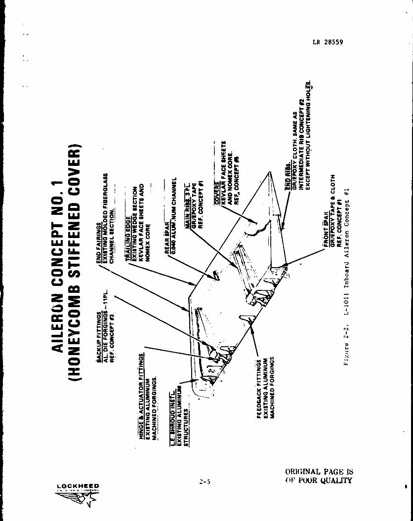
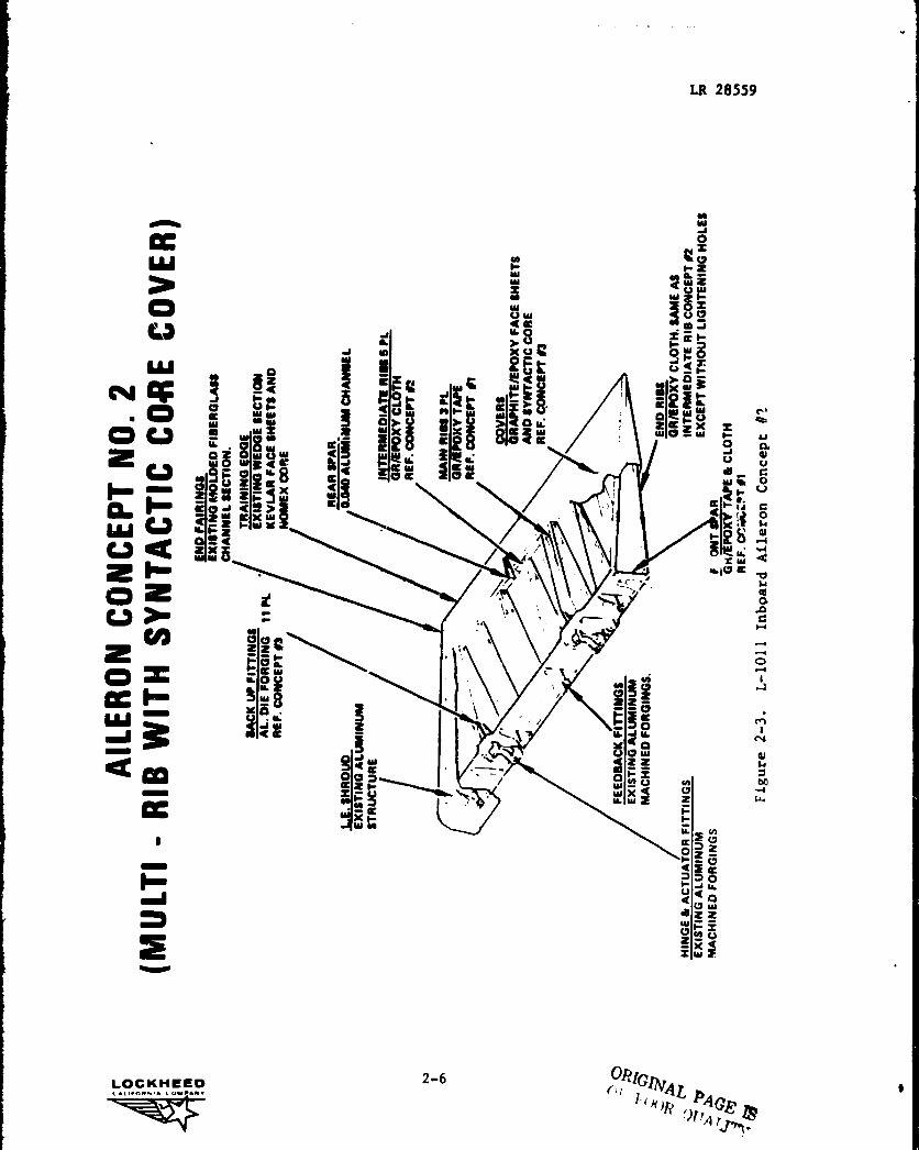
2.1.3 Aileron Assembly
The preliminary evaluation of the cover concepLs led to the selection of
two concepts for evaluation as ACA assemblies. They are graphite tope/
syntatic core with five intermediate ribs, and Kevlar honeycomb sandw:Ch with
no intermediate ribs. The two cover concerts were then combined wit`i
2-36
' LCCKHEF-OC^Ii.O^N^• n41^N•

LR 28559
TABLE 2-2. MAIN RIB $VALUATION MATRIX
STIFF-CONCEPT PLAIN WEB ENED
CONCEPT NO. 1 2 3 4 5
MATERIAL ALUMINUM GRAPHITE GRAPHITE GRAPHITE GRAPHITE GRAPHITE .AND TAPE CLOTH TAPE TAPE TAPECONSTRUCTION (7.5 SYNTACTIC kEVLAR 49 (7.5
MILS/ CORE CLOTH MILS/PLY) I 5 MILS/ CORE. PLY)
PF.Y) (5 MILS/PLY)
WEIGHT (LB)* 5.44 3.51) 3.49 3.35 3.56 3.48COST RATIO* 1.00 0.92 0.98 1.01 1.02 1.05
*Includes Rib Backup Fittings
preliminary selections for each of the subcomponents evaluated, The two
resultant assemblies are shown in Figures 2-2 and 2-3. The evaluation of
these assemblies, shown in Table 2-3, led to the selection of the multirib
concept for the ACA.
2.1.4 Concept/Materials Interactive Study
Materials trade studies indicated advantages for both graphite fabric
and graphite preplied tape for the various subcomponents of the ACA. Con-
sequently, design iterations were required to determine the interaction between
design concepts and material form and to determine the best combination of
both. Subcomponent designs described in this report and the previous report
(Reference 1) were used to develop aileron assemblies using: all-graphite
preplied tape, assembly concept #3; all-graphite fabric, assembly concept #4;
and the best combination of tape and fabric, assembly concept #5. The results
of this study are summarized in Table 2-4.
2-4LOCKMEEC
go0
C =nIH z
la
to dL re4c Am
W Q^ 1 f-
18 2N m J
rc I-oPp•V HXy°j 3S e e
C
W V
n?WL3 ~aW Q
^ dft ^ W U
-goy4-V G0 W W 0IWQQ^► M
LOG
0
N
LR 28559
'^ IW
I W yj
Lu ash
' ! 4c xJ W W# Q° J Q I 2 ^J W
li l
aOQ
Q_MW
^ I WFA
^^X=`w
O
1
z Q zl I W =28IW Z
W Wol W a 2 IZW^
Z nQu a W ! Qa / 1i
CL {u aC j ZaIcV ^^< iLu u 7cZ ZI J
zt x t^
\\'`~ J W
\aMZ iQ X> OW WL?° ca
LLJ
z^
_-4L> o^Zj 1
R W dW^i II
z ^^ y I
Sao' z y^y
cc u.o i Z Y D
V< W Z I H V
^a Z Wi `^ f: ;W Woam
G7~ = f^=H1
a VI I - V_ f-
=W^1 IAY
W N
ORIGINAL PAGE I5
LOCKHEED ^'S
OF PWR QUALITYI1
Y
WO
CJ
LU ^oN ^p a W• N
O CO3 W»a 8Z W^ 8;4^
V QQ ~
y v 'sZS¢N ZEjWc aW -we xWuj 0j 1^WY
Vog= W5
NWW
t mIL
J x
< i^^ MMF^ W M^^XV OX >^oW
WE
w Z IS Q33_i Q Y
1 ,,A
i
1 1
I;-ml ZV >
Zco ZZcgin~`
O ^ LL 0 WzWW
W YOB
-
00Q^
00^J W
N' =czF t»2XFW i•
N^
V
1
i
LR 28559
awJ
Cn1- Z
W
VDm J
= Q H
01-0
IxW ;
o^^vZ
cZx _
OV
p,
^
W •tF COQ
t ~ C
rlZ
Z W ^
a
rl
0
A ^tN7 .^7
tZ^C 1
NW
Z Z Lei
H VW
00W Z W
HLL NCcdZ?
m m oWV Q
X22ELI
VZ X= W 2
LOCKHEED 2-6ORIGINAL.,,.e...o..... P
, PA OR L4^j ►q I^.

2-7LOCKHEEDCA'^ P O M N- COM•AN•
MN
V
M Y wu
M M OY .-1 O
C O •T '' •t M 'O vW ^^Z. 6 r Y v•^
%0.-^
O.^
M opO O O r OO w C7 V C9 W V
►+ H H H u u O
H
^u
C7 V V V <f•1 .-1 .-4 N M P1
:i.ti ►w.ul
go U
Kz M w
RO]
H
O•+ O Y M00^.< U V u C O .t O V V ►. ►. b 'Ora w
wt w
w a+
a a o .. ,. 0 0 0
w i i „w. `O ^' •+ o0v
ow
aw
0a
Ov
0v
1
x ww .wi
F F u A
H > C
ad ouuv
ON w cn^ ^ < s C7 w, ^
00
a^Ndz v
^ ^ e e e '"ue
v0) ."'. v ° NOISM .IN3Naf1:) 0A
^.+ac
u u u-.Ci
rw O
t
CM en 'r
•+ •Y rH YN w y ,y YN r+ w d F H q y
w
Cra4
IAMVG
w Yn W
r u isCA C %,
-.4
VM
y ww
YIs ►w.
y w u u• V w .4
.r106 w .0 V m • G q u Y .r w TN 0. H .0
OG
0. w Y Y +^ • q .r v
< N r G ^. C Y di w .0 M t0. o V d .^i ^yy ^.+>
U
O
W
w +1 Y y
C
u+
H W u+
Or 4 C >
•+
Q
•+
dv^wa W a0 w w u a F o0 u u0 o ro u -.4w
a 'y'.`.c ro
u u Z Zr O
uO O G
r^r j vVj 0 y^F u .+
kHa
OHHdaW
WNNdzOaW
6
cn1
N
W
AadH
LR 28559

LR 28555
TABLE 2-4. CONCEPT/MATERIALS REFINEMPNT
COMPONENT
ASSEMBLY COP*CEPT NUMBER
DESCRIPTION #2 #3 #4 #5
Cover Tape #3 Tape #3 Fabric #10 Tape #3
Front Spar Tape & Fabric #1 Tape #4 Fabric #5 Tape #4
Intermediate Fabric #2 Tape #6 Fabric #2 Fabric #2and End Ribs
Main Ribs Tape #1 Tape #1 Febrie #2 Fabric #2
Pear Spar Aluminum Aluminum Aluminum Aluminum
Backup Fitting Aluminum Aluminum Aluminum Aluminum
Weight * (LB) 100.0 98.9 102.4 99.6
Cost Ratio toAluminum .94 - - .93
t Without Design Growth Allowance
2.2 SELECTED ACA DESIGN CONCEPT
A review of the assemblies shown in Table 2-4 showed that concept #5
with fabric ribs and 7.5 mil preplied graphite tape front spar and covers
(with syntactic core) represented the most effective design. The selected
concept is shown in Figure 2-4, and its weight statement is shown in
Table 2-5.
LOCKHEED 2-8CALI.O R -A COMPANY

LR 28559
BACK UP FITTINGSAL. DIE FORGING
REAR SPARCAM ALUMINUM CHANNEL
INTERMEDIATE RIBSOR/EPDXY CLOTH
— MAIN RIBSOR/EPDXY CLOTH
^.. " ^- ^ COVERS^► '^^^^ •' F GRAPHITE/EPDXY TAPE
\J 0AND SYNTACTIC CORE
s-0 0 ^\
y "END RIBSGR/EPDXY CLOTH
FRONT SPAROR/EPDXY TAPE
+BANAL PAGE; 4S
Figure 2-4.- Selected ACA. Concept and Materials
2-9f LOCKHEED
j^js
C^r ow w• COY ►mow•
1

LR 28559
TABLE 2-5. COMPOSITE AILERON WEIGHT BREAKDOWN
COMPONENT
ALUMINUMBASELINEWT (LBS)
COMPOSITECONCEPT 45WT (LDS)
0Surfaces 39.3 28.7
QRibs 39.3 (20.0)
IAS 57 3.9
102 3.9
107 3.0
INBD Closeout 1.6
OUTBD Closeout 1.6
0Intermediate 6.0
OSpars 15.9 (9.7)
Front 5.8
Rear 3.9
O OFairing and Shroud 16.2 (16.9)
LE Shroud 10.5
INBD Fairing 2.9
OUTBD Fairing 3.5
GT.E. Wedge Assy 12.6 6.0
OAttach Hardware 4.2 2.7
Surface Protection 3.4 (6.1)
©Lightning 2.7
Finish/Sealant 3.4
OExisting FRT Spar Figs 9.5 9.5
Design Crowth Allowance - 5.0
Predicted Weight - Aileron 140.4 104.6
Weight Saving 35.8
2 Weight Saving 25.51
NOTES: OI No fasteners
(D Incl: upper surface fasteners; lover surface platenuts
Q3 Identical to baseline except hi•-loks instead of rivetsfor shroud to spar attachment
O4 Incl: fasteners (bolts and washers)OS Remaining assembly and installation hardware© Aluminum flame spray
2-]0LOCKHEEDCA11.ORNIA GOYP.N'
()RI(,INAI, PAGE IS,%, p( N )R OUA AX

LR 28559
i
SECTION 3
TASK I - ENGINEERING DEVELOPMENT, MATERIAL EVALUATION
The first part of material evaluation activities in Task I consisted
of an initial qualitative screening of candidate prepregs, the results of
which were reported in the First Quarterly Report (Reference 1). Three
resin systems were selected for inclusion in the Task I quantitative
screening tests: Narmco 5208, Fiberite 934, and Hexcel F-263. The quali-
tative screening study also identified three filamentary reinforcement
types as having potential application to the ACA design. These were uni-
directional graphite tape, graphite fabric, and Kevlar 49 fabric reinforce-
meets. The quantitative screening consisted of structural screening tests
performed at Lockheed and producibility screening tests performed at AVCO.
3.1 STRUCTURAL SCREENING TESTS
The quantitative screening test plan is shown in Table 3-1. This test
plan was designed to determine the following critical factors for selection
of the resin system:
• Retention of 1800F mechanical properties in high-humidity environments
• Retention of mechanical properties after impact damage
• Fabricability and mechanical properties as cocured skins for honey-comb sandwich construction
• Compatibility and mechanical properties as cocured skins forsyntactic epoxy construction
• Resin/fiber interface bond strength with Kevlar 49.
A preliminary process development task was performed prf.or to specimen
fabrication to develop acceptable procedures for test-panel fabrication.
3-1LOCKHEED
^.OM h^• cow v.h.

LR 28559
TABLE 3-1. QUANTITATIVE SCREENING TESTS FOR COMBINATIONSOF RESINS AND REINFORCEMENTS
Graphite Graphite Graphite Kevlar
(g) (h) Tape/ (1)Type
Tape Cloth Syntactic Cloth HybridOf
Tat (a)Temperature e A B C A B C A B C A B C A B C
Sandwich Beam(f)3 (f) 3 3 3 (f) 3 3 3Compression RTD 3 3 - - - - - -
Interlaminar(f) (b)
3 3 3(f) 3 3 3
(f) 33 3Tension RTD 3 3 3 ---
Sandwich Beam (c)(b)
Compression(f) (d)
33 3(f) 3 3 3
(f) 33 3After Impact RTD 3 3 3 ---
Laminate 355.40K (1800F)
(b)3 3 3Compression Wet 3 3 3 - - - - - - - - -
Laminate RTD 3 3 3 3 3 3 3 3 3 3 3 3 3 3 3
Short-Beam 219.30K (-650F) - - - -- (b)3 3 3 3 3 3 3 3 3
Shear 'Dry 3 3 3 3 3 3 3 3 3 3 3 3 3 3 3
355.401( (1800F)
Wet
Laminate RTD 3 3 3 3 3 3 3 3 3 3 3 3 3 3 3
Flexure 255.40K (1800F) 3 3 3 3 3 3 (b)3 3 3 3 3 3 3 3 3
Wet
Dynamic Dry 3 3 3 - - - - - - - - - - - -
Mechanical Wet 3 3 3 - - - - - - - - - - - -
Analysis
NOTES
(a) Numbers in temperature column indicate test temperature in degrees Fahrenheit.
Letters: W - wet (7 day immersion at 338.7 0K (150oF), D - dry, and RT - room temperature. i
(b) A syntactic material (Hysol ADX 819) is used for the core.
(c) After impact the sandwich is tested as a beam with the impacted face in compression.
(d) After impact the Graphite tape/syntactic sandwich is tested in edgewise compression
with platen supports.
(e) The letters A, B, and C are the resins (5208, 934 6 F263) selected fr3m qualitative
screening.
(f) Bonded with AF143 adhesive.
(g) Nominal 0.013 cm (5 mils)/cured ply tape, 3000 tow fibers at 35% nominal resin content by
weight.
(h) 24 x 23 8 harness satin bi-directional fabric 0.033 cm (13 mils) /cured ply nominal, 3000
tow fibers, at 35% nominal resin content by weight.
(i) Style 285 Kevlar 49 fabric, 43Z nominal resin content by weight, 0.025 CM (10 mils) /cured
ply nominal.
3-2LOCKHEEDCAII/O.-A COM•ANV
fu.-.

LR 28559
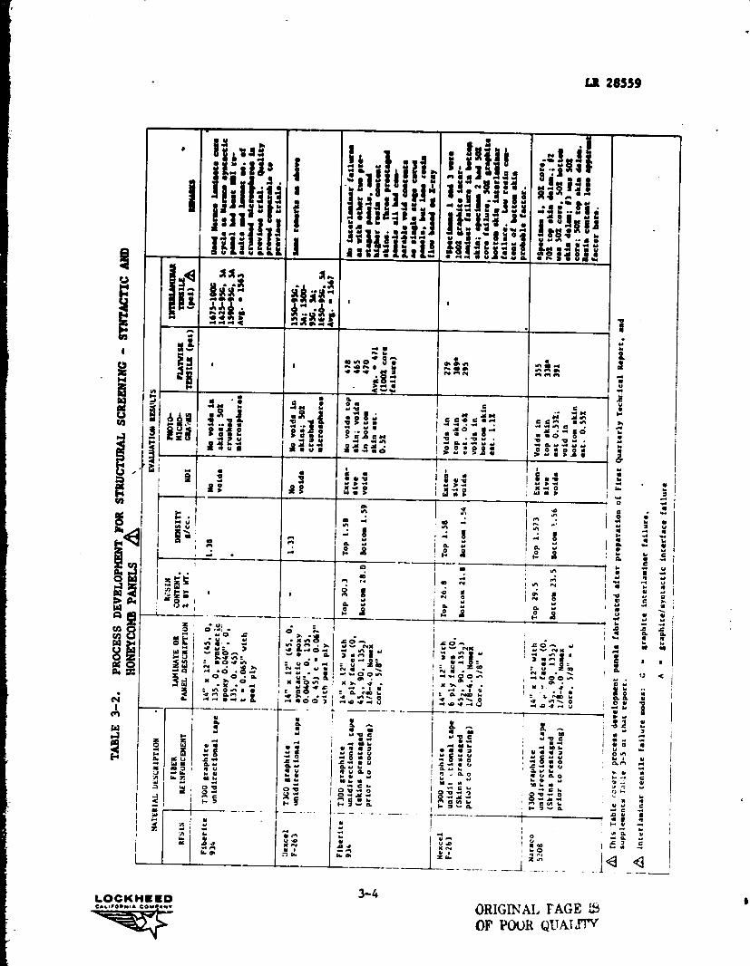
These activities were summarized in Table 3-5 of the First Quarterly Report
(Reference 1) and an updated summary of further process development activities
since that report is given in Table 3-2. Significant items in the process
development activity include:
e Fabrication of solid laminate graphite, Kevlar 49 and hybrid speci-mens - Acceptable laminates were fabricated using modified vendorcure cycles. The bleeder arrangement was designe3 to achieve mini-mum flow with the 35 percent resin content prepreg system.
e Fabrication of graphite/syntactic panels - The syntactic test panelswere fabricated using the same cure cycles used for solid laminatespecimens with each of the three resins.
e Fabrication of honeycomb panels - Panels were fabricated with graph-ite faces cocured to the Nomex cure, using two procedures: a single-stage cocuring cycle, and prebleeding of the skins prior to cocuring.Excessive resin flow occurred with the single-stage procedure andextensive skin porosity was fouLi in all panels by photopiccographs.The preblec skins had less porosity and resin flow, but in severalinstances graphite interlamirar failures occurred in flatwire tensiletests. In view of these problems and the limited available time forfurther process development, a decision was made to fabricate allhoneycomb test panels with pre-cured, &econdarily bonded skins.
A summary of test panels used in the structural screening tests is
given in Table 3-3, along with results of tests used to verify quality of
the panels.
The structural screening tests have been completed, and test results
are given in Table 3-4 for the solid laminate specimens, is Table 3-5 for
the graphite/syntactic specimens, and in Table 3-6 for the honeycomb test
panels. The dynamic flexure test results on the graphite tape laminate
specimens are shown in Figure 3-1.
Table 3-7 gives the ranking of test results for the three candidate sys-
tems. Narmco 5208 and Fiberite 934 have generally superior mechanical pro-
perties to Hexcel F-263. The 180 0F wet flexure, short-beam shear, and com-
pression values in the graphite tape laminates show the Hexcel F-263 system to
be more affected by this environment than the other systems. The 180 0 E wet
data on the graphite fabric laminates also show the Hexcel system with lower
3-3LOCKHEEDCALIFORNIA COMPANY
Ile
031 3 i6.4jKl t i
• I •Ch ewN P1ry nNN
iJ. a a n•al a a r n N~Jt N.•1r o o r ^^ n n O rnaioI 91 6 Y .. Y •/ H 6 N w
p Y Y
I i u Y 7 S• ; u 4> S•
r, 1r YO I u > w
t ^ w ^r—
w r >
JN
;^ aI 6 YH •
1 O
O N
N OY
6
^ w S
Ij
ONnNH y6 vF SO
I NMI N ry
j ry
u6 pO m
bA 28559
^ s
aY ^e
w . i ^ a ., ^ Ms3^^ s $^s^^y ^ Y . ^ Y ^ V M ^ ^ ^ N y ^ ^ ^ y RN'
1ia4 ^
^^ M N^~^ ^ ^M w ^'J O^ ^ SA O M Y
p wy1 ^ • •+i
,^ ^• ^ 1! y ^pyyp1 ^
S
y ^ ij ^• .. ^ •IIw V
1r^ll^n I^w
x xM'Al w
i ^r ,Q^
w1
^l^gy
w • 1
w . ••.:r S ^i 11^ w .+ f
^ M
a
t
. Y^ Y ^/ « Y Y V
.a+1xn
i• Y n I i• M n l i• M • O
U^
D ^^R•
fi w•'7w I N
J
aka
H
o IY^1 ^
»al I I
!.W! ac t i N •.. yO
wl• .." ^
.. p I• O J Np
1N•1-1 0.0 . O ,.^1J K >.Op 61!1 K • .ytfi. N O •n ^ .
Z r'1 61'1d -yN .•.1Y 6_^
YA
^+ YZ N
IYN ^ dy°^I •u
NI . o v
T
I ^rn I V.
^ I asW p
NA
W
I.O1.1H.0..1J
J
VFT
1
I ° >.
opxN
^
v{ L. r O• qt O. I v N K V
^
uG.-.I r x
y
i u v N x I I^ ^ r ..^ ^ V n.Ni 1 ^ ^^^
o
^V O wN wl Y •' ^\ ^^ U ZOO•q Y • ^ ^ I N•^W PON N 11•. \I N SON
V S OI •-1V OON
IY
1 M Y.O/ J i K.>i .j Y K .Ti .J y I x 7. P JO Y 6 r0 yI
16 ry0 y I 1 4i^•y •OO 1 I .r •p J,..1 Y j w.o J.r UJ OH .O J .•1 U
6 y ^ I ^ 4
Y V 1IlI Y 7 C y—a O^^ ^•p O OI •.• Y yI .y m y"^ O r O• O I Q• O C r VO Y 46 . Y I V t - • UY Y I Y Y 6 l0+
S u•1 G 0
Ia u 6 OO^ Y y n I y ._ N y
m1• 4 v1d y0 7 j 0 7 ..1 O
n CI ^ y c y
H H y v 6 F 7 v 6 F 7^
.^i4 I
oV x NY 1..w
a^wel
V OK Nil:.
I^ Oz,n
••1
ON
1 n6 orIOr
1•
Y 7x > N
aN
•. aY6 QY
N S
j M
W y
i
—1 0 ..•
^ y
11•
Y ' •
I 6 W ~•j y y y
I^i
I Y '^ r 1•
F .^
1 • 6 d
• •t y
•
6V t
C uC6 o s
' C6 Y 44
Y 7 Y'O y y
I i4 p yI u
O N
y 1 Y
Gh 1'^ M
M yron I- y
. 4. e e I• n 7H .
4r Y j
o.I w a
pa
ppp^Z > Z >
LOCKNESD 3-4CAMIORMIA COMRAN •
OR,IGINAI. PAGE 2S
OF POOR QUXITT''

1
LR 28559
1.
^y
I
J 1 I 1 1
Mi MM M
yN 4yS
^ 1 1 1 1
ysN ^ O J ^
li >w M M O 1N UUUUM
aaH
zN
M9
OOO•n•1 ^ ^^N PPP1 1 1 1 1 1 1 1 v 1 1 1
8 8 N ; O 1^1 O^ ; ^O ^I ^ MN •• t N N rv^ N t
1 1 1 1 1 1 1 I I I I 1 1
N I N I pI I „ 1.M•1 I O
1 1 I I I
xw M r -w Y M Y> t^ 7 61 9 0 O
^ r> r 0
^ u N 4 N qpi 9•. w w N N ti w O 7 6yp'•. T •o.^ `
Op>
I .Yi9pN^ f p
►pY p
>p>
pY >p p> o>b r u w Y 20
p>
00! y
yu 0
4IDp > w s
^-^^e
>LO
I^^
>6
N
i
H
7L
.^j
iO
g ^
i4
M
SM
i
O
,LO
Z v~i O N n Z Y u n
9 O^; 2t
i0
2 w n
doti
^e >g e >g e >g ^ ze ^^_ ^e $>
O>N` ^ ^ N N N I.P1 N N N 1
IN h1. } N
IY1r1ZrN J ^ r. P .> O n M
` 1 1nwl i^.i M
MN ♦a ^ .0N M .+i mI N ^ 11
.3/ 6 0 N r T• _• O T .y r • O T >. •II ^! O u 1 6 O N J ww
^ 6^ F au ' 6.. ON IL 6.. 6v^1 i^ NUU u •n .r
O M b Y ^ O M epi M IG M q y , .n Y v y N \ .^ IV1 M K .-. M K^ I U M N K M^ ^ K it K n' eV•r ^n T I ^n >. ^n f ..
{i{ ,,11 OM O .i Nn OM : O NN OM : OI: ^nN MO u n OHO n OP
• Hrr .^. H . .q .Ni .. n T ti N ~ .Ni . rrvi . .rv. rn ti M ~ .N-1
.-. w M T' O I ^ ^ .N O G Q O O C' .r O G I O C^ O' O^ O
M O KJO Ma K K ti N •i0 KJ K K UO KJO KJI K .'. K `O^ x .^-+ K .ti O, x ..+0^• N/ rYr : . N N1 . N: 1 1YY^ N O 1 N 1
oo
J.O J •ar 0 .a•1 V .ali u G .a.^a .a•1 0 MJ J J u1 •Ji^^ .J-I ^^.Jr J' .J.r i u 6 nMOO ^.MiO u n.r0 u
f, l y Y Y 7. V .-Yi > T I V> .4iu u
EI y w T Yy r v T `° Iy M T i`Oa
w>.W w p N 6N H d y 6N i Q V I •r. G 6 w 6K 7 wYi w u Y ^ wY. ^ ^^ ^ Y I • ^ u O J y ^ Y J Y
yYYYiiip•••1
Y u , u> u u 4 u T u .Yi .Yi u I Y •. .Y.W D pwl P O u 1 0^ P 6 u 6 6m P Yu pu Du L {^, I
r8• N : pQY : •4p pgi0 ^ ^
8.0 :
810
8Y N M
8a/
810 w .0 ` I Y w '
• I'1a i ^P • ^N > ^P r4 Iw .Kj ••> n' I8\ 8 n
M u F n Y M a M u F 1 h J H u {+ ry >L 1•• 4 H u H u-
u
1
J. u
i 4+ O L^ M t^V C^ Y Y •OZ N i w. P i W `^_-L 4. P S 4.
_y
Y
W •' w 0 ' ^ YT,
3-5LOCKHEEDCwu10•N I • corns.—
—q,: 71r^
. n

a0U
N
a
H
H
U
C
.sY
w
u r
S.
• Y
N
Q ^is
Y Y
Y Y
n
0
Y
10
P'1
N1
•V1'1 1 1 1 1 1 1 1 1 1
W MM1y L7 M a N ^ P O N P M1+ JJ x ., x ^ ^. ^.
^` 1 1 1 1 1 1 1 1
1 1 1 r 1 r 1 1 1
O YY 1 1 1 1 1 1 1 1 1
YYY N1 1 1 1 1 1 1 1 1
1--
? N. t g a 3 ? ANN. i i" 1 ^Y o y l ^^e .°1 .ri w w
► •O • p O\ MNO\ ► •. • ► O\ NON .. •J\ P ON NON//p N Y y N w N M Y Y N yN N . rin1 V .1. O Y • Y O. • •Y 1. N. • 1 O 9. ♦ O ♦ .•• 1• I I 'I N 1 • O J • r J
)<^ i h Y 1.7 L rl i M Y S N YHY e Y Y I N Y i0 oe.e oN.g^ R°:-.` lol`+,.0'1^ is o..^ ol.^ e
Y^1 R., r N-.^ u nN\ N n p ur NN\ u.. n.. y u n+^
W tl..^•1 s tl Y .+~ M M tl •NZ./ M^~ Y Y tl ♦.. tl M tl ^N M! y I tl w ..M ^[
YpK JIO h s 00 C ^ yN OL ^J{h L ^O ^..tO G
R rP IN hyJ^ 1 /O s r +I IM R +^' N R u • J7 r O •l.
IN
h ^ oY n
L7
u
y A ` y Y
M Y a
• 4 '^ a as w • ^'r M •° w•Yi I ••iw g r H^g Y .1 S Y Y ^1 Y y a Y D
yat r T •1 ` '1 Y ..•. C6 6 P O V C Q P OP Y C •' • u1•. JI J Y~ V JI J ••I Lw J v YP • : • Y Y • • Y • • + +
g x s!pQ^
iQ{ s` s ^ )` s ^ x ^ s w s•
N u ^ ^ 1^. a M ^ Y'^ F• Y lyi 1+ .•. Yl w 1. P+^
s° r ••^s i ss
x ^^7^ M 111 .' ^ ^ W —_CJ
yWy Z Y i
i O N
EYp Y
O G4
Le u
Y
Y^ w
`o
2
<3,^
LR 28559
LOCKHEEDC&l1IO.N 1A COM2AWY
ORIGINAL PAGE IS
3-6
OF POOR ^:JALITY
f

1
I
4'
LR 28559
wO O. n ao n ql e+1 0. n h .r OIZ N U ^O v1 N M1 u1 U1 P1 P1 1+1 G ^ .t
Q
••t1q N h a0 O O O N .D -1(Ni. O n .p P1 n ,-1 n p .Q ,,,^ I I 1> ^O .O .D ^O .O .D .D h .O
z o v,
yrl
UQy
PWG K cO .D W N .D J Y1 N 1.1 r•IN N N N
cN4r, N M .T a+1 a+1
Ik,,llN f/y
yN p {y N r'- O, O^ fn •S T N ^OFIYi [p••G vl
P. H tN e,N 1 1 1 .O.•r ellr-1 a nN ,.rr•i ,-I.••I[r NN
N
C 1 1 I 1 1 I I I 1 1 I Icn
vie
cna^ Wr vi W a) o
{pyG NLnF Y.
elO O r 1 1 1 1 1 1 1 I I
U NIn
q N3. W .••1 O co O. O O. O.O OG N I I I I I I n O. ^t •-I
xN
I E•^ F.an
nIn
O^N
.rn
mO4N r-
e•, MNan
3O W N N f^1 r-1 J O IT n O N N O f^an W H HF P. OP1 O.••I O%IT W.-I .-Id .DW NV1 ofn s
n On n OFI•I
.r N n p. S co W IO N N N N N Ma anO N In 40 J lo O .O M N n N 7p I+1x Q W I a N N n .r n co J lO •-I m V1 NN F
aGoG vl
a•dn O
...+n O^
Wr1O
Oo
co11nen
•4/n
.OM
yen
n
NO.••^ I"a O O^ O. ^ W .O N N C1
O^ ^ ^ N M N^ ^
NN O^.. N
.1 P n dp N •-/ .-I J N P1
WWN W h1 V1 .••1 a 1 W I'1 W O W In I'1 p.W' N) 07 N lD lO T N O .N O ? ^O .1W N .-1 .^ O n n I t+1 I+1 en vt In vt
a
W O
w 5 c rn n o rn .i v W v, coQ • 1 01 W aY n W N 1/1 P•1
.•. N .•I W n W N .•1 .•^ 31 I•'1 mFa
NyH
1'1 N ^} f+l W N P1 O •O tT .^ Jy .D n aT O. o O N N In ^p I'1
F ^G n co In a,mrn O s I.1 I+1 Lnto e-I .--1 .-1 r••1
z W s f'1 W -.D n W J I••^ W s nZ y In I^ •O O •O o M o In lO°. IInn °. 1N m °. wF a InNAzV u
+aH
O N •} y ?y w
^yCIHi aWG a n N W J >W F cn
Iw M d p
H E • 4 .r fT In x C7oC O u o u o i In
a v"v spp, .^ r .n t v, ro o ro `^,L
Wd J Iv V
b..>
1..
H6d^. O •. O d 1
cnH
cn
HU)wH
H
QN
O
1
zHzWWaU
CHaW
^aH!
.II.
1
Wa
w
0
dO3'Od•-i
•rl
y
b
M 4Y My '7u c ^
O Md •.I yd u ).,
u C tlu +1
w uO
7 W >^w y O ^OId Y •^IY y Y n> W a> YN
r MC d
W O ud F. U waC Y 7 Cy
A yy 4 y Yd d Y yCc E a uN d u> u w
-+ E o 0O 11 O•
6 ^O •o
u uu
C7 I H .O Wz a 1 .
3-7LOCKHEED / ICAII/OMN- COMOANv

3-8 , gjjt;tN aL PAGE: LS
,1F Yu0R' (aUA'XTY.LOCKHEED
6
LR 28559
TABLE 3-5. MATERIAL SCREENING OF GRAPHITE/SYNTACTIC - SUMWyOF TEST RESULTS
TYPE OF TEST 5208 934 F263Compression RTD KSI 73.8
THICK IN .071.072.072
55.5.084
Compression RTD KS'I 58.7 56.0after impact41.3
54.6
Flexure®45.0 39.4
RTD STR KSI 122.5 143.9 114.9MOD HSI 7.4 8.2 7.1THICK IN . 077 .070 .082180W STR KSI 119.7 120.8
MOD HSI 10.8 10.6104.310,3THICK IN .073 .063 .082
Short-BeamShear
RTD PSI "'789& 317®
65D PSI 3542 2690®
1614
1520THICK180W
INPSI 2143& 2259A 1309THICKIN •069 .073 .083
Interlam. Tension RTD PSI® 2212 2190 1580Density
g/cc 1.20 1.31 1.08
NOTE: • Average of three tests
• Nominal Thickness - . 020 each face + . 040 core - . 080 total• © Span- to-thickness ratio - 32
• ® Coef. of variation >.10%
I
• ® Coef. of variation >20%
• L4^j Most failure modes graphite to syntactic.
I• ® Least Damage
• ® Nost Damage
• LaYuP: (45/0/135/0/bYN)s
• RTD ' Room temperature tests unconditioned• 18OW - 180 OF tests after 7 days immersior. in distilled water
at 150OF
A

LR 28559
TABLE 3-6. MATERIAL SCREENING OF HONEYCOMB SANDWICH TEST SPECIMENS
SANDWICH BEAM COMPRESSION
COMPRESSIVE STRENGTH (ksi)PANEL
CONTROL AFTER IMPACT **CONSTRUCTION RESIN
Graphite Tape Skins (0, Narmco 39.3 38.2
4521 90, 1352); 1/8 - 4.0PCF Nomex core, 5/8 in.
5208
thick. Fiberite 50.6 37.4934
Hexcel 46.6 33.3F-263
Kevlar-49 Fabric Skins (45, Narmco 20.5 18.1
0, 135, 45); 1/8 - 4.0 PCF 5208Nomex core, 5/8 in. thick.
Fiberite 19.2 16.8934
Hexcel 19.9 16.9F-263
Graphite Tape/Kevlar-49 Narmco 26.4 26.8
Hybrid Skins (Ok , 452G , 52081352G , Ok); 1/8 - 4.0 PCFNomex core,-5/8 in. Fiberite 25.8 25.8
thick. 934
Hexcel 26.4 24.3F-263
V**Impacted at 2. ft lb with 1.0 in. di; sphere
l
3-9LOCKHEED

HaaU)waHwHVpp^ _
04 oclUw ^w .4>
10H a1
HH^+ M
or
OwOUz alM rl
z, uNv
n1
WaasdH
LR 28559
^(^ I M M M e'! 1 N M M I M I I MW^^ I r r t^ N 1 r N r I N I I r
NNO '"
IA
I N N N — 1 N r N I r I I r
> ^ r
QYW
1 M M N N I r M r I N ( I NW
( 1 1 I I N}_ r N r M M N N M
= dQI N r M r I N ^- M I r I I r
I N N N N I N N N I N I I Nj¢^ W
jm I I I I I NM M r M M M MW U.
l
^YNa I W- V- N 'r- I r R M I r I I W.-
NI r r M M 1 N M I I I I N
t- U
x cc
QQ I N M N N I r I r I I I IIX
^W
1clI M N r r I M 1 N I I I I N
WM M M M M M M I M M M M M M
~ WW
O^ nQI-` M N r N N N N r 1 r N r N N rQ
M^ r N r r r r N I N r N r r r
cc C G O Q Wy r^^ H^ H oc I .. oc ac o 3 ac
cc
OO
coz
zQ
U.d
p C IL) Q
WH
i zN
QW
Wcc
^ a
^. Q WV3HS -j z o a W3unx3iAg
WV38 -1dOHS Z > W zo x Q >
Q31VNIWV1 31VNIWVI
3-10LOCKHEEDc-FO RN., COMPA-

LR 28559
Aole
N^
/, M
L
v p^
kF^ !M 1 LLJ H
N W w
^^
CL u
M
~
JW
AGW r..^
^NNCPI O IO
MIww-
/^D} Z
C .O
^60w
N
O 00 NN N N N 1: .-i
isd 901 smnaOW 3anx-n3 OIWVNAa
8w
/
1
=' aoM N
LOCKHEED 3-11cu ^rowr.^• COYI^Nr

LR 28559
values. Narmco 5208 and Fiberite 934 are more closely comparable, but on
balance Narmco system holds an edge in hot, wet properties and in general
mechanical properties. The Kevlar 49 data provides less distinction between
the three systems, but th.Q elimination of Kevlar 49 from the design concepts
made this data of less significance in the resin selection.
The dynamic flexure curves provide the clearest ranking of the three
resins, with Narmco 5208 significantly superior in the dry condition and
after moisture exposure. The relative superiority of Narmco 5208 in this
property increases with increased temperature and moisture exposure.
The graphite/syntactic test data also showed Narmco 5208 and Fiberite
934 having superior mechanical properties over Hexcel F-263, particularly
in short-beam shear. Fiberite 934 showed some higher values than Narmco
5208 in flexure and short-beam shear. In summary, the syntactic panels
must be considered as not clearly differentiating between the three candi-
date resins, but the data does demonstrate compatibility of the syntactic
system with the three candidate resins.
The honeycomb sandwich test panels were impacted at a two foot pound
energy level using a steel rod and residual sandwich beam compression
properties were determined. The results showed a greater proportional drop
occurred with the graphite faced panels than with the Kevlar 49 or hybrid
faced panels. Beam compression values after impact on the graphite panels
were comparable for the three resins, and the results did not indicate any
significant differences in impact resistance of the three candidate resins.
3.2 PRODUCIBILITY SCREENING TESTS
The producibility aspects of the three candidate resin systems were
evaluated by Avco. Flat plates, sections of the rib configuration, and
sandwich plates were fabricated. During fabrication the tack, backing peper
adhesion, bleed characteristics, drilling and sawing characteristics, and
drapability were evaluated. The results of this evaluation, shown in
Table 3-8, do not indicate a clear-cut producibility superiority of one sys-
tem over the other two.
'LOCKHEED3-12
C.LI.p.wI• COMPA.'

3-13LOCKHEEDCAUrO ft- A [OMIANV
adsaQ I ww ^ w v^v www
rwag 0 00 0 1 11 1
a.
ITT=Q w w w w I I I I I I
rYw
Y >
u poolt w A. m w I I I Ic^ •u
i'HQY aadvd BuTx0a8 o w o 0 U 1 1 1 0.0 Al
432.1 c3wv 0 1 www www
Y urJ ^
y M
c cM '^.o 10
aY 0 .0^ uT W
uw u
F Y d ds.p V) N
.-1
Y Oh .0 O 0%
x a G'ic x
a M+c
.^.1J N N Jv (^ v
.-1-1
u0 u0 uuvO. N J M J +^ PJ .^
w01 V))
-4
eO^f cA.O N V .O
m m0 >c 0 0
c o .+ o o ^+o a J.ru o-
_
Jo o- -u0
v+P7
u1. en
Inn
oIn
os LmN .i .-1 -1m0 0
a-.0 0 0- 19m0U Ol T O. O V)WO
T.6 T T T X TY
V7 W V1 a. V1 13.V\ n:0-4
Y u u.^M Y Y Ij L
,r1+
W 0.uU O N
[r.0
Fup F XWO. 0VI
mV V y
V N U 5.9 Z
C'i Y"^ arY ^` OD J ^"^ m GG J Go J ^"^oc o e, .o 0
g0 o rN .o o e+ .o
N 01 NV1
NV1
NN
NGI^NV1
NO%NN
Q rl NP1 J -'1 NMJ -.-INt+1z Q. C6 0. GL KWw NN(A
z
1-I
Hd
HaHHU
Caa
dF`IawH
GD101
w1M
H
d4H
Y b 7u Y OY M Yrl M 0'.
a 0 r M a80Y0lu0O +1 O Y O
L) c)waocz
G I 1 1 1 1 12wV V V 1+- v. !C IW.a
LR 28559

:.R 28559
Coupons fcr physical and mechanical property tests were machined from
each of the parts described in Table 3-8. Data from fiber-volume measure-
ments, short-beam shear, flexure, and flatwise tensile tests is presented
in Table 3-9. In general, this data indicated that the 5208 system had
the highest mechanical properties.
In evaluation of qualitative data, no one material was significantly
better than the others. However, the following observations were;
• Fabric layup is easier than tape layup.
• All specimens were preplied prior to layup and drapability isbetter with fabric than tape.
• 48-inch fabric uses less labor to cut the composite than 12-inch tape.
• During layup, errors are more easily correctable with fabric thantape.
• Fabric materials with same resin content exhibit handling propertiesof tape materials of less resin content; this is a result of themethod of resin impregnation. This condition is more pronouncedwith older materials.
• The surface finish on tape is better than with fabric.
• Syntactic sandwich panels are much easier to layup than honeycombsandwich panels.
• The Kevlar panels are more difficult to cut and machine than graphite.
• The 285 Kevlar weave has good drapability on double-curved surfaces.The corners on the sandwich panels can be formed without slittingand lapping the corners.
LOCKHEED3-14
c•u.owMU COY D.I^•

T1N
ww
LR 28559
H
WN
P4
HWHz
UWA4f/1
1
OH
a
H.7Hf>:1F-1UaAOAGP.
o+1M
w
OW -A %TW N
to in %D MW U W
k > uW
w n n o
o ^ oaa,
.w couM
$4 u
N 01 L O O in --T yO 0 .r .ter O O m IrU
1^+ W ^-OI
W
0 °X W
oo H Ln 0% c,4
N da n^C s "o .'-4
Vi ! M m f+'
O O O.^ O W • O O .O
V1 u 1 f^W W "4 O 0% 0% OD %D N .T -T Tf W Ai .-A
^O
W 41 • .A
W O .-I m f:O 10 N N N (I; ^'. L) v l .^ W pU-rf
HW > 10+ N
mt•+ V4 d .-11W ,^ E a T+
s n 0 0 s aD O m—4 0 .. ^ W wW 00A n
C^44 00 C+ N e+1 ^O O O+ ; O to L .-1 O.c .D ^D ^n n .o n %D w d w M M M c0 M
W ,atO m (A
p41 Gila
t^ Ofl rl cd•-1 W
o\ W Wn W .-r
xX
UCG W O
,Oi uDC
W ^+ W x .a u I I W W•• •• ++ u u o% eW W W ow r! rl 17 C% O+ 7 rl ^^
a W W a m .D $4 w 1-4 oce a a m .. cd co a .0 u W W)H
H H H O HW 1 4w pk 1 1 0 T
co Go 0 CD coO IT M O >+ O O IT M 0 .T M X01^. V4N M N N M %D N M %D W co 41v1 O% N to v V1 N O% N L!1 O% N .0
W fr O XN rl Ot0 to m $4V V4 O flH O .4 N M .T -+ N M .T -4 N M
c
zva A4 f1. Pr p4 04 t>4 a N 0 v) H EW. d
ue
N
LOCKHEED 3-15
0
-"q^

LR 28559
In summary, the evaluation to date of the materials tested indicates
that the fabric material with the Narmco 5208 resin is superior from a manu-
facturing producibility standpoint for the L-1011 advanced composite aileron.
As part of the producibility screening tests, Avco has made a prelim-
inary evaluation of tooling techniques for the channel section ribs to be
used for the aileron assembly. Graphite fabric ribs were made using both
male and female tooling. Conventional bagging approaches and formed rubber
bags (see Figures 3-2 and 3-3) were used on both tools. In addition, several
ribs were made in a female tool using a formed rubber block in conjunction
with a conventional vacuum bag.
Parts made in a female tool using a conventional vacuum bag or a formed
rubber bag showed evidence of bridging and porosity in the radii of the rib.
Parts made in the male tool showed no evidence of bridging in the radii;
however, the parts did have a large dimensional variance. The dimensional
problems using a male tool appear to be correctable to a large extent by
tool development; however, the accumulation of tolerances to the outside
mold liues for the ribs and spar could be a problem. Ribs fabricated using
the female tool in conjunction with a rubber block and conventional bagging
showed no evidence of bridging or porosity in the radii.
A preliminary evaluation of the tooling techniques investigated indi-
cates that the female tool using a rubber block and conventional bag is the
best method for fabricating the ribs and spar of the aileron. Additional
process development activities will be conducted during Task II to firmly
establish th q fabrication approach.
3.3 SELECTED MATERIALS
In addition to the data from the structural scu ppning tests, other
factors entered into the selection of the resin system. These included
the results of the Producibility Screening tests performed at Avco. Addi-
tional factors were available data base and processing history at Lockheed;
and availability of the system i-. preplied tape form, which proved to be
an essential factor in reducing production costs.
3-16LOCKHEEDC^II.OAMi• GOY.^ p v 0

LR 28559
Figure 3-2. Male Tool Rubber Bag
Figure 3-3. Female Tool Rubber Bag
ORIGINAL PAGE IS
3-17
OF POOR QUAI.TI'YJLOCKHEED I

LR 28559
Consideration of all this information led to the decision to use
Narmco's 5208 prepreg system in the ACA program, with the selected rein-
forcement forms of 1.5 mil unidirectional tape and bidirectional 13 mil,
satin weave graphite fabric. The basic reasons for this selection are
summarized as follows:
• Superior hot, wet properties of 5208
• Equivalent processability of 5208 to the other candidate systems
• Availability of 5208 allowables data from the Advanced CompositeVertical Fin (ACVF) Program NASA Contract NAS1-14000.
• Development of processing experience at Lockheaa with 5208 fromthe ACVF program
• Narmco's position as the only one of the candidate suppliers tomake a firm commitment for development of preplying capability.
3-]8LOCKHEEDCAL I FOR M1. COMPAMW

LR 28559
SECTION 4
TASK II - DESIGN AND ANALYSIS, COMPONENT DEFINITION
Component definition, which is the design and analysis of the selected
ACA concept, has been initiated during the reporting period. Activities
within component definition are reported under the headings detail design,
structural analysis, and material and producibility analysis.
4.1 DETAIL DESIGN
The basic design and interface requirements drawing has been completed.
This drawing (Figure 4-1) defines existing parts which will be used
unchanged, interchangeability requirements, electrical bonding and
grounding, drainage, smoothness and gaps, and identifies new detail parts,
assemblies, and installations; it is for design control only, and authorizes
no fabrication or tooling.
Detail design activity for the covers has been initiated. Alternate
approaches to the intersection of the rib doublers and spar doublers are
curre being investigated. Results of these studies will be included in
the next technical report.
4.2 STRUCTURAL ANALYSIS
The activities reported within this task include: development of the
NASTRAN finite element model, development of the material test plans fcr
design allowables, and the weight history and current status of the ACA.
4.2.1 NASTRAN Model
Based on the selected design concept a NASTRAN three-dimensional Finite
Element Model (FEM) of the aileron is being developed. The purpose of the FEM
LOCKHEED 4-1
CALIFORN I A COM;ANV

LR 28559
Is to determine internal loads, deflections, and structural influence
coefficients (SIC's). The model includes a representation of the actuators.
The Lockheed- developed anisotropic quadrilateral membrane element, a linear
stress function element, is used to model the surfaces and webs.
The general layout of the model is shown in Figure 4-2. The models
for the actuator and hinges are shown in Figure 4-3. Auxiliary stations
at models 1100, 1300, 1700, 2000, 2300 do include rib panels, or rib
caps. They have been included in the model to provide additional detail
for the stress pattern in the surfaces.
4.2.2 Development of Material Verification Test Plans
The material evaluation (Task I) IeJ to the selection of preplied
T300/5208 graphite/epoxy tape for the covers :nd spars and T300/5208
24 x 23 x 8HS graphite fabric/epoxy for the ribs. A hybrid of fabric and
tape was selected for the main rib caps.
The tape selected for the aileron is 7.5 mils/ply. The unidirectional
tape properties, developed as part of Lockheed's Advanced Composite Vertical
Fin ACVF Program NASA Contract NAS1-1400, will be used to compute laminate
properties.
The ply level propert i es for T300/5208 24 x 23 x 8HS graphite fabric/
epoxy will be developed by tests of 00 and +450 fabric laminates. For ply
level allowables 30 replicates will be tested at room temperature, dry
to establish a sufficient statistical base to compute 'B' basis allowables;
10 replicates each tested at -65 0F and 1800F(wet) will establish environmental
adjustment factors; and 5 replicates each at fiber volume extremes (outside
of specification limits) will determine the effect of high or low fiber
volumes on properties. The question of whether the dry or wet state is
most critical for a given test mode (tension, compression, or shear) at
-650F will be determined by testing 5 replicates each for both conditions
and testing 5 more replicates for the critical state. The results of these
tests will be used to develop ply-level allowables for fabric so that
LOCKHEED 4-2uu.o.N-• Co....,..
I

r /
^^1ILeNI /LI/
i^--/L/73!1•!0, .^') /Na7L
L7031 . /e/ Ru /NanL1L. 1 7594-0el R/. /N5
1i/7L
/e /7!!f •/01 Rio IN37L
LV^ "
— I
a@t111
.
^7,
ua
I4=17
ORIGINAL PAGE IFOF POOR QUALM
^2d/7 Rl r
^YpILR CONTOUR
LWIR CoN soup
L,N/AG olf /apNL
FOLDOUT FRAME
1
w\: L +t-.M.'.^pH,7{°u' 9 e^^ 'S' ^.t.+yc!as4^.^++ik
I !►IH Ial.1 ^i7.Op .^01T9e^ ll.^
I ^ •u! I •A-! ^ u! ` . Ir S^
^v Y--'r•r.l^---^}^-!^ it sl 7'^^ tom---^
I ^
IULC"k 1404r
BraNI,LI;ti
)/u /rfoeeo-aI rLl p/vb Rss7 —
/617217-IO 1 nI Insrc/ I
^^ I
tA22MIl IlN^ , ^ , ! ^
SECTION A-A rowl ;/) I
LOCKHEEDCALIF*NWA COMPANv

Arrllw.r - •3/CI ^N/731^ f
II
au.
/L^7a/I-iOi lil ^NSII ^.Af
—lN rala ♦a. w.I.sra flfait
MisA
^T • aaoier wiI ,wsrc
L-rsa^s .o o. ri wtoGl t srL !Q
LR 28559
r
Hf11Sf-.r So~ •sri s—
NJ 73/4 •.01 pare «Am t a R
rw ^ .As ^ I
\ 1 .^f^ ^ff .a s ' ' alit',i iL`•f •.sir
----- -- — —.a.L. : F__—
' ^ `i^l7fli -dr IJI 'qfl
1 Ia3 l•
pRIGMAL PAGE lbOF POOR QUALITY
q rf.ai w Ia 3 r . 3 . r0. ^w ^E+ lf NaN-• +.^I ••1 •t+•.r •a• w(O OrL[IIi- .Lf .C..J •G rw.. uc f3w17 ..( S..
^i ifl -0.3 f I ^• ,i b •rS/I 0..4 .f..ftf 4• w .1 J I.,.. "r II]• f•J.3
_Nf• G . I3 r.' +(1 •I III • . •(IC.I.:I /1. • r Ili
43ltt 0.6 ifl t.H NI w .G S w01•..Ifl /G..1 ./w♦ So' OK .lfif! ^^. 1. (C*.: N.O .G
• h^... • .^.^ N. ... .,.. 174
SM V .O (sswra iw MV, I.C. .i N +.Jl ry. pfrw ~f :lj{ Open . ISO Ca.w V ra an
me .IC.s.i w o'•a =04" {r•O.fi SCSI)—" cm"
No 9.00" Its YS.- .twjL Sita..f.O.3 .ss M..+. WWI
411110.a smil
411IRTS
Figure 4-1. Basic Design Drawing(Sheet 1 of 2)
JA
4-3FOIDOU'^ FRA.:.. F ^—
I1

ORIGINAL PAGE ISOF POOR QUALITY
FOLDOUT FRAME I
PRECEDING PAGE BLANK NOT FIL?.IED
r
^ K ^UwtO (j. ►030
LIT
(W\ IIf- 11A 143 ,/3
rL
•i^ ,I S'. LpiitJ LO. ra3w •3 ua^}v/YJf^ /,LIOr N ^' M! 1 14 it s!i' i11) `
\K^/I 7101
t1 \/ /^ LIMO, ^Yetoru/•+n ^ ^ ` ^ •^fJS /IJ ' ^ (fwt •r',^ IIf
LfJ30JN /!l0/Kt /, rriM6 C, ,Jlllfl MhY(rt Jr r3wr110 r, rr, .G '^ ^NMrrI^PIMKr/. rnIfssi•3. r1w Joe I,rr,-*Q
m33"3 3w*/. Posi r,cw iwD,Cw70A.0(/VIEW B-B IO+t fG,l
LOCKHEEDCwU10Ati•w COYow
"*I& Mott-s/1
l 2.6 Orw Mote

LR 28559
1st75rs s•t sr/ruC,lr5s7/^1^ f
I
1sts/:s s!/.o "IST& //f
1550"7~ AtYA/1.IS nrsr2 /t!
1648 Os-mi CA rift /ssr
rr1"11/M1-.H drl• I!!.
/,. +K!
+ wau.er
YI
I
^1 14.1 /A ♦
Litr9 r/6.,rfie`/,rr,.( Ltllr.K.."rms
rORIGINAL PAGE ISOF POOR (QUALITY
FOLDOUT FRAME
SECT/ON Ci -C mwt IC's
Figure 4-1. Basic Design Drawing
(Sheet 2 of 2)
4-5

PRECEDING PAGE BLANK NOT FILAIED
LR 28559
sa
IR213 2W -
139.p9 2700
12LIN 2200
117.4 2100
111.1 2000
107AN 1900
102M8 1800
99.8 1700
921187 1600
78.09 1500
64.09 1400
61.1 1300
57.087 1200
54.854 1100
52.%03 900
_^•, 11 TT
IT CO)RD.
1 1411
SECTION
000 36.627
'500 132.68
!300 128.826
''.200 126.1N
!100 117.4
Ow 111.1
900 107.p9B17
800-^ 17
MAN700 98.8
600 92.087
1V CO )RD.
500 78.09
400 64.09
300 61.1200
17
57.087
100 50.594
-7QJ5 28_83
Figure 4-2. Composite Aileron Finite Element Model
4-7LOCKHEEDC0.4-1

LR 28559
STATION:
O3 1 1 I II 1
1 I I i iI I I
O6a 10 CA 14 16aQ
TYPICAL SECTION
AT HINGE + ACTUATOR RIBS AT MODEL STATIONS 1200 AND 1800
SPC7
1^ 12001800
SPOINT1891
17/ UPPER
1200.00"EXTREMEACTUATORS, STATIL 00 /NS 18 18
1900.00e r
.000" 19
/
1 OMPC
LOWER1211216 21 EXTREMES1816
1816SPOINT
ALTERNATIVELY1891
ACTUATOR END POINTS XX17,16,19, 20, 21 CELAS 3LOCATED TO REFLECT ACTUATOR DIRECTION SPC 1FOR DIFFERENT AILERON POSITIONS.
Figure 4-3. Actuator and Hinge Support Stations
4-8LOCKHEEDCALIFORN IA COMVAN•

I
LR 28559
unnotched laminate properties can be computed using Lockheed's laminate
strength preaittion computer program.
Laminate characterization test results will be used to verify the
predicted properties for tape, fabric, and hybrid laminates. The "B" basis
allowables will be determined for these laminates (using a sample size of 30)
with a circular notch. These data will be related to average unnotched lam-
inate properties to obtain adjustment factors for the combined effects of
data scatter, notch effects, and environmental effects. The adjustment
factors will be determined for tape, fabric, and hybrid laminates. The data
determined from the laminated tests for laminate tape will be supplemented
by the ACVF tape laminate test results so that a broad range of laminate
orientations will be represented.
The detail test plans for the ply-level tests and laminate tests will
be presented at a later date in a revised edition of the ancillary test
plan.
4.2.3 Weight Stitus
The current weight status is shown in Table 4-1. A weight saving of
25.5 percent (35.8 pounds including a 5-lb growth allowance) is currently
being predicted. Without the growth allowance, a weight saving of 29.1
percent (40.8 pounds) is anticipated. Composite material utilization is
currently predicted to be 65.1 percent of the redesigned aileron weight.
A summary of weight changes from the previous Quarterly Report will be
presented in a format as indicated in Table 4-2. A weight-time history
for the composite aileron is provided in Figure 4-4.
4.3 MATERIALS AND PRODUCIBILITY ANALYSIS
Preliminary material specifications have been prepared for the three
material forms selected for the ACA:0.0075 in/ply graphite tape prepreg,
24 x 23 x 8HS graphite fabric prepreg, and syntactic epoxy. These
specification are as follows:
LOCKHEED 4-9C-.O-A COMV.NV

LR 28559
Oa
Wa
H
N
w
xC9H
1
W
dH
wcti
zwzo
.. b
PvU, aD O ^O O "i N ri f+1
1 1 1 1►] N N ,O ^O ^O ^GO
U^ 3 b
OGO^f-f H rlW en al
A W~ n iK iK
v
w .3 0f f- N O ^ O f- .4 f'l O %OaD in 0-f an,a
a v a0 fT O D -O N M N f31 -s 'n U1 fT fT O fJC
t, N rq Nr4 0MN 0% C14 t`
uU G
x
a.(►(r+
.11 riF3^+ %ON ONOQ% O M O
1 uH ►] x-16,4 OzMMN V;v MN N.-I O wIF NI O
uH
b+^
u
G
fV+3 0d
3 CQ © O
^A]en ITCIN%ON^Y ^Y cn
O VH UI I w
0;- 0; M O -^ U u .fM N M f-f W-1 -Y F-i a .0 ca
F-1 .-i 6
Mar3
@1
cd MV4 -H r: a+ JJ G OGO G
aJ 'o G u w H ,i .. r as 00U as Z:) -H 0 G x 60 G H w Y+p u G u CA D a^ , ^ O to a! w
sr co u a a v ^^ 3 a► a w o ar
o V w '.z ^ 0.H > &4w ar X aJ r-4 0 1 04 fa 0 H U V O w w
'17 w w U .a w cn u O 1 r` a+do w%^ a C
lU41 u aM cwn cd d 0 oH w 0-0 V4 p A G w 00 X 0 p x d u G ..
.c d w W w" p ,+ sr 00 a p w a Yf 00 w 1- 4cn ctl a 3 w ar M ,q 8 w -H -0 -H -H cd a
arx0 p w3 >ar0 ofar -o 0 w u w-a w > 00 Owl r 1 co 3 v 4 3 w H w ca 0 M
b >+ rl G 0 vi >+ N ^ a+ V oU H- PQ
c: u a p d a.^ aa dpi . r:ww w ,4 q ar u oo Xr1 > 0 as
+^a) w w w d N X -H> co X -H W w 0 00 w
as +i 00 u" F-1 M w
uw
cd ca" U
arw
aw ww 0
rr00
+-4© it
p a. v+ ca w w vi W W at 0 0 p a O wCcVI
Ucn 04 E+dcw.aA HA3:A4 A4 H .^ 3
LOCKHEED 4-10CALIFORNIA COYPAN•

w
HU
xU^H1
if
W
N
NId
WaH
LR 28559
LOCKHEED 4-11CALIFORNIA COMPANY ,

rrO mJ JI ^
^g^7W ZJ_ CQ ^W WH
JHW
O^W Z
z WQ3Q
W
f
aN
Nr
O
W
Wr
f
NQW
N >I
IO 2r
W W
HW
m ^
f
N
N
O
W
W^o ^a
a
N
i.iOIwW44xd
H
iJ
00
W3
Slsw1+7OLrlw
LR 28559
4%) 80M AVO IN913M 1N33N3r
x
g 8 8 $
(5811 1H913M C31V31aNl T/101
4-12LOCKHEEDCALIFORN IA COMPANV

LR 28559
C-22-1379/112 "Graphite Fiber Non-Woven Tape, 350 KSIStrength, 33 MSI Modulus, 350OF Curing.Epoxy Impregnated, Low Resin Content,7.5 Mils/Ply
C-22-1388 (Basic) "Graphite Woven Fabric, Resin Impregnated,General Specification for
C-22-1388/11 "Graphite Woven Fabric, 24 x 23 8 HarnessSatin Weave, 33 MSI Modulus, 350 OF Curing,Epoxy Impregnated
C-28-1387 "Syntactic Epoxy Core Material"
These draft specifications fully define all test requirements and procedures,
and define all qualitative and workmanship requirements. The initial batches
of material for Task II are being procured to these specifications on a
target basis. These batches will be used for qualification tests, after
which the specifications will be modified as necessary and formally released.
4-13LOCKHEEDC•11.O1^Ni• COM I^NY II

LR 28559
SECTION 5
TASK II - DESICN AND ANALYSIS PROCESS DEVELOPMENT AND VERIFICATION
The process development and verification activities for the selected ACA
design concept and materials will be conducted by Avco.
5.1 PROCESS DEVELOPMENT
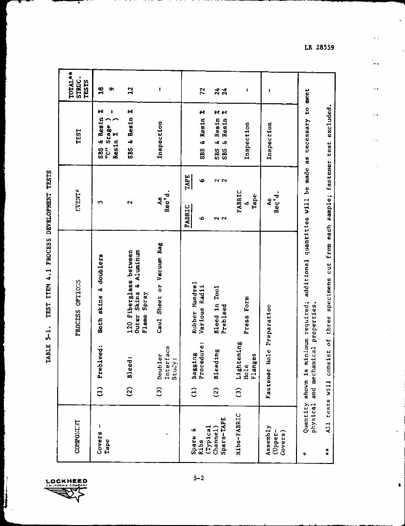
The detail plans for development of the manufacturing processes for the
ACA have been completed and are shown in Table 5-1. Process development will
be coordinated with design and ane.ysis to verify selection of fabrication
procedure.
LOCKHEEDCALIFORNIA COM AMV
LR 28559
I I IO E+ W r^I ^-1 r^ N N aJHrnH aJ
6
f t i 44 N N rTE aOr X41
^ ^ O Q C >> 7 m OW ar dl 47 O O O u
wa° u0.4 a a as d41 41
H a w ^a41
-a 4a .a (U v u u
as C asa00 ^ awa apa G uU) h N N rn U) H H y
`^41
aG
Wb aJ
%O N N
W41A
^ b H 4J bN
^
dd
0i v d H w •^ a04 44 OG 3
OGCU N N N rA
W ,^
u-r4
Cu
d
0o
o*o
Gw
.-1
u •^ cdpa~ O u
c^ b FA du+i
NGr0 4'J 1+ y •.•1 ^
H '0 O t4cw
W 00 G m L oC r0 H $4 u
u
O 44 41. i a 4011 °G o aC •u C Ti vi4 U) N d
w"'`n to w u •k
WW 14 4! 0) O b r-1 of u u a
.0 W 8 -4 ,G -H 41 .o m N 7 ^+ 4lO ^O ,go .0 14 41 4/ 41 H Q 41 N
00N O r0
>r4 O W U OG 00 P. p. C1 H O +^ar ^+
°00 a orr e 14
u ►+ oo •.4 ar cny4 O 00 O G C m 11 C u rnN G a w .^
r1 X414 b u 000 xLo
0 4^1 00 u 41 ,C 41 G cd C:j
"Oo O 41 00 .-a cc 14 u, = O
a (O C u rd 1+ .--I •H O r4 4) -H u ua a c„-1 N ca w as a x w a 4,
ar C 13
N M .-/ N M N o v3v v v v v v G4 W R1N
L yr4 u 41
U 4J r4 u
HpW H C rn
-+ Ed+ .-^i 1 .. a dO ►y+ i C
di^ ►1.
01at v
ra$.
(Aa C w y 0) a a1
O >^a >, ca cc .0 y a >
U U HIla.
- Uto 0444 W O.^. K
w 04 d U is Ir
yHNWH
H
adRi0wwU
°aa
S
H
HNWH
^•iILn
wa
H
LOCKHEED 5-2CAt$FD ANA COW/^tip
`q^

LR 28559
REFERENCES
1. Griffin, C. F., et al, "Advanced Composite Aileron For L-1011 TransportAircraft" Quarterly Technical Report #1, LR 28426, 23 January 1978.
LOCKHEED R-1CALIFORNIA COM%ANV