this document is for quick reference only,...
TRANSCRIPT
Panel1
Panel2
Panel16
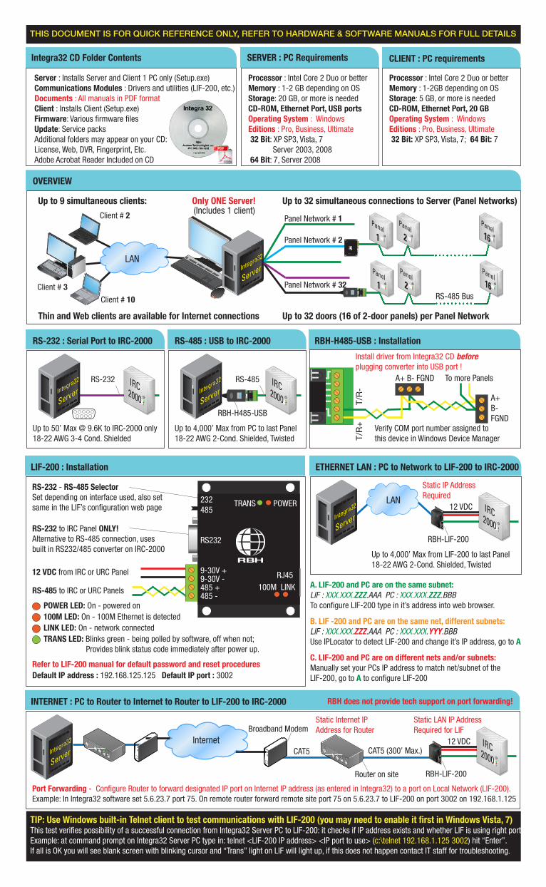
Panel Network # 1
Panel Network # 32RS-485 Bus
LAN
Client # 2
Client # 10
Integra
32
Server
Up to 9 simultaneous clients: Up to 32 simultaneous connections to Server (Panel Networks)
Up to 32 doors (16 of 2-door panels) per Panel Network
Only ONE Server!
IRC2000
Integra
32
Server
RS-485 : USB to IRC-2000
Up to 4,000’ Max from PC to last Panel 18-22 AWG 2-Cond. Shielded, Twisted
RBH-H485-USB
Integra
32
Server
RS-232 : Serial Port to IRC-2000
Up to 50’ Max @ 9.6K to IRC-2000 only18-22 AWG 3-4 Cond. Shielded
Integra
32
Server
ETHERNET LAN : PC to Network to LIF-200 to IRC-2000
Up to 4,000’ Max from LIF-200 to last Panel 18-22 AWG 2-Cond. Shielded, Twisted
RBH-LIF-200
LANIRC2000
Static IP AddressRequired
12 VDC
Thin and Web clients are available for Internet connections
OVERVIEW
Integra
32
Server
INTERNET : PC to Router to Internet to Router to LIF-200 to IRC-2000
RBH-LIF-200
IRC2000
Static LAN IP AddressRequired for LIF
12 VDCInternet
Static Internet IPAddress for Router
Router on site
Broadband Modem
CAT5 (300’ Max.)
Port Forwarding - Configure Router to forward designated IP port on Internet IP address (as entered in Integra32) to a port on Local Network (LIF-200). Example: In Integra32 software set 5.6.23.7 port 75. On remote router forward remote site port 75 on 5.6.23.7 to LIF-200 on port 3002 on 192.168.1.125
CAT5
RBH does not provide tech support on port forwarding!
Client # 3
CLIENT : PC requirementsSERVER : PC RequirementsIntegra32 CD Folder Contents
Server : Installs Server and Client 1 PC only (Setup.exe)Communications Modules : Drivers and utilities (LIF-200, etc.)Documents : All manuals in PDF formatClient : Installs Client (Setup.exe)Firmware: Various firmware filesUpdate: Service packsAdditional folders may appear on your CD:License, Web, DVR, Fingerprint, Etc.Adobe Acrobat Reader Included on CD
Processor : Intel Core 2 Duo or betterMemory : 1-2 GB depending on OSStorage: 20 GB, or more is neededCD-ROM, Ethernet Port, USB portsOperating System : WindowsEditions : Pro, Business, Ultimate 32 Bit: XP SP3, Vista, 7 Server 2003, 2008 64 Bit: 7, Server 2008
Processor : Intel Core 2 Duo or betterMemory : 1-2GB depending on OSStorage: 5 GB, or more is neededCD-ROM, Ethernet Port, 20 GBOperating System : WindowsEditions : Pro, Business, Ultimate 32 Bit: XP SP3, Vista, 7; 64 Bit: 7
TIP: Use Windows built-in Telnet client to test communications with LIF-200 (you may need to enable it first in Windows Vista, 7)This test verifies possibility of a successful connection from Integra32 Server PC to LIF-200: it checks if IP address exists and whether LIF is using right port.Example: at command prompt on Integra32 Server PC type in: telnet <LIF-200 IP address> <IP port to use> (c:\telnet 192.168.1.125 3002) hit “Enter”.If all is OK you will see blank screen with blinking cursor and “Trans” light on LIF will light up, if this does not happen contact IT staff for troubleshooting.
THIS DOCUMENT IS FOR QUICK REFERENCE ONLY, REFER TO HARDWARE & SOFTWARE MANUALS FOR FULL DETAILS
LIF-200 : Installation
RBH-H485-USB : Installation
Verify COM port number assigned to this device in Windows Device Manager
Install driver from Integra32 CD before plugging converter into USB port !
T/R
+
T
/R-
A+ B- FGND
A+B-FGND
To more Panels
RS-485 to IRC or URC Panels
12 VDC from IRC or URC Panel
RS-232 to IRC Panel ONLY!Alternative to RS-485 connection, uses built in RS232/485 converter on IRC-2000
RS-232 - RS-485 SelectorSet depending on interface used, also set same in the LIF’s configuration web page
Default IP address : 192.168.125.125 Default IP port : 3002Refer to LIF-200 manual for default password and reset procedures
TRANS LED: Blinks green - being polled by software, off when not; Provides blink status code immediately after power up.
POWER LED: On - powered on
LINK LED: On - network connected100M LED: On - 100M Ethernet is detected
A. LIF-200 and PC are on the same subnet:LIF : XXX.XXX.ZZZ.AAA PC : XXX.XXX.ZZZ.BBBTo configure LIF-200 type in it’s address into web browser.
B. LIF -200 and PC are on the same net, different subnets:LIF : XXX.XXX.ZZZ.AAA PC : XXX.XXX.YYY.BBBUse IPLocator to detect LIF-200 and change it’s IP address, go to A
C. LIF-200 and PC are on different nets and/or subnets:Manually set your PCs IP address to match net/subnet of the LIF-200, go to A to configure LIF-200
POWERTRANS232485
RS232
9-30V +9-30V -485 +485 -
100M LINKRJ45
USB
(Includes 1 client)Panel2
Panel16
Panel1
USB
Panel Network # 2
IRC2000
RS-485RS-232

For Support in U.S. Call : 201-663-9070All software and hardware manuals are included on Integra32 software CD in “Documents” folder!
Web site : www.rbh-access.com E-mail : [email protected]
THIS DOCUMENT IS FOR QUICK REFERENCE ONLY, REFER TO HARDWARE & SOFTWARE MANUALS FOR FULL DETAILS
SupportNOTE : System Data
ACCESS POINT : Configuration
RTEInstalled
DCInstalled
Lock by timer
Lockon door close
Door Forced
Door Held Open
Yes Yes Yes Yes Yes YesNo Yes Yes Yes No* YesNo No Yes No No No
RTE : Request to Exit, typically motion detector, crash bar, exit button - Shunts door contact and unlocks door for exitDC : Door Contact (a.k.a. door switch, DSM) - Monitors whetherthe door is opened or closedReader : Card, Fingerprint Reader with/or keypad with Wiegand Interface - Reads user credentials, PINs, etc.Lock : Electric strike, lock set, magnetic lock or any eclectically actuated device - secures an access pointAccess Point : Door, gate, turnstile, any point with secured access
RTE
R
DC
L
AccessPoint
* Will activate every time door is opened to exit, you can turn “Disable Door Forced Open” feature on
“ON State”Setting
OperationType
“Output Off”Relay is:
“Output On” Relay is:
N.O.Mark
N.C. Mark
Energized Fail-Secure Off On N.O. N.C.
De-energized Fail-Safe On Off N.C.* N.O.*
OUTPUTS:
Lock
* Functionality of relay polls will be reversed vs. printed marking
Relay Outputs (Marked ?N.0./?N.C./?C): Maximum rating 5A @ 30V, Dry, Form “C” relay
Voltage Outputs (Marked ?OC) : 100mA, -12VDC, for solid state devices only (LED, Piezo, etc.)N.O.N.C. COC
- +
+ -12V 0V
LED
Marking
INSTALL DIODE on DC powered locks! 1N4004 Diode installed at the lock will prevent damage to the controller. Please, use MOVs (metal oxide varistors) for AC powered locks.
1N4004 White stripe to +
NO RELAYS OR LOCKS! on OC outputs
INPUTS:
RTE : to keep door unlocked we need re-triggering of RTE input (Each trigger extends unlock timer)
DC : N.O. sensors are wired in parallel, N.C. sensors in series
Wiring : Up tp 1,000’ on 18-22 AWG 2-Cond. cable
Supervision type
Detects state changes:
Supervised secure
Supervised in alarm
None Yes No No.1 Resistor Yes Yes No2 Resistor Yes Yes Yes
MarkingCircuit Type Normally Closed Normally Open N. C. 1 Resistor N. O. 1 Resistor N. C. 2 Resistors N. O. 2 Resistors N. C. & N.O. 1 Resistor
Open Alarm Restore Alarm Trouble Trouble Trouble TroubleShort Restore Alarm Trouble Alarm Trouble Trouble Alarm
1K N/A N/A Restore Restore Restore Alarm Restore2K N/A N/A N/A N/A Alarm Restore N/A
Circuit State Default
1K Resistor Color code: Brown Black Red / Gold: 5% tolerance
READERS:
Function RBH HID AWID TerminalLED Brown Orange Brown GRN
Buzzer Blue Yellow Yellow BUZData 0 Green Green Green D0Data 1 White White White D1
Ground Black Black Black 0VPower Red Red Red 12V
Reader LED StatusRed Locked
Green Unlocked
Blinking “High Security” mode
Reader Sounder EventLong Beep Access Granted
Two short Beeps Access DeniedFour Beeps Mode Changed
Beeping DHO Warning or PIN request
Continuously On Door Forced or Door Held Open Alarm
See reader manual for actual color codes!
RED GRN BUZ D0 D1 0V 12V
To EXIT Reader
GRN RED BUZ D0 D1 SIG 0V 12V
To ENTRY Reader
To Controller
RBH-EXITRDR
EXITRDR : This module allows reporting of direction on doors
with readers installed on both sides, while using a single
reader port on the controller (RBH reader wiring shown)
Complete database is stored on the Server PC, cards and
settings are transferred to the panel during the download. Panel
retains this data and operates independently, sending events
to Server and receiving commands from it. It is not possible
to “upload” hardware configuration or card database from the
panel. Please configure Integra32 Server’s built in backup
function to preserve your data in case of PC failure!Please read our manuals before contacting technical support!
To access help (software manual) in Integra32 software hit F1 key!
Wiring : Up to 500’ Max from Reader to Panel on 18 AWG 6-Cond. Shielded Cable
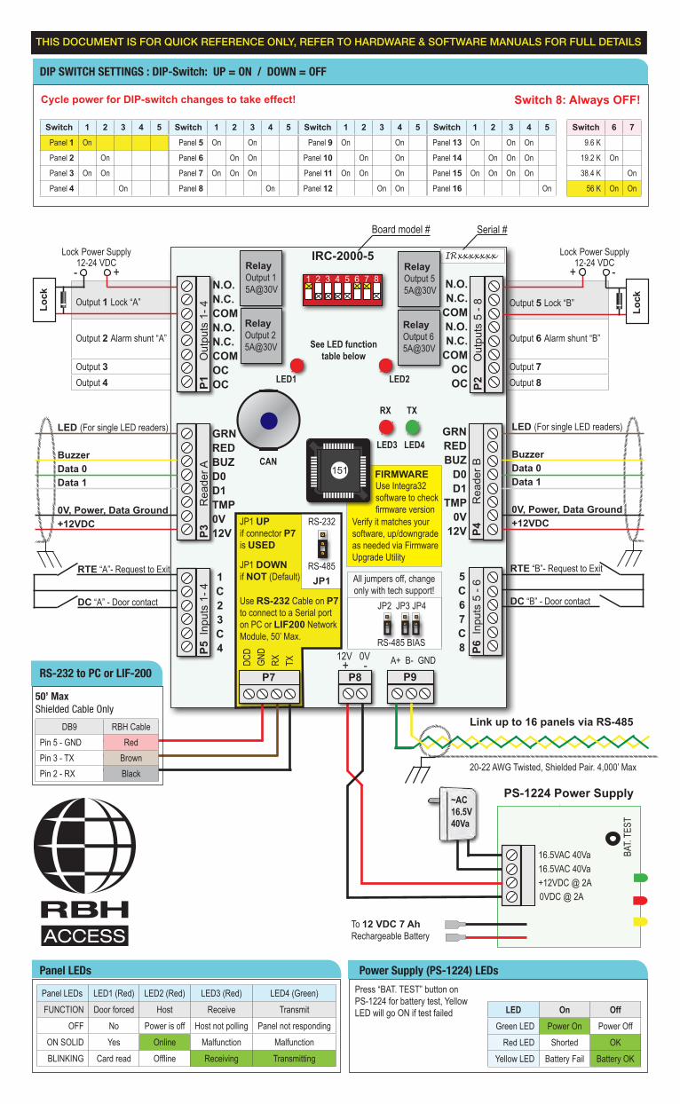
Output 1 Lock “A”
Output 2 Alarm shunt “A”
Output 3Output 4
Output 5 Lock “B”
Output 6 Alarm shunt “B”
Output 7Output 8
1 2 3 4 5 6 7 8
IRC-2000-5
151
JP1
JP2 JP3 JP4
P1
Out
puts
1- 4
P2
Out
puts
5 -
8
P3
R
eade
r A
P4
R
eade
r B
P5 I
nput
s 1-
4
P6 I
nput
s 5
- 6
P7 P8 P9
IRxxxxxxx
LED1 LED2
LED3 LED4
FIRMWARE
All jumpers off, change only with tech support!
RS-485 BIAS
RS-232
RS-485
JP1 UP if connector P7 is USED
JP1 DOWNif NOT (Default)
Use RS-232 Cable on P7 to connect to a Serial port on PC or LIF200 Network Module, 50’ Max.
Verify it matches your software, up/downgrade as needed via Firmware Upgrade Utility
Use Integra32 software to check firmware version
RX TX
See LED function table below
Board model # Serial #
Panel LEDs LED1 (Red) LED2 (Red) LED3 (Red) LED4 (Green)FUNCTION Door forced Host Receive Transmit
OFF No Power is off Host not polling Panel not respondingON SOLID Yes Online Malfunction MalfunctionBLINKING Card read Offline Receiving Transmitting
Cycle power for DIP-switch changes to take effect!
A+ B- GND
Link up to 16 panels via RS-485
To 12 VDC 7 AhRechargeable Battery
0VDC @ 2A+12VDC @ 2A
PS-1224 Power Supply
BAT.
TEST
Press “BAT. TEST” button on PS-1224 for battery test, Yellow LED will go ON if test failed
16.5VAC 40Va16.5VAC 40Va
+ -DCD
GND
RX TX
1C23C4
RTE “A”- Request to Exit
DC “A” - Door contact
RTE “B”- Request to Exit
DC “B” - Door contact
5C67C8
GRNREDBUZ
D0D1
TMP0V
12V
~AC16.5V40Va
LED (For single LED readers)
BuzzerData 0 Data 1
0V, Power, Data Ground+12VDC
LED (For single LED readers)
BuzzerData 0Data 1
0V, Power, Data Ground+12VDC
GRNREDBUZD0D1TMP0V12V
N.O.N.C.
COMN.O.N.C.
COMOCOC
Lock
Lock Power Supply12-24 VDC
N.O.N.C.COMN.O.N.C.COMOCOC
Lock
20-22 AWG Twisted, Shielded Pair. 4,000’ Max
RelayOutput 15A@30V
RelayOutput 25A@30V
RelayOutput 55A@30V
RelayOutput 65A@30V
- +Lock Power Supply
12-24 VDC
Switch 1 2 3 4 5
Panel 1 On
Panel 2 On
Panel 3 On On
Panel 4 On
Switch 1 2 3 4 5
Panel 9 On On
Panel 10 On On
Panel 11 On On On
Panel 12 On On
Switch 1 2 3 4 5
Panel 13 On On On
Panel 14 On On On
Panel 15 On On On On
Panel 16 On
Switch 1 2 3 4 5
Panel 5 On On
Panel 6 On On
Panel 7 On On On
Panel 8 On
Switch 6 7
9.6 K
19.2 K On
38.4 K On
56 K On On
Switch 8: Always OFF!
12V 0V
THIS DOCUMENT IS FOR QUICK REFERENCE ONLY, REFER TO HARDWARE & SOFTWARE MANUALS FOR FULL DETAILS
RS-232 to PC or LIF-200
Panel LEDs Power Supply (PS-1224) LEDs
DIP SWITCH SETTINGS : DIP-Switch: UP = ON / DOWN = OFF
+ -
DB9 RBH CablePin 5 - GND RedPin 3 - TX BrownPin 2 - RX Black
50’ Max Shielded Cable Only
P7 P8
CAN
LED On OffGreen LED Power On Power Off
Red LED Shorted OKYellow LED Battery Fail Battery OK