this document was designed for two-sided printing....
TRANSCRIPT

Table of Contents
i
CHAPTER 1 The FHDL Gate-Description Language _______________________1
1.1 Overview______________________________________________________________ 1
1.2 Simulating Circuits _____________________________________________________ 2
1.3 Creating and Using Subcircuits.___________________________________________ 3
1.4 Wire Declarations. ______________________________________________________ 4
1.5 The FHDL ROM Specification Language___________________________________ 5
1.6 The FHDL PLA Specification Language____________________________________ 6
1.7 Known Gate Types. _____________________________________________________ 71.7.1 Simple Gate Types __________________________________________________________ 71.7.2 And-or-inverts and Or-and-inverts. ______________________________________________ 71.7.3 Flip Flops. _________________________________________________________________ 81.7.4 Tristate Gates ______________________________________________________________ 91.7.5 Special Function Gates _______________________________________________________ 91.7.6 Functional blocks. ___________________________________________________________ 9
CHAPTER 2 Algorithmic State Machines ________________________________15
2.1 ASM State Declarations ________________________________________________ 15
2.2 ASM Condition Declarations ____________________________________________ 15
2.3 ASM Conditional Output Declarations ____________________________________ 16
2.4 State Machine Examples ________________________________________________ 17
CHAPTER 3 The ROM Preprocessor____________________________________21
3.1 Overview_____________________________________________________________ 21
3.2 Specifying Fields. ______________________________________________________ 22
3.3 Using Equates. ________________________________________________________ 22
3.4 Specifying ROM words. ________________________________________________ 23
3.5 Required Fields _______________________________________________________ 24
3.6 Complex Commands ___________________________________________________ 25
3.7 ROM addresses. _______________________________________________________ 25
3.8 Adding New Opcodes___________________________________________________ 26
3.9 ROM Output _________________________________________________________ 26
3.10 ROMs With Multiple Word Formats ____________________________________ 27
3.11 Include Statements____________________________________________________ 29
3.12 Running the preprocessor ______________________________________________ 29
3.13 Using ROMs _________________________________________________________ 30
CHAPTER 4 The PLA Preprocessor ____________________________________31
4.1 Overview_____________________________________________________________ 31
4.2 Specifying Fields. ______________________________________________________ 32

Table of Contents
ii
4.3 Using Equates. ________________________________________________________ 32
4.4 Specifying the Value of AND and OR Plane Fields.__________________________ 33
4.5 Required OR Plane Fields_______________________________________________ 35
4.6 Complex Commands ___________________________________________________ 35
4.7 Complex Conditions____________________________________________________ 36
4.8 Limiting the Number of Wordlines _______________________________________ 36
4.9 Adding New Opcodes___________________________________________________ 36
4.10 The Begin and End Statements__________________________________________ 37
4.11 Grouping Input and Output Fields ______________________________________ 37
4.12 Multiple OR Plane Formats ____________________________________________ 38
4.13 Include Statements____________________________________________________ 40
4.14 Running the preprocessor ______________________________________________ 40
4.15 Using PLAs __________________________________________________________ 41
CHAPTER 5 The MACRO Preprocessor _________________________________43
5.1 Overview_____________________________________________________________ 43
5.2 A Simple Macro Definition ______________________________________________ 44
5.3 A More Complicated Example ___________________________________________ 45
5.4 Accessing The Argument List____________________________________________ 48
5.5 Generating Net Names__________________________________________________ 49
5.6 Function Calls ________________________________________________________ 51
5.7 Generating Partial FHDL Statements _____________________________________ 52
5.8 The else-if Construct ___________________________________________________ 53
5.9 Accessing Attributes ___________________________________________________ 54
5.10 Arithmetic and Logical Expressions. _____________________________________ 54
5.11 String Handling Functions._____________________________________________ 55
5.12 List Handling Features ________________________________________________ 56
5.13 Type Conversion Functions ____________________________________________ 57
5.14 Redirecting Output ___________________________________________________ 58
5.15 Creating Macro Libraries______________________________________________ 60
5.16 Including Text _______________________________________________________ 60
5.17 A Word on Format____________________________________________________ 61
5.18 Executing the Preprocessor_____________________________________________ 63
5.19 Macro Statement Summary ____________________________________________ 655.19.1 Operand-Type Designators __________________________________________________ 655.19.2 Statements _______________________________________________________________ 65

Table of Contents
iii
5.20 Macro Function and Built-in Variable Summary __________________________ 675.20.1 Operand-Type Designators __________________________________________________ 675.20.2 Functions and Variables ____________________________________________________ 67
5.21 Macro Operator Summary _____________________________________________ 695.21.1 Operand-Type Designators __________________________________________________ 695.21.2 Operands ________________________________________________________________ 69
5.22 Macro Processor Keywords ____________________________________________ 72
5.23 Macro Operator Precedence____________________________________________ 73
CHAPTER 6 The Test Driver Language _________________________________75
6.1 Introduction __________________________________________________________ 75
6.2 The Format of the Language ____________________________________________ 76
6.3 Expressions ___________________________________________________________ 77
6.4 Statements____________________________________________________________ 786.4.1 The variable statement ______________________________________________________ 786.4.2 The go statement ___________________________________________________________ 786.4.3 The expression statement ____________________________________________________ 786.4.4 The read statements_________________________________________________________ 796.4.5 The write statements ________________________________________________________ 806.4.6 The monitor statements ______________________________________________________ 806.4.7 The if statement____________________________________________________________ 816.4.8 The while statement_________________________________________________________ 836.4.9 The for statement___________________________________________________________ 836.4.10 Break and continue statements _______________________________________________ 846.4.11 The message statement _____________________________________________________ 846.4.12 The error statement ________________________________________________________ 846.4.13 The clock statement________________________________________________________ 856.4.14 The count statement _______________________________________________________ 856.4.15 On conditions ____________________________________________________________ 856.4.16 The include statement ______________________________________________________ 866.4.17 Invoking the Interactive Command Interpreter ___________________________________ 866.4.18 Dynamic Output Processors _________________________________________________ 876.4.19 The quit statement _________________________________________________________ 87
6.5 The Interactive Command Interpreter ____________________________________ 876.5.1 The help command _________________________________________________________ 886.5.2 The show commands________________________________________________________ 886.5.3 Interactively specified macros_________________________________________________ 896.5.4 The remove statement _______________________________________________________ 90
CHAPTER 7 The Test Data Generator __________________________________91
7.1 Introduction __________________________________________________________ 91
7.2 Productions___________________________________________________________ 92
7.3 The Rules for Forming Strings___________________________________________ 92
7.4 More Types of Productions______________________________________________ 94
7.5 More on Non-Terminals ________________________________________________ 95
7.6 Techniques for Systematic Generation of Data _____________________________ 96

Table of Contents
iv
7.7 Running out of Choices _________________________________________________ 98
7.8 Variables _____________________________________________________________ 99
7.9 Creating a Data Generator _____________________________________________ 101
7.10 Advanced Features___________________________________________________ 102
7.11 Action Routines _____________________________________________________ 104
7.12 State Variables ______________________________________________________ 106
7.13 Data-Generation Subroutines__________________________________________ 106
7.14 Experimental Features _______________________________________________ 108
7.15 White Space and Comments ___________________________________________ 109
7.16 Conclusion _________________________________________________________ 110
7.17 Dgl Keywords and Reserved Characters_________________________________ 111
CHAPTER 8 The USF WSI Floorplanner_______________________________113
8.1 Introduction _________________________________________________________ 113
8.2 Drawing Modes ______________________________________________________ 114
8.3 Menu Commands_____________________________________________________ 1168.3.1 File Commands ___________________________________________________________ 1168.3.2 Edit Commands___________________________________________________________ 1178.3.3 The Param Menu__________________________________________________________ 1188.3.4 The Array Menu __________________________________________________________ 122
8.4 The Scroll Bars_______________________________________________________ 123
8.5 Selecting, Moving, and Resizing Objects__________________________________ 123
8.6 Conclusion __________________________________________________________ 124
CHAPTER 9 The Wave-Form Generator________________________________125
9.1 Introduction _________________________________________________________ 125
9.2 Invoking The Generator _______________________________________________ 125
9.3 Scrolling ____________________________________________________________ 128
9.4 The Command Bar ___________________________________________________ 128
9.5 The Mode Bar________________________________________________________ 129
9.6 Shutting Down The Display ____________________________________________ 129
9.7 Conclusion __________________________________________________________ 129
CHAPTER 10 The Vector Display Program _____________________________131
10.1 Introduction ________________________________________________________ 131
10.2 Program Options ____________________________________________________ 132
10.3 Processing of Command Line Arguments________________________________ 133
10.4 Environment Variables _______________________________________________ 134

Table of Contents
v
10.5 Examples___________________________________________________________ 13410.5.1 Example 1 ______________________________________________________________ 13510.5.2 Example 2 ______________________________________________________________ 13610.5.3 Example 3 ______________________________________________________________ 13710.5.4 Example 4 ______________________________________________________________ 13810.5.5 Example 5 ______________________________________________________________ 14010.5.6 Example 6 ______________________________________________________________ 14110.5.7 Example 7 ______________________________________________________________ 14210.5.8 Example 8 ______________________________________________________________ 142
10.6 Conclusion _________________________________________________________ 144
Index_____________________________________________________________145

1
CHAPTER 1
The FHDL Gate-Description Language
1.1 OverviewThe Florida Hardware Design Language (FHDL) resembles assembly language in that
each statement has a label field, an operation code, and a list of operands. The label field,which is optional, starts at the first character of a statement and ends with a colon (:). Theoperation code must always be present and must be preceded by one or more spaces ortabs. If a label is present the operation code follows the label. The operand list, which isalso optional, follows the operation code, and must be separated from the operation codeby one or more spaces or tabs. Every statement must be followed by a newline character(return key) or a semicolon (;).
To translate a logic diagram such as the following into FHDL you must first chooseunique names for each of the connections.
A
B
CD
E
F
G
HG1
G2
G3
G4
In this example the names A-H have been chosen for the connections. Next you mustchoose a unique name for the circuit (for this example we will choose "example1.") Youbegin your circuit description with the following statement.
example: circuit

Chapter 1 The FHDL Gate Description Language
2
Next you must make a list of the primary inputs and outputs of the circuit. In theexample above, A, B, C, and D are primary inputs while E is a primary output. An"input" statement is used to declare primary inputs, while an "output" statement is used todeclare primary outputs. The following statements would be used for our example.
inputs: A, B, C, Doutputs: E
Next you must describe each gate using an appropriate statement. In our example, one"not" statement, two "and" statements, and one "or" statement will be required. Thesestatements do not require labels, but it is a good idea to use them anyway. The gates ofour example would be written as follows.
g1: not A,Hg2: and (H,B),Fg3: and (C,D),Gg4: or (F,G),E
The order of the statements (including the input and output statements) is arbitrary.The operand list of a statement that describes a gate has two parts. The first part lists thegate's inputs while the second part lists the gate's outputs. If there is more than one input,the list of inputs must be enclosed in parentheses. Similarly if there is more than oneoutput, the list of outputs must be enclosed in parentheses.
Finally you must end your description with an "endcircuit" statement. The entiredescription is given below.
example1: circuitinputs A,B,C,Doutputs E
g1: not A,Hg2: and (H,B),Fg3: and (C,D),Gg4: or (F,G),E
endcircuit
FHDL "knows" about many different kinds of gates, which are listed in Appendix A.In most cases the order of the inputs and outputs is significant.
1.2 Simulating CircuitsPut your circuit description into a file that ends with the string ".ckt". The rest of the
file name should match the name of your circuit. For the example given in the lastsection, you would use the file name "example1.ckt". Once this file is created, run thefollowing UNIX command
fhdl example1.ckt
If you haven't made any errors, this will give you a file named "example1.c". Youmust then run the following command.
cc example1.c -o example1

Chapter 1 The FHDL Gate Description Language
3
The program "example1" will simulate your circuit, but first you must create a filenamed "example1.vec" which contains the test vectors for your circuit. You simulateyour circuit using the following command.
example1 <example1.vec
Each test vector represents one set of inputs for your circuit. You will get one set ofoutputs for each set of inputs. Each set of inputs must appear on a separate line. Thevalues for each of the primary inputs must be listed in the same order as they appear onthe "input" statement. A ".vec" file for our example is illustrated below.
0,1,0,01,1,0,10,0,0,01,1,1,1
This file will produce the outputs:
1001
Blank lines and lines beginning with asterisks are treated as comments in a ".vec" file.These lines will be copied into the output file to assist you in reading the output.
More sophisticated users will wish to make use of additional features of FHDL thatare described in other memoranda. Features currently available are ROM and PLApreprocessors, the FHDL macro processor, and the FHDL driver language. To invoke allFHDL functions, replace the fhdl command given above with the following command.
fhdl -n example1.ckt
This command has the added benefit of performing the "cc" command automaticallyfor you. You may use this version of the command even if you do not use any of theadditional FHDL features, although compilation time will be somewhat longer.
1.3 Creating and Using Subcircuits.In addition to the known gate types, you can create new ones by declaring them as
circuits. For example, suppose you want to create a two-input "NAND" with one active-low input and one active-high input. You could do this as follows.
xnand: circuitinputs A,Boutputs Cnot A,ABARnand (ABAR,B),Cendcircuit
You may now use xnand as a gate in any other circuit in the same file. When youhave several circuits in the same file, the first is treated as the main circuit and all others

Chapter 1 The FHDL Gate Description Language
4
are treated as subcircuits. To use the xnand subcircuit, include a statement similar to thefollowing in some other circuit.
gtest: xnand (Q,R),S
You may use a subcircuit any number of times.
1.4 Wire Declarations.A signal may be declared to be active low by using the following statement.
wire A,type=active_low
The signal A should appear as a connection in some gate of the circuit. Similarly, asignal can be declared as unconnected by using the following statement.
wire B,type=no_connect
Signals can be declared as permanently one or permanently zero by using one of thefollowing statements.
zero A,E,Fone B,C
A signal can be declared to be a bus, which will cause it to be treated as a collectionof independent signals. This option makes coding easier and more readable and makessimulations run faster. To declare a signal as a bus, use the following statement.
wire A,width=10
The width may be anything from 1 to 32. When a bus is fed into an ordinary gate, thegate will be replicated to match the width of the signal. Different gates treat busesdifferently, so check the appendix first.
The collect, distribute, and expand statements are used to connect signals and otherbuses to a bus. The collect statement is used to feed a collection of signals into a bus. Anexample of a collect statement is given below.
collect (a,b,c),d
The signals a, b, and c are "collected" together into the bus d. The three signals mayhave any width, but the sum of the widths of the inputs cannot
be larger than the width of the output. The "position" parameter can be used to placea, b, and c at specific points within d, as illustrated by the following statement.
collect (a,b,c),d,position=(1,3,5)
Assuming that the widths of a, b, and c are all 1, this statement inserts a, b, and c intothe odd numbered positions of d. Note that the collect statement creates the bus d, soyou cannot use several collect statements to build a bus. You have to do it all in onestatement. The "position" parameter treats the leftmost bit of the bus as position zero.No overlap check is done for position parameters, so you must be careful.
The "distribute" statement is the reverse of the collect statement. It is used todistribute the signals in a bus to several output signals. The following statementdistributes the signals in a bus a to two outputs x and y.

Chapter 1 The FHDL Gate Description Language
5
distribute a,(x,y)
The leftmost bits of "a" are fed to "x", and the next bits are fed to "y." The width of"a" must be greater than or equal to the sum of the widths of "x" and "y." The "position"parameter can be used on the distribute statement in order to specify the location withinthe input where the bits of an output must start. For example, the following statementextracts the high and low order bits from a 16-bit bus.
distribute abus,(highbit,lobit),position=(0,15)
The "expand" statement fans a width 1 signal out into every position of a bus.Assume that the width of the signal a is 1 and the width of signal b is 5. Then thefollowing two statements are equivalent.
expand a,bcollect (a,a,a,a,a),b
1.5 The FHDL ROM Specification LanguageThe FHDL ROM specification language allows one to specify the number of address
bits, the number of bits per word, and the contents of each word. See Chapter III for amore sophisticated ROM specification language. The contents of a word must bespecified in hexadecimal. If a ROM of constants is to be created, the FHDL ROMspecification language may be preferable to the ROM preprocessor language.
In FHDL, a ROM is a circuit containing only "romword" statements and input/outputdeclarations. The following is an example.
rom1: circuitinputs addressoutputs romoutwire address,width=8wire romout,width=16romword 7fferomword 8000romword 0001romword 07ffendcircuit
As this example shows, each "romword" instruction supplies the value for one wordof the ROM. ROM addresses are assigned consecutively starting with zero. The wordvalues must be specified in hexadecimal, without the "0x" prefix. There must be exactlyone input, and the width of the input must be explicitly declared to be the number ofaddress bits in the ROM. There must be at least one output, and each output should havea declared width. The maximum width for any input or output is 32. ROMs with wordlength greater than 32 may be constructed using multiple outputs. When a ROM hasmultiple outputs, each "romword" instruction must specify the value of each output asillustrated below.

Chapter 1 The FHDL Gate Description Language
6
abc: circuitinputs addressoutputs o1,o2,o3wire address,width=8wire o1,width=4wire o2,width=4wire o3,width=4romword a,b,cromword d,e,fromword 0,1,2romword 3,4,5endcircuit
As both examples illustrate, it is not necessary to specify a value for each word in theROM. When the FHDL compiler generates simulation code for the rom, the inputaddress is checked against the address of the last word specified, and if the input addressis larger, a run-time error message is issued. This provides a convenient method fordetermining whether invalid ROM addresses are being issued.
1.6 The FHDL PLA Specification LanguageThe FHDL PLA specification language allows one to specify the number of inputs,
the number of outputs, and the contents of the AND and OR plane portion of eachwordline. See Chapter IV for a more sophisticated PLA specification language. Thecontents of the AND plane must be specified in trinary where 0 and 1 represent a bit testagainst the specified value and x represents don't care. The trinary string is normallyenclosed in quotes. The contents of the OR plane must be specified in hexadecimal.
In FHDL, a PLA is a circuit containing only "plaword" statements and input/outputdeclarations. The following is an example.
pla1: circuitinputs a1outputs plaoutwire a1,width=8wire plaout,width=16plaword "0111xxxx",7ffeplaword "x010x01x",8000plaword "011x0xxx",0001plaword "0111101x",07ffendcircuit
As this example shows, each "plaword" instruction supplies the AND and OR planevalues for one wordline of the PLA. OR plane values must be specified in hexadecimal,without the "0x" prefix. There must be at least one input and at least one output, and eachinput and output should have a declared width. The maximum width for any input oroutput is 32. PLAs with more than 32 inputs and outputs may be constructed usingmultiple inputs and outputs. When a PLA has multiple inputs and outputs, each"plaword" instruction must specify the value of each input and each output as illustratedbelow.

Chapter 1 The FHDL Gate Description Language
7
abc: circuitinputs a1,a2outputs o1,o2,o3wire a1,width=2wire a2,width=2wire o1,width=4wire o2,width=4wire o3,width=4plaword "xx","01",a,b,cplaword "0x","x0",d,e,fplaword "1x","x1",0,1,2plaword "11","xx",3,4,5endcircuit
As both examples illustrate, it is not necessary to specify a value for each set of inputconditions. When the FHDL compiler generates simulation code for the pla, the inputcondition is checked against the conditions specified for each wordline. If no wordline isselected by the condition, a run-time error message is issued. This provides a convenientmethod for determining whether invalid PLA conditions are being issued.
1.7 Known Gate Types.
1.7.1 Simple Gate Typesandornandnornotxorxnor
All of these gates may be used with buses as long as the widths of all inputs andoutputs are identical. The gates replicate themselves for each element of the bus.Replicated gates typically simulate much faster than individually specified gates. Allgates except "not" may have an arbitrary number of inputs, but must have at least twoinputs. The "not" gate must have one input. All of these gates must have one output.Since all of these gates represent symmetric functions, the order of the inputs is notsignificant.
1.7.2 And-or-inverts and Or-and-inverts.aoi...oai...
These actually represent families of gates rather than a single gate. The aoi or oaiprefix must be followed by a string of digits, which define the structure of the gate. Foran aoi, each digit represents one AND gate, and the value of the digits defines the number

Chapter 1 The FHDL Gate Description Language
8
of inputs for the AND gate. The outputs of all AND gates are ORed together and theoutput is inverted. The oai works in a similar fashion. Only digits 1-9 may be used, 0 isunacceptable. There is no restriction on the number or order of the digits, but in practiceone should conform to the conventions of existing cell libraries. The inputs are clusteredfrom right to left in accordance with the order of the digits in the digit string. Thefollowing is an example of an aoi gate.
aoi212 (a1,a2,b1,c1,c2),out
This gate could be translated into ands ors and nots as follows.
and (a1,a2),x1and (c1,c2),x2or (x1,b1,x2),x3not x3,out
1.7.3 Flip Flops.rsffdffdff1dff2dff3dff4jkffjkff1jkff2jkff3jkff4tfftff1tff2tff3tff4
All flip flops may have one or two outputs. If one output is specified, it is the normaluncomplemented output. If two outputs are specified, the first is the uncomplementedoutput and the second is the complemented output. The two outputs must have the samewidth.
The rs flip flop (rsff) has two inputs, set and reset.The d flip flop (dff) has two inputs, d and clock.The jk flip flop (jkff) has three inputs, j, k, and clock.The t flip flop has two inputs toggle and clock.For these flip flops, the inputs are all active high must be specified in the order given.Flip-flops of the form dff1, jkff1, and tff1 are CMOS variations on the basic flip-
flops. In addition to the inputs already mentioned, each of these must also have aninverted-clock input. Flip-flops ending in 1 have no other inputs in addition to theinverted clock. Those ending in 2 have an active-high asynchronous set, those ending in

Chapter 1 The FHDL Gate Description Language
9
3 have an active-low asynchronous reset, and those ending in 4 have both. The additionalinputs follow the clock in the following order as appropriate <inverted-clock>,<set>,<reset>.
If the outputs of a flip flop are buses, the gates replicate themselves for each bit in thebus. The width of an input must be 1 or identical to the width of the outputs. If thewidth of an input is 1, the input is fanned out to all of the replicated gates. Otherwise, theindividual bits in the input are routed to the individual flip flops. This replication of gatesis logical not physical, so replicated gates usually simulate much faster than a collectionof individually specified gates.
1.7.4 Tristate Gatestbufitgate
These gates are similar in function. The first is an inverting tristate buffer, while thesecond is a non-inverting transmission gate. When laid out, the first will haveamplification, the second will not. The inputs to these gates are identical. The first inputis the D input while the next two are clock and inverted clock. The clock is active high.If the clock is active, the tbufi acts as an inverter while the tgate copies its input to itsoutput. If the clock is not active, the output of the gate does not change. (This allowswired-or connections to work properly.)
1.7.5 Special Function Gatesexpandcollectdistributehlcv
The "expand," "collect," and "distribute" gates are described in detail in the text ofthis document. The "hlcv" gate is used to convert an active-high signal to an active-lowsignal and vice versa. No logic function is performed, the value of the output is identicalto the value of an input. However, the input can be declared as active-high and the outputas active-low, or vice versa. This allows proper functioning of gates that are sensitive toactive-high, active-low declarations without introducing unnecessary logic.
1.7.6 Functional blocks.muxdemuxdecoderencodercomparatoradderramregistercounteralu

Chapter 1 The FHDL Gate Description Language
10
1.7.6.1 Mux format
mux (inputs,control),output
The control input may be either a set of n width-1 inputs or a single width-n bus. If
the inputs and outputs are all the same width, there must be one output and 2n inputs. Inthis case, the MUX is replicated for each bit in the output. If the inputs and outputs arenot all the same width, then the output must be width 1, there must be only one input, and
that must be a bus of width 2n.
1.7.6.2 Demux format
demux (input,control),(outputs)
The control input may be either a set of n width-1 inputs or a single width-n bus. If
the inputs and outputs are all the same width, there must be one input and 2n outputs. Inthis case, the MUX is replicated for each bit in the input. If the inputs and outputs are notall the same width, then the input must be width 1, there must be only one output, and
that must be a bus of width 2n.
1.7.6.3 Decoder format
decoder (control),(outputs)
The control input may be either a set of n width-1 inputs or a single width-n bus. If
the outputs are all of width one, there must be 2n of them. Otherwise there must be a
single output of width 2n.
1.7.6.4 Encoder format
encoder (control),(outputs)
The control input may be either a set of 2n width-1 inputs or a single width-2n bus. Ifthe outputs are all of width one, there must be n of them. Otherwise there must be a singleoutput of width n. This is a priority encoder.
1.7.6.5 Comparator format
comparator (leftin,rightin),(output)
Either leftin or right in may be n width-1 signals or a width-n bus. The output mustbe three width one signals or a width-3 bus. The first output is active for leftin<rightin,the second for leftin=rightin and the third for leftin>rightin.
1.7.6.6 Adder format
adder (leftin,rightin),(output)
Either leftin or right in may be n width-1 signals or a width-n bus. The output mayalso be n width-1 signals or an width-n bus. The default is to have no carry in and nocarry out. The presence of a carry-in is specified by the attribute "carry=in" while thepresence of a carry out is specified by the attribute "carry=out." The presence of both is

Chapter 1 The FHDL Gate Description Language
11
specified by the attribute "carry=(in,out)." If carry in is present, it must follow "rightin"in the input list and must have a width of one. Similarly carry out follows "output" in theoutput list and must have a width of one. The following is an example with both.
adder (leftin,rightin,ci),(output,co),carry=(in,out)
1.7.6.7 Ram format
ram (address,datain,readwrite),(dataout)
Address, datain and dataout must be buses. Datain and dataout must have the samewidth. Readwrite must be a width 1 signal which is zero for read and one for write. Thesize of the ram depends on the width of the address.
1.7.6.8 Register format
register (datain,load,controlsignals,clock),(dataout,statussignals),options
Datain and dataout may be a set of n width-1 signals or one width-n bus. Options areof the form option_name=option or option_name=(opt1,opt2,...). The options determinethe content of the controlsignals and statussignals fields. The available options are asfollows.
control=clear (include an asynchronous clear) right (include a shift-right signal) left (include a shift-left signal) set (include an asychronous set)
These signals appear in the controlsignals field in the order specified. If the controloption is not used, there are no signals in the controlsignals field.
status=all_zero (include a zero status output) all_ones (include a set status output)
These signals appear in the statussignals field in the order specified. If status is notspecified, there are no signals in the statussignals field.
clock=yes (create a clocked register) no (create an async-load register)
Default is "yes." If "yes" is specified, the clock is always the last input in the inputlist.
serial=right (Include a right serial input) left (Include a left serial input)
This option adds serial inputs to the controlsignals field. These will appear in theorder specified, either at the begining of the controlsignals field or at the end, dependingon whether the status or control input is specified first. The right serial input is used forleft shifts and the left serial input is used for right shifts.

Chapter 1 The FHDL Gate Description Language
12
1.7.6.9 Counter format
counter (datain,controlsignals),(dataout,statussignals),options
The datain and dataout, if present, must be a collection of n width-1 signals, or onewidth-n bus. The options are the same format as those for registers. The availableoptions are as follows.
control=set clear count_up count_down load
Each option causes one control signal to be included in the controlsignals field in theorder specified. If "load" is not included, then "datain" is implicitly omitted. If bothcount_up and count_down are omitted, the counter will count up with each clock pulse (ifthe clock is present) or with each input vector (if there is no clock).
status=all_zero all_ones
This is the same as for registers.
clock=yes no
This is the same as for registers.
dataout=yes no
If dataout=no is specified, the dataout field will be omitted. Default is dataout=yes.
width=<<number>>
If both datain and dataout are missing, you must use this parameter to indicate howmany bits are in the counter.
type=binarydecade
The normal (and default) type of counter is a binary counter. A decade counter countsfrom zero to nine and back to zero, and must have a width of 4.
1.7.6.10 ALU format
alu(Ainput,Binput,control),(output,statussignals),options
Ainput, Binput, and output may each be n width-1 signals or one width-n bus.Control may be from four to six width-1 signals or a bus of width from four to six. The

Chapter 1 The FHDL Gate Description Language
13
size of the control field depends on the options. Options have the same format as forregisters and counters. The options are as follows.
control=carryin cenable
These options increase the size of the control field from a default of four to either fiveor six depending on whether one control option or two has been specified. The exactposition of the carryin and carry enable signals really doesn't matter since the ALUsimulator considers the control field to be one n-bit field.
status=all_zero all_ones carryout
These options add status signals to the statussignals field.
function=(number, name , ... )
This parameter indicates which function is selected for each value of the controlinputs. The control field is treated as an n-bit binary number where n is either 4, 5, or 6.Function name must be one of the following. During simulation, when the control fieldhas the value "number" the function indicated by "name" is performed on "Ainput" and"Binput" and placed into "output." The available functions are listed in the followingtable.
Specification Function
one 1
zero 0
a a
b b
not_a a'
not_b b'
and a&b
or a|b
xor (a&b')|(a'&b)
nand a'|b'
nor a'&b'

Chapter 1 The FHDL Gate Description Language
14
Specification Function
xnor (a&b)|(a'&b')
a_and_not_b a&b'
a_or_not_b a|b'
not_a_and_b a'&b
not_a_or_b a'|b
subtract a-b
add a+b
incr_a a+1
incr_b b+1
decr_a a-1
decr_b b-1
b_minus_a b-a
15
CHAPTER 2
Algorithmic State Machines
The statements of an algorithmic state machine description have the same format asthose of an FHDL statement (see Chapter I, section 1). The first statement of analgorithmic state machine is a "circuit" statement that gives the name of the circuit. Thelast statement is an "endcircuit" statement. The body of an ASM is declared using thestatements "asm_state," "asm_test," and "asm_cond". These statements cannot be mixedwith FHDL gate declarations. (However, a file may contain several different types ofcircuits.) An "asm_state" statement is used to declare each state of a state machine, the"asm_test" statement is used to declare tests for conditional state transfers and conditionaloutputs, while the "asm_cond" statement is used to declare conditional outputs.
2.1 ASM State DeclarationsThe format of the "asm_state" statement is as follows.
asm_state state_name,next_statement,o=(state_outputs)
The field "state_name" gives a unique name to the state. The "state_outputs" field is alist, separated by commas of the outputs that must be unconditionally asserted when themachine is in this state. Any number of outputs may be specified. If only one output isspecified, the parens may be omitted. The "next_statement" field is the name of thestatement that follows this statement in the flow chart of the state machine. If themachine transfers unconditionally to a new state, then "next_statement" will be the nameof the new state. If the state transfers to two or more states depending on certainconditions, then "next_statement" will be the name of an "asm_test" statement.
2.2 ASM Condition DeclarationsThe "asm_test" statement is used to cause conditional state transfer, and to activate
conditional outputs. The format of the "asm_test" statement is as follows.
asm_test test_name,(next_statements),c=(conditions)

Chapter 2 Algorithmic State Machines
16
Any number of conditions may be specified, and each condition may have the valuetrue or false. The list of "next_statements" must contain one statement name for each
combination of condition states. That is, if n conditions are specified, then 2n
"next_statement" names must be specified. If one condition is specified, then the "false""next_statement" name must come first, and the "true" "next_statement" name must comesecond. In general, you can determine the order of the "next_statement" names bytreating the combination of condition values as a string of binary digits, with zerorepresented by false and one represented by true. The "next_statement" names must bespecified in ascending numeric sequence. Thus for two conditions, the "next_statement"names must be specified in the order FF, FT, TF, and TT.
Each statement name in the "next_statement" list must be the name of anotherstatement. An "asm_state" statement is named to create a conditional state transfer, an"asm_cond" statement to create a conditional output, and another "asm_test" statement isnamed to create a chain of tests.
2.3 ASM Conditional Output DeclarationsConditional outputs are created by using "asm_cond" statements. The format of an
"asm_cond" statement is given below.
asm_cond statement_name,next_statement,o=(outputs)
The "statement_name" field is a unique name that is assigned to the statement. The"next_statement" field is the name of the statement that follows this one in the flow chartof the circuit. The "outputs" field is a list of outputs that must be activated when theconditional output is activated. This statement should follow one or more "asm_test"statements. The "next_statement" field may name an "asm_state," an "asm_test," oranother "asm_cond" statement.
All outputs that appear on "asm_state" and "asm_cond" statements must be declaredas primary outputs of the circuit containing them. Furthermore all conditions that appearon an "asm_test" statement must be declared as primary inputs of the circuit. All primaryinputs and outputs of an ASM must have width 1, although they may be declared asactive-high or active-low. When an active-low output is "activated" its value is set tozero, otherwise it is set to one. When an active-high output is activated, its value is set toone otherwise it is set to zero. If an output is not mentioned in a state, it will be set to itsinactive value.
For active-high conditions, zero is treated as false and one is treated as true. Foractive-low conditions, zero is treated as true and one is treated as false.
You must be careful that each statement belongs to only one state. In other words itmust not be possible to go from two "asm_state" statements to a particular "asm_test" or"asm_cond" statement without going through another "asm_state." You will get severalerror messages if you violate this rule. (If you violate this rule it is impossible to build acircuit corresponding to the ASM specification, even if you could manage to simulate itin software.)

Chapter 2 Algorithmic State Machines
17
2.4 State Machine ExamplesTo illustrate the use of FHDL to code simple state machines, consider the following
example.
A B
C D
x1
x2
x3
x4
x5
This statemachine would be coded in FHDL as follows.
example2: circuitinputs x1,x2,x3,x4,x5outputs o1,o2,o3,o4asm_state A,testa,o=o1asm_test testa,(A,B,C,B),c=(x1,x4)asm_state B,testb,o=o2asm_test testb,(B,A),c=x5asm_state C,testc,o=o3asm_test testc,(C,D),c=x2asm_state D,testd,o=o4asm_test testd,(D,B),c=x3endcircuit
The following is a more complicated example.

Chapter 2 Algorithmic State Machines
18
This example would be coded in FHDL as follows.
example3: circuitinputs x1,x2,x3outputs o1,o2,o3,o4,o6,o6asm_state A,test1,o=o1asm_test test1,(cout1,C,C,cout2),c=(x1,x2)asm_cond cout1,B,o=o2asm_cond cout2,D,o=o3asm_state B,test2,o=o4asm_test test2,(B,A),c=x3asm_state C,A,o=(o5,o6)asm_state D,Aendcircuit
If an state machine requires a clock, it must be specified on the "circuit" statement,and in the list of primary inputs. The following is a modified version of the first twostatements of example3, to include a clock.
example3: circuit clock=iclkinputs x1,iclk,x2,x3
If it is necessary for the current state of the state machine to be visible to other logic inyour design, place the name "current_state" in the list of primary outputs. The followingis a modification of example3 to include a clock and current_state output.
example3: circuit clock=iclkinputs x1,x2,x3,iclkoutputs o1,o2,o3,current_state,o4,o6,o6

Chapter 2 Algorithmic State Machines
19
Once a state machine has been declared, it can be used just like any other subnetwork.The state machine can be used any number of times. Each time the state machine is used,a new (logical) copy of the machine is created.

21
CHAPTER 3
The ROM Preprocessor
3.1 OverviewThe FHDL ROM compiler is a preprocessor that provides a simple but powerful
language for specifying the contents of a ROM. The format of the ROM preprocessorstatements is modeled after that of FHDL statements. Each statement has a label field, anopcode, and an operand field. The label field begins at the first character of the statementand ends with a colon (:). The label field is optional for some types of statements, andmanditory for others. The opcode, which is manditory for all statements, follows thelabel field, and must be separated from the label field by one or more spaces or tabs. Ifno label field is present, the opcode must be preceded by one or more spaces or tabs tosignify that the label field is omitted. The operand field follows the opcode and must beseparated from the opcode by one or more spaces or tabs. The operand field consists ofone or more operands separated by commas. The format of an operand depends on thetype of statement. The operand field, and the statement, end with a newline (return key)or a semicolon(;). The operand field of a statement can be continued to the next line byending a line with a comma. Spaces and tabs are not allowed in the operand field, exceptpreceeding or following a comma.
Labels may contain upper and lower case letters, numbers, underlines and periods.Labels may not duplicate a ROM preprocessor keyword, nor may duplicate labels bedefined, regardless of type. Case is significant for labels, so Lab1, LAb1, and lAb1 arethree different labels. On the other hand, case is not significant in keywords, so rom,RoM and ROM are all the same keyword.
Once a ROM description has been completed, it must be run through the ROMpreprocessor before being compiled by the FHDL compiler. Although FHDL provides amethod for describing the contents of a ROM, the method is not flexible enough fordebugging complex microcoded ROMs. Nevertheless, the native FHDL method isprobably more convenient for specifying the contents of ROMs that contain constants andother simple forms of data. Therefore, the final section of this report contains a
Chapter 3 The ROM Preprocessor
22
description of the FHDL native method for specifying ROM contents. The ROMpreprocessor converts the preprocessor language into FHDL native mode instructions.
3.2 Specifying Fields.Each word in a ROM is broken into one or more fields. Fields may contain many
different types of data, some examples of which are data, rom addresses, control signalvalues, and so forth. Each field must be declared using a statement similar to thefollowing.
new_addr: field width=12,position=15
This statement declares a field named "new_addr" which has a width of 12 bits andbegins at bit 15 of the ROM word. The bits of each word are numbered from the leftstarting with zero. Each field in the ROM word must be declared, even if it is never used.The order of the "field" statements is not important, since each statement has both a widthand position associated with it. If the "width" specification is omitted, a width of one isassumed. If the "position" specification is omitted, a position of zero is assumed. Fieldsmay not overlap.
3.3 Using Equates.The width and position parameters of the "field" statement can be rather difficult to
keep track of if the number and position of your fields changes often. (This is sometimesthe case during ROM development.) The "equ" statement can be used to simplify theprocess of adding new fields, and changing the size of existing ones. Suppose you havethe following three fields, declared as in the previous section.
flda: field width=3,position=0fldb: field width=4,position=3fldc: field width=7,position=7
If you want to add a field between flda and fldb, you must change the position of fldband fldc. The same is true if you change the size of flda. The following is the same threefields coded with equates.
flda: field width=awid,position=aposfldb: field width=bwid,position=bposfldc: field width=cwid,position=cposawid: equ 3bwid: equ 4cwid: equ 7apos: equ 0bpos: equ awid+aposcpos: equ bwid+bpos
Using this technique, one need only concern oneself with the width and the order ofeach field. Positions are calculated automatically by the preprocessor.
The right hand side of an equate may be an arbitrary expression involving constants;the names of other equates; the operators +, -, *, and /; and parenthesis. The order of the

Chapter 3 The ROM Preprocessor
23
equate statements does not matter, as long as they do not reference one another cyclically.Expressions may also be used to specify field widths and positions, as illustrated below.
flda: field width=awid,position=0fldb: field width=bwid,position=bposfldc: field width=awid+bwid,position=bwid+bposawid: equ 3bwid: equ 4apos: equ 0bpos: equ awid+apos
This example illustrates the rule that any place a number is acceptable, an expressionis also acceptable.
3.4 Specifying ROM words.The "word" statement is used to specify the contents of a ROM word. The label field
of a "word" statement is optional. The operands of a "word" statement, which are calledcommands, specify the contents of each field of the word. The contents of a field isspecified using an expression of the following form.
expression->field_name
To illustrate, consider the following "word" statements, which specify the contents ofthree words, whose format is described by the "field" statements of the previous section.
word 5->flda,017->fldb,0x4c->fldcword 2->flda,12->fldb,29->fldcword 0x3->flda,0xa->fldb,0177->fldc
This example also illustrates the use of octal and hexadecimal numbers. Numbersthat begin with 0x are assumed to be in hexadecimal format. The digitsa,b,c,d,e,f,A,B,C,D,E,F are acceptable in such numbers along with the usual 0-9.Numbers beginning with zero are assumed to be in octal format, and only the digits 0-7are acceptable. Octal and hexadecimal numbers may be used wherever decimal numbersare acceptable.
Since it may not be convenient to specify the contents of every field on every word,the "field" statement allows a default value to be specified, which will be used if aparticular "word" statement does not assign a value to a field. The following is anexample of fields specified with default values.
flda: field width=3,position=0,default=4fldb: field width=4,position=3,default=abc+deffldc: field width=7,position=7,default=0x7f
If no default value is specified for a field, the field is assumed to have a default valueof zero.
A shorthand notation, consisting of just the field name, can be used to assign thevalue "1" to a field of width 1. (This is normally considered to be activating a controlsignal.) For example, if abc is a one-bit field, "1->abc" and "abc" will produce the sameresult.

Chapter 3 The ROM Preprocessor
24
The "true" parameter can be used to extend this shorthand notation to multi-bit fields.Suppose the following field declaration has been made.
xyz: field width=10,position=10,default=5,true=15
With this declaration, "15->xyz" and "xyz" will produce the same result. There is nodefault value for the "true" parameter, so multi-bit fields with no "true" parameter musthave values explicitly assigned to them, or must be allowed take their default value.
One bit fields can be declared as active-high or active-low. If a field is declared asactive-low, the value assigned to it will be inverted before any output is actually done.Thus, if abc is a one bit field that specifies the value of a control signal, the expressions"1->abc" and "abc" will activate the control signal regardless of whether it is active-highor active low. This inversion also applies to the default value of an active-low field.Since active-high is the default for one bit fields, an explicit declaration of active highdoes not affect the output. Multi-bit fields may not be declared as active high or activelow. The following is an example of an active high and an active low declaration.
abc: field position=12,active=lowdef: field position=15,active=high
To reduce the confusion that active-high and active-low fields may cause, theconstants "%t" and "%f" can be used to assign values to one-bit fields. The constant "%t"will turn a signal on, while "%f" will turn the signal off, regardless of whether it is active-high or active-low. When used in an expression, "%t" acts like a 1 and "%f" acts like azero. These constants may be used wherever numbers are acceptable.
3.5 Required FieldsAt times it may be desirable for the value of a certain field to specified by every
"word" instruction. For example, some microcode sequencers require that a "nextaddress" be specified with each instruction. In such a case it is possible to associate afield with a position in the operand field of the "word" instruction. To clarify this,consider the following instruction.
word abc,def,ghi
The command "abc" is at command-position 0, "def" is at command-position 1, andso forth. One associates a field with a certain command position by specifying the"cmdpos" parameter on the "field" statement. The following is an example.
flda: field width=5,position=0,cmdpos=0fldb: field width=5,position=5,cmdpos=1fldc: field width=5,position=10,cmdpos=2
Once these declarations have been made, each "word" statement must have at leastthree operands. These three operands must be either numbers or expressions that specifythe value of the corresponding fields. The first three operands must not be of the form"expression->field_name". The following is a more complete example.
flda: field width=5,position=0,cmdpos=0

Chapter 3 The ROM Preprocessor
25
fldb: field width=5,position=5,cmdpos=1fldc: field width=5,position=10,cmdpos=2 word 3,7,9 word a+b,c,0x5
A required operand may be forced to its default value by specifying a null value forthe operand. The following statement specifies null values for three required operands.
word ,,
As this example illustrates, a null value is simply an omitted value, with the requisitecommas still in place.
3.6 Complex CommandsAt times it will be necessary to specify the value of several fields in order to
accomplish a single action. An example is an arithmetic operation in a microprogrammedcomputer, which usually requires the specification of operand sources, alu control signals,and result destination. The "command" statement can be used to group a set ofcommands together into a single complex command. The following is an example.
add_ab: command alu_add->alu,enab_a,enab_b,load_c word add_ab
Once the command "add_ab" is defined, it can be used by many different "word"statements. Complex commands and simple commands may be mixed both on "word"statements and "command" statements. The order of the "command" statements andword statements does not matter, but "command" statements may not reference oneanother circularly.
3.7 ROM addresses.When a label is used on a "word" statement, the rom address of the word defined by
the "word" statement is assigned as the value of the label. The label may be used in anexpression exactly as if it were an the label of an equate statement. Furthermore, anasterisk ("*") may be used in an expression to specify the rom address of the current"word" statement (or the next "word" statement if it appears in some other type ofstatement). The following illustrates the use of labels and rom addresses. in thefollowing it is assumed that the microcode sequencer being used forces a jump on everyinstruction.
flda: field position=0fldb: field position=1jadr: field position=3,width=12,cmdpos=0a: word b,flda,fldbb: word c,fldbc: word *-2,flda
Normally ROM addresses are assigned consecutively starting from zero. The "org"statement can be used to change the rom address of the next "word" instruction. Anexample of an "org" statement given below.

Chapter 3 The ROM Preprocessor
26
org *+10
This statement will leave a ten word "hole" in the ROM. When an expression appearson an "org" statement, all equates and rom addresses that are needed to evaluate theexpression must appear before the "org" statement in the text. This is the only restrictionon statement ordering.
When a hole is left in a ROM, the preprocessor adds null words to fill the hole. Anull word is created by assigning every field its default value.
The preprocessor normally will expand a ROM to a size large enough to hold alldefined words, including holes. The number of address bits will be enough to address allspecified words, but no larger. If it is necessary to limit the rom to a specific number ofaddress bits, the "size" statement must be used. An example of a size statement is givenbelow.
size 256
This statement will limit the rom to 8 address bits (no more, no less) and 256 words.The operand of the size statement may be an expression.
3.8 Adding New OpcodesSome ROM sequencers have several commands that can be used to do conditional
and unconditional jumps, subroutine calls, loops and so forth. In order to simplify thecreation of microcode for these sequencers, the ROM preprocessor allows thesecommands to be defined as opcodes. The first step is to define a field as an opcode field.The following is an example of an opcode field.
opfld: field width=12,position=10,type=opcode
Next, each new opcode must be defined using an equate instruction, as illustratedbelow.
jump: equ 1cjump: equ 2return: equ 3
The values assigned to these opcodes must, of course, be meaningful to the microcodesequencer. Now, the defined opcodes may be used in place of the "word" opcode tospecify a "word" statement. However when the "word" opcode is used, the opcode fieldwill be assigned its default value. When one of the new opcodes is used, the opcode fieldwill be assigned the value of the new opcode.
For claritly, defined symbols may be used in the place of the "word" opcode, even ifno opcode field has been defined. In this case, the values assigned to the opcodes areimmaterial.
3.9 ROM OutputRecall that the rom preprocessor prepares data for the FHDL compiler. Since the
FHDL compiler cannot handle buses whose width is greater than 32, the output of therom will be grouped into blocks of 32 bits starting from the left. Of course, the last (oronly) block may have fewer than 32 bits. Depending on how the output of the ROM is

Chapter 3 The ROM Preprocessor
27
used by the rest of the circuit, it may be convienient to group the outputs differently. The"output" statement can be used to do this. The operands of the output statementdetermine how the outputs of the ROM are grouped. One group of outputs will becreated for each operand. Each operand must be an expression that gives the size of thegroup. The value of the expression must range from 1 to 32. An example of an outputstatement is given below.
output awid,bwid,cwid
The most convenient grouping of outputs is by field. Note that this grouping islogical rather than physical.
3.10 ROMs With Multiple Word FormatsAt times it is necessary or useful to be able to specify more than one command
format. The most obvious use of multiple formats would be when the ROM wordsactually have more than one physical format. Some microcode sequencers use differentphysical formats for jumps, conditional jumps and ordinary microinstructions. Anotherless obvious use of multiple formats is when you wish to give the illusion of multiplecommand formats, even though there is only one physical format. To illustrate, considerthe case of providing conditional and unconditional jumps. One way to implementunconditional jumps is to treat them as conditional jumps and use a condition that isalways true. The same scheme could be used to implement ordinary micro-instructions asconditional jumps using a condition that is always false. For conditional jumps it wouldbe convenient to have two required fields, condition, and jump address. On the otherhand, it would be inconvenient to require explicit specification of conditions onunconditional jumps and ordinary instructions. Similarly on ordinary microinstructionsno required operands would seem to be most appropriate.
The ROM preprocessor allows multiple formats to be declared, and allows eachopcode to be associated with a particular format. Let us continue with thejump/conditional-jump/ordinary example, and assume that every rom word has acondition field and a next address field. The condition field is used by the sequencer toselect a particular condition to be tested. Let us assume that 0 will select "always-false"and 1 will select "always-true." The first step is to define the opcodes, as follows.
jump: equ 1cjump: equ 2cont: equ 3
In this example, we will not use an opcode field, so the three symbols could just aseasilly be given the same value. We give them different values just in case we change ourmind about having an opcode field. The next step is to assign each opcode to a format.The "format" statement is used for this purpose. The following illustrates.
fjump: format jumpfcjump: format cjumpfcont: format cont

Chapter 3 The ROM Preprocessor
28
The operand field of the "format" statement is a list of one or more command names.The label of the statement is the name of the format. All of the opcodes in the operandfield will be associated with the format named in the label.
As fields are defined, they also must be assigned to a format. The following is thedefinition of the condition field for each of the three formats.
conda: field position=0,width=3,cmdpos=1,format=fcjumpcondb: field position=0,width=3,default=1, format=fjump,type=constantcondc: field position=0,width=3,default=0, format=fcont,type=constant
Note that these three fields all occupy the same place in the rom word. Whenmultiple formats are used, the rules for overlapping fields are modified somewhat. Theremay not be any overlapping fields in a single format. Furthermore, there must be adefinition for each field in each format. The "type=constant" parameter may be used toprevent the user from assigning a value to a field in a particular format. The ROMpreprocessor will issue an error message if a value is assigned to a constant field.
The next step in this example is to define the address fields. This field will beconstant zero for ordinary microinstructions (cont opcode), it will be a required field forthe other two opcodes. It must be specified in command position zero for jumps andcommand position one for conditional jumps. The following is the definition of thesefields.
addra: field position=3,width=8,default=0, format=fcont,type=constantaddrb: field position=3,width=8,cmdpos=(0,1), format=(fjump,fcjump)
Note that only two field descriptions are required. The format parameter can be usedto assign a field to more than one format, as illustrated above. When the "cmdpos"parameter is used with a field assigned to more than one format, a single number can beused to specify that the field appears in the same command position in each format, or alist of numbers can be used (one per format) to specify that the field appears at differentcommand positions in each format.
For the sake of illustration, let us assume that all romwords have three one-bit controlfields, regardless of format, and that none of these are required fields. We can definethese fields as follows.
ctl_a: field position=11,format=(fcont,fjump,fcjump)ctl_b: field position=12,format=(fcont,fjump,fcjump)ctl_c: field position=13,format=(fcont,fjump,fcjump)
To complete the example, here are some statements that define rom words.

Chapter 3 The ROM Preprocessor
29
beg: cont ctl_a cont cont cjump xcond,endit,ctl_c jump beg,ctl_aendit: jump *,ctl_b
The first format defined in the text is the default format. All fields without "format"parameters, are assigned to the default format. The default format is used for "word"opcodes and for opcodes that are not explicitly mentioned in a "format" statement. Thedefault format is used for creating dummy words to fill holes left by "org" statements.
3.11 Include StatementsROM coding can become quite tedious if every ROM description had to specify a
complete set of formats. This would especially be true if you needed to create severaldifferent ROMS for use with the same sequencer and the same (or very nearly so)hardware. It may also be the case that you don't really want your microprogrammers toknow all of the details of the field definitions and format definitions. The "include"statement provides a means for getting around these problems. An example of an"include" statement is given below.
include "/usr/fhdl/rom/rom1"
Note that the file name is enclosed in quotes. The quotes prevent the slashes frombeing interpreted as division signs. A full path name, of course, is taken to be the nameof the file to be included. Something other than a full path name can be interpreted intwo ways. If the name of an include library is placed on the command line, all includefile names are assumed to be relative to the include library. (The include library must bea directory.) If no include directory is supplied, all include file names are assumed to berelative to the current directory.
3.12 Running the preprocessorWhen you create your ROM you may include the ROM preprocessor code in the same
file as your FHDL code. The ROM preprocessor code must begin with a statement of thefollowing form.
my_rom: rom
The ROM preprocessor code must end with the following statement.
endrom
The "rom" and "endrom" statements replace the "circuit" and "endcircuit" statementsused in FHDL code. The ROM preprocessor expects all input to be supplied from thestandard input and produces all output on the standard output. Furthermore, all non-romcode is passed unchanged from the input to the output, so ROM preprocessor code can bemixed with FHDL in the same file. More than one ROM may be specified in the samefile. The following command invokes the ROM preprocessor. (This command isinvoked automatically if the fhdl command with the "-n" option is used.)

Chapter 3 The ROM Preprocessor
30
romasm <testit.rom >testit.ckt
The output of the rom preprocessor may also be directly piped into the FHDLcompiler as follows.
romasm <testit.rom | fhdl >testit.c
If an include library is required, specify it as follows (rom.stuff is the name of adirectory containing your include files).
romasm rom.stuff <testit.rom | fhdl >testit.c
3.13 Using ROMsAs stated above, the ROM preprocessor converts the preprocessor language into
FHDL ROM specifications. One uses the ROM by calling it just as if it were an ordinarycircuit. The name of the ROM is given by the label on the "rom" statement. To createmicrocode you must supply both the ROM specifications and the ROM sequencerspecifications. The ROM preprocessor provides no microcode sequencing hardware, youmust provide all sequencer hardware in FHDL. In addition you must provide amicroinstruction register, and route the control signals from this register to theappropriate points in your design.

31
CHAPTER 4
The PLA Preprocessor
4.1 OverviewThe FHDL PLA compiler is a preprocessor that provides a simple but powerful
language for specifying the contents of a PLA. The format of the PLA preprocessorstatements is modeled after that of FHDL statements. Each statement has a label field, anopcode, and an operand field. The label field begins at the first character of the statementand ends with a colon (:). The label field is optional for some types of statements, andmanditory for others. The opcode, which is manditory for all statements, follows thelabel field, and must be separated from the label field by one or more spaces or tabs. Ifno label field is present, the opcode must be preceded by one or more spaces or tabs tosignify that the label field is omitted. The operand field follows the opcode and must beseparated from the opcode by one or more spaces or tabs. The operand field consists ofone or more operands separated by commas. The format of an operand depends on thetype of statement. The operand field, and the statement, end with a newline (return key)or a semicolon(;). The operand field of a statement can be continued to the next line byending a line with a comma. Spaces and tabs are not allowed in the operand field, exceptpreceeding or following a comma.
Labels may contain upper and lower case letters, numbers, underlines and periods.Labels may not duplicate a PLA preprocessor keyword, nor may duplicate labels bedefined, regardless of type. Case is significant for labels, so Lab1, LAb1, and lAb1 arethree different labels. On the other hand, case is not significant in keywords, so pla, Plaand PLA are all the same keyword.
Once a PLA description has been completed, it must be run through the PLApreprocessor before being compiled by the FHDL compiler. Although FHDL provides amethod for describing the contents of a PLA, the method is not flexible enough forspecifying and debugging complex PLAs. Nevertheless, the final section of this reportcontains a description of the FHDL native method for specifying PLA contents. The PLApreprocessor converts the preprocessor language into FHDL native mode instructions.

Chapter 4 The PLA Preprocessor
32
4.2 Specifying Fields.Each PLA wordline consists of two sections, the AND plane section and the OR plane
section. Each section is broken into one or more fields. AND plane fields contain inputsthat will be tested by the PLA. OR plane fields may contain many different types of data,some examples of which are data, control signal values, and so forth. Each field must bedeclared using a statement similar to the following.
new_state: field width=12,position=15
This statement declares an OR plane field named "new_addr" which has a width of 12bits and begins at bit 15 of the OR plane. The bits of each word are numbered from theleft starting with zero. Each field in the OR plane must be declared, even if it is neverused. The order of the "field" statements is not important, since each statement has both awidth and position associated with it. If the "width" specification is omitted, a width ofone is assumed. If the "position" specification is omitted, a position of zero is assumed.Or plane fields may not overlap.
AND plane fields are declared in a similar fashion as the following declarationillustrates.
cond_one: field width=1,position=15,type=input
The only difference between an AND plane declaration and an OR plane declarationis the presence of the parameter "type=input". The "position" parameter indicates aposition within the AND plane. All AND plane fields must be declared even if they arealways "don't care." AND plane fields may not overlap.
4.3 Using Equates.The width and position parameters of the "field" statement can be rather difficult to
keep track of if the number and position of your fields changes often. (This is often thecase during PLA development.) The "equ" statement can be used to simplify the processof adding new fields, and changing the size of existing ones. Suppose you have thefollowing three OR plane fields, declared as in the previous section.
flda: field width=3,position=0fldb: field width=4,position=3fldc: field width=7,position=7
If you want to add a field between flda and fldb, you must change the position of fldband fldc. The same is true if you change the size of flda. The following is the same threefields coded with equates.

Chapter 4 The PLA Preprocessor
33
flda: field width=awid,position=aposfldb: field width=bwid,position=bposfldc: field width=cwid,position=cposawid: equ 3bwid: equ 4cwid: equ 7apos: equ 0bpos: equ awid+aposcpos: equ bwid+bpos
Using this technique, one need only concern oneself with the width and the order ofeach field. Positions are calculated automatically by the preprocessor.
The right hand side of an equate may be an arbitrary expression involving constants;the names of other equates; the operators +, -, *, and /; and parenthesis. The order of theequate statements does not matter, as long as they do not reference one another cyclically.Expressions may also be used to specify field widths and positions, as illustrated below.
flda: field width=awid,position=0fldb: field width=bwid,position=bposfldc: field width=awid+bwid,position=bwid+bposawid: equ 3bwid: equ 4apos: equ 0bpos: equ awid+apos
This example illustrates the rule that any place a number is acceptable, an expressionis also acceptable.
4.4 Specifying the Value of AND and OR PlaneFields.
The "word" statement is used to specify the contents of one or more PLA wordlines.The label field specifies the contents of the AND plane while the operand field specifiesthe contents of the OR plane. The labels of "word" statements are called "conditions"while the operands are called commands. A simple condition is specified using anexpression of the following form.
field_name=expression
The field_name must be the name of an AND plane field, while the expression mustsupply the value against which the field will be tested. A simple command is specifiedusing an expression of the following form.
expression->field_name
The field_name must be the name of an OR plane field, while the expression suppliesthe value that will be stored in the field. To illustrate, let us add the following ANDplane field declarations to the three OR plane declarations specified in the last section.
cnda: field position=0,width=1,type=inputcndb: field position=1,width=1,type=input

Chapter 4 The PLA Preprocessor
34
The following "word" statements specify the contents of three wordlines.
cnda=1: word 5->flda,017->fldb,0x4c->fldccndb=0: word 2->flda,12->fldb,29->fldccnda=0: word 0x3->flda,0xa->fldb,0177->fldc
This example also illustrates the use of octal and hexadecimal numbers. Numbersthat begin with 0x are assumed to be in hexadecimal format. The digitsa,b,c,d,e,f,A,B,C,D,E,F are acceptable in such numbers along with the usual 0-9.Numbers beginning with zero are assumed to be in octal format, and only the digits 0-7are acceptable. Octal and hexadecimal numbers may be used wherever decimal numbersare acceptable.
Since it may not be convenient to specify the contents of every OR plane field onevery word, the "field" statement allows a default value to be specified, which will beused if a particular "word" statement does not assign a value to a field. The following isan example of fields specified with default values.
flda: field width=3,position=0,default=4fldb: field width=4,position=3,default=abc+deffldc: field width=7,position=7,default=0x7f
If no default value is specified for an OR plane field, the field is assumed to have adefault value of zero.
No default value may be specified for AND plane fields. An AND plane field isassumed to have a default value of "don't care". The only way to specify a "don't care"value for an AND plane field is to allow it to take its default value.
A shorthand notation, consisting of just the field name, can be used to assign thevalue "1" to an OR plane field of width 1. (This is normally considered to be activating acontrol signal.) For example, if abc is a one-bit field, "1->abc" and "abc" will produce thesame result.
The "true" parameter can be used to extend this shorthand notation to multi-bit ORplane fields. Suppose the following field declaration has been made.
xyz: field width=10,position=10,default=5,true=15
With this declaration, "15->xyz" and "xyz" will produce the same result. There is nodefault value for the "true" parameter, so multi-bit OR plane fields with no "true"parameter must have values explicitly assigned to them, or must be allowed take theirdefault value.
One bit OR plane fields can be declared as active-high or active-low. If a field isdeclared as active-low, the value assigned to it will be inverted before any output is done.Thus, if abc is a one bit field that specifies the value of a control signal, the expressions"1->abc" and "abc" will activate the control signal regardless of whether it is active-highor active low. This inversion also applies to the default value of an active-low field.Since active-high is the default for one bit fields, an explicit declaration of active highdoes not affect the output. Multi-bit OR plane fields and AND plane fields may not bedeclared as active high or active low. The following is an example of an active high andan active low declaration.
Chapter 4 The PLA Preprocessor
35
abc: field position=12,active=lowdef: field position=15,active=high
To reduce the confusion that active-high and active-low fields may cause, theconstants "%t" and "%f" can be used to assign values to one-bit fields. The constant "%t"will turn a signal on, while "%f" will turn the signal off, regardless of whether it is active-high or active-low. When used in an expression, "%t" acts like a 1 and "%f" acts like azero. These constants may be used wherever numbers are acceptable.
4.5 Required OR Plane FieldsAt times it may be desirable for the value of certain OR plane fields to specified by
every "word" instruction. It is possible to associate a field with a position in the operandfield of the "word" instruction and thereby force it to be specified for every wordline. Toclarify this, consider the following instruction.
a=1: word abc,def,ghi
The command "abc" is at command-position 0, "def" is at command-position 1, andso forth. One associates a field with a certain command position by specifying the"cmdpos" parameter on the "field" statement. The following is an example.
flda: field width=5,position=0,cmdpos=0fldb: field width=5,position=5,cmdpos=1fldc: field width=5,position=10,cmdpos=2
Once these declarations have been made, each "word" statement must have at leastthree operands. These three operands must be either numbers or expressions that specifythe value of the corresponding fields. The first three operands must not be of the form"expression->field_name". The following is a more complete example.
flda: field width=5,position=0,cmdpos=0fldb: field width=5,position=5,cmdpos=1fldc: field width=5,position=10,cmdpos=2b=2: word 3,7,9c=0: word a+b,c,0x5
A required operand may be forced to its default value by specifying a null value forthe operand. The following statement specifies null values for three required operands.
a=1: word ,,
As this example illustrates, a null value is simply an omitted value, with the requisitecommas still in place.
4.6 Complex CommandsAt times it will be necessary to specify the value of several fields in order to
accomplish a single action. An example is an arithmetic operation in a microprogrammedcomputer, which usually requires the specification of operand sources, alu control signals,and result destination. The "command" statement can be used to group a set ofcommands together into a single complex command. The following is an example.

Chapter 4 The PLA Preprocessor
36
add_ab: command alu_add->alu,enab_a,enab_b,load_ca=1: word add_ab
Once the command "add_ab" is defined, it can be used by many different "word"statements. Complex commands and simple commands may be mixed both on "word"statements and "command" statements. The order of the "command" statements andword statements does not matter, but "command" statements may not reference oneanother circularly.
4.7 Complex ConditionsAt times it will be necessary to specify the value of several fields in order to detect a
certain condition. There are two ways to specify complex conditions. First, the conditionon a "word" statement may contain the logical operators "&" (AND) and "|" (OR). ANDhas precedence over OR, but parentheses may be used to override the precedence. Thesecond method is to use a "condition" statement to define a condition, and then use thename of the condition on the "word" statement. The following is an example.
cnd_abc: condition a=1&b=2&c=0cnd_abc: word 0x1->flda
Once the condition "cnd_abc" is defined, it can be used by many different "word"statements. Defined conditions such as "cnd_abc" and simple conditions such as "a=1"may be combined in a single logical expression both on a "word" statement and on a"condition" statement. The order of the "condition" statements and the "word" statementsdoes not matter, but "condition" statements may not reference one another circularly.
When a complex condition using the OR connective appears on a "word" statement,the condition is reduced to sum-of-products form and one wordline is generated for eachproduct term. This must be done because the AND plane is incapable of executing theOR function. This procedure pushes the "OR" connective processing into the OR plane.Thus a single "word" statement may generate many wordlines.
4.8 Limiting the Number of WordlinesIf you must limit the number of wordlines in your PLA, include the following
statement in your PLA description.
size <expression>
The expression may be an explicit number, or it may be a complex expression. Ineither case an error message will be issued if the number of wordlines exceeds theexpression on the "size" statement. Only one size statement per PLA description isallowed.
4.9 Adding New OpcodesFor clarity the PLA preprocessor allows the "word" opcode to be replaced by one or
more user defined opcodes. The opcode can be used to specify the value of an OR planefield. The first step is to define an OR plane field as an opcode field. The following is anexample of an opcode field.

Chapter 4 The PLA Preprocessor
37
opfld: field width=12,position=10,type=opcode
Next, each new opcode must be defined using an equate instruction, as illustratedbelow.
add1: equ 1subt1: equ 2noop: equ 3
Now, the defined opcodes may be used in place of the "word" opcode to specify a"word" statement. When the "word" opcode is used, the opcode field will be assigned itsdefault value. When one of the new opcodes is used, the opcode field will be assignedthe value of the new opcode.
Defined symbols may be used in the place of the "word" opcode, even if no opcodefield has been defined. In this case, the values assigned to the opcodes are immaterial.
4.10 The Begin and End StatementsThere are cases where a group of wordlines must all specify the same condition and
the same set of commands. The "begin" and "end" statements allow conditions andcommands to be specified for sets of wordlines without repetitive coding. To illustrateconsider the following example.
a=1: begin ADD->next_stateb=2: word 1->subc=0: word 2->subd=3: word SUBT->next_state,0->sub
end
Without the "begin" and "end" statements this example would be written as follows.
a=1&b=2: word ADD->next_state,1->suba=1&c=0: word ADD->next_state,2->suba=1&d=3: word SUBT->next_state,0->sub
The condition on a "begin" statement is ANDed with the conditions on the "word"statements contained between the "begin" and "end" statements. Conditions on the"word" statements may not override conditions on the "begin" statement. Commands onthe "begin" statement are combined with commands on the "word" statement. Thecommands on the "word" statement may override the commands on the "begin"statement. "Begin" statements may be nested arbitrarily.
4.11 Grouping Input and Output FieldsRecall that the PLA preprocessor prepares data for the FHDL compiler. Since the
FHDL compiler cannot handle buses whose width is greater than 32, the inputs and theoutputs of the PLA will be grouped into blocks of 32 bits starting from the left. Ofcourse, the last (or only) block may have fewer than 32 bits. Depending on how theinputs and outputs of the PLA are used by the rest of the circuit, it may be convienient togroup them differently. The "input" and "output" statements can be used to do this. Theoperands of the "input" and "output" statements determine how the inputs and outputs of

Chapter 4 The PLA Preprocessor
38
the PLA are grouped. One group of inputs or outputs will be created for each operand.Each operand must be an expression that gives the size of the group. The value of theexpression must range from 1 to 32. An example of an input and an output statement isgiven below.
output awid,bwid,cwidinput condawid,condbwid
The most convenient grouping of inputs and outputs is by field. Note that thisgrouping is logical rather than physical.
4.12 Multiple OR Plane FormatsAt times it may be convienient to be able to specify more than one OR-plane format.
The most obvious use of multiple formats would be when the OR plane actually has morethan one physical format. In this case one OR plane field is being used as a formatindicator for the remainder of the OR plane portion of the wordline. Another less obvioususe of multiple formats is when you wish to give the illusion of multiple commandformats, even though there is only one physical format. To illustrate, consider the case ofproviding a set of one-operand commands, a set of two-operand commands and a set ofthree-operand commands in the same PLA description. Let us assume that there arethree OR plane fields and two AND plane fields. The three-operand commands willsupply values for all three fields, while the one- and two-operand fields will cause defaultvalues to be assigned to the unspecified fields.
The PLA preprocessor allows multiple formats to be declared, and allows eachopcode to be associated with a particular format. The first step is to define the opcodes,as follows.
oneop: equ 1twoop: equ 2threeop: equ 3
In this example, we will not use an opcode field, so the three symbols could just aseasilly be given the same value. We give them different values just in case we change ourmind about having an opcode field. The next step is to assign each opcode to a format.The "format" statement is used for this purpose. The following illustrates.
f1: format oneopf2: format twoopf3: format threeop
The operand field of the "format" statement is a list of one or more opcodes. Thelabel of the statement is the name of the format. All of the opcodes in the operand fieldwill be associated with the format named in the label.
As fields are defined, they also must be assigned to a format. The following is thedefinition of the field that is used only by the three operand format.

Chapter 4 The PLA Preprocessor
39
fld3a: field position=0,width=3,cmdpos=2,format=f3fld3b: field position=0,width=3,default=1,
format=f2,type=constantfld3c: field position=0,width=3,default=0,
format=f1,type=constant
Note that these three fields all occupy the same place in the OR plane. When multipleformats are used, the rules for overlapping fields are modified somewhat. There may notbe any overlapping fields in a single format. Furthermore, there must be a definition foreach field in each format. The "type=constant" parameter may be used to prevent the userfrom assigning a value to a field in a particular format. The PLA preprocessor will issuean error message if a value is assigned to a constant field.
The next step in this example is to define the field that will be shared by two operandand three operand commands. This field will be constant zero for one-operand opcodes.It must be specified in command position zero for two-operand opcodes and commandposition one for three-operand opcodes. The following is the definition of these fields.
fld2a: field position=3,width=8,default=0,format=f1,type=constant
fld2b: field position=3,width=8,cmdpos=(0,1),format=(f2,f3)
Note that only two field descriptions are required. The format parameter can be usedto assign a field to more than one format, as illustrated above. When the "cmdpos"parameter is used with a field assigned to more than one format, a single number can beused to specify that the field appears in the same command position in each format, or alist of numbers can be used (one per format) to specify that the field appears at differentcommand positions in each format. Now let us define the field that is shared between allthree formats.
fld3: field position=11,width=1,cmdpos=(0,1,0),format=(f1,f2,f3)
The following is the definition of the two AND plane fields. Note that AND planefields have a single format.
ca: field position=0,width=3,type=inputcb: field position=3,width=4,type=input
To complete the example, here are some statements that define wordlines.
ca=1: oneop 1ca=2: twoop 5,0cb=3: threeop 0,8,3ca=4&cb=2: threeop 1,9,2cb=4: oneop 0cb=7: twoop 6,1
The first format defined in the text is the default format. All fields without "format"parameters, are assigned to the default format. The default format is used for "word"opcodes and for opcodes that are not explicitly mentioned in a "format" statement.

Chapter 4 The PLA Preprocessor
40
4.13 Include StatementsPLA coding could become quite tedious if every PLA description had to specify a
complete set of formats. This would especially be true if you needed to create severaldifferent PLAs to control the same hardware. It may also be the case that you don't reallywant your PLA coders to know all of the details of the field definitions and formatdefinitions. The "include" statement provides a means for solving these problems. Anexample of an "include" statement is given below.
include "/usr/fhdl/pla/pla1"
Note that the file name is enclosed in quotes. The quotes prevent the slashes frombeing interpreted as division signs. A full path name, of course, is taken to be the nameof the file to be included. Something other than a full path name can be interpreted intwo ways. If the name of an include library is placed on the command line, all includefile names are assumed to be relative to the include library. (The include library must bea directory.) If no include directory is supplied, all include file names are assumed to berelative to the current directory.
4.14 Running the preprocessorWhen you create your PLA you may include the PLA preprocessor code in the same
file as your FHDL code. The PLA preprocessor code must begin with a statement of thefollowing form.
my_pla: pla
The PLA preprocessor code must end with the following statement.
endpla
The "pla" and "endpla" statements replace the "circuit" and "endcircuit" statementsused in FHDL code. The PLA preprocessor expects all input to be supplied from thestandard input and produces all output on the standard output. Furthermore, all non-romcode is passed unchanged from the input to the output, so PLA preprocessor code can bemixed with FHDL in the same file. More than one PLA may be specified in the samefile. The following command invokes the PLA preprocessor. (This command is invokedautomatically when the fhdl command with the "-n" option is used.)
plasm <testit.pla >testit.ckt
The output of the PLA preprocessor may also be directly piped into the FHDLcompiler as follows.
plasm <testit.pla | fhdl >testit.c
If an include library is required, specify it as follows (pla.stuff is the name of adirectory containing your include files).
plasm pla.stuff <testit.pla | fhdl >testit.c

Chapter 4 The PLA Preprocessor
41
4.15 Using PLAsAs stated above, the PLA preprocessor converts the preprocessor language into FHDL
PLA specifications. One uses the PLA by calling it just as if it were an ordinary circuit.The name of the PLA is given by the label on the "pla" statement. To create amicrocoded PLA you must supply both the PLA specifications and the PLA sequencerspecifications.


43
CHAPTER 5
The MACRO Preprocessor
5.1 OverviewThe FHDL macro processor was designed to provide a convenient method for
expanding the FHDL language. Currently the FHDL compiler recognizes functionalblocks such as registers and ALUs. The FHDL macro processor provides a method fordefining new functional blocks and for implementing other language extensions. Themacro processor can also be used to extend the capabilities of the FHDL ROM and PLApreprocessors.
The syntax of an FHDL macro statement is identical to that of an ordinary FHDLstatement. Each statement contains a label field, an opcode, and an operand field. Thelabel field starts at the first character of the statement and ends with a colon (:). The labelfield is optional for most macro statements. The opcode, which is mandatory for allstatements, must be separated from the label field by one or more spaces or tabs. If thereis no label field, the opcode must be preceded by one or more spaces or tabs to signifythat the label field is missing. The operand field, which must be separated from theopcode by one or more spaces or tabs, consists of one or more operands separated bycommas. The operand field is optional for some statements. Every statement must beterminated by a newline character (return key) or a semicolon (;). A statement normallyoccupies only one line, but if the operand field ends with a comma, the operand field isassumed to be continued on the next line.
All language extensions are implemented in the form of macro instructions. Macrodefinitions may be included with the FHDL text that uses them, or they may be placed inone or more macro libraries. Placement of macro instructions is discussed in detail in thefollowing sections.

Chapter 5 The MACRO Processor
44
5.2 A Simple Macro DefinitionSuppose you want to define a functional block that will invert three signals
simultaneously. An example of the functional block, as it would appear in the FHDLtext, is given below.
abc: not3 (a,b,c),(abar,bbar,cbar)
The following macro definition could be used to define the "not3" functional block.(This block is simple enough to be defined using FHDL subnetworks, but we will quicklymove to more complicated examples.)
not3: 'macro'input 'a,'b',c'output 'd,'e,'fnot 'a,'dnot 'b,'enot 'c,'f'endmacro
This example contains several instances of macro keywords and variables. All macrokeywords begin with the character ', as do all macro variables. This example alsocontains occurrences of the two types of statements recognized by the macro processor.Any statement that has a macro keyword for an opcode is a preprocessor statement. Anyother statement is a text statement. Preprocessor statements are used to define macrosand variables, and to control the processing of text statements. Text statements are usedto generate text. In the preceding example, the first three statements are preprocessorstatements, the next three are text statements, and the last statement is a preprocessorstatement.
All macro definitions must begin with a 'macro statement and end with an 'endmacrostatement. The label on the 'macro statement gives the name of the macro. Macrodefinitions may not be nested, and a macro may not generate the definition of anothermacro. The following statement, which invokes the "not3" macro, is an example of amacro call.
qed: not3 (x,y,z),(q,e,d)
The macro preprocessor removes all macro calls and replaces them with the textgenerated by the text statements of the macro definition. In this case the result will be asfollows.
not x,qnot y,enot z,d
Note that the label "qed" has been thrown away. The two macro statements 'input and'output define macro variables. The value of these variables is taken from the macro call.The value of variable 'a will be the text of the first element of the input list of the macrocall, while the value of the variable 'f will be the text of the third element of the outputlist. Variables defined using 'input and 'output statements are of the type "string." Aswill be explained below, macro variables may be of three different types, string, integer,

Chapter 5 The MACRO Processor
45
and list. The scope of macro variables is the macro definition. When the name of amacro variable is encountered in a text statement, the value of the variable replaces thename. Only one scan of each text statement is done.
The number of inputs and outputs in the macro call need not match the number ofinputs and outputs declared in the macro definition. Extra inputs and outputs are ignored,while variables corresponding to missing inputs and outputs contain the null string.
5.3 A More Complicated ExampleIf it is necessary to guarantee that "not3" actually has three inputs and three outputs,
the macro definition must explicitly perform the test, as illustrated in the next example.
not3: 'macro'inputs 'a,'b'c'outputs 'd,'e,'f'if 'count('ilist)'!=3'error s,"not3 should have 3 inputs"'exit'endif'if 'count('olist)'!=3'error s,"not3 should have 3 outputs"'exit'endifnot 'a,'dnot 'b,'enot 'c,'f'endmacro
This macro definition illustrates the use of several new features. First is theconditional statement 'if. An 'if statement must have one operand, and must be followedin the text by an 'endif statement. The operand is usually a conditional expression asshown in the example. The operators "'!=", "'==", "'<=", "'>=", "'<", and "'>" may be usedto form conditional tests. (Note that each of these operators begins with an apostrophe.)The operators "&&", "||", and "!" (and, or, not) may also be used to form complexconditions. Of course, parentheses are also acceptable. If the condition is true, then thestatements between the 'if statement and the 'endif statement are processed, otherwisethey are skipped. A general arithmetic expression may be used as the operand of an 'ifstatement. When this is done, zero represents false and nonzero represents true. 'ifstatements may be nested arbitrarily. Each 'if statement must have a corresponding 'endifstatement. As will be explained below, an 'if statement can be combined with an 'elsestatement and/or one or more 'elif (else-if) statements.
WARNING!! The operators "!=", "==", "<=", ">=", "<", and ">" are also treated aslegal operators by the macro processor. HOWEVER, these operators are considered to becomparison operators used by other FHDL parsers. These operators will be passedthrough unchanged to the output. Check each of your comparison operators carefully tobe sure that you have not used the wrong type. To guard against misuse of comparisonoperators, the macro processor will recognize the operators "$NE", "$EQ", "$LE", "$GE",
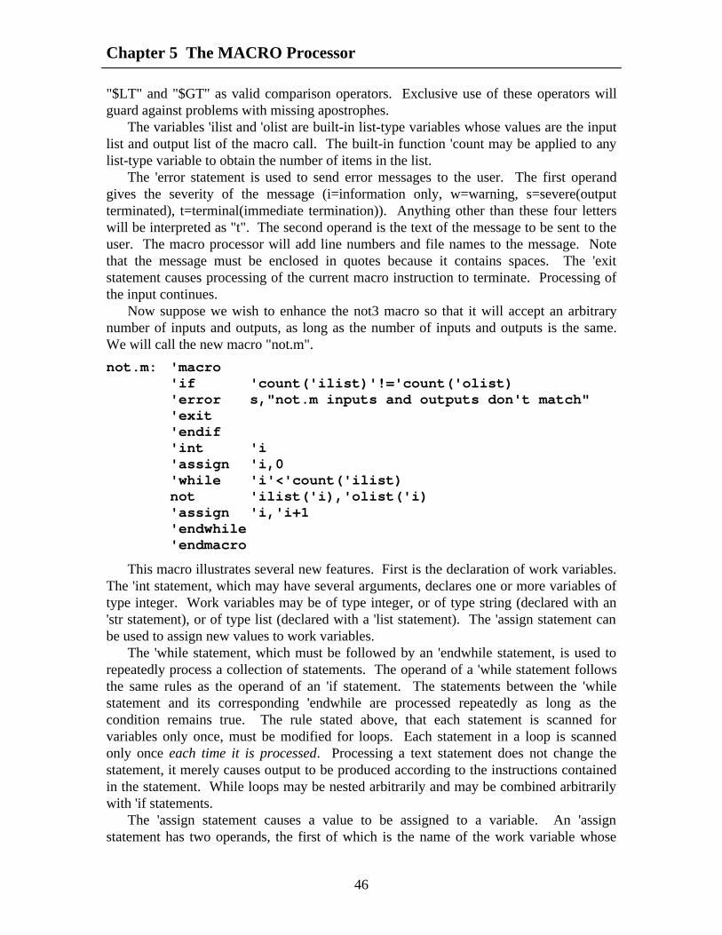
Chapter 5 The MACRO Processor
46
"$LT" and "$GT" as valid comparison operators. Exclusive use of these operators willguard against problems with missing apostrophes.
The variables 'ilist and 'olist are built-in list-type variables whose values are the inputlist and output list of the macro call. The built-in function 'count may be applied to anylist-type variable to obtain the number of items in the list.
The 'error statement is used to send error messages to the user. The first operandgives the severity of the message (i=information only, w=warning, s=severe(outputterminated), t=terminal(immediate termination)). Anything other than these four letterswill be interpreted as "t". The second operand is the text of the message to be sent to theuser. The macro processor will add line numbers and file names to the message. Notethat the message must be enclosed in quotes because it contains spaces. The 'exitstatement causes processing of the current macro instruction to terminate. Processing ofthe input continues.
Now suppose we wish to enhance the not3 macro so that it will accept an arbitrarynumber of inputs and outputs, as long as the number of inputs and outputs is the same.We will call the new macro "not.m".
not.m: 'macro'if 'count('ilist)'!='count('olist)'error s,"not.m inputs and outputs don't match"'exit'endif'int 'i'assign 'i,0'while 'i'<'count('ilist)not 'ilist('i),'olist('i)'assign 'i,'i+1'endwhile'endmacro
This macro illustrates several new features. First is the declaration of work variables.The 'int statement, which may have several arguments, declares one or more variables oftype integer. Work variables may be of type integer, or of type string (declared with an'str statement), or of type list (declared with a 'list statement). The 'assign statement canbe used to assign new values to work variables.
The 'while statement, which must be followed by an 'endwhile statement, is used torepeatedly process a collection of statements. The operand of a 'while statement followsthe same rules as the operand of an 'if statement. The statements between the 'whilestatement and its corresponding 'endwhile are processed repeatedly as long as thecondition remains true. The rule stated above, that each statement is scanned forvariables only once, must be modified for loops. Each statement in a loop is scannedonly once each time it is processed. Processing a text statement does not change thestatement, it merely causes output to be produced according to the instructions containedin the statement. While loops may be nested arbitrarily and may be combined arbitrarilywith 'if statements.
The 'assign statement causes a value to be assigned to a variable. An 'assignstatement has two operands, the first of which is the name of the work variable whose

Chapter 5 The MACRO Processor
47
value will be changed. The second operand is an expression that, when evaluated, willproduce the new value of the variable. The assign operator "<-" may be used instead ofthe 'assign statement. Thus the following two statements are equivalent.
'assign 'i,'i+1'i<-'i+1
An expression may be a constant, such as 0, or the name of a variable such as 'i, or acomplex expression involving constants, variables, operators, and built-in functions. Acomplete list of all operators and built-in functions will be found in the appendices.Among these operators are the arithmetic operators "+", "-", "*", and "/", and thecomparison operators discussed above. The comparison operators return a 1 for true anda 0 for false when used as arithmetic expressions.
The built-in variables 'ilist and 'olist may also be used as built-in functions. Whenthey are used as functions, they take one numeric operand that indicates a position in theinput (or output) list. Positions are numbered from zero. The function returns the text ofthe operand in the specified position in the input (or output) list of the macro call. If theoperand is greater or equal to the number of items in the input (or output) list, the nullstring is returned.
A 'while loop such as that illustrated in the previous example can be expressed moresimply as a 'for loop, as illustrated in the following example.
not.m: 'macro'if 'count('ilist)'!='count('olist)'error s,"not.m inputs and outputs don't match"'exit'endif'int 'i'for 'i<-0,'i'<'count('ilist),'i<-'i+1not 'ilist('i),'olist('i)'endfor'endmacro
The format of a 'for statement is given below.
'for exp1,exp2,exp3<body>'endfor
This statement is functionally equivalent to the following.
exp1'while exp2<body>exp3'endwhile
The first expression initializes loop values, the second is the condition under whichthe loop will continue to iterate, and the third expression is used to update loop variablesfor the next iteration. Any of the three expressions may be parenthesized lists ofexpressions, as the following "two-variable" loop illustrates.

Chapter 5 The MACRO Processor
48
'for ('i<-0,'j<-0), 'i'<'ilim&&'j'<'jlim, ('i<-'i+1,;j<-'j+1)
Loops can be terminated early by use of the 'break and 'continue statements. Neitherof these statements takes any arguments. Executing the 'break statement causes theinnermost loop to be immediately terminated.
Executing the 'continue statement causes the current iteration of the innermost loopto be immediately terminated. If the innermost loop is a 'for loop, the loop variables areupdated. If the continuation condition of the 'for or 'while loop is still true, the nextiteration of the loop begins.
5.4 Accessing The Argument ListThe statement format accepted by the macro preprocessor is more flexible than that
accepted by the FHDL compiler, in that a text statement may have any number ofarguments. In particular, a macro call may have an arbitrary number of arguments. Forexample, let us assume that when the "not.m" macro defined in section 3 is used, theoutputs are all of the form <name>.bar where <name> is the name of the correspondinginput. To save coding time, we could eliminate the need to specify the outputs, since thename of the output can be deduced from the name of the input. Again, to save codingtime, we will allow the user to specify just the input list, without the parentheses. Thusthe user would code the following statement.
not.m a,b,c
This statement would produce the following output.
not a,a.barnot b,b.barnot c,c.bar
The definition of "not.m" would be modified as illustrated below.
not.m: 'macro'int 'i'assign 'i,0'while 'i'<'count('args)not ''i,''i#".bar"'assign 'i,'i+1'endwhile'endmacro
The built-in variable 'args is a list-type variable whose value is the entire argument listof the macro call. The individual arguments are accessed using variables of the form '0,'1, '2, and so forth. The value of the variable '0 is the text of the first argument in theargument list, the value of '1 is the text of the second argument, and so forth. Thevariables '0 and 'ilist are identical, as are '1 and 'olist. Although all argument variables aretechnically of type list, the coercion rules of the preprocessor will cause these variables toassume the type string or the type list, as appropriate to their value and usage.

Chapter 5 The MACRO Processor
49
The operator ' is the indirection operator. When the indirection operator is applied toan expression, the value of the expression is used as a variable name and the value of theindirectly referenced variable is returned. The ' character is prepended to the value of theexpression, so the expression must not include the leading ' character. Although thislooks like multipass substitution, it is not.
Finally, the "#" operator is the concatenation operator. Unlike some macroprocessors, the FHDL macro processor does not provide automatic concatenation ofconsecutive expressions.
5.5 Generating Net NamesIn the examples given so far, all net names were either supplied as operands of the
macro call, or constructed from values supplied by the macro call. In a sense, thesenames are the "primary inputs and outputs" of the macro. If additional net names arerequired beyond those specified as primary inputs and outputs, great care must be taken toavoid duplicating a net name. This is not of concern when one uses an FHDL subnet,because the FHDL circuit flattener renames these nets in such a way as to produce aunique name each time the subnet is called. The macro preprocessor does not providesuch a mechanism, although several different mechanisms can be explicitly programmed.This section will give examples of several different methods for providing unique netnames. Each of these examples will focus on the problem of creating a AOI32 gate out ofAND, OR, and NOT gates. The logic diagram of the AOI32 gate is given below.
I1I2I3
I4I5I6
OUT
The macro to generate gates of this type is given below.
AOI32: 'macro'inputs 'i1,'i2,'i3,'i4,'i5'outputs 'outand ('i1,'i2,'i3),("tempa"#'calln)and ('i4,'i5),("tempb"#'calln)or (tempb#'calln,tempb#'calln),(tempc#'calln)not tempc#'calln,'out'endmacro
The value of the built-in variable 'calln is the number of macro calls that have beenprocessed so far, not counting those that were encountered during the processing of thecurrent macro. The variable 'calln remains constant throughout the processing of thecurrent macro. The value of 'calln is guaranteed to be different for each macro call.

Chapter 5 The MACRO Processor
50
This example also illustrates two different methods for specifying strings. A stringmay be enclosed in quotes thus: "this is a string". If a string is enclosed in quotes it maycontain any character except the null character (zero character). If a string contains onlyupper and lower case letters, digits, periods and underlines, the quotes may be omitted.
The next method of handling internal signals emulates the method used by the FHDLcircuit flattener.
AOI32: 'macro'inputs 'i1,'i2,'i3,'i4,'i5'outputs 'outand ('i1,'i2,'i3),('label#.tempa)and ('i4,'i5),('label#.tempb)or ('label#.tempb,'label#.tempb),('label#.tempc)not 'label#.tempc,'out'endmacro
The the value of the built-in variable 'label is the text of the label field of the macrocall. If there is no label the value of 'label is the null string. This, of course, can causeproblems, so it might be wise to make the following change to the above macro.
AOI32: 'macro'inputs 'i1,'i2,'i3,'i4,'i5'outputs 'out'str 'tlab'if 'label'==""'assign 'tlab,X#'calln'else'assign 'tlab,'label'endifand ('i1,'i2,'i3),('tlab#.tempa)and ('i4,'i5),('tlab#.tempb)or ('tlab#.tempb,'tlab#.tempb),('tlab#.tempc)not 'tlab#.tempc,'out'endmacro
This example illustrates the use of work variables of type string. The next examplemakes use of global variables as well as string variables.

Chapter 5 The MACRO Processor
51
AOI32: 'macro'inputs 'i1,'i2,'i3,'i4,'i5'outputs 'out'str 't1,'t2,'t3'gblint 'label_number'assign 't1,L#'label_number'assign 't2,L#'label_number+1'assign 't3,L#'label_number+2'assign 'label_number,'label_number+3and ('i1,'i2,'i3),('t1)and ('i4,'i5),('t2)or ('t1,'t2),('t3)not 't3,'out'endmacro
This example illustrates the use of global variables. The integer variable'label_number is declared to be global. Global variables retain their values from call tocall, while local variables are initialized at the beginning of each call. Local variables aredeclared using 'int, 'str, and 'list statements, while global variables are declared using'gblint, 'gblstr, and 'gbllist statements. All macros that declare the same global variableshare access to the variable. A macro has no knowledge of undeclared global variables,so it is permissible for one macro to declare a local variable with the same name as aglobal variable declared by another macro. Global integers are initialized to zero, globalstrings are initialized to the null string, and global lists are initialized to the null list.These initializations are also done for local variables at the beginning of each call.
.The second feature illustrated by this example is the coercion between integers andstrings. When an integer variable is used as a string, it is automatically converted to astring of decimal digits without leading zeros (unless the value is zero). Negativenumbers have a leading minus sign. A string that contains only digits can be used as anumber. It will be coerced to an integer before use. The assumed radix is 10, regardlessof leading zeros.
5.6 Function CallsBecause the FHDL macro processor provides variables, if statements and while
statements, it has the full power of a general purpose programming language. Oneimportant feature of general purpose programming languages is the ability to definesubroutines. The ability to nest macro calls is a type of subroutine feature, but there aretimes when the ability to define a function that can be used in an expression is helpful.Any macro may be used as a function by following the macro name with a parenthesizedlist of arguments. The following macro computes the "factorial" function recursively.

Chapter 5 The MACRO Processor
52
factorial: 'macro'if '0'==0||'0'==1'assign 'factorial,1'else'assign 'factorial,'0*factorial('0-1)'endif'endmacro
A macro that is used as a function should not contain text statements. As thisexample illustrates, a macro returns a value by assigning a value to a variable whosename is identical to the macro name. This variable, which is of type string, is a localvariable that is created at the beginning of the function call. If the macro is callednormally, the variable will not exist, therefore it is a good idea to avoid using a macroboth as a function and as an ordinary macro. If, for some reason, you absolutely must dothis, you can use the built-in variable 'callt to determine whether the macro has beencalled as a function or as a normal macro. When used as a string variable, 'callt has thevalue "FUNC" for a function call and the value "STMT" for a normal call. When used asa condition it has the value true for function calls and false for normal calls. When usedin an arithmetic expression, it has the value one for function calls and zero for normalcalls.
In the example above it is not possible to replace the function name "factorial" withan arbitrary expression. However, the "apply" operator, (@) allows you to use anarbitrary expression as a function name. The following is an example of the "apply"operator.
"fact"#"orial"@5
When the apply operator is evaluated, the expression on the left is evaluated andtreated as a function name. The expression on the right is evaluated and treated as theargument list of the function. The value of the expression is the value returned by thefunction.
5.7 Generating Partial FHDL StatementsThe primary method for generating FHDL statements is the text statement. Each text
statement causes a complete FHDL statement to be generated. At times you may wish togenerate only a part of an FHDL statement. To illustrate, let us return to the example ofSection 3. Recall that this example generated a NOT gate for each input/output pair. Letus modify this example to produce a subnetwork rather than generating the not gates "inline." Because a text statement has a fixed number of operands, a single text statementcannot be used to generate the input and output lists. However the 'disp statement can beused to get around this problem, as the following example illustrates.

Chapter 5 The MACRO Processor
53
not.m: 'macro'if 'count('ilist)'!='count('olist)'error s,"not.m inputs and outputs don't match"'exit'endifcircuit'int 'i'disp "\tinputs\t"#'ilist(1)'assign 'i,1'while 'i'<'count('ilist)'disp ","#'ilist('i)'assign 'i,'i+1'endwhile'disp "\n\tinputs\t"#'olist(1)'assign 'i,1'while 'i'<'count('olist)'disp ","#'ilist('i)'assign 'i,'i+1'endwhile'disp "\n"'assign 'i,0'while 'i'<'count('ilist)not 'ilist('i),'olist('i)'assign 'i,'i+1'endwhileendcircuit'endmacro
The 'disp statement is used to generate unformatted text. The statement has oneoperand, which is evaluated and placed in the output. Note that opcodes, separators andstatement terminators must be explicitly specified. This example also illustrates the useof special characters in character strings. In general, anything that is acceptable in the Clanguage is acceptable to the macro preprocessor, except the null character (\0). The 'dispstatement can be used to create non-FHDL output.
5.8 The else-if ConstructThere are times when one must create a multi-way conditional depending on several
different conditions. One way to do this is to use nested 'if statements, that is, place asecond 'if statement in the 'else part of the first statement. This relatively commonconstruct can be expressed more compactly using the 'elif statement. For example,suppose you want to generate three different types of statement, depending on whetherthe variable 'x has the value 1, 2 or 3. The following sequence of statements willaccomplish this.

Chapter 5 The MACRO Processor
54
'if 'x'==1and (a,b),c'elif 'x'==2or (a,b),c'elif 'x=3xor (a,b),c'else'error s,"Invalid value of x"'endif
Note that a single 'endif statement is used to terminate the 'if construct. The 'elseportion of the statement will be executed if none of the preceding conditions are true.The body of an 'elif portion will be executed if the corresponding condition is true and allpreceding conditions are false. The 'elif statement has a single operand which follows thesame rules as the operand of the 'if statement.
5.9 Accessing AttributesIn addition to ordinary operands, many FHDL statements have attributes which are of
the form <name>=<value> or <name>=(<value1>, ... ). These types of operands are alsoacceptable to the macro processor. When an attribute is used on a macro call, both thename of the attribute and the value may be specified as expressions. In the macrodefinition, the name and the value of the attribute may be accessed separately using the'aname and 'avalue built-in functions. Suppose the following macro call has been used.
stmt5: newmac (a,b,c),(d,e,f),type=large
Within the definition of "newmac" the expression 'aname('2) will return the value"type" and the expression 'avalue('2) will return the value "large". The expression'aname('1) will return the null string, and the expression 'avalue('1) will return the list(d,e,f). In general if the operand of 'aname is not of the form <name>=<value> then'aname will return the null string. If the operand of 'avalue is not of the form<name>=<value> then 'avalue will return the operand itself.
The 'aname and 'avalue functions may also be used to extract the components ofexpressions of the form <value>-><field-name>, which are used by the ROM and PLApreprocessors. For expressions of this form, 'aname returns the field name while 'avaluereturns the value.
5.10 Arithmetic and Logical Expressions.As mentioned above, arithmetic expressions may contain the operators +, -, *, and /.
In addition unary plus and minus are allowed. Note that the division operator is integerdivision. The operator "%" can be used to obtain remainders. Thus 5%2 would give thevalue 1. Exponentiation can be performed by using the exponentiation operator, **.
The comparison operators '<, '>, '<=, '>=, '==, and '!= can be used in arithmeticexpressions. These operators return 0 for a false condition and 1 for a true. The operators&&, || and ! may also be used in arithmetic expressions. The binary operator && givesthe value 0 if either of its operands is zero, and the value 1 otherwise. The binary

Chapter 5 The MACRO Processor
55
operator || gives the value 0 if both of its operands are zero, and the value 1 otherwise.The unary operator ! gives the value 1 if its operand is zero and the value 0 otherwise.
All numbers and integer variables are represented as 32-bit binary numbers. Thereare a number of bit-level operations that can be performed on numbers and integervariables. The operator "&" returns the bitwise AND of its two operands, while theoperator "|" returns the bitwise OR. The unary operator "~" returns the bitwisecomplement (ones complement) of its operand. The binary operator "^" returns thebitwise EXCLUSIVE OR of its operands. The binary operators ">>" and "<<" performright and left shifts respectively. The left-hand operator is shifted the number of bitsspecified by the right-hand operator. Examples are 'x>>2 and 'y<<3. Either operand maybe an expression.
The normal operator precedence for arithmetic operators is given below in low to highorder. Operators listed on the same line are of equal precedence. Normal precedence canbe overridden with parenthesis.
||, |, ^&&, &!, ~'<, '>, '==, '<=, '>=, '!=<<, >>+, -*, /, %**unary +, unary -
The evaluation of expressions containing the operators +, -, *, /, &, |, and ! maysometimes give unexpected results. Because these operators are also used by other FHDLparsers, the macro preprocessor makes an effort not to evaluate these operators. Placingan apostrophe ahead of one of these operators will force its evaluation by the macroprocessor. To prevent the evaluation of an operator, enclose the entire expression inquotation marks.
5.11 String Handling Functions.The macro processor provides several string handling functions. The concatenation
operator (#) mentioned above can be used to concatenate strings. In addition, the 'substrfunction can be used to extract substrings of a given string. The 'substr function requiresthree operands. The first is the string from which the substring is to be extracted. Thesecond operand is the starting position of the substring. The first character of the string isin position zero. The third operand is the length of the substring. If the length isspecified as zero, the substring from the starting position to the end of the subject string isreturned. Some examples of this function are given in the following table.
'substr("abcdef",0,3) returns "abc"
'substr("abcdef",3,1) returns "d"

Chapter 5 The MACRO Processor
56
'substr("abcdef",2,3) returns "cde"
'substr("abcdef",2,0) returns "cdef"
A negative starting position is treated as zero. A starting position greater than orequal to the length of the string causes the null string to be returned. A negative length istreated as a zero. If there are not enough characters in the string to create a substring ofthe specified length, the substring from the starting position to the end of the string isreturned. If the 'substr function is specified with fewer than three arguments, the omittedarguments are treated as zeros. Any of the three arguments may be expressions.
The 'len function can be used to count the characters in a string. The 'len functionrequires one argument which should be a string. It returns the number of characters in astring. The following macro fragment can be used to process the characters of a stringone at a time.
'int 'i'str 'char'assign 'i,0'while 'i'<'len('0)'assign 'char,'substr('0,'i,1)/*... process 'char ...*/'assign 'i,'i+1'endwhile
The macro preprocessor provides several "read only" built-in string variables. Thevariable 'null can be used in place of "" to represent the null string. The variables 'calltand 'label have already been discussed. In addition, the variable 'opcode contains theopcode of the macro call. (As will be explained below, a macro can be given more thanone name, so this variable does have some use.) The value of the variable 'run can beset from the UNIX command line. Its default value is "alogic".
5.12 List Handling FeaturesThe macro preprocessor provides features for declaring and processing lists. A list
variable is declared as in the following example.
'list 'listvar
The 'gbllist statement can be used to declare global list variables. The built-in listvariables 'ilist, 'olist and 'args have already been discussed. A list constant is simply a listof elements separated by commas and enclosed in parentheses. Thus to assign a three-element list to the variable declared above, use the following statement.
'assign 'listvar,(a,bbb,qed)
The first element of a list can be accessed using the 'first function, so the function call'first((a,b,c)) returns the string "a". The 'rest function can be used to remove the firstelement of the list and return the rest. Thus 'rest((a,b,c)) returns the list (a,b), and'rest((a,b)) returns the string "b". If the list contains only one element, 'rest will return the

Chapter 5 The MACRO Processor
57
null string. The 'select function can be used to select a particular element of a list. Thisfunction requires two arguments, a list and a number indicating which element to select.Elements are numbered starting with zero, so 'select((a,b,c),0) returns "a" while'select((a,b,c),2) returns "c". If the second argument is greater or equal to the number ofelements in the list, the null string is returned.
Lists may be nested, so the following is a valid example of a list constant.
(a,b,(c,(d,dd),e),f)
Because of list nesting, the functions 'first, 'rest and 'select may return either a list or astring. To determine whether the object returned by one of these functions is a string or alist, use the 'atom function. The function 'atom('first((a,b,c))) will return true, while'atom('rest((a,b,c))) will return false. As for other conditionals, if these true and falsevalues are used in arithmetic expressions they are treated as one and zero respectively.You can test for the null string (or null list, which is the same thing) by using the function'nil. The function 'nil returns true if its argument is the null string (or null list) and falseotherwise.
Lists can be constructed one element at a time by using the functions 'cons and 'consr.These functions take two arguments, the second of which must be a list, and the first ofwhich must be an element to be added to the list. If the second argument is not a list, it iscoerced to a single-element list. The first argument may be an integer, a string, or anotherlist. The function 'cons adds the element to the beginning of the list, while the function'consr adds the element to the end of the list.
When a list is used as a string it is coerced to a string. If it is a single-element list, theresult is the value of the single element. If it is a multi-element list, the result is a stringthat begins with "(" and ends with ")" and contains the values of the elements separatedby commas. Thus the list (a,b,c) is coerced to the string "(a,b,c)". When a list is used asan integer, it is first coerced to a string then the string is coerced to an integer. When aninteger or a string is used as a list, it is coerced to a single-element list.
5.13 Type Conversion FunctionsThe macro preprocessor provides automatic type conversion between lists, strings,
and integers. To summarize, numeric strings are converted to integers using a standard(character) decimal-to-binary conversion. Non-numeric strings are converted to zeros.Integers are converted to strings by using a standard binary-to-decimal conversion thatproduces no leading zeros. Conversions between lists and the other two types are detailedin Section 12.
Automatic type conversions are supplemented by several functions that do explicittype conversions. Integers can be converted to fixed-length strings using the 'itosfunction. The 'itos function requires two arguments, the first of which is the integer to beconverted, and the second of which is the width of the number to be produced. If theconverted string is shorter than the specified width, it is padded on the left with zeros. Ifit is longer than the specified width, characters on the left are truncated.
In addition to the decimal conversions, the functions 'xtoi, 'otoi, 'btoi, 'hex, 'octal, and'binary can be used to do conversions using the bases 16, 8, and 2. The function 'xtoiconverts a string containing digits and the letters a-f (or A-F) into an integer. The

Chapter 5 The MACRO Processor
58
characters are assumed to represent base-16 digits. Similarly the functions 'otoi and 'btoican be used to convert strings containing the characters 0-7 (for 'otoi) or 0-1 (for 'btoi)into integers. The characters of the string are assumed to be octal (for 'otoi) or binary (for'btoi) digits. The functions 'hex, 'octal, and 'binary perform integer to string conversions.The function 'hex produces a base-16 number using the additional digits a-f, while 'octaland 'binary produce base-8 and base-2 numbers respectively.
Integer constants may be specified in decimal, octal, or hexadecimal. Decimalnumbers other than zero begin with a non-zero digit and contain only the digits 0-9.Octal numbers begin with a zero and contain only the digits 0-7. Hexadecimal numbersbegin with the two characters "0x" or "0X" and thereafter contain only the characters 0-9,a-f, and A-F. Note that the operand of 'xtoi must not contain the leading "0x" or "0X"characters. Furthermore, the operand of 'otoi need not start with a zero. Furthermore, thefunction 'hex will not prepend "0x" or "0X" to its output, nor will the output of 'octalnecessarily start with a zero.
If the functions 'hex, 'octal, and 'binary are supplied with a single operand, the resultstring will begin with a non-zero digit, and will be just long enough to contain allsignificant digits of the converted value. If a second operand is supplied, it must be aninteger specifying the number of digits to be produced. The result string will be paddedwith zeros or truncated on the left to produce a string of the specified length.
The function 'ctoi can be used to convert a character to an integer whose value is thebinary value of the character in the underlying character representation. This is ascii formost systems, so 'ctoi(" ") usually returns the number 32. The operand of 'ctoi is a string.All characters but the first are ignored.
5.14 Redirecting OutputGenerating logic all inline is the natural mode of operation for the macro processor.
At times it may be desirable to generate a subnetwork and place references to it inline.This complicates the data generation problem, because the subnetwork and the referencemust be generated at different places in the code, and will be separated by anunpredictable number of statements.
The output redirection facility of the macro processor was designed to solve thisproblem. The output of the macro processor is divided into three sections, the standardoutput or inline section, the network section, and the subnetwork section. For theexamples given above, only the inline section is used. When output is generated theinline section appears first, the network section second, and the subnetwork section third.Output may be added to these sections in arbitrary order. For example consider thefollowing macro definition of a full adder.

Chapter 5 The MACRO Processor
59
fulladd: 'macro'inputs 'a,'b,'c'outputs 'sum,'carry'gblint 'fa_done'if 'fa_done'==0'subnetwk
fa: circuitinputs a,b,coutputs sum,carryxor (a,b),i1xor (i1,c),sumand (a,b),i2and (a,c),i3and (b,c),i4or (i1,i2,i3),carryendcircuit'assign 'fa_done,1'endif'stdout
'label: fa ('a,'b,'c),('sum,'carry)'endmacro
The statement 'subnetwk changes the current output section to be the subnetworksection. The statement 'stdout changes the current output section to the inline section.The 'network statement changes the current output section to the network section. In thisexample, the definition of the circuit "fa" will appear after the all calls to "fa".
The output redirection feature also allows several circuits to be constructedsimultaneously in piecemeal fashion. This is done by creating named subnetwork andnetwork sections. The following example demonstrates the use of named subnetworksections.
'exam: 'macro'subnetwk a
a: circuit'subnetwk b
b: circuit'subnetwk ainput aaoutput aaanot aa,aaaendcircuit'subnetwk binput bboutput bbbnot bb,bbbendcircuit'stdout'endmacro

Chapter 5 The MACRO Processor
60
In this example, two named subnetwork sections, a, and b are defined. Namedsubnetwork sections appear in the order defined in the subnetwork section of the output.If the unnamed subnetwork section is used in conjunction with named subnetworksections, it is treated as a named subnetwork section whose name is the null string. Thefirst 'subnetwk statement encountered that contains a particular name defines a namedsubnetwork section. All other subnetwork sections containing the same name add to thenamed subnetwork section. The name may be a complex expression. Named networksections are handled similarly.
5.15 Creating Macro LibrariesMacros may appear inline with the text of a circuit, or they may be placed in macro
libraries, and accessed automatically. A macro library is a directory whose files containmacro definitions. Each macro must be a separate file, and the file name must exactlymatch the name of the macro. A macro may be given more than one name by using theUNIX "ln" command to link macro names.
A macro library is often used to define a coordinated set of macros for a particularapplication. When this is done, it is sometimes necessary to have special initializationand termination macros. One way to use such macros is to force all users to place theinitialization and termination macros at appropriate points in the text of their circuits.Another way is to explicitly define initialization and termination macros in the library.The initialization macro must be named "$START" and the termination macro must benamed "$END". If an initialization macro is defined, it will be invoked before the firststatement of the user's circuit is interpreted. If a termination macro is defined it will beinvoked after the last statement of the user's circuit is interpreted.
Several macro libraries may be used in a single run. It is permissible for the samemacro-name to appear in several libraries. In this case the form of the UNIX commandthat invokes the preprocessor determines which library to use for a particular macro. Seesection 18 for details.
5.16 Including TextIt may be necessary to define a large number of global variables, that are shared by a
number of macro definitions. It may also be necessary to replicate other text in eachmacro. Explicit replication of text in each macro makes that body of text next toimpossible to change. The include feature of the macro processor can be used tocircumvent this problem. The following example illustrates the use of this feature.
exam: 'macro'include global_defs...'endmacro
This include statement causes the file "global_defs" from the macro library to beincluded in the text of the macro "exam". The file name may not be an expression. Itmust be a string either with or without quotes. If the name is not found in any macrolibrary, it will be treated as an ordinary file name. If the file can be found using the

Chapter 5 The MACRO Processor
61
ordinary rules for locating files, (i.e. full path name, relative to current directory) that filewill be included in the text, otherwise a "nonexistent file" message will be issued.
The 'include statement may be nested arbitrarily, but beware of circular references.Circular references always cause a non-terminating expansion of the text. This is becausethe 'include statement is executed as the text is read from the source files, not when thecode is interpreted. Every 'include statement is executed unconditionally regardless ofwhere in appears in the text. Thus the following example will cause two includestatements to be executed.
exam: 'macro'if 'run'=='abc''include abc'else'include xyz'endif'endmacro
For convenience, all include files may be gathered into an include directory whichwill be treated as a macro library by the preprocessor. It is important that the names ofinclude files and macros be distinct. See section 18 for more information.
5.17 A Word on Format.All portions of a statement may be specified as expressions. The examples given in
preceding sections show, for the most part, constants in the label field and opcode field.In fact, both of these fields may be specified as complex expressions. Preprocessorstatements, however, can be specified only with constant opcodes. An expression cannotbe used to generate a preprocessor keyword.
Statements may be assigned more than one label, as illustrated in the followingexamples.
a:b:c: 'macro
a:;b:;c: 'macro
When more than one label is used on a macro call, the 'label variable contains thevalue of the first label. The built-in list variable 'llist can be used to access the entire listof variables attached to the macro call. Also, the built-in function of the same name canbe used to access various portions of the label list.
Macros may be assigned more than one name by placing several labels on the 'macrostatement, or by placing additional names in the operand field of the 'macro statement. (Ifonly one name is used, it may appear either in the label field or in the operand field.)When a macro is given more than one name, any of the assigned names may be used as anopcode to invoke the macro. The actual name used can be determined in the macrodefinition by using the 'opcode variable. If "function call" macros are given more thanone name, the 'opcode variable must be used to return the function value. This is becausethe name of the "return" variable always matches the name used to invoke the function. If

Chapter 5 The MACRO Processor
62
one of the macro's other names is used, an "undefined variable" message will be issued.The precise method for doing this is explained below.
The six statements used to define variables may have label fields. If labels are usedon these statements, the labels are taken to be the names of additional variables to bedefined. Thus the following statement defines six integer variables.
a:b:c: 'int d,e,f
When a label of a 'macro statement or one of the six variable-defining statementscontains commas, the label is treated as a list of names. Thus the following statementassigns three names to a macro.
x,y,z: 'macro
And the following statement defines three integer variables.
a,b: 'int c
The previous examples also illustrate another syntactic principle of the macroprocessor. The expression 'x means "the value of x". The expression x means "thevariable x". Although it is less confusing to use the form 'x everywhere, it is notsyntactically correct to do so. HOWEVER, the macro processor permits the syntacticallyincorrect form to be used in variable definitions and in assignments. The syntacticallycorrect way to increment the value of the variable 'i is as follows.
'assign i,'i+1
However, the preprocessor accepts the following statement as incrementing the valueof 'i.
'assign 'i,'i+1
The syntactically correct meaning of this statement is "obtain the value of i and usethe value as the name of the variable to be assigned." Since indirect assignment tends tobe quite rare, this is taken to be a miswritten direct assignment. It is actually goodpractice to use the syntactically incorrect forms, since this will tend to lessen thefrequency with which you forget to use the leading ' mark. When it is necessary to do anindirect assignment this can be done by enclosing the name of the variable in parenthesesas the following statement illustrates.
'assign ('indvar),'i+1
Anything other than a user defined variable as the first operand of an 'assignstatement will cause the syntactically correct rules to be applied. Thus, returning a valuefrom a function-call macro with more than one name can be done using a statementsimilar to the following.
'assign 'opcode,"return value"
In the examples given above, the error message on the 'error statement was specifiedas a single string. In fact an arbitrary expression may be used, as illustrated below.

Chapter 5 The MACRO Processor
63
'error s,"input count="#'count('ilist)#" should be 3"
The severity code may also be supplied as a complex expression. Only the firstcharacter of the operand is significant. Therefore a severity code of "severe" or"superfluous" is the same as "s".
Comments may be included in macros. There are two types of comment statements.If the opcode "comment" is used (without the leading ' mark) the comments will beincluded in the generated text. If the opcode 'comment is used, the comments will notappear in the generated text. The first type of comments are used to includeinformational messages in the generated text. The second type are used to comment themacro itself. In either case the body of the comment may contain any printable character.A semicolon or a newline character marks the end of a comment.
Within a macro the order of variable definition statements is irrelevant. The first useof a variable may precede its definition. Similarly the first use of a macro may precedethe definition of the macro. It is necessary, however, for all macro definitions to precedeall non-macro text in an input file. The non-macro text in an input file is treated as anunnamed macro, so preprocessor statements may appear in the non-macro text. Inparticular 'include statements may appear in non-macro text.
5.18 Executing the PreprocessorThe preprocessor is executed using the "alogic" command. The simplest form of this
command is to use it as a filter for FHDL input, as the following illustrates. (The alogiccommand is executed automatically if the fhdl command with the "-n" option is used.)
alogic input.ckt | fhdl >input.c
A macro library can also be used with this form as the following command illustrates.
alogic -m maclib input.ckt | fhdl >input.c
The name of the macro library is "maclib". File names for both macro libraries andinput files follow the usual UNIX rules for file name formation. The flag "-m" mustprecede the name of each macro library. The "-m" flag must be separated from the macrolibrary name by one or more spaces or tabs. If more than one macro library is specified,and the same macro is defined in more than one library, the definition encountered lasttakes precedence. This is also true for the initialization and termination macros. Only thelast encountered initialization and termination macros will be executed. The following isa command that specifies two macro libraries "mac1" and "mac2" and an includedirectory "include1".
alogic -m mac1 -m mac2 -m include1 input.ckt | fhdl >input.c
In most cases, complex applications such as this will have shell files that supply thelibrary names. File names without the preceding "-m" flag are input files. There may beseveral input files specified as in the following example.
alogic -m mac1 input1.ckt input2.ckt input3.ckt | fhdl >input.c
Input files are processed one at a time in the order specified. After the processing of afile is complete, the macros defined in the file are retained and made available to allsucceeding files. This may cause problems if several files define the same macro (in this

Chapter 5 The MACRO Processor
64
case, break into several runs). The main use of this feature is to allow all non-librarymacros to be placed in a header file that precedes the circuit file on the command line.
A file name of "-" (a single dash preceded and followed by one or more spaces ortabs) indicates the standard input. The standard input is read (possibly several times)whenever the file "-" is processed.
The value of the variable 'run may be set using the "-r" flag on the command line.The "-r" flag must be preceded and followed by one or more spaces or tabs. The(command line) argument following the "-r" flag is assigned to the 'run variable. Theremust be only one "-r" flag on the command line. All input files in a particular run sharethe same value of the 'run variable. The following is an example of setting the 'runvariable.
alogic -m mlib -r old input.ckt | fhdl >input.c
Normally the output of the macro preprocessor is directed to "stdout". (Errormessages are directed to "stderr".) This output can be redirected in the usual fashion, or itcan be explicitly directed to an output file by using the "-o" flag on the command line.The "-o" flag must be preceded and followed by one or more spaces or tabs. The outputof the preprocessor will be placed in the file name following the "-o" flag. There may beat most one "-o" flag on the command line. If several output files are needed, break intoseveral runs.

Chapter 5 The MACRO Processor
65
5.19 Macro Statement Summary
5.19.1 Operand-Type Designators
Designator Meaning- none allowedA ArbitraryE ExpressionF File NameL i,w,s, or tV Variable Name
VL A list of variable names separated by commasX an expression or omitted
5.19.2 Statements
Opcode Operands Function'assign V,E Evaluate E and assign to V'break - Terminate innermost loopcomment A Pass comment through to output'comment A Comment disappears from output'continue - Terminate the current iteration of the innermost loop'disp E Output a portion of an FHDL statement'elif E Introduce an alternative condition into an IF statement'else - Introduce the ELSE portion of an IF statement'endfor - End of a 'for loop'endif - End of an IF statement'endmacro - End of a macro definition'endwhile - End of a 'while loop'error L,E Print an error message E of severity L'eval E Evaluate the expression E'exit - Terminate evaluation of the current macro<expression> - Evaluate the expression'for E,E,E Begin a for loop. Operands are init, cond, incr'gblint VL Define global integer variables'gbllist VL Define global list variables'gblstr VL Define global string variables'if E Begin an if statement with condition E'include F Include the file named F in the current macro or input file'input VL Define input-signal operand names'int VL Define local integer variables'list VL Define local list variables

Chapter 5 The MACRO Processor
66
Opcode Operands Function'macro VL Begin a macro definition'network X Begin or resume a (possibly named) network section'output VL Define output-signal operand names'stdout X Begin or resume a (possibly named) standard-output section'str VL Define local string variables'subnetwk X Begin or resume a (possibly named) subnetwork section'while E Begin a while loop with continuation condition E

Chapter 5 The MACRO Processor
67
5.20 Macro Function and Builtin VariableSummary
5.20.1 Operand-Type Designators
Designator Meaning- none, this is a variableA Macro Argument, or a part thereofN Numeric ExpressionL List ExpressionS String ExpressionC Single-Character String ExpressionE Arbitrary Expression
5.20.2 Functions and Variables
Opcode Operands Function'aname A Returns the name for expressions of the form <name>=<value> or
<value>-><name>.'args - Returns a list containing all macro arguments for the current call.'args N Returns the Nth argument of the current macro call.'atom E Returns 0 if E is a list, 1 otherwise.'avalue A Returns the value for expressions of the form <name>=<value> or
<value>-><name>.'binary N Converts N to a binary string and returns the result.'binary N,N Converts arg1 to a fixed-length binary string (arg2) and returns
the result.'btoi S Treats S as a string of binary digits, and converts it to an integer.'calln - The sequential number of the macro call that invoked the current
macro.'callt - Type of current macro call. True for functions, false for
statements. Strings "STMT" or "FUNC" if evaluated as a string.'cons E,L Append E to the head of the list L, and return the result.'consr E,L Append E to the tail of the list L, and return the result.'count L Count the elements of list L and return the result.'ctoi C Return the integer value in the underlying character set of the
character C.'first L Return the first element of list L.'hex N Convert the number N to a string of hexadecimal digits.'hex N,N Convert the first argument to a fixed-length string of hexadecimal
digits, length equal to second argument.'ilist - For FHDL gate-type macro calls, return the list of input names.

Chapter 5 The MACRO Processor
68
Opcode Operands Function'ilist N For FHDL gate-type macro calls, return the Nth input name.'itos N,N Convert the first argument to a string of decimal digits whose
length is equal to the second argument. (Automatic coerciontakes care of variable-length strings.).
'label - The label of the current macro call.'len S Returns the length of the string argument.'llist - Returns the list of labels for the current macro call.'llist N Returns the Nth label of the current macro call.'nil L Returns 1 if the argument is the null list, 0 otherwise.'null - The null string or the null list.'octal N Converts N to a string of octal digits.'octal N,N Converts the first argument to a fixed-length string of octal digits.
The length is equal to the second argument.'olist - For FHDL gate-type macro calls, return the list of output names.'olist N For FHDL gate-type macro calls, return the Nth output name'opcode - The opcode of the current macro call.'otoi S Treats S as a string of octal digits and returns the integer value.'rest L Deletes the first element from a list and returns the rest. For
single element lists, returns 'null.'run - The value of the -r option from the alogic command line. "alogic"
is default.'select L,N Select the Nth element from list L.'substr S,N,N Return the substring of S that starts at the character denoted by the
first argument (0 is the first char of S) and spans a number ofcharacters equal to the second argument.
'substr S,N Return the substring of S that starts at the character denoted by thefirst argument (0 is the first char of S) and extends through theend of the string.
'xtoi S Treat S as a string of hexadecimal digits, and return the integerequivalent.
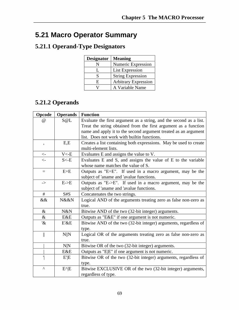
Chapter 5 The MACRO Processor
69
5.21 Macro Operator Summary
5.21.1 Operand-Type Designators
Designator MeaningN Numeric ExpressionL List ExpressionS String ExpressionE Arbitrary ExpressionV A Variable Name
5.21.2 Operands
Opcode Operands Function@ S@L Evaluate the first argument as a string, and the second as a list.
Treat the string obtained from the first argument as a functionname and apply it to the second argument treated as an argumentlist. Does not work with builtin functions.
, E,E Creates a list containing both expressions. May be used to createmulti-element lists.
<- V<-E Evaluates E and assigns the value to V.<- S<-E Evaluates E and S, and assigns the value of E to the variable
whose name matches the value of S.= E=E Outputs as "E=E". If used in a macro argument, may be the
subject of 'aname and 'avalue functions.-> E->E Outputs as "E->E". If used in a macro argument, may be the
subject of 'aname and 'avalue functions.# S#S Concatenates the two strings.
&& N&&N Logical AND of the arguments treating zero as false non-zero astrue.
& N&N Bitwise AND of the two (32-bit integer) arguments.& E&E Outputs as "E&E" if one argument is not numeric.'& E'&E Bitwise AND of the two (32-bit integer) arguments, regardless of
type.|| N||N Logical OR of the arguments treating zero as false non-zero as
true.| N|N Bitwise OR of the two (32-bit integer) arguments.| E&E Outputs as "E|E" if one argument is not numeric.'| E'|E Bitwise OR of the two (32-bit integer) arguments, regardless of
type.^ E^|E Bitwise EXCLUSIVE OR of the two (32-bit integer) arguments,
regardless of type.
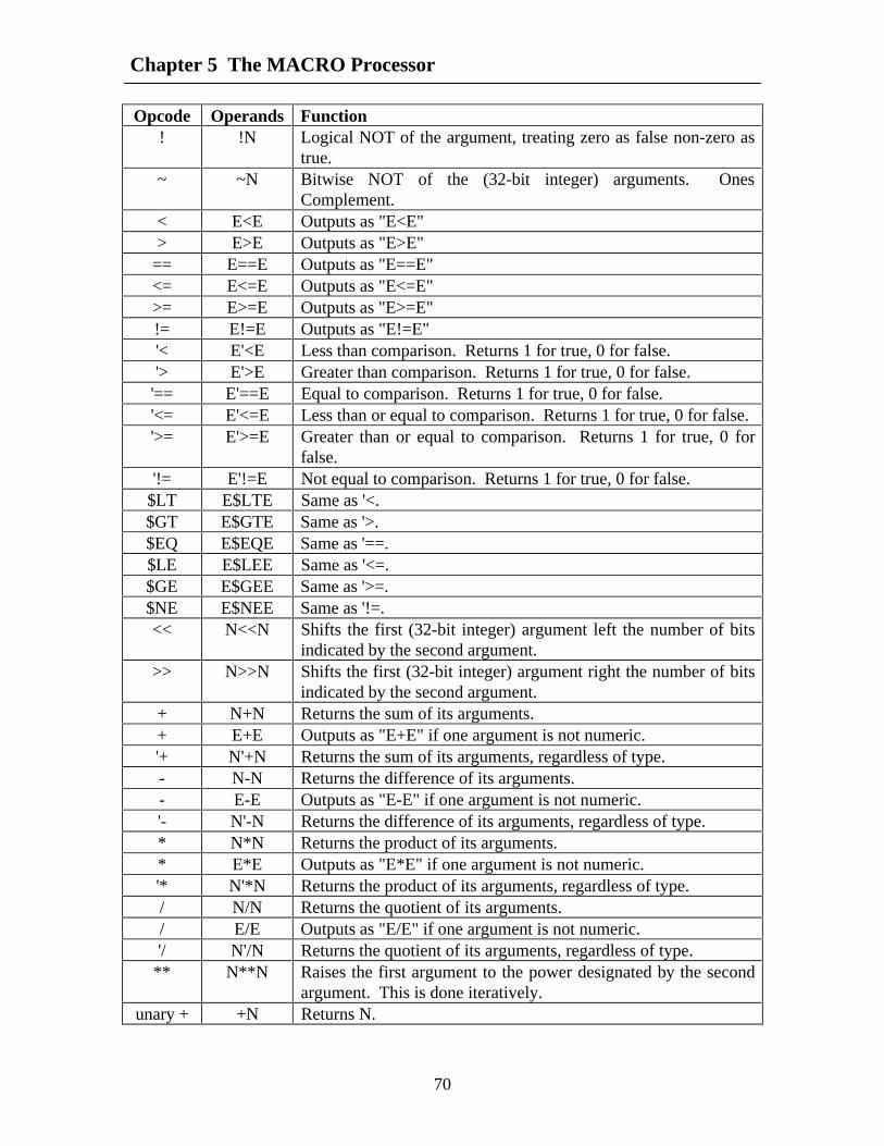
Chapter 5 The MACRO Processor
70
Opcode Operands Function! !N Logical NOT of the argument, treating zero as false non-zero as
true.~ ~N Bitwise NOT of the (32-bit integer) arguments. Ones
Complement.< E<E Outputs as "E<E"> E>E Outputs as "E>E"
== E==E Outputs as "E==E"<= E<=E Outputs as "E<=E">= E>=E Outputs as "E>=E"!= E!=E Outputs as "E!=E"'< E'<E Less than comparison. Returns 1 for true, 0 for false.'> E'>E Greater than comparison. Returns 1 for true, 0 for false.
'== E'==E Equal to comparison. Returns 1 for true, 0 for false.'<= E'<=E Less than or equal to comparison. Returns 1 for true, 0 for false.'>= E'>=E Greater than or equal to comparison. Returns 1 for true, 0 for
false.'!= E'!=E Not equal to comparison. Returns 1 for true, 0 for false.
$LT E$LTE Same as '<.$GT E$GTE Same as '>.$EQ E$EQE Same as '==.$LE E$LEE Same as '<=.$GE E$GEE Same as '>=.$NE E$NEE Same as '!=.<< N<<N Shifts the first (32-bit integer) argument left the number of bits
indicated by the second argument.>> N>>N Shifts the first (32-bit integer) argument right the number of bits
indicated by the second argument.+ N+N Returns the sum of its arguments.+ E+E Outputs as "E+E" if one argument is not numeric.'+ N'+N Returns the sum of its arguments, regardless of type.- N-N Returns the difference of its arguments.- E-E Outputs as "E-E" if one argument is not numeric.'- N'-N Returns the difference of its arguments, regardless of type.* N*N Returns the product of its arguments.* E*E Outputs as "E*E" if one argument is not numeric.'* N'*N Returns the product of its arguments, regardless of type./ N/N Returns the quotient of its arguments./ E/E Outputs as "E/E" if one argument is not numeric.'/ N'/N Returns the quotient of its arguments, regardless of type.** N**N Raises the first argument to the power designated by the second
argument. This is done iteratively.unary + +N Returns N.

Chapter 5 The MACRO Processor
71
Opcode Operands Functionunary + +E Outputs as "+E" if the argument is not numeric.unary '+ '+E Returns E regardless of type.unary - -N Returns the negation of N. Two's Complement.unary - -E Outputs as "-E" if the argument is not numeric.unary '- '-E Returns the negation of E regardless of type.
' 'E Evaluates its argument, and treats the result as a variable name,and then returns the value of the named variable. If theexpression is numeric and evaluates to n, the value of the nthargument of the current macro call is returned.

Chapter 5 The MACRO Processor
72
5.22 Macro Processor Keywords'aname'args'assign'atom'avalue'binary'break'btoi'calln'calltcomment'comment'cons'consr'continue'count'ctoi'disp'elif'else'endfor'endif'endmacro'endwhile'error'eval'exit'first'for'gblint'gbllist'gblstr
'hex'if'ilist'include'input'int'itos'label'len'list'llist'macro'network'nil'null'octal'olist'opcode'options (reserved for future use)'otoi'output'rest'run'select'stdout'str'subnetwk'substr'while'xtoi

Chapter 5 The MACRO Processor
73
5.23 Macro Operator PrecedenceAll preprocessor operators are listed from lowest priority to highest. If more than one
operator is listed on a line, all operators on the same line have equal priority. The firstcolumn indicates the associativity of the operator.
Precedence Associativity OperatorLow Right @
Right , (Yes, comma is treated as an operator)Right <-Left = ->Left #Left || | ^ '|Left && & '&Right ! ~Non assoc. < > == <= >= !=Non assoc. '< '> '== '<= '>= '!= $LT $GT $EQ $LE $GE $NENon assoc. << >>Left + - '+ '-Left * / % '* '/Right **Right unary + unary - unary '+ unary '-
High Right ' (indirection)

75
CHAPTER 6
The Test Driver Language
The FHDL Test Driver Language is designed to simplify the process of creating andrunning functional tests. It is capable of running tests, suppressing all but the"interesting" results, checking for errors, generating the same vector repeatedly until acondition becomes true, and generating error messages. Driver-language statementsinteract dynamically with the simulation to produce results that cannot be achieved in astatic vector environment.
6.1 IntroductionThe FHDL Test-Driver Language is intended to simplify the testing of circuits
specified using the Florida Hardware Design Language. The features described in thischapter are automatically provided when the fhdl command with the "-n" option is used.These features are not available otherwise. The Driver language can be used to specifythe format of tests, and the manner in which tests are applied to the circuit. Feedbackfrom the circuit under test can be used to control the testing process. Figure 1 illustratesthe relationship between the driver created using the FHDL driver language, and thecircuit under test.

Chapter 6 The Test Driver Language
76
DiskFiles
DDRRIIVVEERR
CCooddee
Figure 1. The Relationship of the Driver and the CUT.
The Driver can be used to save time in generating test vectors, and can be used tocompare expected results with the real results and report discrepancies.
6.2 The Format of the LanguageThe format of driver language statements is given below. The format is similar to that
of the other FHDL languages.
<label>: <opcode> <operands>
Each statement contains a label field, and op-code field and an operands field. Thelabel field begins at the first character of a statement and ends with a colon. A label maycontain any combination of letters, digits, underlines and periods. The label field isseparated from the op-code field by one or more spaces or tabs. If the label is omitted,the colon must also be omitted and the statement must begin with a space or a tab tosignify that the label is omitted. Labels are ignored on most driver language statements.The opcode field must be separated from the operands field by one or more spaces ortabs. The operands field is optional for some statements, but the op-code is required forall statements. A statement is terminated by a carriage return or a semicolon. If a lineends in a comma, the statement is assumed to be continued on the next line.
The driver provides local variables and allows the nets of the Circuit Under Test(CUT) to be accessed directly. Variable names and net names consist of an arbitrarystring of letters, digits, underlines and periods. Case is significant for variable names andnet names so Abc, ABc, and abC are three different variable or net names. Case is notsignificant for driver-language keywords, so the keywords Driver, DRIVER, and DrIvErare all the same.
A set of driver specifications must begin with a "driver" statement and end with an"enddriver" statement. These statements must be included with the rest of your FHDL

Chapter 6 The Test Driver Language
77
specifications. At the present time, only one set of driver statements is allowed in anyFHDL specification. Figure 2 illustrates the form of the driver specifications.
main: driver<driver statements>enddriver
6.3 ExpressionsMost driver statement operands may be expressions. Expressions are formed just as
they are in most programming languages. The simplest expressions are variable names,net names, and numbers. Numbers may be specified in decimal, octal, or hexadecimal.Decimal numbers begin with a non-zero digit and contain only the digits 0-9. Octalnumbers begin with a zero and contain only the digits 0-7. Hexadecimal numbers beginwith the characters 0x or 0X and contain only the digits 0-9 and a-f (A-F may also beused).
The operators +, -, *, and / may be used to perform addition, subtraction,multiplication and division. Unary + and - may also be used. (Warning though, all drivervariables and all nets are treated as unsigned integers.)
The operator "->" may be used to assign a value to a variable or to a net. The form ofthis expression is <value>-><variable> or <value>-><net>. The assignment expressionhas a value equal to the value assigned to the variable or net.
The operators ==, !=, <, >, <=, and >= may be used to do equal, not equal, less than,greater than, less than or equal to, and greater than or equal to comparisons. Thus tocompare a variable xyz equal to 5, use the expression xyz==5. A comparison operatorwill produce the value 1 if the comparison is true and 0 if the comparison is false. Thisvalue may be used, in an arbitrary way, in other expressions. The operator "==" may beabbreviated as "=".
The operators &, |, and ! (the AND, OR, and NOT functions) may be used to createcomplex conditions. These operators treat any non-zero value as true and zero as false.They produce 1 for a true result and 0 for a false result. This result may be usedarbitrarily in other expressions.
A set of expressions may be evaluated by separating them with commas as in thefollowing.
0x64->a,2->b,3->c
If an expression of this form is used in another expression, its value is the value of thelast expression.
Operator priority is given from low to high in the following table. The table alsoindicates whether a particular operator is left-associative, right-associative, or non-associative. Operators of equal precedence are listed on the same line.
Prededence Associativity OperatorLow right , (comma)
left ->right !left |

Chapter 6 The Test Driver Language
78
left &non assoc. == != < > <= >=right Unary + Unary -left + -
High left * /
6.4 Statements
6.4.1 The variable statementThe "variable" statement is used to declare variables. The following is an example.
variable a,b,abc,z,xyz
Variable statements may appear anywhere in the set of specifications. There is nolimit to the number of variables that may be declared. Variable names are arbitrarystrings of letters, digits, underlines and periods. Case is significant. Any variable namethat is used but not declared is assumed to be a net of the circuit under test. Thusundeclared variables will normally be reported as non-existent nets. If a variable has thesame name as a net in the circuit under test, the variable name overrides the net name.There is no limit on the length of variable names. All variables are treated as unsigned32-bit integers.
6.4.2 The go statementThe "go" statement causes the functional simulator to be executed. One set of inputs
is supplied and one set of outputs is obtained. For clocked circuits, the "go" statementcauses the circuit to be executed for one phase of the clock. The format of the "go"statement is given below.
go
To execute the functional simulator for more than one phase, or to execute repeatedlywith the same set of inputs, a numeric operand may be placed on the go statement asillustrated below. This operand may be an expression.
go 30go abc+2
The "go" statement may cause the values of certain variables and nets to be updatedautomatically. See the "on," "clock," and "count" statements.
6.4.3 The expression statementThe expression statement is used to assign values to variables and nets. An arbitrary
expression is used as the op-code of the statement. In order to be meaningful, theexpression should contain at least one assignment operator. The following illustrates theuse of assignments to create a test vector for a circuit.

Chapter 6 The Test Driver Language
79
inputa->1,inputb->0,clk1->0goclk2->1go
The names "inputa" and "inputb" are assumed to be primary inputs of the circuitunder test. Note that the values of these inputs is identical for both "go" statements. TheSET statement is a variation of the expression statement. This statement is illustratedbelow.
set inputa->1,inputb->0,clk1->0goset clk2->1go
6.4.4 The read statementsThe read statement is used to read a vector of values from an external file and assign
the values to a set of variables or nets. The first operand of a read statement must be anumber (or an expression) that specifies the file to be read. The following is an exampleof a read statement.
read 0,inputa,inputb,xyz
Each vector consists of a number of values separated by commas and terminated byan end of line character. If the vector contains more values than there are variables (ornets) on the read statement, the extra values are discarded. If there are fewer values thanvariable names (or net names) the extra variables (or nets) will be assigned the value zero.The values must be specified in hexadecimal without the leading 0x or 0X.
The file number must be (or evaluate to) a number between zero and ten inclusive. Afile number of zero causes the standard input to be read. (Recall that a set of FHDLspecifications compiles into a UNIX program. The zero file refers to the standard inputof that program, which defaults to the terminal.) File numbers between one and ten referto the arguments of the command used to invoke the simulator. A file number of 1 causesthe first argument of the command to be treated as a file name, and the program reads theinput vector from that file.
If specifying input values in hexadecimal is inconvenient, the "readd" statement canbe used to read decimal, octal, or hexadecimal data. The format of the "readd" statementis identical to that of the "read" statement. When the "readd" statement is used, inputvalues are assumed to be in decimal if they begin with a non-zero digit, octal if they beginwith zero, and hexadecimal if they begin with the characters 0x or 0X.
The "get" command can be used to abbreviate reads from the standard input. Thefollowing two commands are equivalent.
read 0,inputa,inputb,xyzget inputa,inputb,xyz
The command "getd" can be used to read decimal, octal, and hexadecimal data fromthe standard input. Its format is identical to that of the "get" statement.

Chapter 6 The Test Driver Language
80
The expression "eof(<file number>)" can be used to test a file for end-of-file. Theexpression eof(0) returns 1 if file zero (stdin) is at end of file, and zero otherwise.
6.4.5 The write statementsThe write statement is used to display the current values of variables and nets. For
example, the following statement causes the current value of the net "outputa" and thevariable "xyz" to be displayed on the standard output.
write 0,xyz,outputa
The first operand of a write statement is a file number. Just as in a read statement, thefile number must be or evaluate to a number from zero through 10 inclusive. The numberzero is used to specify the standard output of the UNIX command used to invoke thesimulator. The numbers from 1 through 10 refer to the operands of the UNIX commandused to invoke the simulator. If the number 5, say, is used as a file number, the fifthoperand of the command will be treated as a file name. The file will be opened for outputand the data from the write command will be written on the file.
Each write statement produces one line of output. The values of the specified netsand variables are written in hexadecimal with no leading or trailing spaces, and separatedby commas. All hexadecimal values for a particular net or variable will have the samenumber of digits, with leading zeros if necessary. Variations of the write command canbe used to specify data in different formats.
The writed statement can be used to write values in decimal rather than hexadecimal.The format of the writed statement is identical to that of the write statement. When datais written in decimal, leading zeros are omitted. In all other respects, the output format isidentical to that of the write statement.
The writex statement can be used to include the variable or net name in the output.When writex is used, the variable or net name is prepended to the the value, and separatedfrom the value by an equal sign. The writex statement outputs values in hexadecimal,with leading zeros to maintain a constant width.
The writexd statement can be used to output named data in decimal. The decimaloutput will not contain leading zeros.
The display statement can be used as shorthand for writing named hexadecimal dataon the standard output. The following two statements are identical.
write 0,xyz,outputadisplay xyz,outputa
The displayd statement can be used to display named decimal data on the standardoutput. It is equivalent to using a writexd statement with file zero.
6.4.6 The monitor statementsThe monitor statement can be used to cause a write statement to be executed
following every "go" statement. It is assumed that the output caused by a monitorstatement will be formatted by a post processing program of the user's choice. Themonitor statement is executable, so monitoring can be turned on or off at various pointsin the simulation. An example of a monitor statement is given below.
monitor 0,xyz,outputa

Chapter 6 The Test Driver Language
81
When monitoring is active, all monitor statements for a particular file number will begathered into a single "write" statement that is executed after each go statement. The fileto which monitoring is directed will contain one line of output per go statement,regardless of how many monitor statements have been used to specify the variables ornets to be monitored. Furthermore, every time a monitor statement is executed, a list ofvariable names is written to the specified file. This list of names identifies all variablesthat are currently being monitored on the file, and the order in which their values appear.The variable names have two leading characters prepended to specify the format of themonitored value. The first character is an x or a blank to specify whether the monitoredvalue is printed with or without a name respectively. The second character is a d or ablank to specify whether the value is printed in decimal or hexadecimal respectively. Thename will be followed by a comma which will in turn be followed by an integer thatspecifies the width of the variable being monitored. This number may vary for signals, itwill be 32 for all variables defined in the driver description. A comma separates thefollowing variable name from the width of the previous variable. These lines allow a postprocessing program to determine the names of the variables or nets being monitored, theirformats, and their positions in the output. The lines containing variable names will beginwith the characters "T," (the capital letter T followed by a comma) to distinguish themfrom lines containing data. Similarly, the lines containing data will begin with thecharacters "D,", the capital letter D followed by a comma. Any messages that are writtento a monitor file will begin with an asterisk ("*") to distinguish them from data lines.
The monitord statement can be used to cause a "writed" statement to be executed afterevery go instead of a "write" statement. Similarly, the monitorx and monitorxdstatements can be used to cause writex and writexd statements to be executed. Only oneline of output will be produced per go statement per file, regardless of whether mixedtypes of monitor statements have been used to initiate output. Execution of monitord,monitorx, and monitorxd statements also causes the line containing the variable names tobe output.
The demonitor statement can be used to turn off the monitoring of a variable or a net.The following statement causes monitoring to be turned off for the net outputb, and thevariable xyz.
demonitor xyz,outputb
The demonitor statement will cause lists of variable names to be written to anyaffected file, making the new monitoring status available to a post-processing program.
If a monitor monitorx, monitord, or monitorxd statement is executed for a variable ornet that is already being monitored, the variable or net is automatically demonitoredbefore the monitor statement is executed. A variable or net can be monitored to at mostone file at a time.
6.4.7 The if statementThe if statement can be used to conditionally execute statements. The following is an
example of an if construct.

Chapter 6 The Test Driver Language
82
if a==bdisplay a,bc->dmonitor d
endif
In this example, the statements between the if and endif statements will be executedonly if a is equal to b. The operand of an if statement may be an arbitrary expression. Ifthe expression evaluates to non-zero, it is considered to be a true result, and thestatements between the if and endif statements will be executed. If the expressionevaluates to zero, it is considered to be a false result and the statements will be skipped.Every if statement must have a corresponding endif statement. If statements may benested arbitrarily.
The else statement can be used to cause statements to be executed when a condition isfalse. The following example illustrates. if a==b
display a,bc->dmonitor d
elsedisplay c,dx->ymonitor z
endif
In this example a and b will be displayed if a and b are equal, and c and d will bedisplayed otherwise.
The elif statement can be used to construct multi-way conditionals. It can be used tosimplify the construction of else-if conditionals. The following two constructs willproduce the same results.
if a==bdisplay a,b
elseif a==c
display a,celse
display x,yendif
endif
if a==bdisplay a,b
elif a==cdisplay a,c
elsedisplay x,y
endif

Chapter 6 The Test Driver Language
83
Any number of elif statements may be included in a single if construct. The final elsestatement is optional. A single endif statement terminates the entire construct.
6.4.8 The while statementThe while statement can be used to execute statements repeatedly. The following is
an example.
while done==00->clkgo1->clkgo
endwhile
In this example, a feedback symbol "done" is used to control the application ofvectors to the simulator. Assume that clk is a clock input to the circuit under test. Thisset of statements would be suitable for driving a microprogrammed arithmetic circuitsuch as a divider or a multiplier.
Every while statement must have a corresponding endwhile. The statements betweenthe while and endwhile are executed until the specified condition becomes false (equal tozero). It is possible for the body of the loop to be executed zero times. While statementsmay be nested arbitrarily both with other while statements and with if statements.
6.4.9 The for statementThe for statement is used to execute statements repeatedly, and at the same time
specify the values of loop variables. The following are two examples.
for 1->a,a<10,a+1->ago
endfor
for (1->a,b->0),a<10,(a+1->a,b+5->b)go
endfor
The first example illustrates the use of a single loop variable, while the secondillustrates the use of two loop variables. Both of these "loop variables" are assumed to beinput nets of the circuit under test. The format of a "for" construct is given below.
for <init>,<test>,<incr><statement list>
endfor
The expressions <init>, <test>, and <incr> are three arbitrary expressions separatedby commas. If any of these expressions contain commas, they must be enclosed inparenthesis. The expression <incr> is executed once before the loop begins. The <test>is executed prior to each iteration of the loop and if it is false (equal to zero), the loopterminates. The <incr> is executed prior to every iteration of the loop except the first, butonly if the <test> expression is true (non zero). It is possible for the statement list to be

Chapter 6 The Test Driver Language
84
executed zero times. For statements may be nested arbitrarily with other for statements,while statements, and if statements.
6.4.10 Break and continue statementsEarly termination of a loop may be accomplished using the break statement. This
statement terminates the innermost loop in which it is contained. If it is executed insideof a for loop, the loop variables will retain the values they had when the break statementwas executed.
The continue statement terminates only the current iteration of the innermost loop.Execution of the loop continues with the next iteration (if any). If the continue statementis executed inside of a for loop, the next iteration begins with the execution of the <incr>expression.
The following is an example.
if a==bbreak
elsecontinue
endif
6.4.11 The message statementThe message statement can be used to include arbitrary messages in the output of the
driver. The format of a message statement is given below.
message <file number>,"<message>",<expression list>
The file number is the same as that found in the read and write statements. It must bean expression that evaluates to a number from zero through ten inclusive. If zero isspecified, the message is directed to the standard output of the UNIX command used toinvoke the simulator. File numbers from 1 through 10 refer to the arguments of thecommand used to invoke the simulator. The specified argument is treated as a file nameand opened for output. The message is written on this file.
The message is arbitrary text enclosed in quotes. The message will appear on aseparate line in the specified file. It will be preceded by the characters "* " (asterisk,blank) to distinguish it from monitor output. If the message contains the character "%"substitution of expression values will be performed in the same manner as for the Cfunction "printf" (s.v.). Expression values are used in left-to-right order just as for printf.Any variable conversions acceptable to printf are acceptable to the message statement.The following is an example.
message 0,"The values are %d and %d (%8.8x and %8.8x in hex)",a+1,b,a+1,b
6.4.12 The error statementThe error statement is used display error messages on the standard error output of the
UNIX command used to invoke the simulator. Its format is identical to that of themessage statement, except the file number is omitted. The following is an example.

Chapter 6 The Test Driver Language
85
if (a*b)!=resulterror "Invalid product. %d*%d SB %d, received %d",
a,b,a*b,resultendif
As in the message statement, the error message will appear on a separate line in thestandard error output.
6.4.13 The clock statementThe clock statement is used to cause clock variables to be automatically updated after
every "go" statement. Clock statements are declarations and are not executable. Thefollowing is an example of a clock statement.
clock abc,0,1,2,4
The name "abc" may refer to either a variable or a net. The initial value of thevariable or net will be 0. After the first "go" statement is executed the value of "abc" willbe 1. After the second "go" statement its value will be 2, and so forth. The value changesonly after the "go" statement is completely executed.
6.4.14 The count statementThe count statement is used to increment a counter after every "go" statement. By
default the initial value of the counter is zero, there is no final value, and the increment is1. The count statement is a declaration and is not executable. The format of the countstatement is given below.
count <net or variable name>
The count statement may be supplied with from 1 to 3 operands in addition to the netor variable name.. If one operand is supplied, it is assumed to be the inital value of thecounter. If two operands are supplied, they are assumed to be the initial value of thecounter followed by the increment. If three operands are supplied they are assumed to bethe initial value followed by the final value followed by the increment. When a finalvalue is supplied, and the value of the counter exceeds the final value, its value will be setback to its inital value. Otherwise a counter is incremented without bound.
6.4.15 On conditionsThe on statement is used to test a condition after the execution of each "go" statement.
If the condition is true, a set of specified actions will be taken. An "on" block is adeclaration, and is not executable. The format of an "on" block is given below.
<label>: on <expression><arbitrary statements>
endon
The "on" statement acts as if it were an if statement that followed every "go"statement. When the expression evaluates to true (non zero) the statements between theon and the endon statements are executed. The on conditions are tested before updatesdue to clock and count statements are performed.

Chapter 6 The Test Driver Language
86
The "deactivate" statement may be used to disable an "on" block. The format of thedeactivate statement is given below.
deactivate <on block label>
When a deactivate statement is executed, checking of the "on" block's condition issuspended, and the statements between the "on" and the "endon" statements will not beexecuted regardless of the value of the expression.
The "activate" statement may be used to negate the effect of a previous "deactivate"statement. Its format is given below.
activate <on block label>
The label of the "on" statement is optional if "activate" and "deactivate" statementsare not used.
The initial state of all "on" blocks is "activated". A deactivate statement may be usedto deactivate the on block before the first "go" statement. It is also possible to define an"on" block that is initially deactivated by replacing the "on" keyword with the "xon"keyword as illustrated below. An "xon" block may be terminated with either an "endon"statment or an "endxon" statement.
<label>: xon <expression><arbitrary statements>
endon
6.4.16 The include statementThe include statement can be used to include a file of pre-written driver commands in
the current driver. The include statement is illustrated below.
include "my.dir/my.file"
The single operand of this command is a file name, which should be enclosed inquotes. (If the file name is a legal driver-language name the quotes may be omitted.) Theall driver commands listed in the file are compiled as part of the current driver. Includecommands may be nested arbitrarily.
6.4.17 Invoking the Interactive Command InterpreterThe interactive command interpreter is invoked using the following command.
interactive
When this command is executed, a prompt will appear on the user's terminal, and theuser may begin entering commands interactively. See section 5 for a discussion of theinteractive command interpreter.
The interpret command is used to interpret command files. A command file is a filecontaining a collection of commands for the interactive command interpreter. This file ispassed to the driver in the usual fashion and is executed using the following command.
interpret <file-number>

Chapter 6 The Test Driver Language
87
6.4.18 Dynamic Output ProcessorsA dynamic output processor can be used to display the data produced by a monitor
command. A dynamic output processor may be attached to any file number from 1-10.The file number must be larger than the number of operands supplied to the commandthat invokes the simulator. The attach command is used to invoke a dynamic outputprocessor, as illustrated below.
attach <file-number>,<command-name>
The second argument of this command must be the name of a UNIX command forprocessing the output. The output of the simulator will appear on the standard input ofthe command (for example, the UNIX commands "cat" and "pr" can be used as outputprocessors.) When output is directed to a dynamic output processor, the output buffer isflushed at the end of every line, to guarantee that the output processor is synchronizedwith the simulator.
The detach command can be used to reverse the effect of an attach command. Thiscommand sends an end-of-file indicator to the output processor, but does not force thetermination of the command. However, the output processor (which runs as a separateprocess) must terminate before this command will complete its execution. The followingis an example of the detach command.
detach <file-number>
6.4.19 The quit statementThe quit statement causes immediate termination of the simulation. Its format is
given below.
quit
6.5 The Interactive Command InterpreterThe interactive command interpreter is invoked using the "interactve" command in
the compiled version of the language. One may intermix "interactive" commandsarbitrarily with other commands, or one may test exclusively with the interactive interfaceusing the following driver definition.
driverinteractiveenddriver
The interactive command interpreter provides a language which is virtually identicalto the compiled driver language. There are, however, certain differences which areoutlined in this section. Interactive commands are entered in response to prompts. Theprompt may have several forms depending on the way commands are entered. The basicprompt is a greater-than sign ">". If a line ending with a comma is entered, the greater-than sign changes to a plus-sign, "+", to indicate that a continuation of the same line isbeing entered. If a complex command, such as an "if" statement or a "for" statement isentered, the prompt will be preceded by a number to indicate the nesting level. Anypartially entered command may be deleted by pressing control-C. Control-C may also be

Chapter 6 The Test Driver Language
88
used to prematurely terminate the execution of a loop. (Control-| may be used to kill thesimulation in an emergency.) As with the compiled language, a semi-colon may be usedto place more than one command on a line.
Interactive commands may not be labeled (except in certain cases where labels arerequired). Furthermore, it is not necessary to precede the op-code of a command with aspace or a tab, although it is permitted to do so. Alogic macros may not be used with theinteractive language. A native macroing facility is provided instead.
A few commands change function when they are used interactively. The quitcommand is used to exit interactive mode rather than to terminate the simulation. Theinterpret command is identical to the include command. The function of the includecommand does not change. The interactive command may be used within a commandfile to allow commands to be entered interactively. It is equivalent to "include /dev/tty".Control-D must be used rather than "quit" if it is necessary to exit from the interactivemode back to the command file. The "quit" command terminates the commandinterpreter, regardless of nesting levels. Control-D may always be used to exit frominteractive mode, regardless of how it was invoked. Labels are required on all "on" and"xon" commands. With these exceptions, all commands described in section 4 abovemay be used interactively.
There are also a few new commands that enhance the utility of the interactiveinterface. These are described below.
6.5.1 The help commandThe help command displays a list of available command names. It is illustrated below
help
6.5.2 The show commandsThe show commands are used to list the names of variables, signals, macros, and on
conditions. They may also be used to show the contents of interactively entered "on"blocks and interactively entered macros. The "showv" command, or its alias "ls" is usedto display the names of all variables, on conditions and interactively entered macros.Each variable will be displayed along with its current value. The name of each "on"block will also displayed with its trigger condition. If the on block is deactivated, it willbe so indicated. This list includes both compiled variables and on conditions as well asthose that were defined using the interactive interface. (Unlabeled "on" blocks will not belisted.)
The "shows" command is used to display the names of all signals defined in thecircuit description. The output of the "shows" and "showv" commands appears indictionary order, which is not necessarily alphabetic. This problem will be corrected inthe future. The showv and showon commands are illustrated below.
showvshows
ls

Chapter 6 The Test Driver Language
89
The "showon" statement is used to display the contents of an interactively specifiedon block. (The contents of compiled on blocks cannot be displayed.) It is specified asfollows.
showon <on-block-name>
Similarly the "showm" statement is used to display the contents of an interactivelyspecified macro.
showm <macro-name>
The output of these commands is the list of statments that comprise either the on-block or the macro. For complex commands such as "while," "if," and "for" "goto"statements inserted by the parser will appear in this list. The parser breaks "for"statements into two "set" statements and a "while" statement (and several "goto"statements), so "for" statements will look peculiar in this list.
6.5.3 Interactively specified macrosFor the compiled version of the language, macros are specified using the FHDL
macro processor. Since this macro processor is not available at run time, the interactivecommand interpreter provides a native macro facility. A macro is defined as follows.
<label>: macro <argument-names>... <macro body> ...endmacro
The macro body may contain any interactive statement except "on" or "xon." (Macrodefinitions may not appear inside of an "on" block.) The list of argument names isoptional. An example of a macro is given below.
cycle: macro go;go endmacro
Once a macro is defined, its name may be used as a command, so the followingcommand would cause two "go" statements to be executed.
cycle
When argument names are specified, each name defines a local variable whose valueis supplied from the command line that invoked the macro. (The name may duplicate thatof an existing object such as a variable or on block.) Furthermore, new local variablesare generated for each call, so recursive macros will work properly. The following is anexample of a macro with arguments.
test1: macro a,bfor 0->bus1,bus1<a,bus1+1->bus1for 0->bus2,bus2<b,bus2+1->bus2goendforendforendmacro

Chapter 6 The Test Driver Language
90
This macro would be invoked as follows.
test1 5,10
The number of arguments on the invoking command line does not have to match thenumber of arguments in the definition. Extra arguments are ignored, while missingarguments are assigned the value zero. If a variable or signal name is used as anargument, it will be passed by address, so macros may perform side-effects on theirarguments. Constants and expressions are passed by value, so an argument of "(x)" willcause the variable x to be passed by value.
If a "variable" statement appears within the body of a macro, it defines local variablesthat exist only while the macro is being executed. Local variables are created andinitialized to zero when the execution of the macro begins. If a local variable has thesame name as some other object, the local definition will replace the former definition ofthe name while the macro is executing. The former definition is restored after the macroterminates, and its value is unaffected. Thus local variables will work properly inrecursive macros, and it is not necessary for different macros to use unique local variablenames, even if they invoke each other.
When a macro is invoked it inherits the environment of its caller. Any variable orsignal that was accesible to the caller is also accessible to the macro. It is possible for anested macro to perform side-effects on the local variables of its caller, although thispractice is not recommended.
6.5.4 The remove statementAny object that is defined through the interactive interface may be "undefined" using
the "remove" statement. This statement may be used to remove variables, on blocks, andmacros. Variables that are the object of "count" or "clock" statements should not beremoved, although this restriction will itself be removed in the future. The following isan example of a remove statement.
remove a,b,c

91
CHAPTER 7
The Test Data Generator
The FHDL Test Driver Language is designed to simplify the process of creating andrunning functional tests. It is capable of running tests, suppressing all but the"interesting" results, checking for errors, generating the same vector repeatedly until acondition becomes true, and generating error messages. Driver-language statementsinteract dynamically with the simulation to produce results that cannot be achieved in astatic vector environment. Plans are under way to make the driver language interactive,although this development will not be complete until some time in the future.
7.1 IntroductionThis report describes the data generation language "dgl." The language was originally
designed to general functional level tests for VLSI designs, but there is no inherent reasonwhy this tool cannot be used for other purposes. In particular, there is no reason why thistool could not be used to generate tests for software systems as well as for other types ofhardware. The tool is particularly adapted to situations requiring random selection andprinting of data. Some frivolous uses that the to has been put to are dealing bridge hands,and printing daily fortune messages at login time. Despite this, the tool is intended to bea partial solution to one of the most difficult problems encountered in a VLSI design,namely that of verifying the correctness of the design at the highest level.
The dgl language was design to facilitate the construction of data generators thatselect items at random from a set of items described by a probabilistic context freegrammar. Since many tests contain context sensitive data, or data that is difficult todescribe using a context free grammar, dgl also provides several features for generatingnon-context free languages. Once the format of the test data has been described in dgl,the dgl compiler can be used to create a data-generator based on the grammar. This data-generator can then be used to saturate a VLSI design with bias-free tests.

Chapter 7 The Test Data Generator
92
7.2 ProductionsThe basic descriptive unit of dgl is the production. Productions are used to describe
the data that is to be output, and the data generator produces data items by interpretingproductions. The simplest productions have the following form.
<name>: <string>, ... ,<string>;
The element <name>, which is the name of the production, must be a string of letters,digits and underlines, and should start with a letter. The rules for forming the <string>elements are given in the next section. The data generator operates by selecting onealternative from the production named "main" and interpreting it. Each <string>constitutes one alternative. In the simplest case, the string is simply output as in thefollowing example.
main: abc,def,ghi,jkl;
In this case, the data generator will simply output one of the four alternative stringsand stop. The situation becomes more complicated when the strings contain references toother productions. These references are known as non-terminals and are of the form %xor %{name} where x is a single character and "name" is an arbitrarily long string. Whena non-terminal is found, the interpretation of the current string is suspended, and analternative is chosen from the referenced production. This alternative is completelyinterpreted before the interpretation of the first string is resumed. It is possible to nestreferences arbitrarily deep.
By default alternatives are chosen with equal probability, but it is possible to weightthe alternatives so some of them will be chosen more often than others. The following isan example of a production with weighted alternatives.
main: 1: abc, 2:def, 3:ghi, 4:jkl;
When the data generator chooses an alternative from this production, "def" is twice aslikely to be chosen as"abc" while "ghi" is three times as likely. If one alternative isweighted, then all must be weighted. Since the underlying implementation of ofunweighted productions is simpler than that of weighted productions, the use of weightedproductions with all-equal weights should be avoided.
Finally, a production may have an arbitrary number of alternatives, but no twoproductions can have the same name.
7.3 The Rules for Forming StringsDgl has a number of features that make it easy to form sets of alternatives. The most
straightforward way is to write all alternatives out separated by commas. Strings may beenclosed in single or double quotes (an apostrophe is a single quote), but the quotes maybe omitted if the strings contain no illegal characters. The illegal characters are colons,commas, semicolons parentheses, square brackets, dashes, exclamation points, doubleand single quotes, spaces, tabs, and newlines. Any other printable character may appearin a quoted string. If the backslash character is the first character of a string, it will bedeleted and any special meaning attached to the string will be ignored. This featureallows dgl keywords to be used as alternatives in a production by preceding them with a

Chapter 7 The Test Data Generator
93
backslash as in \macro. Keywords may also be used in an alternative if they are enclosedin quotes. If it is necessary to begin an unquoted string with a backslash, two consecutivebackslashes must be used.
Strings protected by quotes may contain any character as long as certain conventionsare observed. If a string contains a double quote, the double quote must be preceded by abackslash. It is also a good idea to precede single quotes by backslashes, but this is notnecessary unless the string is protected by single quotes. The backslash will not appear inthe output. A quoted string must begin and end on a single line. If it is necessary toinclude newline characters in a string, the sequence \n should be used. The rules forbackslashes are the same as those for C programs, with one exception. The sequence \0must not be used in a string. To summarize, \n represents a newline, \t represents a tab, \ra carriage return, \b a backspace, \f a form feed, \\ a backslash, and \ddd (where ddd isthree octal digits) an arbitrary 8-bit character. In all other cases the sequence \c where c isan arbitrary character, represents the character c.
If a string is too long to fit on one line, it may be broken at any convenient place, andthe separate pieces placed on consecutive lines. No comma is placed between the strings.When the dgl compiler encounters two strings that are not separated by commas, it simplyconcatenates them (beware of missing commas). Therefore abc, a b c, and "a" "bc" allmean the same thing. There is a hidden limit of 500 characters on the length of strings,but if strings are formed by concatenation, the limit rises to 5000 characters. There is nolimit on the length of strings formed at run time, so if strings longer than 5000 charactersare needed, they can be formed by using non-terminals.
Dgl also provides several convenient methods for generating a set of alternatives witha single string. For example, the set of alternatives a,b,c,d,e,f,g can also be written [a-g].The following production can be used to select letters of the alphabet, one at a time.
letter: [a-zA-Z];
The construct [<string>] (a string enclosed in square brackets) is called a characterset. Each item in a character set represents one single-character alternative. The simplestform of the character set contains no dashes as in [abxyz] which is the same as a,b,x,y,z.When the character set contains a dash, a range of characters is generated. This rangeincludes the character preceding the dash, the character following the dash, and allcharacters in between. When it makes a difference, characters are generatedconsecutively either high-to-low or low-to-high, depending on the order of the beginningand ending characters. Thus [a-f] is the same as a,b,c,d,e,f and [f-a] is the same asf,e,d,c,b,a. It is possible for a character set to contain duplicates, so [aaa] is the same asa,a,a. Spaces tabs and newlines in a character set are ignored, so [ a b c ] is the same as[abc]. When a character set is concatenated with an ordinary string, the string isreplicated for each member of the character set. Thus part[abc] is the same as parta,partb, partc. It is possible to concatenate more than one character set in a string as in [a-z]=[a-z] which is the same as a=a,a=b, ... z=y,z=z. If it is necessary to include any of theillegal characters in a string, they must be enclosed in quotes, and the quotes must appearinside the square brackets, as in ["[]()-"]. It is not a good idea to try to use the dash alongwith illegal characters, but if you must, something of the form ["!(),:;a"-z] will work. In acharacter set, a backslash usually represents itself. One cannot include things like

Chapter 7 The Test Data Generator
94
newlines and returns in character sets. One exception is a backslash that is preceded by atab, space, newline, "[" character, a dash, or the closing quote of the preceding string.These backslashes disappear from the character set. If a character set looks like a dglkeyword, one of the conventions mentioned above must be used to remove the specialmeaning. Thus [macro] is illegal, but [\macro], ["macro"] and [ m a c r o ] are all legaland all mean the same thing.
The macro is an extension of the concept of the character set which may be used todefine sets of strings as well as sets of characters. Unlike the character set, the macro isalways declared separately from the production in which it is used. The rules for definingmacros are identical to those for defining unweighted productions, except for the "macro"keyword which must follow the name of the production as illustrated below.
abcs: macro abc[123],abc100;
The definition of a macro must always precede its use. Once it has been defined, amacro may be used in any place where a character set is permitted. One uses a macro bypreceding the name with an exclamation point. The name must be followed by a space orsome other illegal character to indicate where the name ends. The following is anexample of a production that uses the macro defined above.
useabcs: head_!abcs;
This production could also have been coded as head_abc1,head_abc2, ... . The rulesfor concatenating macros are the same as those for concatenating character sets.
7.4 More Types of ProductionsDgl provides shorthand methods for common types of constructions. For example
suppose it is necessary to create numbers that contain mostly zeros. The following twoproductions can be used to accomplish this.
numbers: 3:0, 1:%{nonzero};nonzero: [1-9];
Dgl allows this sort of thing to be done with a single production as follows.
numbers: 3:0, 1:(1,2,3,4,5,6,7,8,9);
When a list of strings is enclosed in parentheses following a weight, the weightapplies to the list, not to the individual elements. Items within the list are selected withequal probability. If the set of strings can be completely specified without using commas,then the enclosing parentheses may be omitted as illustrated below.
numbers: 3:0, 1:[1-9];
Another common requirement is to select numbers from a given range with equalprobability. This is extremely cumbersome with ordinary productions. Dgl provides the"range" construct for simplifying this type of specification. The following productioncauses numbers to be selected from the range 1 through 100, inclusive.
example: range 1,100;
Chapter 7 The Test Data Generator
95
In this example, the one and two digit numbers will be printed without leading zeros.If it is desirable to have all numbers the same length, the "width" parameter can be added.
example: range width(5) 1,100;
This example will generate 5-digit numbers with leading zeros where necessary. Ifthe specified width is too short for the generated number, leading digits will be truncated.The "range" construct allows either number to be negative, and allows a range to bespecified as a single number as illustrated below.
example: range 100;
When a single number is specified, it is assumed that the first number has beenomitted. The first number defaults to zero.
7.5 More on Non-TerminalsThe two basic types of non-terminals are %x and %{name}. These non-terminals
may be augmented with a repetition count that causes several selections to be made usingthe same production. For example, %5x causes five consecutive selections to be madefrom the production "x." The non-terminal %5x is logically equivalent to the sequence%x%x%x%x%x. When a count is used with the second form of non-terminal, the countappears outside the curly brackets as in %5{name}. In place of a count, a range can beused to make a random number of selections. For example, the non-terminal %3-5x willcause either 3, 4, or 5 selections to be made from the production "x." The numbers 3, 4,and 5 will be chosen with equal probability.
When a range is used the non-terminal must be enclosed in quotes to remove thespecial meaning attached to the character "-". Since non-terminals are interpreted at runtime, enclosing them in quotes does not remove their special meaning. To include datathat looks like non-terminals in the output another special convention must be used. Ifthe character % is needed in the output, the sequence %% must be used. The sequence%% appears as a single % in the output. This is a special case of non-terminals that referto undefined productions. If the data generator encounters the sequence "%x" and there isn o production named "x" then the generator will output the character "x". Similarly, ifint encounters %{name} and "name" is not defined, then it will output the string "name".Repetition counts and ranges will be applied to these strings, so %5x will cause xxxxx tobe output, while %2{name} will cause namename to be output. When a non-terminal isused in this manner, it is permissible for it to contain special characters. It cannot, ofcourse, contain curly braces.
Curly braces are significant only after the % character. If they appear anywhere elsein a string they will be treated as output characters. If the data generator encounters thesequence "%{" and there is no matching "}" character, the entire rest of the string will betreated as the production name. If ranges are specified as "123-" or "-123" the omittednumber will be treated as a zero. A zero repetition count, a zero selected from a range,and a range with ending number smaller than the beginning number will cause the non-terminal to be ignored. If a range contains more than one dash, the second dash andeverything following, up to the production name or curly brace, will be ignored. The

Chapter 7 The Test Data Generator
96
numbers in a range cannot be negative. If an alternative ends with a sequence of the form"%" or "%25" or "%25-200" this sequence will be ignored.
7.6 Techniques for Systematic Generation of DataAn ordinary production allows duplicates to be selected. For example, each time the
following production is used, the probability of each of the 26 alternatives remains thesame.
abc: [a-z];
For some applications it is necessary to restrict the number of duplicates that can beselected from each production. If it is desirable to select each letter once and only once,but in random order, the following production must be used.
abc: unique [a-z];
The "unique" keyword will cause a different letter to be selected each time theproduction is used. Letters are chosen at random from the set of unused letters, withequal probability.
Sometimes it is useful to limit the number of selections of a certain alternative, butnot restrict that number to 1. For example, it may be desirable to choose five a's and threeb's in random order. One way to do this is as follows.
example: unique a,a,a,a,a, b,b,b;
Dgl allows the following shorthand to be used.
example: unique 5:a, 3:b;
When this form is used, every alternative must have a repetition count, even if thatcount is 1. If several alternatives have the same repetition count, those alternatives maybe grouped as in the following example.
example: unique 5:(a,b,c), 3:(c,d);
Dgl provides several other types of productions for systematically generating data.Suppose it is necessary to select alternatives sequentially instead of randomly.This can bedone with the following construct.
example: sequence [a-z];
The "sequence" keyword causes alternatives to be selected sequentially in the orderspecified. Both the "unique" construct and the "sequence" construct are identical toordinary productions, except for the keyword.
The "counter" construct is the sequential counterpart of the "range" construct. Thefollowing is an example of a counter that produces the sequence 1,3,5,7,9.
ex: counter 1,9,2;
The three numbers following the "counter" keyword are the starting number, theending number and the increment, respectively. Any or all of the three numbers may beomitted. If the first is omitted, it defaults to 1. If the second is omitted, it defaults to "noending value," and if the third is omitted, it also defaults to 1. Any of the numbers may

Chapter 7 The Test Data Generator
97
be negative. If the increment is negative, the second number must be omitted or smallerthan the first number. If the combination of the starting number and increment make itimpossible to hit the ending number exactly, the largest number generated will be strictlyless (greater for negative increments) than the ending number.
Normally numbers are output without leading zeros, so numbers with fewer digitsoccupy less space than those with more. If it is necessary for all numbers to be the samelength, the "width" keyword should be used as illustrated below.
ex: counter width(5) ,100000;
If the generated number is shorter than the width, it will be padded on the left withleading zeros. If it is longer than the width, high-order digits will be truncated.
When the start, end, and increment numbers are omitted, it may be necessary tospecify leading or consecutive commas to indicate the position of the omitted number.Trailing commas should never be specified. The legal combinations are ",n" ",,n" and "n"for two numbers omitted, and ",n,m" "n,m" and "n,,m" for one number omitted. If allthree numbers are omitted, all commas must also be omitted.
At times it will be necessary to enumerate all combinations of certain types of data.For example, suppose it is necessary to generate a list of names. We wish to use the firstnames "John," "Mary," "Fred," and "Rose." We wish to use an arbitrary letter for themiddle initial, and "Smith," "Jones," and "Brown" for last names. We want to generatefull names for all combinations of these first names, last names, and middle initials. Thefollowing set of productions allows us to do this.
full: chain %{first} " " %{mi} " " %{last};first: chain John,Mary,Fred,Rose;mi: chain [A-Z].;last: chain Smith,Jones,Brown;
These productions are identical to ordinary productions except for the "chain"keyword. In its simplest form, the "chain" construct is identical to the "sequence"construct. For example, if the "first" production of the above example were referenced byan ordinary production, it would produce the sequence "John", "Mary", "Fred", "Rose".However, when a "chain" production is referenced by another "chain," the sequentialselection of alternatives is coordinated with the selection of alternatives from thereferencing production as well as with the selection of of alternatives from other "chain"productions referenced either directly or indirectly by the first chain production. Theeasiest way to thing about the "chain" construction is to thing of the highest levelproduction as defining a set of strings. The data generator produces these strings in asequential manner. When successive strings are generate, the rightmost production at thegreatest depth varies the fastest. In most cases the highest level production will defineonly a finite number of strings. However, it is also possible to use the "chain" constructto define infinite languages. There is no restriction on how such a language may bedefined, but to be able to enumerate all elements of such a set, special precautions mustbe taken in how the "chain" productions are constructed. If the highest-level productionhas more than one alternative, only the last alternative should define an infinite number ofstrings. If the last alternative has more than one non-terminal, only the first non-terminalshould define an infinite number of substrings. These rules apply recursively to any

Chapter 7 The Test Data Generator
98
"chain" production referenced by the highest level production, directly or indirectly. Thefollowing is an example of a specification that enumerates strings of the form a...ab...bwith an equal number of a's and b's. The strings are enumerated from shortest to longest.
s: chain "", a%sb;
The easiest way to use the "chain" construct is to start with an ordinary grammardefining the data that is to be generated, and add the "chain" keyword to thoseproductions that should have every possibility enumerated. Then add the "chain"keyword to the highest level production to coordinate the selections from the lower-levelproductions.
The state of all productions in a "chain" construct is associated only with the highestlevel production. Furthermore, the association between related "chain" productions isconstructed at run time. This implies that the state of a "chain" production is differentdepending on the highest level of production used to reference it. To illustrate, considerthe following example.
m: %s%s%t%t%u%u;s: chain x%u,y%u,z%u;t: chain q%u,e%u,d%u;u: chain a,b,c;
The first reference to "m" will produce the string xaxbqaqbab. Note that theproduction u has three internal states, one associated with indirect references through "s",one with indirect references through "t", and one associated with direct references. Whenit makes a difference, the state of all indirectly referenced productions is considered to bepart of the state of the highest level production.
If an indirectly referenced production is referenced more than once by the highestlevel production, there is a separate state maintained for each reference. Thus thefollowing example generates all combinations of the characters "a", "b" and "c".
letters: chain %s%s%s;s: chain a,b,c;
This rule also applies if the references are on different levels. Each distinct referenceto a "chain" production in the derivation tree of a string is assigned a distinct state. Onecaution, a "chain" production should not reference another chain production using a non-terminal of the form %5-7s (%5s is ok). If this type of non-terminal is used,unpredictable results will occur. The same effect can be accomplished by using anintermediate "chain" production, which will work correctly.
7.7 Running out of ChoicesAll systematic methods for selecting production alternatives suffer from the same
problem. At some point the number of choices will be exhausted. There are fiveselectable actions that can take place when a systematic production runs out of choices.The actions may be different for different productions. The actions are "continue,""restart," "stop," "abort," and "next." These keywords always appear immediately afterthe keyword that defines the production type. The default for "counter" and "sequence"productions is "restart," while the default for all others is "stop." The "restart" option

Chapter 7 The Test Data Generator
99
causes the production to be reset to its initial state when all choices have been exhausted.The "stop" option causes all further selections from the "main" production to besuppressed (see section 9). The "stop" option is intended to be used when it is necessaryto generate everything until the set of available choices is exhausted and then stop. The"restart" option is intended to be used when it is necessary to generate a sequence ofchoices repeatedly.
The "abort" option causes immediate program termination if an attempt is made toreference a production after all choices have been exhausted. The "continue" optioncauses the referencing non-terminal to be replaced by the null string when no morechoices remain. The "next" option allows an alternative production to be named that willbe used when no more choices remain in the current production. To illustrate the "next"option, consider the following example which causes all lower case letters to be generatedin random order, followed by all upper case letters in random order.
first: unique next(second) [a-z];second: unique [A-Z];
Any production that can run out of choices can have one of these five options attachedto it. If a "counter" production has both an "end-of-choices" and a "width" specification,the "end-of-choices" must come first. In a "chain" construct, an end-of-choices option isignored unless it is attached to the highest-level production.
The types of productions that can have an end-of-choices option are "unique,""counter," "sequence," and "chain." See section 14 for other types of productions thatmay have an end-of-choices option.
7.8 VariablesVariables can be used to generate non-context-free data, and can be used to generate
context-free data that cannot be conveniently generated by any other means. The primaryuse of variables is when it is necessary to general an item of data at random, and insertthat item into the output at several different places. A variable is declared in thefollowing way.
x: variable;
A value is assigned to a variable by using a non-terminal of the form %{y.x}. Thisform of non-terminal causes the data generator to select an alternative from theproduction "y" and assign the choice to "x." This form of non-terminal does not generateoutput. The alternative chosen from "y" is completely interpreted before being assignedto "x." Thus under normal circumstances, the string assigned to "x" will not contain non-terminals. The value of the variable is accessed by using it like a normal production.Thus the non-terminal %x will cause the current value of the variable "x" to be insertedinto the output. The value of a variable can be assigned to another variable, and variableassignments can be nested, in the sense that when the alternative from the production "y"is interpreted, it may have intermediate assignments. Nested variable assignments willusually work correctly even if the nested reference is to the variable currently beingassigned.
As stated above, the value of a variable will not normally contain non-terminals. Thiscan be circumvented by assigning a string containing two consecutive % characters, such

Chapter 7 The Test Data Generator
100
as "%%x", to the variable. When this string is assigned to a variable, the double % isreplaced with a single % character, and the non-terminal %x is assigned to the variable.When the value of a variable is inserted into the output, it is re-interpreted, and any non-terminals found in the value will be replaced by new choices from the referencedproductions. In practice, this feature will seldom be used. However, this feature allowsone to simulate an arbitrary Turing machine with dgl variables. This implies that dglgrammars may be used to generate any kind of recursively enumerable data, not justcontext-free data. To illustrate, consider the non-context-free language a...ab...bc...c withan equal number of a's, b's, and c's. The following dgl grammar can be used to generatethis language.
cc: variable;main: "%a%{cc}";a: a%ab%{c.cc},"";c: c%{cc};
This grammar makes use of the fact that the initial value of a variable is the nullstring. It is possible t_ initialize a variable by placing the initial value after the "variable"keyword. The rules for specifying the initial value are identical to those for constructingthe alternatives of ordinary productions. If more than one initial value is specified, all butthe first will be silently ignored.
The rules for variable-assignment non-terminals are similar to those for other non-terminals. If the non-terminal contains a period, all characters after the first period aretreated as the variable name. All characters preceding the first period are assumed to bethe name of the production from which to choose a value for the variable. If the stringbefore the first period is not the name of a production, the string itself will be assigned tothe variable. If the string following the period is not the name of a variable, the entirenonterminal will be output, minus the % sign and the curly braces. The null string can beassigned to a variable by beginning a non-terminal with a period as in %{.x}. The non-terminal %{x.} is considered to be the same as %{x}.
Although dgl variables are universally powerful, they are not necessarily convenientfor all purposes. Therefore, dgl provides three other types of variables: stacks, queues,and hash_tables. All four types of variables can be thought of as dynamic productionsthat can have alternatives at run time. Variables have a single alternative, while stacks,queues, and hash_tables have several. Stacks and queues are similar to the "sequence"production, while hash_tables are similar to ordinary productions. The alternatives forstacks and queues are used only once and then discarded, while the alternatives forvariables and hash_tables may be used many times. For queues, the alternatives are usedin the order they were assigned, while for stacks the alternatives are used in reverse orderof assignment. An out-of-choices option can be used with stacks and queues. Thedefault option is "continue." When a hash_table is referenced, all alternatives are chosenwith equal probability.
Assignments are made to hash_tables, stacks, and queues in the same way asassignments are made to variables. It is possible to specify initial values for stacks,queues, and hash_tables by placing a list of values after the defining keyword. The rulesfor constructing this list are the same as those for constructing the alternatives of

Chapter 7 The Test Data Generator
101
unweighted productions. An example of hash_table, stack, and queue declarations isgiven below.
a: stack;b: queue;c: hash_table;d: stack a,b,c;e: queue a,b,c;f: hash_table a,b,c;
For the above declarations, the first value selected from "d" or "e" will be "a",assuming no assignments have been made before the first selection. Strings containingnon-terminals can be assigned to stacks, queues, and hash_tables by using a double % inthe assigned string. When strings are selected from stacks, queues, and hash_tables, theyare reinterpreted.
7.9 Creating a Data GeneratorTo create a data generator, one must first have access to the "dgl" program which is
the dgl compiler. Source code and installation instructions may be obtained from theauthor. Once the dgl compiler has been installed, it can be used to create a data generatorfrom a collection of dgl productions. The compiler funs under the UNIX operatingsystem, and will run without modification on every version of UNIX known to the author,including System V and Berkeley 4.3.
The first step is to create a file containing dgl productions. This file should have thesuffix ".dgl", and should contain a production named "main". The dgl compiler is used totransform the set of productions into a C program using the following command.
dgl <specs.dgl >specs.c
Error messages will appear on stdout. In most cases if error messages appear, theoutput file (specs.c in this example) will be empty. In any case, the output file will beunusable if error messages appear. The output of the dgl compiler must be compiledusing the C compiler as demonstrated below. The C compiler must be capable ofhandling external names longer than 8 characters.
cc specs.c -o specs
The "specs" program is now the data generator specified by the productions of"specs.dgl." Each time the "specs" program is executed, it will make 100 selections fromthe "main" productions. This can be changed by putting some other number on thecommand line, as illustrated below.
specs 20
In this case, 20 selections will be made from the main production. Assuming thatonly ordinary productions have been used to construct the data-generator, the "specs"program will produce a different collection of data items each time it is invoked. Thisfeature is implemented by having the data generator write its random-number seed to afile after each invocation, and reading that same file at the beginning of each newinvocation. The file is created in the directory in which the data generator is invoked, so

Chapter 7 The Test Data Generator
102
changing directories circumvents this feature. The name of the file containing the seed is<command.name>.rand, where <command name> is the name of the UNIX commandused to invoke the data generator. For the "specs" example, the seed file will be named"specs.rand". The file name is determined dynamically, so changing the name of theprogram, or linking it with a new name, will change the name of the file.
7.10 Advanced FeaturesDgl provides advanced features for changing many of the things discussed in previous
section. The state of systematic productions can be saved across invocations, the defaultnumber of selections made from the "main" production can be changed, the name of therandom-number seed file can be changed or eliminated entirely, and one can prevent theuser from changing the number of "main" selections at run time. Data generators may belinked with separately compiled code, and may be used as subroutines by other programs.These features should allow you to create a data generator that precisely fits yourapplication.
Normally the data generator makes one or more selections from the production"main". If the name "main" is inconvenient for some reason, the "start" statement can beused to change the name of the starting production. The following statement changes thestarting production from "main" to "S".
start: S;
If it is inconvenient to use the flag character as the first character of each non-terminal, the "flag" statement can be used to change the leading character to somethingelse. The following statement causes "$" to be the character that identifies non-terminals.
flag: $;
If one of the "illegal" characters is used as a flag, it must be enclosed in quotes asfollows. (It will also be necessary to enclose all non-terminals in quotes.)
flag: "!";
If there is more than one "flag" statement in a set of statements, all but the last will beignored.
Many dgl productions have an internal state that can be saved across invocations ofthe data generator. The types of productions that have internal states are "unique,"variable," "stack," "queue," "hash_table," "sequence," "counter," and "chain." The"save" statement causes the internal state of named productions to be saved in the seedfile. The following statement causes the state of production "a" to be saved acrossinvocations.
save: a;
A list of production names can be specified as follows.
save: a,b,c;
If it is necessary to save the state of all productions, the following statement should beused.
save: all;

Chapter 7 The Test Data Generator
103
If it is necessary to save the state of all productions except a, the following twostatements should be used
save:all;nosave: a;
The rules for "save" and "nosave" are identical. The save and nosave statements canalso be used to prevent the saving of the random-number seed. To prevent the seed frombeing saved across invocations, use the following statement.
nosave: seed;
The "save: all;" and "nosave: all;" statements normally do not affect the random-number seed. You can change this by explicitly declaring the seed using a statementsimilar to the following.
x: seed;
This statement allows "x" to be used in place of "seed" in save and nosave statements,and causes "save: all;" and "nosave: all;" statements to be applied to the seed as well as toother statements. When the seed is explicitly declared, it can be given an initial value.To understand how this works, you should be familiar with the UNIX documentation for"drand48". The dgl random number function is nrand48 found in the documentation fordrand48. The random number seed is specified as three consecutive signed 16-bitintegers. These 16-bit quantities are concatenated to form the 48-bit integers use bynrand48. The initial value of the seed is specified as follows.
a: seed 16000,-3100,14001;
The initial value is used only when there is no seed file from the previous run in thecurrent directory. If an initial value is not specified, a value of 4368, 2391, 1031 will beused. An initial value consists of three numbers separated by commas. The numbersmust be in the range [-32768,32767]. Specifying an initial value for the seed also causesit to be affected by "save: all;" and "nosave: all;" statements.
The default number of selections from the "main" production is 100. The "repeat"statement can be used to change this value. The following "repeat" statement makes thedefault number of selections from the "main" production equal to 1.
repeat: 1;
The "options" statement can be used to prevent the user from changing the number ofselections at run time. This statement is illustrated below.
options: nocount;
When the "nocount" option is specified, the default number of repetitions will be usedfor all invocations of the data generator, regardless of the value of any argument specifiedon the command line.
The name of the seed file is normally determined at run time by concatenating thestring ".rand" to the name used to invoke the program. The name of the seed file can bechanged using the "file" statement. The following statement changes the seed file nameto "xyz.file".

Chapter 7 The Test Data Generator
104
file: xyz.file;
Note that no suffix will be appended to the specified name. In this case, the file namewill be relative to the directory in which the data generator is invoked. One can specify afull path name to override this feature, as in the following example.
file: "/usr/lib/seed.file";
When a full path name is used, all users of the program use the same seed file. Nospecial protection for the seed file is taken in this case. It is necessary to insure that theproper UNIX permissions and protections are set properly if the program is to be used byseveral different id's.
7.11 Action RoutinesBecause the "variable" construct is universal, there is no need for dgl to include
attributes and guarded productions. At times, however, it may be convenient to haveaction routines attached to certain productions. An action routine could be used, forexample, to create a separate file of expected results for tests generated by the dglproductions. Since the underlying implementation language of dgl is C, action routineswill normally be coded in C. There is also a feature that allows action routines to beseparately compiled, which allows other languages to be used. The following construct isused to define an action routine.
a: action(
Arbitrary C Code);
Each action routine will be turned into a separate subroutine, so the first statementsshould be the declarations of required local variables. Once an action routine has beendefined, it may be referenced as follows.
ordinary: %a;
Action routines are allowed to produce output by calling the "interpret" subroutine.This subroutine must be invoked with a single character-pointer argument that points to anull-terminated string. If the string contains non-terminals, they will be replaced bychoices from the referenced production in the output. The argument string will not bechanged. Action routines may produce error messages on "stderr" and may open andclose their own files. They are also permitted to read "stdin" but because the normaloutput of the data generator appears on stdout, they are not permitted to write to stdout.
There are four additional statements that can be used to include supporting code foraction routines. The "defines" statement can be used to include any required "#define"statements and global variable declarations. The "initialize" statement can be used toinclude global initialization code, such as opening files. The "termination" statement canbe used to include global termination code such as closing files. The "subroutines"statement can be used to specify globally accessible subroutines. Subroutines may alsobe separately compiled. The format of each of these statements is given below.

Chapter 7 The Test Data Generator
105
defines(
Arbitrary C code.);initialization(
Arbitrary C code);termination(
Arbitrary C code);subroutines(
Arbitrary C code);
The initialization and termination statements will be turned into single subroutines.The dgl compiler will add the subroutine name and the enclosing curly braces. The firstportion of the bodies of these statements should be declarations of local variables. Thebodies of the other two statements are copied into the generated program intact. Note thatif the "defines" statement contains "#define" statements, these must begin on the firstcharacter of a line.
It is possible for action routines, and the initialization and termination routines, to beseparately compiled. A separately compiled action routine is declared by the followingstatement.
a: action;
The name of the separately compiled subroutine must be "a_select," for thisdeclaration. In general, the string "_select" is appended to the name of the action routineto create the name of the separately compiled subroutine.
Separately compiled initialization and termination routines are declared by thefollowing statements.
initialization: initl;termination: terml;
For these two statements, the name of the separately compiled subroutines are "initl"and "terml" respectively. In general, the initialization and termination statements give thename of the separately compiled subroutine exactly.
It is possible for action routines and code included in "initialization" "termination"and "subroutines" statements to access command line arguments. The dgl compilerinitializes two global variables "argc" and "argv". The main routine copies the argumentsto "main" into these variables. These variables can be used in the same manner as normal"main" program arguments.

Chapter 7 The Test Data Generator
106
7.12 State VariablesAt times it may be convenient to reset the state of a production to its initial value
before exhausting all available choices. Dgl does not provide a specific mechanism fordoing this, but instead provides a general mechanism that allows this to be done as aspecial case. A state_variable can be used to store the internal state of a production, andrestore the state at some later time. Saving the initial state of a production in astate_variable allows the initial state to b e restored at any convenient time. Astate_variable is declared using a statement similar to the following.
restore_s: state_variable;
An assignment to a state_variable is identical to an assignment to an ordinaryvariable, therefore, the non-terminal %{s.restore_s} assigns the current state of theproduction "s" to the state_variable "restore_s." To restore the state of "s", the non-terminal %{restore_s} is used. Neither of these non-terminals produces any output.Assigning the state of a production to a state_variable does not cause a selection to bemade from the production, so the internal state of the production does not change. If youattempt to assign the state of a "stateless" production to a state_variable, thestate_variable will be set to its initial "null" state. A reference to a "null" state_variable isignored.
The association between a state_variable and the production whose state it contains ismad at run time, so a state_variable may be used to hold the state of several differentproductions, one at a time. A state_stack or a state_queue can be used to store the state ofseveral productions at once. When the state_stack or state_queue is referenced, the stateof one production is restored. For state_stacks, the states are restored in reverse order ofassignment. For state_queues, states are restored in the order of assignment.
It is possible to save the state of the random number seed in a state_variable bydeclaring the seed and using the name in an assignment. This technique can be used toreproduce exactly a sequence of random choices.
The states of the following types of productions can be saved in a state_variable:unique, counter, sequence, chain, variable, stack, queue, hash_table, state_variable,state_stack, state_queue, and seed. It is possible to save the state of a state_variable initself. Assigning the state of one state_variable to another does not copy the value of thestate_variable. For example, if "s" is a "sequence" and "v" and "w" are state_variables,the sequence %{s.v}%{v.w}...%w will cause the state of "v" to be restored, the state of"s" will remain unchanged.
The state of a state_variable (or state_stack or state_queue) may be saved acrossinvocations of the data-generator by specifying the name of the variable in a "save"statement. The "save: all;" statement applies to state_variables, state_stacks, andstate_queues.
7.13 Data-Generation SubroutinesNormally a set of dgl productions is used to create a stand-alone data-generator. It is
also possible to use the productions to create a data-generation subroutine. This is doneby including the following statement in a set of dgl specifications.

Chapter 7 The Test Data Generator
107
options: subroutine;
When this option is specified, the dgl productions will be turned into a subroutine thatcan be linked with a main routine. In fact, three subroutines are created, an initializationsubroutine, a termination subroutine, and a data-generation subroutine. The initializationsubroutine must be called before the first invocation of the data-generation subroutine toinitialize the random-number seed, and process the seed file. The termination routinemust be called after the last invocation of the data-generation subroutine to write the seedfile. Any declared initialization or termination code is executed by the initialization andtermination routines.
The data-generation subroutine is invoked without arguments and returns a pointer toa character string. This string will be null-terminated, and will be the result of makingone selection from the "main" production. The "repeat" statement and the "nocount"option are ignored when a subroutine is generated. The string returned by the data-generation subroutine will have been allocated using the "malloc" subroutine, and mustbe freed by the caller of the data-generation subroutine.
By default the name of the data-generation subroutine is "dgl" while the names of theinitialization and termination routines are "dgli" and "dglt" respectively. You can changethis by using the "name" statement as illustrated below. This statement changes the data-generation, initialization, and termination subroutine names to "gen", "init", and "term"respectively.
name: gen,init,term;
You can omit names from this statement if you don't want to change them all. If youchange the initialization subroutine name but don't change the data-generation subroutinename, you must specify a leading command to indicate that the data-generation name isomitted. Similarly, if the termination routine name is specified, and the initializationroutine name is omitted, two consecutive commas must be specified. Trailing commasshould never be specified.
It is possible to include more than one data generator in a program. To do this it isnecessary to guard against generating "duplicate definition" messages from the linkageeditor. This problem can be avoided by specifying the "static" option. This option causeseverything that does not need to be truly global to be specified as "static." The "static"option is specified as below.
options: subroutine,static;
Because the "main" routine is no longer generated by the dgl compiler, it isimpossible for the initialization routine to create the seed-file name from command-lineargument zero. Because of this, the initialization and termination routines must beexplicitly informed of the name of the seed file. If a "file" statement is specified, theinitialization and termination routines will use this name. If no "file" statement isspecified, the initialization and termination routines must be invoked with a singlecharacter-pointer argument that points to a null terminated string containing the name ofthe seed file. It is not necessary to specify the same name to both subroutines, but in thiscase it is the user's responsibility to pass the file along to future invocations of theprogram.
Chapter 7 The Test Data Generator
108
7.14 Experimental FeaturesThis section describes features of dgl that are experimental or still under
development. It also describes certain features that were added to support research notdirectly related to test generation.
The first feature allows permutations of a list of elements to be generatedsystematically. An example of a permutation declaration is given below. This productiongenerates all permutations of the letters a, b, c, d, e, and f.
exam: permutation a,b,c,d,e,f;
Successive references to this production will generate the strings "abcdef," abcdfe,""abcfde," and so forth. The rules for declaring a "permutation" construct are identical tothose for defining an ordinary unweighted production. The state of a "permutation"construct can be saved across invocations using the "save" statement, and it is possible tosave the state of a "permutation" construct in a state_variable, state_stack, or state_queue.
It is also possible to generate mathematical combinations of elements. Thiscorresponds to the operation of taking "m" things "n" at a time. It does not correspond tothe intuitive idea of generating all combinations of certain possibilities. The intuitiveidea is implemented using "chain" productions. An example of a combination declarationthat implements the notion of taking six things three at a time is given below.
exam2: combination(3) a,b,c,d,e,f;
This construct will generate the following strings: "abc," "abd," "abe," "abf," "bcd,"and so forth. To take "m" things "n" at a time, it is necessary to construct a productioncontaining "m" alternatives, and place the number "n" in parentheses following the"combination" keyword. The rules for constructing a combination production areidentical to those for constructing an ordinary unweighted production. The state of acombination construct can be saved across invocations using the "save" statement. It ispossible to save the state of a combination construct in a state_variable, state_queue, orstate_stack.
The "external" declaration allows the right-hand side of an ordinary unweightedproduction to be constructed at run time either by an action routine or by the caller of adata-generation subroutine. The following is an example of an "external" declaration.
a: external;
This declaration requires the user to provide two variables which may either beseparately compiled or placed in a "defines" construct. The first variable is an integer(int) and must be named "a_size" (replace "a" with the name of your production). Thesecond variable is a pointer to a pointer to a character (char **) and must be named"a_table". This variable points to an array of character pointers that must be at least aslarge as the value of the "a_size" variable. Each pointer in the array points to a null-terminated string containing one alternative for the production. The alternatives maycontain non-terminals. The "external" construct is experimental and may be changed orremoved in the future. The alternatives of an "external" production cannot be weighted.
Another experimental construct is the dynamic construct. An example of a dynamicconstruct is given below.

Chapter 7 The Test Data Generator
109
a: dynamic 1:x, 2:y, 1:z;
All of the alternatives in a dynamic construct must be weighted. The differencebetween a dynamic construct and an ordinary weighted construct is that the dgl compilergenerates a subroutine for a dynamic construct that allows the weights to be changeddynamically. This subroutine will normally be invoked either by an action routine or bythe caller of a data-generation subroutine. This construct is one method that is currentlybeing researched to determine the best method for constructing productions with non-standard probability distributions.
It is well known that there are some probability distributions that cannot be generatedby a probabilistic grammar. One of these is the Poisson distribution. Since thisdistribution is important in simulating failures, and since dgl is intended to be used toinject random errors into the designs of microelectronic circuits, the "poisson" constructwas explicitly designed to allow data items to be generated with the Poisson distribution.For background, consider the following weighted production.
f: 1:TAIL%f, 1:HEAD;
This production simulates the random experiment of flipping a coin until a headappears. Since the weights are equal, the coin is fair. One can make the coin unfair byaltering the weights. Each high-level selection fro "F" can be considered to be an event.The events generated by this production obey the Gaussian distribution. The followingproduction allows events to be generated according to the Poisson distribution.
p: poisson a%p,"";
The following assumptions are made about this production. Each occurrence of theletter "a" represents one event. Each string generated by this production represents asequence of events that occur in a unit time interval. The production must have exactlytwo alternatives, the first of which represents an occurrence of the event being simulated,and the second of which represents the non-occurrence of the event. The first alternativemus contain either a direct or indirect recursive reference to the production. Only onesuch recursive reference should exist for each use of the production. The secondalternative must contain no direct or indirect reference to the production. If theseassumptions hold, the events simulated by the above production will obey the Poissondistribution with parameter 1 and time interval 1. The time interval is always fixed at 1,but a different parameter may be used by enclosing it in parentheses following thepoisson keyword, as in the following example.
p: poisson(3) a%p,"";
The parameter may be any floating point number that is acceptable to the UNIXfunction "atof". If the number contains minus signs, the entire number must be enclosedin quotes. As stated above, the "poisson" feature is experimental.
7.15 White Space and CommentsWhite space (spaces, tabs, and newlines) are acceptable anywhere within a dgl
specification. White space appearing in a quoted string is part of the string, other whitespace is ignored. Newlines should not normally be included in a quoted string, since the
Chapter 7 The Test Data Generator
110
"\n" sequence represents a newline. However, newlines inside of a quoted string will beaccepted, but a warning message will be produced for each such character found. Whitespace may not be embedded in a dgl keyword.
Comments begin with the two-character sequence "/*" and end with the two-charactersequence "*/". Comments may contain newlines. If the sequence "/*" appears inside aquoted string or inside an action routine, subroutines, defines, initialization, ortermination statement, it will not be treated as the beginning of a comment. Beware ofusing the sequence "/*" in an unquoted string since it will be treated as the beginning of acomment. Comments may appear anywhere except embedded in a dgl keyword.
Case is significant in production names and production alternatives, so the productionname "S" is considered different from the production name "s". However, case is notsignificant in dgl keywords, so MACRO, macro, Macro, and MaCrO all represent thesame keyword. A slight modification to the installation procedure is available thatrestricts keywords to lower case.
7.16 ConclusionDgl provides an effective means of generating test data. Although many of the
features of dgl are firm, it is a research tool that is supporting active research in VLSItesting and design verification. Because of this, dgl is currently under development andwill probably remain so for some time. Some of the current features may disappear,others will be replaced by more useful features. More information about dgl can beobtained from the author.

Chapter 7 The Test Data Generator
111
7.17 Dgl Keywords and Reserved CharactersThe following is an alphabetical list of dgl keywords.abort permutationaction poissonall queuechain rangecombination repeatcontinue restartcounter savedefine seeddefines sequencedynamic stackexternal startfile state_queueflag state_stackhash_table state_variableinitialization staticmacro stopname subroutinenames subroutinesnext terminationnocount uniquenosave variableoption widthoptions
The following is a list of all dgl reserved characters (sometimes called "illegal" in thetext)
' ( -" ) /* (not if separated): ![ ,] ;

113
CHAPTER 8
The USF WSI Floorplanner
The USF WSI floorplanner is designed to create wafer layouts. Although it is notstrictly necessary to work with predefined cells, at some point it will be necessary toincorporate data from MAGIC, or some other layout tool into the floorplan. The first stepin creating the floorplan is to create a tile. The surface of the wafer is covered with tiles,and all objects must appear in tiles. A tile contains instances of blocks, which must becreated using MAGIC or some other layout tool, along with any required interconnectwiring. It is possible to create tiles that contain only wires. The data that must beobtained from MAGIC is the size of each block and the location and size of the ports onthe block. Ports on the sides of a block must connect to the metal 1 layer, while ports atthe top or bottom must connect to the metal 2 layer. It is assumed that if metal in theappropriate layer is abutted to a port, it will be electrically connected to the port.Horizontal wires are assumed to lie in the metal 1 layer, vertical wires in the metal 2layer. No electrical connections between ports should be made. Potential connectionsites are called links, and and may be placed at the intersection of horizontal and verticalwires. All port connections should be through links, and there should be enoughredundancy to permit the avoidance of bad interconnect. EDIF 1.0 files may be written tointerface with IRT and RWED.
8.1 IntroductionThe USF WSI floorplanner is a menu-driven graphics program for the SUN 3 that can
be used to design the layout of a restructurable VLSI wafer. To execute the program, youmust first be logged on to a SUN 3 workstation, and you must be running suntools. Toexecute the floorplanner, type the following command in any shell or command window.
floorplanner
When you do this, the following window will appear.

Chapter 8 The USF WSI Floorplanner
114
AAAAAAAAAAAAAAAAAAAAAAAAAAAAAAAAAAAAAAAA
AAAAAAAAAAAAAAAAAAAAAAAAAAAAAAAAAAAAAAAA
AAAAAAAAAAAAAAAAAAAAAAAAAAAAAAAAAAAAAAAA
AAAAAAAAAAAAAAAAAAAAAAAAAAAAAAAAAAAAAAAA
AAAAAAAAAAAAAAAAAAAAAAAAAAAAAAAAAAAAAAAA
AAAAAAAAAAAAAAAAAAAAAAAAAAAAAAAAAAAAAAAA
AAAAAAAAAAAAAAAAAAAAAAAAAAAAAAAAAAAAAAAA
AAAAAAAAAAAAAAAAAAAAAAAAAAAAAAAAAAAAAAAA
AAAAAAAAAAAAAAAAAAAAAAAAAAAAAAAAAAAAAAAA
AAAAAAAAAAAAAAAAAAAAAAAAAAAAAAAAAAAAAAAA
AAAAAAAAAAAAAAAAAAAAAAAAAAAAAAAAAAAAAAAA
AAAAAAAAAAAAAAAAAAAAAAAAAAAAAAAAAAAAAAAA
AAAAAAAAAAAAAAAAAAAAAAAAAAAAAAAAAAAAAAAA
AAAAAAAAAAAAAAAAAAAAAAAAAAAAAAAAAAAAAAAA
AAAAAAAAAAAAAAAAAAAAAAAAAAAAAAAAAAAAAAAA
AAAAAAAAAAAAAAAAAAAAAAAAAAAAAAAAAAAAAAAA
AAAAAAAAAAAAAAAAAAAAAAAAAAAAAAAAAAAAAAAA
AAAAAAAAAAAAAAAAAAAAAAAAAAAAAAAAAAAAAAAA
AAAAAAAAAAAAAAAAAAAAAAAAAAAAAAAAAAAAAAAA
AAAAAAAAAAAAAAAAAAAAAAAAAAAAAAAAAAAAAAAA
AAAAAAAAAAAAAAAAAAAAAAAAAAAAAAAAAAAAAAAA
AAAAAAAAAAAAAAAAAAAAAAAAAAAAAAAAAAAAAAAA
AAAAAAAAAAAAAAAAAAAAAAAAAAAAAAAAAAAAAAAA
AAAAAAAAAAAAAAAAAAAAAAAAAAAAAAAAAAAAAAAA
AAAAAAAAAAAAAAAAAAAAAAAAAAAAAAAAAAAAAAAA
AAAAAAAAAAAAAAAAAAAAAAAAAAAAAAAAAAAAAAAA
AAAAAAAAAAAAAAAAAAAAAAAAAAAAAAAAAAAAAAAA
AAAAAAAAAAAAAAAAAAAAAAAAAAAAAAAAAAAAAAAA
AAAAAAAAAAAAAAAAAAAAAAAAAAAAAAAAAAAAAAAA
AAAAAAAAAAAAAAAAAAAAAAAAAAAAAAAAAAAAAAAA
AAAAAAAAAAAAAAAAAAAAAAAAAAAAAAAAAAAAAAAA
AAAAAAAAAAAAAAAAAAAAAAAAAAAAAAAAAAAAAAAA
AAAAAAAAAAAAAAAAAAAAAAAAAAAAAAAAAAAAAAAA
AAAAAAAAAAAAAAAAAAAAAAAAAAAAAAAAAAAAAAAA
AAAAAAAAAAAAAAAAAAAAAAAAAAAAAAAAAAAAAAAA
AAAAAAAAAAAAAAAAAAAAAAAAAAAAAAAAAAAAAAAA
AAAAAAAAAAAAAAAAAAAAAAAAAAAAAAAAAAAAAAAA
AAAAAAAAAAAAAAAAAAAAAAAAAAAAAAAAAAAAAAAA
AAAAAAAAAAAAAAAAAAAAAAAAAAAAAAAAAAAAAAAA
AAAAAAAAAAAAAAAAAAAAAAAAAAAAAAAAAAAAAAAA
AAAAAAAAAAAAAAAAAAAAAAAAAAAAAAAAAAAAAAAA
AAAAAAAAAAAAAAAAAAAAAAAAAAAAAAAAAAAAAAAA
AAAAAAAAAAAAAAAAAAAAAAAAAAAAAAAAAAAAAAAA
AAAAAAAAAAAAAAAAAAAAAAAAAAAAAAAAAAAAAAAA
AAAAAAAAAAAAAAAAAAAAAAAAAAAAAAAAAAAAAAAA
AAAAAAAAAAAAAAAAAAAAAAAAAAAAAAAAAAAAAAAA
AAAAAAAAAAAAAAAAAAAAAAAAAAAAAAAAAAAAAAAA
AAAAAAAAAAAAAAAAAAAAAAAAAAAAAAAAAAAAAAAA
AAAAAAAAAAAAAAAAAAAAAAAAAAAAAAAAAAAAAAAA
AAAAAAAAAAAAAAAAAAAAAAAAAAAAAAAAAAAAAAAAAAAAAAAAAAAAAAAAAAAAAAAAAAAAAAAAAAAAAAAAAAAAAAAAAAAAAAAAAAAAAAAAAAAAAAAAAAAAAAAAAAAAAAAAAAAAAAAAAAAAAAAAAAAAAAAAAAAAAAAAAAAAAAAAAAAAAAAAAAAAAAAAAAAAAAAAAAAAAAAAAAAAAAAAAAAAAAAAAAAAAAAAAAAAAAAAAAAAAAAAAAAAAAAAAAAAAAAAAAAAAAAAAAAAAAAAAAAAAAAAAAAAAAAAAAAAAAAAAAAAAAAAAAAAAAAAAAAAAAAAAAAAAAAAAAAAAAAAAAAAAAAAAAAAAAAAAAAAAAAAAAAAAAAAAAAAAAAAAAAAAAAAAAAAAAAAAAAAAAAAAAAAAAAAAAAAAAAAAAAAAAAAAAAAAAAAAAAAAAAAAAAAAAAAAAAAAAAAAAAAAAAAAAAAAAAAAAAAAAAAAAAAAAAAAAAAAAAAAAAAAAAAAAAAAAAAAAAAAAAAAAAAAAAAAAAAAAAAAAAAAAAAAAAAAAAAAAAAAAAAAAAAAAAAAAAAAAAAAAAAAAAAAAAAAAAAAAAAAAAAAAAAAAAAAAAAAAAAAAAAAAAAAAAAAAAAAAAAAAAAAAAAAAAAAAAAAA
AAAAAAAAAAAAAAAAAAAAAAAAAAAAAAAAAAAAAAAAAAAAAAAAAAAAAAAAAAAAAAAAAAAAAAAAAAAAAAAAAAAAAAAAAAAAAAAAAAAAAAAAAAAAAAAAAAAAAAAAAAAAAAAAAAAAAAAAAAAAAAAAAAAAAAAAAAAAAAAAAAAAAAAAAAAAAAAAAAAAAAAAAAAAAAAAAAAAAAAAAAAAAAAAAAAAAAAAAAAAAAAAAAAAAAAAAAAAAAAAAAAAAAAAAAAAAAAAAAAAAAAAAAAAAAAAAAAAAAAAAAAAAAAAAAAAAAAAAAAAAAAAAAAAAAAAAAAAAAAAAAAAAAAAAAAAAAAAAAAAAAAAAAAAAAAAAAAAAAAAAAAAAAAAAAAAAAAAAAAAAAAAAAAAAAAAAAAAAAAAAAAAAAAAAAAAAAAAAAAAAAAAAAAAAAAAAAAAAAAAAAAAAAAAAAAAAAAAAAAAAAAAAAAAAAAAAAAAAAAAAAAAAAAAAAAAAAAAAAAAAAAAAAAAAAAAAAAAAAAAAAAAAAAAAAAAAAAAAAAAAAAAAAAAAAAAAAAAAAAAAAAAAAAAAAAAAAAAAAAAAAAAAAAAAAAAAAAAAAAAAAAAAAAAAAAAAAAAAAAAAAAA
AAAAAAAAAAAAAAAAAAAAAAAAAAAAAAAAAAAAAAAAAAAAAAAAAAAAAAAAAAAAAAAAAAAAAAAAAAAAAAAAAAAAAAAAAAAAAAAAAAAAAAAAAAAAAAAAAAAAAAAAAAAAAAAAAAAAAAAAAAAAAAAAAAAAAAAAAAAAAAAAAAAAAAAAAAAAAAAAAAAAAAAAAAAAAAAAAAAAAAAAAAAAAAAAAAAAAAAAAAAAAAAAAAAAAAAAAAAAAAAAAAAAAAAAAAAAAAAAAAAAAAAAAAAAAAAAAAAAAAAAAAAAAAAAAAAAAAAAAAAAAAAAAAAAAAAAAAAAAAAAAAAAAAAAAAAAAAAAAAAAAAAAAAAAAAAAAAAAAAAAAAAAAAAAAAAAAAAAAAAAAAAAAAAAAAAAAAAAAAAAAAAAAAAAAAAAAAAAAAAAAAAAAAAAAAAAAAAAAAAAAAAAAAAAAAAAAAAAAAAAAAAAAAAA
File Edit Param ArrayAAAAAAAAAAAAAAAAAAAAAAAAAAAAAAAAAAAAAAAAAAAAAAAAAAAAAAAAAAAAAAAAAAAAAAAAA AAA
AA
A AA AA AA AA AA AA AA AA AA AA AA AA AA AA AAA
AA
A AA AA AA AA AA AA AA AA AA AA AA AA AA AA AAA
AA
A AA AA AA AA AA AA AA AA AA AA AA AA AA AA AAA
AA
A AA AA AA AA AA AA AA AA AA AA AA AA AA AA AAA
AA
A AA AA AA AA AA AA AA AA AA AA AA AA AA AA AAA
AA
A AA AA AA AA AA AA AA AA AA AA AA AA AA AA AAA
AA
A AA AAAAAAAAAAAAAAAAAAAAAAAAAAAAAAAAAAAAAAAAAAAAAAAAAAAAAAAAAAAAAAAAA
Floorplanner: my.file
This display has five parts. At the top is a set of commands that can be used to call upmenus and other editing windows. At the left is a selection bar that is used to select thedrawing mode. At the right is a vertical scroll bar that is used to scroll vertically throughthe layout. At the bottom is a horizontal scroll bar that is used to scroll horizontallythrough the layout, and in the center is the drawing surface, which will be white toindicate that nothing has yet been drawn. You will also see an arrow on the screen whichrepresents the mouse cursor. You will use the mouse cursor to draw the various objectsin your layout.
8.2 Drawing ModesThe drawing mode selection bar at the left is used to select the type of object you wish
to draw. You select a type of object by moving the mouse cursor over the icon for theparticular type of object you wish to draw and clicking button 1 (the left button) on themouse. The icon for the current drawing mode is shown in reverse-video. Initially youare in select mode. The drawing modes and associated icons are as follows.
AAAAAAAAAAAAAAAAAAAAAAAAAAAAAAAAAAAAAAAAAAAAAAAAAAAAAAAAAAAAAAAAAAAAAAAAAAAAAAAAAAAAAAAAAAAAAAAAAAAAAAAAAAAAAAAAAAAAAAAAAAAAAAAAAAAAAAAAAAAAAAAAAAAAAAAAA AAAA
AAAA
A AAA AAA AAA AAA AAA AAA AAA AAA AAA AAA AAA AAA AAA AAA AAAA
AAAA
A AAA AAA AAA AAA AAA AAA AAA AAA AAA AAA AAA AAA AAA AAA AAAA
AAAA
A AAA AAA AAA AAA AAA AAA AAA AAA AAA AAA AAA AAA AAA AAA AAAA
AAAA
A AAA AAA AAA AAA AAA AAA AAA AAA AAA AAA AAA AAA AAA AAA AAAA
AAAA
A AAA AAA AAA AAA AAA AAA AAA AAA AAA AAA AAA AAA AAA AAA AAAA
AAAA
A AAA AAA AAA AAA AAA AAA AAA AAA AAA AAA AAA AAA AAA AAA AAAA
AAAA
A AAA AAA AAA AAA AAA AAA AAA AAA AAA AAA AAA AAA AAA AAA AAAA
AAAA
A AAA AAA AAA AAA AAA AAA AAA AAA AAA AAA AAA AAA AAA AAA AAAA
AAAA
A AAA AAA AAA AAA AAA AAA AAA AAA AAA AAA AAA AAA AAA AAA AAAA
AAAA
A AAA AAA AAA AAA AAA AAA AAA AAA AAA AAA AAA AAA AAA AAA AAAA
AAAA
A AAA AAA AAA AAA AAA AAA AAA AAA AAA AAA AAA AAA AAA AAA AAAA
AAAA
A AAA AAA AAA AAA AAA AAA AAA AAA AAA AAA AAA AAA AAA AAA AAAA
AAAA
A AAA AAA AAA AAA AAA AAA AAA AAA AAA AAA AAA AAA AAA AAA AAAA
AAAA
A AAA AAA AAA AAA AAA AAA AAA AAA AAA AAA AAA AAA AAA AAA AAAA
AAAA
A AAA AAA AAA AAA AAA AAA AAA AAAAAAAAAAAAAAAAAAAAAAAAAAAAAAAAAAAAAAAAAAAAAAAAAAAAAAAAAAAAAAAAAAAAAAAAAAAAAAAAAAAAAAAAAAAAAAAAAAAAAAAAAAAAAAAAAAAAAAAAAAAAAAAAAAAAAAAAAAAAAAA
AAAAAAAA
AAAAAAAA
AAAAAAAA
AAAAAA This icon puts you in select mode. Sweep out an area with the cursor by
selecting one corner of a rectangle, pushing button 1 (the left button) on the mouse, holdthe button down until you reach the opposite corner and release the button. Any object in

Chapter 8 The USF WSI Floorplanner
115
the rectangle will be selected. (Note at this time only one object may be selected at atime.)
This icon puts you in tile-drawing mode. All other objects must be drawninside a tile, so this should be the first object you attempt to draw. To draw a tile, sweepout a rectangle with the mouse cursor. You do this by selecting one corner of a rectangle,pushing button 1 (the left button) on the mouse. Hold the button down and select theopposite corner. When you reach the opposite corner, release the button. The programwill refuse to draw one tile on top of another. The swept-out region must be all-white ornothing will happen.
This icon puts you in block-drawing mode. All blocks must be drawn insidea tile, and the tile must be selected. Unselected tiles are grey, selected tiles are pink.Draw only in the pink tile. (Use select mode to select a tile for drawing.) To draw ablock, sweep out a rectangle inside a tile. You do this by selecting one corner of arectangle, pushing button 1 (the left button) on the mouse. Hold the button down andselect the opposite corner. When you reach the opposite corner, release the button. Thedrawn block must be completely contained within the selected tile, and must not overlapany other block in the same tile. If you violate these rules, nothing will happen.
This icon puts you in port-drawing mode. Ports must be contained inside blocks,and can drawn only in blocks for the currently selected tile. Ports are of fixed size whichis determined by the "param" menu. To draw a port, push button 1 (the left button) on themouse and hold it. A small square representing the port will appear at the end of themouse cursor. Move this square to the appropriate place and release the button. If youattempt to place a port outside of a block, or outside of the current tile, nothing willhappen. If the port is not at the edge of a block, it will jump to the edge. If the porttouches a wire, it will align itself with the wire. If the square at the end of the cursor ispartly inside and partly outside a block, it will jump inside the block. To align a port witha wire, place the square at the end of the cursor over the intersection of the wire and theblock.
This icon puts you in wire-drawing mode. Wires may be horizontal or vertical,they may not be diagonal. Wires may be drawn only in the currently selected tile. Todraw a wire, select one end point, and push button 1 (the left button) on the mouse. Movethe cursor to the other end point and release the button. Wires appear only outside ofblocks, and will be clipped to the boundary of any block with which they intersect. If awire is drawn across a block so that the ends of it appear on either side of the block, itwill be broken into two wires, one on either side of the block. If a wire is drawn partlyinside and partly outside of the selected tile, it will be clipped to the edges of the tile.Wires may not be drawn closer than the width of a link which appears in the "param"menu. If the end of a wire touches a port, it will automatically align itself to that port.
This icon puts you in link-drawing mode. Links may be drawn only at theintersection of horizontal and vertical wires. To draw links, sweep out a rectangle with

Chapter 8 The USF WSI Floorplanner
116
the mouse. You do this by selecting one corner of a rectangle, pushing button 1 (the leftbutton) on the mouse. Hold the button down and select the opposite corner. When youreach the opposite corner, release the button. Links will be drawn at all intersections ofhorizontal and vertical wires that appear in the swept out rectangle. Links may be drawnonly in the selected tile.
This icon puts you in copy-mode. Before using this mode you must select anobject to copy by using the "copy" command from the "edit" menu. This commandallows you to create a copy of the last object that was selected with the "copy" command.To create a copy, push button 1 (the left button) on the mouse, and hold it down. Theoutline of the object will appear at the head of the mouse cursor. Position this outlineappropriately and release the button. A copy will be created at that point. If tiles arebeing copied, the new copy may not overlap any existing tile. If any other object is beingcopied, it can be copied only into the selected tile. Ports may be copied only into blocks.Links may not be copied.
This icon puts you in instance mode. For any object except tiles, this mode isidentical to copy mode. For tiles, this mode creates an instance of a tile rather than acopy. The difference between instances and copies is that any change to an instanceaffects all other instances of the same tile. A change to a copy affects only that copy. Inall other respects instance-mode is the same as copy-mode.
8.3 Menu CommandsThere are four menus which can be selected from the top of the screen. The menus
are the "file" menu, the "edit" menu, the "param" menu, and the "array" menu. Thesemenus are selected by moving the cursor over the appropriate word and pressing button 1.For the file and edit menus, the cursor must be moved to the proper command beforereleasing the button. For the "param" and "array" menus, press the button and release itimmediately.
8.3.1 File CommandsThe file commands allow you to read old files, write updates and new files, create
new windows, and so forth. To select a command, move the cursor to "File" at the top ofthe screen, push button 1 (the left button) on the mouse, and hold it down. When themenu appears, move the mouse cursor to the appropriate command and release thebutton. The following is a list of available commands.
Save Save the current file. If no file name is known, you will be promted forthe file name. Otherwise, the file name that appears in the colored barabove the screen will be used as the file name.
Save as Save the current file under a new name. You will be promted for thename.

Chapter 8 The USF WSI Floorplanner
117
Open Open a file in a new window. Any currently open windows remain. Youare limited to five open windows at a time. If the file name does notexist, it is assumed to be a new file.
Close Close the current window. If this is the last open window, also quit thefloorplanner. If this is the last open window for the file, and the file hasbeen modified since the last save, you will be prompted about whether tosave the file.
Edit Edit a different file in the same window. You will be promted for the filename. If this is the last window for the current file, and the file has beenmodified since the last save, you will be prompted about whether to savethe file. If the new file name does not exist, it is assumed to be a newfile.
New Window Open another editing window for the current file. The current windowremains open. Changes will appear in all windows, if visible. You arelimited to five open windows at one time.
Write Edif Write the current file in EDIF 1.0 format. This file will be used as inputto IRT and RWED. Edif files cannot be edited by the floorplanner, andwriting an EDIF file does not count as a save. If the file has already beenwritten, you may use the off-line program "fptoedif" to create an edif filefrom a floorplanner file. The command is "fptoedif <file.fp >file.edif".
Quit Quit the floorplanner, and close all windows. You will be promptedabout any files that have been modified and not saved. This commandreturns you to UNIX.
8.3.2 Edit CommandsThe Edit commands allow you to make various kinds of changes to your layout that
cannot conveniently be performed using the mouse. To select a command, move thecursor to "Edit" at the top of the screen, push button 1 (the left button) on the mouse, andhold it down. When the menu appears, move the mouse cursor to the appropriatecommand and release the button. The following is a list of available commands.
Copy Copy the currently selected item into the copy buffer. This item can thenbe copied or instanced using the copy-mode or instance-mode from thedrawing-mode menu.
Cut Execute a "copy" command followed by a "delete" command.
Delete Delete the currently selected object. If used on an instance of a tile, thiscommand applies only to the instance, not to the entire tile. The copybuffer remains unchanged by this command.

Chapter 8 The USF WSI Floorplanner
118
Reflect x Reflect the currently selected object about the x axis. Although this canbe used with any object, it has noticable effect only on tiles and blocks.
Reflect y Reflect the currently selected object about the y axis. Although this canbe used with any object, it has noticable effect only on tiles and blocks.
Rotate 90 Rotate the currently selected object 90 degrees counter-clockwise. Thiscommand has noticable effect only on tiles, blocks and wires.
Rotate 180 Rotate the currently selected object 180 degrees. This command hasnoticable effect only on tiles, blocks and wires.
Rotate 270 Rotate the currently selected object 270 degrees counter-clockwise. Thiscommand has noticable effect only on tiles, blocks and wires.
Repaint Repaint the screen. Sadly to say, the floorplanner drawing software stillhas one or two bugs, and suntools also has a few, so sometimes you willneed to use this command to restore a screen that has been destroyed by abug. Hopefully you won't need to use this too often.
8.3.3 The Param MenuThe param menu allows you to adjust various parameters of the layout, such as
microns per lambda, and the size of ports and links. It also allows you to zoom a drawingin and out and allows you to fine-tune the size of various objects in your layout. To usethe param menu, move the cursor to the word "Param" at the top of the screen, pushbutton 1 (the left button) on the mouse, and let it go. You may continue to draw while theparam menu is displayed, but this is not recommended (one or two bugs still remain).After clicking on the word "param" the following menu will appear, color-coded to thescreen in which you did the click.
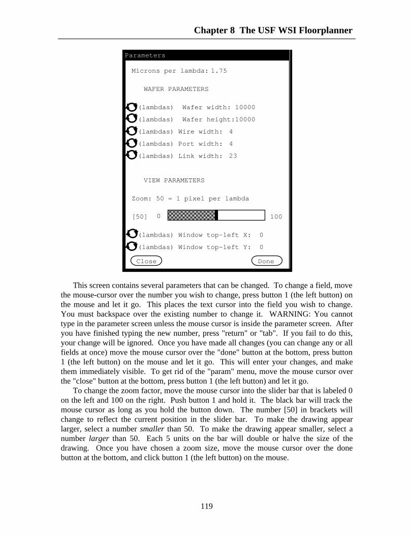
Chapter 8 The USF WSI Floorplanner
119
Microns per lambda: 1.75
WAFER PARAMETERS
(lambdas) Wafer width:
(lambdas) Wafer height:
(lambdas) Wire width:
(lambdas) Port width:
(lambdas) Link width:
VIEW PARAMETERS
Zoom: 50 = 1 pixel per lambda
[50]
(lambdas) Window top-left X:
(lambdas) Window top-left Y:
10000
10000
4
4
23
0
0
AAAAAAAAAAAAAAAAAAAAAAAAAAAAAAAAAAAA
AAAAAAAAAAAAAAAAAAAAAAAAAAAAAAAAAAAA
AAAAAAAAAAAAAAAAAAAAAAAAAAAAAAAAAAAA
AAAAAAAAAAAAAAAAAAAAAAAAAAAAAAAAAAAA
AAAAAAAAAAAAAAAAAAAAAAAAAAAAAAAAAAAA
AAAAAAAAAAAAAAAAAAAAAAAAAAAAAAAAAAAA
AAAAAAAAAAAAAAAAAAAAAAAAAAAAAAAAAAAA
AAAAAAAAAAAAAAAAAAAAAAAAAAAAAAAAAAAA
AAAAAAAAAAAAAAAAAAAAAAAAAAAAAAAAAAAA
AAAAAAAAAAAAAAAAAA
0 100
DoneClose
Parameters
This screen contains several parameters that can be changed. To change a field, movethe mouse-cursor over the number you wish to change, press button 1 (the left button) onthe mouse and let it go. This places the text cursor into the field you wish to change.You must backspace over the existing number to change it. WARNING: You cannottype in the parameter screen unless the mouse cursor is inside the parameter screen. Afteryou have finished typing the new number, press "return" or "tab". If you fail to do this,your change will be ignored. Once you have made all changes (you can change any or allfields at once) move the mouse cursor over the "done" button at the bottom, press button1 (the left button) on the mouse and let it go. This will enter your changes, and makethem immediately visible. To get rid of the "param" menu, move the mouse cursor overthe "close" button at the bottom, press button 1 (the left button) and let it go.
To change the zoom factor, move the mouse cursor into the slider bar that is labeled 0on the left and 100 on the right. Push button 1 and hold it. The black bar will track themouse cursor as long as you hold the button down. The number [50] in brackets willchange to reflect the current position in the slider bar. To make the drawing appearlarger, select a number smaller than 50. To make the drawing appear smaller, select anumber larger than 50. Each 5 units on the bar will double or halve the size of thedrawing. Once you have chosen a zoom size, move the mouse cursor over the donebutton at the bottom, and click button 1 (the left button) on the mouse.

Chapter 8 The USF WSI Floorplanner
120
The "param" menu listed above is displayed when no object is selected, or when alink is selected. When some other object is selected, object parameters are also displayedin the "param" menu. In this case the "param" menu will look as follows.
Microns per lambda: 1.75
WAFER PARAMETERS
(lambdas) Wafer width:
(lambdas) Wafer height:
(lambdas) Wire width:
(lambdas) Port width:
(lambdas) Link width:
VIEW PARAMETERS
Zoom: 50 = 1 pixel per lambda
[50]
(lambdas) Window top-left X:
(lambdas) Window top-left Y:
10000
10000
4
4
23
0
0
AAAAAAAAAAAAAAAAAAAAAAAAAAAAAAAAAAAA
AAAAAAAAAAAAAAAAAAAAAAAAAAAAAAAAAAAA
AAAAAAAAAAAAAAAAAAAAAAAAAAAAAAAAAAAA
AAAAAAAAAAAAAAAAAAAAAAAAAAAAAAAAAAAA
AAAAAAAAAAAAAAAAAAAAAAAAAAAAAAAAAAAA
AAAAAAAAAAAAAAAAAAAAAAAAAAAAAAAAAAAA
AAAAAAAAAAAAAAAAAAAAAAAAAAAAAAAAAAAA
AAAAAAAAAAAAAAAAAAAAAAAAAAAAAAAAAAAA
AAAAAAAAAAAAAAAAAAAAAAAAAAAAAAAAAAAA
AAAAAAAAAAAAAAAAAA
0 100
DoneClose
Parameters
OBJECT PARAMETERS
(lambdas) Top-left Corner X:
(lambdas) Top-left Corner Y:
(lambdas) Height:
(lambdas) Width:
[TILE]
100
100
50
50
The following is a list of all the fields in the "param" menu and their meanings.
(lambdas) Click on this field to change the units of the field to the right fromlambdas to microns. (Internally all values are kept in lambdas). Whenclicked, this field changes to "(microns)". The current value of "Micronsper lambda" is used to recalculate field values.

Chapter 8 The USF WSI Floorplanner
121
(microns) Click on this field to change the units of the field to the right frommicrons to lambdas. (Internally all values are kept in lambdas). Whenclicked, this field changes to "(lambdas)".
Microns per Lambda This affects only the conversion factor for those fields that arespecified in microns. Changing this field causes the units for all otherfields to change to "(lambdas)". Since all internal values are kept inlambdas, this does not affect the drawing. In the future this will affectlayout extraction.
Wafer width The width of the wafer in lambdas or microns.
Wafer height The height of the wafer in lambdas or microns.
Wire width The assumed width of all wires. Wires are always drawn one pixel wide.This has no effect at present, but in the future will affect layoutextraction. It applies to all wires, new and already drawn.
Port width The actual width of a port. Ports are always drawn square. This affectsonly new ports. Old ports retain their previous size.
Link width The assumed width of a link. Internally links have no width, so links areunaffected by this parameter. HOWEVER, wires must be separated by atleast the width of one link, so this will affect how far apart wires can bedrawn.
Window Top-Left X The x coordinate in the wafer of the upper left corner of thewindow. Changing this changes the position of the wafer in the window
Window Top-Left Y The y coordinate in the wafer of the upper left corner of thewindow. Changing this changes the position of the wafer in the window
Top-Left Corner X The x coordinate of the upper left coordinate of the selected object.This coordinate appears when the selected object is a block, a tile, or aport. Coordinates are wafer coordinates.
Top-Left Corner Y The y coordinate of the upper left coordinate of the selected object.This coordinate appears when the selected object is a block, a tile, or aport. Coordinates are wafer coordinates.
Height The height of the selected object. This field appears for blocks and tiles.
Width The width of the selected object. This field appears for blocks and tiles.
Endpoint X The x coordinate of the starting point of a line. Lines run right or downfrom their starting points.

Chapter 8 The USF WSI Floorplanner
122
Endpoint Y The y coordinate of the starting point of a line. Lines run right or downfrom their starting points.
Length The length of a line. Lines run right or down from their starting points.
Direction This field appears only for selected lines and has the value "horiz" or"vert". Click on the field to change from one to the other.
Zoom Zoom in and out. See above for instructions on how to operate the slider.
Done Clicking this button "accepts" any changes you have made, and alters thedisplay.
Close Clicking this button makes the "param" menu disappear. Any unacceptedchanges will be purged.
8.3.4 The Array MenuThe array menu is used to create an array of wires, tiles, ports, or blocks. To use the
array menu, first select the object to be arrayed (see section 5). Then move the mousecursor over the word "Array" at the top of the screen. Press button 1 (the left button) onthe mouse and let it go. The following menu will appear.
ARRAY TILE
RIGHT Occurences: Separation:
DOWN Occurences: Separation:
LEFT Occurences: Separation:
UP Occurences: Separation:
ARRAY TYPE Instance
DoneCancel
The first line of this menu gives the name of the type of object selected. If you haveselected a link, you may continue, but nothing will happen. Links cannot be arrayed.Decide which direction you wish the array to go, and how many occurences you want, notcounting the selected object. When the selected object is a vertical wire, only LEFT andRIGHT directions should be used. When the selected object is a horizontal wire only UPand DOWN should be used. Similarly, when the selected object is a port, only LEFT andRIGHT or UP and DOWN should be used depending on whether the port is on ahorizontal or vertical block-edge. Tiles and blocks may be arrayed in several directions atonce. If two orthogonal directions such as RIGHT and DOWN are chosen, the quadrantwill also be filled in.

Chapter 8 The USF WSI Floorplanner
123
If you do not specify a separation, the assumed separation is zero. For tiles this is ok.For wires, ports, and blocks you will need to calculate the separation between objects.
The field "ARRAY TYPE" has effect only for tiles. By default the array copies oftiles are instances of the selected tile. However you can make them copies by clicking theword "instance". When you do this, it changes to "copy". Click the word "copy" tochange it back to instance.
After you have entered all your data, move the mouse cursor over the button "done",press button 1 (the left button) on the mouse and let it go. This will cause the arrayoperation to take place, and will make the array menu disappear. If you change yourmind about arraying, move the mouse cursor over the button "cancel", press button 1 (theleft button) and let it go. This will make the menu disappear without performing the arrayoperation.
8.4 The Scroll BarsOnly the vertical scroll bar will be described here, the horizontal scroll bar is
identical. The scroll bar has five locations, the up arrow, the down arrow, inside thewhite box, above the white box, and below the white box. The position of the white boxindicates the current position within the wafer being edited. (See the param menu for theexact location.) Clicking in the up arrow moves the window up five pixels (the waferwill move down). Clicking in the down arrow moves the window down five pixels.Holding button 1 down in either arrow causes the operation to repeat five times a secondafter the first second. Large screens will scroll slower. When scrolling with arrows, thescreen is not repainted until button 1 is released, so white area will move into theunoccupied part of the screen, even if there is really something there.
Clicking above the white box moves the window up one screenful. Clicking belowthe white box moves the window down one screenful. This operation does not repeat ifthe button is held down. This is the best way to scan down a wafer quickly withoutmissing anything.
Pushing button 1 down and holding it inside the white box causes the white box totrack the cursor. The final position of the box is determined by releasing the button. Thescreen will not be redrawn until the button is released. This is the fastest way to movelarge distances.
8.5 Selecting, Moving, and Resizing ObjectsTo select an object, choose select mode from the drawing-mode bar at the left of the
screen. Then move the cursor to the object you want to select, and click button 1 (the leftbutton). The object should change color. You cannot select a wire, port, block, or linkunless the tile containing it is already selected. To select these objects requires twoclicks, one to select the tile, and one to select the object. Clicking in a white areaunselects everything. The color of an object determines whether it is selected. Anunselected tile is grey with blue wires, yellow-green blocks, red ports and light-greenlinks. A selected tile is pink with brown wires, orange blocks, dark green ports andpurple links. When an object is selected within the currently selected tile, it changes backto its unselected-tile color. Thus a selected block is yellow-green with red ports, aselected port is red (in an orange block), a selected wire is blue, and a selected link is

Chapter 8 The USF WSI Floorplanner
124
light-green. The last object drawn is automatically selected until another object is drawnor until another selection is made.
When an object is selected, resizing handles appear at the corners, or at the end ofwires. (Since links cannot be resized, no handles appear.) The currently selected objectcan be resized or moved regardless of the current drawing mode. To move the currentlyselected object, move the mouse cursor over the object, not inside the resizing handles,and press button 2 (the middle button) on the mouse and hold it. The object will movewith the mouse cursor until the button is released. If the final position of the object isillegal (overlapping tiles, etc.) the object will jump back to its original position.Otherwise the object will move to the new position.
To resize an object, move the mouse cursor into one of the resizing handles, pressbutton 2 (the middle button) on the mouse and hold it. The corner of the object, or theend of the wire will move with the mouse cursor until the button is released. The objectwill not be resized if its new position is illegal. For blocks, ports, and tiles it is alsopossible to resize an edge rather than a corner. Move the mouse cursor between tworesizing handles, press button 2, and hold it. The edge of the object will move with thecursor until the button is released. Ports always resize to the smallest square that touchestwo opposite edges of the new rectangle. When wires and ports are resized or moved,they align themselves with any port or wire they may touch.
8.6 ConclusionThe floorplanner is your tool. Report any bugs, problems, or inconveniences to Peter
M. Maurer (813) 974-4758.

125
CHAPTER 9
The Wave-Form Generator
9.1 IntroductionThe FHDL wave-form generator is designed to be used in conjunction with the FHDL
driver, in either its compiled or interpreted form. The wave-form generator allows theoutputs of a simulation to be graphed as wave-forms. To use the wave-form generator,you must be logged onto a SUN work station, and must be running suntools.
9.2 Invoking The GeneratorTo invoke the wave-form generator, use the following driver command. (This
command can be used either interactively, or in the compiled driver.)
attach <n>,wave
The operand <n> must be a number from 1 through 10 (or an expression thatevaluates to a number). Furthermore the number must be at least one larger than thenumber of arguments specified on the command that invoked the simulator. If no errormessages are produced as a result of this command, the following screen will appear.

Chapter 9 The Wave Form Generator
126
AAAAAAAAAAAAAAAAAAAAAAAAAAAAAAAAAAAAAAAA
AAAAAAAAAAAAAAAAAAAAAAAAAAAAAAAAAAAAAAAA
AAAAAAAAAAAAAAAAAAAAAAAAAAAAAAAAAAAAAAAA
AAAAAAAAAAAAAAAAAAAAAAAAAAAAAAAAAAAAAAAA
AAAAAAAAAAAAAAAAAAAAAAAAAAAAAAAAAAAAAAAA
AAAAAAAAAAAAAAAAAAAAAAAAAAAAAAAAAAAAAAAA
AAAAAAAAAAAAAAAAAAAAAAAAAAAAAAAAAAAAAAAA
AAAAAAAAAAAAAAAAAAAAAAAAAAAAAAAAAAAAAAAA
AAAAAAAAAAAAAAAAAAAAAAAAAAAAAAAAAAAAAAAA
AAAAAAAAAAAAAAAAAAAAAAAAAAAAAAAAAAAAAAAA
AAAAAAAAAAAAAAAAAAAAAAAAAAAAAAAAAAAAAAAA
AAAAAAAAAAAAAAAAAAAAAAAAAAAAAAAAAAAAAAAA
AAAAAAAAAAAAAAAAAAAAAAAAAAAAAAAAAAAAAAAA
AAAAAAAAAAAAAAAAAAAAAAAAAAAAAAAAAAAAAAAA
AAAAAAAAAAAAAAAAAAAAAAAAAAAAAAAAAAAAAAAA
AAAAAAAAAAAAAAAAAAAAAAAAAAAAAAAAAAAAAAAA
AAAAAAAAAAAAAAAAAAAAAAAAAAAAAAAAAAAAAAAA
AAAAAAAAAAAAAAAAAAAAAAAAAAAAAAAAAAAAAAAA
AAAAAAAAAAAAAAAAAAAAAAAAAAAAAAAAAAAAAAAA
AAAAAAAAAAAAAAAAAAAAAAAAAAAAAAAAAAAAAAAA
AAAAAAAAAAAAAAAAAAAAAAAAAAAAAAAAAAAAAAAA
AAAAAAAAAAAAAAAAAAAAAAAAAAAAAAAAAAAAAAAA
AAAAAAAAAAAAAAAAAAAAAAAAAAAAAAAAAAAAAAAA
AAAAAAAAAAAAAAAAAAAAAAAAAAAAAAAAAAAAAAAA
AAAAAAAAAAAAAAAAAAAAAAAAAAAAAAAAAAAAAAAA
AAAAAAAAAAAAAAAAAAAAAAAAAAAAAAAAAAAAAAAA
AAAAAAAAAAAAAAAAAAAAAAAAAAAAAAAAAAAAAAAA
AAAAAAAAAAAAAAAAAAAAAAAAAAAAAAAAAAAAAAAA
AAAAAAAAAAAAAAAAAAAAAAAAAAAAAAAAAAAAAAAA
AAAAAAAAAAAAAAAAAAAAAAAAAAAAAAAAAAAAAAAA
AAAAAAAAAAAAAAAAAAAAAAAAAAAAAAAAAAAAAAAA
AAAAAAAAAAAAAAAAAAAAAAAAAAAAAAAAAAAAAAAA
AAAAAAAAAAAAAAAAAAAAAAAAAAAAAAAAAAAAAAAA
AAAAAAAAAAAAAAAAAAAAAAAAAAAAAAAAAAAAAAAA
AAAAAAAAAAAAAAAAAAAAAAAAAAAAAAAAAAAAAAAA
AAAAAAAAAAAAAAAAAAAAAAAAAAAAAAAAAAAAAAAA
AAAAAAAAAAAAAAAAAAAAAAAAAAAAAAAAAAAAAAAA
AAAAAAAAAAAAAAAAAAAAAAAAAAAAAAAAAAAAAAAA
AAAAAAAAAAAAAAAAAAAAAAAAAAAAAAAAAAAAAAAA
AAAAAAAAAAAAAAAAAAAAAAAAAAAAAAAAAAAAAAAA
AAAAAAAAAAAAAAAAAAAAAAAAAAAAAAAAAAAAAAAA
AAAAAAAAAAAAAAAAAAAAAAAAAAAAAAAAAAAAAAAA
AAAAAAAAAAAAAAAAAAAAAAAAAAAAAAAAAAAAAAAA
AAAAAAAAAAAAAAAAAAAAAAAAAAAAAAAAAAAAAAAA
AAAAAAAAAAAAAAAAAAAAAAAAAAAAAAAAAAAAAAAA
AAAAAAAAAAAAAAAAAAAAAAAAAAAAAAAAAAAAAAAA
AAAAAAAAAAAAAAAAAAAAAAAAAAAAAAAAAAAAAAAA
AAAAAAAAAAAAAAAAAAAAAAAAAAAAAAAAAAAAAAAA
AAAAAAAAAAAAAAAAAAAAAAAAAAAAAAAAAAAAAAAA
AAAAAAAAAAAAAAAAAAAAAAAAAAAAAAAAAAAAAAAAAAAAAAAAAAAAAAAAAAAAAAAAAAAAAAAAAAAAAAAAAAAAAAAAAAAAAAAAAAAAAAAAAAAAAAAAAAAAAAAAAAAAAAAAAAAAAAAAAAAAAAAAAAAAAAAAAAAAAAAAAAAAAAAAAAAAAAAAAAAAAAAAAAAAAAAAAAAAAAAAAAAAAAAAAAAAAAAAAAAAAAAAAAAAAAAAAAAAAAAAAAAAAAAAAAAAAAAAAAAAAAAAAAAAAAAAAAAAAAAAAAAAAAAAAAAAAAAAAAAAAAAAAAAAAAAAAAAAAAAAAAAAAAAAAAAAAAAAAAAAAAAAAAAAAAAAAAAAAAAAAAAAAAAAAAAAAAAAAAAAAA
AAAAAAAAAAAAAAAAAAAAAAAAAAAAAAAAAAAAAAAAAAAAAAAAAAAAAAAAAAAAAAAAAAAAAAAAAAAAAAAAAAAAAAAAAAAAAAAAAAAAAAAAAAAAAAAAAAAAAAAAAAAAAAAAAAAAAAAAAAAAAAAAAAAAAAAAAAAAAAAAAAAAAAAAAAAAAAAAAAAAAAAAAAAAAAAAAAAAAAAAAAAAAAAAAAAAAAAAAAAAAAAAAAAAAAAAAAAAAAAAAAAAAAAAAAAAAAAAAAAAAAAAAAAAAAAAAAAAAAAAAAAAAAAAAAAAAAAAAAAAAAAAAAAAAAAAAAAAAAAAAAAAAAAAAAAAAAAAAAAAAAAAAAAAAAAA
AAAAAAAAAAAAAAAAAAAAAAAAAAAAAAAAAAAAAAAAAAAAAAAAAAAAAAAAAAAAAAAAAAAAAAAAAAAAAAAAAAAAAAAAAAAAAAAAAAAAAAAAAAAAAAAAAAAAAAAAAAAAAAAAAAAAAAAAAAAAAAAAAAAAAAAAAAAAAAAAAAAAAAAAAAAAAAAAAAAAAAAAAAAAAAAAAAAAAAAAAAAAAAAAAAAAAAAAAAAAAAAAAAAAAAAAAAAAAAAAAAAAAAAAAAAAAAAAAAAAAAAA
File Edit Param ArrayAAAAAAAAAAAAAAAAAAAAAAAAAAAAAAAAAAAAAAAAAAAAAAAAAAAAAAAAAAAAAAAAAAAAAAAAA AAA
AA
A AA AA AA AA AA AA AA AA AA AA AA AA AA AA AAA
AA
A AA AA AA AA AA AA AA AA AA AA AA AA AA AA AAA
AA
A AA AA AA AA AA AA AA AA AA AA AA AA AA AA AAA
AA
A AA AA AA AA AA AA AA AA AA AA AA AA AA AA AAA
AA
A AA AA AA AA AA AA AA AA AA AA AA AA AA AA AAA
AA
A AA AA AA AA AA AA AA AA AA AA AA AA AA AA AAA
AA
A AA AAAAAAAAAAAAAAAAAAAAAAAAAAAAAAAAAAAAAAAAAAAAAAAAAAAAAAAAAAAAAAAAA
Wave
The next step is to decide which signals (or variables) you want to graph on thedisplay, and list them in the following command.
monitor <n>,sig1,sig2,sig3,...,sigN
The number <n> must be the same number specified in the "attach" command. Thenames "sig1" through "sigN" are the names of the signals you wish to monitor. Forconcreteness, let's assume that you wish to monitor signals a, b, and c, and that a and bare width 1, while c is of width 2. You would issue the following command.
monitor <n>,a,b,c
In response to this command, the following change appears in the screen.

Chapter 9 The Wave Form Generator
127
AAAAAAAAAAAAAAAAAAAAAAAAAAAAAAAAAAAAAAAA
AAAAAAAAAAAAAAAAAAAAAAAAAAAAAAAAAAAAAAAA
AAAAAAAAAAAAAAAAAAAAAAAAAAAAAAAAAAAAAAAA
AAAAAAAAAAAAAAAAAAAAAAAAAAAAAAAAAAAAAAAA
AAAAAAAAAAAAAAAAAAAAAAAAAAAAAAAAAAAAAAAA
AAAAAAAAAAAAAAAAAAAAAAAAAAAAAAAAAAAAAAAA
AAAAAAAAAAAAAAAAAAAAAAAAAAAAAAAAAAAAAAAA
AAAAAAAAAAAAAAAAAAAAAAAAAAAAAAAAAAAAAAAA
AAAAAAAAAAAAAAAAAAAAAAAAAAAAAAAAAAAAAAAA
AAAAAAAAAAAAAAAAAAAAAAAAAAAAAAAAAAAAAAAA
AAAAAAAAAAAAAAAAAAAAAAAAAAAAAAAAAAAAAAAA
AAAAAAAAAAAAAAAAAAAAAAAAAAAAAAAAAAAAAAAA
AAAAAAAAAAAAAAAAAAAAAAAAAAAAAAAAAAAAAAAA
AAAAAAAAAAAAAAAAAAAAAAAAAAAAAAAAAAAAAAAA
AAAAAAAAAAAAAAAAAAAAAAAAAAAAAAAAAAAAAAAA
AAAAAAAAAAAAAAAAAAAAAAAAAAAAAAAAAAAAAAAA
AAAAAAAAAAAAAAAAAAAAAAAAAAAAAAAAAAAAAAAA
AAAAAAAAAAAAAAAAAAAAAAAAAAAAAAAAAAAAAAAA
AAAAAAAAAAAAAAAAAAAAAAAAAAAAAAAAAAAAAAAA
AAAAAAAAAAAAAAAAAAAAAAAAAAAAAAAAAAAAAAAA
AAAAAAAAAAAAAAAAAAAAAAAAAAAAAAAAAAAAAAAA
AAAAAAAAAAAAAAAAAAAAAAAAAAAAAAAAAAAAAAAA
AAAAAAAAAAAAAAAAAAAAAAAAAAAAAAAAAAAAAAAA
AAAAAAAAAAAAAAAAAAAAAAAAAAAAAAAAAAAAAAAA
AAAAAAAAAAAAAAAAAAAAAAAAAAAAAAAAAAAAAAAA
AAAAAAAAAAAAAAAAAAAAAAAAAAAAAAAAAAAAAAAA
AAAAAAAAAAAAAAAAAAAAAAAAAAAAAAAAAAAAAAAA
AAAAAAAAAAAAAAAAAAAAAAAAAAAAAAAAAAAAAAAA
AAAAAAAAAAAAAAAAAAAAAAAAAAAAAAAAAAAAAAAA
AAAAAAAAAAAAAAAAAAAAAAAAAAAAAAAAAAAAAAAA
AAAAAAAAAAAAAAAAAAAAAAAAAAAAAAAAAAAAAAAA
AAAAAAAAAAAAAAAAAAAAAAAAAAAAAAAAAAAAAAAA
AAAAAAAAAAAAAAAAAAAAAAAAAAAAAAAAAAAAAAAA
AAAAAAAAAAAAAAAAAAAAAAAAAAAAAAAAAAAAAAAA
AAAAAAAAAAAAAAAAAAAAAAAAAAAAAAAAAAAAAAAA
AAAAAAAAAAAAAAAAAAAAAAAAAAAAAAAAAAAAAAAA
AAAAAAAAAAAAAAAAAAAAAAAAAAAAAAAAAAAAAAAA
AAAAAAAAAAAAAAAAAAAAAAAAAAAAAAAAAAAAAAAA
AAAAAAAAAAAAAAAAAAAAAAAAAAAAAAAAAAAAAAAA
AAAAAAAAAAAAAAAAAAAAAAAAAAAAAAAAAAAAAAAA
AAAAAAAAAAAAAAAAAAAAAAAAAAAAAAAAAAAAAAAA
AAAAAAAAAAAAAAAAAAAAAAAAAAAAAAAAAAAAAAAA
AAAAAAAAAAAAAAAAAAAAAAAAAAAAAAAAAAAAAAAA
AAAAAAAAAAAAAAAAAAAAAAAAAAAAAAAAAAAAAAAA
AAAAAAAAAAAAAAAAAAAAAAAAAAAAAAAAAAAAAAAA
AAAAAAAAAAAAAAAAAAAAAAAAAAAAAAAAAAAAAAAA
AAAAAAAAAAAAAAAAAAAAAAAAAAAAAAAAAAAAAAAA
AAAAAAAAAAAAAAAAAAAAAAAAAAAAAAAAAAAAAAAA
AAAAAAAAAAAAAAAAAAAAAAAAAAAAAAAAAAAAAAAA
AAAAAAAAAAAAAAAAAAAAAAAAAAAAAAAAAAAAAAAAAAAAAAAAAAAAAAAAAAAAAAAAAAAAAAAAAAAAAAAAAAAAAAAAAAAAAAAAAAAAAAAAAAAAAAAAAAAAAAAAAAAAAAAAAAAAAAAAAAAAAAAAAAAAAAAAAAAAAAAAAAAAAAAAAAAAAAAAAAAAAAAAAAAAAAAAAAAAAAAAAAAAAAAAAAAAAAAAAAAAAAAAAAAAAAAAAAAAAAAAAAAAAAAAAAAAAAAAAAAAAAAAAAAAAAAAAAAAAAAAAAAAAAAAAAAAAAAAAAAAAAAAAAAAAAAAAAAAAAAAAAAAAAAAAAAAAAAAAAAAAAAAAAAAAAAAAAAAAAAAAAAAAAAAAAAAAAAAAAAAAA
AAAAAAAAAAAAAAAAAAAAAAAAAAAAAAAAAAAAAAAAAAAAAAAAAAAAAAAAAAAAAAAAAAAAAAAAAAAAAAAAAAAAAAAAAAAAAAAAAAAAAAAAAAAAAAAAAAAAAAAAAAAAAAAAAAAAAAAAAAAAAAAAAAAAAAAAAAAAAAAAAAAAAAAAAAAAAAAAAAAAAAAAAAAAAAAAAAAAAAAAAAAAAAAAAAAAAAAAAAAAAAAAAAAAAAAAAAAAAAAAAAAAAAAAAAAAAAAAAAAAAAAAAAAAAAAAAAAAAAAAAAAAAAAAAAAAAAAAAAAAAAAAAAAAAAAAAAAAAAAAAAAAAAAAAAAAAAAAAAAAAAAAAAAAAAAA
AAAAAAAAAAAAAAAAAAAAAAAAAAAAAAAAAAAAAAAAAAAAAAAAAAAAAAAAAAAAAAAAAAAAAAAAAAAAAAAAAAAAAAAAAAAAAAAAAAAAAAAAAAAAAAAAAAAAAAAAAAAAAAAAAAAAAAAAAAAAAAAAAAAAAAAAAAAAAAAAAAAAAAAAAAAAAAAAAAAAAAAAAAAAAAAAAAAAAAAAAAAAAAAAAAAAAAAAAAAAAAAAAAAAAAAAAAAAAAAAAAAAAAAAAAAAAAAAAAAAAAAA
File Edit Param ArrayAAAAAAAAAAAAAAAAAAAAAAAAAAAAAAAAAAAAAAAAAAAAAAAAAAAAAAAAAAAAAAAAAAAAAAAAA AAA
AA
A AA AA AA AA AA AA AA AA AA AA AA AA AA AA AAA
AA
A AA AA AA AA AA AA AA AA AA AA AA AA AA AA AAA
AA
A AA AA AA AA AA AA AA AA AA AA AA AA AA AA AAA
AA
A AA AA AA AA AA AA AA AA AA AA AA AA AA AA AAA
AA
A AA AA AA AA AA AA AA AA AA AA AA AA AA AA AAA
AA
A AA AA AA AA AA AA AA AA AA AA AA AA AA AA AAA
AA
A AA AAAAAAAAAAAAAAAAAAAAAAAAAAAAAAAAAAAAAAAAAAAAAAAAAAAAAAAAAAAAAAAAA
Wave
a
b
c
If you wish, you may issue several "monitor" commands. The screen will be updatedto include the new signals after each "monitor" command. Now you are ready to simulateyour circuit. Assume that you simulate the circuit for four phases using the followingcommand.
go 4
Assume that "a" starts at zero in phase 1, and toggles between 1 and 0 each phase.Assume further that "b" starts at one and changes to zero in the third phase and that cstarts at "10" and changes to "01" in the third phase. The result will be displayed asfollows. Note that width-1 signals are displayed as lines that rise and fall with the valueof the signal, while multi-width signals are displayed as grey bars with an X at the pointwhere the value changes. Along the top of the display you will notice vector numbers atthe head of each column. (They are not shown in the figures.)
When a signal is displayed as a grey bar, you can find out what the real value is bymoving the mouse cursor into the part of the grey bar you are curious about, pressingbutton 1 (the left button) on the mouse and holding it. As long as you hold the buttondown, a miniature window containing the signal name, vector number, and value will bedisplayed. You can do the same thing with single-bit signals to verify the vector numberat a point of change. When you release button 1, the miniature window disappears.Moving the cursor without releasing the button will not change the value displayed in thewindow.

Chapter 9 The Wave Form Generator
128
AAAAAAAAAAAAAAAAAAAAAAAAAAAAAAAAAAAAAAAA
AAAAAAAAAAAAAAAAAAAAAAAAAAAAAAAAAAAAAAAA
AAAAAAAAAAAAAAAAAAAAAAAAAAAAAAAAAAAAAAAA
AAAAAAAAAAAAAAAAAAAAAAAAAAAAAAAAAAAAAAAA
AAAAAAAAAAAAAAAAAAAAAAAAAAAAAAAAAAAAAAAA
AAAAAAAAAAAAAAAAAAAAAAAAAAAAAAAAAAAAAAAA
AAAAAAAAAAAAAAAAAAAAAAAAAAAAAAAAAAAAAAAA
AAAAAAAAAAAAAAAAAAAAAAAAAAAAAAAAAAAAAAAA
AAAAAAAAAAAAAAAAAAAAAAAAAAAAAAAAAAAAAAAA
AAAAAAAAAAAAAAAAAAAAAAAAAAAAAAAAAAAAAAAA
AAAAAAAAAAAAAAAAAAAAAAAAAAAAAAAAAAAAAAAA
AAAAAAAAAAAAAAAAAAAAAAAAAAAAAAAAAAAAAAAA
AAAAAAAAAAAAAAAAAAAAAAAAAAAAAAAAAAAAAAAA
AAAAAAAAAAAAAAAAAAAAAAAAAAAAAAAAAAAAAAAA
AAAAAAAAAAAAAAAAAAAAAAAAAAAAAAAAAAAAAAAA
AAAAAAAAAAAAAAAAAAAAAAAAAAAAAAAAAAAAAAAA
AAAAAAAAAAAAAAAAAAAAAAAAAAAAAAAAAAAAAAAA
AAAAAAAAAAAAAAAAAAAAAAAAAAAAAAAAAAAAAAAA
AAAAAAAAAAAAAAAAAAAAAAAAAAAAAAAAAAAAAAAA
AAAAAAAAAAAAAAAAAAAAAAAAAAAAAAAAAAAAAAAA
AAAAAAAAAAAAAAAAAAAAAAAAAAAAAAAAAAAAAAAA
AAAAAAAAAAAAAAAAAAAAAAAAAAAAAAAAAAAAAAAA
AAAAAAAAAAAAAAAAAAAAAAAAAAAAAAAAAAAAAAAA
AAAAAAAAAAAAAAAAAAAAAAAAAAAAAAAAAAAAAAAA
AAAAAAAAAAAAAAAAAAAAAAAAAAAAAAAAAAAAAAAA
AAAAAAAAAAAAAAAAAAAAAAAAAAAAAAAAAAAAAAAA
AAAAAAAAAAAAAAAAAAAAAAAAAAAAAAAAAAAAAAAA
AAAAAAAAAAAAAAAAAAAAAAAAAAAAAAAAAAAAAAAA
AAAAAAAAAAAAAAAAAAAAAAAAAAAAAAAAAAAAAAAA
AAAAAAAAAAAAAAAAAAAAAAAAAAAAAAAAAAAAAAAA
AAAAAAAAAAAAAAAAAAAAAAAAAAAAAAAAAAAAAAAA
AAAAAAAAAAAAAAAAAAAAAAAAAAAAAAAAAAAAAAAA
AAAAAAAAAAAAAAAAAAAAAAAAAAAAAAAAAAAAAAAA
AAAAAAAAAAAAAAAAAAAAAAAAAAAAAAAAAAAAAAAA
AAAAAAAAAAAAAAAAAAAAAAAAAAAAAAAAAAAAAAAA
AAAAAAAAAAAAAAAAAAAAAAAAAAAAAAAAAAAAAAAA
AAAAAAAAAAAAAAAAAAAAAAAAAAAAAAAAAAAAAAAA
AAAAAAAAAAAAAAAAAAAAAAAAAAAAAAAAAAAAAAAA
AAAAAAAAAAAAAAAAAAAAAAAAAAAAAAAAAAAAAAAA
AAAAAAAAAAAAAAAAAAAAAAAAAAAAAAAAAAAAAAAA
AAAAAAAAAAAAAAAAAAAAAAAAAAAAAAAAAAAAAAAA
AAAAAAAAAAAAAAAAAAAAAAAAAAAAAAAAAAAAAAAA
AAAAAAAAAAAAAAAAAAAAAAAAAAAAAAAAAAAAAAAA
AAAAAAAAAAAAAAAAAAAAAAAAAAAAAAAAAAAAAAAA
AAAAAAAAAAAAAAAAAAAAAAAAAAAAAAAAAAAAAAAA
AAAAAAAAAAAAAAAAAAAAAAAAAAAAAAAAAAAAAAAA
AAAAAAAAAAAAAAAAAAAAAAAAAAAAAAAAAAAAAAAA
AAAAAAAAAAAAAAAAAAAAAAAAAAAAAAAAAAAAAAAA
AAAAAAAAAAAAAAAAAAAAAAAAAAAAAAAAAAAAAAAA
AAAAAAAAAAAAAAAAAAAAAAAAAAAAAAAAAAAAAAAAAAAAAAAAAAAAAAAAAAAAAAAAAAAAAAAAAAAAAAAAAAAAAAAAAAAAAAAAAAAAAAAAAAAAAAAAAAAAAAAAAAAAAAAAAAAAAAAAAAAAAAAAAAAAAAAAAAAAAAAAAAAAAAAAAAAAAAAAAAAAAAAAAAAAAAAAAAAAAAAAAAAAAAAAAAAAAAAAAAAAAAAAAAAAAAAAAAAAAAAAAAAAAAAAAAAAAAAAAAAAAAAAAAAAAAAAAAAAAAAAAAAAAAAAAAAAAAAAAAAAAAAAAAAAAAAAAAAAAAAAAAAAAAAAAAAAAAAAAAAAAAAAAAAAAAAAAAAAAAAAAAAAAAAAAAAAAAAAAAAAAA
AAAAAAAAAAAAAAAAAAAAAAAAAAAAAAAAAAAAAAAAAAAAAAAAAAAAAAAAAAAAAAAAAAAAAAAAAAAAAAAAAAAAAAAAAAAAAAAAAAAAAAAAAAAAAAAAAAAAAAAAAAAAAAAAAAAAAAAAAAAAAAAAAAAAAAAAAAAAAAAAAAAAAAAAAAAAAAAAAAAAAAAAAAAAAAAAAAAAAAAAAAAAAAAAAAAAAAAAAAAAAAAAAAAAAAAAAAAAAAAAAAAAAAAAAAAAAAAAAAAAAAAAAAAAAAAAAAAAAAAAAAAAAAAAAAAAAAAAAAAAAAAAAAAAAAAAAAAAAAAAAAAAAAAAAAAAAAAAAAAAAAAAAAAAAAAA
AAAAAAAAAAAAAAAAAAAAAAAAAAAAAAAAAAAAAAAAAAAAAAAAAAAAAAAAAAAAAAAAAAAAAAAAAAAAAAAAAAAAAAAAAAAAAAAAAAAAAAAAAAAAAAAAAAAAAAAAAAAAAAAAAAAAAAAAAAAAAAAAAAAAAAAAAAAAAAAAAAAAAAAAAAAAAAAAAAAAAAAAAAAAAAAAAAAAAAAAAAAAAAAAAAAAAAAAAAAAAAAAAAAAAAAAAAAAAAAAAAAAAAAAAAAAAAAAAAAAAAAA
File Edit Param ArrayAAAAAAAAAAAAAAAAAAAAAAAAAAAAAAAAAAAAAAAAAAAAAAAAAAAAAAAAAAAAAAAAAAAAAAAAA AAA
AA
A AA AA AA AA AA AA AA AA AA AA AA AA AA AA AAA
AA
A AA AA AA AA AA AA AA AA AA AA AA AA AA AA AAA
AA
A AA AA AA AA AA AA AA AA AA AA AA AA AA AA AAA
AA
A AA AA AA AA AA AA AA AA AA AA AA AA AA AA AAA
AA
A AA AA AA AA AA AA AA AA AA AA AA AA AA AA AAA
AA
A AA AA AA AA AA AA AA AA AA AA AA AA AA AA AAA
AA
A AA AAAAAAAAAAAAAAAAAAAAAAAAAAAAAAAAAAAAAAAAAAAAAAAAAAAAAAAAAAAAAAAAA
Wave
a
b
cAAAAAAAAAAAAAAAAAAAAAAAAAAAAAAAAAAAA
AAAAAAAAAAAAAAAAAAAAAAAAAAAAAAAAAAAA
AAAAAAAAAAAAAAAAAAAAAAAAAAAAAAAAAAAA
AAAAAAAAAAAAAAAAAAAAAAAAAAAAAAAAAAAA
AAAAAAAAAAAAAAAAAAAAAAAAAAA
AAAAAAAAAAAAAAAAAAAAAAAAAAAAAAAAAAAA
AAAAAAAAAAAAAAAAAAAAAAAAAAAAAAAAAAAA
AAAAAAAAAAAAAAAAAAAAAAAAAAAAAAAAAAAA
AAAAAAAAAAAAAAAAAAAAAAAAAAAAAAAAAAAA
AAAAAAAAAAAAAAAAAAAAAAAAAAAAAAAAAAAA
AAAAAAAAA
AAAAAAAAAAAAAAAAAA
AAAAAAAAA
You may change the set of signals being displayed at any time. Simply use the"demonitor" and "monitor" commands to change the list as you desire. The display willbe blanked and the new set of names will appear when you do this. You may scroll backinto the previous display if you desire.
9.3 ScrollingYou may resize the wave-form generator screen at any time, using the sunwindows
resize command. If you monitor more signals than will fit on the vertical display, youmay scroll down using the scroll bar to the right of the display. Clicking on the up arrowmoves the window up (and the vectors down) one signal-name. Holding mouse button 1down in the arrow causes the window to scroll up continuously. The down arrow worksthe same.
If you click button 1 (the left button) above the white box in the scroll bar, thewindow moves up one "screenful". Clicking below the box works similarly. At all times,the white box indicates the position of the window within the total amount of data beingdisplayed. You may drag the white box to the desired position by moving the mousecursor into the box, and holding button 1 (the left) until the box reaches the desiredposition. You then release the button to make the position permanent.
You may also scroll forward and backward in the vector display by using thehorizontal scroll bar at the bottom of the display. The horizontal scroll bar works thesame as the vertical bar. When the screen is empty, or when the last vector read iscurrently being displayed, the screen will automatically scroll forward to make room forany new vectors being read. Otherwise the position of the screen remains fixed whennew vectors are read.
9.4 The Command BarThe command bar at the top of the screen has four commands, two of which are not in
use at this time. Pushing button 1 on the word "File" will cause a menu to be displayed

Chapter 9 The Wave Form Generator
129
containing the sub-command "quit." Select this command to turn off the wave-formdisplay. Pushing button 1 on the word "Edit" will cause a menu to be displayedcontaining the command "Repaint". Select this command to repaint the screen. (Sincethis program is in an early stage of development, you may need to use this commandoften.) The other two words are inoperative at this time.
9.5 The Mode BarThe mode bar at the left of the display is inoperative at this time.
9.6 Shutting Down The DisplayYou may shut the display down at any time by using the "quit" subcommand of the
"File" command. Quitting the simulation will not automatically shut down the display.You may continue to examine wave-forms and scroll after the simulator has terminatedexecution. You must use the "quit" sub-command to terminate the display. If you shutdown the display before you terminate the simulation, and you desire to continue runningthe simulator, you should perform the following steps.
1. Demonitor all signals going to the display.2. Select the "quit" subcommand from the display's "File" command.3. Issue the FHDL driver command "detach <n>".
9.7 ConclusionThis program is in a very early stage of development. Significant enhancements will
be forthcoming in the future. Since this program is not exactly "main-line" research, newdevelopments have low priority, so have patience.

131
CHAPTER 10
The Vector Display Program
10.1 IntroductionThe FHDL Vector Display program is used to print the output generated by FHDL
Driver "monitor" commands. The Vector Display program can be used to print fileswhich have been generated by a simulator run, or it can be used interactively either as afilter for processing standard output or as the target of an "attach" command. The basicform of the command is as follows.
cv my.file
The name of the program is "cv", while "my.file" is the name of the file to be printed.By default, the output comes out on standard out, and looks something like this.
File my.file Page 1
a b c q a b c q a b c q a b c q a b c q a b c q a b a b c q 0 0 0 0 1 1 1 1 2 2 2 2 3 3 3 3 4 4 4 4 5 5 5 5 6 6
000 000 000 000 0 0 0 0 0 0 0 0 0 0 0 0 0 0 0 0 0 0 0 0 0 0 0 0 0 0001 001 001 001 0 0 0 0 0 0 0 0 0 0 0 0 0 0 0 0 0 0 0 0 0 0 0 0 0 0002 002 002 002 0 0 0 0 0 0 0 0 0 0 0 0 0 0 0 0 0 0 0 0 0 0 0 0 0 0003 003 003 003 0 0 0 0 0 0 0 0 0 0 0 0 0 0 0 0 0 0 0 0 0 0 0 0 0 0004 004 004 004 0 0 0 0 0 0 0 0 0 0 0 0 0 0 0 0 0 0 0 0 0 0 0 0 0 0005 005 005 005 0 0 0 0 0 0 0 0 0 0 0 0 0 0 0 0 0 0 0 0 0 0 0 0 0 0006 006 006 006 0 0 0 0 0 0 0 0 0 0 0 0 0 0 0 0 0 0 0 0 0 0 0 0 0 0007 007 007 007 0 0 0 0 0 0 0 0 0 0 0 0 0 0 0 0 0 0 0 0 0 0 0 0 0 0008 008 008 008 0 0 0 0 0 0 0 0 0 0 0 0 0 0 0 0 0 0 0 0 0 0 0 0 1 1009 009 009 009 0 0 0 0 0 0 0 0 0 0 0 0 0 0 0 0 0 0 0 0 0 0 0 0 1 100a 00a 00a 00a 0 0 0 0 0 0 0 0 0 0 0 0 0 0 0 0 0 0 0 0 0 0 0 0 1 100b 00b 00b 00b 0 0 0 0 0 0 0 0 0 0 0 0 0 0 0 0 0 0 0 0 0 0 0 0 1 1
The names of the signals being monitored are available in the file, and by default, allsignals will be printed in the order they appear in the file.

Chapter 10 The Vector Display Program
132
10.2 Program OptionsThe "cv" program has many options that can be used to change the appearance of the
output. These are the options.
-ln (or -Ln) Set the maximum number of lines per page to n. Default is to printheaders only at the beginning of a file, or at the beginning of a new setof vectors within a file. Setting lines per page to zero causes a returnto default behavior.
-wn (or -Wn) Set the maximum length of a printed line to n. Default is to not restrictthe length of a line. Setting line-length to less than 20 causes a returnto default behavior. If the number of signals to be printed is too longfor the current line-length, vectors will be split and printed in sets.Suppose 20 signals are to be printed and 10 will fit on a line. Supposefurther that 1000 vectors are to be printed, and 50 will fit on a page.The output will consist of a 40 page report. The first 20 pages willcontain a printout of the first 10 signals, and the second 20 pages willcontain a printout of the last 10 signals.
-K Print the vector-number at the beginning of each line. Vectors arenumbered from 1, and the number is reset at the beginning of each newfile.
-k Same as -K but at the end of each line. Specify -kK for both.
-N Turn off the -K option.
-n Turn off the -k option
-c (or -C) Count lines using the default of 88 lines per page. This should not bespecified with -l (or -L) option.
-Vn Begin printing with vector number n (which will be printed). Vectorsare numbered from 1 starting over at the beginning of each file.
-vn Stop printing with vector number n (which will be printed). Vectorsare numbered from 1 starting over at the beginning of each file.
-of (or -Of) Direct all output to the file named f. Default is standard output. A filename of "-" causes a return to default behavior.
-pn (or -Pn) Begin page numbers with n. Default is to begin with 1.
-fs (or -Fs) Print the signal named s. To print several signals, a, b, and c, forexample, specify more than one -f option as in "-fa -fb -fc". Default is

INDEX
133
to print all fields. Specifying a field name of "-" causes a return todefault behavior.
-as (or -As) Print the signal named s on all lines, even if lines are broken becauseof maximum line length. Default is to print only those fields that donot fit on the line on subsequent pages. Specifying a field name of "-"causes a return to default behavior. This option is normally specifiedwith the -w option. If the -w option is omitted when the -a option isspecified, an -w option of -w132 is assumed.
-bn (or -Bn) Reserve a buffer of size n for input vectors. It will seldom benecessary to specify this parameter. Default is a buffer of size 5000. Ifthe vector length of the input file exceeds 4999 characters, you willneed to specify a larger buffer. The buffer must be large enough tohold the longest line plus one more character. The end-of-linecharacter at the end of each input vector must be counted in the total.
-zf (or -Zf) Process the file named f for arguments. File f must contain either filenames or arguments of the form described here. Arguments areseparated by white-space characters (spaces, tabs, newlines, formfeeds,and backspaces). The arguments are processed from left to right, justas are command arguments. -z options may be nested to any depth.(See the "CVARGS" environment variable.) This option is used forconvenience when a large number of arguments must be specified forseveral files. Once the file has been processed, processing ofcommand-line arguments continues.
10.3 Processing of Command Line ArgumentsCommand-line arguments are processed from left to right. When a file name is
encountered, it is processed immediately using any options that were specified before theappearance of the file name. No arguments following the file name will be used toprocess the file. This includes the -o (output file) argument. If no file-names arespecified, the standard input will be read after all arguments are processed. The standard-input can be processed at any point by specifying a file name of "-". Arguments specifiedby means of the "CVARGS" variable are processed before any command-line arguments.
More than one parameter may be specified per argument. For example, an argumentof the form "-kKcw30" is acceptable. For those parameters that have values, the valuemay be specified as a separate argument, as in "-w 30", or it may be appended to theoption, as in the above examples. This is also true when more than one parameter isspecified per argument, so "-kKcw 30" is also permissible. When a parameter has avalue, no other parameters may follow the value in the same argument, so -w30V20 isillegal.

Chapter 10 The Vector Display Program
134
10.4 Environment VariablesThe "cv" program processes two environment variables. The first is "CVARGS". If
this variable is defined, its value is assumed to be the name of a file containing argumentsfor the "cv" program. A complete path name should be used. This file may contain filenames or any of the options specified in Section 2. It is processed before any command-line arguments.
The second environment variable is "TEMPDIR". When the -w or -a options arespecified, several passes may be required through each file. The "cv" program creates atemporary file for all passes other than the first, to avoid having to reparse vectors, and topermit the standard input to be reprocessed correctly. Normally this file is placed in"/usr/tmp" but if the TEMPDIR environment variable is set, its value is taken to be thename of a directory for storing the temporary file.
10.5 ExamplesThe following are some "cv" commands and the response from each command. The
the input file is named y.data and contains 1024 vectors monitoring the values of a,b,c,q,a0-a9, b0-b9, c0-c9, and q0-q9. The signals a, b, c, and q are of width 10, while theothers are of width 1.

INDEX
135
10.5.1 Example 1
Command:
cv y.data
Output:
File y.data Page 1
a b c q a b c q a b c q a b c q a b c q a b c q a b c q a b c qa b c q a b c q a b c q 0 0 0 0 1 1 1 1 2 2 2 2 3 3 3 3 4 4 4 4 5 5 5 5 6 6 6 6 7 7 7 78 8 8 8 9 9 9 9
000 000 000 000 0 0 0 0 0 0 0 0 0 0 0 0 0 0 0 0 0 0 0 0 0 0 0 0 0 0 0 0 0 0 0 00 0 0 0 0 0 0 0001 001 001 001 0 0 0 0 0 0 0 0 0 0 0 0 0 0 0 0 0 0 0 0 0 0 0 0 0 0 0 0 0 0 0 00 0 0 0 1 1 1 1002 002 002 002 0 0 0 0 0 0 0 0 0 0 0 0 0 0 0 0 0 0 0 0 0 0 0 0 0 0 0 0 0 0 0 01 1 1 1 0 0 2 0003 003 003 003 0 0 0 0 0 0 0 0 0 0 0 0 0 0 0 0 0 0 0 0 0 0 0 0 0 0 0 0 0 0 0 01 1 1 1 1 1 3 1004 004 004 004 0 0 0 0 0 0 0 0 0 0 0 0 0 0 0 0 0 0 0 0 0 0 0 0 0 0 0 0 1 1 1 10 0 0 0 0 0 4 0005 005 005 005 0 0 0 0 0 0 0 0 0 0 0 0 0 0 0 0 0 0 0 0 0 0 0 0 0 0 0 0 1 1 1 10 0 0 0 1 1 5 1006 006 006 006 0 0 0 0 0 0 0 0 0 0 0 0 0 0 0 0 0 0 0 0 0 0 0 0 0 0 0 0 1 1 1 11 1 1 1 0 0 6 0007 007 007 007 0 0 0 0 0 0 0 0 0 0 0 0 0 0 0 0 0 0 0 0 0 0 0 0 0 0 0 0 1 1 1 11 1 1 1 1 1 7 1008 008 008 008 0 0 0 0 0 0 0 0 0 0 0 0 0 0 0 0 0 0 0 0 0 0 0 0 1 1 1 1 0 0 0 00 0 0 0 0 0 8 0009 009 009 009 0 0 0 0 0 0 0 0 0 0 0 0 0 0 0 0 0 0 0 0 0 0 0 0 1 1 1 1 0 0 0 00 0 0 0 1 1 9 100a 00a 00a 00a 0 0 0 0 0 0 0 0 0 0 0 0 0 0 0 0 0 0 0 0 0 0 0 0 1 1 1 1 0 0 0 01 1 1 1 0 0 a 000b 00b 00b 00b 0 0 0 0 0 0 0 0 0 0 0 0 0 0 0 0 0 0 0 0 0 0 0 0 1 1 1 1 0 0 0 01 1 1 1 1 1 b 100c 00c 00c 00c 0 0 0 0 0 0 0 0 0 0 0 0 0 0 0 0 0 0 0 0 0 0 0 0 1 1 1 1 1 1 1 10 0 0 0 0 0 c 000d 00d 00d 00d 0 0 0 0 0 0 0 0 0 0 0 0 0 0 0 0 0 0 0 0 0 0 0 0 1 1 1 1 1 1 1 10 0 0 0 1 1 d 1
...

Chapter 10 The Vector Display Program
136
10.5.2 Example 2
Command:
cv -K y.data
Output:
File y.data Page 1
v
e
c
t
o
r a b c q a b c q a b c q a b c q a b c q a b c q a b c q ab c q a b c q a b c q # a b c q 0 0 0 0 1 1 1 1 2 2 2 2 3 3 3 3 4 4 4 4 5 5 5 5 6 6 6 6 77 7 7 8 8 8 8 9 9 9 9
00001 000 000 000 000 0 0 0 0 0 0 0 0 0 0 0 0 0 0 0 0 0 0 0 0 0 0 0 0 0 0 0 0 00 0 0 0 0 0 0 0 0 0 000002 001 001 001 001 0 0 0 0 0 0 0 0 0 0 0 0 0 0 0 0 0 0 0 0 0 0 0 0 0 0 0 0 00 0 0 0 0 0 0 1 1 1 100003 002 002 002 002 0 0 0 0 0 0 0 0 0 0 0 0 0 0 0 0 0 0 0 0 0 0 0 0 0 0 0 0 00 0 0 1 1 1 1 0 0 2 000004 003 003 003 003 0 0 0 0 0 0 0 0 0 0 0 0 0 0 0 0 0 0 0 0 0 0 0 0 0 0 0 0 00 0 0 1 1 1 1 1 1 3 100005 004 004 004 004 0 0 0 0 0 0 0 0 0 0 0 0 0 0 0 0 0 0 0 0 0 0 0 0 0 0 0 0 11 1 1 0 0 0 0 0 0 4 000006 005 005 005 005 0 0 0 0 0 0 0 0 0 0 0 0 0 0 0 0 0 0 0 0 0 0 0 0 0 0 0 0 11 1 1 0 0 0 0 1 1 5 100007 006 006 006 006 0 0 0 0 0 0 0 0 0 0 0 0 0 0 0 0 0 0 0 0 0 0 0 0 0 0 0 0 11 1 1 1 1 1 1 0 0 6 000008 007 007 007 007 0 0 0 0 0 0 0 0 0 0 0 0 0 0 0 0 0 0 0 0 0 0 0 0 0 0 0 0 11 1 1 1 1 1 1 1 1 7 100009 008 008 008 008 0 0 0 0 0 0 0 0 0 0 0 0 0 0 0 0 0 0 0 0 0 0 0 0 1 1 1 1 00 0 0 0 0 0 0 0 0 8 000010 009 009 009 009 0 0 0 0 0 0 0 0 0 0 0 0 0 0 0 0 0 0 0 0 0 0 0 0 1 1 1 1 00 0 0 0 0 0 0 1 1 9 100011 00a 00a 00a 00a 0 0 0 0 0 0 0 0 0 0 0 0 0 0 0 0 0 0 0 0 0 0 0 0 1 1 1 1 00 0 0 1 1 1 1 0 0 a 000012 00b 00b 00b 00b 0 0 0 0 0 0 0 0 0 0 0 0 0 0 0 0 0 0 0 0 0 0 0 0 1 1 1 1 00 0 0 1 1 1 1 1 1 b 100013 00c 00c 00c 00c 0 0 0 0 0 0 0 0 0 0 0 0 0 0 0 0 0 0 0 0 0 0 0 0 1 1 1 1 11 1 1 0 0 0 0 0 0 c 000014 00d 00d 00d 00d 0 0 0 0 0 0 0 0 0 0 0 0 0 0 0 0 0 0 0 0 0 0 0 0 1 1 1 1 11 1 1 0 0 0 0 1 1 d 100015 00e 00e 00e 00e 0 0 0 0 0 0 0 0 0 0 0 0 0 0 0 0 0 0 0 0 0 0 0 0 1 1 1 1 11 1 1 1 0 0 0 0 0 0 0
...

INDEX
137
10.5.3 Example 3
Command:
cv -kK -w80 y.data
Output:
File y.data Page 1
v v e e c c t t o o r a b c q a b c q a b c q a b c q a b c q a b c q a b r # a b c q 0 0 0 0 1 1 1 1 2 2 2 2 3 3 3 3 4 4 4 4 5 5 5 5 6 6 #
00001 000 000 000 000 0 0 0 0 0 0 0 0 0 0 0 0 0 0 0 0 0 0 0 0 0 0 0 0 0 0 0000100002 001 001 001 001 0 0 0 0 0 0 0 0 0 0 0 0 0 0 0 0 0 0 0 0 0 0 0 0 0 0 0000200003 002 002 002 002 0 0 0 0 0 0 0 0 0 0 0 0 0 0 0 0 0 0 0 0 0 0 0 0 0 0 0000300004 003 003 003 003 0 0 0 0 0 0 0 0 0 0 0 0 0 0 0 0 0 0 0 0 0 0 0 0 0 0 0000400005 004 004 004 004 0 0 0 0 0 0 0 0 0 0 0 0 0 0 0 0 0 0 0 0 0 0 0 0 0 0 0000500006 005 005 005 005 0 0 0 0 0 0 0 0 0 0 0 0 0 0 0 0 0 0 0 0 0 0 0 0 0 0 0000600007 006 006 006 006 0 0 0 0 0 0 0 0 0 0 0 0 0 0 0 0 0 0 0 0 0 0 0 0 0 0 0000700008 007 007 007 007 0 0 0 0 0 0 0 0 0 0 0 0 0 0 0 0 0 0 0 0 0 0 0 0 0 0 0000800009 008 008 008 008 0 0 0 0 0 0 0 0 0 0 0 0 0 0 0 0 0 0 0 0 0 0 0 0 1 1 0000900010 009 009 009 009 0 0 0 0 0 0 0 0 0 0 0 0 0 0 0 0 0 0 0 0 0 0 0 0 1 1 0001000011 00a 00a 00a 00a 0 0 0 0 0 0 0 0 0 0 0 0 0 0 0 0 0 0 0 0 0 0 0 0 1 1 0001100012 00b 00b 00b 00b 0 0 0 0 0 0 0 0 0 0 0 0 0 0 0 0 0 0 0 0 0 0 0 0 1 1 0001200013 00c 00c 00c 00c 0 0 0 0 0 0 0 0 0 0 0 0 0 0 0 0 0 0 0 0 0 0 0 0 1 1 0001300014 00d 00d 00d 00d 0 0 0 0 0 0 0 0 0 0 0 0 0 0 0 0 0 0 0 0 0 0 0 0 1 1 0001400015 00e 00e 00e 00e 0 0 0 0 0 0 0 0 0 0 0 0 0 0 0 0 0 0 0 0 0 0 0 0 1 1 00015
...File y.data Page 2
v v e e c c t t o o r c q a b c q a b c q a b c q r # 6 6 7 7 7 7 8 8 8 8 9 9 9 9 #
00001 0 0 0 0 0 0 0 0 0 0 0 0 0 0 0000100002 0 0 0 0 0 0 0 0 0 0 1 1 1 1 0000200003 0 0 0 0 0 0 1 1 1 1 0 0 2 0 0000300004 0 0 0 0 0 0 1 1 1 1 1 1 3 1 0000400005 0 0 1 1 1 1 0 0 0 0 0 0 4 0 0000500006 0 0 1 1 1 1 0 0 0 0 1 1 5 1 0000600007 0 0 1 1 1 1 1 1 1 1 0 0 6 0 0000700008 0 0 1 1 1 1 1 1 1 1 1 1 7 1 0000800009 1 1 0 0 0 0 0 0 0 0 0 0 8 0 0000900010 1 1 0 0 0 0 0 0 0 0 1 1 9 1 0001000011 1 1 0 0 0 0 1 1 1 1 0 0 a 0 0001100012 1 1 0 0 0 0 1 1 1 1 1 1 b 1 0001200013 1 1 1 1 1 1 0 0 0 0 0 0 c 0 0001300014 1 1 1 1 1 1 0 0 0 0 1 1 d 1 0001400015 1 1 1 1 1 1 1 1 1 1 0 0 e 0 00015
...

Chapter 10 The Vector Display Program
138
10.5.4 Example 4
Command:
cv -kK -w80 -L20 y.data
Output:
File y.data Page 1
v v e e c c t t o o r a b c q a b c q a b c q a b c q a b c q a b c q a b r # a b c q 0 0 0 0 1 1 1 1 2 2 2 2 3 3 3 3 4 4 4 4 5 5 5 5 6 6 #
00001 000 000 000 000 0 0 0 0 0 0 0 0 0 0 0 0 0 0 0 0 0 0 0 0 0 0 0 0 0 0 0000100002 001 001 001 001 0 0 0 0 0 0 0 0 0 0 0 0 0 0 0 0 0 0 0 0 0 0 0 0 0 0 0000200003 002 002 002 002 0 0 0 0 0 0 0 0 0 0 0 0 0 0 0 0 0 0 0 0 0 0 0 0 0 0 0000300004 003 003 003 003 0 0 0 0 0 0 0 0 0 0 0 0 0 0 0 0 0 0 0 0 0 0 0 0 0 0 0000400005 004 004 004 004 0 0 0 0 0 0 0 0 0 0 0 0 0 0 0 0 0 0 0 0 0 0 0 0 0 0 0000500006 005 005 005 005 0 0 0 0 0 0 0 0 0 0 0 0 0 0 0 0 0 0 0 0 0 0 0 0 0 0 0000600007 006 006 006 006 0 0 0 0 0 0 0 0 0 0 0 0 0 0 0 0 0 0 0 0 0 0 0 0 0 0 0000700008 007 007 007 007 0 0 0 0 0 0 0 0 0 0 0 0 0 0 0 0 0 0 0 0 0 0 0 0 0 0 0000800009 008 008 008 008 0 0 0 0 0 0 0 0 0 0 0 0 0 0 0 0 0 0 0 0 0 0 0 0 1 1 0000900010 009 009 009 009 0 0 0 0 0 0 0 0 0 0 0 0 0 0 0 0 0 0 0 0 0 0 0 0 1 1 00010
File y.data Page 2
v v e e c c t t o o r a b c q a b c q a b c q a b c q a b c q a b c q a b r # a b c q 0 0 0 0 1 1 1 1 2 2 2 2 3 3 3 3 4 4 4 4 5 5 5 5 6 6 #
00011 00a 00a 00a 00a 0 0 0 0 0 0 0 0 0 0 0 0 0 0 0 0 0 0 0 0 0 0 0 0 1 1 0001100012 00b 00b 00b 00b 0 0 0 0 0 0 0 0 0 0 0 0 0 0 0 0 0 0 0 0 0 0 0 0 1 1 0001200013 00c 00c 00c 00c 0 0 0 0 0 0 0 0 0 0 0 0 0 0 0 0 0 0 0 0 0 0 0 0 1 1 0001300014 00d 00d 00d 00d 0 0 0 0 0 0 0 0 0 0 0 0 0 0 0 0 0 0 0 0 0 0 0 0 1 1 0001400015 00e 00e 00e 00e 0 0 0 0 0 0 0 0 0 0 0 0 0 0 0 0 0 0 0 0 0 0 0 0 1 1 0001500016 00f 00f 00f 00f 0 0 0 0 0 0 0 0 0 0 0 0 0 0 0 0 0 0 0 0 0 0 0 0 1 1 0001600017 010 010 010 010 0 0 0 0 0 0 0 0 0 0 0 0 0 0 0 0 0 0 0 0 1 1 1 1 0 0 0001700018 011 011 011 011 0 0 0 0 0 0 0 0 0 0 0 0 0 0 0 0 0 0 0 0 1 1 1 1 0 0 0001800019 012 012 012 012 0 0 0 0 0 0 0 0 0 0 0 0 0 0 0 0 0 0 0 0 1 1 1 1 0 0 0001900020 013 013 013 013 0 0 0 0 0 0 0 0 0 0 0 0 0 0 0 0 0 0 0 0 1 1 1 1 0 0 00020
...

INDEX
139
File y.data Page 26
v v e e c c t t o o r c q a b c q a b c q a b c q r # 6 6 7 7 7 7 8 8 8 8 9 9 9 9 #
00001 0 0 0 0 0 0 0 0 0 0 0 0 0 0 0000100002 0 0 0 0 0 0 0 0 0 0 1 1 1 1 0000200003 0 0 0 0 0 0 1 1 1 1 0 0 2 0 0000300004 0 0 0 0 0 0 1 1 1 1 1 1 3 1 0000400005 0 0 1 1 1 1 0 0 0 0 0 0 4 0 0000500006 0 0 1 1 1 1 0 0 0 0 1 1 5 1 0000600007 0 0 1 1 1 1 1 1 1 1 0 0 6 0 0000700008 0 0 1 1 1 1 1 1 1 1 1 1 7 1 0000800009 1 1 0 0 0 0 0 0 0 0 0 0 8 0 0000900010 1 1 0 0 0 0 0 0 0 0 1 1 9 1 00010
File y.data Page 27
v v e e c c t t o o r c q a b c q a b c q a b c q r # 6 6 7 7 7 7 8 8 8 8 9 9 9 9 #
00011 1 1 0 0 0 0 1 1 1 1 0 0 a 0 0001100012 1 1 0 0 0 0 1 1 1 1 1 1 b 1 0001200013 1 1 1 1 1 1 0 0 0 0 0 0 c 0 0001300014 1 1 1 1 1 1 0 0 0 0 1 1 d 1 0001400015 1 1 1 1 1 1 1 1 1 1 0 0 e 0 0001500016 1 1 1 1 1 1 1 1 1 1 1 1 f 1 0001600017 0 0 0 0 0 0 0 0 0 0 0 0 0 0 0001700018 0 0 0 0 0 0 0 0 0 0 1 1 1 1 0001800019 0 0 0 0 0 0 1 1 1 1 0 0 0 0 0001900020 0 0 0 0 0 0 1 1 1 1 1 1 1 1 00020
...

Chapter 10 The Vector Display Program
140
10.5.5 Example 5
Command:
cv -kK -w80 -V100 -v108 y.data
Output:
File y.data Page 1
v v e e c c t t o o r a b c q a b c q a b c q a b c q a b c q a b c q a b r # a b c q 0 0 0 0 1 1 1 1 2 2 2 2 3 3 3 3 4 4 4 4 5 5 5 5 6 6 #
00100 063 063 063 063 0 0 0 0 0 0 0 0 0 0 0 0 1 1 1 1 1 1 1 1 0 0 0 0 0 0 0010000101 064 064 064 064 0 0 0 0 0 0 0 0 0 0 0 0 1 1 1 1 1 1 1 1 0 0 0 0 0 0 0010100102 065 065 065 065 0 0 0 0 0 0 0 0 0 0 0 0 1 1 1 1 1 1 1 1 0 0 0 0 0 0 0010200103 066 066 066 066 0 0 0 0 0 0 0 0 0 0 0 0 1 1 1 1 1 1 1 1 0 0 0 0 0 0 0010300104 067 067 067 067 0 0 0 0 0 0 0 0 0 0 0 0 1 1 1 1 1 1 1 1 0 0 0 0 0 0 0010400105 068 068 068 068 0 0 0 0 0 0 0 0 0 0 0 0 1 1 1 1 1 1 1 1 0 0 0 0 1 1 0010500106 069 069 069 069 0 0 0 0 0 0 0 0 0 0 0 0 1 1 1 1 1 1 1 1 0 0 0 0 1 1 0010600107 06a 06a 06a 06a 0 0 0 0 0 0 0 0 0 0 0 0 1 1 1 1 1 1 1 1 0 0 0 0 1 1 0010700108 06b 06b 06b 06b 0 0 0 0 0 0 0 0 0 0 0 0 1 1 1 1 1 1 1 1 0 0 0 0 1 1 00108
File y.data Page 2
v v e e c c t t o o r c q a b c q a b c q a b c q r # 6 6 7 7 7 7 8 8 8 8 9 9 9 9 #
00100 0 0 0 0 0 0 1 1 1 1 1 1 1 1 0010000101 0 0 1 1 1 1 0 0 0 0 0 0 0 0 0010100102 0 0 1 1 1 1 0 0 0 0 1 1 1 1 0010200103 0 0 1 1 1 1 1 1 1 1 0 0 0 0 0010300104 0 0 1 1 1 1 1 1 1 1 1 1 1 1 0010400105 1 1 0 0 0 0 0 0 0 0 0 0 0 0 0010500106 1 1 0 0 0 0 0 0 0 0 1 1 1 1 0010600107 1 1 0 0 0 0 1 1 1 1 0 0 0 0 0010700108 1 1 0 0 0 0 1 1 1 1 1 1 1 1 00108
(eof)

INDEX
141
10.5.6 Example 6
Command:
cv -kK -aa -ab -ac -aq -w80 y.data
Output:
File y.data Page 1
v v e e c c t t o o r a b c q a b c q a b c q a b c q a b c q a b c q a b r # a b c q 0 0 0 0 1 1 1 1 2 2 2 2 3 3 3 3 4 4 4 4 5 5 5 5 6 6 #
00001 000 000 000 000 0 0 0 0 0 0 0 0 0 0 0 0 0 0 0 0 0 0 0 0 0 0 0 0 0 0 0000100002 001 001 001 001 0 0 0 0 0 0 0 0 0 0 0 0 0 0 0 0 0 0 0 0 0 0 0 0 0 0 0000200003 002 002 002 002 0 0 0 0 0 0 0 0 0 0 0 0 0 0 0 0 0 0 0 0 0 0 0 0 0 0 0000300004 003 003 003 003 0 0 0 0 0 0 0 0 0 0 0 0 0 0 0 0 0 0 0 0 0 0 0 0 0 0 0000400005 004 004 004 004 0 0 0 0 0 0 0 0 0 0 0 0 0 0 0 0 0 0 0 0 0 0 0 0 0 0 0000500006 005 005 005 005 0 0 0 0 0 0 0 0 0 0 0 0 0 0 0 0 0 0 0 0 0 0 0 0 0 0 0000600007 006 006 006 006 0 0 0 0 0 0 0 0 0 0 0 0 0 0 0 0 0 0 0 0 0 0 0 0 0 0 0000700008 007 007 007 007 0 0 0 0 0 0 0 0 0 0 0 0 0 0 0 0 0 0 0 0 0 0 0 0 0 0 0000800009 008 008 008 008 0 0 0 0 0 0 0 0 0 0 0 0 0 0 0 0 0 0 0 0 0 0 0 0 1 1 0000900010 009 009 009 009 0 0 0 0 0 0 0 0 0 0 0 0 0 0 0 0 0 0 0 0 0 0 0 0 1 1 0001000011 00a 00a 00a 00a 0 0 0 0 0 0 0 0 0 0 0 0 0 0 0 0 0 0 0 0 0 0 0 0 1 1 0001100012 00b 00b 00b 00b 0 0 0 0 0 0 0 0 0 0 0 0 0 0 0 0 0 0 0 0 0 0 0 0 1 1 0001200013 00c 00c 00c 00c 0 0 0 0 0 0 0 0 0 0 0 0 0 0 0 0 0 0 0 0 0 0 0 0 1 1 0001300014 00d 00d 00d 00d 0 0 0 0 0 0 0 0 0 0 0 0 0 0 0 0 0 0 0 0 0 0 0 0 1 1 0001400015 00e 00e 00e 00e 0 0 0 0 0 0 0 0 0 0 0 0 0 0 0 0 0 0 0 0 0 0 0 0 1 1 00015
...File y.data Page 2
v v e e c c t t o o r c q a b c q a b c q a b c q r # a b c q 6 6 7 7 7 7 8 8 8 8 9 9 9 9 #
00001 000 000 000 000 0 0 0 0 0 0 0 0 0 0 0 0 0 0 0000100002 001 001 001 001 0 0 0 0 0 0 0 0 0 0 1 1 1 1 0000200003 002 002 002 002 0 0 0 0 0 0 1 1 1 1 0 0 2 0 0000300004 003 003 003 003 0 0 0 0 0 0 1 1 1 1 1 1 3 1 0000400005 004 004 004 004 0 0 1 1 1 1 0 0 0 0 0 0 4 0 0000500006 005 005 005 005 0 0 1 1 1 1 0 0 0 0 1 1 5 1 0000600007 006 006 006 006 0 0 1 1 1 1 1 1 1 1 0 0 6 0 0000700008 007 007 007 007 0 0 1 1 1 1 1 1 1 1 1 1 7 1 0000800009 008 008 008 008 1 1 0 0 0 0 0 0 0 0 0 0 8 0 0000900010 009 009 009 009 1 1 0 0 0 0 0 0 0 0 1 1 9 1 0001000011 00a 00a 00a 00a 1 1 0 0 0 0 1 1 1 1 0 0 a 0 0001100012 00b 00b 00b 00b 1 1 0 0 0 0 1 1 1 1 1 1 b 1 0001200013 00c 00c 00c 00c 1 1 1 1 1 1 0 0 0 0 0 0 c 0 0001300014 00d 00d 00d 00d 1 1 1 1 1 1 0 0 0 0 1 1 d 1 0001400015 00e 00e 00e 00e 1 1 1 1 1 1 1 1 1 1 0 0 e 0 00015
...

Chapter 10 The Vector Display Program
142
10.5.7 Example 7
Command:
cv -kK -fa9 -fb9 -fc9 -fq9 y.data
Output:
File y.data Page 1
v v e e c c t t o o r a b c q r # 9 9 9 9 #
00001 0 0 0 0 0000100002 1 1 1 1 0000200003 0 0 0 0 0000300004 1 1 1 1 0000400005 0 0 0 0 0000500006 1 1 1 1 0000600007 0 0 0 0 0000700008 1 1 1 1 0000800009 0 0 0 0 0000900010 1 1 1 1 0001000011 0 0 0 0 0001100012 1 1 1 1 0001200013 0 0 0 0 0001300014 1 1 1 1 0001400015 0 0 0 0 00015
...
10.5.8 Example 8
Command:
cv -kK -fa -fb -fc -fq -V150 -v155 -o ex8 y.data -V200 -v203 -o \ex9 y.data
Output: (File ex8)
File y.data Page 1
v v e e c c t t o o r r # a b c q #
00150 095 095 095 095 0015000151 096 096 096 096 0015100152 097 097 097 097 0015200153 098 098 098 098 0015300154 099 099 099 099 0015400155 09a 09a 09a 09a 00155
(eof)

INDEX
143
Output: (File ex9)
File y.data Page 2
v v e e c c t t o o r r # a b c q #
00200 0c7 0c7 0c7 0c7 0020000201 0c8 0c8 0c8 0c8 0020100202 0c9 0c9 0c9 0c9 0020200203 0ca 0ca 0ca 0ca 00203
(eof)

Chapter 10 The Vector Display Program
144
10.6 ConclusionReport any bugs, complaints, or suggestions for improvement to the author. This is a
new tool, expect to find some bugs and some things that you don't like. Most such thingsare easy to fix in this program, so don't be afraid to ask.

145
Index
—B—-, 46, 54, 55, 77
—!—!, 45, 54, 55, 77!=, 45, 54, 77
—#—#, 49, 55
—$—$END, 60$EQ, 45$GE, 45$GT, 45$LE, 45$LT, 45$NE, 45$START, 60
—%—%, 54%f, 35%t, 35
—&—&, 55, 77&&, 45, 54
—*—*, 46, 54, 55, 77**, 54
—+—+, 46, 54, 55, 77
—,—,, 77
—/—/, 46, 54, 55, 77
—<—<-, 46<, 45, 54, 77<<, 55<=, 45, 54, 77
—=—==, 45, 54, 77
—>—->, 77>, 45, 54, 77>=, 45, 54, 77>>, 55
—@—@, 52
—^—^, 55
—|—|, 55, 77||, 45, 54
—~—~, 55
—A—abort, 98action, 104, 105activate, 85active high, 24, 34active low, 4, 24, 34adder, 9, 10, 11addresses, 25algorithmic state machines, 15alogic command, 63

INDEX
146
alu, 9, 12alu functions, 13aname, 54and, 7aoi, 7apply operator, 52args function, 48arithmetic operators, 77array quadrant, 122array type, 123asm conditional outputs, 16asm conditions, 15asm states, 15assigment, 99assign statement, 46assignment, 106assignment operator, 77assignment statements, 78atom, 57attach, 87, 125attributes, 54avalue, 54
—B—begin, 37binary, 57block mode, 115boolean operators, 77break, 48, 84btoi, 57bus declarations, 4bus manipulation, 4
—C—calln, 49callt, 52cancel, 123case, 110chain, 97character sets, 93clock, 85Close, 117, 122cmdpos, 24coercion, type, 57collect, 4, 9colors, 123combination, 108comma, 77command format, 1command position, 24command statement, 25, 35command UNIX, 63command, UNIX, 2, 29, 40, 113, 125, 131comment, 110comments, 63comparator, 9, 10comparators, 77comparison operators, 77
concatenation, 55, 93concatentation, 49condition statement, 36conditions, nested, 37cons, 57consr, 57constant, 28constant signals, 4constants, integer, 58continue, 48, 84, 98Copy, 117copy mode, 116count, 46, 85counter, 9, 12, 96ctoi, 58Cut, 117cv command, 131cv options, 132
—D—deactivate, 86decoder, 9, 10default, 23, 25, 34, 35defines, 104Delete, 117demonitor, 81, 129demux, 9, 10detach, 87, 129dff , 8dff1, 8dff2, 8dff3, 8dff4, 8dgl command, 101dgl file, 101dgl format, 92Direction, 122disp, 52display, 80displayd, 80distribute, 4, 9Done, 122, 123driver statements, 76dynamic, 108
—E—edif, 113Edit, 117elif, 53, 82else, 45, 82encoder, 9, 10end, 37enddriver statements, 76endfor, 47, 83endif, 45, 81endmacro, 44endon, 85endpla, 40

INDEX
147
Endpoint X, 121Endpoint Y, 122endrom, 29endwhile, 46, 83endxon, 86environment variables, 134eof, 80equ, 22, 32error, 45, 84error levels, 46exit, 45expand, 9expression, 46expression statements, 78expressions, 54, 77external, 108
—F—fhdl command, 2field, 22, 32field AND plane, 32field OR plane, 32file, 103file number, 79, 80first, 56flag, 102floorplanner command, 113for, 47, 83format of statements, 76format, command, 35format, dgl, 92format, macro, 43format, multiple, 27, 38format, pla, 38
—G—gate declarations, 2gblint, 50, 51gbllist, 51gblstr, 50, 51get, 79getd, 79global variables, 50go, 78, 127goto, 89
—H—hash_table, 100Height, 121help, 88hex, 57hierarchy, 3hlcv, 9
—I—if, 45, 81
ilist, 46, 47include, 29, 40, 60, 86indirection operator, 49initialization, 104, 105input vectors, 79input, gate, 2input, macro, 45input, pla, 37input, primary, 2instance mode, 116int, 51interactive, 86, 87, 88interpret, 86, 88itos, 57
—J—jkff , 8jkff1 , 8jkff2 , 8jkff3 , 8jkff4 , 8
—L—label function, 50, 61labels, 76lambdas, 120len, 56Length, 122link mode, 115Link width, 121list, 51, 56list constants, 57llist, 61ls, 88
—M—macro, 44macro arguments, 48macro call, 44macro libraries, 60macro variables, 50macro, dgl, 94macros, 89message, 84metal layers, 113microns, 121Microns per Lambda, 121monitor, 80, 125, 126, 131monitor output format, 81monitord, 81monitorx, 81monitorxd, 81moving, 124mux, 9, 10

INDEX
148
—N—name, 107names, 77, 78nand, 7net names, 1, 76network, 59New Window, 117newline, 109next, 98no connects, 4nocount, 103, 107nor, 7nosave, 103not, 7null function, 56null list, 56null string, 56numbers, 77
—O—oai, 7object parameters, 120octal, 57olist, 46, 47on, 85on labels, 86opcode function, 61opcode, pla, 36opcodes, 76opcodes, rom, 26Open, 117operands, 76operator precedence, 55Operator priority, 77operators, protected, 55options, 103, 106, 107or, 7org, 25otoi, 57output format, 80output redirection, 59output sections, 59output, gate, 2output, macro, 45output, pla, 37output, primary, 2output, rom, 26
—P—parameter changes, 119parenthesized alternatives, 94, 96partial statements, 52permutation, 108pla format, 31pla sequencer, 41pla statement, 40PLA, FHDL native, 6
plasm command, 40plaword, 6poisson, 109port mode, 115Port width, 121production, 92
—Q—queue, 100quit, 87, 88, 117, 129quoted strings, 93
—R—ram, 9, 11range, 94, 95read, 79readd, 79Reflect x, 118Reflect y, 118register, 9, 11remove, 90Repaint, 118repeat, 103, 107repetition count, 95resizing, 124rest, 56restart, 98return variable, 61rom sequencer, 30rom statement, 21, 29rom, native FHDL, 5romasm command, 29romword, 5Rotate 180, 118Rotate 270, 118Rotate 90, 118rsff , 8run function, 56
—S—save, 102, 116save all, 102Save as, 116scrolling, 123, 128seed, 103, 106seed file, 101, 103, 107select, 56select mode, 114selecting, 123sequence, 96set statements, 79showm, 88showon, 88shows, 88showv, 88simple state machines, 17size, 26, 36

INDEX
149
space, 109special characters, 92stack, 100start, 102state_queue, 106state_stack, 106state_variable, 106statement terminators, 76static, 107stdout, 59stop, 98str, 50, 51string length, 56subcircuits, 3subnetwk, 59subroutine, 106subroutines, 104substr, 55
—T—tab, 109tbufi , 9termination, 104, 105tff , 8tff1 , 8tff2 , 8tff3 , 8tff4 , 8tgate, 9tile mode, 115Top-Left Corner X, 121Top-Left Corner Y, 121true, 24, 34type, field, 32
—U—undefined productions, 95unique, 96unique, weighted, 96UNIX command, 101
—V—variable, 99variable names, 76variable, macro, 46variables, 62, 78vectors, 79
—W—Wafer height, 121Wafer width, 121wave command, 125weighted productions, 92while, 46, 83width, 95, 97, 121Window Top-Left X, 121
Window Top-Left Y, 121window, floorplanner, 113wire, 4wire mode, 115Wire width, 121word, 23, 33write, 80Write Edif, 117writed, 80writex, 80writexd, 80
—X—xnor, 7xon, 86xor, 7xtoi, 57
—Z—zoom, 119, 122

150