certificateread.pudn.com/downloads153/sourcecode/embed/672785/final...certificate this is to certify...
TRANSCRIPT


CERTIFICATE
This is to certify that
The project entitled
PC Based Wireless Mobile Robot Control
Is a record work done by
Mr. Shane Lobo Mr. Mangesh Gawade
Mr. Swapnil Karapurkar Mr. Malcolm Desai
Of M.Sc Part I (Electronics) 2007-2008
The candidates themselves have worked on the project during the
period of study under my guidance and to the best of my knowledge it has not previously formed the basis of award of any previous
degree or diploma at Goa University or Elsewhere.
______________ __________ __________ H.O.D (Electronics) Examiner Project Guide

i
Acknowledgements After the many miles of weary travel, we look back to those who helped us turn our project plans into a reality. Thanks to our lecturers Mr. Jivan Parab, Mr. R. S. Gad and Prof. G. M. Naik for their valuable support and contributions. Special thanks to our friends who competed with us for their valuable comments, insights and criticism. Also thanks to our friend Roger Fernandes from the M.C.A department for his contributions. A very big hug to all those who showed signs of fascination on hearing about our project. Thanks for being the driving force and providing us the motivation. And to our Part II seniors – thanks dudes for the year long fun and contributions. You guys were wonderful in many different ways.

ii
Preface It all started in December 2007. Dec 18th 2007 was declared as the day to present our project ideas. Frantically we discussed and discarded several ideas. Finally we settled on the decision to build a mobile robot that can be remotely operated using the PC. Our main objectives were to learn more about mobile robots, RF based remote controls, programming PIC microcontrollers, collision avoidance and how Visual Basic 6 can be used for controlling electronic devices. The following software’s were extensively used in the project: Visual Basic 6 for designing the GUI and programming the parallel port, MikroC v7.0 for programming the PIC microcontroller, PSpice Student edition and Proteus 7 Professional for designing schematics and PCB layouts, Macromedia Fireworks 8, Macromedia Flash 8 and Microsoft Paint for editing graphics, Microsoft Visio 2000 for designing flowcharts and block diagrams and Microsoft Office Word 2003 for preparing the final project report. Chapter 1 is a brief introduction to robotics. The remaining chapters describe the project in detail.

Table of Contents
Acknowledgement i Preface ii Introduction 1 Specifications of the project 4 The Graphical User Interface 6 Wireless communication 9 Collision Avoidance System 13 Locomotion 18
Conclusions 22 Summary of achievements Suggestions for future work Applications 24 Appendix-A The Parallel Port 25 Appendix-B Source Code 29 Mobile Robot source code Appendix-C Complete Schematics 40 RF transmitter RF receiver Main board Obstacle detector Appendix-D PCB Designs 44 Appendix-E Datasheets 46 315/433 MHz ASK Module PIC16F877A Appendix-F Parts listing and prices 52 Bibliography 53

1
Introduction The word robot was derived from the Slavic word “Robota” which means “work”. It was introduced in 1921 by the Czech author Karel Capek in his play Rossums Universal Robots. In 1939 Isaac Asimov, who was only nineteen at the time, grew tired of science fictional robots that were either unrealistically wicked or unrealistically noble, and began to write science fiction tales in which robots were viewed merely as machines, built, as all machines are, with an attempt at adequate safeguards. In 1942 he formulated these safeguards into the “Three Laws of Robotics.” The Three Laws of Robotics are: 1. A robot may not injure a human being or, through inaction, allow a human being to come to harm. 2. A robot must obey the orders given it by human beings except where such orders would conflict with the First Law. 3. A robot must protect its own existence as long as such protection does not conflict with the First or Second Law. A universal misconception brought about by society is that robots should look and behave like humans. Contrary to the universal vision today's bots, be they factory floor workers, bomb-retrieving police bots, robotic surgeons, or Martian rovers, are tailored to a particular task In reality a robot might closely resemble a refrigerator, extraordinarily large pincers, and a strange heap of junk sitting on wheels, to scary hands with three fingers attached to no body. Few recent developments have done more to revitalize people's excitement about real-world robots than the Sony AIBO and the uncannily human-like ASIMO. Defining what a robot is is not an easy job. Not only scientists and engineers have labored here, but also Hollywood and fiction writers and professionals in humanities have helped much in diffusing the concept. Webster’s Dictionary defines it as follows: A robot is an automatic apparatus or device that performs functions ordinarily ascribed to humans, or operates with what appears to be almost human intelligence. Half of the definition by Encyclopaedia Britannica is devoted to stressing that a robot does not have to look like a human: Any automatically operated machine that replaces human effort, though it may not resemble human beings in appearance or perform functions in a humanlike manner. The Robotics Institute of America adds some engineering jargon and emphasizes the robot’s ability to shift from one task to another: A robot is a reprogrammable multifunctional manipulator designed to move material, parts, tools, or specialized devices through variable programmed motions for the performance of a variety of tasks.

2
Fixed manipulators Robotics has achieved its greatest success to date in the world of industrial manufacturing in the form of robot arms or manipulators. Bolted at its shoulder to a specific position in the assembly line, the robot arm can move with great speed and accuracy to perform repetitive tasks such as spot welding and painting. In the electronics industry, manipulators place surface-mounted components with superhuman precision.
(a) (b) (a)Table top SCARA (Selectively compliant assembly robot arm) used for small assemblies (b) Robotic system handling glass.

3
Mobile Robots Mobile robots can be used to explore environments that are either dangerous, inaccessible to humans or to perform boring tasks such as vacuuming and laborious tasks such as lawn moving. These robots may either use wheels or legs for mobility. (a) (b) (c)
(d) (e) (f) (a) Plustech developed the first application-driven walking robot. It is designed to move wood out of the forest. The leg coordination is automated, but navigation is still done by the human operator on the robot, (b) Pioneer, a robot designed to explore the Sarcophagus at Chernobyl, (c) The mobile robot Sojourner, used during the Pathfinder mission to explore Mars in summer 1997. It was almost completely teleoperated from Earth. However, some on-board sensors allowed for obstacle detection. (d) Airduct inspection robot featuring a pan-tilt camera with zoom and sensors for automatic inclination control, wall following, and intersection detection, (e) Roomba, an autonomous robotic vacuum cleaner created by iRobot Corporation, (f) Alice, one of the smallest fully autonomous robots.

4
Specifications of the project The goal of the project is to design a small mobile robot that can be controlled using the desktop PC. A GUI program designed in Visual Basic 6 is used to send instructions onto the parallel port. A RF transmitter then transmits these instructions using ASK modulation. The RF receiver present on the mobile robot then receives and decodes these instructions to control the robots movement. Obstacle avoidance is implemented using infrared sensors. The illustration below generalizes the project. Terminal Unit Operating System Windows XP professional Communication Port Parallel port Output Type 4-Bit Digital Modulation ASK/OOK Transmission range 10–15m Frequency of Transmission 434 MHz Power Supply 5V Mobile Unit Number of Mobile Units 1 Base Platform Toy car base Obstacle detection mechanism Infrared On-Board Power Supply 9.6V Ni-Mh (8 AA Ni-Mh cells of 1.2V each, rated at 1300mAh) On-Board Motor Power Supply 9.6V Ni-Mh (8 AA Ni-Mh cells of 1.2V each, rated at 1300mAh) Number of motors 2 Microcontroller PIC16F877A ICSP Yes

5

6
The Graphical User Interface The GUI was designed in Visual Basic 6 and was tested under Microsoft’s Windows XP Professional operating system. Visual Basic allows rapid development of GUI applications to suit today’s graphical interface based operating systems and is mostly event-driven. Apart form allowing connectivity to a printer, the parallel port has a great potential to be used as a general IO channel. Also most modern printers allow connectivity using the USB port. Thus the parallel port can be used to control attached boards and equipment. The GUI allows the user to access the parallel port. Programming the parallel port in a Windows NT system is a bit of a problem as the NT clone operating systems like WIN NT4, WIN2000, WINXP are very secure operating systems. They assign some privileges and restrictions to different types of programs running on it. It classifies all the programs in to two categories, User mode and Kernel mode. User mode programs are restricted from directly accessing IO devices. Kernel mode programs such as device drivers are in no way restricted from such actions. To solve this problem we made use of the inpout32.dll, freely available at www.logix4u.net. This DLL provides easy access to IO functions on all versions of WIN 98/NT/2000/XP. This DLL actually contains a kernel mode driver embedded in it. A DLL is simply a library of routines. However is differs from an ordinary program library. In a normal programming style a library is linked to the program during compile time. Suppose many programs use the same library then there would be many instances of the same library in memory leading to a waste of space. In case of DLL’s the library is not embedded into an application. It’s merely distributed with it. Whenever an application that needs it, gets started the operating system loads the library into memory. Any application that needs it can use this library. Upon termination of the last application that uses one particular library it is automatically unloaded. To make sure that the ParaBOT GUI functions properly the inpout32.dll should be included in the directory from where the application will be run. Alternatively the DLL can simply be pasted in the WINDOWS\system32 directory.

7
Screenshots of the ParaBOT GUI
Main interface Menus
Collision Avoidance Dialog Box PWM dialog Box

8
Change Port Address Dialog Box About Dialog Box The GUI accepts Key-Press Events from the keyboard. The arrow keys are used to control the direction of the robot. The SPACEBAR functions as a handbrake. Once the SPACEBAR is pressed the GUI fails to recognize any other key pressed. In order to continue detecting the Key-Press Events the SPACEBAR needs to be pressed again. H-Key is used to sound a horn on the robot. Other functions such as enabling/disabling collision avoidance and setting the PWM speeds can be accessed from the Options menu. The GUI actually converts the recognized events into a predefined 4-Bit code and sends it to the Data register of the parallel port according to the table shown below.
Event D3 D2 D1 D0 Decimal Result SPACEBAR or no keys 0 0 0 0 0 Stop Up arrow 0 0 0 1 1 Forward
Down Arrow 0 0 1 0 2 Backward
H 0 0 1 1 3 Horn
Left arrow 0 1 0 0 4 Sharp-Left Up & Left arrow 0 1 0 1 5 Forward-Left
Down & Left arrow 0 1 1 0 6 Backward-Left
PWM dialog box 0 1 1 1 7 PWM 50%
Right arrow 1 0 0 0 8 Sharp-Right Up & Right arrow 1 0 0 1 9 Forward-Right
Down & Right arrow 1 0 1 0 10 Backward-Right
PWM dialog box 1 0 1 1 11 PWM 100%
Collision Avoidance box 1 1 0 0 12 Collision Avoidance [ON] Collision Avoidance box 1 1 0 1 13 Collision Avoidance [OFF]

9
Wireless Communication Unlike the IR system, which follows the “line of sight” approach of actually pointing the remote control at the device being controlled, the RF remote possesses the ability to communicate even around obstacles and over a larger distance when compared to IR system. This provides the advantage of actually transmitting data from one room to the other and all around the house using RF remote control while the IR remote control will simply not work. Stages Required for RF Communication The basic four steps for RF communication are listed below. Step 1: Encode the n bits of data to be sent into serial format. Since all data is to be transmitted using a single antenna, the need for such a conversion is justified since all the n bits will be transmitted using this single antenna. The conversion can be done using the available encoder IC (Holtek’s) HT12E. HT12E IC is capable of sending 4 bits of data and 8 bits of address at once. Step 2: Send the encoded data to a transmitter. The job of a transmitter is to use ASK modulation and transmit together with the electromagnetic waves the data that was given to it by the encoder. The transmission is done via an antenna of a specific length depending on the frequency and band at which the transmitter transmits at. Step 3: Receive the incoming RF signal using a receiver tuned at the same frequency as the transmitter. The receiver also descrambles the signal in order to obtain the serial form of data that was transmitted. Step 4: Decode the serial form of data from receiver back into its original number of bits. This conversion is done by decoder IC (Holtek’s) HT12D. This project uses the Holtek’s encoder/decoder pair for RF communication.

10
Hardware Components The four steps for RF communication calls for four components, each to be able to perform the tasks stated in each of the four steps. In this project, the HT12E 212 series encoder, ASK RF transmitter Module, ASK RF receiver Module and HT12D 212
series decoder are used for each of the four steps respectively. HT12E 212 series Encoder
The HT12E encoder is a CMOS IC built especially for remote control system applications. It is capable of encoding 8 bits of address (A0-A7) and 4 bits of data (AD8-AD11) information. Each address/data input can be set to one of the two logic states, 0 or 1. Grounding the pins is taken as a 0 while a high can be given by giving +5V or leaving the pins open (no connection). Upon reception of transmit enable (TE-active low), the programmed address/data are transmitted together with the header bits via an RF medium.
Transmitter and Receiver Module This project uses the widely and cheaply available RF ASK (Amplitude Shift Keying) based TX/RX modules operating at 434MHz, hence falling into the Ultra High Frequency (UHF) Band. The transmitter module accepts serial data at a maximum of XX baud rate. They can be directly interfaced to a microcontroller or can be used in remote control applications with the help of encoder/decoder ICs. The encoder IC takes in parallel data at the TX side, packages it into serial format and then transmits it with the help of a RF transmitter module. At the RX end, the decoder IC receives the signal via the RF receiver module, decodes the serial data and reproduces the original data in the parallel format.
ASK Transmitter ASK Receiver

11
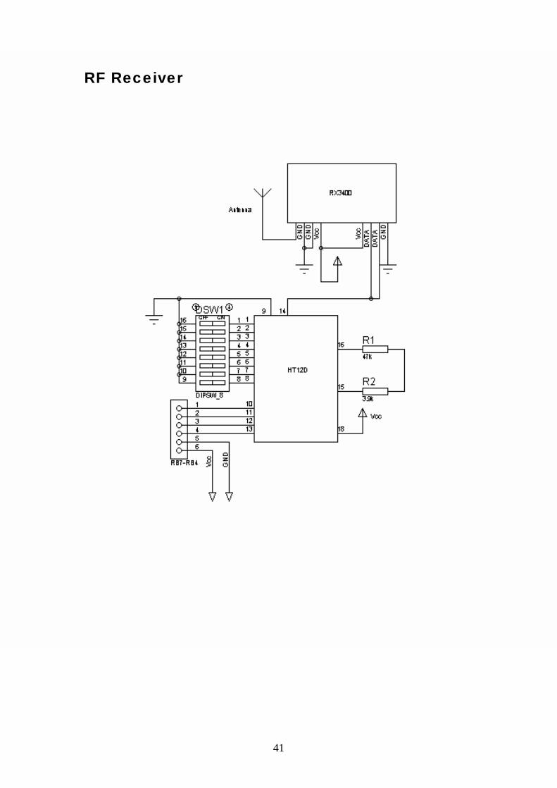
HT12D 212 series Decoder The HT12D is a decoder IC made especially to pair with the HT12E encoder. It is a CMOS IC made for remote control system applications. The decoder is capable of decoding 8 bits of address (A0-A7) and 4 bits of data (AD8-AD11) information. Like the encoder, this decoder’s address pins can be set to logic low by grounding and set to logic high by either connecting the pins to +5V or leaving them open (no connection). The decoder receives serial addresses and data from a programmed encoder transmitted by a carrier using RF or an IR transmission medium.
Four Bit Data Transmitter/Receiver Below Figure consists of a transmitter and an encoder sitting on one side for transmitting 4 bits of data, while the receiving end consists of a decoder and a receiver.
4-bit transmitter/receiver circuit In order to transmit, the data pins D0-D3 on the HT12E are set to the required logic levels and then the transmit enable (pin 14) switch is closed to enable transmission of both the 8 bit address (all zero’s in this case) and 4 bit data. The encoder outputs the 12 bit data serially using DOUT (pin 17) which goes to the 434 transmitter which transmits the encoded signal at 434 MHz. This signal is received by the 434 receiver. The serial form of received data is passed on to the decoder which checks the addresses three times with its local addresses. Upon a match, the decoder latches the exact 4 bits data on pins D0-D3 while making the valid transmission pin high. Hence a 4 bit data gets successfully transferred wirelessly using radio frequency signals.

12
Interfacing the transmitter to the parallel port The transmitter circuit is interfaced to the parallel port using optocouplers. Optoisolators/optocouplers are devices that interconnect two circuits by means of an optical interface. This means that one circuit can be used to control another circuit without undesirable changes in voltage and current that might occur if the two circuits were connected electrically. Thus electrical isolation is obtained between the parallel port and the transmitter circuit. This isolation is essential to protect the PC’s Motherboard from possible electrical damage. The figure below illustrates how the MCT2E is used to couple the LPT data outputs to the 434MHz OOK transmitter module.

13
Collision Avoidance System Need for collision avoidance Although the robot will be guided by a human operator it cannot be guaranteed that the communication will occur in real time. This is due to delays and interferences caused in the radio links. Other factors that could lead to collisions are the operator’s negligence or an unauthorized operator fiddling with the system. Enabling collision avoidance will prevent the operator from crashing the robot into obstacles such as walls thus protecting itself and also the environment. Detecting Obstacles The robot uses an infrared based system to detect obstacles. The basic principle behind our obstacle detection system is reflection. An IR sensor is used to detect the IR waves reflected from an obstacle. The output from the sensor is then used in implementing obstacle avoidance. Infrared was chosen as both sound and light are very prone to ambient interference. Another good reason to use infrared is that the relevant part of the electromagnetic spectrum is relatively quiet in an indoors environment, where we don't have to worry about heat radiated from the sun. Also the IR implementation is relatively simpler, less power hungry and much cheaper compared to ultrasonic based systems. Unfortunately for us there are many more sources of Infra-Red light. The sun is the brightest source of all, but there are many others, like: light bulbs, candles, central heating system, and even our body radiate Infra-Red light. In fact everything that radiates heat also radiates Infra-Red light. Therefore we have to take some precautions to guarantee that our obstacle detection system is not falsely triggered. The answer lies in amplitude modulating the IR waves. With modulation we make the IR light source blink in a particular frequency. The IR receiver will be tuned to that frequency, so it can ignore everything else. We chose to modulate the IR waves at 38 KHz and detect it using the TSOP1738 IR sensor.

14
Generating the 38 KHz IR wave The 38 KHz wave can be obtained by configuring a 555 timer as an Astable Oscillator.
Tlow = 0.693R2C1 Thigh = 0.693(R1+R2)C1 F = 1/( Thigh- Tlow) For reliable operation, the resistors should be between approximately 10KΩ and 14MΩ, and the timing capacitor should be from around 100pF to 1000µF. Detecting the 38 KHz IR waves The detection is done using the TSOP1738 IR sensors. These sensors are widely available and is commonly found at the receiving end of an IR remote control system; e.g., in TVs, CD players etc. The TSOP1738 has a photo detector, preamplifier and demodulator in one package. Thus no separate demodulator is required. This sensor requires the incoming data to be modulated at 38 KHz and would ignore any other IR signals. Its Epoxy coating acts as an IR filter. Thus it is highly immune to ambient IR light, so one can easily use these sensors outdoors or under heavily lit conditions.

15
Placement of sensors A TSOP1738 sensor and IR LED will be placed at the four corners of the robot platform indicated by shaded portions in the illustration shown below. Behavior of collision avoidance The behavior of the collision avoidance system is illustrated in the figure below. The robot is represented as a circle. Upon detecting the obstacle towards the left, the robot stops responding to the operator and follows a reverse curve depicted by curve CB for a short duration. On reaching point B control is restored to the operator. Curve BA represents the path along which the operator might direct the robot. The rest of the operations are best depicted in the flowchart.

16
Flowchart for collision avoidance On detecting an obstacle an interrupt is generated on PORTB RB0. This interrupt is used to prohibit the operator from controlling the robot while the microcontroller decides how to react to the obstacle. Alternatively the obstacle avoidance system can be implemented without the use of interrupts by the use of appropriate flags.

17
Limitations The obstacle avoidance system might have difficulty in detecting obstacles such as transparent glass, absolutely black objects and small or thin objects. A TV remote could falsely trigger the obstacle avoidance system. Obstacles not in level with the sensors might fail to be detected. However, tactile switches may be used to further strengthen the obstacle detection system. These limitations might restrict the use of the robot to well structured environments.

18
Locomotion
Moving is what many might call a robot‘s primary objective; it’s what separates a robot from a plain old computer sitting on the floor. A mobile robot needs locomotion mechanisms that allow it to move unbounded throughout its environment. But there are a large variety of possible ways to move, and so the selection of a robot’s approach to locomotion is an important aspect of mobile robot design. Robots can be designed to walk, jump, run, slide, skate, swim, fly and roll. Most of these locomotion mechanisms have been inspired by their biological counterparts. Biological systems succeed in moving through a wide variety of harsh environment. Therefore it can be desirable to copy their selection of locomotion mechanisms. However, replicating nature in this regard is extremely difficult. With very small size and weight, insects achieve a level of robustness that we have not been able to match with human fabrication techniques. Walking robots are highly desirable for navigating rough terrains. However, walking is actually a difficult task for any creature to perform, whether it’s human or humanoid. It takes babies nine months or longer to master the act; and for several years after that, they are targeted with the title of “toddler“. Yet, man has not been deterred and has successfully developed robots that can walk, run, hop, fly, swim and crawl. Most mobile robots are required to operate in human environments. The human environment frequently consists of engineered, smooth surfaces, both indoor and outdoors. Thus, it is understandable that virtually all industrial application of mobile robotics utilize some form of wheeled locomotion. Two common forms of locomotion are
Legged locomotion Wheeled locomotion
Legged locomotion is suited for rough terrains. However, there are complexities in achieving balance, synchronization between legs and in navigating corners. Wheeled locomotion focuses on traction, stability, maneuverability and control. All wheeled vehicles require specially prepared areas to function properly. Wheels are not usually adequate for moving across rugged terrain. A common solution is to use caterpillar tracked vehicles or a combination of legged–wheeled locomotion systems. Wheels are pretty much proven in all types of robot applications, from the smallest desktop robots to the largest mobile industrial robots. Even designers for NASA’s Mars-Exploration robots favor wheels as a mean of locomotion.

19
Types of steering Wheels are generally categorized by steering methods and mounting techniques. Single wheel drive: Here a single wheel is both driven and steered. Two passive caster wheels are required in the back for stability. For driving straight, the front wheel is positioned in the middle position and driven at the desired speed. For driving in a curve, the wheel is positioned at an angle matching the desired curve. This robot design cannot turn on the spot. With the front wheel set to 90 degrees the robot will rotate about the mid point between the two caster wheels. So the minimum turning radius is the distance between the front wheel and midpoint of the back wheels. This is illustrated in the figure below. The shaded rectangle represents the driven wheel. Ackerman steering: Ackerman steering is also known as car-type steering. A single motor source drives the wheels, and a separate motor controls the steering. This method uses two wheels in the front turning together to accomplish the turn. Sometimes a single wheel is used, as in some golf carts, or the rear wheels can turn, as in fork-lifts. This type of steering has the capacity to follow a specific path at high speeds. Its major disadvantage is its inability to “turn on a dime”, or spin about its axis. Its turning radius is limited by the front–rear wheel separation and angle that the front wheels can turn.

20
Differential steering: Differential steering, sometimes called “tank type” steering, is not to be confused with tank treads. The similarity is in the way an operator can separately control the speeds of the left and right wheels to cause a directional change in the motion of the robot. Two separately driven side wheels have its own motor, and no motor is required to turn any wheel to steer. Spinning on the robots axis is accomplished by moving one wheel in one direction and the other in opposite direction. A sharp turn is accomplished by stopping one wheel while moving the other forward or backward, and the result is a turn about the axis of stopped wheel. Shallower turns are accomplished by moving one wheel at a slower speed than the other wheel, making the robot turn in the direction of the slower wheel. The wheels versus threads controversy has produced a design variation that does not use the free moving casters, but instead uses a series of side-mounted wheels, similar to the idlers pressing downward on the inside of tank treads. Each set of wheels on either side is interconnected by a single chain or belt drive and a single motor per side. The paraBOT also makes use of this design wherein the front wheels (on each side) are independently linked to the rear wheels. This method provides more traction but hogs more battery power due to increased friction.

21
Drive system of the paraBOT PWM Motor Control In order to achieve speed control of the DC motors the two hardware PWM modules of the PIC16F877A are used. The PWM signals are fed to the enable lines of the L293D motor driver. By varying the PWM pulse width across its full range, from absolute minimum to absolute maximum, the motor speed can be continuously varied. The direction of the motor is decided by the IN lines of the L293D.

22
Conclusions Summary of achievements
A GUI was designed in Visual Basic 6 and tested for outputs at the parallel port.
The 434 MHz transmitter was interfaced to the parallel port and the receiver successfully received the signals beyond 10m even through the lab walls.
PWM motor control was tested with the L293D using a function generator. Obstacle Detection was tested using the TSOP1738 IR sensors up to a distance
of 1 Ft. An ICSP circuit recognized by the PICPgm programmer was tested with
PIC16F873A, PIC16F877 and PIC16F877A microcontrollers. PWM generation was tested using the PIC16F877 and PIC16F877A Code to control the robot was written in mikroC and was tested with the
PIC16F877 and PIC16F877A Two separate codes, one using interrupts and the other without using interrupts
were written. Both gave optimum performances with no indicative time differences. It was decided to use the code without interrupts as it used less code memory.

23
Suggestions for future work A full duplex RF communication link could be implemented. This would allow interfacing a pan-tilt camera to provide visual feedback to the operator. The robot could then be operated in remote environments. A solar panel could be used to provide power when the robot is operated outdoors. An auto-switching feature could be implemented to choose power sources depending on the environment. Levels of artificial intelligence and genetic behaviors such as wall following, maze solving, ant behaviors, path finding, fire fighting, etc. could be implemented. Various tools such as arms, grippers, pumps, etc. can be used to provide added functionality. The obstacle avoidance system could be greatly improved by using ultrasonic sensors or even image processing.

24
Applications With sufficient modifications the robot can be used for
Surveillance Bomb disposal Fire fighting Spying Remote assistance Site monitoring or exploration Search operations Pipe and air-duct inspection Nuclear waste handling Toys
The obstacle avoidance system could be used in auto-parking and accident prevention systems. It could also be used to assist in guiding visually impaired people.

25
Appendix A – The Parallel Port The primary use of parallel port is to connect printers to computer and is specifically designed for this purpose. Thus it is often called as printer Port or Centronics port (this name came from a popular printer manufacturing company 'Centronics' who devised some standards for parallel port). You can see the parallel port connector in the rear panel of your PC. It is a 25 pin female (DB25) connector (to which printer is connected). On almost all the PCs only one parallel port is present, but you can add more by buying and inserting ISA/PCI parallel port cards. The Parallel port can function as a simple and inexpensive tool for building computer controlled devices and projects. The simplicity and ease of programming makes the port popular in an electronics hobbyist world. The parallel port is often used in computer controlled robots, Atmel/PIC programmers, home automation, etc. Parallel port modes The IEEE 1284 Standard which has been published in 1994 defines five modes of data transfer for parallel port. They are:
1. Compatibility Mode 2. Nibble Mode 3. Byte Mode 4. EPP (Enhanced Parallel Port). 5. ECP (Extended Capabilities Port).
Compatibility mode or "Centronics Mode" as it is commonly known, can only send data in the forward direction at a typical speed of 50 kbytes per second but can be as high as 150+ kbytes a second. In order to receive data, you must change the mode to either Nibble or Byte mode. Nibble mode can input a nibble (4 bits) in the reverse direction. e.g. from device to computer. Byte mode uses the bi-directional feature (found only on some cards) to input a byte (8 bits) of data in the reverse direction. Extended and Enhanced Parallel Ports use additional hardware to generate and manage handshaking.

26
Hardware The pin outs of DB25 connector is shown in the picture below: The lines in DB25 connector are divided into three groups, they are:
1. Data lines (data bus) 2. Control lines 3. Status lines
As the name refers, data is transferred over data lines. Control lines are used to control the peripheral, and of course, the peripheral returns status signals back to the computer through Status lines. These lines are connected to Data, Control and Status registers internally. The details of parallel port signal lines are given below:
Pin No (DB25)
Signal name Direction Register
- bit Inverted
1 nStrobe Out Control-0 Yes
2 Data0 In/Out Data-0 No 3 Data1 In/Out Data-1 No 4 Data2 In/Out Data-2 No 5 Data3 In/Out Data-3 No 6 Data4 In/Out Data-4 No 7 Data5 In/Out Data-5 No 8 Data6 In/Out Data-6 No 9 Data7 In/Out Data-7 No 10 nAck In Status-6 No 11 Busy In Status-7 Yes
12 Paper-Out In Status-5 No
13 Select In Status-4 No
14 Linefeed Out Control-1 Yes
15 nError In Status-3 No
16 nInitialize Out Control-2 No
17 nSelect-Printer Out Control-
3 Yes
18-25 Ground - - -

27
Parallel port registers The Data, Control and Status lines are connected to their corresponding registers inside the computer. So, by manipulating these registers in a program, one can easily read or write to the parallel port with programming languages such as C and BASIC. The registers found in a standard parallel port are:
1. Data register 2. Status register 3. Control register
As their names specify, Data register is connected to Data lines, Control register is connected to Control lines and Status register is connected to Status lines. So, whatever you write to these registers will appear in the corresponding lines as voltages. Where are these registers? In an IBM PC, these registers are IO mapped and will have a unique address. We have to find these addresses to work with the parallel port. For a typical PC, the base address of LPT1 is 0x378 and of LPT2 is 0x278. The Data register resides at this base address, Status register at base address + 1 and the control register is at base address + 2. So, once we have the base address, we can calculate the address of each register in this manner. The table below shows the register addresses of LPT1 and LPT2.
Register LPT1 LPT2 Data register (base address + 0) 0x378 0x278 Status register (base address + 1) 0x379 0x279 Control register (base address + 2) 0x37a 0x27a
On modern Windows systems you can get to know the parallel port I/O address through device manager. The address is found in the resources tab of the printer port properties accessible in the Ports (COM & LPT) section.

28
Another way to find the Parallel Port Address is through the BIOS. Some other names for the Parallel Port are
Printer Port Centronics Port LPT (Line Print Terminal)

29
Appendix-B Source Code Mobile Robot C code for PIC16F877A using interrupts /* PORTC.F[3-6] --> control motor direction PORTC.F1 ------> PWM2 for right motor PORTC.F2 ------> PWM1 for left motor PORTB.F[7-4]---> manual control codes (RB7-4 port change interrupts) PORTD.F[3-0]---> obstacle detection PORTB.F0 ------>RB0/INT interrupt if obstacle is detected; ParaBOT test code for 28th March 2008 */ ///////////////////////////////////////////////////////////////////// int Ob_flag = 1; //flag to disable/enable obstacle avoidance int PWM_flag = 1; //flag to set speed of motors int count = 0; int i; void forward(); void reverse(); void stop(); void fwdLeft(); void fwdRight(); void revLeft(); void revRight(); void left(); void right(); void manual(); void obstacle(); ///////////////////////////////////////////////////////////////////// void main() //Main function for initialisation { Pwm_Init(1500); PORTB = 255; TRISB = 249; PORTC = 0; TRISC = 0; OPTION_REG.INTEDG = 1; INTCON.GIE = 1; INTCON.RBIE = 1; while(1) { //do nothing; Operator might be busy or sleeping } } ///////////////////////////////////////////////////////////////////// ////*** Check if operator has control or Obstacle is detected ***//// void interrupt() { if( INTCON.RBIF == 1) //check for manual control { INTCON.RBIE = 0; INTCON.RBIF = 0; INTCON.INTF = 0; manual(); INTCON.RBIE = 1; } else if(INTCON.INTF == 1) //check for obstacles

30
{ INTCON.INTF = 0; if(Ob_flag == 0) INTCON.INTE = 1; else INTCON.INTE = 0; obstacle(); } } ///////////////////////////////////////////////////////////////////// ////*** Manual operator control routine ***//// void manual() //function for manual operation { if((PORTB&0xF0)==16) //forward forward(); else if((PORTB&0xF0)== 32) //reverse reverse(); else if((PORTB&0xF0)== 48) //toggle horn { PORTB.F1 = 0; delay_ms(500); PORTB.F1 = 1; } else if((PORTB&0xF0)== 64) //sharp left left(); else if((PORTB&0xF0)== 80) //gradual forward left fwdLeft(); else if((PORTB&0xF0)== 96) //gradual reverse left revLeft(); else if((PORTB&0xF0)== 112) //Slower speed (PWM max duty = 80%) PWM_flag = 0; else if((PORTB&0xF0)== 128) //sharp right right(); else if((PORTB&0xF0)== 144) //gradual forward right fwdRight(); else if((PORTB&0xF0)== 160) //gradual reverse right revRight(); else if((PORTB&0xF0)== 176) //high speed (PWM max duty = 100%) PWM_flag = 1; else if((PORTB&0xF0) == 192) //enable obstacle avoidance { INTCON.INTE = 1; Ob_flag = 0; } else if((PORTB&0xF0) == 208) //disable obstacle avoidance { INTCON.INTE = 0; INTCON.INTF = 0; Ob_flag = 1; } else //stop stop(); } ///////////////////////////////////////////////////////////////////// ////*** Routine to get out of an obstacle trap ***//// void obstacle() { if((PORTD&0x0F)== 3) //Obstacle behind { INTCON.RBIE = 0;

31
forward(); } else if((PORTD&0x0F)== 7) //Obstacle behind towards left { INTCON.RBIE = 0; fwdLeft(); } else if((PORTD&0x0F)== 11) //Obstacle behind towards right { INTCON.RBIE = 0; fwdRight(); } else if((PORTD&0x0F)== 12) //Obstacle in front { INTCON.RBIE = 0; reverse(); } else if((PORTD&0x0F)== 13) //Obstacle in front towards right { INTCON.RBIE = 0; revRight(); } else if((PORTD&0x0F)== 14) //Obstacle in front towards left { INTCON.RBIE = 0; revLeft(); } else { INTCON.RBIE = 0; //Obstacle blocking both front and behind right(); //if obstacle on all sides then stop for 5 counts //and allow the operator to control the robot for(i=0; i<=2;i++) { PORTB.F1 = 0; delay_ms(200); PORTB.F1 = 1; INTCON.RBIE = 1; delay_ms(200); } if(Ob_flag == 0) //check if the operator disabled obstacle avoidance INTCON.INTE = 1; else INTCON.INTE = 0; } Delay_ms(500); stop(); INTCON.RBIE = 1; } ///////////////////////////////////////////////////////////////////// ///////////////////////////////////////////////////////////////////// ////*** Motor Control Routines ***//// void forward() //function for forward motion { if(PWM_flag == 1) { Pwm1_Change_Duty(255); Pwm2_Change_Duty(255);

32
} else { Pwm1_Change_Duty(204); Pwm2_Change_Duty(204); } Pwm1_Start(); Pwm2_Start(); PORTC.F3 = 1; PORTC.F4 = 0; PORTC.F5 = 1; PORTC.F6 = 0; } void reverse() //function for reverse motion { if(PWM_flag == 1) { Pwm1_Change_Duty(255); Pwm2_Change_Duty(255); } else { Pwm1_Change_Duty(204); Pwm2_Change_Duty(204); } Pwm1_Start(); Pwm2_Start(); PORTC.F3 = 0; PORTC.F4 = 1; PORTC.F5 = 0; PORTC.F6 = 1; } void stop() //function to stop { Pwm1_Stop(); Pwm2_Stop(); PORTC.F3 = 0; PORTC.F4 = 0; PORTC.F5 = 0; PORTC.F6 = 0; PORTC.F1 = 0; PORTC.F2 = 0; } void fwdLeft() //function for forward-left turning { if(PWM_flag == 1) { Pwm1_Change_Duty(204); Pwm2_Change_Duty(255); } else { Pwm1_Change_Duty(153); Pwm2_Change_Duty(204); } Pwm1_Start(); Pwm2_Start();

33
PORTC.F3 = 1; PORTC.F4 = 0; PORTC.F5 = 1; PORTC.F6 = 0; } void fwdRight() //function for forward-right turning { if(PWM_flag == 1) { Pwm1_Change_Duty(255); Pwm2_Change_Duty(204); } else { Pwm1_Change_Duty(204); Pwm2_Change_Duty(153); } Pwm1_Start(); Pwm2_Start(); PORTC.F3 = 1; PORTC.F4 = 0; PORTC.F5 = 1; PORTC.F6 = 0; } void revLeft() //function for reverse-left turning { if(PWM_flag == 1) { Pwm1_Change_Duty(204); Pwm2_Change_Duty(255); } else { Pwm1_Change_Duty(153); Pwm2_Change_Duty(204); } Pwm1_Start(); Pwm2_Start(); PORTC.F3 = 0; PORTC.F4 = 1; PORTC.F5 = 0; PORTC.F6 = 1; } void revRight() //function for reverse-right turning { if(PWM_flag == 1) { Pwm1_Change_Duty(255); Pwm2_Change_Duty(204); } else { Pwm1_Change_Duty(204); Pwm2_Change_Duty(153); } Pwm1_Start(); Pwm2_Start();

34
PORTC.F3 = 0; PORTC.F4 = 1; PORTC.F5 = 0; PORTC.F6 = 1; } void left() //function for sharp left turning { if(PWM_flag == 1) { Pwm1_Change_Duty(255); Pwm2_Change_Duty(255); } else { Pwm1_Change_Duty(204); Pwm2_Change_Duty(204); } Pwm1_Start(); Pwm2_Start(); PORTC.F3 = 0; PORTC.F4 = 1; PORTC.F5 = 1; PORTC.F6 = 0; } void right() //function for sharp right turning { if(PWM_flag == 1) { Pwm1_Change_Duty(255); Pwm2_Change_Duty(255); } else { Pwm1_Change_Duty(204); Pwm2_Change_Duty(204); } Pwm1_Start(); Pwm2_Start(); PORTC.F3 = 1; PORTC.F4 = 0; PORTC.F5 = 0; PORTC.F6 = 1; } ///////////////////////////////////////////////////////////////////// ////////////////////////////END OF PROGRAM///////////////////////////

35
Mobile Robot C code for PIC16F877A without interrupts int i; int count = 0; int countb = 0; short int PWM_flag = 1; //PWM_flag --->flag to set speed of motors void forward(); void reverse(); void stop(); void fwdLeft(); void fwdRight(); void revLeft(); void revRight(); void left(); void right(); void manual(); void obstacle(); ////////////////////////////Main function//////////////////////////// void main() { Pwm_Init(2000); PORTB = 255; TRISB = 249; PORTC = 0; TRISC = 0; PORTD = 255; TRISD = 255; while(1) { while(PORTD!=15) { obstacle(); count++; if(count == 15) { Pwm1_stop(); Pwm2_stop(); break; } } manual(); count = 0; } } ////////////////*** Manual operator control routine ***////////////// void manual() { if((PORTB&0xF0)==16) //forward forward(); else if((PORTB&0xF0)== 32) //reverse reverse(); else if((PORTB&0xF0)== 48) //toggle horn { PORTB.F1 = 0; delay_ms(250); PORTB.F1 = 1; } else if((PORTB&0xF0)== 64) //sharp left left(); else if((PORTB&0xF0)== 80) //gradual forward left fwdLeft();

36
else if((PORTB&0xF0)== 96) //gradual reverse left revLeft(); else if((PORTB&0xF0)== 112) //Slower speed (PWM max duty = 80%) PWM_flag = 0; else if((PORTB&0xF0)== 128) //sharp right right(); else if((PORTB&0xF0)== 144) //gradual forward right fwdRight(); else if((PORTB&0xF0)== 160) //gradual reverse right revRight(); else if((PORTB&0xF0)== 176) //high speed (PWM max duty = 100%) PWM_flag = 1; else //stop stop(); } /////////////////////////end of manual control/////////////////////// //////////////////*** obstacle avoidance routine ***///////////////// void obstacle() { if((PORTD&0x0F)== 3) //Obstacle behind { forward(); } else if((PORTD&0x0F)== 7) //Obstacle behind towards left { fwdLeft(); } else if((PORTD&0x0F)== 11) //Obstacle behind towards right { fwdRight(); } else if((PORTD&0x0F)== 12) //Obstacle in front { reverse(); } else if((PORTD&0x0F)== 13) //Obstacle in front towards right { revRight(); } else if((PORTD&0x0F)== 14) //Obstacle in front towards left { revLeft(); } else //Obstacle blocking both front and behind { right(); countb++; for(i=0;i<=7;i++) { PORTB.F1 = ~PORTB.F1;; delay_ms(250); if((i==2)||(i==6)) { PORTB.F1 = 0; delay_ms(800); } } if(countb == 20) { stop();

37
for(i=0;i<=99000;i++) manual(); countb = 0; } } } //////////////////////end of obstacle avoidance////////////////////// /////////////////////*** Motor Control Routines ***////////////////// void forward() //function for forward motion { if(PWM_flag == 1) { Pwm1_Change_Duty(255); Pwm2_Change_Duty(255); } else { Pwm1_Change_Duty(178); Pwm2_Change_Duty(178); } Pwm1_Start(); Pwm2_Start(); PORTC.F3 = 1; PORTC.F4 = 0; PORTC.F5 = 1; PORTC.F6 = 0; } void reverse() //function for reverse motion { if(PWM_flag == 1) { Pwm1_Change_Duty(255); Pwm2_Change_Duty(255); } else { Pwm1_Change_Duty(178); Pwm2_Change_Duty(178); } Pwm1_Start(); Pwm2_Start(); PORTC.F3 = 0; PORTC.F4 = 1; PORTC.F5 = 0; PORTC.F6 = 1; } void stop() //function to stop { Pwm1_Stop(); Pwm2_Stop(); PORTC.F3 = 0; PORTC.F4 = 0; PORTC.F5 = 0; PORTC.F6 = 0; PORTC.F1 = 0; PORTC.F2 = 0; }

38
void fwdLeft() //function for forward-left turning { if(PWM_flag == 1) { Pwm1_Change_Duty(178); Pwm2_Change_Duty(255); } else { Pwm1_Change_Duty(127); Pwm2_Change_Duty(178); } Pwm1_Start(); Pwm2_Start(); PORTC.F3 = 1; PORTC.F4 = 0; PORTC.F5 = 1; PORTC.F6 = 0; } void fwdRight() //function for forward-right turning { if(PWM_flag == 1) { Pwm1_Change_Duty(255); Pwm2_Change_Duty(178); } else { Pwm1_Change_Duty(178); Pwm2_Change_Duty(127); } Pwm1_Start(); Pwm2_Start(); PORTC.F3 = 1; PORTC.F4 = 0; PORTC.F5 = 1; PORTC.F6 = 0; } void revLeft() //function for reverse-left turning { if(PWM_flag == 1) { Pwm1_Change_Duty(178); Pwm2_Change_Duty(255); } else { Pwm1_Change_Duty(127); Pwm2_Change_Duty(178); } Pwm1_Start(); Pwm2_Start(); PORTC.F3 = 0; PORTC.F4 = 1; PORTC.F5 = 0; PORTC.F6 = 1; } void revRight() //function for reverse-right turning

39
{ if(PWM_flag == 1) { Pwm1_Change_Duty(255); Pwm2_Change_Duty(178); } else { Pwm1_Change_Duty(178); Pwm2_Change_Duty(127); } Pwm1_Start(); Pwm2_Start(); PORTC.F3 = 0; PORTC.F4 = 1; PORTC.F5 = 0; PORTC.F6 = 1; } void left() //function for sharp left turning { if(PWM_flag == 1) { Pwm1_Change_Duty(255); Pwm2_Change_Duty(255); } else { Pwm1_Change_Duty(178); Pwm2_Change_Duty(178); } Pwm1_Start(); Pwm2_Start(); PORTC.F3 = 0; PORTC.F4 = 1; PORTC.F5 = 1; PORTC.F6 = 0; } void right() //function for sharp right turning { if(PWM_flag == 1) { Pwm1_Change_Duty(255); Pwm2_Change_Duty(255); } else { Pwm1_Change_Duty(178); Pwm2_Change_Duty(178); } Pwm1_Start(); Pwm2_Start(); PORTC.F3 = 1; PORTC.F4 = 0; PORTC.F5 = 0; PORTC.F6 = 1; } ///////////////////////end of motor control routines///////////////// ////////////////////////////END OF PROGRAM///////////////////////////

40
Appendix C – Complete Schematics RF Transmitter
41
RF Receiver

42
Main board

43
Obstacle Detector

44
Appendix D – PCB Designs Transmitter (top-view) Transmitter (bottom-view) Receiver (top-view) Receiver (bottom-view)
Obstacle detector (top-view)

45
Main board (top-view) Main board (bottom-view)

46
Appendix E – Datasheets Receiver Crystal tuned PLL based ASK module
Pin Details
Pin No. Purpose Description Notes 1 Ant Antenna Whip Antenna
22.6cm: 315Mhz 17.2cm: 434Mhz
2 Gnd Ground 0 volts 3 Gnd Ground 0 volts 4 Vcc Positive of power supply 3v – 12v 5 Vcc Positive of power supply 3v – 12v 6 Data Digital data output 1k – 10kbps 7 Data Digital data output 1k – 10kbps 8 Gnd Ground 0 volts
315/433 MHz ASK Module
47
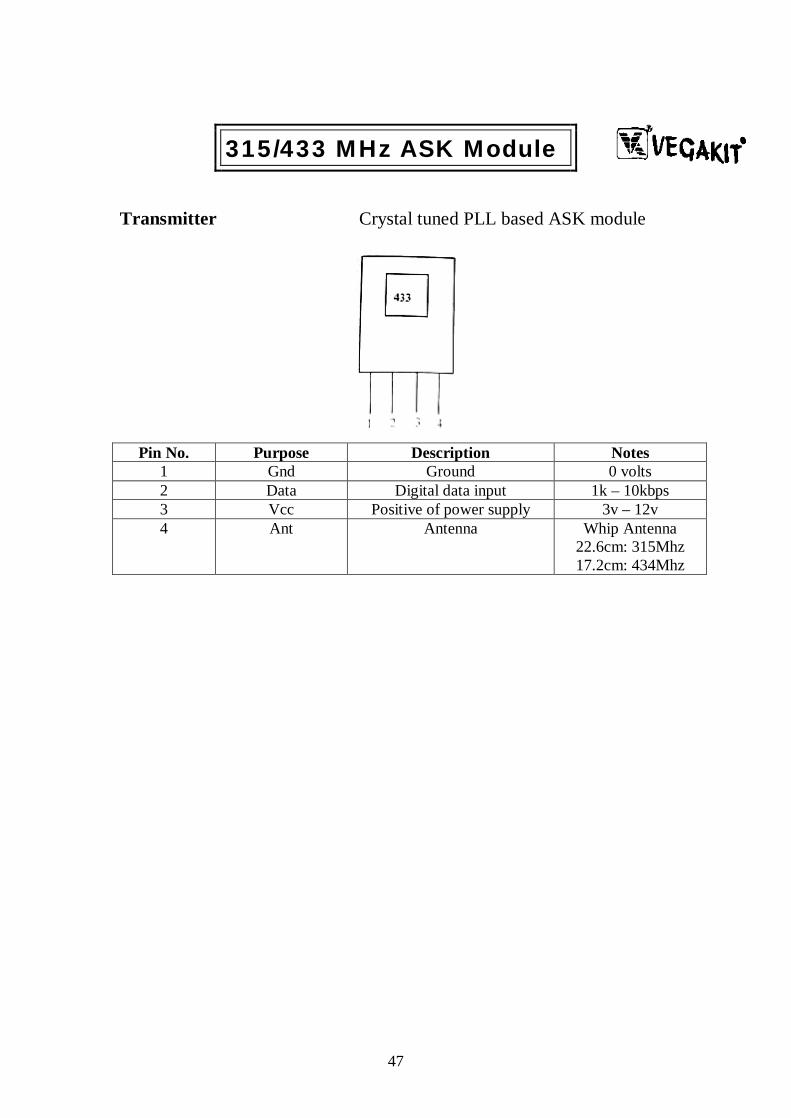
Transmitter Crystal tuned PLL based ASK module
315/433 MHz ASK Module
Pin No. Purpose Description Notes 1 Gnd Ground 0 volts 2 Data Digital data input 1k – 10kbps 3 Vcc Positive of power supply 3v – 12v 4 Ant Antenna Whip Antenna
22.6cm: 315Mhz 17.2cm: 434Mhz


52
Appendix F - Parts Listing and Prices Description Quantity Rate Amount in Rupees MC2TE 6 10 60 NE555 15 4 60 TSOP1738 5 45 255 IR LED 5 2 10 10 MHz Crystal 1 5 5 20 MHz Crystal 1 5 5 PIC16F873A 1 115 115 PIC16F84A 1 85 85 PIC16F877A 1 250 250 L293D 1 75 75 28 pin ZIF socket 2 50 100 HT12E/12D 1 pair 50 50 RF 433 MHz module
1 363 363
Most of the components were bought from GALA ELECTRONICS, Mumbai
53
Bibliography Robotics References Build your own combat robots Pete Miles & Tom Carroll Introduction to autonomous mobile robots Roland Siegwart & Illah R. Nourbakhsh Embedded Robotics – Mobile robot design and applications with embedded systems Thomas Braunl Robotics – Mechanical Engineering Handbook Frank Kreith The Robot Builders Bonanza Gordon McComb & Myke Predko Robot mechanisms and mechanical devices Paul E. Sandin
Parallel Port References Programming the parallel port Dhananjay V. Gadre Parallel port complete Jan Axelson
Visual Basic 6 References Programming in Visual Basic 6.0 Julia Case Bradley & Anita C. Millspaugh Visual Basic for Electronics Engineering Applications – Second Edition Vincent Himpe Visual Basic 6 Complete Visual Basic 6 Black Book Steven Holzner

54
PICmicro References Designing Embedded Systems with PIC Microcontrollers – Principles and Applications Tim Wilmshurst Microcontroller Programming – The Microchip PIC Julio Sanchez & Maria P. Canton PIC C – An introduction to programming the Microchip PIC in C Nigel Gardner PICmicro™ Mid-Range MCU Family Reference Manual
Online references www.google.com www.yahoo.com www.roboticsindia.com www.seattlerobotics.org www.triindia.co.in www.endtas.com www.rentron.com www.logix4u.net www.bitwisemag.com www.thaiio.com www.developerfusion.co.uk www.devx.com www.pololu.com www.microchip.com www.microchipc.com www.dprg.org