this manual describes items related to the construction of
TRANSCRIPT


This manual describes items related to the construction of a network that employs
CC-Link IE controller network compatible products, including the matters to be studied in
advance, onsite cable installation work check items, and cable installation precautions.
We hope that you will utilize this manual to ensure smooth construction of a CC-Link IE
controller network.

Table of Contents
Chapter 1 NETWORK CABLE INSTALLATION PROCEDURE .................................... 1 Chapter 2 NETWORK SPECIFICATIONS..................................................................... 2 Chapter 3 SELECTING THE CONNECED DEVICES................................................... 3
3.1 Fiber Optic Cable ..................................................................................................... 3 3.2 Optical Connector .................................................................................................... 4
Chapter 4 CALCULATING AND CHECKING THE TRANSMISSION LOSS VALUE .... 5 4.1 Calculating the Transmission loss Value ................................................................. 5 4.2 Transmission loss Measurement Method................................................................ 6
Chapter 5 PRECAUTIONS ............................................................................................ 8 5.1 Installing the Cable .................................................................................................. 8 5.2 Fusion Splicing and Adapter Splicing..................................................................... 10

1
Chapter 1 NETWORK CABLE INSTALLATION PROCEDURE
The following describes the CC-Link IE controller network cable installation procedure.
Transmission path designFusion splicing or splicing byadaptorSelection of fiber optic cableCalculation of transmission loss
Are CC-Link IEcontroller network
specifications satisfied?
Preparation of devices
Cable installation and check
Is the transmission loss valueless than or equal to therecommender value ?
Transmission loss measurement
Yes
Yes
No
No
Figure 1 Cable Installation Procedure

2
Chapter 2 NETWORK SPECIFICATIONS
The CC-Link IE controller network is an Ethernet-based loop topology network that
employs IEEE802.3 1000Base-SX technology in its physical layer and data link layer.
Table 1 describes the communication specifications related to CC-Link IE controller
network cable laying.
Table 1 Communication Specifications
Item Specification
Communication speed 1Gbps
No. of connected nodes per network 120 nodes (1 control node, 119 normal nodes)
Type of cable Fiber optic cable (multimode fiber)
Total cable length 66,000m (with 120 nodes connected)
Maximum distance between nodes 550m
Maximum number of networks 239
Topology Dual loop
IEEE802.3 1000Base-SX (MMF) compatible fiber
optic cable
Standard IEC60793-2-10 Types A1a.1 (50/125μm multimode)
Transmission loss (max) 3.5 dB/km or less [λ=850nm]
Fiber optic
cable
specifications
Transmission band (min) 500 MHz/km or greater [λ=850nm]
Duplex LC Connector (LCF connector)
Standard IEC61754-20: Type LC connector
Insertion loss 0.3 dB or less
Connector
specifications
Polishing method PC polishing
3
Chapter 3 SELECTING THE CONNECED DEVICES
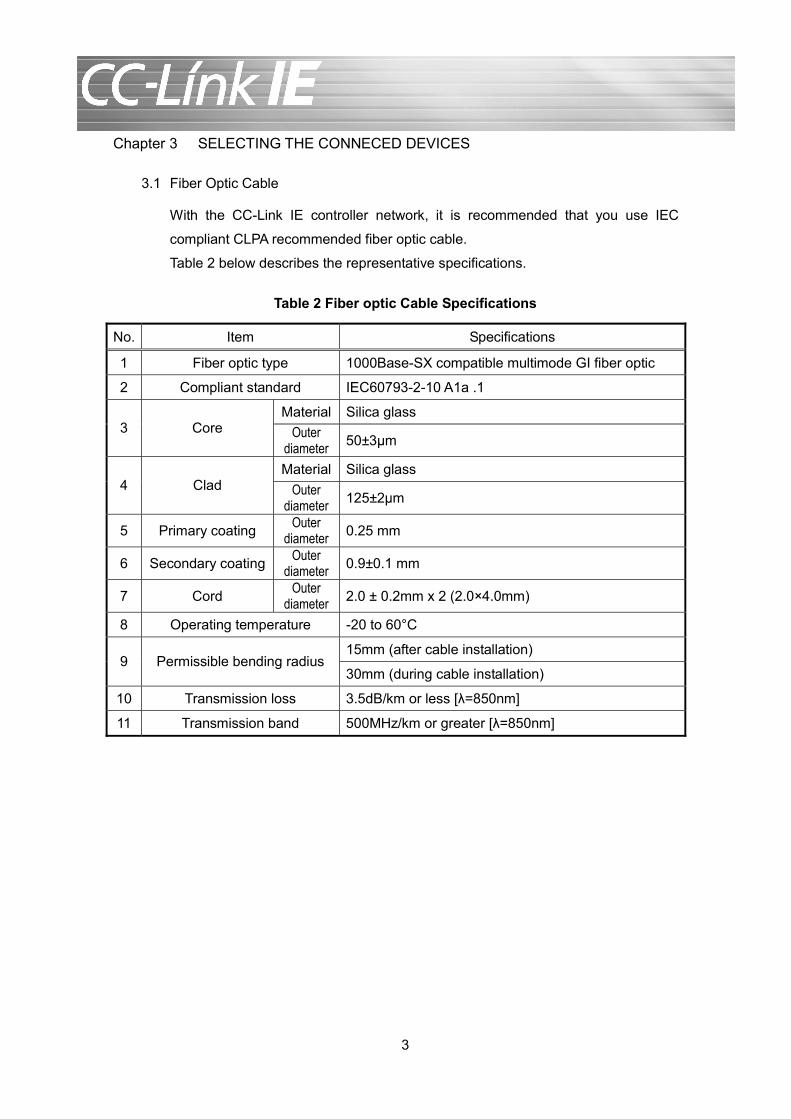
3.1 Fiber Optic Cable
With the CC-Link IE controller network, it is recommended that you use IEC
compliant CLPA recommended fiber optic cable.
Table 2 below describes the representative specifications.
Table 2 Fiber optic Cable Specifications
No. Item Specifications
1 Fiber optic type 1000Base-SX compatible multimode GI fiber optic
2 Compliant standard IEC60793-2-10 A1a .1
Material Silica glass 3 Core Outer
diameter 50±3μm
Material Silica glass 4 Clad Outer
diameter 125±2μm
5 Primary coating Outer diameter 0.25 mm
6 Secondary coating Outer diameter 0.9±0.1 mm
7 Cord Outer diameter 2.0 ± 0.2mm x 2 (2.0×4.0mm)
8 Operating temperature -20 to 60°C
15mm (after cable installation) 9 Permissible bending radius
30mm (during cable installation)
10 Transmission loss 3.5dB/km or less [λ=850nm]
11 Transmission band 500MHz/km or greater [λ=850nm]
4
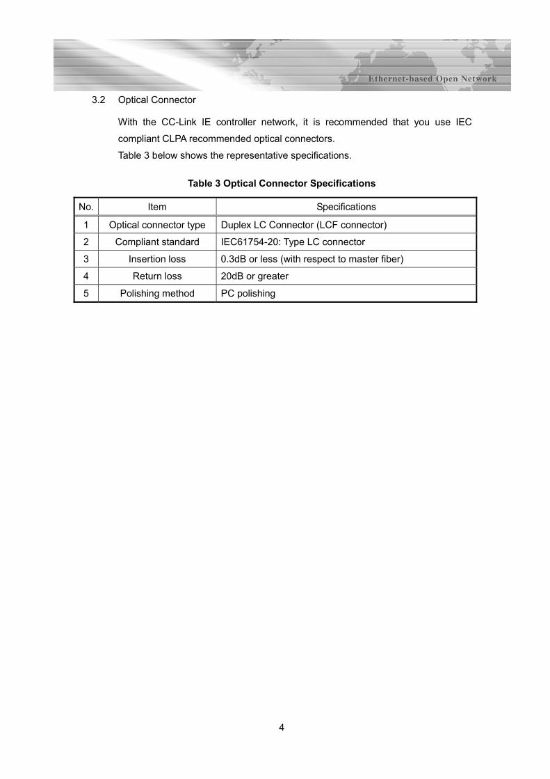
3.2 Optical Connector
With the CC-Link IE controller network, it is recommended that you use IEC
compliant CLPA recommended optical connectors.
Table 3 below shows the representative specifications.
Table 3 Optical Connector Specifications
No. Item Specifications
1 Optical connector type Duplex LC Connector (LCF connector)
2 Compliant standard IEC61754-20: Type LC connector
3 Insertion loss 0.3dB or less (with respect to master fiber)
4 Return loss 20dB or greater
5 Polishing method PC polishing

5
Chapter 4 CALCULATING AND CHECKING THE TRANSMISSION LOSS VALUE
During optical cable installation, confirm that the transmission loss between nodes is less
than or equal to the recommended transmission loss value.
4.1 Calculating the Transmission loss Value
Calculate the transmission loss value using the calculation formula below, and
confirm that the value is less than or equal to the recommended transmission loss
value (4.5dB).
Transmission loss value (dB) = Fiber optic transmission loss standard value
(dB/km) x Fiber optic cable length (km) ······························[1]
+ Fusion splicing loss value (dB/location) x Number of
fusion splicing (locations) ····················································[2]
+ Adapter splicing loss value (dB/location) x Number of
adapter splicing (locations) ·················································[3]
[1] Fiber optic cable transmission loss standard value (dB/km): According to Fiber
Optic Cable Specification
[2] Fusion splicing loss value (dB/location): 0.2dB or less/location
[3] Connector adapter splicing loss value (dB/location): According to optical
connector type and manufacturer
Transmission loss value (dB) ≤ 4.5 (dB) …CLPA recommended value
[Calculation example]
Conditions:
GI fiber optic (transmission loss value: 3.5dB/km) Total cable length of 550m
Table 4 Examples of Connector Adapter Splicing Loss Value
Fiber Optic Type Connector Type
No. of
Cores
Polishing
Method SM (dB or less) GI (dB or less) Remarks
SC 0.7 0.4
LC Single-core PC polishing
0.5 0.3
Reference
value
Note: The values above differ according to manufacturer.
For details, check with the adapter manufacturer.

6
Fusion splice connection
LC SC SC SC SC2LC LC LC
Termination box 1 Termination box 2 Termination box 3
Station addition planned
[1] Cable
transmission loss
[2] Fusion splice
connection loss
[3] Connector adapter
connection loss
Transmission
loss value (dB)
= (3.5dB/km×0.55 km) + (0.2db x 2 locations)+ (0.4dB x 2 locations + 0.3 db x
1 location)
= 3.425(dB)
4.2 Transmission loss Measurement Method
Measure the transmission loss between nodes following the procedure below, and
confirm that the measured value is less than or equal to the transmission loss
value calculated in Section 4.1.
(1) Measuring the optical input Pin (Standard outgoing beam: Measured cable
incoming beam)
[1] Connect an exciter.
Optical source Power meter
Optical sensor
Exciter Pin measurement
Wavelength: 850nm
[2] Set the mode to dBm mode and measure Pin [dBm].
Fusion splicing

7
(2) Measuring the optical output Pout (measured cable outgoing beam)
[1] Connect the relay adapter and optical fiber cable to be measured to the
exciter.
Optical sensor
Exciter
Relay adapter
Fiber optic cable to be measured *1
Pout measurementPower meter
IN side OUT side
Optical source
Wavelength: 850nm
*1 Including all adapter splicing locations and fusion splicing locations
(including all splicing locations between nodes).
[2] Measure Pout (dBM) in dBm mode.
(3) Transmission loss value Px [dB]
P x [dB] = Pin [dBm] - Pout [dBm] - Pc [dB] (Adapter splicing loss when
connected with exciter)
(4) Since the CC-Link IE controller network uses a two-core optical fiber cable,
measure the second fiber optic core in the same manner.

8
Chapter 5 PRECAUTIONS
5.1 Installing the Cable
During fiber optic cable installation, be sure to follow the following precautions.
Cable path
• Use a pit or cable rack for the cable routing as far as possible.
• When using conduit, ensure that the inner diameter of the conduit is large
enough to accommodate the dimensions of the cable connector. When
providing a pull box in the conduit, select a box that satisfies the cable’s
permissible bending radius.
• Use a dedicated cable routing path as far as possible. When sharing the
path with other cables, lay the fiber optic cable last.
• Use a path into which water or oil cannot enter, and which will not reach
temperatures higher or lower than the applicable temperature
specifications of the cable.
Pipe path
• Install the cable without directly pulling the cable. Instead, fix the cable
onto a pulling rope or the like. Depending on the cable specification,
cables that can be directly pulled also exist. Check with the manufacturer.
Precautions for cable pulling
• Pull the cable from the leading end at a pulling speed of 10m/min or less.
Make sure that the tension applied to the cable is even, and pull the cable
at a tension half or less than the permissible tension.
• Establish a bending radius during pulling that is at least two times the
minimum permissible bending radius or higher.
• Take care that the cable does not become entangled during installation.
Particularly, certain hanger rollers are structured in such a way that
readily causes entanglement. When installing lengthy cables, it is
recommended that you use a wire wheel.
• Make sure that kinks are not created in the cable.
Protection with respect to permissible tension
• When installing the cables vertically or when using aerial installation,
support the cable so that the tension caused by its own weight does not
exceed the permissible tension.

9
Prevention of moisture permeation
• In general, the optical fiber itself has poor water resistance. Permeation of
water from the optical cable ends may have adverse effects in the long
term. Additionally, there have been cases where the condensation that
arises due to temperature gradients within the laid optical cable route
permeates the optical cable, resulting in adverse effects. When installing
the optical cable, be sure to make the optical cable ends waterproof.
Protection of connector section
• Protect the connector section with a vinyl hose, pulling eye, or the like
when laying the cable. Do not pull the connector section. The connector
section is especially sensitive to impact and tension.
Other
• Seal both ends of the cable at a time other than when installing the cable
to prevent water seepage.
• The ends of the fiber optic cable are sharp. Be careful during handling.
• Do not touch or bump the end of the optical connector.

10
5.2 Fusion Splicing and Adapter Splicing
The length of the optical fiber cable can be extended by using a fusion splice or
relay adapter. When making each connection, be sure to note the following.
Fusion splicing precautions
• Execute the fusion splicing work following the procedure described in the
user’s manual of the fusion splicer (or other tool) used. Additionally, be
sure to follow the stated precautions.
• Do not splicing the cable if the core optical fiber is twisted.
Protection of connected locations
• Make sure that tension is not applied to fusion splicing locations or
adapter splicing locations at the termination box. Additionally, make sure
to maintain the required space for installing the termination box. Although
the size required increases with increases in the number of connected
units, prepare a space approximately 15cm x 10cm in size, minimum. The
termination box differs according to the number of units connected,
connection type, and cable form to be connected. For details, check with
the fiber optic cable manufacturer.
Splicing loss
• Loss occurs at fusion splicing locations and adapter splicing locations.
Check the information described in Chapter 4, and confirm that the
transmission loss is less than or equal to the acceptance value.


Direct any inquiries regarding this manual to:
CC-Link Partner Association 6F Meiji Yasuda Seimei Ozone Bldg., 3-15-58, Ozone, Kita-ku, Nagoya 462-0825, Japan TEL :+81-52-919-1588 FAX :+81-52-916-8655 URL :http:/www.cc-link.org/ E-Mail :[email protected]
Reproduction of the contents of this manual in whole or in part without permission is
prohibited.

Prepared in September,2008CC0809-13-A