this manual illustrates and describes the operation...
TRANSCRIPT


This manual illustrates and describes the operation of features and equipment that are either standard or optional on this vehicle. This manual may also include a description of features and equipment that are no longer available or were not ordered on this vehicle.
Freedom Motors reserves the right to make changes in design and specifications, and/or make additions to or improvements to its products without imposing any obligation upon itself to install them on products previously manufactured.
Freedom Motors

INTRODUCTION ......................................................................................................1
SAFETY PRECAUTIONS ......................................................................................2
REMOTE KEYLESS ENTRY TRANSMITTER .................................................3
CONTROL SWITCHES ..........................................................................................4
OPERATION INSTRUCTIONS ............................................................................5
SEATING SECURMENT ........................................................................................6
MANUAL OPERATION .........................................................................................7
BENCH SECUREMENT .........................................................................................8
BENCH SECUREMENT .........................................................................................9
TRANSFER SEAT OPERATIONS .................................................................... 10
EZ LOCK OPERATIONS ...................................................................................... 11
EZ LOCK OPERATIONS ..................................................................................... 12
SCHEDULED MAINTENANCE ......................................................................... 13
MAINTENANCE LOG .......................................................................................... 14
MAINTENANCE LOG .......................................................................................... 15
WARRANTY .........................................................................................16, 17, 18, 19
TABLE CONTENT

CONGRATULATION ON PURCHASING YOUR NEW REAR ENTRY KNEELVAN CONVERSION VAN WITH FREEDOM MOTORS.
Please take the time to read these publications carefully. Following the instructions and recommendations in this manual will help assure safe and enjoyable operation of your vehicle. When it comes to service, remember that your authorized dealer knows your vehicle best, has factory-trained technicians and cares about your satisfaction.
INTRODUCTION
1

• Read your owner’s manual before operating the vehicle. In addition to reading the manual, please make sure your Freedom Motors salesperson explains and demonstrates the vans features before operating.
• Before operating the ramp make sure the vans transmission is in park
• Do not operate the ramp into traffic or hazardous conditions.
• All wheelchairs must be facing forward and be properly secured
If you have any questions or concerns regarding your rear entry van please contact Freedom Motors directly at 1.888.625.6335
SAFETY PRECAUTIONS
2

Open FunctionPressing and holding button 1 will open the rear door and deploy the ramp. Releasing the button will halt the ramp opening and can be moved manually if desired.
Close FunctionPressing and holding button 2 will retract the ramp and close the rear door. Releasing the button will halt the ramp closing and can be moved manually if desired.
Keyless Entry Transmitter
REMOTE KEYLESS ENTRY
3
CONTROL SWITCHES
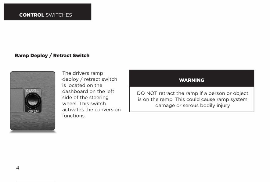
The drivers ramp deploy / retract switch is located on the dashboard on the left side of the steering wheel. This switch activates the conversion functions.
The back seat ramp deploy / retract switch is located on the C pillar behind the middle door near the foot of the rear seats. This switch activates the conversion functions.
Ramp Deploy / Retract Switch
4
DO NOT retract the ramp if a person or object is on the ramp. This could cause ramp system
damage or serous bodily injury
WARNING
OPERATION INSTRUCTIONS
5
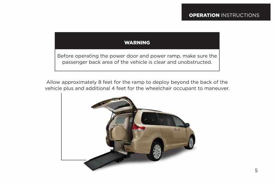
Before operating the power door and power ramp, make sure the passenger back area of the vehicle is clear and unobstructed.
WARNING
Allow approximately 8 feet for the ramp to deploy beyond the back of the vehicle plus and additional 4 feet for the wheelchair occupant to maneuver.

6
Instructions For Use:1. Place wheelchair in the vehicle facing forward and in a suitable position.
2. Preselect a position on the wheelchair to attach the hook and a position on the floor to attach the floor latch end of the strap
3. Release the buckle latch on the strap. With the buckle released, pull the webbing to create enough slack so that the restraint belt can be attached the floor and the wheelchair
4. Connect the floor latch to the pre-selected location on the floor track by pushing the fitting with even pressure into the track and slide the fitting in one direction until spring loaded latch drops into place. Pull on the strap to make sure it is secure
5. Find the handhold strap and pull to tighten the strap. Make sure there are no twists or knots in the strap
6. Lock buckle by pushing down until the buckle latch locks in place
7. Repeat the procedure for each of the four designated positions
SEATING SECUREMENT MANUAL OPERATION

SEATING SECUREMENT MANUAL OPERATION
7
Operate Door ManuallyWith the ramp in the fully stowed position, the back door may be opened or closed manually at any time. If automatic conversion ceases to operate you can manually deploy / retract the ramp.
1. Place the vehicle transmission in park
2. Open the rear door
3. Grasp the top edge of the ramp and pull the ramp out
4. As the ramp opens, gravity will force it to unfold until it reaches the ground

8
BENCH SECUREMENT
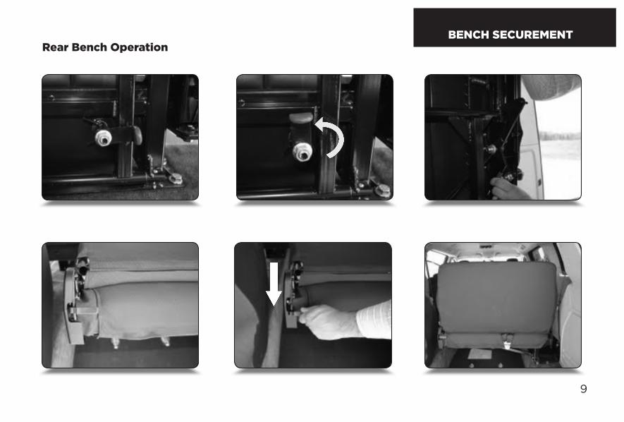
Rear Bench Operation
Note: This section only applies if your Kneelvan has beenequipped with a third-row two-passenger fold down bench.
Preparing the bench for use:
1: Release the Anti-Rattle lever located at bottom of the bench.
2: Release the Fold Down lever and carefully allow the bench to fold over until it locks into place.
3: Release the Back Rest lever and fold the back rest up until it locks into place. You may need to press down on the back rest to allow the Back Rest lever to release.
Rear Bench OperationBENCH SECUREMENT
9

10
TRANSFER SEAT OPERATION Operating your transfer seatNote: this section only applies if your Kneelvan has been
equipped with a driver-side or passenger-side Power Transfer Seat.
To use your Kneelvan’s Power transfer Seat:Make sure your chair or scooter is locked down and secured before attempting to transfer seats.
Ensure that the transfer seat has been slid completely forward using the OEM control (usually a bar or lever under the seat, or power controls) before operation.
Once you are properly seated, use the Swivel switch on your seat to turn yourself into the forward position. You may then use the Travel switch to begin sliding forward toward the front of the vehicle.
You may have to swivel the chair a little to avoid bringing the seat into contact with the door frame as you slide forward.
Warning: Contact between the chair and door panelcan cause damage to the panel or chair, or both!
Slide the seat completely into the forward position using the Travel switch to ensure that it is locked into place. You may then use the OEM controls to adjust the seat into a comfortable position.
Important: To provide the best level of safety, the power transfer seat must be completely in the forward position when the vehicle is in operation.
EZ LOCK OPERATION
11
www.ezlock.netWheelchair Docking Systems
TM
RELEASE DEACTIVATE
Wheelchair isLocked
READYWheelchair is NOTEngaged in Lock
STOPSystem Deactivated
DO NOT USE
WARNING
RELEASE
YELLOW LIGHTIndicates only partial docking pinengagement, The system usermust re-attempt entry.
GREEN LIGHTIndicates the docking pin on thewheelchair is fully engaged, andis ready for use.
RED LIGHTIndicates system has beendeactivated for occasionswhere the docking base isunoccupied.
DEACTIVATE SWITCHDeactivates the docking base alarmand release.ONLY to be used when the dockingbase is UNOCCUPIED.
RELEASE SWITCHUnlocks the docking base for 5seconds, allowing the systemuser to exit.
Guide to Docking System OperationFor the EZ Lock BL-6290 and BL-7317 Docking Bases
Thank you choosing the EZ Lock W heelchair Docking System ; Am erica’s #1 choice for quality and dependability. Before attem pting to use your EZ Lock W heelchair Docking System , be sure to fam iliarize yourself with the equipm ent and ensure that you thoroughlyunderstand the proper m ethod of docking system operation.
Docking System ControlsThe system control panel must be mounted in an area that is readily visible to the driver of the vehicle. The control panel provides a release switch as well as displaying the docking base system status through an array of colored lights and an audible alarm. The control panel also allows the system to be fully deactivated for occasions when the docking base is not being used. For passenger applications an additional release switch may be provided in an area closer to the docking station for the convenience of the passenger or attendant. FLASHING YELLOW AND RED LIGHTS COUPLED WITH A PULSING AUDIBLE ALARM INDICATE THE CONTROLS HAVE BECOME DETACHED FROM THE DOCKING BASE. DO NOT USE THE SYSTEM UNTIL THE PROBLEM CAN BE CORRECTED BY AN AUTHORIZED TECHNICIAN.
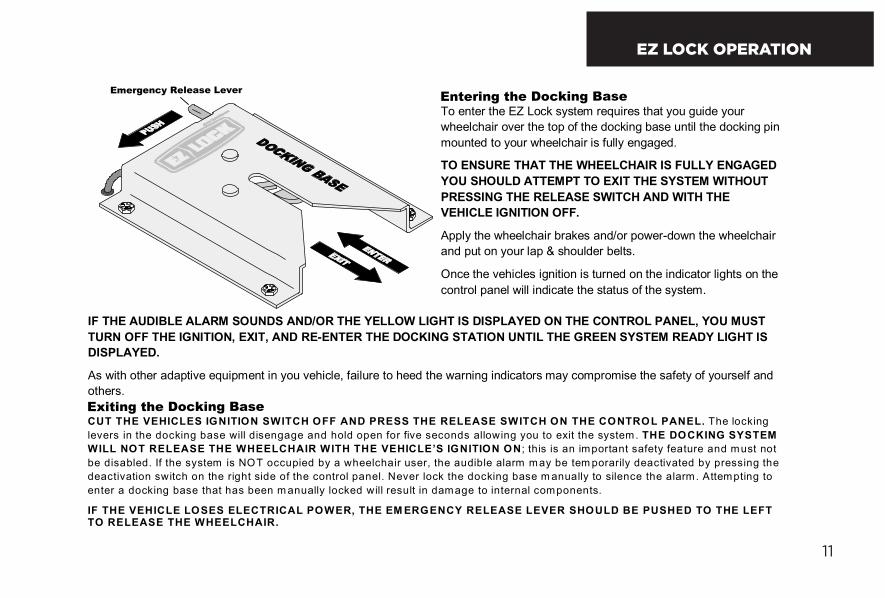
CUT THE VEHICLES IGNITION SWITCH OFF AND PRESS THE RELEASE SWITCH ON THE CONTROL PANEL. The locking levers in the docking base will disengage and hold open for five seconds allowing you to exit the system. THE DOCKING SYSTEM WILL NOT RELEASE THE WHEELCHAIR WITH THE VEHICLE’S IGNITION ON ; this is an important safety feature and must not be disabled. If the system is NOT occupied by a wheelchair user, the audible alarm may be tem porarily deactivated by pressing thedeactivation switch on the right side of the control panel. Never lock the docking base m anually to silence the alarm. Attempting to enter a docking base that has been m anually locked will result in damage to internal components.
IF THE VEHICLE LOSES ELECTRICAL POWER, THE EM ERGENCY RELEASE LEVER SHOULD BE PUSHED TO THE LEFT TO RELEASE THE WHEELCHAIR.
IF THE AUDIBLE ALARM SOUNDS AND/OR THE YELLOW LIGHT IS DISPLAYED ON THE CONTROL PANEL, YOU MUST TURN OFF THE IGNITION, EXIT, AND RE-ENTER THE DOCKING STATION UNTIL THE GREEN SYSTEM READY LIGHT IS DISPLAYED.
As with other adaptive equipment in you vehicle, failure to heed the warning indicators may compromise the safety of yourself and others.
Emergency Release LeverEntering the Docking BaseTo enter the EZ Lock system requires that you guide your wheelchair over the top of the docking base until the docking pin mounted to your wheelchair is fully engaged.
TO ENSURE THAT THE WHEELCHAIR IS FULLY ENGAGED YOU SHOULD ATTEMPT TO EXIT THE SYSTEM WITHOUT PRESSING THE RELEASE SWITCH AND WITH THE VEHICLE IGNITION OFF.
Apply the wheelchair brakes and/or power-down the wheelchair and put on your lap & shoulder belts.
Once the vehicles ignition is turned on the indicator lights on the control panel will indicate the status of the system.
COPYRIGHT © 2008 EZ Lock Inc.
Exiting the Docking Base

EZ LOCK OPERATION
12
www.ezlock.netWheelchair Docking Systems
TM
RELEASE DEACTIVATE
Wheelchair isLocked
READYWheelchair is NOTEngaged in Lock
STOPSystem Deactivated
DO NOT USE
WARNING
RELEASE
YELLOW LIGHTIndicates only partial docking pinengagement, The system usermust re-attempt entry.
GREEN LIGHTIndicates the docking pin on thewheelchair is fully engaged, andis ready for use.
RED LIGHTIndicates system has beendeactivated for occasionswhere the docking base isunoccupied.
DEACTIVATE SWITCHDeactivates the docking base alarmand release.ONLY to be used when the dockingbase is UNOCCUPIED.
RELEASE SWITCHUnlocks the docking base for 5seconds, allowing the systemuser to exit.
Guide to Docking System OperationFor the EZ Lock BL-6290 and BL-7317 Docking Bases
Thank you choosing the EZ Lock W heelchair Docking System ; Am erica’s #1 choice for quality and dependability. Before attem pting to use your EZ Lock W heelchair Docking System , be sure to fam iliarize yourself with the equipm ent and ensure that you thoroughlyunderstand the proper m ethod of docking system operation.
Docking System ControlsThe system control panel must be mounted in an area that is readily visible to the driver of the vehicle. The control panel provides a release switch as well as displaying the docking base system status through an array of colored lights and an audible alarm. The control panel also allows the system to be fully deactivated for occasions when the docking base is not being used. For passenger applications an additional release switch may be provided in an area closer to the docking station for the convenience of the passenger or attendant. FLASHING YELLOW AND RED LIGHTS COUPLED WITH A PULSING AUDIBLE ALARM INDICATE THE CONTROLS HAVE BECOME DETACHED FROM THE DOCKING BASE. DO NOT USE THE SYSTEM UNTIL THE PROBLEM CAN BE CORRECTED BY AN AUTHORIZED TECHNICIAN.
CUT THE VEHICLES IGNITION SWITCH OFF AND PRESS THE RELEASE SWITCH ON THE CONTROL PANEL. The locking levers in the docking base will disengage and hold open for five seconds allowing you to exit the system. THE DOCKING SYSTEM WILL NOT RELEASE THE WHEELCHAIR WITH THE VEHICLE’S IGNITION ON ; this is an important safety feature and must not be disabled. If the system is NOT occupied by a wheelchair user, the audible alarm may be tem porarily deactivated by pressing thedeactivation switch on the right side of the control panel. Never lock the docking base m anually to silence the alarm. Attempting to enter a docking base that has been m anually locked will result in damage to internal components.
IF THE VEHICLE LOSES ELECTRICAL POWER, THE EM ERGENCY RELEASE LEVER SHOULD BE PUSHED TO THE LEFT TO RELEASE THE WHEELCHAIR.
IF THE AUDIBLE ALARM SOUNDS AND/OR THE YELLOW LIGHT IS DISPLAYED ON THE CONTROL PANEL, YOU MUST TURN OFF THE IGNITION, EXIT, AND RE-ENTER THE DOCKING STATION UNTIL THE GREEN SYSTEM READY LIGHT IS DISPLAYED.
As with other adaptive equipment in you vehicle, failure to heed the warning indicators may compromise the safety of yourself and others.
Emergency Release LeverEntering the Docking BaseTo enter the EZ Lock system requires that you guide your wheelchair over the top of the docking base until the docking pin mounted to your wheelchair is fully engaged.
TO ENSURE THAT THE WHEELCHAIR IS FULLY ENGAGED YOU SHOULD ATTEMPT TO EXIT THE SYSTEM WITHOUT PRESSING THE RELEASE SWITCH AND WITH THE VEHICLE IGNITION OFF.
Apply the wheelchair brakes and/or power-down the wheelchair and put on your lap & shoulder belts.
Once the vehicles ignition is turned on the indicator lights on the control panel will indicate the status of the system.
COPYRIGHT © 2008 EZ Lock Inc.
Exiting the Docking Base
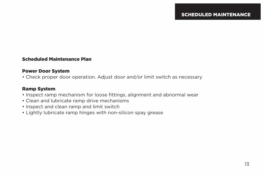
Scheduled Maintenance Plan
Power Door System• Check proper door operation. Adjust door and/or limit switch as necessary
Ramp System• Inspect ramp mechanism for loose fittings, alignment and abnormal wear• Clean and lubricate ramp drive mechanisms• Inspect and clean ramp and limit switch• Lightly lubricate ramp hinges with non-silicon spay grease
13
SCHEDULED MAINTENANCE
Record maintenance information in the table below
Date:
Description:
Date:
Description:
MAINTENANCE LOG
14
Date:
Description:
Date:
Description:
15
MAINTENANCE LOG

WARRANTY
16
FREEDOM MOTORS USA, INCORPORATED
CONVERSION COMPONENT LIMITED WARRANTY
Freedom Motors USA, Incorporated (“FMI”) provides a comprehensive Conversion Component Limited Warranty (“Warranty”). This Warranty is designed to work with any applicable Original Equipment Manufacturer (“OEM”) factory warranty.
WHAT IS COVERED?
This Warranty gives you specific legal rights. You may have other rights that vary from state to state. Under this Warranty, authorized FMI technicians or your personal technician, if approved by FMI, will, without charge, repair, replace or adjust all FMI conversion components (including all ramp parts, floor pan units, controls, systems and related accessories) (“conversion components”) on your vehicle that malfunction or fail from normal use during the applicable coverage period due to a manufacturing defect in FMI supplied materials or FMI workmanship. FMI may replace defective parts with new, remanufactured or used parts, at its discretion, so long as the replacement parts function properly with the conversion component.
While FMI’s defect experience is very low, this Warranty does not mean that each FMI conversion component is defect free. Defects may be unintentionally introduced into conversion components during the design and manufacturing processes and such defects could result in the need for repairs.
The remedy under this written Warranty, and any implied warranty, is limited to repair, replacement, or adjustment of defective conversion components. This exclusive remedy shall not be deemed to have failed its essential purpose so long as FMI is willing and able to repair, replace, or adjust defective conversion components in the prescribed manner. FMI’s liability, if any, shall in no event exceed the cost of correcting manufacturing defects as herein provided and upon expiration of this warranty, any such liability shall terminate.
Conditions that are not covered by this Warranty are described hereafter on pages 2 and 3. Nothing in this Warranty should be construed as requiring defective components to be replaced with parts of a different type or design than the original component, so long as the conversion components function properly with the replacement component. FMI, its technicians and your personal technicians approved by FMI, are entitled to a reasonable time and a reasonable number of attempts within which to diagnose and repair any defect covered by this Warranty.
THIS WARRANTY EXCLUDES CONSEQUENTIAL DAMAGES AND LIMITS THE DURATION OF ANY IMPLIED WARRANTIES TO THE DURATION OF THIS WARRANTY.

WARRANTY
17
WHAT ARE THE COVERAGE PERIODS?
- Newly manufactured and installed Kneelvan wheelchair van conversions and newly installed and manufactured Freedom Motors specialty conversions (i.e. Honda Element X-WAV conversions, Scion XS-Able conversions, etc.) are warranted for three (3) years or 36,000 miles, whichever occurs first;
- Wheelchair accessible commercial and handicap accessible taxi conversions are warranted for 12 months or 12,000 miles, whichever occurs first;
- Pre-owned Freedom Motors conversions sold by Freedom Motors are warranted for 12 months or 12,000 miles, whichever occurs first;
- Extended coverage periods may be available under the FMI Extended Warranty Plan as described on page 5.
WHEN DOES MY WARRANTY COVERAGE START?
Your coverage under the Warranty starts after completion of the conversion when you take delivery of your vehicle.
WHAT IS NOT COVERED?
Damage Caused By:
The Warranty does not cover damage caused by:-Accidents, collision or objects striking the vehicle (including driving through a car wash)-Theft, vandalism or riot-Fire or explosion-Using contaminated or improper fluids or lubricants-customer applied chemicals or accidental spills-Driving through water deep enough to cause water to be ingested into the conversion component controls-Misuse of the vehicle, such as driving over curbs, overloading, racing or using the vehicle as a permanent stationary power source
Damage Caused by Alteration or Modification:
The Warranty does not cover damage caused by:-Alterations or modifications to the conversion components-Tampering with the conversion components-Installation or use of a non-FMI approved part or component if it causes the FMI conversion components to fail
18
Damage Caused by Use and/or the Environment
The Warranty does not cover surface rust, deterioration and damage to paint, trim, upholstery, and other appearance items of the conversion components that result from use and/or exposure to the elements. You, as the owner, are responsible for these items. Some examples are:
-Dings and dents-Cuts, burns, punctures or tears-Road salt-Tree sap, bird and bee droppings-Windstorm, lightning or hail-Earthquake-Freezing, water or flood-Stone chips, scratches
Maintenance/Wear: The Warranty does not cover: (1) parts and labor needed to maintain the vehicle; and (2) the replacement of components due to normal wear and tear. You, as Owner, are responsible for these items.
LIMITATIONS AND DISCLAIMERS
The Warranty is subject to the following limitations and disclaimers:
The warranties expressed in this Warranty are the only express warranties applicable to conversion components. FMI does not assume or authorize anyone to assume for it any other obligation or liability in connection with its conversion components or the Warranty. No person, including FMI employees, may modify or waive any part of the Warranty.
FMI reserves the right to make changes in or additions to conversion components designed, manufactured or sold by it at any time and without incurring any obligation to make the same or similar changes or additions to conversion components previously designed, manufactured or sold by it.
FMI also reserves the right to provide post-warranty repairs, conduct recalls, or extend warranty coverage periods for certain conversion components, at the sole discretion of FMI. The fact that FMI has provided such measures to a particular conversion component group in no way obligates FMI to provide similar accommodations to other owners of similar conversion components.
As a condition of the Warranty, you are responsible for properly using, maintaining, and caring for your conversion components. FMI recommends that you maintain records and receipts of all maintenance records.
WARRANTY
WARRANTY
19
Fmi is not responsible for any time or income that you lose, any inconvenience you might be caused, the loss of your transportation or use of your vehicle, the cost of rental vehicles, fuel, telephone, travel, meals, or lodging, the loss of personal or commercial property, the loss of revenue, or for any other incidental or consequential damages you may have.
punitive, exemplary, or multiple damages may not be recovered unless applicable law prohibits their disclaimer.
you may not bring any warranty related claim as a class representative, private attorney general, a member of a class of claimants or in any other representative capacity.
fmi shall not be liable for any damages caused by delay in delivery or furnishing of any products and/or services.
you may have some implied warranties. For example, you may have an implied warranty of merchantability (that the conversion components are reasonably fit for the general purpose for which it was sold) or an implied warranty for fitness for a particular purpose (that the conversion components are suitable for a particular purpose), if a special purpose was specifically disclosed to fmi before your purchase and fmi told you the conversion component was would be suitable for that purpose.
these implied warranties are limited, to the extent allowed by law, to the time period covered by the written warranties, or to the applicable time period provided by state law, whichever period is shorter.
these implied warrranties, meaning the implied warrranty of merchantability and the implied warranty of fitness for a particular purpose, do not apply to your conversion components, and are specifically disclaimed, if you use your vehicle for business or commercial purposes or racing, even if the vehicle is equipped for racing.
The warranties contained herein and all questions regarding their enforceability and interpretation are governed by the law of the state in which the conversion components were sold to you. Some states do not allow FMI to limit how long an implied warranty lasts or to exclude or limit incidental or consequential damages so the limitation and exclusions discussed above may not apply to you.
HOW DO I GET WARRANTY SERVICE?FMI maintains an Open Source Service Plan. Our Open Source Service Plan provides a nationwide service network of authorized FMI technicians qualified to work on your conversion components. You can also use your own technician, subject to FMI’s pre-approval. To take advantage of our Open Source Service Plan, you need to follow these steps:
1.Call FMI’s 24-hour Service Hotline-Toll-Free at (800) 625-6335;
2.Tell us whether you want to use FMI’s Open Source Service Plan orprovide us with contact information for your personal technician
3.Describe the warranty claim or have your personal technician describe the warranty claim-failure to contact FMI prior to the commencement of warranty work will void the Warranty and you will have no Warranty coverage;
4.Receive approval in the form of a “work authorization with a work authorization number” from FMI that the claim is covered under the Warranty-you will not be eligible for reimbursement or payment of Warranty claims without a “work authorization number”.

Freedom Motors USA Inc. 740 Watkins Rd.
Battle Creek, MI 49015Phone 1.800.625.6335 Fax 269.660.5825

Freedom Motors USA Inc. 740 Watkins Rd.
Battle Creek, MI 49015Phone 1.800.625.6335 Fax 269.660.5825