this page intentionally left blank - gunnison management plan...7.3 selecting type of water quality...
TRANSCRIPT


THIS PAGE INTENTIONALLY LEFT BLANK

Table of Contents Chapter 1 General Provisions ........................................................................................................................................ 1
§1.0 Introduction ................................................................................................................................................. 1 §1.1 Authority ...................................................................................................................................................... 1 §1.2 Jurisdiction ................................................................................................................................................... 1 §1.3 Purpose ........................................................................................................................................................ 1 §1.4 Amendments ............................................................................................................................................... 2 §1.5 Enforcement Responsibility ......................................................................................................................... 2 §1.6 Review and Approval ................................................................................................................................... 2 §1.7 Interpretation .............................................................................................................................................. 2 §1.8 Relationship to other Standards .................................................................................................................. 3 §1.9 Waiver Requests .......................................................................................................................................... 3
Chapter 2 Guidelines, Policies and Minimum Standards ............................................................................................... 4 §2.0 Overall Criteria Goals ................................................................................................................................... 4 §2.1 Stormwater Management Guidelines ......................................................................................................... 4 §2.2 Planning and Implementation Considerations ............................................................................................ 5 §2.3 BMP Selection Guideline-Land Use Based ................................................................................................... 6 §2.4 Irrigation Ditch and Groundwater Policy ..................................................................................................... 9 §2.5 Minimum Standards Summary .................................................................................................................. 10
Chapter 3 Hydrology .................................................................................................................................................... 11 §3.0 Introduction ............................................................................................................................................... 11 §3.1 Design Rainfall – Intensity- Duration- Frequency (IDF) .............................................................................. 11 §3.2 Design Rainfall Distribution ....................................................................................................................... 13 §3.3 Snowmelt ................................................................................................................................................... 14 §3.4 Runoff ........................................................................................................................................................ 15 §3.5 Selection of Runoff Prediction Methods .................................................................................................... 17 §3.6 Rational Method ........................................................................................................................................ 17 §3.7 CUHP for Rainfall-Runoff Simulation ......................................................................................................... 23 §3.8 EPA SWMM for Rainfall-Snowmelt Runoff Simulation .............................................................................. 26 §3.9 Stormwater Quality ................................................................................................................................... 30 §3.10 References ................................................................................................................................................. 33
Chapter 4 Street Drainage ........................................................................................................................................... 35 §4.0 Purpose ...................................................................................................................................................... 35 §4.1 Design Storms ............................................................................................................................................ 35 §4.2 Street Classifications .................................................................................................................................. 35 §4.3 Construction Standards ............................................................................................................................. 35 §4.4 Design Considerations for Street Drainage ................................................................................................ 36 §4.5 Street-Side Swale (Bar Ditches) ................................................................................................................. 37 §4.6 Gutter Design ............................................................................................................................................. 38 §4.7 Inlet Functions ........................................................................................................................................... 40 §4.8 Culvert Construction Standards ................................................................................................................. 45 §4.9 Driveway Culvert Standards....................................................................................................................... 46 §4.10 Storm Sewers ............................................................................................................................................. 47 §4.11 References ................................................................................................................................................. 51
Chapter 5 Conduit Outlet Structures ........................................................................................................................... 53 §5.0 Introduction ............................................................................................................................................... 53 §5.1 General Layout Information ...................................................................................................................... 53 §5.2 Conduit Outlet Erosion Protection ............................................................................................................ 56 §5.3 Design Criteria for Culvert and Storm Sewer Outlet Erosion Protection ................................................... 57
Chapter 6 Detention .................................................................................................................................................... 58 §6.0 Overview .................................................................................................................................................... 58 §6.1 Types of Detention Basins ......................................................................................................................... 58 §6.2 Design Considerations ............................................................................................................................... 59

§6.3 Inlet and Outlet Works .............................................................................................................................. 60 §6.4 Design Procedure ....................................................................................................................................... 62 §6.5 Initial Design Detention Volumes .............................................................................................................. 63 §6.6 Preliminary Design ..................................................................................................................................... 72 §6.7 References ................................................................................................................................................. 73
Chapter 7 Stormwater Quality..................................................................................................................................... 74 §7.0 Introduction ............................................................................................................................................... 74 §7.1 Stormwater Quality Design Process .......................................................................................................... 74 §7.2 Sub-regional, Regional, and Onsite Approaches ........................................................................................ 75 §7.3 Selecting Type of Water Quality Capture Volume Facility ......................................................................... 75 §7.4 Exemptions from Post-Construction Best Management Practice Requirements ...................................... 75 §7.5 Design Criteria for Commonly Implemented Best Management Practices ............................................... 76 §7.6 Design Criteria for Other Best Management Practices .............................................................................. 81 §7.7 Source Control BMPs ................................................................................................................................. 88
Chapter 8 Drainage Report and Construction Drawing Submittal Requirements ..................................................... 107 §8.0 Introduction ............................................................................................................................................. 107 §8.1 Review Process ........................................................................................................................................ 107 §8.2 Summary Table of Required Certifications and City Action ..................................................................... 108 §8.3 Phase II Drainage Report and Plan........................................................................................................... 108 §8.4 Phase III Drainage Report and Plan.......................................................................................................... 114 §8.5 Special Drainage Reports ......................................................................................................................... 114 §8.6 Stormwater Facilities Maintenance Agreement ...................................................................................... 115 §8.7 Facilities Operation and Maintenance ..................................................................................................... 115 §8.8 Construction Drawings ............................................................................................................................ 115
Chapter 9 Construction Stormwater Management Best Management Practices ..................................................... 118 §9.0 Introduction ............................................................................................................................................. 118 §9.1 Fundamental Erosion and Sediment Control Principles .......................................................................... 119 §9.2 Colorado Construction Stormwater Discharge Permits ........................................................................... 120 §9.3 2009 Federal Effluent Limitation Guidelines ........................................................................................... 120 §9.4 Preparing and Implementing a Stormwater Management Plan (SWMP) ................................................ 121 §9.5 Inspections ............................................................................................................................................... 123 §9.6 Maintenance ............................................................................................................................................ 124 §9.7 Disposition of Temporary Measures ........................................................................................................ 124 §9.8 Construction BMPs .................................................................................................................................. 124 §9.9 BMP Selection and Planning .................................................................................................................... 127
Chapter 10 Facilities Operations and Maintenance .................................................................................................. 131 §10.0 Introduction ............................................................................................................................................. 131 §10.1 Preventive Measures to Reduce Maintenance Costs .............................................................................. 131 §10.2 Access and Easements ............................................................................................................................. 131 §10.3 Annual Inspection and Maintenance Report ........................................................................................... 131 §10.4 Features, Maintenance and Inspection of Stormwater Management Facilities...................................... 131
Appendices ................................................................................................................................................................ 137

Table of Figures Figure 1 Land Use and Future Development Patterns ................................................................................................... 7 Figure 2 BMP Decision Tree ........................................................................................................................................... 9 Figure 3 Rainfall IDF for Gunnison, CO ........................................................................................................................ 12 Figure 4 Soil Types ....................................................................................................................................................... 16 Figure 5 Runoff Coefficients for NRCS Hydrologic Soil Group A .................................................................................. 19 Figure 6 Runoff Coefficients for NRCS Hydrologic Soil Group B .................................................................................. 19 Figure 7 Runoff Coefficients for NRCS Hydrologic Soil Groups C and D ...................................................................... 20 Figure 8 Approximate Overland Flow Times for Small Lots ......................................................................................... 22 Figure 9 Illustration of Cascading Flow Layout ............................................................................................................ 25 Figure 10 Recommended Values for Design Variables Using Snowmelt Studies ........................................................ 27 Figure 11 Conveyance Facilities in Urban Area............................................................................................................ 29 Figure 12 Interception of Street Inlet .......................................................................................................................... 30 Figure 13 Effective Imperviousness of Tributary Area to BMP ................................................................................... 32 Figure 14 Imperviousness Adjustments for Level 1 and 2 MDCIA ............................................................................... 33 Figure 15 Cross Pan ..................................................................................................................................................... 37 Figure 16 Typical Swale Cross-Section ......................................................................................................................... 37 Figure 17 Catch-Type Curb and Gutter Unit ................................................................................................................ 39 Figure 18 Street and Gutter Cross-Section for a Local or Collector Street ................................................................. 39 Figure 19 Standard Curb Inlets .................................................................................................................................... 41 Figure 20 Example of Curb Opening Inlet in Sump ...................................................................................................... 44 Figure 21 Slotted Inlet ................................................................................................................................................. 44 Figure 22 Assumptions Regarding flow Interception by a Combination Inlet ............................................................. 45 Figure 23 Elliptical Sewer ............................................................................................................................................. 50 Figure 24 Box Sewer .................................................................................................................................................... 50 Figure 25 Conceptual Toe Wall Detail ......................................................................................................................... 54 Figure 26 Pipe Outfall Joint Restraint Requirements................................................................................................... 55 Figure 27 General Layout of a Detention Basin for Multiple Storm Events including WQCV ...................................... 60 Figure 28 Flow Chart for Detention Basin Design ........................................................................................................ 62 Figure 29 Detention Volume Example “Bow String” ................................................................................................... 64 Figure 30 Detention Volume by Hydrograph Method ................................................................................................. 65 Figure 31 Pre-shaping for a Triangular Basin ............................................................................................................... 66 Figure 32 Drop Box Outlet with Conduit to Release the 100-Year Flow ...................................................................... 67 Figure 33 Drop Box Outlet with Overtopping Spillway to Release 100-year Flow ...................................................... 68 Figure 34 Orifice Flow ................................................................................................................................................. 69 Figure 35 Sharp-Crested and Broad-Crested Weirs ..................................................................................................... 70 Figure 36 V-Notch and Trapezoidal Weir..................................................................................................................... 70 Figure 37 Outlet Culvert Hydraulics ............................................................................................................................. 71 Figure 38 Constructed Wetland Basin ......................................................................................................................... 83 Figure 39 Recommended Effective Percent Imperviousness for PPs .......................................................................... 87 Figure 40 Terms for Minimizing Directly Connected Impervious Area ........................................................................ 91 Figure 41 Concepts for Grass Swales ........................................................................................................................... 92 Figure 42 Concept for Concrete Edger ........................................................................................................................ 93 Figure 43 Concept for Outlet Structure with Parallel Wingwalls and Flush Bar Grating ............................................ 94 Figure 44 Concept for Outlet Structure with Flared Wingwalls and Handrail ............................................................ 95 Figure 45 Concept for Outlet Structure with Parallel Wingwalls and Flush Bar Grating ............................................ 96 Figure 46 Concept for Outlet Structure with Flared Wingwalls and Handrail ............................................................. 97 Figure 47 Concept for Integral Forebay at Pipe Outfall ............................................................................................... 98 Figure 48 Concept for Integral Forebay at End Section ............................................................................................... 99 Figure 49 Concept for Modified Extended Detention Basin for Small Sites .............................................................. 100 Figure 50 Concept for Modified Extended Detention Basin for Small Sites ............................................................. 101 Figure 51 Concept for Porous Landscape Detention in Parking Lot .......................................................................... 102 Figure 52 Concept for Porous Landscape Detention in Parking Lot ......................................................................... 103

Figure 53 Concepts for Inflows to Porous Landscape Detention in Parking Lot ........................................................ 104 Figure 54 Concepts for Porous Landscape Detention in Landscaping ....................................................................... 105 Figure 55 Concepts for Porous Landscape Detention Structures .............................................................................. 106 Figure 56 Components of Effective Stormwater Management at Construction Sites .............................................. 118 Figure 57 Erosion ....................................................................................................................................................... 119 Figure 58 Rilling ......................................................................................................................................................... 127 Table of Equations Equation 3-1 Rainfall Intensity Duration-Frequency (Inches/hr) ................................................................................. 12 Equation 3-2 Snowmelt Runoff Depth ......................................................................................................................... 15 Equation 3-3 Peak Flow ............................................................................................................................................... 17 Equation 3-4 Runoff Volume ....................................................................................................................................... 17 Equation 3-5 Rainfall Depth ......................................................................................................................................... 17 Equation 3-6 Overland Flow Time ............................................................................................................................... 20 Equation 3-7 Channel Flow Time ................................................................................................................................. 21 Equation 3-8 Time of Concentration ........................................................................................................................... 21 Equation 3-9 Regional Formula for Time of Concentration ......................................................................................... 21 Equation 3-10 Design Flow for Multiple Subareas ...................................................................................................... 22 Equation 3-11 Accumulated Travel Time through the Drainage Network .................................................................. 22 Equation 3-12 CUHP-1 ................................................................................................................................................. 24 Equation 3-13 Equation CUHP-2 .................................................................................................................................. 24 Equation 3-14 CUHP-3 ................................................................................................................................................. 25 Equation 3-15 CUHP-4 ................................................................................................................................................. 25 Equation 4-1 Capacity of a Swale ................................................................................................................................ 37 Equation 4-2 Capacity of a Swale ................................................................................................................................ 37 Equation 4-3 Capacity of a Swale ................................................................................................................................ 37 Equation 4-4 Capacity of a Swale ................................................................................................................................ 38 Equation 4-5 Capacity of a Swale ................................................................................................................................ 38 Equation 4-6 Open Channel Flow Theory for Gutter and Side Flows .......................................................................... 40 Equation 4-7 Flow Cross Sectional Area for Composite Street .................................................................................... 40 Equation 4-8 Effective Length of an on-grade inlet ..................................................................................................... 41 Equation 4-9 Effective Opening Area of an in-sump inlet ........................................................................................... 41 Equation 4-10 Design Flow on Street .......................................................................................................................... 42 Equation 4-11 Interception Percentage of the Side Flow ............................................................................................ 42 Equation 4-12 Total Interception Capacity .................................................................................................................. 42 Equation 4-13 Carry-Over flow for an On-Grade Grate Inlet ....................................................................................... 42 Equation 4-14 Weir-flow Capacity for an In-Sump Grate Inlet .................................................................................... 42 Equation 4-15 Weir Length around in-Sump Grate Inlet ............................................................................................. 42 Equation 4-16 Orifice-Flow Capacity for In-Sump Grate Inlet ..................................................................................... 43 Equation 4-17 Interception of Design Storm Runoff ................................................................................................... 43 Equation 4-18 Required Length for 100% Interception ............................................................................................... 43 Equation 4-19 Interception Capacity of an In-Sump curb-Opening Inlet .................................................................... 43 Equation 4-20 Modeling for In-Sump Curb-Opening Inlet ........................................................................................... 44 Equation 4-21 Storm Sewer Sizing ............................................................................................................................... 48 Equation 4-22 Accumulated Travel Time through Storm Sewer ................................................................................. 48 Equation 4-23 Inherent Time of Concentration .......................................................................................................... 49 Equation 4-24 Circular Sewer Hydraulics ..................................................................................................................... 49 Equation 4-25 Equivalent Diameter of Elliptical Sewer ............................................................................................... 50 Equation 4-26 Hydraulic Parameters in a Box Sewer .................................................................................................. 50 Equation 4-27 Sewer Energy and Hydraulic Grade Lines ............................................................................................. 50 Equation 6-1 Calculation of Inflow Volume ................................................................................................................. 63 Equation 6-2 Calculation of Outflow Volume .............................................................................................................. 63 Equation 6-3 Volume Difference (Storage) .................................................................................................................. 63

Equation 6-4 Outflow Rate for Detention Volume ...................................................................................................... 65 Equation 6-5 Detention Volume .................................................................................................................................. 65 Equation 6-6 Base Area of a Triangular Basin .............................................................................................................. 66 Equation 6-7 Top Cross Area of a Triangular Basin ...................................................................................................... 66 Equation 6-8 Volume of Triangular Basins................................................................................................................... 67 Equation 6-9 Orifice Flow ........................................................................................................................................... 68 Equation 6-10 Weir Flow ............................................................................................................................................ 69 Equation 6-11 Sharp and Broad-crested Weirs ........................................................................................................... 70 Equation 6-12 Stage-Flow for a V-Notch Weir ............................................................................................................ 70 Equation 6-13 Energy Balance in a Culvert .................................................................................................................. 71 Equation 6-14 Energy Balance for a Circular Pipe ....................................................................................................... 71 Equation 6-15 Energy Balance for a Non-Circular Pipe ............................................................................................... 71 Equation 6-16 Estimate of Tailwater Depth ............................................................................................................... 72 Equation 6-17 Loss Coefficients ................................................................................................................................... 72 Equation 6-18 Release Capacity of the Pipe ................................................................................................................ 72 Equation 9-1 Recommended Temporary Diversion Dike for Undisturbed Tributary Areas ...................................... 128 Equation 9-2 Recommended Temporary Diversion Dike for Disturbed Tributary Areas .......................................... 128 Equation 9-3 Recommended Temporary Diversion Dike for Paved Tributary Areas ................................................ 128 Equation 9-4 Revised Universal Soil Loss Equation (RUSLE) ...................................................................................... 129 Tables Table 1-1 Minor and Major Revisions ............................................................................................................................ 2 Table 2-1 Drainage Report Submittal Requirements ..................................................................................................... 6 Table 2-2 Development Types and Applicable Best Management Practices................................................................. 8 Table 3-1 Point Rainfall, Depth, Duration, Frequency in Gunnison, Colorado ........................................................... 12 Table 3-2 Rainfall Intensity Duration-Frequency in Gunnison, Colorado (Intensity in Inches/hr) ............................... 12 Table 3-3 Incremental Design Rainfall Distributions for Gunnison, Colorado ............................................................. 13 Table 3-4 Cumulative Design Rainfall Distributions for Gunnison, Colorado .............................................................. 14 Table 3-5 Infiltration Rates for Different Soil Groups (UDFCD, 2001) ......................................................................... 16 Table 3-6 Depression Losses for Various Land Uses (UDFCD, 2001) ........................................................................... 17 Table 3-7 Conveyance Coefficients for SCS Upland Method ....................................................................................... 21 Table 3-8 Monthly Evaporation Rates Inches/Month ................................................................................................. 27 Table 3-9 Flow Diversion of Street Inlet ...................................................................................................................... 30 Table 4-1 Minor and Major Street Systems Design Return Periods and Allowable spread ......................................... 36 Table 4-2 Clogging Factors for Inlet Design ................................................................................................................. 41 Table 4-3 Use of Trash/Safety Racks............................................................................................................................ 46 Table 5-1 Erosion Protection at Conduit Outlets ......................................................................................................... 56 Table 6-1 Detention Volume by Rational Volume Method ......................................................................................... 64 Table 6-2 Preliminary Storage Volume-Outflow Curve by Hydrograph Method ......................................................... 66 Table 6-3 Bend Loss Coefficients ................................................................................................................................. 72 Table 7-1 Grass Buffer and Swale Design Criteria ....................................................................................................... 76 Table 7-2 Wetland Pond Depth and Volume ............................................................................................................... 84 Table 7-3 Selection Matrix for Water Quality Capture Volume Facilities .................................................................... 90 Table 8-1 Drainage Report Submittal Requirements ................................................................................................. 107 Table 8-2 Summary of Required Certifications and City Action ................................................................................ 108 Table 9-1 Overview of Construction BMPs ................................................................................................................ 126 Table 10-1 Inspection and Maintenance Matrix for Specific Features of Stormwater Management Facilities ........ 134 Table 10-2 Summary of Routine Maintenance Activities for Stormwater Management Facilities ........................... 136

Did you intend to delete this table? I double checked and deleted those that no longer appear in the document. Acronyms As used in these Criteria, the following acronyms shall apply: ASCE American Society of Civil Engineers ASHC Allowable Street Hydraulic Capacity BMP Best Management Practice CDOT Colorado Department of Transportation CDPS Colorado Discharge Permit System CDPHE Colorado Department of Public Health and
Environment CLOMR Conditional Letter of Map Revision CMP Corrugated Metal Pipe CMPA Corrugated Metal Pipe Arch CRS Colorado Revised Statutes CUHP Colorado Urban Hydrograph Procedure CWB Constructed Wetland Basin DCIA Directly Connected Impervious Area EDB Extended Detention Basin EPA U.S. Environmental Protection Agency FAA Federal Aviation Administration FEMA Federal Emergency Management Agency FHWA Federal Highway Administration FIRM Flood Insurance Rate Map H:V Horizontal to Vertical Ratio of a Slope LID Low Impact Development LOMA Letter of Map Amendment LOMR Letter of Map Revision MDCIA Minimized Directly Connected Impervious
Area MUSLE Modified Universal Soil Loss Equation NOAA National Oceanic and Atmospheric
Administration NPDES National Pollutant Discharge Elimination
System NRCS Natural Resources Conservation Service ROW Right-of-Way RUSLE Revised Universal Soil Loss Equation SEO Colorado State Engineer’s Office SPCC Spill Prevention Control and
Countermeasure SWMM Stormwater Management Model SWMP Stormwater Management Plan UDFCD Urban Drainage and Flood Control District UDSWM Urban Drainage Stormwater Management
Model USDCM Urban Storm Drainage Criteria Manual WEF Water Environment Federation WQCV Water Quality Capture Volume

CHAPTER 1. GENERAL PROVISIONS
CITY OF GUNNISON STORMWATER MANAGEMENT MANUAL PAGE 1
Chapter 1 General Provisions §1.0 INTRODUCTION These criteria and design standards together with all future amendments shall be known as the City of Gunnison Stormwater Management Manual (Manual). This Manual is established as part of the City of Gunnison Construction Standards, by Resolution ## Series #### passed and adopted by the City Council. All development that is subject to the City of Gunnison Land Development Code, as amended (hereafter called the “LDC”) shall comply with the standards established by the Manual. All drainage reports and plans, drainage system analyses, and drainage system designs, that are submitted as a requirement of the LDC shall comply with the criteria presented in this Manual (herein after called the “Criteria”). §1.1 AUTHORITY It is the intention of the City Council in adopting this Manual to fully exercise all relevant powers conferred on it by the laws of the State of Colorado, including, but not limited to, the following: 1.1.1 Home Rule Municipality. All of the powers reserved to the City as a home rule municipality under Article XX of the Colorado Constitution.
1.1.2 State Enabling Legislation. All of the powers granted to the City by:
Title 29, Article 20, Colorado Revised Statutes (C.R.S.) provisions of the Local Government Land Use Control Enabling Act of 1974 (Title 29, Article 20, C.R.S.); Title 31, Article 12, C.R.S., provisions of the Colorado Municipal Annexation Act of 1965 (Title 31, Article 12 C.R.S.); Title 24, Articles 65, 67, and 68, C.R.S. provides for the review of areas and activities of state interest, authorize the Planned Development Overlay approach to land development and provide for the establishment of vested property rights; and Title 31, Article 23, C.R.S. enables municipalities to adopt zoning regulations and subdivision requirements.
1.1.3 All Other Powers Authorized. All other powers authorized by statute or by common law for the regulation of land uses, land development and subdivision, including, but not limited to, the power to abate nuisances. §1.2 JURISDICTION These Criteria shall apply to all land within the city limits. These Criteria shall apply to all systems and facilities constructed in or on City rights-of-way, easements dedicated for drainage across public or private property, easements for public use, and to all privately owned and maintained stormwater conveyance, detention, retention, or water quality facilities. §1.3 PURPOSE These Criteria are a compilation of policies and minimum technical criteria for the planning, analysis and design of storm drainage systems within the boundaries of the City of Gunnison. All subdivisions, re-subdivisions, planned unit development, and/or any other proposed land use or site development applications submitted for acceptance under the provisions of the LDC will provide adequate and appropriate storm drainage system planning, analysis, and design to ensure functional design, construction and maintenance.

CHAPTER 1. GENERAL PROVISIONS
PAGE 2 CITY OF GUNNISON STORMWATER MANAGEMENT MANUAL
§1.4 AMENDMENTS The policies and criteria may be amended as new technology is developed or if experience gained in the use of these Criteria indicates a need for revision. Minor amendments will require the approval of the Public Works Director. Major amendments will be subject to adoption by a resolution approved by the City Council. The Director of Public Works shall monitor the performance and effectiveness of these Criteria and will recommend amendments and revisions as needed.
TABLE 1-1 MINOR AND MAJOR REVISIONS MINOR MAJOR
Grammar Policy Changes Submittal Requirements Technical Criteria Changes Clarifications Major Construction Detail Revisions Construction Detail Revisions for clarification, minor modification
Any changes not listed herein
§1.5 ENFORCEMENT RESPONSIBILITY 1.5.1 The Public Works Director is hereby designated as the City Stormwater Policy Administrator and is authorized to act in the same capacity as the zoning administrator to enforce these Criteria. The Public Works Director shall follow the provisions of Section 13 (Enforcement) of the LDC. 1.5.2 The City Engineer shall review all drainage reports and plans, drainage system analyses, and drainage system designs, submitted as a requirement of the LDC, for compliance with these Criteria. The LDC is administered by the Director of Community Development or authorized representative. §1.6 REVIEW AND APPROVAL
1.6.1 The City shall review all drainage submittals for general compliance with these Criteria. Acceptance by the City does not relieve the owner, engineer, or designer from the responsibility of ensuring that the design, calculations, plans, specifications, construction, and record drawings are in compliance with these Criteria as stated in the owner’s and engineer’s certifications. 1.6.2 Submittals that impact FEMA designated floodplains shall be submitted to FEMA for review by the Community Development Director or the designated Floodplain Administrator. 1.6.3 The City may, at its discretion, refer submittals to other agencies that have an interest or responsibility for drainage and/or water quality issues. Other review agencies may include the Upper Gunnison Water Conservancy District; Gunnison County; Colorado Water Conservation Board; FEMA; U.S. Army Corps of Engineers; Colorado Geological Survey; or other relevant agencies. §1.7 INTERPRETATION The following shall govern in the interpretation and application of the provisions of these Criteria,:

CHAPTER 1. GENERAL PROVISIONS
CITY OF GUNNISON STORMWATER MANAGEMENT MANUAL PAGE 3
1.7.1 Criteria provisions shall be regarded as the minimum requirements for the protection of the public health, safety, comfort, morals, convenience, prosperity, and welfare of the residents of the City. These Criteria shall therefore be regarded as remedial and shall be liberally construed to further the underlying purposes. 1.7.2 Whenever a provision of these Criteria and any other provisions of the LDC or any provision in any law, ordinance, resolution, rule or regulation of any kind, contains any requirement(s) covering any of the same subject matter, the requirements that are more restrictive or impose higher standards shall govern. 1.7.3 These Criteria shall not abrogate or annul any easements, permits or approved drainage studies issued before the effective date of these Criteria, provided that the improvements have been constructed within the approval time period. Drainage studies, construction plans and permits which have expired approvals (i.e. improvements have not been constructed prior to the expiration of the approval date) shall be required to be resubmitted in accordance with the requirements of these Criteria. Drainage studies that have been approved through a previous land use process are not to be assumed as valid for a new land use submittal process. The Public Works Director shall have final authority to resolve any conflicting interpretations of these Criteria.
§1.8 RELATIONSHIP TO OTHER STANDARDS Storm drainage system planning, analysis, and design that require policies and technical criteria not specifically addressed in these Criteria shall follow the provisions of the Urban Drainage and Flood Control District’s (UDFCD) Urban Storm Drainage Criteria Manual, Volumes 1, 2, and 3, as amended (UDFCD Manual), which is incorporated in these Criteria by reference. If special districts impose more stringent criteria, this difference is not considered a conflict. If the State or Federal Government imposes stricter criteria, standards, or requirements, these may be incorporated into the City’s requirements after due process and public hearing(s), if needed, to modify the LDC and these Criteria. 1.8.1 At the time of the adoption of this manual the management and operation of the City’s stormwater facilities is not mandated to follow Phase II of the National Pollutant Discharge Elimination System (NPDES) Program Requirements of the Federal Clean Water Act, and regulations promulgated by the Colorado Department of Public Health and Environment – Water Quality Control Division in their Stormwater Phase II Program. However, in anticipation of future mandates, along with the City’s desire to promulgate sound development standards that protect, the basin’s water resources, the City will comply with Phase II NPDES requirements to the maximum extent practicable. 1.8.2 The City shall follow the “Reasonable Use Rule” to limit the rate and volume of flow from developing properties to the flow volume rates permitted by these Criteria. The basis for determining reasonable thresholds is based on historic undeveloped flow and volume rates determined for the site. 1.8.3 It is recognized that certain stormwater management facilities may impact water rights. The City shall preserve the integrity of water rights in the planning, design, and construction of stormwater drainage facilities. §1.9 WAIVER REQUESTS 1.9.1 Waiver from the provisions of these Criteria will be considered on a case-by-case basis. Requests for waiver from the standards or policies of these Criteria shall follow Waiver procedures established in Section 5 (Natural Resource Protection Standards) of the LDC.

CHAPTER 2. GUIDELINES, POLICIES AND MINIMUM STANDARDS
PAGE 4 CITY OF GUNNISON STORMWATER MANAGEMENT MANUAL
Chapter 2 Guidelines, Policies and Minimum Standards §2.0 OVERALL CRITERIA GOALS The overall goals of the criteria in the Manual include the following: 2.0.1 Provide full water quality treatment for up to the 80th percentile runoff event, corresponding to
between a 6-month and 1-year event. 2.0.2 For events larger than the 80th percentile event, BMPs designed in accordance with these criteria
will provide water quality treatment of the “first flush.”
2.0.3 Provide a high level of solids removal for typical suspended sediments found in urban runoff. §2.1 STORMWATER MANAGEMENT GUIDELINES The following guidelines are intended to provide direction in meeting the mandatory standards set forth in this manual and site development reviews required by Section 6 of the LDC. Following these guidelines will reduce the amount of stormwater runoff and pollutants that are generated; will provide for natural on-site control and treatment of runoff; and will optimize capital the investment of stormwater management facilities. These guidelines can be viewed as both water quantity and water quality management tools. 2.1.1 Drainage is a regional phenomenon that does not respect the boundaries between government jurisdictions, property boundaries, or adjacent land uses. 2.1.2 Stormwater management system planning and design for any site must be compatible with regional comprehensive plans, and should be coordinated with planning for land use, groundwater recharge, recreation, wildlife, wetland creation, protection of landmarks/amenities, open space, and transportation corridors. Urban stormwater management must consider and address the interrelated issues of erosion and sedimentation control, flood control, site grading, and regional water quality. 2.1.3 Design of the stormwater management system shall consider the features, capacity, and function of the existing drainage system. Good designs incorporate the effectiveness of the natural systems rather than negate, replace or ignore them. 2.1.4 Urbanization tends to increase downstream peak flows by increasing runoff volumes and the speed of runoff conveyance. Stormwater management systems shall be designed and detention storage shall be provided so as not to adversely impact downstream properties. 2.1.5 Every urban area has an initial (i.e., minor) and a major drainage system, whether or not they are actually planned and designed. The minor drainage system is designed to provide public convenience and to accommodate moderate, frequently occurring flows. The City requires that the minor drainage system be designed to convey runoff from the 5-year storm event. The major drainage system operates when the rate or volume of runoff exceeds the capacity of the minor system. The City requires that the major drainage system be designed to convey runoff from the 100-year storm event. Both systems must be planned and properly engineered. 2.1.6 Stormwater quality needs should be recognized early in the subdivision or development review process. Initial planning of a project provides opportunities to integrate stormwater quality facilities into a site can be fully realized.

CHAPTER 2. GUIDELINES, POLICIES AND MINIMUM STANDARDS
CITY OF GUNNISON STORMWATER MANAGEMENT MANUAL PAGE 5
2.1.7 New developments should reduce stormwater runoff rates and pollutant load to the maximum extent practicable. Efficient stormwater BMPs strive to reduce urban runoff volumes to more closely match natural conditions. Infiltration BMPs such as bioretention, sand filter detention and others promote greater volume reduction than extended detention basins, since runoff is reduced by infiltration. To the extent feasible, the imperviousness of the site should be minimized, the rate of runoff should be slowed by maximizing vegetative and porous land cover, and a series of best management practices must be provided for water quality enhancement and protection. 2.1.8 The stormwater management system is designed, beginning with the outlet or point of outflow from the project, giving full consideration to downstream effects and the effects of off-site flows entering the system. The design of the stormwater management system must account for runoff from upstream sites, assuming fully developed conditions, and must evaluate the downstream conveyance system to ensure that it has sufficient capacity to accept design discharges without adverse backwater or downstream impacts 2.1.9 The stormwater management system must receive regular maintenance to ensure long-term function and effectiveness. Facilities must be designed with ease of maintenance, long-term function, and accessibility as primary considerations. Clear assignment of maintenance responsibilities must be identified during the design review process. 2.1.10 Stormwater management improvements must be designed and constructed concurrently with development within a watershed. Development within a watershed creates an impact to the watershed that must be addressed through the design and construction of improvements. Development proposals must address these impacts and include the cost and implementation of stormwater management improvements within the Subdivision Improvements Agreement. 2.1.11 Regional or sub-regional Water Quality Capture Volume (WQCV) facilities must be designed and constructed at the time of subdivision to serve all parcels or lots within the subdivision boundary.
§2.2 PLANNING AND IMPLEMENTATION CONSIDERATIONS Technical criteria contained in this Manual focuses on sizing and design of stormwater systems and BMPs, but it is equally important to consider the general planning functions. Program planning considers the selection of BMPs based on project objectives and structural BMPs are considered along with other elements of the site planning process. The planning program function must consider implementation including proper design/construction of structural BMPs and long term maintenance needs. 2.2.1 General Site Design Considerations. While the design focuses on the functionality of the facilities within a stormwater system, it is important to create aesthetically pleasing facilities. Design must strive to preserve natural features and integrate facilities into the landscape plan. Illustrative site design should strive to integrate stormwater facilities, with site access, lot and building layout, site grading and landscaping. Early in the site design process a menu of appropriate structural BMPs, compatible with the related land use should be developed. Section 2.3 provides systematic guidance for identifying appropriate structural BMPs for the land uses found in the City. In general, the initial sizing of detention basin area is about 12 percent of the total impervious area, and should be shallow and provide for vegetative growth. The area may be reduced in conjunction with the development of the engineered design. The use of public rights-of-way may be necessary in very constrained sites, but the City will only consider such options on a site-by-site basis and under a License Agreement approved by the City Council; maintenance responsibilities will not be accepted by the City.

CHAPTER 2. GUIDELINES, POLICIES AND MINIMUM STANDARDS
PAGE 6 CITY OF GUNNISON STORMWATER MANAGEMENT MANUAL
The City encourages design that conveys surface runoff through structural BMPs rather than pipes. If surface flow can be conveyed through grass swales or strips of porous media, additional water quality benefits are realized and water quality capture volumes are reduced. If buried pipe conveyance is needed, landscaped inlets are preferred over curb inlets to increase infiltration potential. Design approaches should be tailored to specific pollutant concerns. §2.3 BMP SELECTION GUIDELINE-LAND USE BASED 2.3.1 Land Use and Stormwater Management Strategies. Developed areas within the historic core of the City will continue to be served by the existing stormwater system. The existing stormwater system is a series of buried gravity-pipe utilities with outfalls located within the east-central portion of the Airport, at Mergleman Pond and in the Gunnison River near the Sunspot Subdivision. [Talk to Terry about a basin map.] Specific stormwater strategies should focus on opportunities associated with infill and redevelopment, and reducing water volume and improving the function of the existing outfall structures of the existing system. Stormwater management within the Gunnison Rising Annexation will follow the stormwater master plan developed for the annexation site. Defining strategies for stormwater management is subject to where future development will occur and the existing/future land use patterns found within the municipal boundary. Future development will consist of infill, primarily within the West Gunnison neighborhood planning area and the VanTuyl Village subdivision, and the phased expansion of the Gunnison Rising Annexation (City of Gunnison Master Plan, 2007). A mosaic pattern of land uses, derived by historic development and the annexation of Gunnison Rising, are found within the City boundary. Six general land use categories have been identified for the purpose of defining different conceptual strategies for stormwater quality treatment. Additionally, the street system must be considered as an overlay element of the land use pattern. These land use categories are generally based on dimensional building standards and impervious coverage for specific zoning districts in the City (Table 2-1). The land use patterns and future development areas are depicted on Figure 1.
TABLE 2-1 DRAINAGE REPORT SUBMITTAL REQUIREMENTS
LAND USE TYPE ZONING CATEGORY Urban Intensive – high percent of impervious surface Central Business District
Industrial District – excluding Airport High Density Multiple Family
Commercial Highway Corridor Commercial District Low and Medium Density Residential R-1, R-2, RMU, B-1 Institution/Campus WSC, Commercial and Residential Districts Parks and Open Space VanTuyl Ranch, limited airport property Airport “Airside” facilities Industrial Streets - Are an overlay associated with all use categories

CHAPTER 2. GUIDELINES, POLICIES AND MINIMUM STANDARDS
CITY OF GUNNISON STORMWATER MANAGEMENT MANUAL PAGE 7
FIGURE 1 LAND USE AND FUTURE DEVELOPMENT PATTERNS
The relationship between various land uses and determining appropriate structural BMPs to fulfill stormwater quality treatment involves a systematic assessment of runoff off reduction, determining treatment volume (Water Quality Control Volume – WQCV), considering flood detention needs and considering implementation details. The design may include a mixture of approaches from different development types to best meet the needs of a particular project. Table 2-2 provides a menu of potentially applicable BMPs for the defined land use categories. 2.3.2 Scale Considerations. On-site BMPs typically provide treatment for an area that is on the order of 1 acre-or less. They are typically constructed as the development is built and they are privately owned and maintained. Sub-regional BMPs treat runoff from a neighborhood or small watershed area (multiple properties), typically ranging from more than 1 acre to approximately 90 acres. There is often an economy of scale for sub-regional facilities because the footprint required to provide an overall storage volume is generally less if a single facility is used as opposed to multiple smaller facilities with multiple embankments and appurtenances. Areas larger than five acres (typical of a sub-regional BMP) commonly use extended dry detention basins and constructed wetland basins, managed by a district. The city may accept the dedication of large facilities, but only if a dedicate revenue source for operation and maintenance is established.

CHAPTER 2. GUIDELINES, POLICIES AND MINIMUM STANDARDS
PAGE 8 CITY OF GUNNISON STORMWATER MANAGEMENT MANUAL
TABLE 2-2 DEVELOPMENT TYPES AND APPLICABLE BEST MANAGEMENT PRACTICES
DEVELOPMENT TYPE/BMPS
RUNOFF REDUCTION/CONVEYANCE BMPS STORAGE VOLUME BMPS SUB-SURFACE BMPS
MDCIA Vegetated Swales
Grass Buffers
Pervious Pavement
Constructed Wetland Channel
Grass Swale Sed.
Bioretention Pervious Pavement Detention
Extended Detention
Basin (EDB)
Sand Filter EDB
Constructed Wetlands
Basin
Sed./ Filtration
Vaults
Dry Wells
Urban Intensive + ! ! + X ! ! + X ! X ! ! X ! + , X
Low to Medium Density Residential + + + + X , + + X + X + + X , ! , X
Commercial Highway Corridor
+ , , + X ! , + X + X + + X ! + , X
Airport Airside Facilities + + + + , + + + , , + ! !
Institutional Campus + + + + X , + + X + X + + X + ! ! X
Streets + + X ! , + X ! X ! + X ! + , X
Parks, Natural Areas and Open Space + + + + X + + + X + X + , X + ! ! X
On-Site (OS), Sub-Regional (SR), or Regional (R)
OS OS OS OS SR, R OS OS OS SR, R OS, SR SR, R OS OS
+ = Highly Applicable , = Somewhat Applicable ! = Not Recommended X = Sand Not for use in Sanded Areas—some of these BMPs may be applicable if adequate pretreatment is provided MDICA = Minimize Directly Connected Impervious Area

CHAPTER 2. GUIDELINES, POLICIES AND MINIMUM STANDARDS
CITY OF GUNNISON STORMWATER MANAGEMENT MANUAL PAGE 9
Regional BMPs are large-scale facilities that treat runoff from areas typically greater than 90 acres. Regional BMPs offer an economy of scale in terms of size requirements and costs; however, since the capital costs for regional facilities are typically large, funding of facilities to keep pace with development can be difficult. When on-site and sub-regional facilities are not feasible, regional facilities may be necessary. Regional facilities are usually publicly owned and maintained. 2.3.3 Best Management Practices Selection. In addition to land use and development type, other factors are important for selecting the appropriate BMP for a site. These factors include soil type and permeability, size of tributary area, depth to groundwater and bedrock, pretreatment provided, and others. Figure 2 provides a decision tree that can be used to determine appropriate BMP for a site in conjunction with the development type guidance from Sections 2.3.1 through 2.3.2.
FIGURE 2 BMP DECISION TREE
§2.4 IRRIGATION DITCH AND GROUNDWATER POLICY 2.4.1 Irrigation Ditches. Stormwater runoff must be directed to historic and natural drainageways and avoid discharging into irrigation ditches to the maximum extent feasible, except as required by water rights. Development should provide the appropriate structure to separate stormwater runoff from ditch flows. If development proposes to increase flow rates, volumes, change points of discharge into irrigation ditches, the written consent from the ditch owner/operator must be submitted with the development application. The discharge of runoff into the irrigation ditch should be approved only if such discharge is consistent with an adopted master drainage plan or when storm events exceed the design capacity of on-site BMPs.

CHAPTER 2. GUIDELINES, POLICIES AND MINIMUM STANDARDS
PAGE 10 CITY OF GUNNISON STORMWATER MANAGEMENT MANUAL
2.4.2 Groundwater Investigations. Groundwater can affect the function of stormwater management facilities and other infrastructure. It is the engineer’s responsibility to quantify potential impacts and to develop designs which mitigate any potential impacts. The City requires developers to provide an appropriate analysis and discussion of potential groundwater impacts within their development and identify potential solutions to address the impacts. §2.5 MINIMUM STANDARDS SUMMARY 2.5.1 Site Design. Site designs will preserve the natural drainage and treatment systems, reduce the generation of additional stormwater runoff and pollutants, and increase infiltration of stormwater into the ground, rather than into hard infrastructure, to the fullest extent practicable. 2.5.2 Design. Historic discharge rates must be maintained by all stormwater drainage designs. 2.5.3 Water Quality Capture Volume (WQCV). New development and redevelopment shall treat a volume of water equal to the 80th percentile runoff event for their site. This volume has been sized to remove 90 percent of particles greater than 60 microns in size by releasing the WQCV over a 12-hour period. The WQCV is determined based on the site’s impervious area and can be reduced as impervious area is reduced. Guidelines for calculating the WQCV, reducing the WQCV, and designing structural controls capable of treating the WQCV are detailed in §3.9.1. 2.5.4 Detention. New development and redevelopment, not served by the city’s existing stormwater facilities, shall detain for the minor and major storm event up to the point that the stormwater system downstream can accommodate. In most cases, a site will be controlling the post-development peak discharge rate to the predevelopment rate for the 10- and 100-year event. Guidelines for calculating required detention and designing detention facilities are detailed in §2.5.5. 2.5.5 Stormwater System. The downstream system from each site must be able to safely pass flows from the 5- or 10-year and 100-year event. A downstream hydrologic analysis must be performed to determine if there are any additional impacts in terms of peak flow increase or downstream flooding while meeting minimum standards 2.5.1 and 2.5.3. This analysis must be performed at the discharge points of the site and, at a minimum, at the next two downstream structures. 2.5.6 Floodplains. Development and redevelopment is restricted in both FEMA-floodplains and other tributary streams as determined by the City floodplain administrator. Developments near streams may be required to generate floodplain data for their site and meet the requirements detailed in Chapter 3 . 2.5.7 Grading. Grading and drainage designs must be considered early in the design process as they can have a significant impact on the design of the site. Conceptual plans are required to show investigation and plans for all of the above standards.
CHAPTER 3. HYDROLOGY
CITY OF GUNNISON STORMWATER MANAGEMENT MANUAL PAGE 11
Chapter 3 Hydrology §3.0 INTRODUCTION This chapter summarizes methodology for determining rainfall and runoff information for the design of stormwater management facilities in the City. The methodology is based on the procedures presented in the UDFCD Manual in the Rainfall and Runoff Sections. The design procedures outlined in the UDFCD Manual, supplemented by the information provided in this section, apply to all projects in the City.
3.0.1 Stormwater Quality Considerations. The increase in runoff from development is especially pronounced when drainage systems are designed to quickly and “efficiently” convey paved area and roof runoff directly into inlets and storm sewers, discharging eventually into drainageways that are typically designed to convey flows at maximum acceptable velocities. Whether for one site or for a whole watershed, this increase in runoff and acceleration of flood peaks is reflected accurately by the hydrologic methods discussed herein. With proper planning, the increased runoff volumes, rates, and pollutant loads can be managed and controlled in ways that mimic natural hydrology, reducing the impacts to the watershed. Stormwater management policies of the City of Gunnison strongly encourage methods to reduce runoff and increase infiltration to attenuate peak flood discharges and improve stormwater quality.
§3.1 DESIGN RAINFALL – INTENSITY- DURATION- FREQUENCY (IDF) Many drainage facilities are designed for watersheds smaller than 100 acres with a time to peak discharge of less than 30 minutes. This requires the use of rainfall patterns that are shorter than two-hour duration in the facilities design. Rainfall frequency (2-, 5-, 10-, 20-, 50- and 100-year) events are plotted on distribution cures derived for Gunnison based on the one hour precipitation depth. However, only the 5-, 10- and 100-year storms are needed for drainage design at this time. Rainfall data used in the City of Gunnison is based on the National Oceanic and Atmospheric Administration Precipitation-Frequency Atlas of the Western United States, Volume III-Colorado (NOAA Atlas), published in 1973. Precipitation depth maps shown in the NOAA Atlas were used to determine representative 1hour and 6 hour point rainfall values for the City. The methodology used to generate the rainfall data for a project will depend on the size of the drainage basin being studied. The Rational Method for determining runoff from relatively small basins may be used for drainage basins with an aggregate area less than 90 acres. The Rational Method uses rainfall data in the form of intensity, duration, and frequency curves discussed this chapter.
3.1.1 Rainfall Depth-Duration-Frequency-Intensity. The rainfall intensity-duration-frequency (IDF) curve is a statistical formula describing the relationship among the local rainfall characteristics and return periods. The IDF curve is used in the Rational Method for peak runoff predications of basins smaller than 90 acres. The IDF curve for the City of Gunnison can be derived according to the location (N1060 55' 36" Latitude W380 32' 39" longitude) and elevation (7,700 feet). IDF data for events less than one hour are established using ratio data found in Short Duration Rainfall Relations of the Western United States (Arkell R.E., F. Richards, 1986, AMS Conference on Climate and Water Management).

CHAPTER 3. HYDROLOGY
PAGE 12 CITY OF GUNNISON STORMWATER MANAGEMENT MANUAL
TABLE 3-1 POINT RAINFALL, DEPTH, DURATION, FREQUENCY IN GUNNISON, COLORADO 5-min 10-min 15-min 30-min 1-hr 2-hr 3-hr 6-hr 24-hr 2-yr 0.13 0.20 0.26 0.36 0.45 0.54 0.59 0.70 1.00 5-yr 0.20 0.31 0.39 0.54 0.68 0.79 0.86 1.00 1.40 10-yr 0.25 0.38 0.48 0.67 0.85 0.97 1.05 1.20 1.60 25-yr 0.32 0.50 0.63 0.87 1.10 1.20 1.27 1.40 2.00 50-yr 0.40 0.62 0.79 1.09 1.38 1.46 1.51 1.60 2.20 100-yr 0.48 0.76 0.94 1.22 1.51 1.61 1.69 1.80 2.40 TABLE 3-2 RAINFALL INTENSITY DURATION-FREQUENCY IN GUNNISON, COLORADO (INTENSITY IN INCHES/HR)
5-min 10-min 15-min 30-min 1-hr 2-hr 3-hr 6-hr 24-hr 2-yr 1.57 1.22 1.03 0.71 0.45 0.27 0.20 0.12 0.04 5-yr 2.37 1.84 1.55 1.07 0.68 0.39 0.29 0.17 0.06 10-yr 2.96 2.30 1.94 1.34 0.85 0.48 0.35 0.20 0.07 25-yr 3.38 2.97 2.51 1.74 1.10 0.60 0.42 0.23 0.08 50-yr 4.80 3.73 3.15 2.18 1.38 0.73 0.50 0.27 0.09 100-yr 5.80 4.53 3.74 2.45 1.51 0.80 0.56 0.30 0.10 The following equation can be used to determine intensities not shown in the IDF table or curve. The equation is used with the Rational Method by setting Td equal to the time of concentration of the watershed.
EQUATION 3-1 RAINFALL INTENSITY DURATION-FREQUENCY (INCHES/HR)
𝐼 = 29𝑃1
(10 + 𝑇𝑑)0.789
Where I = rainfall intensity (inch/hr), P1 = 1hour rainfall depth (inches), and Td = duration or time of concentration (minutes)
FIGURE 3 RAINFALL IDF FOR GUNNISON, CO
0.00
1.00
2.00
3.00
4.00
5.00
6.00
7.00
5 10 15 20 25 30 35 40 45 50 55 60
Inten
sity (
inche
s/hr)
Duration in Minutes
IDF Rainfall for Gunnison, Colorado
2-yr 5-yr 10-yr 25-yr 50-yr 100-yr

CHAPTER 3. HYDROLOGY
CITY OF GUNNISON STORMWATER MANAGEMENT MANUAL PAGE 13
§3.2 DESIGN RAINFALL DISTRIBUTION A temporal distribution must be assigned to a precipitation event for calculation of runoff for larger drainage areas (≥ 90 acres) or for sizing of facilities, such as a detention pond, where a hydrograph must be analyzed. Characteristics of a temporal distribution include duration and distribution (depth at a certain time) of rainfall. Very intense rainfall patterns resulting from convective storms or frontal stimulated convective storms typically drive flooding in small urban catchments like Gunnison. These types of storms have their most intense periods over duration of one or two hours or less, and they produce brief periods of high rainfall intensities. Summer storms in Gunnison are usually intense rainstorms with their greatest intensities in the first hour of the storm event. Depth ratios (or percentages) are input parameters of the Colorado Urban Hydrograph Procedure (CUHP) models. From this manual, another step was taken to derive distribution depths (these can also be input for the CUHP models) for the one-hour event in Gunnison. Table 3-3 shows the incremental depths and Table 3-4 shows the cumulative depths.
Time Minutes
TABLE 3-3 INCREMENTAL DESIGN RAINFALL DISTRIBUTIONS FOR GUNNISON, COLORADO
2-Year (in)
5-Year (in)
10-Year (in)
25-Year (in)
50-Year (in)
100-Year (in)
5 0.26 0.39 0.49 0.41 0.52 0.48 10 0.81 1.13 1.42 1.73 2.17 2.27 15 2.15 3.37 3.97 3.14 3.93 4.31 20 4.76 6.87 8.42 5.81 7.29 7.98 25 8.22 12.43 15.53 12.06 15.13 15.45 30 4.98 6.98 8.06 21.73 27.26 30.58 35 2.38 3.31 4.00 11.08 13.90 17.71 40 1.99 2.64 3.23 7.77 9.75 10.66 45 1.24 2.25 2.98 5.07 6.36 8.62 50 1.29 2.34 2.6 5.26 6.59 7.21 55 1.33 2.01 2.68 3.47 4.36 5.96 60 1.35 2.04 2.72 3.52 4.42 6.04 65 1.41 2.13 2.83 6.37 4.60 6.29 70 0.96 2.17 2.90 2.81 3.53 3.22 75 0.98 1.85 2.96 2.87 3.61 3.29 80 1.00 1.66 2.36 2.20 2.76 2.01 85 1.02 1.69 1.83 2.24 2.81 2.05 90 1.03 1.72 1.86 1.77 2.22 2.08 95 1.05 1.75 1.89 1.80 2.26 2.12
100 1.07 1.21 1.91 1.82 2.29 2.15 105 1.08 1.23 1.94 1.85 2.32 2.18 110 1.09 1.24 1.96 1.87 2.35 2.20 115 0.55 1.26 1.78 1.90 2.38 2.23 120 0.54 0.00 1.26 1.68 2.04 1.93

CHAPTER 3. HYDROLOGY
PAGE 14 CITY OF GUNNISON STORMWATER MANAGEMENT MANUAL
§3.3 SNOWMELT The average snowfall in the Gunnison area is about 50 inches. Snowmelt and refreezing can lead to many drainage problems in the spring. An evaluation of snowmelt events can be helpful in selection of alternatives for snow management, determining snow storage, and for determining capacities of stormwater quality controls. However snowmelt evaluations are not necessary at this time for development design in Gunnison. 3.3.1 Snow Compaction and Snow-to-Water Ratios. Snow deposit settles under its own weight until its density is approximately 30 percent water. Increases in density above this initial compression occur primarily by melting and refreezing. A snow removal study for Berthoud Pass over US Highway 40 reported the compact ratio for piled snow is 43 percent (GUO 1999). Under different compact conditions 10 inches of fresh snow can contains between 0.11 to 4.0 inches of water, depending on crystal structure, wind speed, temperatures and other factors. The City sets the snow to water ratio at 11 inches of fresh snow equivalent to one inch of water.
Time Minutes
TABLE 3-4 CUMULATIVE DESIGN RAINFALL DISTRIBUTIONS FOR GUNNISON, COLORADO
2-Year (in)
5-Year (in)
10-Year (in)
25-Year (in)
50-Year (in)
100-Year (in)
5 0.26 0.39 0.49 0.41 0.52 0.48 10 1.07 1.53 1.91 2.15 2.69 2.75 15 3.23 4.90 5.88 5.28 6.63 7.05 20 7.98 11.77 14.30 11.09 13.92 15.03 25 16.20 24.20 29.84 23.16 29.05 30.49 30 21.18 31.18 37.89 44.88 56.30 61.06 35 23.56 34.49 41.89 55.96 70.20 78.81 40 25.55 37.13 45.11 63.73 79.95 89.47 45 26.79 39.39 48.09 68.79 86.30 98.09 50 28.08 41.73 50.69 74.05 92.90 105.31 55 29.41 43.74 53.37 77.52 97.26 111.27 60 30.76 45.78 56.09 81.04 101.67 117.31 65 32.17 47.90 58.93 84.71 106.27 123.60 70 33.13 50.08 61.83 87.52 109.80 126.82 75 34.11 51.93 64.79 90.40 113.41 130.11 80 35.11 53.59 67.15 92.60 116.17 132.12 85 36.13 55.28 68.97 94.84 118.98 134.17 90 37.16 57.00 70.83 96.61 121.20 136.25 95 38.21 58.75 72.72 98.40 123.45 138.37
100 39.28 59.96 74.63 100.23 125.74 140.51 105 40.36 61.18 76.57 102.08 128.06 142.69 110 41.45 62.42 78.53 103.95 130.41 144.89 115 42.01 63.68 80.31 105.85 132.79 147.13 120 42.55 63.68 81.57 107.53 134.83 149.06

CHAPTER 3. HYDROLOGY
CITY OF GUNNISON STORMWATER MANAGEMENT MANUAL PAGE 15
3.3.2 Snowmelt Runoff Depth. It is assumed that daily snowmelt is proportional to the difference between the representative daily temperature and a base temperature (Viessman et. al. 1997).
EQUATION 3-2 SNOWMELT RUNOFF DEPTH
Ps = Ks (Tm -32) Where Ps = snowmelt depth (inches of water) Ks= degree-day snowmelt coefficient (inch/day-0F) = 0.011 inch/day-°F Tm = maximum daily temperature (0F)
§3.4 RUNOFF 3.4.1 Overview. Pervious surface areas allow water to infiltrate into the ground. Impervious surface areas produce direct runoff as soon as it rains. The percent of impervious areas is the most sensitive parameter to the runoff generation. Estimates of runoff flow rates and volumes for selected levels of protection provide the basis for the design of drainage facilities in relation to flood discharges and water quality in a drainage system. The following discussion provides criteria for the design peaks, and volumes and methods to calculate urban runoff generated in the City of Gunnison. Methods describe herein include: • The Rational Method applicable to watersheds less than 90 acres; • The Colorado Urban Hydrograph Procedure (CUHP) developed for larger watersheds; and • The EPA Storm Water Management Model (SWMM) Version 5, applicable to snowmelt runoff
predictions or urban watersheds with on-site low impact development treatments. 3.4.2 Hydrologic Loss – Soil Infiltration Loss. Soil type is the most important factor in determining the infiltration rate. The Natural Resources Conservation Service (NRCS) has classified soils into four hydrologic types; the hydrologic soils found in the city are depicted in Figure 4. Engineering Soil Groups: Type A Soil – Soils having high infiltration rates such as sand and gravel Type B Soil – Soils having moderate infiltration rates such as loamy soils Type C Soil – Soils having moderate to low infiltration such as clay soils Type D Soil – Soils having low to very low infiltration

CHAPTER 3. HYDROLOGY
PAGE 16 CITY OF GUNNISON STORMWATER MANAGEMENT MANUAL
Infiltration rates are described by a decay function with a high rate at the beginning of the event when the soil is dry and a low rate when the soil substrate becomes saturated. Table 3-5 is recommended for design infiltration rates for use in CUHP and SWMM modeling, but is not needed in the Rational Method. When the watershed has several different types of soils, the representative infiltration rate may be determined as an area weighted value.
TABLE 3-5 INFILTRATION RATES FOR DIFFERENT SOIL GROUPS (UDFCD, 2001) Soil Type
Initial Rate Inch/hr
Final Rate Inch/hr
Decay Coefficient 1/sec for CUHP
Decay Coefficient 1/hr for SWMM
A 5.0 1.0 0.0007 2.52 B 4.5 0.6 0.0018 6.48 C 3.0 0.5 0.0018 6.48 D 3.0 0.5 0.0018 6.48
3.4.3 Hydrologic Loss – Depression Loss. Depression loss is expressed as the lump sum of the entrapped water volume in inches per watershed. Table 3-6 is a summary of the recommended depression capacity for use in CUHP/SWMM modeling. Depression losses are not needed for the Rational Method.
FIGURE 4 SOIL TYPES

CHAPTER 3. HYDROLOGY
CITY OF GUNNISON STORMWATER MANAGEMENT MANUAL PAGE 17
§3.5 SELECTION OF RUNOFF PREDICTION METHODS Determination of flows at a design point requires a representative topographic map of the tributary watershed and defined boundaries of all relevant drainage basins. Basins to be defined include all basins tributary to the area of study and sub-basins in the study area. Field checks and possibly field surveys must be completed before initiating preliminary drainage planning. Flow diversions and irrigation ditches must also be investigated because they can transfer stormwater across the watershed boundaries. The second step is to select the runoff prediction method, which depends on design needs and watershed size. The Rational Method may be used for determining peak flow from water shed areas less than 90 acres. The Rational Method is sufficient for culvert sizing to pass the design peak flow from a watershed less than 90 acres. In larger watersheds (≥90 acres) the rainfall–runoff process is more complicated because hydrologic losses vary more and the simplified Rational Method is not appropriate. Large watershed hydrographs can be computed using the CUHP or SWMM. SWMM can also be used to determine snowmelt runoff hydrographs. CUHP is required for detention basin design because the procedure involves hydrograph routing. SWMM can be used to study the alternatives for snow removal and redistribution along the streets in the developed urban area of the City. §3.6 RATIONAL METHOD The Rational Method is a simplified hydrologic method developed for peak flow prediction in small watersheds (< 90 acres). It is applicable to street inlet sizing, sewer drain design, and single lot developments in the City of Gunnison. The Rational Method states (Kuiching, 1889):
EQUATION 3-3 PEAK FLOW
Peak Flow = Qp = CIA
EQUATION 3-4 RUNOFF VOLUME
Runoff Volume = Vr = 𝐶12
P A
EQUATION 3-5 RAINFALL DEPTH
Rainfall Depth = P = 𝑇𝑑60
I in which,
Qp = peak flow (peak runoff) in cubic feet per second (cfs),
TABLE 3-6 DEPRESSION LOSSES FOR VARIOUS LAND USES (UDFCD, 2001) LAND COVER RANGE
INCHES DESIGN VOLUME
INCHES Large Paved Area 0.05 – 0.15 0.10 Flat Roofs 0.10 – 0.30 0.10 Sloped Roofs 0.05 -0.10 0.05 Lawn Grass 0.20 – 0.50 0.03 Wooded Area 0.20 – 0.60 0.40 Open Fields 0.20 – 0.60 0.40 Sandy Area 0.02 Loams 0.15 Clay 0.10

CHAPTER 3. HYDROLOGY
PAGE 18 CITY OF GUNNISON STORMWATER MANAGEMENT MANUAL
I = rainfall intensity in inch/hour, A = drainage area in acres, C = runoff coefficient, Vr = runoff volume in acre-feet, P = rainfall depth in inches, and Td = rainfall duration (or time of concentration Tc) in minutes.
The flow (Qp) must be calculated at each design point, starting at the upstream end of the watershed and proceeding downstream. Each watershed must be analyzed for the minor and major storm events. In most cases the minor event is the 10 year storm and the major event is the 100 year storm. As indicated, the basic input parameters for the Rational Method include watershed area, runoff coefficient, and design rainfall intensity. The rainfall intensity-duration-frequency (IDF) formula is applied to determine rainfall intensity (I). The rainfall IDF formula for the City of Gunnison can be found in §3.1 above. The general procedure for Rational Method calculations for a single basin is described with section citations related to the particular procedure element. 1. Delineate the basin boundary. Measure its area (acres). See Section 3.6.1. 2. Identify the soil types(s) See Figure 4 Soil Types 3. Determine Runoff Coefficient, C. See Section 3.6.2. 4. Define the flow path from the upper-most portion of the basin to the design point. This flow path
must be divided into reaches of similar flow type (e.g. overland flow, shallow swale flow, gutter flow, etc.). The length and slope of each reach must be measured.
5. Determine the time of concentration TC for the catchment. See Section 3.6.3. 6. Find the rainfall intensity, I, for the design storm using the calculated TC and the rainfall intensity-
duration-frequency curve. See §3.1. 7. Calculate the peak flow rate from the watershed. See Equation 3-3. 3.6.1 Watershed Area. The watershed drainage boundary lines are determined by grading and slopes, the location of downspouts and inlets, paved and unpaved areas, site grading and many other features. 3.6.2 Runoff Coefficients and Percent Impervious for Land Uses. The runoff coefficient, C, is derived to represent the ratio of runoff to rainfall volumes during the event. The determination of runoff coefficient mainly depends on the soil type, watershed imperviousness and storm event frequency. Gravel parking areas, storage areas, and access drives as proposed on site improvements plan should be analyzed as impervious surface. The runoff coefficient is a function of the hydrologic soil group within the basin and the imperviousness of the basin. Use the tables from the Urban Storm Drainage Criteria Manual 1 (UDFCD), which follow, to determine the runoff coefficient for the appropriate storm event.

CHAPTER 3. HYDROLOGY
CITY OF GUNNISON STORMWATER MANAGEMENT MANUAL PAGE 19
FIGURE 6 RUNOFF COEFFICIENTS FOR NRCS HYDROLOGIC SOIL GROUP B
FIGURE 5 RUNOFF COEFFICIENTS FOR NRCS HYDROLOGIC SOIL GROUP A

CHAPTER 3. HYDROLOGY
PAGE 20 CITY OF GUNNISON STORMWATER MANAGEMENT MANUAL
FIGURE 7 RUNOFF COEFFICIENTS FOR NRCS HYDROLOGIC SOIL GROUPS C AND D
3.6.3 Time of Concentration. The design rainfall duration used in the Rational Method equals the runoff flow time required through the longest waterway (starting at the most hydraulically distant point) within the watershed. A waterway can be divided into reaches: the overland flow reach, and any number of channel flow reaches. The time of concentration of the watershed is the cumulative flow times through the reaches.
A. Overland Flow Time. The water velocity of overland flow is a function of watershed slope and waterway roughness. There are many empirical formulas developed for estimating the overland flow time. The following formula is recommended for the calculation of overland flow time in an urban setting (McCuen et al 1984):
EQUATION 3-6 OVERLAND FLOW TIME
𝑇𝑜 =0.395(1.10 − C5)�Lo
So 0.33
in which,
To = overland flow time in minutes, Lo = overland flow length in feet, So = overland slope in ft/ft, and C5 = 5-year runoff coefficient.
The maximum length for overland flow is up to 300 feet in a developed area and 500 feet in a rural area. Development is symbolized by street curbs, gutters and inlets. Under a rural condition, stormwater flows through natural depressions, turf strips and grass swales that significantly slow down the flow.

CHAPTER 3. HYDROLOGY
CITY OF GUNNISON STORMWATER MANAGEMENT MANUAL PAGE 21
B. Channel Flow Time. Channel flow time (or concentrated flow time) is the travel time of water in swales, gutters, channels, or the storm sewer. Channel flow time should be calculated separately for each reach that demonstrates different hydraulic properties such as slopes or material lining. The Soil Conservation Service (SCS) upland method was developed to estimate the flow time through shallow swale flows.
EQUATION 3-7 CHANNEL FLOW TIME
𝑇𝑓 =
𝐿𝑓60𝑉𝑓
where 𝑉𝑓 =𝐾�𝑆𝑓 or 𝑇𝑓 =
𝐿𝑓
60∗𝐾�𝑆𝑓
in which, Tf = flow time in minutes, Lf = flow length in feet, Vf = flow velocity in feet/second, Sf = reach slope in ft/ft, and K = conveyance coefficient as described in Table 3-7 (Guo 2006).
TABLE 3-7 CONVEYANCE COEFFICIENTS FOR SCS UPLAND METHOD LININGS FOR CONVEYANCE CONVEYANCE COEFFICIENT
Meadow (rough bushes) 2.5 Tillage (crop fields, mountain vegetation) 4.5 Lawn (turf strip, gravel pavement) 7.0 Bare soils (unlined ditches) 10.0 Grass Lined Swale (grass ditches) 15.0 Paved Water Way (street gutters) 20.0
C. Time of Concentration. The computed time of concentration, Tc, is the sum of the overland and channel flow times.
EQUATION 3-8 TIME OF CONCENTRATION
Tc = To + Tf
The computed time of concentration is sensitive to the overland flow length. To be conservative, the time of concentration to be used in design in the City of Gunnison is set to be the smaller between the computed and regional times of concentration. The regional formula for time of concentration is (UDFCD 2008, CCHCDDM 1999):
EQUATION 3-9 REGIONAL FORMULA FOR TIME OF CONCENTRATION
𝑇𝑅 = 10 + 𝐿180
in which TR = regional time of concentration in minutes, and L = total waterway length in feet.
In no case should a Tc be less than 5 minutes in the City of Gunnison. If the computed or regional time of concentration calculations indicate a lesser time, use 5 minutes instead. Figure 8 is the plot to estimate the overland flow time using Equation 3-8 with C5=0.88 for paved flow path. (Did you mean to delete this sentence? If so, do we need Figure 8?)

CHAPTER 3. HYDROLOGY
PAGE 22 CITY OF GUNNISON STORMWATER MANAGEMENT MANUAL
3.6.4 Design Flow for Multiple Sub-Areas. Hydrologic homogeneity is one of the basic assumptions for small watershed hydrology. If the land uses or soil types in a watershed vary from one area to another, then it is necessary to divide the watershed into sub-areas. Each sub-area should have its own outlet that is termed “node” or “design point.” All nodes shall then be connected together by swales, street gutters, sewers, or roadside ditches that are often referred to as “link.” A node-link schematic represents the flow connectivity through the watershed. The flow process through multiple subareas starts from the most upstream subarea to accumulate the flow time through the drainage network. At the n-th node on the waterway, the accumulated contributing area is:
EQUATION 3-10 DESIGN FLOW FOR MULTIPLE SUBAREAS
(𝐴𝑒)𝑛 = 𝐶𝑛 𝐴𝑛 + ∑ 𝐶𝑖𝑖=𝑛−1𝑖=1 𝐴𝑖
The accumulated travel time through the drainage network is:
EQUATION 3-11 ACCUMULATED TRAVEL TIME THROUGH THE DRAINAGE NETWORK
(𝑇𝑐)𝑛 = (𝑇𝑐)𝑛−1 + 𝐿𝑛60𝑉𝑛
in which,
Ae = effective contributing area in acres, Tc = accumulated time of concentration in minutes through the waterway system, L = waterway length in feet, V = flow velocity in feet/sec, i = i-th node upstream of the design point, and n = n-th node at the design point.
FIGURE 8 APPROXIMATE OVERLAND FLOW TIMES FOR SMALL LOTS
CHAPTER 3. HYDROLOGY
CITY OF GUNNISON STORMWATER MANAGEMENT MANUAL PAGE 23
When several links come to a node, the design rainfall duration or time of concentration at the node is the longest flow time among all incoming links. Knowing the contributing area and flow time, the peak discharge can be predicted by the Rational Method.
3.6.5 Excel-based Computer Model – RATIONAL. RATIONAL is an excel-based computer model RATIONAL is featured with the capabilities of computing the average runoff coefficient using the area-weighted method, time of concentration for multiple reaches, design rainfall intensity and peak flow using the Rational Method (Guo, Urbonas, MacKenzie, and Lloyd 2007). §3.7 CUHP FOR RAINFALL-RUNOFF SIMULATION Background. The Colorado Urban Hydrograph Procedure (CUHP) is a synthetic unit hydrograph method that was developed and calibrated by the rainfall-runoff data collected from the Denver and Boulder metropolitan areas in Colorado. CUHP2005 is an excel-based computer program that provides numerical automation using CUHP to generate hydrographs at design points. These computed hydrographs can be saved into a text file that can be imported into EPA SWMM Version 5 (SWMM5) for channel and reservoir routing. Both CUHP2005 and SWMM5 computer models have been widely accepted and applied to stormwater simulation studies in the State of Colorado. These models are free and can be downloaded at the web addresses below (you had deleted the web addresses). Because both of these models are well documented with complete user manuals, this chapter will only focus on model inputs for applications in the City of Gunnison rather than the equations and numerical methods used in the models. http://www.udfcd.org/downloads/down_software.html http://www.epa.gov/ednnrmrl/models/swmm/index.html 3.7.1 CUHP Input Parameters. CUHP is an empirical procedure to predict runoff hydrographs using the synthetic unit hydrograph method (Snyder 1938, Sherman 1932). A CUHP2005 computer model is composed of rainfall data, sub-area hydrologic parameters, and options for various printout format, and user-defined practices. Details are discussed as follows:
A. Design Rainfall. CUHP requires the input of a design rainfall distribution expressed as incremental rainfall depths in inches with a pre-selected time interval such as 1, 5, 10, or 15 minutes. All the 2-hr design rainfall curves discussed in Chapter 3 can be generated by CUHP2005 using the one-hour rainfall depth. The user has the option to enter an observed rainfall distribution with duration up to 6 hours or 72 time steps with a time interval of 5 minutes. The rainfall duration for the unit hydrograph should be 5 minutes for most urban areas. However, such duration may be increased to 10 or 15 minutes for larger watersheds or decreased to one minute for smaller watersheds.
B. Watershed Input Parameters. CUHP can accept infinite watersheds in one computer run. A
large watershed is divided into smaller watersheds between 100 to 150 acres in size. As a rule of thumb, the watershed length to width ratio shall not exceed 4:1. The following input data must be entered for each watershed:
Horton’s Infiltration Rates (see Table 3-5) Pervious and Impervious Depression in inches (Table 3-6) Watershed Area (square miles) – the tributary area is used to generate runoff hydrograph.

CHAPTER 3. HYDROLOGY
PAGE 24 CITY OF GUNNISON STORMWATER MANAGEMENT MANUAL
Length of Waterway (miles) – the length of the waterway should be the longest flow path from the most upstream boundary to the outlet point. It shall be measured by following the waterway meandering pattern. Length to Centroid (miles) – the centroid of a watershed is the geometric center that can be measured based on the area’s shape and size. Projecting the area-centroid laterally onto the waterway locates the waterway centroid. From the waterway centroid to the outlet gives the length to centroid. Percent Impervious (%) – the portion of the watershed’s surface area that is impervious or paved. Percent impervious is expressed as a percent value between zero and 100. Waterway slope in ft/ft – waterway slope is an important and sensitive factor when calculating the time parameters used in CUHP. A waterway shall be divided into several reaches, according to the uniformity of the invert slope that is calculated as:
EQUATION 3-12 CUHP-1
𝑆𝑖 = 𝐻𝑖𝐿𝑖
In which Si = slope for i-th reach, Hi = vertical drop in elevation, and Li = length of reach. Equation CUHP-1 shall be applied to all reaches in order to produce the length-weighted slope as:
EQUATION 3-13 EQUATION CUHP-2
𝑆𝑜 = �1𝐿
∑ (𝐿𝑖 𝑆𝑖0.24𝑖=𝑛𝑖=1 )�
4.17
In which So = waterway representative slope in ft/ft, and L = total length of waterway. Equation CUHP-2 is operated with topographic maps that do not reveal the drops and lining roughness through the waterway. When the measured slope is steeper than 4%, it is subject to a correction. For instance, 5.7% shall be entered into CUHP for the measured slope of 8%.
C. User Option to Reshape Unit Graph. The program, CUHP2005, computes the time to peak
coefficient, Ct, and peak parameter, Cp, according to the watershed area and imperviousness percentage. However, the user has an option of overriding the computed values for these parameters. The shape of the unit hydrograph also relies on proportioning the widths at 50% and 75% of the unit hydrograph peak. The proportioning is based on 0.35 of the time-width at 50% of peak being ahead of the time to peak and 0.45 of the time-width at 75% of peak being ahead of the time to peak. If the user has derived unit hydrographs from other sources, CUHP allows the user to reshape the unit hydrograph according to the user-defined time-widths.
D. User Option to Define Cascading Flows for Low Impact Layout. The CUHP2005 computer
model recognizes the effects of cascading flows in which the unconnected impervious areas drains onto porous area for additional infiltration effects. With the concept of cascading flow, a typical urban watershed may have four separate surface runoff components as:
• Impervious area directly connected to the drainage system (DCIA) • Impervious area that drains onto or across pervious surfaces (UIA)

CHAPTER 3. HYDROLOGY
CITY OF GUNNISON STORMWATER MANAGEMENT MANUAL PAGE 25
• The pervious area receiving runoff from impervious portions (RPA) • The separate pervious area (SPA) not receiving runoff from impervious surfaces
Two design variables are defined as:
EQUATION 3-14 CUHP-3
𝐷 = 𝐷𝐶𝐼𝐴𝐼𝐴
EQUATION 3-15 CUHP-4
𝑹 = 𝑹𝑷𝑨𝑷𝑨
IA = total impervious area, DCIA = directly (hydraulically) connected impervious area, D = fraction of the total impervious area directly connected to the drainage system, RPA = receiving pervious area, PA = total pervious area, R = fraction of pervious area receiving disconnected impervious runoff, SPA = separate pervious area, and UIA = unconnected impervious area.
FIGURE 9 ILLUSTRATION OF CASCADING FLOW LAYOUT
The following watershed parameters are also optional inputs and are available to the user to account for the effects of directly connected/disconnected impervious areas: • DCIA (Directly Connected Impervious Area) is the input variable that specifies the on-site
drainage pattern. Option 1 represents the Standard Management Practice (SMP) in which the impervious and pervious areas are independently, separately drained onto the street. Option 2 represents the Best Management Practice (BMP) in which the impervious area drains onto porous area before the street.
• D is the variable to define the fraction of the total impervious area directly connected to the drainage system. It ranges from 0.01 to 1.0.
• R is the variable to define the fraction of total pervious area receiving runoff from the disconnected impervious areas. It ranges from 0.01 to 1.0.
Although CUHP provides the default values for R and D used in SMP and BMP, the user has the option of replacing the default with the user-defined values.

CHAPTER 3. HYDROLOGY
PAGE 26 CITY OF GUNNISON STORMWATER MANAGEMENT MANUAL
E. File Management. CUHP2005 provides three options to structure the printout in a spreadsheet
format, including summary for watersheds, unit hydrographs, and storm hydrographs respectively. CUHP2005 is a hydrograph generator that does not have any hydrologic routing capability. The user has options to save all the predicted hydrographs in a text file and then transfer this file into the EPA SWMM5 computer model as an input file for various hydrologic routing features. Details can be found in the CUHP2005 user manual.
§3.8 EPA SWMM FOR RAINFALL-SNOWMELT RUNOFF SIMULATION 3.8.1 Background. The current edition of EPA Stormwater Management Model 5 (SWMM5) provides an integrated environment for editing study area input data; running hydrologic, hydraulic and water quality simulations; and viewing the results in a variety of formats (Rossman 2005). SWMM5 is a dynamic rainfall-runoff simulation model used for single event or long-term simulation of rainfall and snowmelt runoff for both quality and quantity studies. The runoff component of SWMM5 operates on a watershed area that receives precipitation and generates runoff and pollutant loads. The routing portion of SWMM5 transports this runoff through a system of pipes, channels, storage/treatment devices, pumps, and regulators. SWMM5 tracks the quantity and quality of runoff generated within each watershed, and the flow rate, flow depth, and quality of water in each pipe and channel during a simulation period comprised of multiple time steps. 3.8.2 SWMM Input Parameters. A SWMM5 computer model consists of four basic components: (1) Time Variables, (2) Climatology Parameters, (3) Watershed Parameter, and (4) Network for Hydrologic Routing. SWMM accepts interface files to transfer pre-processed rainfall or runoff data sets into a SWMM computer model to speed up simulations. The option of Rainfall Interface File is used to load a long term rainfall or snowfall record into the SWMM computer model for simulation studies. It is important to understand that a CUHP/SWMM in-tandem model does not need Climatology and Watershed Parameters in the SWMM model because the pre-processed CUHP hydrographs can be directly transferred into the SWMM model for Hydrologic Routing. Details of interface files (Option of Inflow) can be found in the SWMM User Manual (Rossman, 2005).
A. Time Variable. SWMM follows the clock time to conduct rainfall and runoff analyses. The user must specify the beginning and the end of the storm event and the time steps used for computation and reporting. B. Climatology (not needed if CUHP is used). Rain Gage is the object for the user to define the design rainfall distribution that can be expressed in incremental volume or intensity for each time step. Air Temperature is used when simulating snowfall and snowmelt processes during runoff calculations. Temperature data are not required for rainfall and runoff simulations. Evaporation can occur to standing water on watershed surfaces, for subsurface water in groundwater aquifers, and for water held in storage units such as detention basins. Evaporation rates can be prescribed as a single constant value, a set of monthly average values as shown in Table 3-8, or a user-defined time series of daily values.

CHAPTER 3. HYDROLOGY
CITY OF GUNNISON STORMWATER MANAGEMENT MANUAL PAGE 27
Wind Speed is an optimal climatic variable that is only used for snowmelt calculations. SWMM can use either a set of monthly average wind speeds or wind speed data contained in the same climate file used for daily minimum/maximum temperatures. Snowmelt Parameters are climatic variables that apply across the entire study area when simulating snowfall and snowmelt. They include: (a) the air temperature, such as 32F°, at which precipitation falls as snow (b) heat exchange properties of the snow such as Antecedent Temperature Index (ATI) and negative melt ratio, and (c) surface study area elevation, latitude, and longitude correction. Figure 10 is the summary of the recommended values for snowmelt studies for the Gunnison area.
FIGURE 10 RECOMMENDED VALUES FOR DESIGN VARIABLES USING SNOWMELT STUDIES
Areal Depletion refers to the tendency of accumulated snow to melt non-uniformly over the surface of a watershed. As the melting process proceeds, the area covered by snow gets reduced. This behavior is described by an Aerial Depletion Curve that plots the fraction of total area that remains snow covered against the ratio of the actual snow depth to the depth at which there is 100% snow cover. Snow Pack Parameters characterize the buildup, removal, and melting of snow over three types of storage areas within a watershed, including (a) the plowable snow pack area as a user-defined fraction
TABLE 3-8 MONTHLY EVAPORATION RATES INCHES/MONTH BLUE MESA RESERVOIR
Jan1 Feb1 Mar1 Apr May Jun July Aug Sep Oct Nov Dec1 0.00 0.00 0.00 0.2.88 4.08 5.64 6.48 6.60 6.36 5.64 4.92 0.00
1Ice Cover so values are set to zero

CHAPTER 3. HYDROLOGY
PAGE 28 CITY OF GUNNISON STORMWATER MANAGEMENT MANUAL
of the total impervious area, (b) the impervious snow pack area covers the remaining impervious area of a watershed, and (c) the pervious snow pack area encompasses the entire pervious area of a watershed.
C. Watershed Input Parameters (not needed if CUHP is used). Based on the land uses and types of soils, a watershed is divided into smaller subareas for stormwater analyses. Among these subareas, the hydrographs are routed and combined along the drainage network. The following input data must be entered for each subarea. Subarea (in acres) is the tributary area used to generate runoff hydrograph and pollutant loadings. Width of Subarea (in feet) is referred to the collector channel across the Kinematic Wave (KW) plane. As a rule of thumb, the width of the KW plane is approximated to be twice the length of the waterway (Guo and Urbonas 2009). Subarea Slope (in percent) represents the average slope on the KW plane. The transverse slope of the watershed is a good approximation (Guo 1998). Percent Impervious represents the imperviousness percentage of the subarea between 0 and 100. Manning’s N’s for pervious and impervious surfaces are used to calculate flood wave movement. Overland flow is a two-dimensional sheet flow that is significantly affected by the surface resistance. As recommended, the value of 0.25 is used for pervious surface, and 0.025 is for impervious surface. Pervious and Impervious Depression in inches (See Table 3-6). Percent of Zero-Imperv is the variable that represents the percent of impervious area with no depression storage such as roof area in a subarea. A value of 25% is recommended. Subarea Routing represents the arrangement of cascading flows on the KW plane. IMPERV means the upper porous area draining onto the lower impervious area. PERV is the option to drain the upper impervious area onto the lower porous area and OUTLET implies that the pervious and impervious areas are separately drained or no cascading flow at all. Percent Routed is the variable that quantifies the percent of the upper area draining onto the lower area when cascading inlet option is selected. Soil Loss Parameters are user-defined infiltrating rates used in Horton’s formula (see Table 3-7). Downstream Junction Node is the object to represent the location where the hydrograph generated from a subarea is placed. Between two junction nodes is a channel or a pond. A node (similar to a manhole) is described by it invert elevation and the maximum and initial water depths if the node is surcharged in case of flooding, the user can specify the ponded area in square feet atop the junction.
3.8.3 Drainage Network for Hydrologic Routing. Hydrologic routing schemes are numerical methods to transport hydrographs through a channel or a reservoir by solving the equation of continuity. A kinematic wave (KW) routing method ignores the backwater effect while a Dynamic Wave (DW) routing method takes into consideration the flow acceleration and the storage effects under the backwater profiles. In comparison, DW calculations are sensitive to the time increment. The rule of thumb is to select a short time step such as 1 to 60 seconds for DW calculations and 300 seconds or longer for KW

CHAPTER 3. HYDROLOGY
CITY OF GUNNISON STORMWATER MANAGEMENT MANUAL PAGE 29
calculations. To be conservative, the KW model is recommended for stormwater planning studies while the DW model can be accepted for on-site stormwater designs and detailed studies. Hydrologic routing schemes in SWMM5 are classified into conveyance routing, flow diversion, and detention basin routing.
A. Conveyance Flow Routing for Channels and Pipes. Urban area flows are collected and conveyed by streets, sewers, roadside ditches, and channels. As illustrated in Figure 11, these conveyance facilities are modeled as: Case 1: Street and Sewer Section representing a street with an underground sewer Case 2: Culvert and Overtopping Flow representing a crossing culvert underneath a roadway Case 3: Street and Roadside Ditch representing a street with a swale ditch Case 4: Overbank Channel representing a composite channel with low and high flow sections
A conveyance facility is described by its upstream and downstream nodes, offset distances from the upstream and downstream node inverts, length, cross sectional geometry, hydraulic parameters, bank-full depth, and minor loss coefficients. Computationally, the KW routing through a composite section begins with the low flow section such as the pipe or roadside ditch. After the low flow section is filled up to its bank-full depth, the excess water begins to spill into the over-bank section or street section.
B. Reservoir Flow Routing for Detention Basins. Detention basin is a hydraulic structure designed for flood control. Numerically, a detention system is modeled as a conveyance element with a large storage volume. According to the basin geometry and outlet work, a detention system can be described by its stage-area curve with a set of orifices and weirs for initial planning studies or a stage-outflow curve for the final design. In practice, roadway embankments and culvert entrances can form storage volumes. It is important to understand that these local, random storage volumes are no reliably maintained for floor control purposes. During a major event, the embankment could be washed away. Therefore, it is suggested that any and all non-institutionalized storage volumes in the watershed be excluded for the flood control studies, but can be included in the computer model when investigating the existing flooding condition such as forensic studies.
FIGURE 11 CONVEYANCE FACILITIES IN URBAN AREA

CHAPTER 3. HYDROLOGY
PAGE 30 CITY OF GUNNISON STORMWATER MANAGEMENT MANUAL
C. Flow Diversion Routing. Diversion of storm runoff occurs when storm runoff is transferred across the physical boundary of a watershed. In an urban area, a flow diversion is often caused by street intersections or drainage structures. To model a flow diversion, the relationship of inflow, Q, versus diverted flow, Q2, must be developed form the configuration of the diversion structure.
Example for Flow Intercepted by Street Inlet. As illustrated in Figure 12, a 36-inch storm sewer in the City of Gunnison is designed to intercept the 10-year peak discharge of 40 cfs from the street inlet. The 100-year peak discharge at the street inlet is 130 cfs. To model the 100-year event on this street, the street inlet is assumed to be capable of intercepting the 100-year flood flow up to 40 cfs. The street flow immediately downstream of the inlet is the difference between the 10- and 100-year runoff flows. (Did you mean to delete the Figure 12, which is referenced in this paragraph?)
The flow diversion table used in the SWMM5 computer model shall follow the inflow rising hydrograph to the 10-year peak discharge and leveled off as shown in Table 3-9.
TABLE 3-9 FLOW DIVERSION OF STREET INLET
Q-100 yr (inflow rate) cfs 0 40 41 130 Q-100 yr (diverted flow) cfs 0 40 40 40
§3.9 STORMWATER QUALITY In 1972 the Federal Clean Water Act established the National Pollutant Discharge Elimination System (NPDES) program. Since its inception the EPA has expanded the NPDES program to cover stormwater discharge. A number of different types of precipitation runoff events affect stormwater quality in Gunnison.
• Late summer rainfall resulting from connective storms and frontal systems. These storms have the
greatest effect upon the city’s stormwater system. • Late winter snowmelt when diurnal temperature changes cause melt/freeze cycles that can play havoc
on the function of the stormwater utilities. • Spring runoff which begins in March and continues through April. Freeze/thaw cycles affect the
performance of bio-swales, detention ponds and other structural Best Management Practices (BMPs). • Rain on snow which creates localized flooding conditions.
FIGURE 12 INTERCEPTION OF STREET INLET

CHAPTER 3. HYDROLOGY
CITY OF GUNNISON STORMWATER MANAGEMENT MANUAL PAGE 31
3.9.1 Design Event and Water Quality Capture Volume (WQCV). In practice, the settlement process in a storage basin is the most economic and effective means to improve stormwater quality. The Water Quality Capture Volume (WQCV) is defined by the city as the detention storage volume to capture 80 percent of the annual runoff volume generated from the tributary catchment (ASCE Urbonas, 2002). 3.9.2 Impervious Area and Best Management Practice Volumes. The WQCV design event, set at the 80th percentile, roughly corresponds to a 6 month to 1 year storm event. The design brim-full emptying time of the WQCV shall be a minimum of 12 hours. On a volumetric basis 80 percent of the all runoff events are expected to be less than or equal to this design event and will be fully treated by Best Management Practices (BMPs). Impervious areas within the tributary area (watershed) including roofs, sidewalks, driveways, parking area, roads, etc. can be identified and added to determine the total impervious area within the tributary area. The total impervious area is calculated as a percent using the following:
𝐼𝑚𝑝𝑒𝑟𝑣𝑖𝑜𝑢𝑠 𝐴𝑟𝑒𝑎 𝑖𝑛 𝑇𝑟𝑖𝑏𝑢𝑡𝑎𝑟𝑦 𝑊𝑎𝑡𝑒𝑟𝑠ℎ𝑒𝑑𝑇𝑜𝑡𝑎𝑙 𝐴𝑟𝑒𝑎 𝑖𝑛 𝑇𝑟𝑖𝑏𝑢𝑡𝑎𝑟𝑦 𝑊𝑎𝑡𝑒𝑟𝑠ℎ𝑒𝑑
X 100
If a BMP is sized to provide only on-site water quality treatment, the WQCV may be calculated based on only on-site impervious area, but the BMP must be sized to pass off-site flows from impervious and pervious areas without causing downstream problems. It is preferable to size a BMP for all tributary impervious area (on-site and off-site) as this will provide the greatest water quality benefit of the community. Site designs employing runoff reduction measures such as swales, buffers and other BMPs is a practice referred to as “Minimizing Directly Connected Impervious Areas” (MDCIA). Using the MDCIA practice allows for the total impervious to be adjusted to effective imperviousness and that calculation is applied to to determine the WQCV. Adjustment procedures for converting total imperviousness to effective imperviousness are described in 3.9.3.shows the relationship between impervious areas and the WQCV to be used for sizing structural BMPs. The WQCV for Gunnison ranges from 0.05 watershed inches (approximately 180 ft3/acre) for a catchment with imperviousness of 20 percent up to 0.26 watershed inches (approximately 950 ft3/acre) for 100 percent impervious area.

CHAPTER 3. HYDROLOGY
PAGE 32 CITY OF GUNNISON STORMWATER MANAGEMENT MANUAL
FIGURE 13 EFFECTIVE IMPERVIOUSNESS OF TRIBUTARY AREA TO BMP (PERCENT)
3.9.3 Calculating Effective Imperviousness Based on Disconnected Impervious Area. The WQCV is a function for the impervious area that tributary to the BMP. When certain low impact development (LID) and runoff reduction techniques are used such as grass swales, grass buffers, constructed wetlands or other structural BMPs, the effective imperviousness of a watershed may be lower than the total imperviousness. Two levels of MDCIA are defined for the purposes of this Chapter: • Level 1. The goal of Level 1 is to direct the flow of runoff from impervious surfaces to vegetative cover strips areas or designed permeable surface areas, which in turn provide sufficient travel time to maximize the removal of suspended solids before the runoff leaves the site, and enters another stormwater conveyance or collection system. • Level 2. As an adjunct to Level 1, this level replaces solid street curb and gutter systems within no curb or slotted curbing and low-velocity vegetation-lined swales and permeable street shoulders. Conveyance systems and storm sewer collect runoff at downstream intersections and crossings where stormwater flow rates exceed the capacity of the swales. Small culverts are needed at street crossings and at individual driveways until inlets are provided to convey the flow to the storm sewer. Figure 14 illustrates adjustments to effective imperviousness based on Level 1 and 2 MDCIA.
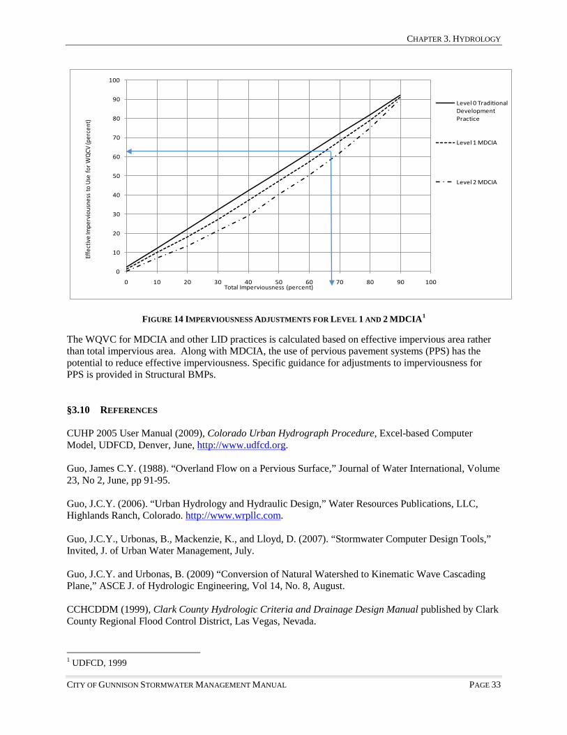
CHAPTER 3. HYDROLOGY
CITY OF GUNNISON STORMWATER MANAGEMENT MANUAL PAGE 33
0
10
20
30
40
50
60
70
80
90
100
0 10 20 30 40 50 60 70 80 90 100
Effe
ctiv
e Im
perv
ious
ness
to U
se fo
r WQ
CV (p
erce
nt)
Total Imperviousness (percent)
Level 0 Traditional Development Practice
Level 1 MDCIA
Level 2 MDCIA
FIGURE 14 IMPERVIOUSNESS ADJUSTMENTS FOR LEVEL 1 AND 2 MDCIA1
The WQVC for MDCIA and other LID practices is calculated based on effective impervious area rather than total impervious area. Along with MDCIA, the use of pervious pavement systems (PPS) has the potential to reduce effective imperviousness. Specific guidance for adjustments to imperviousness for PPS is provided in Structural BMPs.
§3.10 REFERENCES CUHP 2005 User Manual (2009), Colorado Urban Hydrograph Procedure, Excel-based Computer Model, UDFCD, Denver, June, http://www.udfcd.org. Guo, James C.Y. (1988). “Overland Flow on a Pervious Surface,” Journal of Water International, Volume 23, No 2, June, pp 91-95. Guo, J.C.Y. (2006). “Urban Hydrology and Hydraulic Design,” Water Resources Publications, LLC, Highlands Ranch, Colorado. http://www.wrpllc.com. Guo, J.C.Y., Urbonas, B., Mackenzie, K., and Lloyd, D. (2007). “Stormwater Computer Design Tools,” Invited, J. of Urban Water Management, July. Guo, J.C.Y. and Urbonas, B. (2009) “Conversion of Natural Watershed to Kinematic Wave Cascading Plane,” ASCE J. of Hydrologic Engineering, Vol 14, No. 8, August. CCHCDDM (1999), Clark County Hydrologic Criteria and Drainage Design Manual published by Clark County Regional Flood Control District, Las Vegas, Nevada.
1 UDFCD, 1999

CHAPTER 3. HYDROLOGY
PAGE 34 CITY OF GUNNISON STORMWATER MANAGEMENT MANUAL
Kuichling, E. (1889). “The Relation between Rainfall and the Discharge of Sewers in Populous Districts,” Trans. ASCE, Vol 20, pp 1-56. McCuen, R. (1982). “A Guide to Hydrologic Analysis Using SCS Methods,” Prentice-Hall, Inc., Englewood Cliffs, New Jersey. McCuen, R.H., Wong, S.L., and Rawls W.J. (1984). “Estimating Urban Time of Concentration,” J of Hydraulic Engineering, ASCE, Vol. 110, No. 7, July. Rossman, L (2005). Stormwater Management Model User’s Manual, Version 5.0. United States Environmental Protection Agency, Water Supply and Water Resources Division, National Risk Management Laboratory, Cincinnati, OH. Sherman, L.K. (1932). “Streamflow from Rainfall by the Unitgraph Method,” Eng. News—Rec., Vol. 108, pp 501-505. Snyder, F.F. (1938). “Synthetic Unit Graphs,” Trans. AGU, Vol. 19, pp 447-454. Urban Highway Storm Drainage Model. (1983). “Inlet Design Program,” Vol. 3, Federal Highway Administration, Report No. FHWA/RD-83/043, December. Soil Conservation Service (SCS) 1983. Soils of Colorado: Loss Factors and Erodability Hydrologic Groupings. United States Department of Agriculture, SCS. UDFCD (2001). Urban Stormwater Drainage Criteria Manual, Volumes 1 and 2, UDFCD, Denver, Colorado.

CHAPTER 4. STREET DRAINAGE
CITY OF GUNNISON STORMWATER MANAGEMENT MANUAL PAGE 35
Chapter 4 Street Drainage
§4.0 PURPOSE This chapter summarizes the procedures for street drainage system designs, including street hydraulic allowable capacity, street inlet sizing, and storm sewer design and flow analyses. The design methods presented in this chapter are referenced to the Hydraulic Engineering Circulation 22 published by the Federal Highway Administration (FHA HEC22) and Chapter 6 in the Urban Stormwater Drainage Criteria Manual (USWDCM, revised 2008, UDFCD). §4.1 DESIGN STORMS A street drainage system consists of minor and major systems. While street inlets and sewers are designed to intercept minor storm events, street gutters and roadside swales are part of the major drainage system that is capable of passing the storm runoff from major storms. During a major storm event, the excess stormwater will accumulate in and be carried through the street gutters. Wherever the spread or pooling of water on the street exceeds the allowable spread, an inlet must be placed. Table 4-1 presents the City’s requirements established for the level of protection in terms of storm return periods for the minor and major street drainage systems. §4.2 STREET CLASSIFICATIONS Alleys in Gunnison are approximately 20 feet wide. They are typically paved in the residential areas and commercial areas. Local and sub-local streets in the City of Gunnison are designed to provide traffic service for residential areas. They may have stop signs and are characterized by two moving traffic lanes that are 12-feet wide in each direction and generally on-street parking is included in the street. The street cross-section is symmetrical to the street crown with a transverse slope across the traffic lanes ranging from 2 to 3.5 percent, increasing to 4 percent across the parking lane which is 8 feet wide. A Sub-Local Street is a narrow street that may be used in low density residential zone districts. Sub-Local Street may have side ditches or swales to collect the street runoff without curbs and gutters. Minor collector streets in the City of Gunnison are designed to provide service to residential areas and to serve the main thoroughfares of the city. An example of a minor/collector is Denver Avenue. The cross section of a residential/collector street is similar to a local street and includes a parking lane – width is 8 feet for parallel parking. Arterial and major collector streets in the City of Gunnison are designed to provide service to business areas. These street classifications provide two moving traffic lanes of a minimum of 12 feet wide in each direction. The street cross-section is symmetrical to the street crown with a transverse slope varied from two to four percent across the traffic lanes. Parking lanes are adjacent to the curbs and gutters. Ideally, there are sufficient landscaping strips between sidewalks and parking lanes. Cross-section drawings of standard street sections can be found in the City of Gunnison Land Development Code. §4.3 CONSTRUCTION STANDARDS The following section sets forth a series of equations to define the geometric street design. It also includes some typical cut-sheet designs for some street drainage facilities. Note that the material specifications and installation design standards are not set forth herein, but are found in Section 700 of the City of Gunnison Construction Standards. If there are conflicts between statements and design directions found in this

CHAPTER 4. STREET DRAINAGE
PAGE 36 CITY OF GUNNISON STORMWATER MANAGEMENT MANUAL
Stormwater Manual and the City of Gunnison Construction Standards, the City Engineer shall determine the design procedure to be utilized. §4.4 DESIGN CONSIDERATIONS FOR STREET DRAINAGE All street gutters or bar ditches in the City of Gunnison must be able to handle the minor event storm without overtopping the curb(s) or swale(s) and without inundating the sidewalks or crowns of the road. Residential and commercial streets must maintain at least one-lane width in the middle of the street for each traffic direction free from stormwater to allow for emergency use. The major storm runoff on the street must be assessed to determine the potential for flooding and public safety.
TABLE 4-1 MINOR AND MAJOR STREET SYSTEMS DESIGN RETURN PERIODS AND ALLOWABLE SPREAD Drainage System Level of Protection (Return Period in Years)
Arterial and Major Collector
Minor Collector Street
Sub-Local and Local Street Alley
Minor System 10 10 5 5 Maximum Water Spread during a Minor Event
No curb overtopping. Flow spread must leave at least one lane free from water for both traffic directions
No curb overtopping. Flow spread must leave at least one lane free from water for both traffic directions
Flow may spread to crown of street
The depth of water cannot exceed 12 inches in the low point or cause inundation of adjacent buildings
Major System 100 100 100 100 Maximum Water Depth during a Major Event
The depth of water should not exceed the street crown to allow operation of emergency vehicles. The depth of water over the gutter flow line should not exceed 12 inches or cause inundation of adjacent buildings
The depth of water over the gutter flow line should not exceed 12 inches or cause inundation of adjacent buildings
The depth of water over the gutter flow line should not exceed 12 inches or cause inundation of adjacent buildings
The depth of cannot exceed 12 inches in the low point or cause inundation of adjacent buildings
It is the responsibility of the property owner to protect their property from street drainage and to maintain the street’s ability to carry floodwaters. Building structures should be established with a vertical grade 6 inches above the top of the curb or 12 inches from the street surface to maintain the appropriate capacities of the streets. Since it is more economical to continue accumulating gutter flow across a street intersection, not every street corner needs an inlet unless the water spread will be wider than what is allowable. A cross flow is allowed at a street intersection if it does not create hazards to traffic movement and pedestrians. The dimension of a cross pan is illustrated in Figure 15.

CHAPTER 4. STREET DRAINAGE
CITY OF GUNNISON STORMWATER MANAGEMENT MANUAL PAGE 37
FIGURE 15 CROSS PAN
§4.5 STREET-SIDE SWALE (BAR DITCHES) Swales are designed to collect runoff from streets and transport stormwater to the nearest inlet or major waterway. Curbless streets with swales are encouraged where possible because of the systems’ effectiveness in reducing runoff and pollutant loadings. More information about the water quality benefits and the design of road side swales can be found in Chapter 7 Stormwater Quality.
FIGURE 16 TYPICAL SWALE CROSS-SECTION
To calculate the capacity of a swale use the following set of equations:
EQUATION 4-1 CAPACITY OF A SWALE
𝑇 = (𝑍1 + 𝑍2)𝑌
EQUATION 4-2 CAPACITY OF A SWALE
𝐴 =12
(𝑇 + 𝐵)
EQUATION 4-3 CAPACITY OF A SWALE

CHAPTER 4. STREET DRAINAGE
PAGE 38 CITY OF GUNNISON STORMWATER MANAGEMENT MANUAL
𝑃 = √1 + 𝑍12 + √1 + 𝑍22 + 𝐵
EQUATION 4-4 CAPACITY OF A SWALE
𝑅 = 𝐴𝑃
EQUATION 4-5 CAPACITY OF A SWALE
𝑄 = 1.489𝑁
𝐴53 𝑃−
53�𝑆
𝑜 Where:
𝑍1 = Left Side Slope
𝑍2 = Right Side Slope 𝐵 = Bottom Width (ft)
𝑄 = Flow Rate (cfs)
𝑁 = Manning′s Roughness Coefficient
𝐴 = Flow Area (ft2) 𝑇 = top Width (ft)
𝑅 = Hydraulic Radius (ft) 𝑃 = Wetted Perimeter (ft)
𝑆𝑜 = Longitudinal Slope �ftft�
Considering public safety and maintenance, swales shall be designed with limitations on flow velocity, depth, and cross-slope geometries. The following limitations shall apply to street-side swales:
• Maximum 100-year flow velocity = 7.0 ft/sec to avoid severe erosion • Maximum 100-year depth = 2 feet • Maximum side slope for each side = 4H:1V to stabilize the banks
Under no circumstances shall a street-side swale have a longitudinal slope steeper than that of the adjacent street. Use proper linings or grade control checks to satisfy the design criteria. §4.6 GUTTER DESIGN
4.6.1 Street Gutter Flow. The street hydraulic capacity for a local or collector street in the City of Gunnison is dictated by the allowable water depth (D) in the gutter or the allowable water spread across the traffic lane. In practice, a gutter depression Ds, of two inches is introduced at the street curb. The dimensions of a curb-gutter unit are illustrated in Figure 17.

CHAPTER 4. STREET DRAINAGE
CITY OF GUNNISON STORMWATER MANAGEMENT MANUAL PAGE 39
FIGURE 17 CATCH-TYPE CURB AND GUTTER UNIT
Figure 18 illustrates a typical street and gutter cross section. Stormwater flow carried in a street gutter can be divided into gutter flow, Qw, and side flow, Qx. The gutter flow is the amount of flow carried within the gutter width, W, and the side flow is the amount of flow carried by the water spread, Tx, encroaching into the traffic lanes.
Where: W = gutter width (2.5 ft for the City of Gunnison) Ds = gutter depression (2 inches) Sx = street transverse slope (2% or 4% for the City of Gunnison) Sw = gutter cross slope D = water depth at curb face = Y + Ds Ts = water spread in feet for water depth, D, in the gutter Tx = side flow width Qx = side flow in cfs Qw = gutter flow in cfs n = surface roughness coefficient of 0.016
FIGURE 18 STREET AND GUTTER CROSS-SECTION FOR A LOCAL OR COLLECTOR STREET (NOT DRAWN TO SCALE)

CHAPTER 4. STREET DRAINAGE
PAGE 40 CITY OF GUNNISON STORMWATER MANAGEMENT MANUAL
The minimum gutter grade shall be 0.75%. The minimum cross-slope on all streets shall be 2.0% and may vary from 2.0% to 4.0%. The street and gutter section having the most restrictive capacity (steepest cross-slope) shall be used for design. Applying the open channel flow theory to the gutter and side flow yields:
EQUATION 4-6 OPEN CHANNEL FLOW THEORY FOR GUTTER AND SIDE FLOWS
Qx = 0.56𝑛
𝑆𝑥1.67𝑇𝑥2.67√𝑆𝑜
Qx = 0.56𝑛
𝑆𝑤1.67[𝑇𝑠2.67 − (Ts−W)2.67]√𝑆𝑜
The total flow, Q, on the street is the sum as:
Q = Qx + Qw
The flow cross sectional area for a composite street is calculated as:
EQUATION 4-7 FLOW CROSS SECTIONAL AREA FOR COMPOSITE STREET
A = 𝑌𝑇+𝑊𝐷𝑠2
4.6.2 Allowable Street Hydraulic Capacity. Street hydraulic capacity is dictated by the allowable gutter depth or the allowable water spread across the traffic lanes, whichever is smaller. In addition to water flow depth and spread, water flowing on a steep street can develop a high speed and imposes a significant impingement force on vehicles and pedestrians. As recommended (USWDCM 2001, UDFCD), the street gutter-full capacity is subject to flow reduction. Using the product of flow velocity and water depth, flow reduction factors are derived for both minor and major storm events for the City of Gunnison. The flow reduction factor is reduced as the street grade increases. (Did you intend to delete the equations for Allowable Street Hydraulic Capacity (ASCH), which is referenced later?) §4.7 INLET FUNCTIONS Stormwater inlets are a vital component of the urban stormwater collection and conveyance system. Inlets collect excess stormwater from the street, transition the flow into storm sewers, and can provide maintenance access to the storm sewer system.
4.7.1 Inlets. The spacing between two adjacent inlets is governed by the Allowable Street Hydraulic Capacity (ASHC). Street inlets are spaced so the design flow on the street is close to, but not exceeding, the ASHC for the minor storm event. There are four major types of inlets: grate, curb opening, combination, and slotted. Standard grate types are noted in Figure 19.

CHAPTER 4. STREET DRAINAGE
CITY OF GUNNISON STORMWATER MANAGEMENT MANUAL PAGE 41
4.7.2 Inlet Clogging. Inlets are subject to clogging by urban debris, which can vary by location and season. A clogging factor of 50 percent is used for a single grate and 12 percent for a single curb opening inlet. The clogging factor declines as the number of inlet units increases. Table 4-2 lists the clogging factors for inlets with multiple units.
The interception capability of an on-grade inlet is proportional to the inlet wetted length, and an in-sump inlet is proportional to the inlet opening area. The effective length of an on-grade inlet is calculated as:
EQUATION 4-8 EFFECTIVE LENGTH OF AN ON-GRADE INLET
𝐿𝑒 = �1 –𝐶𝑔�𝐿 In which L = total wetted length, Cg = clogging factor selected for the number of inlet units, and Le = effective (unclogged) length. Similarly, the effective opening area of an in-sump inlet is calculated as:
EQUATION 4-9 EFFECTIVE OPENING AREA OF AN IN-SUMP INLET
𝐴𝑒 = �1 –𝐶𝑔�𝐴 In which: A = total opening area, and Ae = unclogged opening area.
TABLE 4-2 CLOGGING FACTORS FOR INLET DESIGN NUMBER OF INLET UNITS CLOGGING FACTOR – CURB-
OPENING INLET CLOGGING FACTOR – GRATE
INLET 1 0.12 0.50 2 0.08 0.38 3 0.05 0.29
>4 0.04 0.23
FIGURE 19 STANDARD CURB INLETS

CHAPTER 4. STREET DRAINAGE
PAGE 42 CITY OF GUNNISON STORMWATER MANAGEMENT MANUAL
4.7.3 Design Flow on Street. Often an on-grade inlet is designed to capture 70 to 90 percent of the street flow. The by-pass flow will be carried over to the next downstream inlet. The design flow, Qs, at an inlet location is the sum of the local flow, Qp, contributed from the local area and the carry-over flow, Qco, from the immediately upstream inlet.
EQUATION 4-10 DESIGN FLOW ON STREET
Qx = Qp + Qco
Example for Street Design Flow. Use the Rational Method to find the 10-year local design flow to be 10.5 cfs. With a carryover flow of 1.2 cfs (not captured from the upstream inlet), the design flow is calculated as:
𝑄𝑠 = 10.5 + 1.2 = 11.7 cfs 4.7.4 On-Grade Grate Inlet. Stormwater carried in the street includes the gutter flow that is carried within the gutter width, and the side flow that is spread into the traffic lanes. In general, the gutter flow within the gutter width can be completely intercepted by the inlet. The interception percentage, Rx, of the side flow is estimated as:
EQUATION 4-11 INTERCEPTION PERCENTAGE OF THE SIDE FLOW FOR ON-GRADE GRATE INLET
𝑅𝑥 = 1
�1 + 0.15𝑉1.8
𝑆𝑥𝐿𝑒2.3 �
As a result, the total interception capacity, Qi, for the grate inlet is equal to:
EQUATION 4-12 TOTAL INTERCEPTION CAPACITY FOR ON-GRADE GRATE INLET
𝑄𝑖 = 𝑄𝑤 + 𝑅𝑥𝑄𝑥
The carry-over flow, Qco, is the difference between Qx and Qi, as:
EQUATION 4-13 CARRY-OVER FLOW FOR AN ON-GRADE GRATE INLET
𝑄𝑐𝑜 = 𝑄𝑠 − 𝑄𝑖
4.7.5 In-Sump Grate Inlet. A grate inlet in a sump can operate like a weir under a shallow water depth. Its weir-flow capacity is estimated as:
EQUATION 4-14 WEIR-FLOW CAPACITY FOR AN IN-SUMP GRATE INLET
𝑄𝑤 = 𝐶𝑤𝑃𝑒𝑌𝑠 1.5
In which Qw = weir-flow capacity in cfs, Cw = weir coefficient such as 3.0 for feet-second units, Ys = water depth in ft, and Pe = effective weir length in feet around the inlet grate defined as:
EQUATION 4-15 WEIR LENGTH AROUND IN-SUMP GRATE INLET
𝑃𝑒 = (1 − 𝐶𝑔) 𝑃

CHAPTER 4. STREET DRAINAGE
CITY OF GUNNISON STORMWATER MANAGEMENT MANUAL PAGE 43
When a grate is submerged and operates like an orifice, its orifice-flow capacity is estimated as:
EQUATION 4-16 ORIFICE-FLOW CAPACITY FOR IN-SUMP GRATE INLET
𝑄𝑜 = 𝐶𝑜𝐴𝑒�2𝑔𝑌𝑠
𝐴𝑒 = (1 − 𝐶𝑔) 𝑚 𝑊𝑜𝐿𝑜
In which Co = orifice coefficient (this coefficient relates the wetted perimeter of the grate, P, to the effective perimeter Pe, that acts as a weir; the recommended value for Co for most applications is 0.65), g = gravitational acceleration (32.2 ft/sec2), Wo = grate width in ft, Lo = grate length in ft, and m = area opening ratio on the grate. The transition between weir flow and orifice flow is not clearly understood. Theoretically, the change in the hydraulic performance of a grate occurs at a depth where the weir rating curve intersects the orifice rating curve. In practice, for a specified water depth, the interception capacity of an inlet grate is the smaller of Qw and Qo.
4.7.6 On-Grade Curb Opening Inlet. To install a curb opening inlet on a continuous grade, the required curb opening length, Lt, for complete (100%) interception of the design storm runoff, Qs, on the street is computed by:
EQUATION 4-17 INTERCEPTION OF DESIGN STORM RUNOFF FOR ON-GRADE CURB OPENING INLET
Lt = 0.60Q0.42 So0.30 �1
nSe�0.6
𝑆𝑒 = 𝑆𝑥 + 𝑆𝑤 𝑄𝑤𝑄𝑠
In which Lt = required length for 100% interception, So = street longitudinal slope, n = Manning’s roughness of 0.016, and Se = equivalent transverse street slope. The curb-opening inlet shall have a length less than, but close to, Lt. The interception capacity of a curb-opening inlet is calculated as:
EQUATION 4-18 REQUIRED LENGTH FOR 100% INTERCEPTION
FOR ON-GRADE CURB OPENING INLET
𝑄𝑖 = 𝑄 �1 − �1 − 𝐿𝑒𝐿𝑡�1.80
�
In which, Qi = inlet capacity, and Le = effective length of the curb opening inlet.
4.7.7 In-Sump Curb Opening Inlet. Referring to Figure 20, a curb-opening inlet in a sump operates like a weir. Its interception capacity is estimated as:
EQUATION 4-19 INTERCEPTION CAPACITY OF AN IN-SUMP CURB-OPENING INLET
𝑄𝑤 = 𝐶𝑤𝑃𝑒𝑌𝑠1.5 𝑃𝑒 = �1 − 𝐶𝑔��𝐿 + 𝑘𝑊𝑝� + 2𝑊

CHAPTER 4. STREET DRAINAGE
PAGE 44 CITY OF GUNNISON STORMWATER MANAGEMENT MANUAL
In which Pe = effective weir length around the depression pan in front of the curb opening inlet, Wp = width of depressed pan, and k = 1.8 for two sides of the pan in Figure 20. When the water gets deeper, a curb opening inlet operates like an orifice that can be modeled as:
EQUATION 4-20 MODELING FOR IN-SUMP CURB-OPENING INLET
𝑄𝑜 = 𝐶𝑜𝐴𝑒�2𝑔(𝑌𝑠 − 𝑌𝑐)
In which Ys = water depth, Yc = center of opening area above the ground, H = height of opening area, L = width of opening area. The center of the curb opening area is the vertical distance above the flow line. It is important that the thickness of the concrete covered be included in the calculation of the depression of the curb opening.
It is not well understood how an in-sump curb opening inlet switches form weir to orifice flow. In practice, for a specified water depth, the interception capacity of an in-sump inlet is dictated by the smaller value of the weir or the orifice flows.
4.7.8 Slotted Inlet. A slotted inlet is similar hydraulically to a curb-opening inlet. As a result, design formulas developed for curb-opening inlets are also applicable to slotted drain inlets. Trenches are often used as a slotted inlet. The interception capacity of a trench is similar to the slotted inlet while the conveyance capacity of a trench is calculated using the ditch flow formulas, Equation 4-1 through Equation 4-5.
FIGURE 21 SLOTTED INLET
4.7.9 Combination Inlet. A combination inlet, shown in Figure 22, is formed with a curb opening and a grate inlet. If one inlet is clogged the other can still function. Empirical formulas for sizing an inlet were developed under the assumption that each inlet operates independently, although the interference between the grate inlet and the curb opening inlet in a combination inlet has not been fully investigated
FIGURE 20 EXAMPLE OF CURB OPENING INLET IN SUMP

CHAPTER 4. STREET DRAINAGE
CITY OF GUNNISON STORMWATER MANAGEMENT MANUAL PAGE 45
yet. The assumption of independent operation implies that the curb-opening inlet is placed immediately downstream of the grate inlet. In theory, the capacity of a combination inlet is less than the sum of the interception for both inlets. To be conservative, the capacity of a combination inlet is assumed to be the higher value of either the grate or the curb-opening inlet when the water depth is shallow (<6 inches) (Guo, 1996). The assumption that both inlets can work independently may be justified when the water depth is greater than the curb-opening height.
FIGURE 22 ASSUMPTIONS REGARDING FLOW INTERCEPTION BY A COMBINATION INLET
§4.8 CULVERT CONSTRUCTION STANDARDS 4.8.1 Construction Material. Culverts shall be designed and built pursuant to the adopted City of Gunnison Construction Standards. In rural areas, corrugated metal pipe culverts in round or arch cross sections may be accepted on a case-by-case basis. 4.8.2 Minimum Pipe Size. The minimum pipe size for culverts within a public right-of-way (ROW) shall be 24 inches diameter round, or shall have a minimum cross sectional area of 3.3 ft2 for arch or elliptical shapes, except private driveway culverts, which may have a minimum diameter of 18 inches. Box culverts shall be as tall as physically possible, but shall not have less than a 3-foot high inside dimension. 4.8.3 Alignment. The alignment of the culvert with respect to the natural channel is very important for proper hydraulic performance. Culverts may pass beneath the roadway normal to the centerline or they may pass at an angle (skewed). Culverts shall be aligned with the natural channel. This reduces inlet and outlet transition problems. Some instances may warrant the modification of the natural channel alignment to reduce necessary culvert length. Modifications to the channel alignment or profile affect the natural stability of the channel and proposed modifications shall be thoroughly investigated. In many cases where the channel alignment is modified, grade control or drop structures are needed to achieve stable channel slopes upstream or downstream of the culvert. Improper culvert alignment and poorly designed outlet protection may cause erosion to adjacent properties, increased instability of the channel and sedimentation accumulation in the culvert. 4.8.4 Minimum Cover. The vertical alignment of roadways relative to the natural existing channel profile may define the maximum culvert diameter/height that can be used. Low vertical clearance may require the use of elliptical or arched culverts, or the use of a multiple-barrel culvert system. Culverts shall have a minimum of 1.5 feet of cover above the top of the pipe. Approval by the City Engineer will be required for culverts with less than 1.5 feet of subgrade cover. 4.8.5 Multiple-Barrel Culverts. If the available fill height limits the size of culvert necessary to convey the flood flow, multiple culverts can be used. The number of separate culvert barrels shall be kept

CHAPTER 4. STREET DRAINAGE
PAGE 46 CITY OF GUNNISON STORMWATER MANAGEMENT MANUAL
to a minimum. If each barrel of a multiple-barrel culvert is of the same type and size and constructed such that all hydraulic parameters are equal, the total flow shall be assumed to be equally divided among each of the barrels. 4.8.6 Trash Racks/Safety Grates. The use of trash/safety racks at inlets to culverts and long underground pipes is assessed on a case-by-case basis. Alternatives to limit access or catch debris upstream of the culvert should be thoroughly investigated prior to considering improvements on the culvert inlet. During the heavy runoff, trash racks often become clogged and the culvert is rendered ineffective. In general, a trash/safety rack will not be needed if one can clearly “see daylight” from one side of the culvert to the other, if the culvert is of sufficient size to pass a 48" diameter object and if the outlet is not likely to trap or injure a person. By contrast, at entrances to longer culverts and long underground pipes and for culverts not meeting the above-stated tests, a trash/safety rack may be necessary. Trash racks or grates used to limit access will not be allowed on the downstream ends of culvert or pipe outlets. Table 4-3 provides guidelines when to use, and when not to use a trash/safety rack.
TABLE 4-3 USE OF TRASH/SAFETY RACKS
USE A TRASH/SAFETY RACK WHEN: DO NOT USE A TRASH/SAFETY RACK WHEN:
• Debris may cause plugging of the culvert inlet • A bend, drop, or obstruction is located in the culvert • An unsafe condition is located at the outlet • Culvert is smaller than 48 inches in diameter • Culvert is longer than 200 feet
• Daylight can be seen through the culvert
• At culvert or storm sewer outlets
If a trash/safety grate is necessary, the following criteria shall be met: 1. rack shall be designed for full hydrostatic load 2. minimum grate area shall be four times pipe opening area 3. maximum velocity through rack shall be 2 fps 4. the rack slope shall be 3:1 maximum 5. maximum bar spacing of 4 ½ to 5 inches 6. bars shall be parallel to flow 7. provide a clear opening of 9-12 inches at the bottom 8. maintenance requirements are addressed by hinging the rack or providing a method for equipment
removal of the rack 9. maintenance access to the underside of the rack shall be provided 10. a separate rack upstream of the structure is an acceptable alternative 11. collapsible racks are discouraged
4.8.7 Inlets and Outlets. Culvert inlets will require erosion protection where stable channel velocities are exceeded. If needed, riprap erosion protection shall be designed according to the procedures outlined in the Major Drainage section of the UDFCD Manual. In addition, culvert outlets are discussed in Chapter 5 of this Manual. §4.9 DRIVEWAY CULVERT STANDARDS 4.9.1 Applicable Criteria. The requirements in this section apply to developments where the roadside swale has depth. Urban roadside swales, used to incorporate the MDCIA concept into a development, are treated in a different manner.
CHAPTER 4. STREET DRAINAGE
CITY OF GUNNISON STORMWATER MANAGEMENT MANUAL PAGE 47
4.9.2 Construction Material. Residential driveway culverts shall be constructed pursuant to the material specifications and installation standards defined in the City of Gunnison Construction Standards. 4.9.3 Minimum Size. Residential driveway culverts for new developments or subdivisions shall be sized to pass the flow capacity without overtopping the driveway. The minimum size for driveway culverts shall be 18 inches in diameter for round pipe or shall have a minimum cross sectional area of 1.8 square feet for arch or elliptical shapes. 4.9.4 Minimum Cover. Residential driveway culverts shall be provided with the minimum cover recommended by the pipe structural design requirements, or 1-foot, whichever is greater. 4.9.5 Culvert End Treatments. Driveway culverts shall be provided with end treatments on the upstream and downstream ends of the culvert to protect and help maintain the integrity of the culvert opening. Flared end sections or headwalls and/or wingwalls are acceptable end treatments. 4.9.6 Minimum Slope. A minimum slope shall be provided to achieve the minimum velocities or a minimum slope of 2 percent is required, whichever is greater. 4.9.7 Design and Construction of Driveway Culverts. Additional information must be included in the drainage report and on the construction drawings for new subdivisions, where the use of roadside swales and driveway culverts is proposed. Culverts shall be sized for each lot in the subdivision drainage report, based on the tributary area at the downstream lot line. The construction drawings shall include information regarding maximum conveyance volume, sizes, materials, locations, lengths, grades, and end treatments for all driveway culverts. Typical driveway crossing/culvert details shall be included in the construction drawings. In general, typical roadside ditch sections do not have adequate depth to accommodate driveway culvert installations, which meet the criteria outlined in this section. §4.10 STORM SEWERS The storm sewer system is comprised of inlets, pipes, manholes, bends, outlets, and other appurtenances. The stormwater passes through these components and is discharged into a downstream water quality enhancement facility before draining into a natural water body. The plan layout and vertical profile of a storm sewer system are governed by the following factors as: • street alignment for the sewer line • street inlet placement • existing utility locations • sewer system outfall location and tailwater elevation 4.10.1 Manholes. Manholes and junctions are used in storm sewer systems to provide a hydraulically efficient transition at alignment changes along a sewer line manhole shall be located at any of the following points: • where the pipe size changes • where the direction of sewer line changes • where the invert grades along the sewers change • where drops are added to the vertical profile • in conjunction with all laterals • where the lateral is not easily accessible for maintenance form the inlet • where the spacing between manholes exceeds 400 feet
4.10.2 Design Procedure and Constraints. Storm sewer system design requires basic data in the proposed service area, including topography, drainage boundaries, soil types, and locations of any

CHAPTER 4. STREET DRAINAGE
PAGE 48 CITY OF GUNNISON STORMWATER MANAGEMENT MANUAL
existing storm sewers, inlets, and manholes. In addition, identification of the type and location of other utilities is necessary. Design of a stormwater system begins with the placement of inlets and manholes. The vertical profile for the proposed sewer line can be approximated using the street profile as a reference. The sewer crowns may be set 7 feet or greater below the ground surface. Storm sewers are sized from the most upstream manhole to the system exit. The longest flow time among all incoming flow paths to the manhole shall be used to calculate the design rainfall intensity. The Rational method is recommended to estimate the peak flow at the manhole and the Manning’s formula, Equation 4-1 through Equation 4-5, is suitable to size the outgoing sewer from the manhole. After all mains are sized by open channel flow under the normal flow condition, the system is further subject to a performance evaluation under the normal flow condition, and under a given tailwater at the system exits. The energy and hydraulic grade lines will predict if any manholes in the sewer system are surcharged. The storm sewer design can be finalized by continuously adjusting sewer sizes and manhole drops until all the design criteria and constraints are satisfied, including: • permissible flow velocity in a sewer between 2 and 18 fps for the selected pipe material and slope; • minimum earth coverage of 7 feet, for the cold climate in the Gunnison area; • minimum sewer diameter of 18 inches for sewer trunks and 15 inches for lateral lines; • minimum manhole drop of 0.20 foot; and, • maximum manhole spacing of 400 feet. A sewer shall be sized so that the normal design depth does not exceed 80% of the diameter of a circular pipe or the height of a box sewer to accommodate back-water effects. Decrease in sewer size due to steep invert slope or smooth pipe roughness must be avoided. 4.10.3 Design Flow at Manhole. A manhole is treated as a design point where the system flow from the upstream tributary area is combined with the local flows from the local tributary areas. There are two ways to compute the design at a manhole. Design Flow Using Rational Method. To model the accumulation of flows along the storm sewer line, all manholes and sewers are converted into nodes and links. Sewer sizing charts from the most upstream manhole. At the n-th node, the local area is combined with the accumulated area in the system as:
EQUATION 4-21 STORM SEWER SIZING
(𝐴𝑒) 𝑛 = 𝐶𝑛𝐴𝑛 + � 𝐶𝑖𝐴𝑖
𝑖=𝑛−1
𝑖=1
The accumulated travel time through the storm sewer line is:
EQUATION 4-22 ACCUMULATED TRAVEL TIME THROUGH STORM SEWER
(𝑇𝑐)𝑛 = (𝑇𝑐)𝑛−1 + 𝐿𝑛
60𝑉𝑛
In which Ae = effective contributing area in acres, Tc = accumulated time of concentration in minutes, L = sewer length in feet, V = sewer flow velocity in fps,

CHAPTER 4. STREET DRAINAGE
CITY OF GUNNISON STORMWATER MANAGEMENT MANUAL PAGE 49
I = i-th node upstream of the design point, and n = n-th node at the design point. Set the design rainfall duration equal to Tc to calculate the peak flow using the Rational Method.
Design Flow with Known Local Flow. This approach can be used in the case that the local flow at the manhole is specified by the hydrologic report, or provided as a quantified off-site input to the storm sewer system. The inherent time of concentration, Ta, for this know local flow, Qa, can be calculated using the local area Aa, and runoff coefficient, Ca, as:
EQUATION 4-23 INHERENT TIME OF CONCENTRATION
𝑖 = 𝑄𝑎𝐶𝑎
= 10𝑃1
(10 + 𝑇𝑐) 0.789
Equation 4-23 will then be incorporated into the accumulation process of flow time through the sewer line for continuous peak flow calculations using the Rational Method.
4.10.4 Storm Sewer Sizing – Circular, Box, and Arch Pipes Circular Sewer Hydraulics. Equation can be applied to determine the minimum diameter, d, required to accommodate a design flow, Q, in a pipe flowing full under gravity (normal) flow conditions using Manning’s equation.
EQUATION 4-24 CIRCULAR SEWER HYDRAULICS
𝑑 = �𝑛𝑄𝑘�𝑆𝑜
� 38
Where: Q = design flow in cfs, So = conduit invert slope in ft/ft, d = hydraulically required circular diameter in feet (full flow assumed), and K = 0.462 for feet-second units. The calculated pipe size is often not commercially available. As a result, the next larger commercially available pipe size shall be used. This will result in partially-full flow. To determine the depth for partially-full flow (to check against 80% criterion under normal flow conditions), the following procedure can be used:
1. Calculate Qfull for the actual pipe diameter using Manning’s equation, 2. Calculate the ratio of Qdesign/Qfull, 3. Look up d/Dfull value corresponding to Qdesign/Qfull 4. Calculate depth, d = d/Dfull * pipe diameter
The nomograph or tabular procedure should be used for evaluating partially full flow conditions for larger commercially-available pipe.
Arch (Elliptical) Sewer Hydraulics. An elliptical or arch pipe is sometimes selected as a replacement for a circular pipe to accommodate other utilities or grading issues. The flow through an elliptical or arch pipe in Figure 23 is dictated by the cross-sectional geometry. An equivalent circular pipe may be used as an approximation in hydraulic computations.

CHAPTER 4. STREET DRAINAGE
PAGE 50 CITY OF GUNNISON STORMWATER MANAGEMENT MANUAL
The equivalent diameter is approximated by:
EQUATION 4-25 EQUIVALENT DIAMETER OF ELLIPTICAL SEWER
𝑑 = 0.5(𝐻 + 𝑊) Box Sewer Hydraulics. The width of the box sewer must be specified. The hydraulic calculation is to provide the flow depth. As illustrated in Figure 24, the hydraulic parameters in a box sewer are related to the flow depth as:
EQUATION 4-26 HYDRAULIC PARAMETERS IN A BOX SEWER
𝐴 = 𝐵𝑌 𝑃 = 2𝑌 + 𝐵
4.10.5 Sewer Energy and Hydraulic Grade Lines. The Energy Grade Line (EGL) represents the energy slope between the two adjacent manholes in a storm sewer system. A manhole may have multiple incoming sewers, but only one outgoing sewer. Each sewer and its upstream manhole form a sewer and manhole unit. The entire storm sewer system can be decomposed into a series of sewer and manhole units. Each unit has to satisfy the energy principle. The computation of Energy Grade Line (EGL) is a repetition of the energy balance process through each sewer and manhole unit.
EQUATION 4-27 SEWER ENERGY AND HYDRAULIC GRADE LINES
𝐻1 + 𝑉1
2
2𝑔= 𝐻2 +
𝑉2 2
2𝑔+ 𝐻𝑓 + 𝐻𝑚
W H
FIGURE 23 ELLIPTICAL SEWER
B Y
FIGURE 24 BOX SEWER

CHAPTER 4. STREET DRAINAGE
CITY OF GUNNISON STORMWATER MANAGEMENT MANUAL PAGE 51
Where H = water surface elevation at manhole, V = flow velocity through sewer, Hf = friction loss through the sewer pipe, and Hm = juncture losses at manhole. The subscript “1” represents the upstream manhole and “2” represents the downstream manhole.
The flow in a storm sewer pipe can be either, or a combination of: open channel flow, surcharged flow, or pressurized flow. When a free surface exists through the pipe length, open channel hydraulics shall be applied to the backwater surface profile computations. The friction loss through the sewer pipe is the cumulative head losses through the specified type of water surface profile. The sewer pipe carrying a subcritical flow may have an M-1 water surface profile if the downstream manhole is almost surcharged or an M-w water surface profile if the downstream manhole is not surcharged. On the other hand, a pipe carrying a supercritical flow may have an S-2 water surface profile if the downstream manhole is not submerged. Otherwise, a hydraulic jump may be expected. When the downstream sewer crown is submerged to a degree that the entire sewer pipe is under the hydraulic grade line, the head loss for this flowing-full condition is estimated by pressure flow hydraulics. When the downstream sewer crown is slightly submerged, the downstream end of the sewer pipe is surcharged, but the upstream end of the sewer pipe can remain as open channel flow. The head loss during surcharge flow depends on the flow regime. The head loss may involve a hydraulic jump for subcritical flow. The culvert hydraulic principles can be used to calculate both inlet and outlet control conditions, whichever is higher dominates the final result. §4.11 REFERENCES Akan, A.O. and R.J. Houghtalen. 2002. Urban Hydrology, Hydraulics, and Water Quality. Prentice Hall Upper Saddle River, NJ. Federal Highway Administration (FHWA). 1984. Drainage of Highway Pavements. Hydraulic Engineering Circular 12, Federal Highway Administration, Washington, DC. Federal Highway Administration (FHWA). 1996. Urban Drainage Design Manual. Hydraulic Engineering Circular 22, Federal Highway Administration, Washington, DC. Guo, J.C.Y. 1998a. Storm Sewer System Design and Flow Analysis Using the Personal Computer Model UDSEWER. Urban Drainage and Flood Control District. Denver, CO. Guo, J.C.Y. 1998b. Street Hydraulics and Inlet Sizing Using the Computer Model UDINLET. Urban Drainage and Flood Control District. Denver, CO. Guo, J.C.Y. 1999. Storm Water System Design. CE 5803, University of Colorado at Denver, CO. Guo, J.C.Y. 2000a. Design of Grate Inlets with a Clogging Factor. Advances in Environmental Research 4(3)181-186. Guo, J.C.Y. 200b. Street Storm Water Conveyance Capacity. Journal of Irrigation and Drainage Engineering 136(2)119-124. Guo, J.C.Y. 2000c. Street Storm Water Storage Capacity. Journal of Water Environment Research, Vol 27, No. 6. Sept/Oct.
CHAPTER 4. STREET DRAINAGE
PAGE 52 CITY OF GUNNISON STORMWATER MANAGEMENT MANUAL
Guo, James C.Y. 2006. Decay-based Clogging Factor for Curb Inlet Design, Vol 132, No. 11, ASCE J. of Hydraulic Engineering, November. USWDCM 2001. Urban Stormwater Design Criteria Manual, Volume 2, published by Urban Drainage and Flood Control District, Denver, CO. Wright-McLaughlin Engineers. 1969. Urban Storm Drainage Criteria Manual. Prepared for the Denver Regional Council of Governments. Urban Drainage and Flood Control District. Denver, CO.

CHAPTER 5. CONDUIT OUTLET STRUCTURES
CITY OF GUNNISON STORMWATER MANAGEMENT MANUAL PAGE 53
Chapter 5 Conduit Outlet Structures §5.0 INTRODUCTION This section addresses the design of culvert outlets, which are typically oriented in-line with the flow in a drainageway, and with storm sewer outlets, oriented perpendicular to the flow in a drainage channel or detention facility. This chapter contains references to the UDFCD Manual for design procedures applying to both of these outlet types. Outlets into forebay sedimentation traps of water quality basins are discussed in Chapter 7 .
5.0.1 Design Considerations. Conduit outlet structures are necessary to dissipate energy at culvert and storm sewer outlets and to provide a transition from the conduit to an open channel. A conduit outlet structure is comprised of an end section or headwall and wingwall, safety rail (if required), and a riprap or concrete structure to dissipate flow energy at the exit of the conduit. Occasionally, other hydraulic controls are located at culvert outlets.
§5.1 GENERAL LAYOUT INFORMATION 5.1.1 Inlet and Outlet Configuration. All conduits 54 inches in diameter and larger within the urbanized area of the city shall be designed with headwalls and wingwalls. Conduits 48 inches in diameter and smaller may use headwalls and wingwalls or flared end sections at the inlet and outlet. In rural areas of the city the use of flared end sections and rip rap stabilization in lieu of concrete headwalls and wingwalls shall be considered on a case-by-case basis. Appropriate justification and detailed design information will be required to be provided by the design engineer. 5.1.2 Safety Rails. Headwalls and wingwalls shall be provided with guardrails, handrails, or fencing in conformance with local building codes and roadway design safety requirements. Handrails shall be required in areas pursuant to the building codes adopted by the city. 5.1.3 Flared End Sections. Flared end sections shall not protrude from the embankment. Flared end sections require joint fasteners and toe walls at the outlet. Toe walls shall extend from the top of the vertical portion at the end of the flared end section to at least 3 feet below the invert. The width of the wall shall be as necessary to extend a 2:1 slope from the flared end section invert at the edge of the end section to the top of the wall (this slope shall be protected with riprap). See Figure 25 for an acceptable toe wall configuration. 5.1.4 All joint connections shall be mechanically locked with joint fasteners as shown in Figure 26. Joint fasteners shall be constructed consistent with the details provided in CDOT Standard Plan No. M-603-10. 5.1.5 Conduit Elevations Relative to Drainageways. In general, in-line culvert inlet and outlet elevations are to match drainageway invert elevations upstream and downstream. Outlets shall be provided with erosion protection per §5.2. Storm sewer outlets shall be set with their inverts 1- to 2-feet (2 feet for wetland channels) above the natural channel bottom and provided with erosion protection. The drop is to reduce backwater affects in the storm sewer due to sedimentation. If the existing drainageway has experienced degradation and the channel is incised, restoration improvements may raise the channel bottom back up to its former elevation. The design engineer shall determine the appropriate outlet elevations considering, at a minimum, the stability of the existing

CHAPTER 5. CONDUIT OUTLET STRUCTURES
PAGE 54 CITY OF GUNNISON STORMWATER MANAGEMENT MANUAL
channel and any potential stabilization or grade control improvements that would change the longitudinal grade or elevations along the channel. Inlet and outlet elevations shall be set based on field survey information, rather than topographic mapping generated from aerial photography.
FIGURE 25 CONCEPTUAL TOE WALL DETAIL

CHAPTER 5. CONDUIT OUTLET STRUCTURES
CITY OF GUNNISON STORMWATER MANAGEMENT MANUAL PAGE 55
FIGURE 26 PIPE OUTFALL JOINT RESTRAINT REQUIREMENTS

CHAPTER 5. CONDUIT OUTLET STRUCTURES
PAGE 56 CITY OF GUNNISON STORMWATER MANAGEMENT MANUAL
§5.2 CONDUIT OUTLET EROSION PROTECTION 5.2.1 Types of Erosion Protection. Erosion protection is required at the outlet of conduits to control scour. Erosion protection shall be designed for conduit outlets in accordance with Table 5-1. These are general guidelines only and are meant to supplement the UDFCD Manual. Other outlet protection options, including many specialized types of concrete outlet structures are available and may be used if approved by the City Engineer.
TABLE 5-1 EROSION PROTECTION AT CONDUIT OUTLETS
EROSION PROTECTION GUIDELINES
UDFCD Manual SECTION
USE FOR DO NOT USE FOR
Riprap Lining (5.3.1)
Section 7.0 of Major Drainage Volume 1
• Receiving channel on same line and grade
• Storm sewer and culvert outlets
• Velocities from 0-15 fps
• High tailwater • Fish passage
• Velocities above 15 fps
• Wetland channels
Low Tailwater Stilling Basin
(§5.3.2)
Section 3.4 of Hydraulic Structures
Volume 2
• Storm sewer and culvert outlets
• Velocities from 0-15 fps
• Low tailwater
• Velocities above 15 fps
• Confined receiving area
• Major drainage • Areas where
standing water is unacceptable
Concrete Impact Stilling Basin
(§5.3.3)
Section 3.2 of Hydraulic Structures
Volume 2
• Storm sewer outlets • Velocities over 15
fps • Low tailwater
• In-line culvert outlets
• High visibility areas
Concrete Baffle Chute (§5.3.4)
Section 3.3 of Hydraulic Structures
Volume 2
• Storm sewer outlets • Velocities over 5 fps • Low tailwater • Degrading channel
• In-line culvert outlets
• High debris potential • High visibility areas
Drop Structures Section 2.0 of Hydraulic Structures
Volume 2
• Wetland channels • Low rise box
culverts or small diameter pipes where plugging is possible
• Confined receiving area
• Fish passage
5.2.2 Selecting Type of Erosion Protection. Riprap protection downstream of culverts is appropriate for most situations where moderate outlet hydraulics govern. Where a storm sewer enters a drainageway at an approximate right angle, the designer will use a low tailwater basin. Drop structures or riprap lining are recommended for in-line culvert outlets on major drainageways. Prior to the selection of a concrete structure, the design engineer should evaluate techniques which are available to decrease outlet velocities to the point where a concrete stilling basin may not be necessary. Steep, high velocity conduits can be modified by providing a drop in a manhole and designing a larger
CHAPTER 5. CONDUIT OUTLET STRUCTURES
CITY OF GUNNISON STORMWATER MANAGEMENT MANUAL PAGE 57
diameter, flatter slope pipe from the manhole to the channel. This technique may also be used to reduce outlet velocities and the corresponding extents of riprap erosion protection. The use of concrete structures should be avoided when possible, and must be approved by the city prior to their use. If exit velocities are extremely high and turbulence at a conduit outlet is expected to be severe, and if space is especially limited, there are cases where a concrete stilling basin structure may be considered.
§5.3 DESIGN CRITERIA FOR CULVERT AND STORM SEWER OUTLET EROSION PROTECTION 5.3.1 Riprap Lining. Design procedures for riprap culvert outlet erosion protection are provided in the UDFCD Manual. Riprap protection is suggested for outlet Froude numbers up to 2.5 where the outlet of the conduit slope is parallel with the channel gradient and the conduit outlet invert is flush with the riprap channel protection. An additional thickness of riprap just downstream from the outlet is required to assure protection from extreme flow conditions that might precipitate rock movement in this region. Protection is required under the conduit barrel and an end slope is provided to accommodate degradation of the downstream channel. 5.3.2 Low Tailwater Riprap Basins. Low tailwater basins are required at the end of a storm sewer conduit or culvert, to dissipate the kinetic energy of the discharge protect against scouring at the channel bottom. Low tailwater is defined as being equal or less than one-third of the storm sewer diameter/height. 5.3.3 Concrete Impact Stilling Basin. The use of concrete stilling basins is discouraged where moderate outlet conditions exist, and where there are other options available which better fit the natural characteristic of the drainageway. The UDFCD Manual provides a standard design to allow drainage of the basin bottom during dry periods. 5.3.4 Concrete Baffle Chute. The use of concrete baffle chutes is discouraged where moderate outlet conditions exist, and where there are other options available which better fit the natural characteristic of the drainageway. A concrete baffle chute is normally used in situations where there is a very large conduit outfall, future channel degradation is expected, and there is a drop in grade between the culvert outlet and the channel invert. The designer shall provide riprap erosion protection along the downstream channel where a scour hole is undesirable. The UDFCD Manual provides some design and construction details for this type of basin.

CHAPTER 6. DETENTION
PAGE 58 CITY OF GUNNISON STORMWATER MANAGEMENT MANUAL
Chapter 6 Detention §6.0 OVERVIEW The City’s stormwater management goal is to mimic natural hydrology to the maximum extent possible. Treatment of the Water Quality Capture Volume (WQCV), discussed in Chapter 7 , provides infiltration or detention for many very small events (on the order of a 6-month to 1-year event), approximately 80 percent of the storms in Gunnison. A small portion of the runoff will be detained in the water quality treatment areas for larger events. The remaining runoff must be conveyed to the river safely and in a manner that doesn’t increase the flooding potential of downstream properties. Development will incorporate a pragmatic approach to detention – “do no more harm than previously,” which means that development and redevelopment are required to detain any increase in runoff from existing conditions. This chapter provides guidance to design stormwater flood control detention facilities. Topics discussed in this chapter include:
• types of detention facilities; • design considerations; • determination of allowable release; • design procedures; • methods for calculating detention volume requirements; • initial sizing for detention basin design; and • preliminary design and final refinement. §6.1 TYPES OF DETENTION BASINS The main objective of stormwater detention is to mitigate increased storm runoff volume and reduce the peak flow rates. Detention basins provide temporary storage of stormwater that is released through an outlet at a pre-set release rate.
6.1.1 Dry Detention Basins. Dry detention basins are facilities that store water primarily during runoff events. As inflow rates increase the detention basin fills and impounds water as it is released via an outlet at a controlled rate. As inflows subside, the detention basin continues to release the stored water over an extended period of time, eventually draining completely. Dry detention ponds may also provide water quality functions when the detention storage volumes for the minor and major events are provided as “stacked” storage above the WQCV.
6.1.2 Wet Detention Basins. Wet detention basins, sometimes referred to as retention ponds; differ from dry detention basins in that they include permanent pools that persist during inter-event dry periods. Strictly speaking, “retention” refers to ponds that do not have an outlet but instead hold runoff that is either ultimately evaporated or infiltrated. These types of ponds are not common in Colorado and can carry water rights issues that should be investigated prior to incorporating a wet detention basin into the design. More typically, a wet detention pond (as opposed to a strict “retention” pond) provides detention storage volumes for the minor and major events (and sometimes the WQCV) above the elevation of the permanent pool and increases the surcharge volume via an outlet that regulates flows. Adequate baseflow to sustain the permanent pool, water rights considerations, management of potential algae, dry weather circulation and mixing, and additional safety considerations are some of the factors that must be considered. 6.1.3 On-site, Subregional, Regional Detention Basins. On-site detention ponds typically provide treatment for a single lot or development. They are generally small and privately operated and maintained. They are generally more costly per unit volume of runoff detained than sub-regional or

CHAPTER 6. DETENTION
CITY OF GUNNISON STORMWATER MANAGEMENT MANUAL PAGE 59
regional facilities because of economies of scale and they typically do not provide multiple functions in addition to peak attenuation due to their small size. Sub-regional detention facilities refer to ponds that provide peak attenuation for multiple parcels and are typically larger than on-site facilities. Regional detention facilities generally provide treatment for drainage areas in excess of 90 acres (a regionally accepted threshold for differentiating between “local” and “regional drainage”). 6.1.4 On-line/in-stream, Off-line/off-stream Detention Facilities. On-line or in-stream detention facilities are typically situated along drainageways and provide detention for all upstream contributing areas, on-site and off-site. Most on-line facilities are sub-regional or regional facilities. On-line systems are typically coincident with waterways and wetland permitting is often necessary for construction of such facilities. Off-line or off-stream detention facilities may be adjacent to major drainageways, but usually provide treatment for only a single sub-watershed contributing runoff to the drainageway. Off-line facilities are commonly on-site or sub-regional facilities. 6.1.5 Above-ground, Below-ground Detention Facilities. Above-ground facilities have many advantage over underground facilities including easier inspection and maintenance; potential for incorporating multiple functions, including aesthetics, open space, recreation, etc.; ability to drain via gravity versus pumped outfall; lower costs; and other factors. Underground detention is not a desirable practice, and should be used only as a last resort when the applicant is able to demonstrate that above-ground options are infeasible. The applicant will be required to develop a rigorous inspection, operations and maintenance plan that must be approved by the City during the design phase for any underground detention applications. §6.2 DESIGN CONSIDERATIONS Design of a detention system involves an integration of functional integrity, land value, aesthetics, recreation, and safety that merges the system into the urban setting. The design of a stormwater detention basin shall take the following factors into consideration.
6.2.1 Location. In an urban area there are many potential multi-use areas where detention potentially can be incorporated including parking lots, roadside ditches/culvert crossings, and naturally depressed areas on individual lots. In addition to engineering considerations, selection of a basin site depends on land ownership, cost, public safety, and maintenance. 6.2.2 Basic Basin Layout. The basic elements for a detention basin (Figure 27) include: (1) inlet work at the entrance to collect runoff flows, (2) a forebay for sediment settlement, (3) trickle channels to pass low flows (not required for wet ponds or wetland basins), (4) a storage basin to detain flood water, (5) an outlet structure to control the release of water, and (6) a maintenance system. Energy dissipaters at the basin entrance shall be designed for erosion protection. Inflows first fill up the forebay and then overtop the level spreaders along the top of the forebay and flow into the storage basin. Low flows will be released into the trickle channel that runs through the bottom of the basin to the micropool in front of the outfall structure. The capacity of a trickle channel is 1.0 to 3.0 percent of the 100-year peak discharge, and it passes ⅓ to ½ of the two-year event. The longitudinal slope for the trickle channel should be between .04 and 1.0 percent to assure adequate slope for conveyance of low flows on the mild side and to avoid supercritical flow and/or erosive velocities of the high side. The trickle channel drains into the micropool for stormwater quality control, or directly releases low flows through the outfall concrete vault. The micropool is to be sized in accordance with Chapter 7 .

CHAPTER 6. DETENTION
PAGE 60 CITY OF GUNNISON STORMWATER MANAGEMENT MANUAL
The basin length to width ratio should be between 2:1 (L:W) and 3:1 so that the flood flows can sufficiently expand and diffuse into the water body to enhance the sedimentation process. If this range of length to width ratios is difficult to obtain for a proposed pond, the designer may consider using baffles or berms within the pond to adjust the effective length to width ratio. Slopes on earthen embankments shall not be steeper than 4H:1V and on riprap embankments shall not be steeper than 3H:1V. The geometry of the basin shall be designed for multiple flood events. As shown in Figure 27, the lower storage volume in a basin is shaped by the 10-year event. The volume from the 10-year water level to the weir crest shall provide additional storage to accommodate the 10-year flood event. The freeboard height is from the weir crest up to the brim-full level of the basin and shall be a minimum of 1.0 foot.
§6.3 INLET AND OUTLET WORKS The inlet and outlet of a detention basin shall be protected from erosion and deposition of sediments. A level spreader is often used at the transition from the forebay to the main body of the pond. Additional information of level spreaders is provided in Chapter 7 . Riprap rundowns are generally not
FIGURE 27 GENERAL LAYOUT OF A DETENTION BASIN FOR MULTIPLE STORM EVENTS INCLUDING WQCV

CHAPTER 6. DETENTION
CITY OF GUNNISON STORMWATER MANAGEMENT MANUAL PAGE 61
recommended for pond inflows because of problems with erosion of rundowns. A forebay, equipped with a level spreader is a preferable alternative. The outlet works include a concrete drop box equipped with an orifice and weir to collect flows into the box, and an outfall conduit to discharge the allowable release. Orifice and weir coefficients must be selected according to operational requirements. A trash rack is critically important with regard to public safety. The surface area of a trash rack should be no less than four times the orifice opening area. Detention ponds must be designed to outlet into a storm sewer, drainageway, or other designated drainage system that is reasonably available, as determined by the City. It must be shown that the storm sewer, drainageway, or other designated drainage system where the pond outlets have the capacity to convey the detention pond flows. The City may allow an outlet to discharge into the gutter in cases where a storm sewer or other drainage system is not reasonably available when the minor storm (5- or 10-year) peak flow for the tributary area is less than 3.5 cubic feet per second, and it must be shown that the street has adequate capacity to convey the excess runoff within the allowable limits. A transition from the outlet pipe to a curb chase will normally be required and the chase section shall be designed convey discharge at a low velocity. The outlet location must be designed to minimize potential problems or conflicts with other improvements, and shall be angled toward the downstream slope of the gutter to direct flows downstream instead of perpendicularly into the street. Discharge into the gutter will not be allowed on local streets.
6.3.1 Liners. A storage facility may require an impermeable clay or synthetic liner for a number of reasons. Stormwater detention and retention facilities have the potential to raise the groundwater level in the vicinity of the basin. If the basin is close to structures or other facilities that could be damaged by raising the groundwater level, consideration should be given to lining the basin with an impermeable liner. A liner should be considered in the following circumstances:
1. Detention facilities within the proximity of building foundations if there are site-specific concerns with the potential for the foundation to be exposed to moisture seeping from the pond or if soil expansion issues exist. Drainage designers will confer with geotechnical engineers regarding situations with potential implications of infiltrating stormwater on building foundations. 2. Liners are appropriate when detention facilities are in areas of seasonal high groundwater within three feet of the planned pond bottom or where groundwater levels are determined to be within three feet of a nearby building foundation. 3. Areas of existing groundwater contamination.
6.3.2 Groundwater Impacts and Baseflows. When the detention basin operates as a dry pond, it is necessary to assure that the average time interval between two adjacent storm events allows the basin to dry up. On the contrary, if the detention basin is designed to be a wet pond, care must be taken to assess infiltration to and exfiltration from the local groundwater table. It is necessary to carefully evaluate the water budget between the groundwater and surface water, and associated hydrologic losses to ensure that the pond will remain wet. Baseflows should be characterized on a seasonal basis and factored into the hydrologic budget for wet ponds and constructed wetlands.
6.3.3 Tailwater Effects. The performance of an outlet is controlled by the headwater in the basin and the tailwater in the downstream water receiving system (such as the water surface elevation in the storm sewer, stream or lake). It is important to assess the downstream tailwater conditions when estimating the release capacity from the basin under design.

CHAPTER 6. DETENTION
PAGE 62 CITY OF GUNNISON STORMWATER MANAGEMENT MANUAL
6.3.4 Maintenance Access. All-weather, stable access to the bottom, inflow, forebay, and outlet works areas shall be provided for maintenance vehicles. Maximum grades should be 10 percent, and a solid driving surface of gravel, rock, concrete, or gravel-stabilized turf should be provided. 6.3.5 Retaining Walls. The use of retaining walls within detention basins is generally discouraged. If retaining walls are proposed footings shall be located above the WQCV. Wall heights not exceeding 30 inches are preferred, and walls shall not be used on more than 50 percent of the pond circumference. If terracing of retaining walls is proposed, adequate horizontal separation shall be provided between adjacent walls. The horizontal separation shall ensure that each wall is loaded by the adjacent soil, based on conservative assumptions regarding the angle of repose. In no case shall the separation be less than two times the adjacent wall height, as measured through the bottom of adjacent walls. The maximum ground slope between adjacent walls shall be four percent. Walls shall not be used where live loading or additional surcharge from maintenance equipment or vehicle traffic could occur. The horizontal distance between the top of a retaining wall and any adjacent sidewalk, roadway, or structure shall be at least three times the height of the wall and may not be used for parking or as a driveway. 6.3.6 Other Considerations. Detention design must consider public safety, facility access, landscaping, and aesthetics. Incorporating detention into landscaped areas generally creates detention facilities which are easy to inspect, are relatively easy to maintain, and can enhance the overall aesthetics of a site. Designs should be compatible with the City of Gunnison landscaping, buffering and grading standards found in Section 4 of the Land Development Code.
§6.4 DESIGN PROCEDURE Detention basins will be designed with two levels of release controls (minor [5- or 10-year] and major [100-year] events), in addition to the water quality capture volume (WQCV) control (if WQCV is being provided in a detention basin). The operation of a detention basin must accommodate events of all kinds, including events that are greater than the 100-year event. Figure 28 outlines the design steps beginning with basin site selection. During the initial design stage the basin geometry may be approximated by a triangular, rectangular or circular shape and the basin operation be approximated by the inlet control capacity determined by weir and orifice hydraulics only. Final design will be refined with specific information and detail. Tailwater and backwater effects must be considered to refine the basin characteristic curves, and the basin performance must be evaluated using hydrologic routing techniques. The procedure outlined below will be an iterative process until all design criteria FIGURE 28 FLOW CHART FOR DETENTION BASIN DESIGN

CHAPTER 6. DETENTION
CITY OF GUNNISON STORMWATER MANAGEMENT MANUAL PAGE 63
and safety concerns are satisfied.
§6.5 INITIAL DESIGN DETENTION VOLUMES 6.5.1 Rational Volume Method for Detention Volume (Watershed <90 acres). This method is a rational-formula based approach that is only applicable to small urban watersheds less than 90 acres. In this approach, the design rainfall duration is unknown. The engineer shall investigate the required detention volumes for a range of rainfall durations, starting from the time of concentration, Tc, until the volume is maximized. The computational steps are as follows:
1. Select a design event, 10- or 100-year. 2. Select rainfall duration, Td, ≥ Tc. Multiple event durations are chosen until the storage volume is maximized. The design duration should be chosen to be greater than or equal to the time of concentration. 3. Calculate design rainfall intensity using the rainfall Intensity –Duration-Frequency (IDF) curve Figure 3 (Chapter 2 or Equation 3-1 (which is repeated below):
𝐼 = 29𝑃1
(10 + 𝑇𝑑)0.789
Where I = rainfall intensity (inch/hr); Td = duration or time of concentration (minutes); and
P1 = 1hour rainfall depth (inches) (see Chapter 3 )
4. Calculation of inflow volume: EQUATION 6-1 CALCULATION OF INFLOW VOLUME
𝑉𝑖 = 1
720 𝐶 𝐼 𝑇𝑑 𝐴
5. Calculation of outflow volume, Vo: EQUATION 6-2 CALCULATION OF OUTFLOW VOLUME
𝑉𝑜 = 30 �1 + 𝑇𝑐𝑇𝑑�𝑄𝑎𝑇𝑑
Where V = outflow volume in ft3, Tc = time of concentration in min, Td – rainfall duration in minutes, and Qa = allowable release rate (peak flow or runoff from the design storm, Equation 3-3) in cfs.
6. Volume difference, Vd, is calculated as: EQUATION 6-3 VOLUME DIFFERENCE (STORAGE)
𝑉𝑑 = 𝑉𝑖 − 𝑉𝑜 for the selected rainfall duration.
Repeat steps 2 through 6 for another rainfall duration until the volume difference is maximized. The design detention volume, S, is determined as the maximum storage volume determined from evaluating multiple rainfall durations. This method is sometimes referred to as the “bow string” method because the shape of the curve of storage versus event duration is shaped like a bow – the bow arcs like a parabola with the required storage volume increasing initially as the duration of

CHAPTER 6. DETENTION
PAGE 64 CITY OF GUNNISON STORMWATER MANAGEMENT MANUAL
rainfall increases beyond the time of concentration, eventually reaching a maximum value and then decreasing again as the duration increases beyond the critical design duration. It is noted that the design rainfall duration for detention volume sizing is always longer than the time of concentration of the watershed.
TABLE 6-1 DETENTION VOLUME BY RATIONAL VOLUME METHOD
INPUTS Area (A) 2.0 acres
Time of Concentration (Tc) 12 min 100-Year One-Hour Precipitation Depth
(P1) 1.69 in
Release Rate (R) 5.0 cfs Runoff Coefficient (C) 0.86
CALCULATIONS
Duration Rainfall Intensity (I)
Inflow Volume (Vi)
Outflow Volume (Vo)
Storage Volume (Vd)
(min) (in/hr) (ft3) (ft3) (ft3) 15 3.87 6035 4050 1985 18 3.54 6623 4500 2123 21 3.26 7130 4950 2180 24 3.0 7576 5400 2176 27 2.84 7973 5850 2123
1950
2000
2050
2100
2150
2200
4000
4500
5000
5500
6000
6500
7000
7500
8000
8500
15 17 19 21 23 25 27 29
Stor
age
(cub
ic fe
et)
Inflo
w an
d O
utflo
w (c
ubic
feet
)
Rainfall Duration (minutes)
Inflow Volume cubic feet (output) Outflow Volume cubic feet (output) Storage Volume cubic feet (output)
6.5.2 Hydrograph Method for Detention Volume. The detention volume can be calculated using the hydrograph method as the difference between the inflow and outflow hydrographs. This method is applicable to all sizes of watershed as long as the inflow hydrograph is readily available. The inflow hydrograph to a detention basin is often generated from the developed watershed condition using CUHP or SWMM computer programs. As illustrated in Figure 30, the detention volume is the volume difference
FIGURE 29 DETENTION VOLUME EXAMPLE “BOW STRING”
Note: Required detention volume corresponds to maximum difference (storage) between inflow and outflow.

CHAPTER 6. DETENTION
CITY OF GUNNISON STORMWATER MANAGEMENT MANUAL PAGE 65
between the inflow and outflow hydrographs from the beginning of the event to the time when the allowable release occurs on the recession hydrograph. At the planning stage, the outlet hydraulics has not yet been developed. The outflow hydrograph is approximated by a triangular shape with its peak flow equal to the allowable release (Malcom 1982, Guo 1996b). The outflow rate, O(t), at the time t on the linear rising limb is estimated as:
EQUATION 6-4 OUTFLOW RATE FOR DETENTION VOLUME
𝑂(𝑡) =𝑄𝑎𝑇𝑝𝑡 𝑓𝑜𝑟 0 ≤ 𝑇𝑝
In which, O(t) = linear outflow rate in cfs, Qa = allowable release in cfs, Tp = time to peak in minutes on outflow hydrograph, and t=elapsed time in minutes.
If the calculated outflow rate is greater than the inflow rate, the outflow rate should be set equal to the inflow rate. The detention volume is the sum of the volume difference between the inflow hydrograph and the rising limb of the outflow hydrograph as:
EQUATION 6-5 DETENTION VOLUME
𝑆 = � [𝐼(𝑡) − 𝑂(𝑡)]∆𝑡 × 60
𝑡=𝑇𝑝
𝑡=0
In which, S = design detention volume in ft3, I(t) = inflow rate in cfs at time t, and ∆𝑡 = time increment such as five or ten minutes
FIGURE 30 DETENTION VOLUME BY HYDROGRAPH METHOD

CHAPTER 6. DETENTION
PAGE 66 CITY OF GUNNISON STORMWATER MANAGEMENT MANUAL
FIGURE 31 PRE-SHAPING FOR A TRIANGULAR BASIN
TABLE 6-2 PRELIMINARY STORAGE VOLUME-OUTFLOW CURVE BY HYDROGRAPH METHOD INFLOW HYDROGRAPH IS GIVEN FROM SWMM
Maximum Outflow Rate 5 cfs Time of Maximum Outflow 30 minutes
CALCULATIONS
Time 100-year Inflow I(t)
Linear Outflow O(t)
Incremental Volume
Cumulative Volume S(t)
(min) (cfs) (cfs) (ft3) (ft3) 0 0.0 0.00 0 0 5 0.0 0.00 0 0
10 0.6 0.60 0 0 15 2.1 2.10 0 0 20 5.0 3.33 500 500 25 7.9 4.17 1120 1620 30 6.7 5.00 510 2130 35 4.5 4.50 0 2130
6.5.3 Initial Shaping of a Storage Basin. The initial shaping of a storage basin provides a starting point for defining the stage-storage relationship. The stage-storage relationship will be refined during the preliminary and final design phases of the project. The initial shaping can be approximated using a regular geometry such as a triangular basin. The base area of a triangular basin in Figure 31 is calculated by the base width, B, and length, L, as:
EQUATION 6-6 BASE AREA OF A TRIANGULAR BASIN
𝐴1 = 0.5𝐵𝐿 Assuming that the width and length of the triangular cross section increase uniformly with depth, the top cross area is:
EQUATION 6-7 TOP CROSS AREA OF A TRIANGULAR BASIN
𝐴2 =12
(𝐵 + 2𝑧ℎ)(𝐿 + 2𝑧ℎ) Where:
A1 = lower base area, A2 = upper area, h = vertical spacing between two sections, and z = average side slope between these two adjacent layers.
The volume, V, between these two triangular layers is approximated as:

CHAPTER 6. DETENTION
CITY OF GUNNISON STORMWATER MANAGEMENT MANUAL PAGE 67
EQUATION 6-8 VOLUME OF TRIANGULAR BASINS
𝑉 ≅12
(𝐴1 + 𝐴2)ℎ The required side slope, no steeper than 4H:1V, between these two adjacent layers can be incorporated into the volume calculation. Using the initial sizing and shaping procedure, the approximate stage-storage and stage-contour area can then be established. Upon completion of the initial design, the engineer can begin to work on the topography at the basin site to refine the basin geometry. 6.5.4 Initial Outlet Works Outlet works are the structures that control the depth of water and release rates from storage facilities. The outlet system for a basin must be designed with a full understanding of the downstream tailwater effects. The performance of the outfall culverts must be evaluated for a range of headwater depths at the entrance, and tailwater depths at the exit. Figure 32 and Figure 33 show typical designs that may be used. These designs incorporate the water quality capture volume (WQCV), and include a perforated (or orifice) plate to release the WQCV. The minor storm release is controlled by the size of the orifice at the bottom of the drop box. The trash rack at the top of the drop box shall have a surface area at least four times the orifice opening area. The outfall culvert at the bottom of a second drop box should be sized to convey 120 percent of the intended design flow so it does not act as a constriction. A minimum of 1-foot of freeboard should be provided above the design water surface elevation.
FIGURE 32 DROP BOX OUTLET WITH CONDUIT TO RELEASE THE 100-YEAR FLOW
(5- OR 10-YEAR MINOR EVENT)

CHAPTER 6. DETENTION
PAGE 68 CITY OF GUNNISON STORMWATER MANAGEMENT MANUAL
FIGURE 33 DROP BOX OUTLET WITH OVERTOPPING SPILLWAY TO RELEASE 100-YEAR FLOW (5- OR 10-YEAR MINOR EVENT)
The hydraulic capacities of the various components of the outlet works (orifices, weirs, pipes) can be determined using standard hydraulic equations (Brown, et.al, in 1996; King and Brater in 1976). The discharge pipe of the outlet works functions as a culvert. A rating curve for the entire outlet can be developed by combining the rating curves developed for each of the components of the outlet and then selecting the most restrictive element that controls a given stage for determining the composite total outlet rating curve (Stahre and Urbonas, 1990). Note that when detention storage volumes are very small, an outlet similar to what is illustrated in Figure 32 and Figure 33 may not be practical or necessary. The designer should refer to the guidance provided for bioretention facilities in Chapter 7 Stormwater Quality. In addition to the outlet designs depicted above, there are a number of variations that may be successfully applied in Gunnison. The designer is encouraged to review other criteria manuals including the UDFCD Urban Storm Drainage Criteria Manual and design details from Douglas County and Arapahoe County, Colorado that provide details of self-contained micropools for small sites that may be applicable in Gunnison. 6.5.5 Orifices. Multiple orifices may be used to collect water flow into the drop box. The flow capacity of each orifice can be superimposed to develop the total flow. For a single orifice as illustrated in Figure 34, orifice flow can be determined as:
EQUATION 6-9 ORIFICE FLOW
𝑄𝑜 = 𝐶𝑜𝐴𝑜�2𝑔𝐻𝑜
In which: Qo = orifice flow rate (cfs), Co = discharge coefficient, Ao = opening area of orifice (ft2), Ho = effective headwater depth (ft), and g = gravitational acceleration (32.2 ft/sec2).

CHAPTER 6. DETENTION
CITY OF GUNNISON STORMWATER MANAGEMENT MANUAL PAGE 69
FIGURE 34 ORIFICE FLOW
If the orifice discharges as a free-fall outfall, the effective head is measured from the upstream water surface elevation to the centroid of the orifice opening. If the orifice is submerged, the effective head is the difference in elevation between the upstream and downstream water surfaces. A discharge coefficient of 0.6 is recommended for square-edged, uniform orifice entrance conditions. A value of 0.4 should be used for ragged-edged orifices, such as those resulting from the use of an acetylene torch to cut orifice openings in corrugated pipe, (ASCE and WEF, 1992). Volume 3 of the Denver Urban Storm Drainage Criteria Manual provides additional information on orifice sizing, spacing of multiple orifices, acceptable materials and calculations.
6.5.6 Weirs. Typical sharp-crested and broad-crested weirs are illustrated in Figure 35. The general formula for weir flow is described as:
EQUATION 6-10 WEIR FLOW
𝑄𝑤 = 𝐶𝑤(𝐿𝑤 − 0.1𝑁𝐻𝑤)𝐻𝑤1.5
𝐶𝑤 = 3.27 + 0.4𝐻𝑤𝐻𝑐
In which Qw = weir flow (cfs), Cw = Weir coefficient, Lw = horizontal weir length (ft), N = number of end contraction, Hc = height of weir crest (ft), and Hw = headwater depth above the weir crest (ft).

CHAPTER 6. DETENTION
PAGE 70 CITY OF GUNNISON STORMWATER MANAGEMENT MANUAL
FIGURE 35 SHARP-CRESTED AND BROAD-CRESTED WEIRS
EQUATION 6-11 SHARP AND BROAD-CRESTED WEIRS
In practice, N = 0, 1, or 2, depending on the weir geometry. Without details of the weir layout, it is acceptable to assume that N = 0. Equation 6-10 is also applicable to broad-crested orifices when N = 0 and Cw = 3.0. The discharge through a V-notch weir is shown in Equation 6-12. The stage-flow relationship for a V-notch weir is a function of the central angle and headwater depth as:
EQUATION 6-12 STAGE-FLOW FOR A V-NOTCH WEIR
𝑄𝑣 = 1.38𝑡𝑎𝑛 �𝜃2�𝐻𝑣
2.5 In which
Qv = discharge (cfs), 𝜃=angle of V-notch in degrees, and Hv = headwater depth above the apex of the V-notch (ft).
A trapezoidal weir can be formed by a rectangular weir and two half-notch weirs. The flow though a trapezoidal weir is estimated as the sum of these two individual weirs.
FIGURE 36 V-NOTCH AND TRAPEZOIDAL WEIR
6.5.7 Culverts. Water enters the concrete drop box from the orifices and weirs. The outfall pipes are usually short enough, 200 to 300 feet, to act like a culvert. Outflow culverts should have a minimum diameter of 15 inches. The operation of the culvert is affected by the tailwater depth. When the culvert is under a full flow condition, the energy balance between Sections 1 and 2 is written as:

CHAPTER 6. DETENTION
CITY OF GUNNISON STORMWATER MANAGEMENT MANUAL PAGE 71
EQUATION 6-13 ENERGY BALANCE IN A CULVERT
𝐻 = 𝑌 + 𝐿𝑆𝑜 = (𝐾𝑒 + 𝐾𝑥 + 𝐾𝑏 + 𝐾𝑛) 𝑉𝑐2
2𝑔+
𝑉𝑐2
2𝑔
EQUATION 6-14 ENERGY BALANCE FOR A CIRCULAR PIPE
𝐾𝑛 = 184.1𝑁2𝐿
𝐷43
for a circular pipe
EQUATION 6-15 ENERGY BALANCE FOR A NON-CIRCULAR PIPE
𝐾𝑛 = 29.0𝑁2𝐿
𝐷43
for a non-circular pipe
In which H = water surface elevation at the entrance in ft, Y = headwater depth in ft at the entrance, L = length of the pipe in ft, So = pipe slope in ft/ft, D = diameter or height of barrel, Ke=entrance loss coefficient (0.2 to 0.5), Kx = exit loss coefficient (0.5 to 1.0), Kb=bend loss coefficient as shown in Table 6-3 Kn-friction coefficient, Vc-flow velocity, N=Manning’s roughness coefficient (0.015 for concrete pipe), d=tailwater depth, and R = hydraulic radius.
FIGURE 37 OUTLET CULVERT HYDRAULICS

CHAPTER 6. DETENTION
PAGE 72 CITY OF GUNNISON STORMWATER MANAGEMENT MANUAL
If the tailwater depth is not known, it is suggested that the tailwater depth be estimate by the average of the culvert diameter and critical depth, dc, as:
EQUATION 6-16 ESTIMATE OF TAILWATER DEPTH
𝑑 =𝐷 + 𝑑𝑐
2
Let K be the sum of all the loss coefficients as:
EQUATION 6-17 LOSS COEFFICIENTS
𝑘 = 𝐾𝑒 + 𝐾𝑥 + 𝐾𝑏 + 𝐾𝑛 The release capacity of the pipe, Qp, is
EQUATION 6-18 RELEASE CAPACITY OF THE PIPE
𝑄𝑝 = 𝑉𝑐𝐴𝑐 = 𝐴𝑐�1
𝐾 + 1�2𝑔(𝑌 + 𝐿𝑆𝑜 − 𝑑)
In which Ac=pipe cross sectional area. Equation 6-18 is similar to the orifice equation except that the orifice coefficient is calculated using the sum of all loss coefficients.
6.5.8 Spillway Sizing. The overflow spillway of a storage facility should be designed to pass flows in excess of the design flow of the outlet works. When the storage facility falls under the jurisdiction of the Colorado State Engineer’s Office (SEO), such as the Dam Safety requirements, the spillway’s design storm is prescribed by the SE (SEO 1988). If the storage facility is not a jurisdictional structure, the size of the spillway design storm should be based upon the risk and consequences of a facility failure. §6.6 PRELIMINARY DESIGN Engineered design of the storage facility entails detailed hydraulic, structural, geotechnical, and civil design. This includes detailed grading of the site; embankment design; spillway design; outlet works hydraulic and structural design and detailing; trash rack design; consideration of sedimentation and erosion potential within and downstream of the facility; liner design (if needed), etc. If mechanical pumping is required (i.e. for underground detention, the designer must collaborate with a mechanical or electrical engineer. Collaboration among geotechnical engineers, structural engineers, hydrologic and hydraulic engineers, land planners, landscape architects, biologists, and/or other disciplines is encouraged during the final design, so that attractive and safe multipurpose facilities are constructed that become community assets rather than eyesores.
TABLE 6-3 BEND LOSS COEFFICIENTS Bend Angle in Degrees Bend Loss Coefficient
0.050 22.500 0.100 45.000 0.400 60.000 0.640 90.000 1.320

CHAPTER 6. DETENTION
CITY OF GUNNISON STORMWATER MANAGEMENT MANUAL PAGE 73
§6.7 REFERENCES ASCE and WEF, 1992. Design and Construction of Urban Stormwater Management Systems, American Society of Civil Engineers and the Water Environment Federation, New York. Brown, S.A, S.M. Stein, and J.C. Warner. 1996. Urban Drainage Design Manual. Hydraulic Engineering Circular 22, Report No. FHWA-SA-96-078. Washington, DC: Federal Highway Administration, Office of Technology Applications. Colorado Office of the State Engineer (SEO). 1988. Rules and Regulations for Dam Safety and Dam Construction. Denver, CO: Colorado Office of the State Engineer. Federal Aviation Administration (FAA). 1966. Airport Drainage. Washington, DC: Federal Aviation Administration. Guo, J.C.Y., 1998. Subsurface-surface Hydrologic Model for Infiltration Trenches. ASCE J. of Water Resources Planning and Management, Vol 124, No 5. Sept. Guo, J.C.Y. 1999a. Detention Storage Volume for Small Urban Catchments. Journal of Water Resources Planning and Management 125(6) 380-384. Guo, J.C.Y. 1999b. Urban Hydrology and Hydraulic Designs. WRP Publication, Highland Ranch, Colorado. King, H.W. and E.F. Brater. 1976. Handbook of Hydraulics for the Solution of Hydraulic Engineering Problems. New York: McGraw-Hill. Master Plan (2001), “Storm Drainage Master Plan for the City of Aspen, Colorado”, prepared by WRC Engineering, Inc. November 2001. Malcom, H. Rooney. (1982). “Some Detention Design Ideals”, ASCE Proceedings of the Conference on Stormwater Detention Facilities, held in New England College, Hanniker, New Hampshire, edited by William DeGroot. Stahoure, P. and B. Urbonas. 1990. Stormwater Detention: For Drainage, Water Quality, and CSO Management. Englewood Cliffs, NJ: Prentice-Hall, Inc. Urbonas, B. and M.W. Glidden. 1983. Potential Effectiveness of Detention Policies. Flood Hazard News 13(1)1, 9-11. Viessman, W. and G. Lewis. 1996. Introduction to Hydrology. Reading, MA: Addison-Wesley Publishing.

CHAPTER 7. STORMWATER QUALITY
PAGE 74 CITY OF GUNNISON STORMWATER MANAGEMENT MANUAL
Chapter 7 Stormwater Quality §7.0 INTRODUCTION This chapter addresses requirements and design criteria related to post-construction stormwater quality. The City requires that Water Quality Capture Volume be provided for all new development, redevelopment, or expansion of a site, unless specifically exempted under §7.4. In addition, other Best Management Practices (BMPs) are required to reduce runoff volume, stabilize drainageways, and control pollutants at their source (the four-step approach). Criteria presented in Volume 3 of the UDFCD Manual shall govern except as modified or added to herein. Stormwater runoff quality management is a critical component of a land development plan. The design of water quality BMPs must start in the early stages of the land development process and be integrated into the site and the upstream and downstream drainage network.
§7.1 STORMWATER QUALITY DESIGN PROCESS 7.1.1 Four Step Process. Volume 3 of the UDFCD Manual defines a four-step process that has become the cornerstone of the approach to selecting and implementing post-construction BMPs. Specific criteria related to the four-step process are identified below:
1. Step 1: Reduce Runoff Volume to the Maximum Extent Practicable. Reducing runoff volume is accomplished by reducing the amount of pavement and roof area that is directly connected to inlets and storm sewer, while maximizing the pervious area that receives runoff from unconnected pavement or roofs. Properly designed pervious surfaces provide stormwater runoff volume reduction by dissipating the energy of the runoff, filtering the runoff through vegetation, and infiltrating stormwater runoff into the soil. Minimizing Directly Connected Impervious Area (MDCIA) and applying Low Impact Design (LID) strategies is strongly encouraged on all new development and redevelopment projects within the city. MDCIA is required on sites which are upstream of, and utilize regional water quality basins to provide their Water Quality Capture Volume requirements, as outlined in §3.9 of this Manual. 2. Step 2: Provide Water Quality Capture Volume and Flood Control Detention Via Full-Spectrum Detention. After reducing runoff volume, the remaining runoff is to be controlled through BMPs that have the necessary Water Quality Capture Volume and flood detention volume. Appropriate reductions in required detention volumes may be applied for any reduction in runoff volume from Step 1, above. 3. Step 3: Stabilize Drainageways. Stream channel stabilization techniques shall be applied to any drainageways that exist on or adjacent to the site or are constructed as part of the development Stabilization may also be required in off-site drainageways that receive runoff from the site.
Drainageways shall be stabilized based on approved flow rates. In general, drainageways upstream of the facilities shall be stabilized based on the increased, runoff that will flow in the channels. Drainageways downstream of the facility shall be stabilized based on the fully developed design flow rates for the channel. Natural stream stabilization goes beyond just stabilizing a channel against erosion. The goal is creating streams and floodplains that are stable, well vegetated, and physically and biologically healthy.

CHAPTER 7. STORMWATER QUALITY
CITY OF GUNNISON STORMWATER MANAGEMENT MANUAL PAGE 75
4. Step 4: Undertake Source Control. Step 4 requires the management of potential illicit discharges.
§7.2 SUB-REGIONAL, REGIONAL, AND ONSITE APPROACHES 7.2.1 General. Water Quality Capture Volume facilities, whether combined with flood control detention or standing-alone, may be implemented regionally (located on a major drainageway with a drainage area between 90 acres and one square mile), sub-regionally (serving two or more development parcels with a total drainage area less than 90 acres), or onsite (within an individual development parcel). 7.2.2 Onsite Requirements for Developments Tributary to Regional Water Quality Facilities. Regionalization of water quality facilities is an effective means of addressing Step 2 (WQCV) for sites that are tributary and can take advantage of a regional facility to provide the required Water Quality Capture Volume for the site. However, the water quality of the major drainageway between the site and the regional pond cannot be ignored. Therefore, additional steps must be taken to address potential water quality impacts onsite, and prior to conveyance into the major drainageway system. §7.3 SELECTING TYPE OF WATER QUALITY CAPTURE VOLUME FACILITY
7.3.1 Sub-regional, Regional, or Onsite Water Quality Detention Approach. Sub-regional and Regional BMPs are generally larger facilities such as extended detention basins or, if hydrology is adequate to support wetlands, permanent pools, constructed wetlands basins or retention ponds. Infiltration-type BMPs are not to be used for sub-regional and regional facilities, but may be considered for onsite BMPs. 7.3.2 Design Factors. Facility design must be based on the drainage area, type of development to be served, up-stream land use, and natural hydrology functions, Table 7-3, located at the end of this chapter, comprises a selection matrix for Water Quality Capture Volume facilities based on these factors.
§7.4 EXEMPTIONS FROM POST-CONSTRUCTION BEST MANAGEMENT PRACTICE REQUIREMENTS 7.4.1 Exempt Projects. The following types of projects may be exempt from post-construction Best Management Practice requirements, subject to review and acceptance by the City.
A. Individual residential lots with a disturbed area less than 1.0 acres not part of a larger subdivision.
B. Individual infill development served by existing city stormwater facilities that have been determined by the city engineer to be adequately handled by the existing facilities. C. Roadway improvement projects that add less than 1.0 acre of additional impervious area. D. Other projects determined by the City to have negligible effect on stormwater quality.
7.4.2 Exemptions from Water Quality Capture Volume Requirements (Step 2). The following types of projects may be exempted from post-construction Water Quality Capture Volume requirements (Step 2), but not exempt from other types of Best Management Practices (Steps 1, 3, and 4), subject to review and acceptance by the City.
A. Projects with a total imperviousness less than 10 percent for any given acre.

CHAPTER 7. STORMWATER QUALITY
PAGE 76 CITY OF GUNNISON STORMWATER MANAGEMENT MANUAL
B. Subwatershed areas less than 0.5 acre draining off a site. C. Other projects determined appropriate by the City.
In each of these cases, requirements for post-construction BMPs shall generally consist of practicing minimizing directly connected impervious are (disconnecting impervious areas and passing runoff over grass buffers and swales) subject to review and acceptance by the City (Step 1 of the four-step process described in Section 7.1.1). In addition, any drainage conveyance elements, including roadside swales or rural ditches, drainageways, or existing stream channel on or adjacent to the site, shall be stabilized according to the criteria provided herein (Step 3), and any pollutant sources controlled onsite (Step 4).
§7.5 DESIGN CRITERIA FOR COMMONLY IMPLEMENTED BEST MANAGEMENT PRACTICES The following sections refer to base criteria in Volume 3 of the UDFCD Manual and provide supplementary design information, criteria, and example drawings. Construction drawing submittal requirements will embody the Criteria outlined in the manual.
7.5.1 Design Drawings. Example drawings located at the end of this Chapter provide guidance on how plan views, sections and profiles are to be presented in the construction drawing set. The engineer of record is responsible for a complete set of site-specific design plans providing all construction information and detailed drawings. The example drawings contained in this Chapter are not intended to serve as standard details and shall not be copied and reproduced in lieu of the engineer’s own design. 7.5.2 Design Criteria for Grass Buffers and Swales
A. Base Criteria. Grass buffers and grass swales shall be designed in accordance with criteria for shallow urban roadside swales described in §4.3, and these guidelines. B. Definition of Terms. Figure 40 illustrates the principle of reducing directly connected impervious area. Pavement and roof areas directly connected to a curb and gutter or storm sewers are termed the Directly Connected Impervious Area (DCIA). The rest of the impervious area on the site, draining to landscape or porous pavement, is termed the Unconnected Impervious Area (UIA). Landscape area that receives runoff from the UIA and is wetted during the 2-year storm is called the Receiving Pervious Area (RPA). The remaining landscape area is called the Separate Pervious Area (SPA).
C. Sizing and Design Criteria. General design is accomplished by laying out grass buffers and swales in proximity to roofs and pavement to receive as much impervious runoff as possible and convey it through the site. Grass buffers and swales should have ample flow width and relatively flat to increase contact time with the soil. Maximum slopes shall be dictated by the criteria shown in Table 7-1. Swales exceeding the maximum slope criteria may be allowed if lined with soil riprap, subject to City approval. Figure 41 illustrates concepts for grass swales.
TABLE 7-1 GRASS BUFFER AND SWALE DESIGN CRITERIA Grass Buffer Grass Swale2
Max. Slope Max. Slope Max. 2-year velocity (fps)
Irrigated Bluegrass Sod1 25% 4.0% 4.0 Irrigated Native Turf Grass1 10% 2.5% 3.0 Non-Irrigated Native Turf Grass 4% 0.5% 1.0
1If swale slope is less than 2.0%, an underdrain is required. 2Minimum swale slope is 0.2% Note: Terry provide input on footnotes

CHAPTER 7. STORMWATER QUALITY
CITY OF GUNNISON STORMWATER MANAGEMENT MANUAL PAGE 77
D. Determination of Receiving Pervious Area. The receiving pervious area is the wetted area of the buffers, swales, porous pavement, or upland treatment swales in the 2-year storm. A quick approximation of the wetted area may be obtained by summing the buffers areas, the bottom of any trapezoidal swales, and the side slopes of swales assuming an average flow depth of a few inches. A refined estimate of area may be determined by calculating the average 2-year flow rates for each buffer, swale, or other component, computing flow depths and top widths, and summing the wetted area of the components. The following guidelines apply when estimating the size of the receiving pervious area for purposes of achieving the requirements associated with regional or sub-regional water quality.
1. The size of the unconnected impervious area should be estimated as a percentage of upstream directly connected impervious area for each tributary or outfall draining to a jurisdictional drainageway upstream of the regional or sub-regional water quality facility. 2. The size of the receiving pervious area needs to be estimated as a percentage of upstream unconnected impervious area for each tributary or outfall. 3. Areas that, in the judgment of the designer, may not be fully wetted in the 2-year event due to short-circuiting or other reasons, should not be included in the receiving pervious area. 4. The unconnected impervious area and receiving pervious area shall be clearly indicated on the drainage plan and construction drawings, as well as the percentages described in 1. and 2. above.
E. Pavement Edge Treatment. A concrete edger is recommended in urban areas for asphalt streets and parking areas adjacent to grass buffers and swales. The concrete edger can also serve to cut-off the flow of water from the buffer or swale toward the pavement upgrade. F. Reducing Wheel Rut Impacts. Because standard curb and gutter is typically not used at the edge of pavement adjoining grass buffers or swales, inadvertent tracking of vehicles onto the grassed area can be an issue. One of several options to include wheel stops, cobble strip or other may be considered for reducing the impact of wheel rutting on grass buffers and swales adjacent to access and parking areas. G. Landscaping Considerations. Dense turf grass, either bluegrass or sod-forming native grasses, shall be used for grass buffers and swales. An irrigation system is usually required for grass buffers and grass swales. Erosion control blankets shall be used during initial vegetation growth. Shrub and tree plantings may be considered with grass buffers. H. Underdrain Piping. Underdrain piping shall be consistent with the approved construction design.
7.5.3 Design Criteria for Extended Detention Basins
A. Base Design Information. Extended Detention Basins (EDB) are to be designed in accordance with the two-stage layout shown in the UDFCD Manual, as supplemented by the following criteria. This section also describes modified extended detention basin criteria for small sites (see item below).

CHAPTER 7. STORMWATER QUALITY
PAGE 78 CITY OF GUNNISON STORMWATER MANAGEMENT MANUAL
B. Combining with Flood Detention. An extended detention basin is typically combined with Excess Urban Runoff volume and 100-year detention. Criteria for Excess Urban Runoff volume and 100-year detention are described in Chapter 6 . C. Selection Criteria. Extended detention basin may be used as a sub-regional or regional water quality detention facility or as an on-site water quality facility for those cases where a sub-regional or regional approach is not possible (see §6.1). Extended detention basins shall comply with the selection criteria shown in Table 7-3. D. Basin Storage Volume. Provide extended detention storage volume equal to the applicable Water Quality Capture Volume, plus any combined volume of the Excess Urban Runoff and 100-year events. The elevation difference between the invert of the pipe outlet at the centerline of the basin embankment and the crest of the emergency spillway shall be constructed in accordance with §6.5 and 6.5.3 of this Manual. E. Outlet Structure. Figure 43 and Figure 44 show similar outlet structures with external micropools. External micropools shall only be used if a constant baseflow exists, and only with the approval of the City. Outlet structures design criteria in 6.5.4 67will be followed. F. Scour Protection an Inflow Points. Stable protection against scour at all inflow points is required. G. Sediment Forebay. Figure 47 and Figure 48 show concepts for sediment forebays that are integrated into the downstream outfall of storm sewer systems. H. Low Flow Channel. One of the primary design tasks is to preserve or establish a base flow channel appropriately sized in relation to the adjacent overbank geometry. Shallow base flow channels with vegetated overbank benches function best to spread out and dissipate the energy associated with flood flows. The top of the base flow channel banks shall be established in the range of 0.5 feet to 2.5 feet above the channel invert.
I. Micropool. Micropools are an essential part of EDB function, as they are designed in conjunction with the trash rack protecting the control orifices to reduce the potential for trash rack and orifice plugging. The trash rack is designed to extend down to the bottom of the micropool. Micropools may be integrated into the outlet structure, of, if approved by the City, extend upstream of the outlet structure (while maintaining a connection to the trash rack). Provisions for safety and maintenance access such as steps, ramps or a sloped perimeter bench shall be provided. J. Retaining Walls. All retaining walls shall be designed in accordance with the criteria specified in Chapter 6 . K. Modified Extended Detention Basin for Small Sites. A two-stage design, using a fore-bay or micro-pool is not practical on sites less than ten acres. In these cases, the City will accept modified extended detention basins, as described herein. Modified EDBs shall utilize sediment forebays integrated into pipe outfalls, as shown in Figure 47 and Figure 48, and outlet structures with integral micropools as shown in Figure 44 and Figure 45. The invert of the low flow channel shall be at an elevation at least 4 inches above the surface of the micropool, as specified for the two-stage design in the Storage Chapter of the UDFCD Manual.

CHAPTER 7. STORMWATER QUALITY
CITY OF GUNNISON STORMWATER MANAGEMENT MANUAL PAGE 79
L. Figure 49 and Figure 50 show representative layouts of a modified extended detention basin for a small site. M. Maintenance Design. Design will comply with Operation and Maintenance policies and submittal of Phase III design will include a Stormwater Management Facility Operations and Maintenance Manual in accordance with Chapter 9 . N. Landscaping Considerations. Design recommendations for vegetation in extended detention basins and for shaping shall consider recreation opportunities.
7.5.4 Design Criteria for Porous Landscape Detention
A. Base Design Information. Porous landscape detention facilities are to be designed in accordance with information provided in the UDFCD Manual, as supplemented by the following criteria. B. Combining with Flood Detention. A Porous Landscape may be used as a stand-alone Water Quality Capture Volume basin, may be combined with Excess Urban Runoff Volume, or may be combined with Excess Urban Runoff Volume and 100-year detention volume. Criteria for Excess Urban Runoff Volume and 100-year detention are described in Chapter 6 . C. Selection Criteria. Porous landscape detention shall only be as an onsite water quality facility. Porous landscape detention shall comply with the selection criteria shown in Table 7-3, porous landscape detention shall only be used in locations that receive runoff from upstream pavement, roofs, or fully stabilized landscape areas (irrigated sod or planning beds with stable mulch layer). D. Basin Storage Volume. The minimum area of the filter area of the porous landscape detention basin shall be the actual area required to contain the Water Quality Capture Volume assuming a maximum depth of 12 inches extending vertically upward above the bed, or to contain the Excess Urban Runoff Volume assuming a maximum depth of 2 feet extending vertically above the bed. Side slopes will normally be 6 to 1 or flatter, so the actual depths will be less than assumed. The surface of the filter media shall be no more than 18 inches below the elevation of the adjacent pavement for porous landscape detention basins located adjacent to paved areas, like those shown in Figure 50 through Figure 52, unless otherwise approved. The bottom of the basin shall be flat for the entire area of the filter media. If the Excess Urban Runoff volume and the 100-year volumes are included, the aerial extent of the filter media stays the same and the overflow drop-inlet is designed to control the Excess Urban Runoff Volume and the 100-year outflows as shown in Figure 52. E. Outlet Structure. Figure 54 shows the layout of a typical outlet structure for the three outflow conditions. The structure receives the underdrain collection piping from the porous landscape detention and includes a drop box for flood flows with a grate and one or more control orifices. F. Underdrain Piping. Underdrain piping shall be consistent with culvert design addressed in Chapter 4 of this Manual. G. Scour Protection at Inflow Points. Stable protection against scour at all inflow points is required. H. Perimeter Separation Walls. Proper construction and maintenance of porous landscape detention facilities require that the sand filter material be separated from the native material surrounding the filter. A permanent barrier must be provided for the perimeter of the sand filter

CHAPTER 7. STORMWATER QUALITY
PAGE 80 CITY OF GUNNISON STORMWATER MANAGEMENT MANUAL
material. Barrier walls may consist of concrete, plastic sheet piling, stacked block, or other methods approved by the City. Plans shall include methods for attaching or wrapping the geotextile fabric liner, and for the surface treatment above the wall. I. In limited cases where porous landscape detention facilities are incorporated into unconstrained, open landscape areas located away from pavement, the perimeter separation walls may be eliminated if approved by the City. J. Liners. An impermeable liner may be required when the basin is within close proximity to a structure and expansive soils are a concern, or when there is a potential for chemicals or petroleum runoff from the tributary catchment. The use of liners will follow Criteria found in §6.3.1. Section 7.5.5 provides additional information and design considerations when an impermeable liner is required. K. Retaining Walls. All above ground retaining walls shall be designed in accordance with the criteria specified in §6.3.5. of this Manual. L. Maintenance Design. Design will comply with Operation and Maintenance policies and submittal of Phase III design will include a Stormwater Management Facility Operations and Maintenance Manual. M. Landscaping Considerations. Detailed information regarding landscaping of porous landscape detention basins is presented in §7.5.6. N. Construction of Porous Landscape Detention. Porous landscape detention shall not be installed until the site has been stabilized with pavement and permanent landscaping. Construction Best Management Practices must remain in place until the site is permanently stabilized to reduce media clogging.
7.5.5 Geomembrane Liner Design Considerations. A liner may be considered if the facility is upgradient of the foundation, especially when expansive soils are known to exist, or if there are site-specific concerns with the potential for the foundation to be exposed to moisture seeping from the pond. Liner design is also required when detention facilities are affected by seasonal high groundwater within three feet of the planned pond bottom or where groundwater levels are determined to be within three feet of a nearby building foundation. 7.5.6 Porous Landscape Detention Landscaping Requirements. No vegetation or mulch shall be specified in the sand filter media of a porous media basin. If the design includes a forebay or sediment chamber, vegetative treatment for the forebay or sediment chamber shall be irrigated sod turf grass. Irrigated turf grass sod or shrubs may be used on the slopes above the Water Quality Capture Volume water surface, if a geomembrane liner is not required. Irrigation systems that water slopes shall be located outside of the filter media. Potential vegetative treatments within the filter media include a full cover of native grasses established by seeding, or “clump-type” vegetation comprised of ornamental clump grasses or small native shrubs. Spacing of plants shall be specified such that hand raking can take place between plants to remove accumulated sediment. Shredded red cedar mulch shall be specified, if mulch is desired. . Shrubs with mulch or irrigated turf grass may be used on the slopes of the basin, outside of the filter media.

CHAPTER 7. STORMWATER QUALITY
CITY OF GUNNISON STORMWATER MANAGEMENT MANUAL PAGE 81
Tree plantings adjacent to porous landscape filter basin installations shall be isolated from the basin using concrete or sheet pile barriers to ensure that the root structure does not impact the filter media or underdrain system. Barriers shall be placed adjacent to the basin, outside the Water Quality Capture Volume elevation, if a geomembrane liner is required. The layout of landscaping on the adjacent slopes shall allow for necessary maintenance access for either type of basin.
§7.6 DESIGN CRITERIA FOR OTHER BEST MANAGEMENT PRACTICES This section provides an overview of constructed wetland basins, retention basins, and various types of porous pavement and porous pavement detention.
7.6.1 Design Criteria for Constructed Wetlands Basins. Constructed wetlands differ from “natural” wetlands as they are artificial and are built to enhance stormwater quality. Sometimes small wetlands that exist along ephemeral drainageways may be enlarged and incorporated into the constructed wetland system. Constructed wetlands offer several potential advantages, such as natural aesthetic qualities, wildlife habitat, erosion control, and pollutant removal. Constructed wetlands provide an effective follow-up treatment to onsite and source control BMPs that rely upon settling of larger sediment particles. In other words, they offer yet another effective BMP for larger tributary basins. The primary drawback to wetlands is the need for a continuous base flow to ensure their presence. In addition, salts and scum can accumulate and unless properly designed and built, can be flushed out during larger storms. A wetland can be established in a totally man-made channel and can act as a conveyance system and water quality enhancement facility. This design can be used along wide and gently sloping channels or designed as a stand-alone on-site facility. A wetland bottom channel can be located downstream of a stormwater detention facility (water quality and/or flood control) where a large portion of the sediment load can be removed. The following steps outline the Constructed Wetlands Channel design procedure. Refer to Figure 49 and Figure 50.
A. Design Discharge. Determine the 2-year peak flow rate in the wetland channel without reducing it for any upstream ponding or flood routing effects. B. Channel Geometry. Define the newly-built channel’s geometry to pass the design 2-year flow rate at 2.0 feet per second with a channel depth between 2.0 to 4.0 feet. The channel cross-section should be trapezoidal with side slopes of 4:1 (horizontal: vertical) or flatter. Bottom width shall be no less than 8.0 feet. C. Longitudinal Slope. Set the longitudinal slope using Manning’s equation and a Manning’s roughness coefficient of n=0.03, for the 2-year flow rate. If the desired longitudinal slope cannot be satisfied with existing terrain, grade control checks or small drop structures must be in corporate to provide desired slope. D. Final Channel Capacity. Calculate the final (or mature) channel capacity during a 2-year flood using a Manning’s roughness coefficient of n=0.08 and the same geometry and slope used when initially designing the channel with n=0.03. The channel shall also provide enough capacity to contain the flow during a 100-year flood while maintaining one foot of free-board. Adjustment of the channel

CHAPTER 7. STORMWATER QUALITY
PAGE 82 CITY OF GUNNISON STORMWATER MANAGEMENT MANUAL
capacity may be done by increasing the bottom width of the channel. Minimum bottom width shall be 8 feet. E. Drop Structures. Drop structures should be designed to satisfy the drop structure criteria of the USDCM Manual. F. Vegetation. Vegetate the channel bottom and side slopes to provide solid entrapment and biological nutrient uptake. Cover the channel bottom with loamy soils upon which cattails, sedges, and reeds should be established. Side slopes should be planted with native or irrigated turf grasses. G. Maintenance Access. Provide access for maintenance along the channel length. Maximum grades for maintenance vehicles should be 10 percent and provide a solid driving surface.
7.6.2 Design Considerations. Figure 38 illustrates an idealized Constructed Wetland Basin (CWB). Insufficient inflow can cause the wetland to become saline or to die off.

CHAPTER 7. STORMWATER QUALITY
CITY OF GUNNISON STORMWATER MANAGEMENT MANUAL PAGE 83
FIGURE 38 CONSTRUCTED WETLAND BASIN

CHAPTER 7. STORMWATER QUALITY
PAGE 84 CITY OF GUNNISON STORMWATER MANAGEMENT MANUAL
7.6.3 Design Procedures and Criteria. The following steps outline the design procedure for a Constructed Wetland Basin.
A. Basin Surcharge Storage Volume. Calculate the WQCV based on the guidance provided in §7.4. B. Wetland Pond Depth and Volume. The volume of the permanent wetland pool shall be no less than 75% of the WQVC found in Step 1. Proper distribution of wetland habitat is needed to establish a diverse ecology. Distribute pond area in accordance with Table 7-2.
TABLE 7-2 WETLAND POND DEPTH AND VOLUME
COMPONENTS PERCENT OF PERMANENT POOL SURFACE AREA WATER DESIGN DEPTH
Forebay, outlet and free water surface areas
30% to 50% 2 to 4 feet deep
Wetland zones with emergent vegetation
50% to 70% 6 to 12 inches deep*
*One-third to one-half of this zone should be 6 inches deep.
C. Depth of Surcharge WQVC. The surcharge depth of the WQVC above the water surface of the permanent pool shall not exceed 2.0 feet. D. Outlet Works. Provide outlet works that limit WQVC depth to 2 feet or less. Use a water quality outlet that is capable of releasing the WQVC in no less than a 12-hour period. Refer to the UDFCD Manual for schematics pertaining to structure geometry; grates, trash racks and screens; outlet type: orifice plate or perforated riser pipe; cutoff collar size and location; and all other necessary components. E. Trash Rack. Provide a trash rack of sufficient size to prevent clogging of the primary water quality outlet. Size the rack so as not to interfere with the hydraulic capacity of the outlet. Refer to the UDFCD Manual for trash rack criteria. F. Basin Use. Determine if flood storage or other uses will be provided for above the wetland surcharge storage or in an upstream facility. Design for combined uses when they are to be provided for. G. Basin Shape. Shape the pond with a gradual expansion from the inlet and a gradual contraction to the outlet, thereby limiting short circuiting. Try to achieve a basin length-to-width ratio between 2:1 to 4:1. It may be necessary to modify the inlet and outlet point through the use of pipes, swales or channels, to accomplish this. Always maximize the distance between the inlet and outlet. H. Basin Side Slopes. Basin side slopes are to be gentle and stable to facilitate maintenance and access. Side slopes should be no steeper than 4:1, preferably 5:1 or flatter. I. Base Flow. A net influx of water must be available throughout the year that exceeds all of the losses. The following equation and parameters can be used to estimate the net quantity of base flow available at a site:

CHAPTER 7. STORMWATER QUALITY
CITY OF GUNNISON STORMWATER MANAGEMENT MANUAL PAGE 85
𝑄𝑁𝑒𝑡 = 𝑄𝐼𝑛𝑓𝑙𝑜𝑤 − 𝑄𝐸𝑣𝑎𝑝 − 𝑄𝑆𝑒𝑒𝑝𝑎𝑔𝑒 − 𝑄𝐸.𝑇. QNet = Net quantity of base flow (acre-ft/year) QInflow = Estimated base flow (acre-ft/year) Estimate by seasonal
measurements and/or comparison to similar watersheds. QEvap = Loss attributed to evaporation less the precipitation
(acre-ft/year) computed for average water surface. QSeepage = Loss (or gain) attributed to seepage for groundwater
(acre-ft/year). QE.T. = Loss attributed to plant evapotranspiration computed for
average plant area above water surface, not including the water surface.
J. Inlet/Outlet Protection. Provide a means to dissipate flow energy entering the basin to limit sediment suspension. Outlets should be placed in an outlet bay that is at least 3 feet deep. The outlet is to be protected from clogging by a skimmer shield that starts at the bottom of the permanent pool and extends above the maximum capture volume depth. K. Forebay Design. Provide the opportunity for larger particles to settle out in an area that has a solid driving surface bottom for vehicles to facilitate sediment removal. The forebay volume of the permanent pool should be 5 to 10 percent of the design water quality capture volume. L. Vegetation. Refer to Appendix B for general planting criteria and plant species specific to Gunnison and BMPs. M. Maintenance Access. Provide vehicle access to the forebay and outlet area for maintenance and removal of bottom sediments. Maximum grades will not exceed 10 percent, and a stabilized, all-weather driving surface will be provided. Provide a concrete or grouted boulder lined bottom and side-slopes under water in the forebay area to define sediment removal limits and permit heavy equipment to operate within them.
7.6.4 Design Criteria for Pervious Pavement. Pervious pavement (PP) covers a variety of stabilized surfaces that can be used for the movement and parking of vehicles (automobiles, trucks, construction equipment, etc.) and storage of materials and equipment. It is designed to infiltrate stormwater runoff instead of shedding it off the surface and it offers the advantage of decreasing the effective imperviousness of an urbanizing or redeveloped site. If underdrains are used, infiltrated water will behave similarly to interflow and will surface at much reduced rates over extended periods of time. All types of pervious pavement help to return stormwater runoff hydrology to more closely resemble pre-developed conditions. The designer must consult with a geotechnical engineer to address the loads and traffic it will support and carry. Modular block pavement and reinforced grass pavement may attain the WQCV by providing adequate aggregate depth to meet the storage required. A cobblestone block pavement will generally not attain enough infiltration for WQCV storage beneath the pavement.

CHAPTER 7. STORMWATER QUALITY
PAGE 86 CITY OF GUNNISON STORMWATER MANAGEMENT MANUAL
7.6.5 Construction Considerations for Pervious Pavement Detention. The construction phase and staging is critical to producing facilities that are structurally sound and have good rates of stormwater infiltration. Issues of concern that can affect the eventual performance of the porous pavements s include but are not limited to the following: • Excessive compaction of the sub-grade and heavy equipment traffic over these surfaces. • Sediment loading from adjacent construction areas. Pervious pavements should be constructed late in
the project phasing and avoid adjacent disturbed areas not protected by construction BMPs. (i.e. silt fence and wattles).
• Proper gradation and installation of the fracture-faced aggregate and sand materials at various levels
of the PPs cross section. • Proper use and installation of geotextiles and geogrids. • Impermeable geomembrane (liner) installation, seaming and liner penetrations. • Underdrain installation, including providing adequate slope and avoiding damage to the underdrain
pipe. • Edge restraints for permeable interlocking concrete pavers and concrete grid pavement. • Achieving uniform gradation of aggregate and soils for reinforced turf type of pavements. 7.6.6 Pollutant Removal and Effective Imperviousness. Pervious pavements reduce concentrations of total suspended solids and associated constituents, such as metals, oils and greases. Pervious pavements significantly reduce the average annual runoff volume makes them very effective in reducing pollutant loads reaching the receiving waters. Design engineers may use the Denver Urban Drainage and Flood Control District interim guidelines, or updated guidance from DUDFCD when planning stormwater quality and drainage facilities for new land development and redevelopment sites. These guidelines are summarized in Figure 39.

CHAPTER 7. STORMWATER QUALITY
CITY OF GUNNISON STORMWATER MANAGEMENT MANUAL PAGE 87
0.00
10.00
20.00
30.00
40.00
50.00
60.00
70.00
80.00
0 0.5 1 1.5 2(Impervious Tributary Area)/(Pervious Pavement Area)
All PPs (ExceptRGP) withunderdrains
RGP withunderdrains
All other PPswhen infiltrationis possible andallowed
FIGURE 39 RECOMMENDED EFFECTIVE PERCENT IMPERVIOUSNESS FOR PPS (BASED ON THE RATIO OF THE IMPERVIOUS AREA TRIBUTARY TO POROUS PAVEMENT)
The following notes apply to using Figure 39:
A. Figure 39 shows the effective imperviousness values used for all paved area (impervious and pervious) in situations where impervious areas drain to pervious pavements. To calculate the ratio shown on the x-axis, divide the imperviousness area that drains to pervious pavement by the area that is pervious. B. All impervious areas exceeding this ratio will be treated as 100% impervious in hydrologic calculations. C. Whenever impervious areas cannot be made to run onto the pervious areas in a uniform sheet-flow fashion, identify individual areas and what ratios apply to each and then composite them treating each as a separate area.
7.6.7 Cold Weather Considerations for Pervious Pavement. Pervious pavements have been applied in cold weather climates including the northeast, northern states in the Mid-West and even Canada. In cold climates porous pavement has an advantage of quicker melting of accumulated snow due to circulation of air beneath the surface. Potential challenges in cold climates include plugging from accumulated sediment (sanding) and freeze-thaw deterioration. Achieving a well-drained sub-base is critical to avoid problems with freezing.

CHAPTER 7. STORMWATER QUALITY
PAGE 88 CITY OF GUNNISON STORMWATER MANAGEMENT MANUAL
7.6.8 Design Criteria for Pervious Pavement Detention
A. Base Design Information. Pervious pavement detention facilities are to be designed in accordance with information provided in the UDFCD Manual, as supplemented by the following criteria. B. Combining with Flood Detention. Pervious pavement detention may be used as a stand-alone Water Quality Capture Volume basin, may be combined with the Excess Urban Runoff Volume, or may be combined with the Excess Urban Runoff Volume and 100-year detention volume. If the Excess Urban Runoff Volume and 100-year volumes are not combined with the porous pavement detention, they shall be provided elsewhere on or downstream of the site. C. Selection Criteria. Pervious pavement detention may be used as an onsite water quality detention facility for those cases where a sub-regional or regional approach to water quality detention is not possible. Pervious pavement detention shall comply with the selection criteria shown in Table 7-3. Pervious pavement detention shall only be used in locations that receive runoff from upstream pavement, roofs, or fully stabilized landscape areas (irrigated sod or planning beds with stable mulch layer). D. Sizing Criteria. Pervious pavement detention facilities shall be flat, with no cross slope or longitudinal slope. Sizing criteria for porous pavement that is used as a stand-alone Water Quality Capture Volume facility is shown in the UDFCD Manual. If the Excess Urban Runoff Volume and 100-year volume is included, the aerial extent of the porous pavement detention facility stays the same and the overflow drop-inlet is designed to control the Excess Urban Runoff Volume and 100-year outflows. E. Outlet Structure. Figure 55 shows the layout of a typical outlet structure for the three outflow conditions. F. Underdrain Piping. Underdrain piping requirements shall be based on information provided in the UDFCD Manual and consultation with City staff. G. Liners. The determination whether or not an impermeable liner is provided for the porous pavement detention shall be based on the recommendation of a licensed geotechnical engineer. H. Construction Phasing. Porous pavement detention shall not be installed until all upstream areas are fully stabilized, or barriers or filters shall be set up to protect the porous pavement from sedimentation, as approved by the City. I. Design Drawings. Construction drawings for porous pavement detention shall be prepared in accordance with the UDFCD Manual, the information above, and consultation with the City Engineer.
§7.7 SOURCE CONTROL BMPS 7.7.1 General. The term “illicit discharge” is defined in the Phase II stormwater regulations as “any discharge to a municipal separate storm sewer that is not composed entirely of stormwater, except discharges pursuant to the Colorado Discharge Permit System permit and discharges resulting from fire-fighting activities.”
CHAPTER 7. STORMWATER QUALITY
CITY OF GUNNISON STORMWATER MANAGEMENT MANUAL PAGE 89
Illicit discharges often include wastes and wastewater which enter the stormwater system through either direct connections (e.g., non-stormwater piping either mistakenly or deliberately connected to the storm drains) or indirect connections (e.g., infiltration in to the storm sewer from cracked sanitary systems, contaminants or spills carried by stormwater runoff into the stormwater system). The result is untreated discharges that contain high levels of pollutants, including heavy metals, toxins, oil and grease, solvents, nutrients, viruses and bacteria to waters of the state. Pollutant levels from these illicit discharges have been shown in EPA studies to be high enough to significantly degrade receiving water quality and threaten aquatic, wildlife, and human health. The City requires that adequate provisions be included during the site plan development process to reduce the potential for illicit discharges from the property. Volume 3 provides information on structural and nonstructural BMPs and should be used as a basis for determining the appropriate source controls for the intended activities associated with the site. 7.7.2 Direct Connections. Direct connections into the public storm sewer system are prohibited, except for those storm sewer systems that are reviewed and approved by the City
7.7.3 Structural Source Controls. Development projects which propose outdoor uses and activities which are deemed by the City to have the potential to create illicit discharges shall be required to provide special source control BMPs. The source Control BMPs shall be designed to prevent the contamination of stormwater runoff from the site. 7.7.4 Non-structural Controls. Non-structural Best Management Practices reduce or prevent contamination of stormwater runoff by reducing pollutant generation through changes in behavior. Non-structural controls are extremely effective, as they typically prevent or eliminate the entry of pollutants into stormwater at their source. Non-structural Best Management Practices which may provide a significant benefit to water quality include: • general good housekeeping practices (proper material storage, clean and orderly work areas) • preventative maintenance • recycling programs • spill prevention and response • employee “awareness” education and training 7.7.5 City Requirements for Illicit Discharge. The Phase III Drainage Report shall include a discussion of the uses and activities proposed for the site that may have the potential for illicit discharges. In particular, sites with a potential for activities with the potential to create illicit discharges shall be identified. The Phase III Drainage Report shall discuss and include design information for appropriate source controls to mitigate the potential for illicit discharges from the identified activities. 7.7.6 Operation and Maintenance. Source Control facilities require periodic maintenance to ensure that they are functioning properly and serving the intended purpose of reducing the potential for illicit discharges into the stormwater system. Inspection and maintenance requirements shall be incorporated into the Site Improvement Plan and addressed in the Operation and Maintenance Manual, as discussed in this section.

CHAPTER 7. STORMWATER QUALITY
PAGE 90 CITY OF GUNNISON STORMWATER MANAGEMENT MANUAL
TABLE 7-3 SELECTION MATRIX FOR WATER QUALITY CAPTURE VOLUME FACILITIES
Type of WQCV Facility
City Standard?
Regional, Sub-
Regional or Onsite
Drainage Area
Development Type
Upstream Land Cover Hydrology
Extended Detention
Basin
Yes – Example drawings and
design checklist shall
be used
Regional or sub-regional
Generally 10 to 640
acres
Single-family residential or commercial/ office/ multi-
family/ industrial
Can accept native, non-
irrigated grass areas or
upstream natural channels
Can handle baseflows, but
baseflows are not needed
Constructed Wetlands Basin
No – specialized
design required
Regional or sub-regional
Generally 20 to 640
acres
Single-family residential or commercial/ office/ multi-
family/ industrial
Can accept native, non-
irrigated grass areas or
upstream natural channels
Baseflows are required; adequate
water must be available for
evapotranspiration
Retention Pond No –
specialized design required
Regional or sub-regional
Generally 20 to 640
acres
Single-family residential or commercial/ office/ multi-
family/ industrial
Can accept native, non-
irrigated grass areas or
upstream natural channels
Baseflows are required; adequate
water must be available for
evapotranspiration
Modified Extended Detention
Basin
Yes – Example drawings and
design checklist shall
be used
Sub-regional or
onsite
Generally 1 to 10 acres
Single-family residential or commercial/ office/ multi-
family/ industrial
Can accept limited* native,
non-irrigated grass areas or
upstream natural channels
No baseflow are expected
Sand Filter Basin with
Sedimentation Basin
Yes – Example drawings and
design checklist shall
be used
Sub-regional or
onsite
Generally 1 to 20 acres
Commercial/ office/ multi-
family/ industrial
Can accept limited* native,
non-irrigated grass areas
No baseflows are expected
Sand Filter Basin
Yes – Example drawings and
design checklist shall
be used
Sub-regional or
onsite
Generally Less than 10 acres
Commercial/ office/ multi-
family/ industrial
Requires 100% stable land cover
(pavement, irrigated
turfgrass, or stable mulches)
No baseflows are expected
Porous Landscape Detention
Yes – Example drawings and
design checklist shall
be used
Onsite Generally less than 1
acre
Commercial/ office/ multi-
family/ industrial
Requires 100% stable land cover
(pavement, irrigated
turfgrass, or stable mulches)
No baseflows are expected
Porous Pavement Detention
No – specialized
design required Onsite
Generally less than 1
acre
Commercial/ office/ multi-
family/ industrial
Requires 100% stable land cover
(pavement, irrigated
turfgrass, or stable mulches)
No baseflows are expected
*For upstream land cover defined as “limited native non-irrigated grass,” total land cover cannot consist of more than 20% native non-irrigated grass.

CHAPTER 7. STORMWATER QUALITY
PAGE 91 CITY OF GUNNISON STORMWATER MANAGEMENT MANUAL
FIGURE 40 TERMS FOR MINIMIZING DIRECTLY CONNECTED IMPERVIOUS AREA
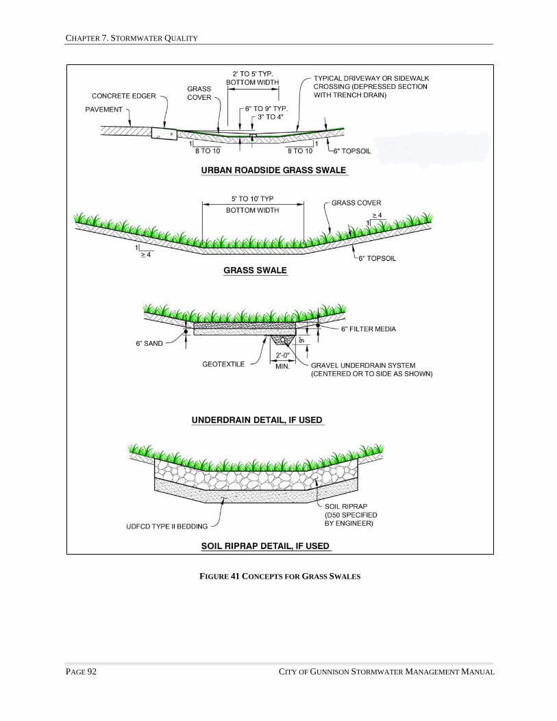
CHAPTER 7. STORMWATER QUALITY
PAGE 92 CITY OF GUNNISON STORMWATER MANAGEMENT MANUAL
FIGURE 41 CONCEPTS FOR GRASS SWALES

CHAPTER 7. STORMWATER QUALITY
CITY OF GUNNISON STORMWATER MANAGEMENT MANUAL PAGE 93
FIGURE 42 CONCEPT FOR CONCRETE EDGER

CHAPTER 7. STORMWATER QUALITY
PAGE 94 CITY OF GUNNISON STORMWATER MANAGEMENT MANUAL
FIGURE 43 CONCEPT FOR OUTLET STRUCTURE WITH PARALLEL WINGWALLS AND FLUSH BAR GRATING (INTEGRAL MICROPOOL SHOWN)

CHAPTER 7. STORMWATER QUALITY
CITY OF GUNNISON STORMWATER MANAGEMENT MANUAL PAGE 95
FIGURE 44 CONCEPT FOR OUTLET STRUCTURE WITH FLARED WINGWALLS AND HANDRAIL (INTEGRAL MICROPOOL SHOWN)

CHAPTER 7. STORMWATER QUALITY
PAGE 96 CITY OF GUNNISON STORMWATER MANAGEMENT MANUAL
FIGURE 45 CONCEPT FOR OUTLET STRUCTURE WITH PARALLEL WINGWALLS AND FLUSH BAR GRATING
(EXTERNAL MICROPOOL SHOWN)
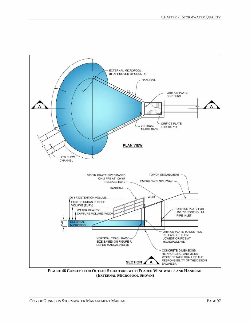
CHAPTER 7. STORMWATER QUALITY
CITY OF GUNNISON STORMWATER MANAGEMENT MANUAL PAGE 97
FIGURE 46 CONCEPT FOR OUTLET STRUCTURE WITH FLARED WINGWALLS AND HANDRAIL (EXTERNAL MICROPOOL SHOWN)

CHAPTER 7. STORMWATER QUALITY
PAGE 98 CITY OF GUNNISON STORMWATER MANAGEMENT MANUAL
FIGURE 47 CONCEPT FOR INTEGRAL FOREBAY AT PIPE OUTFALL

CHAPTER 7. STORMWATER QUALITY
CITY OF GUNNISON STORMWATER MANAGEMENT MANUAL PAGE 99
FIGURE 48 CONCEPT FOR INTEGRAL FOREBAY AT END SECTION

CHAPTER 7. STORMWATER QUALITY
PAGE 100 CITY OF GUNNISON STORMWATER MANAGEMENT MANUAL
FIGURE 49 CONCEPT FOR MODIFIED EXTENDED DETENTION BASIN FOR SMALL SITES (CONCRETE LOW FLOW CHANNEL SHOWN)

CHAPTER 7. STORMWATER QUALITY
CITY OF GUNNISON STORMWATER MANAGEMENT MANUAL PAGE 101
FIGURE 50 CONCEPT FOR MODIFIED EXTENDED DETENTION BASIN FOR SMALL SITES (BENCHED LOW FLOW CHANNEL SHOWN)

CHAPTER 7. STORMWATER QUALITY
PAGE 102 CITY OF GUNNISON STORMWATER MANAGEMENT MANUAL
FIGURE 51 CONCEPT FOR POROUS LANDSCAPE DETENTION IN PARKING LOT
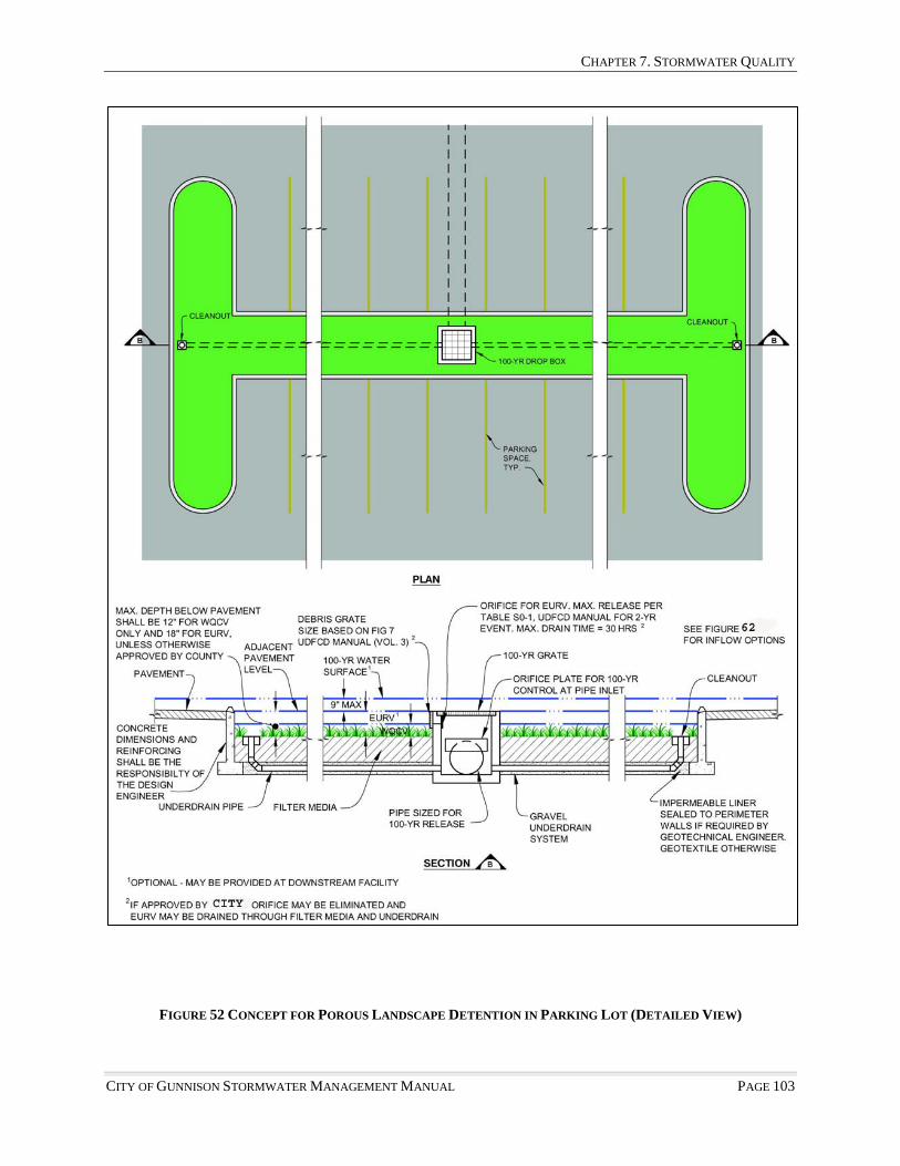
CHAPTER 7. STORMWATER QUALITY
CITY OF GUNNISON STORMWATER MANAGEMENT MANUAL PAGE 103
FIGURE 52 CONCEPT FOR POROUS LANDSCAPE DETENTION IN PARKING LOT (DETAILED VIEW)

CHAPTER 7. STORMWATER QUALITY
PAGE 104 CITY OF GUNNISON STORMWATER MANAGEMENT MANUAL
FIGURE 53 CONCEPTS FOR INFLOWS TO POROUS LANDSCAPE DETENTION IN PARKING LOT

CHAPTER 7. STORMWATER QUALITY
CITY OF GUNNISON STORMWATER MANAGEMENT MANUAL PAGE 105
FIGURE 54 CONCEPTS FOR POROUS LANDSCAPE DETENTION IN LANDSCAPING

CHAPTER 7. STORMWATER QUALITY
PAGE 106 CITY OF GUNNISON STORMWATER MANAGEMENT MANUAL
FIGURE 55 CONCEPTS FOR POROUS LANDSCAPE DETENTION STRUCTURES

CHAPTER 8. DRAINAGE REPORT AND CONSTRUCTION DRAWING SUBMITTAL REQUIREMENTS
CITY OF GUNNISON STORMWATER MANAGEMENT MANUAL PAGE 107
Chapter 8 Drainage Report and Construction Drawing Submittal
Requirements §8.0 INTRODUCTION The requirements presented in this section shall be used to aid the design engineer or applicant in the preparation of drainage reports, drainage studies, and construction drawings for stormwater management facilities. The requirements presented are the minimum necessary and will be used to evaluate the adequacy of all submittals to the City. §8.1 REVIEW PROCESS 8.1.1 Relationship to Land Development Review Procedure. The review of the stormwater design is integrated with the review-specific development processes set forth in Section 6 of the LDC, whether the application is for a Land Use Development or Site Development Application. Table 8-1 notes that in several submittal types the City Engineer shall determine submittal requirements. The intent is to ensure that adequate data is provided, but exclude redundancy or information that is not necessary. Submittal determinations will be made no later than seven days after a pre-application conference. The City Engineer will consider the proposed land use, the capability and function of the existing stormwater facilities and the guidelines, principles and minimum standards found in Chapter 2 of this Manual in determining submittal requirements. The City Engineer is authorized to designate a specific Drainage Report Phase (I, II, III), to waive any or all phase requirements, or require additional detail submittal requirements as deemed necessary.
TABLE 8-1 DRAINAGE REPORT SUBMITTAL REQUIREMENTS
Submittal Type Drainage Submittal Requirements Review Body
Map Amendment Determined by the City Engineer P&Z and City Council Planned Development PUD-O or PUD-M
Phase II Drainage Report P&Z and City Council
Site Development Application Determined by City Engineer Staff Conditional Use Determined by City Engineer P&Z Preliminary Subdivision Plat Phase II Drainage Report P&Z Final Subdivision Plat/Replat Phase III Drainage Report P&Z and City Council Minor Subdivision Determined by City Engineer P&Z and City Council Exempt Subdivision Determined by City Engineer Staff Note: The Drainage Report submittal requirements as outlined in this Table are general guidelines and do not represent all circumstances under which specific drainage submittals may be required. Prior to the submittal, the applicant shall consult with the City Engineer for submittal requirements regarding applications or processes not addressed in this Table.
8.1.2 Submittal Adequacy. Any submittal with incomplete or absent information may result in the report being returned to the author without any review. The City reserves the right to require additional information with any submittal. 8.1.3 Duration of Report Validity. Phase III Drainage Reports will be valid for two years from the date of City acceptance. If construction drawings have not been developed and accepted by the City within two years of the Drainage Report acceptance, the Phase III Drainage Report must be submitted for

CHAPTER 8. DRAINAGE REPORT AND CONSTRUCTION DRAWING SUBMITTAL REQUIREMENTS
PAGE 108 CITY OF GUNNISON STORMWATER MANAGEMENT MANUAL
re-acceptance. In order to be re-accepted, it must be demonstrated that the concepts, designs, and calculations presented in the report are consistent with presently adopted standards. Phase I, Phase II, and Master Plan Drainage studies are not formally accepted, and therefore not affected by the acceptance period. 8.1.4 Acceptance. Acceptance of stormwater improvements shall be in accordance with the provisions of Section 4.2.J of the LDC. §8.2 SUMMARY TABLE OF REQUIRED CERTIFICATIONS AND CITY ACTION
Table 8-2 Summary of Required Certifications and City Action ITEM CERTIFICATION REQUIRED CITY ACTON
Phase II Drainage Report Engineer/Developer Review and comment Phase III Drainage Report Engineer/Developer Approval Transitional Phase II Drainage Report Engineer/Developer Approval Construction Drawings Engineer Approval Record Drawings Engineer/Land Surveyor Probationary Acceptance O&M Manual for Stormwater Facilities Owner/Developer/Engineer Review and Acceptance Floodplain Modification Study Owner/Developer/Engineer Approval §8.3 PHASE II DRAINAGE REPORT AND PLAN 8.3.1 Requirement for Phase II Drainage Report and Plan Submittal. Submittal of a Phase II Drainage Report and Plan is required with specific development or land use proposals, as generally outlined in Table 8-1. The purpose of the Phase II Drainage Report is to identify and provide solutions to the problems that may occur onsite and off-site as a result of the development. The report shall include a cover letter presenting the preliminary design for review and shall be certified by a Professional Engineer licensed in Colorado. 8.3.2 Report Contents. The Phase II Drainage Report generally consists of a narrative portion and appendices with supporting calculations and other pertinent information. The narrative shall lead the reader logically through the entire analysis and design process and provide a clear picture of all stormwater management issues. Discussion of methodology, assumptions, input, and a summary of results shall be provided in the narrative for all hydrologic or hydraulic modeling efforts. Peak flow rates, storage volumes, critical water surface elevations, and stormwater management facility sizes shall also be summarized or discussed in the report narrative. Unless waived by the City Engineer, all pertinent AutoCAD and/or GIS data sets will be submitted with the application. The following is an outline of the minimum Phase II Drainage Report requirements: I. COVER SHEET
A. Name of Project B. Address C. Owner D. Developer E. Registered Colorado Engineer – Stamped documents required F. Submittal date and revision dates as applicable
II. GENERAL LOCATION AND DESCRIPTION
A. Site Location 1. Site Vicinity Map

CHAPTER 8. DRAINAGE REPORT AND CONSTRUCTION DRAWING SUBMITTAL REQUIREMENTS
CITY OF GUNNISON STORMWATER MANAGEMENT MANUAL PAGE 109
2. Township, Range, Section, and ¼ Section 3. Existing and proposed streets, roadways, and highways adjacent to and within the proposed
development, or within the area served by the proposed drainage improvements 4. Names of surrounding or adjacent developments, including land use or zoning information
B. Description of Property
1. Area in acres 2. Ground cover, vegetation, site topography and slopes 3. NRCS Soils Classification Map and discussion 4. Major and minor drainageways 5. Floodplains delineated by updated flood hazard area delineation studies and/or existing FIRM
maps 6. Existing irrigation canals or ditches 7. Significant geologic features 8. Proposed land use and site activities and operations 9. Groundwater data and/or investigations 10. Irrigation practices and potential impacts
III. DRAINAGE BASINS AND SUB-BASINS
A. Major Drainage Basins 1. On-site and off-site major drainage basin characteristics and flow patterns and paths 2. Existing and proposed land development within the basins 3. Discussion of all drainageway planning or floodplain delineation studies that affect the major
drainageways, such as flood hazard area delineation studies and outfall system planning studies
4. Discussion of the condition of the channel within or adjacent to the development, including existing condition, need for improvements, and impact on proposed development
5. Discussion of the impacts of the off-site flow patterns and paths, under fully developed conditions
B. Minor Drainage Basins
1. On-site and off-site minor drainage basin characteristics and flow patterns and paths under historic and developed conditions
2. Existing and proposed land uses within the basins 3. Discussion of irrigation facilities that will influence or be impacted by the site drainage 4. Discussion of the impacts of the off-site flow patterns and paths, under fully developed
conditions IV. DRAINAGE DESIGN CRITERIA
A. Regulations 1. City criteria and optional provisions selected, when applicable 2. UDFCD criteria and optional provisions selected, when applicable
B. Drainage Studies, Outfall Systems Plans, Site Constraints
1. Discuss previous drainage studies or master plans for the site or project that influence the stormwater facility designs.
2. Discuss drainage studies for adjacent developments and how those developments affect the stormwater facility designs.
3. Discuss Outfall Systems Plans and how recommendations in those studies affect the design. 4. Discuss impacts to stormwater management facility design, caused by site constraints, such
as streets, utilities, existing structures, etc.
CHAPTER 8. DRAINAGE REPORT AND CONSTRUCTION DRAWING SUBMITTAL REQUIREMENTS
PAGE 110 CITY OF GUNNISON STORMWATER MANAGEMENT MANUAL
C. Hydrology 1. Runoff calculations method(s) 2. Design storm recurrence intervals 3. Design rainfall 4. Detention storage calculation method(s) 5. Detention storage release rate calculation method
D. Hydraulics
1. Methods used to determine conveyance facility capacities 2. Hydraulic grade line calculation method and discussion of loss coefficients 3. Methods used to calculate water surface profiles 4. Detention pond routing
E. Water Quality Enhancement
1. Discuss proposed BMPs 2. Identify design procedures and WQCV 3. Discuss proposed Source Controls for site activities
F. Groundwater Investigation
1. Discuss groundwater investigations and results 2. Identify potential groundwater issues and remediation measures
V. STORMWATER MANAGEMENT FACILITY DESIGN
A. Stormwater Conveyance Facilities 1. Discuss general conveyance concepts 2. Discuss proposed drainage paths and patterns 3. Discuss storm sewer design, including inlet and pipe locations and sizes, tributary basins and
areas, peak flow rates at design points, hydraulic grade lines, etc. 4. Discuss storm sewer outfall locations and design, including method of energy dissipation 5. Discuss how runoff is conveyed from all outfalls to the nearest major drainageway, including
a discussion of the flow path and capacity downstream of the outfall to the nearest major drainageway
6. Discuss open channel and swale designs, including dimensions, alignments, tributary basins and areas, peak flow rates at design points, stabilization and grade control improvements, low flow or trickle channel capacities, water surface elevations, etc.
7. Discuss allowable street capacities 8. Discuss maintenance aspects of the design and easements and tracts that are required for
stormwater conveyance purposes 9. Discussion of the facilities needed off-site for the conveyance of minor and major flows to
the major drainageway
B. Stormwater Storage Facilities 1. Discuss detention pond designs, including release rates, storage volumes and water surface
elevations for the 2-year, 100-year, and emergency overflow conditions, outlet structure design, emergency spillway design, etc.
2. Discuss pond outfall locations and design, including method of energy dissipation 3. Discuss how runoff is conveyed from all pond outfalls to the nearest major drainageway,
including discussion of the flow path and capacity downstream of the outfall to the nearest major drainageway
4. Discuss maintenance aspects of the design and easements and tracts that are required for stormwater storage purposes

CHAPTER 8. DRAINAGE REPORT AND CONSTRUCTION DRAWING SUBMITTAL REQUIREMENTS
CITY OF GUNNISON STORMWATER MANAGEMENT MANUAL PAGE 111
C. Water Quality Enhancement Best Management Practices 1. Discuss the design of all structural water quality BMPs, including tributary areas, sizing,
treatment volumes, design features, etc. 2. Discuss how runoff is conveyed from all pond outfalls to the nearest major drainageway,
including a discussion of the flow path and capacity downstream of the outfall to the nearest major drainageway
3. Discuss the operation and maintenance aspects of the design and easements and tracts that are required for stormwater quality enhancement purposes
4. Discuss the source controls that are necessary to prevent the potential for illicit discharge from site activities
D. Floodplain
Undesignated Floodplain 1. Discuss resources and methodology for delineation of floodplain
Designated Floodplain 1. Discuss the source of the floodplain information and level of detail (FEMA Flood Insurance
Rate Maps) 2. Discuss details of floodplain modifications, including level of encroachment, velocities,
depths, stabilization measures, water surface elevations, etc. 3. Discuss Floodplain Modification Studies, including Conditional Letter of Map Revision
(CLOMR) and Letter of Map Revision (LOMR) requirements
E. Groundwater 1. Discuss improvements to mitigate groundwater impacts
F. Irrigation System
1. Discuss design functions that avoid discharge into existing and future irrigation systems and define design features separating stormwater from ditch flows.
2. If irrigation ditch systems are proposed to receive outfall a hydrological and hydraulic analysis must demonstrate that the ditch system is capable of functioning in such a capacity.
3. Provide written proof demonstrating that the design engineer has coordinated with the irrigation ditch owner on all design elements that may affect the ditch operation and function.
G. Additional Permitting Requirements
1. Compliance with Section 404 of the Clean Water Act 2. Compliance with the Endangered Species Act 3. Other local, State, or Federal requirements
H. General
1. Discuss all tables, figures, charts, drawings, etc. that were used in design of stormwater management facilities and describe materials that are included in the appendix of the report
VI. CONCLUSIONS
A. Compliance with Standards 1. City of Gunnison Criteria 2. Master Plans and Outfall System Plans
B. Variances
1. Identify provisions by section number for which a variance will be requested, or has been approved by the City (final version of Drainage Report)

CHAPTER 8. DRAINAGE REPORT AND CONSTRUCTION DRAWING SUBMITTAL REQUIREMENTS
PAGE 112 CITY OF GUNNISON STORMWATER MANAGEMENT MANUAL
2. Provide justification for each variance requested
C. Drainage Concept 1. Discuss overall effectiveness of stormwater management design to properly convey, store and
treat stormwater VII. REFERENCES Reference all criteria, master plans, reports, or other technical information used in development of the concepts discussed in the drainage report. VIII. APPENDICES
A. Hydrologic Computations 1. Determination of runoff coefficients and times of concentration 2. Land use assumptions for off-site areas 3. Colorado Urban Hydrograph Procedure input parameter determination 4. SWMM Input parameter determination 5. Peak flow rate calculations for the minor and major storms 6. Rainfall information 7. CUHP/SWMM input and output 8. Hydrograph data, if applicable 9. Connectivity diagram showing relationship/connectivity of basins, conveyance facilities,
detention ponds, and design points 10. Floodplain hydrology
B. Hydraulic Computations
1. Culvert capacities 2. Storm sewer capacities and hydraulic grade lines, including the loss coefficients 3. Street capacities a. Inlet capacities 4. Open channel or swale capacities 5. Low flow and trickle channels 6. Stabilization and grade control improvements 7. Water surface profiles 8. State-storage-discharge determination for detention ponds 9. Detention pond routing calculations 10. Emergency spillway sizing calculations 11. Downstream/outfall capacity to the nearest major drainageway 12. Energy dissipation at pipe outfalls 13. Floodplain modeling
C. Water Quality Enhancement Best Management Practices
1. Design and Sizing
D. Referenced Information 1. Copies of pertinent portions of all referenced materials or drainage reports.
Note: Hydraulic computations will be required with the Phase II Drainage Report if the information necessary to perform the calculations is available. Availability of information will be determined by the City Engineer, based on the level of detail contained in the application submittal. Regardless of present availability, all hydraulic computations will be required in the Phase III drainage report.

CHAPTER 8. DRAINAGE REPORT AND CONSTRUCTION DRAWING SUBMITTAL REQUIREMENTS
CITY OF GUNNISON STORMWATER MANAGEMENT MANUAL PAGE 113
8.3.3 Phase II Drainage Plan Requirements. The following is an outline of the Minimum Phase II Drainage Plan requirements. All plans must be bound. I. OVERALL DRAINAGE PLAN
A. 24" x 36" in size, 22" x 34" also acceptable when half size sets will be produced B. Title block and legend C. Show boundaries of entire development or project D. Existing or proposed streets, roadways, or highways E. Show limits of all major basins, including off-site basins F. General drainage patterns and flow paths, including those entering and leaving the site G. Topographic information with a 5-foot maximum contour interval H. Identify existing and proposed stormwater management facilities, upstream, downstream, or
within the site, which will provide a stormwater management function for the site I. Overlay or figure showing layout of Detailed Drainage Plan sheets
II. DETAILED DRAINAGE PLANS
A. 24" x 36" in size, 22" x 34" also acceptable when half size sets will be produced B. Title block and legend C. Basin designations, design points, flow rates, volumes, release rates, consistent with City
standards D. Scale 1"= 20' to 1"= 100', as required to show sufficient detail E. Existing (dashed or screened) and proposed (solid) contours with a 2 foot maximum contour
intervals. In terrain where the slope exceeds 15%, the maximum interval is 5 feet. Contour must extend a minimum of 100 feet beyond property lines.
F. Existing utilities and structures G. All property lines and easements with type of easement noted H. Adjacent developments or ownerships I. Streets and roadways with ROW and flow line widths, type of curb and gutter or roadside swale,
slopes flow directions, and crosspans J. Drainage basin and sub-basin limits K. Existing and proposed stormwater management facilities, including irrigation ditches, roadside
swales, open channels and drainageways, storm sewers, culverts, detention ponds, water quality enhancement structures or features, etc. Information must be included regarding materials, sizes, shapes, and slopes
L. Proposed outfall points and existing or proposed facilities to convey runoff to the nearest major drainageway, without damage to downstream properties
M. Location and elevation of all existing and proposed 100-year floodplain boundaries, including the source of designation. All floodplain designations that exist for the site should be included, i.e. FEMA, FIS, FHAD, and others.
N. Summary Runoff Table NOTE: The items listed above will be required with the Phase II Drainage Report, or a written explanation as to why information cannot be provided.
CHAPTER 8. DRAINAGE REPORT AND CONSTRUCTION DRAWING SUBMITTAL REQUIREMENTS
PAGE 114 CITY OF GUNNISON STORMWATER MANAGEMENT MANUAL
§8.4 PHASE III DRAINAGE REPORT AND PLAN 8.4.1 Requirement for Phase III Drainage Report and Plan Submittal. The purpose of the Phase III Drainage Report is to update the concepts, and to present the design details on construction plans for the drainage facilities discussed in the Phase II Drainage Report. Also, any change to the Phase II concept must be presented. All reports shall be typed on 8 1/2" x 11" paper and bound. The drawings, figures, charts and/or tables shall be bound with the report or included in a folder/pocket attached to the back of the report. 8.4.2 Report Contents. The Phase III Drainage Report shall be prepared in accordance with the outline shown 8.3.2 above. 8.4.3 Certification Statement. The report shall be prepared by or under the direction of an engineer licensed in Colorado, certified as shown below. The report shall contain a developer certification sheet as follows:
“I hereby affirm that this report and the plan for the Phase III drainage design of (Name of Development) was prepared by me, or under my direct supervision for the owners thereof, in accordance with the provisions of the City of Gunnison Stormwater Management Manual and the Urban Drainage and Flood Control District Criteria Manual, and approved and variances and exceptions thereto. I understand that the City of Gunnison does not and will not assume liability for drainage facilities designed by others.”
SIGNATURE: Registered Professional Engineer State of Colorado No. (Affix Seal)
“(Name of Developer) hereby certifies that the drainage facilities for (Name of Development) shall be constructed according to the design presented in this report. I understand that the City of Gunnison does not and will not assume liability for the drainage facilities designed and/or certified by my engineer and that the City of Gunnison reviews drainage plans pursuant to Colorado Revised Statutes Title 30, Article 28; but cannot, on behalf of (Name of Development), guarantee that final drainage design review will absolve (Name of Developer) and/or their successors and/or assigns of future liability for improper design. I further understand that approval of the Final Plan, Final Development Plan, and/or Subdivision Development Plan does not imply approval of my engineer’s drainage design.”
Name of Developer Authorized Signature
8.4.4 Electronic Submittal Requirements. A complete, electronic copy of the approved version of the Phase III Drainage Report, including all drawings, plates, figures, and tables must be submitted on compact disc before execution of the plat or plans by the Planning and Zoning Commission. §8.5 SPECIAL DRAINAGE REPORTS 8.5.1 Transitional Phase II Drainage Report. The Phase II Drainage Report requirements may be reduced at the request of the applicant if there is uncertainty regarding the final developed characteristics of individual parcels, lots, or sites within the proposed development. There is frequently uncertainty with

CHAPTER 8. DRAINAGE REPORT AND CONSTRUCTION DRAWING SUBMITTAL REQUIREMENTS
CITY OF GUNNISON STORMWATER MANAGEMENT MANUAL PAGE 115
commercial and business park developments at the preliminary or final plat stage regarding the size and placement of buildings, the detailed lot or parcel grading, the extent of paved areas, and the location of local stormwater management facilities and on-site detention facilities, if regional detention is not provided for the entire development. As the individual lots or parcels develop, separate Phase III Drainage Reports are typically prepared as the site characteristics and layout are determined. §8.6 STORMWATER FACILITIES MAINTENANCE AGREEMENT Stormwater Management Facilities must be properly maintained in order to ensure that they function as designed. The City requires that a Stormwater Facilities Maintenance Agreement be executed for all stormwater facilities. The agreement requires that the stormwater management facilities be maintained in accordance with the Operation and Maintenance Manual for the facility. The City may elect to accept the dedication and maintenance of regional scale facilities, but only if a dedicated revenue is established to operate and maintain such facilities. The City shall not accept maintenance of smaller stormwater facilities developed on private property. §8.7 FACILITIES OPERATION AND MAINTENANCE 8.7.1 Operation and Maintenance Manual Requirement. An Operations and Maintenance (O&M)Manual must be developed in conjunction with the final design to provide operation and maintenance guidance for all detention ponds, open channels, post-construction best management practices, and other stormwater management facilities as determined by the City. The Operations and Maintenance Manual must be submitted and accepted by the City prior to City acceptance of the construction drawings. The O&M Manual shall be prepared by the design engineer and certified by the owner and design engineer in accordance with Chapter 9 of this manual. §8.8 CONSTRUCTION DRAWINGS 8.8.1 Stormwater Management Improvements. Stormwater management improvements within the public rights-of-way, in drainage easements, or developed on private property are required to be designed, constructed and accepted in accordance with City standards and criteria. City acceptance of final construction plans is a condition of issuance of development and building permits. 8.8.2 Construction Plan Submittal. Construction-level drawings shall be submitted with the Phase III Drainage Report. 1. Construction Plan Requirements. The construction drawings shall comply with the requirements specified in the City of Gunnison Construction Standards and these Criteria. The construction drawings shall be prepared in accordance with sound engineering principles, City Criteria, and the City requirements for subdivision design. Construction plan design shall include the following information, at a minimum, for the specific facilities or components of the stormwater management system.
I. STORM SEWER AND CULVERTS A. Plan view showing horizontal locations of all pipes, inlets, manholes, junction boxes, and
outlet structures with appropriate horizontal control B. All streets, roadways, highways, property lines, ROW lines, existing and proposed easements
and tracts C. Profile of all pipe mains, laterals, or culverts with all inverts, rim elevations, sizes, lengths,
slopes, design flow rates
CHAPTER 8. DRAINAGE REPORT AND CONSTRUCTION DRAWING SUBMITTAL REQUIREMENTS
PAGE 116 CITY OF GUNNISON STORMWATER MANAGEMENT MANUAL
D. Minor and major storm hydraulic grade lines E. Pipe outlet protection on plan and profile views F. Utilities, adjacent to or crossing storm sewer or culver alignment G. 1"= 20' scale, minimum, grading details for all pipe and culvert inlets and outlets H. Maintenance access improvements I. City of Gunnison Standard Details J. Additional design details, as required K. City of Gunnison Standard Notes
II. OPEN CHANNELS, SWALES, CHANNEL STABILIZATION
A. Plan view showing horizontal locations of all channels and swales, including locations of grade control structures and stabilization measures, such as check structures, drop structures and stabilization measures, such as check structures, drop structures, toe protection, bank stabilization, low flow or trickle channels, with appropriate horizontal control
B. All streets, roadways, highways, property lines, ROW lines, existing and proposed easements and tracts
C. Profile along channel alignment with all invert elevation and top of channel bank elevations, and design flow rates
D. Water surface limits on plan view E. Water surface profiles for the minor storm , major storm, and emergency conditions F. Maintenance access improvements G. Side tributary channels and pipe outlets H. Utilities adjacent to or crossing channel alignment I. City of Gunnison Standard Details J. Additional design details, as required K. City of Gunnison Standard Notes
III. DETENTION/STORAGE FACILITIES
A. Plan view showing horizontal locations of the pond, including locations of low flow or trickle channels, outlet structures, emergency overflow spillway, pipe or channel inlets, etc. with appropriate horizontal control
B. All streets, roadways, highways, property lines, ROW lines, existing and proposed easements and tracts
C. Profile along trickle or low flow channel from all inlets/structures to the outlet structure and pipe with all invert and outlet structure elevations and water surface elevations
D. 1"= 20' scale, minimum, grading details for all pipe and culvert inlets and outlets E. Water surface limits for the minor storm, major storm, and emergency overflow conditions F. Summary table on plan view with stage-storage-discharge characteristics G. Maintenance access improvements H. Utilities adjacent to or crossing the detention area I. City of Gunnison Standard Details J. Additional design details, as required K. City of Gunnison Standard Notes
IV. WATER QUALITY ENHANCEMENT BMPs
A. Plan view showing horizontal locations of the improvements B. All streets, roadways, highways, property lines, ROW lines, existing and proposed easements
and tracts C. Profile of improvements, as required D. Maintenance access improvements E. Utilities adjacent to or crossing the improvements

CHAPTER 8. DRAINAGE REPORT AND CONSTRUCTION DRAWING SUBMITTAL REQUIREMENTS
CITY OF GUNNISON STORMWATER MANAGEMENT MANUAL PAGE 117
F. City of Gunnison Standard Details G. Additional design details, as required H. City of Gunnison Standard Notes
8.8.3 Certification. Construction Drawings submitted for review and acceptance shall be prepared by a professional engineer, registered in the State of Colorado. The construction drawings must include the following statement on the cover sheet: “I hereby affirm that these construction drawings for (name of subdivision, development, or project) were prepared by me (or under my direct supervision) in accordance with the requirements of the Construction Standards and the City of Gunnison Stormwater Management Manual.”
Name of Engineer PE Number Name of Engineering Firm
This statement shall be signed, stamped and dated by the Registered Professional Engineer who prepared or directed the preparation of the drawings. 8.8.4 Record Drawing Requirements. Record drawings, including the required “Statements of Substantial Completion” by the Project Engineer and Surveyor shall be submitted in accordance with the City of Gunnison Stormwater Management Manual. The record drawings shall be submitted as original black line reproductions suitable for scanning as a computer image in a format acceptable to the Department of Public Works, or in the case of being a formal development application the plan will be submitted to the Community Development Department. In order to efficiently update the City’s system-wide stormwater inventory maps, the City requires that electronic files (in AutoCad 12 or newer format, or as allowed by the Public Works Director) be provided in addition to hard copy record drawings.

CHAPTER 9. CONSTRUCTION STORMWATER MANAGEMENT BEST MANAGEMENT PRACTICES
PAGE 118 CITY OF GUNNISON STORMWATER MANAGEMENT MANUAL
Chapter 9 Construction Stormwater Management Best Management Practices §9.0 INTRODUCTION Effective management of stormwater runoff during construction activities is critical to the protection of water resources. The Federal Clean Water Act and the Colorado Water Quality Control Act require stormwater discharge permits during construction at development and redevelopment sites that disturb one or more acres of land. Both erosion and sediment controls are necessary for effective site management as well as effective material management and site management practices (Figure 56). This chapter provides an overview of erosion and sediment control principles and information on construction best management practices (BMPs). BMP Fact Sheets are provided, containing information on applicability, installation, maintenance, and design details with notes. The Fact Sheets are stand-alone documents that can be inserted directly into a City of Gunnison Stormwater Management Plan. Information is also provided on construction in or adjacent to waterways, construction dewatering, and linear construction projects, such as roadways and utilities.
FIGURE 56 COMPONENTS OF EFFECTIVE STORMWATER MANAGEMENT AT CONSTRUCTION SITES

CHAPTER 9. CONSTRUCTION STORMWATER MANAGEMENT BEST MANAGEMENT PRACTICES
CITY OF GUNNISON STORMWATER MANAGEMENT MANUAL PAGE 119
§9.1 FUNDAMENTAL EROSION AND SEDIMENT CONTROL PRINCIPLES 9.1.1 Erosion. Water erosion has five primary mechanisms: raindrop erosion, sheet erosion, rill erosion, gully erosion and channel erosion. Raindrops dislodge soil particles, making them more susceptible to movement by overland water flow. As the flow changes from a shallow sheet to a deeper rill flow, the flow velocity and shear stresses increase, which detach and transport soil particles. This action begins to cut into the soil mantle and form small channels. Rills are small, well-defined channels that are only a few inches deep. Gullies occur as the flows in rills come together into larger channels. Rills caused by erosion can be smoothed out by standard surface treatments such as harrowing. Gully erosion, however, typically requires heavy equipment to regrade and stabilize the land surface. Wind erosion occurs when winds of sufficient velocity create movement of soil particles. The potential for wind erosion is dependent upon soil cover, soil particle size, wind velocity, duration of wind and unsheltered distance. Erodibility of soils is affected by multiple factors including physical soil characteristics, slope steepness, slope lengths, vegetative cover, and rainfall characteristics. Physical properties of soils such as particle size, cohesiveness, and density affect erodibility. 9.1.2 Effective Erosion and Sediment Control. It is better to minimize erosion than to rely solely on sedimentation removal from construction site runoff. Erosion control BMPs limit the amount and rate of erosion occurring on disturbed areas. Sediment control BMPs attempt to capture the soil that has been eroded before it leaves the construction site. Despite the use of both erosion control and sediment control BMPs, some amount of sediment will remain in runoff leaving a construction site, but the use of a “treatment train” of practices can help to minimize offsite transport of sediment. The last line of treatment such as inlet protection and sediment basins should be viewed as “polishing” BMPs, as opposed to the only treatment on the site. BMPs should be combined and selected to meet these objectives: • Conduct land-disturbing activities in a manner that effectively reduces accelerated soil erosion and
reduces sediment movement and deposition off-site. • Schedule construction activities to minimize the total amount of soil exposed at any given time. • Establish temporary or permanent cover on areas that have been disturbed as soon as practical after
grading is completed. • Design and construct temporary or permanent facilities to limit the flow of water to non-erosive velocities
for the conveyance of water around, though, or from the disturbed area. • Remove sediment caused by accelerated soil erosion from surface runoff water before it leaves the site. • Stabilize disturbed areas with permanent vegetative cover and provide permanent stormwater quality
control measures for the post-construction condition.
FIGURE 57 EROSION

CHAPTER 9. CONSTRUCTION STORMWATER MANAGEMENT BEST MANAGEMENT PRACTICES
PAGE 120 CITY OF GUNNISON STORMWATER MANAGEMENT MANUAL
State Construction Phase Permitting
Stormwater runoff controls from construction sites are mandated by the Federal Water Pollution Control Act (Clean Water Act). In Colorado, the EPA has delegated authority to the Colorado Department of Public Health and Environment (CDPHE). CDPHE, specifically the Water Quality Control Division, issues stormwater and wastewater discharge permits under the Colorado Discharge Permit System (CDPS) Regulation promulgated by the Water Quality Control Commission.
§9.2 COLORADO CONSTRUCTION STORMWATER DISCHARGE PERMITS Within the City of Gunnison boundary, development or redevelopment projects with one or more acres of potential disturbance are required to obtain both city and state permits related to construction-phase stormwater discharges. The area of disturbance includes construction activities that are part of a larger common plan of development or sale and may include “separate” areas where construction practices will occur at different times. Areas used for staging, materials storage, temporary construction site access, off-site borrow areas and other construction related activities should also be included when determining the project area and area of disturbance permitted. In some cases, a construction discharge permit will be required by the City, but not the state. A City permit is required for all projects requiring a state permit as well as construction in the proximity of a floodplain and/or receiving water, steep slopes, and/or areas of known contamination, or on other sites greater than one acre. The CDPS General Permit requires the owner and/or operator (frequently the contractor) to develop a SWMP. Although CDPHE does not require that the SWMP be submitted for approval, the City requires submittal of a SWMP (or comparable document) which must be approved prior to issuance of construction-related permits (e.g., grading permit, land disturbance permit). Because SWMPs are “living documents” that must be updated and maintained as the phases of construction progress, ideally, one master document must be developed that is inclusive of both the state and local requirements, as opposed to maintaining duplicate records. Always obtain the state permit application and guidance directly from the state agency to ensure that all currently applicable requirements are met. In Colorado, this information can be obtained from the CDPHE CDPS General Permit for Stormwater Discharges Associated with Construction Activities. §9.3 2009 FEDERAL EFFLUENT LIMITATION GUIDELINES On December 1, 2009, the EPA published Effluent Limitation Guidelines in the Federal Register (Volume 74, Number 229, pages 62997-63057) establishing technology-based effluent limitation guidelines (ELGs) and new source performance standards (NSPS) for the construction and development industry. This rule requires construction site owners and operators to implement a range of erosion and sediment control measures and pollution prevention practices to control pollutants in discharges from construction sites. Additionally, the rule requires monitoring and sampling of stormwater discharges and compliance with a numeric standard for turbidity in these discharges for larger construction sites (i.e., 10 acres or more). The rule, including numeric effluent limits, was legally challenged in 2010 and, as of October 2010, the EPA was in the process of reconsidering the numeric effluents limit from the rule. Other portions of the rule will remain in effect while the EPA reevaluates the numeric limits. In Colorado, unless constructing a federal project or working on an Indian reservation, construction stormwater discharge permits are issued by CDPHE under the CDPS General Permit for Stormwater Discharges Associated with Construction Activity (CDPS Permit No. COD-030000). This permit was first issued in 1997, and is effective through June 30, 2012. It is anticipated that CDPHE will issue a new general permit in 2012 that will reflect the guidelines, with the possible exception of the numeric limits which may still be under reevaluation at the time that CDPHE issues the new permit. Existing state stormwater requirements will remain in effect until a new general permit is issued.

CHAPTER 9. CONSTRUCTION STORMWATER MANAGEMENT BEST MANAGEMENT PRACTICES
CITY OF GUNNISON STORMWATER MANAGEMENT MANUAL PAGE 121
§9.4 PREPARING AND IMPLEMENTING A STORMWATER MANAGEMENT PLAN (SWMP) A SWMP is developed prior to construction and kept current for the duration of construction. This section includes recommendations for SWMP preparation and BMP inspection, maintenance and removal. 9.4.1 General SWMP Recommendations
A. At a minimum, a SWMP communicates and satisfies the following:
1. identifies all potential sources of pollution which may affect the quality of stormwater discharges associated with construction activity;
2. describes the practices to be used to reduce the pollutants in stormwater discharges associated
with construction activity including the installation, implementation and maintenance requirements; and,
3. be prepared in accordance with good engineering practices and be updated throughout
construction and stabilization of the site. B. Implement the provisions of the SWMP as written an updated, from commencement of construction activity until final stabilization is complete. The SWMP typically requires additions or other modifications once construction commences, and documentation of all modifications and amendments is typically required by the construction stormwater permit. Records of all inspections, BMP maintenance, and communications with the owner and/or engineer should be kept on-site, with the SWMP. These records should be recognized as part of the SWMP but changes to the practices identified in the SWMP should not be made without the approval of an engineer. C. The SWMP should include additional discussion or plans for any special requirements of the site. Special requirements include Spill Prevention Control and Countermeasure (SPCC) plans under Section 311 of the Clean Water Act, or BMP programs otherwise required by another CDPS permit.
9.4.2 SWMP Elements
The City SWMP includes the following as a minimum. When some sections are not applicable, include a statement to that effect.
A. Site Description. Clearly describe the construction activity, including:
• the nature of the construction activity at the site; • the proposed sequence for major activities; • estimates of the total area of the site, and the area and location expected to be disturbed by
clearing, excavation, grading, or other construction activities; • a summary of any existing data used in the development of the site construction plans or SWMP
that describe the soil or existing potential for soil erosion; • a description of the existing vegetation at the site and an estimate of the percent vegetative ground
cover; • the location and description of all potential pollution sources, including ground surface disturbing
activities (see CDPHE Stormwater General Permit for description), vehicle fueling, storage of fertilizers or chemicals, etc.;

CHAPTER 9. CONSTRUCTION STORMWATER MANAGEMENT BEST MANAGEMENT PRACTICES
PAGE 122 CITY OF GUNNISON STORMWATER MANAGEMENT MANUAL
• the location and description of any anticipated allowable sources of non-stormwater discharge at the site, e.g., uncontaminated springs, landscape irrigation return flow, construction dewatering, and concrete washout; and,
• the name of the receiving water(s) and the size, type and location of any outfall(s). If the stormwater discharge is to the municipal storm sewer system, describe the location of the storm sewer discharge, and the ultimate receiving water(s).
B. Site Map. Include a legible site map(s), showing the entire site, identifying:
• construction site boundaries; • all areas of ground surface disturbance; areas of cut and fill; • areas used for storage of building materials, equipment, soil, or waste; • locations of dedicated asphalt or concrete batch plants; • locations of all structural BMPs; • locations of non-structural BMPs as applicable; and • locations of springs, streams, wetlands and other surface waters.
C. Stormwater Management Controls. Include a description of all stormwater management controls that will be implemented as part of the construction activity to control pollutants in stormwater discharges. The appropriateness and priorities of stormwater management controls in the SWMP should reflect the potential pollutant sources identified at the facility. The description of stormwater management controls should address the following components, at a minimum:
• SWMP Administration. Identify a specific individual, position, or title that is responsible for
developing, implementing, maintaining, and revising the SWMP. • Identification of Potential Pollutant Sources. Identify and describe sources that may contribute
pollutants to runoff, and provide means of control through BMP selection and implementation. At a minimum, evaluate each of the following potential sources of pollution:
1. all disturbed and stored soils; 2. vehicle tracking of sediments; 3. management of contaminated soils; 4. loading and unloading operations; 5. outdoor storage activities (building materials, fertilizers, chemicals, etc.); 6. vehicle and equipment maintenance and fueling; 7. significant dust or particulate generating processes; 8. routine maintenance activities involving fertilizers, pesticides, detergents, fuels, solvents, oils,
etc.; 9. on-site waste management practices (waste piles, liquid wastes, dumpsters, etc.); 10. concrete truck/equipment washing, including the concrete truck chute and associated fixtures
and equipment; 11. dedicated asphalt and concrete batch plants; 12. non-industrial waste sources such as worker trash and portable toilets; and, 13. other areas or procedures where potential spills can occur.
D. BMPs for Construction Stormwater Pollution Prevention. Identify and describe appropriate BMPs including those listed in this section. Provide enough detail for each BMP to ensure proper implementation, operation, and maintenance.

CHAPTER 9. CONSTRUCTION STORMWATER MANAGEMENT BEST MANAGEMENT PRACTICES
CITY OF GUNNISON STORMWATER MANAGEMENT MANUAL PAGE 123
• Structural Practices for Erosion and Sediment Control (e.g., wattles/sediment control logs and temporary or permanent sediment basins).
• Non-Structural Practices for Erosion and Sediment Control (e.g. temporary vegetation and permanent vegetation).
• Phased BMP Implementation. Describe the relationship between the phases of construction, and the implementation and maintenance of both structural and non-structural stormwater management controls. Project phases might include different operations such as clearing and grubbing; road construction; utility and infrastructure installation; vertical construction; final grading; and final stabilization.
• Materials Handling and Spill Prevention. Materials of interest could include: exposed storage of building materials; paints and solvents; fertilizers or chemicals; waste material; and equipment maintenance or fueling procedures.
• Dedicated Concrete or Asphalt Batch Plants. • Vehicle Tracking Control. This BMP includes minimizing (as practicable) the number of areas
where construction vehicles are required to move from unpaved to paved areas as well as providing structural BMPs at each location.
• Waste Management and Disposal, Including Concrete Washout. • Groundwater and Stormwater Dewatering. These activities often require a separate permit that
includes sampling of processed waters. However, in some cases, these activities can be conducted without a separate permit when processed water is not discharged from the site as surface runoff or discharged into surface waters. The SWMP should describe how these waters will be used (i.e., land application, infiltration, evaporation) and how the specific practices at the site will ensure that these waters are not discharged via runoff.
E. Final Stabilization and Long-Term Stormwater Management
• The SWMP describes the practices used to achieve final stabilization of all disturbed areas at the
site and nay planned practices to control pollutants in stormwater discharges that will occur after construction operations have been completed at the site.
• Final stabilization practices for obtaining a vegetative cover should include, as appropriate: seed mix selection and application methods; soil preparation and amendments; soil stabilization practices (e.g., crimped straw, hydro mulch or rolled erosion control products); and appropriate sediment control BMPs as needed until final stabilization is achieved.
• Final stabilization is reached when all ground surface disturbing activities at the site have been completed, and uniform vegetative cover has been established with an individual plant density of at least 70 percent of pre-disturbance levels, or equivalent permanent, physical erosion reduction methods have been employed.
F. Inspection and Maintenance. The SWMP describes the inspection and maintenance procedures implemented at the site to maintain all erosion and sediment control practices and other protective practices identified in the SWMP in good and effective operating condition. §9.5 INSPECTIONS Routine and post-storm inspections of BMPs are essential to identify maintenance necessary for the BMPs to remain in effective operating conditions. The frequency of inspections is typically influenced by multiple factors including the weather, the phase of construction, activities on site, and the types of BMPs. Checklists and other forms of documentation are also important to meet the requirements of a construction stormwater permit. 9.5.1 Inspection Frequency. The CDPS General Permit requires documented inspections on a biweekly

CHAPTER 9. CONSTRUCTION STORMWATER MANAGEMENT BEST MANAGEMENT PRACTICES
PAGE 124 CITY OF GUNNISON STORMWATER MANAGEMENT MANUAL
Consider using a free internet application that provides real-time weather alerts to keep aware of inclement weather and plan ahead for staff to inspect and maintain BMPs.
basis and within 24 hours of a storm event, with some limited, temporary exceptions for inactive sites. The City recommends daily spot-checks. This is typically reasonable to achieve and can help to ensure that the BMPs remain in good working condition. When snow cover exists over the entire site for an extended period, inspections are not always feasible. This condition should be documented, including date of snowfall and date of melting conditions to bring awareness of and preparation for areas where melting conditions may pose a risk of surface erosion. 9.5.2 Inspection Records. Standard checklists will be developed and used for various types of construction projects (e.g., channel work, large-scale phased construction projects, or small urban sites). The checklist will include the date and name/title of personnel making the inspection. It will note BMP failures, observed deviations from the SWMP, necessary repairs or corrective measures, corrective actions taken, and general observations.
§9.6 MAINTENANCE Types and frequencies of maintenance are BMP-specific. Identify needed maintenance activities during site inspections or during general observations of site conditions. Where BMPs have failed, repairs or changes must be initiated as soon as practical, to minimize the discharge of pollutants. §9.7 DISPOSITION OF TEMPORARY MEASURES Most temporary erosion and sediment control BMPs must be removed within 30 days after final site stabilization is achieved. Some biodegradable BMPs, such as erosion control blankets, are designed to remain in place and would create new areas of disturbance if removed. Trapped sediment and disturbed soil areas resulting from the disposal of temporary measures must be returned to final plan grades and permanently stabilized to prevent further soil erosion. Whenever post-construction BMPs are used for sediment controls during construction, the SWMP will include the steps and actions needed to refurbish these facilities to a fully operational form as post-construction BMPs. The final site work will not be accepted by the city until these BMPs are in final and acceptable form as the original design calls for, which includes lines and grades, volumes, outlet structures, trash racks, landscaping and other measures specified in the site development plans prepared by the design engineer. §9.8 CONSTRUCTION BMPS Design, construction, placement and maintenance details for construction BMPs shall be in conformance with the Urban Stormwater Drainage Manual Additionally, practices include dewatering and construction in waterways, shall be followed for activities within the City boundary. 9.8.1 Construction BMPs Defined in the Urban Drainage Manual. Following is a summary of erosion control, sediment control, material management and site management BMPs.
A. Erosion Control BMPs. Erosion control measures are source controls used to limit erosion of oil. These are typically surface treatments that stabilize soil that has been exposed by excavation or grading, although some limit erosion by redirecting flows or reducing velocities of concentrated flow. Refer to the Urban Stormwater Drainage Manual, Volume 3, Chapter 7 Fact Sheets for the specifics regarding erosion control (EC) practices.
CHAPTER 9. CONSTRUCTION STORMWATER MANAGEMENT BEST MANAGEMENT PRACTICES
CITY OF GUNNISON STORMWATER MANAGEMENT MANUAL PAGE 125
B. Sediment Control BMPs Sediment controls are the second line of defense, capturing soil that has been eroded. Sediment controls generally rely on treatment processes that either provides filtration through a permeable media or that slow runoff to allow settling of suspended particles. Refer to the Urban Stormwater Drainage Manual, Fact Sheets for the specifics regarding sediment control (SC) practices. C. Site Management. Site management is often ultimately the deciding factor in how effective BMPs are at a particular site. BMPs implemented at the site must not only be properly selected and installed, but also must be inspected, maintained and properly repaired for the duration of the construction project. In addition to general site management, there are a number of specific site management practices that affect construction site management. There are several miscellaneous activities that must be carefully conducted to protect water quality such as dewatering operations, temporary batch plants, temporary stream crossings and other practices. As part of the construction kick-off meeting for the project (or for major phases of construction), an effective strategy is to include a training component related to construction site stormwater management. Such training should provide basic education to site personnel regarding the requirements of the state and local construction stormwater permits. D. Material Management. Materials management BMPs are source control practices intended to limit contact of runoff with pollutants commonly found at construction sites such as construction materials and equipment-related fluids. By intentionally controlling and managing areas where chemicals are handled, the likelihood of these materials being transported to waterways is reduced. Refer to the Urban Stormwater Drainage Manual, for the specifics regarding material management (MM) practices.

CHAPTER 9. CONSTRUCTION STORMWATER MANAGEMENT BEST MANAGEMENT PRACTICES
PAGE 126 CITY OF GUNNISON STORMWATER MANAGEMENT MANUAL
TABLE 9-1 OVERVIEW OF CONSTRUCTION BMPS USDM BMP
Reference Functions Erosion Control Sediment Control Site/Material
Management
EROSION CONTROL BMPS EC-1 Surface Roughening Yes No No EC-2 Temporary/Permanent Seeding Yes No No EC-3 Soil Binders Yes No Moderate EC-4 Mulching Yes Moderate No EC-5 Compost Blankets and Filter Berms Yes Moderate No EC-6 Rolled Erosion Control Products Yes No No EC-7 Temporary Slope Drains Yes No No EC-8 Temporary Outlet Protection Yes Moderate No EC-9 Rough Cut Street Control Yes Moderate No EC-10 Earth Dikes / Drainage Swales Yes Moderate No EC-11 Terracing Yes Moderate No EC-12 Check Dams Yes Moderate No EC-13 Streambank Stabilization Yes No No EC-14 Wind Erosion / Dust Control Yes No Moderate
SEDIMENT CONTROL BMPS SC-1 Silt Fence No Yes No SC-2 Sediment Control Log Moderate Yes No SC-3 Straw Bale Barrier No Moderate No SC-4 Bruch Barrier Moderate Moderate No SC-5 Rock Sock (perimeter control) No Yes No SC-6 Inlet Protection (various forms) No Yes No SC-7 Sediment Basins No Yes No SC-8 Sediment Traps No Yes No SC-9 Vegetative Buffers Moderate Yes Yes SC-10 Chemical Treatment Moderate Yes No
MATERIALS MANAGEMENT MM-1 Concrete Washout Area No No Yes MM-2 Stockpile Management Yes Yes Yes MM-3 Good Housekeeping (multiple practices) No No Yes
SITE MANAGEMENT AND OTHER SPECIFIC PRACTICES SM-1 Construction Phasing Moderate Moderate Yes SM-2 Protection of Existing Vegetation Yes Moderate Yes SM-3 Construction Fence No No Yes SM-4 Vehicle Tracking Control Moderate Yes Yes SM-5 Stabilized Construction Roadway Yes Moderate Yes SM-6 Stabilized Staging Area Yes Moderate Yes SM-7 Street Sweeping / Vacuuming No Yes Yes SM-8 Temporary Diversion Channel Yes No No SM-9 Dewatering Operations Moderate Yes Yes SM-10 Temporary Stream Crossing Yes Yes No SM-11 Temporary Batch Plants No No Yes SM-12 Paving and Grinding Operations No No Yes

CHAPTER 9. CONSTRUCTION STORMWATER MANAGEMENT BEST MANAGEMENT PRACTICES
CITY OF GUNNISON STORMWATER MANAGEMENT MANUAL PAGE 127
§9.9 BMP SELECTION AND PLANNING BMPs should be selected based on the physical layout and site conditions that will exist during each stage of construction, because site conditions change through the various stages of construction. In general, three stages of erosion and sediment control plans can be considered. These stages include initial clearing and grading; utility, infrastructure and building construction; and final stabilization. This section focuses on important factors to consider in the development of a SWMP, including site-specific conditions, BMP functions, and other site-related plans. 9.9.1 Site Assessment. Early awareness of site-specific factors that make a site particularly prone to erosion problems can prevent serious problems later during the construction process. A site assessment should include attention to these factors, prior to selection of BMPs:
A. Slopes/Topography and Topographic Changes Due to Grading. Slope length and steepness are two key factors in identifying the types and placement of both erosion and sediment control BMPs. B. Tributary Area/Catchment Size. The overall size of sub-catchment areas are key to determining the types, sizes, spacing and other design requirements for sediment controls appropriate for each drainage area. C. Soils. Regardless of soil type, all disturbed soils require erosion controls; however, NRCS soil maps and geotechnical reports for the development can be used to identify soil conditions where erosion may be particularly difficult to control. D. Vegetation. Onsite vegetation that is to be left undisturbed must be clearly identified in the SWMP and/or the construction plans. Construction fence should be installed to avoid disturbance and compaction of these areas. Maintaining a vegetative buffer, in combination with other perimeter control BMPs, can be effective for minimizing transport of sediment off-site. E. Drainage Infrastructure. Understanding the hydrology of a site is important in the design of sediment controls. Offsite run-on as well as drainage patterns within the site should be thoroughly assessed. The configuration of hill slope areas and waterways, in the context of planned roads and buildings, will determine which erosion and sediment controls will be needed at each phase of construction. F. Sensitive Site Conditions. In cases where construction is occurring in areas of sensitive aquatic habitat, upstream of drinking water supplies, or near areas where threatened and endangered species are a concern, additional layers of protection may be required. These may include redundant BMPs or restrictions on times that construction activities are allowed.
9.9.2 Slope-Length and Runoff Considerations. Cut-and-fill slopes should be designed and constructed to minimize erosion. This requires consideration of the length and steepness of the slope, the soil type, upslope drainage area, groundwater conditions and other applicable factors. The following guidelines should
FIGURE 58 RILLING

CHAPTER 9. CONSTRUCTION STORMWATER MANAGEMENT BEST MANAGEMENT PRACTICES
PAGE 128 CITY OF GUNNISON STORMWATER MANAGEMENT MANUAL
assist site planners and plan reviewers in developing an adequate design: • Rough soil surfaces enhance infiltration and/or lengthen the travel path or runoff, reducing runoff
velocity. See the Surfacing Roughening BMP Fact Sheet. • Temporary diversion dikes should be constructed at the top of long or steep slopes. Diversion dikes or
terraces reduce slope length within the disturbed area. See the Earth Dikes and Drainage Swales BMP Fact Sheet.
• Temporary diversion dikes should be provided whenever:
EQUATION 9-1 RECOMMENDED TEMPORARY DIVERSION DIKE FOR UNDISTURBED TRIBUTARY AREAS
S2L > 2.5
EQUATION 9-2 RECOMMENDED TEMPORARY DIVERSION DIKE FOR DISTURBED TRIBUTARY AREAS
S2L > 1.0
EQUATION 9-3 RECOMMENDED TEMPORARY DIVERSION DIKE FOR PAVED TRIBUTARY AREAS
S2L > 0.25 Where:
S = slope of upstream tributary area (feet/foot) L = length of the upstream slope (feet)
• Concentrated stormwater (e.g., pipe outflow, channel, swale) should not be allowed to flow down cut
or fill slopes unless contained within an adequately-sized temporary channel diversion, a permanent channel, or temporary slope drain.
• Wherever a slope face crosses a water seepage plane that endangers the stability of the slope,
adequate drainage should be provided. • Provide sediment basins or barriers (silt fence) at or near the toe of slopes to trap sediment or to
reduce slope lengths. When flows are concentrated and conveyed down a slope using a slope drain or channel, energy dissipation measures will be required at the conveyance outlet at the toe of the slope.
9.9.3 Using the Revised Universal Soil Loss Equation. The Revised Universal Soil Loss Equation (RUSLE) is an erosion prediction method that has evolved over time, resulting from data collection and analysis efforts extending from the 1930’s through the 1970’s, ultimately published in Agriculture Handbook 282 (Wischmeier and Smith, 1965), then Agriculture Handbook 587 (Wischmeier and Smith, 1978) and Agriculture Handbook 703 (Renard et al., 1997). Although originally developed for agricultural land use, it is also a useful method for estimating erosion potential on construction sites and adjusting BMPs to reduce the estimated erosion. The RUSLE is also incorporated into several modern erosion prediction models. The Modified Universal Soil Loss Equation (MUSLE) is similar to the RUSLE, but is differentiated by the fact that MUSLE is event-based while RUSLE is an annual method (with the option to calculate monthly or seasonal erosion). This section provides a brief overview of RUSLE and describes how it can be used to help select erosion control practices at construction sites.

CHAPTER 9. CONSTRUCTION STORMWATER MANAGEMENT BEST MANAGEMENT PRACTICES
CITY OF GUNNISON STORMWATER MANAGEMENT MANUAL PAGE 129
EQUATION 9-4 REVISED UNIVERSAL SOIL LOSS EQUATION (RUSLE)
A = RKLSCP
Where:
A = Computed spatial average soil loss and temporal average soil loss per unit of area, expressed in the units selected for K and for the period selected for R. Typically, A is expressed in tons per acre per year.
R = Rainfall-runoff erosivity factor – the rainfall erosion index plus a factor for any
significant runoff from snowmelt.
K = Soil erodibility factor – the soil-loss rate per erosion index unit for a specified soil.
L = Slope length factor – the ratio of soil loss from the field slope length to soil loss from a 72.6 ft length under identical conditions.
S = Slope steepness factor – the ratio of soil loss from the field slope gradient to soil loss
from a 9 percent slope under otherwise identical conditions.
C = Cover-management factor – the ratio of soil loss from an area with specified cover and management to soil loss from an identical area in a bare condition. Values range from 0.01 to 1.
P = Erosion control practice factor – the ratio of soil loss with a certain conservation
practice (erosion control BMP) to that of no practice. Values range from 0.8 to 1.2.
The slope length, L, and steepness factor, S, are commonly combined as one variable, LS. Values for LS are quantified relative to a 72.6 slope length with a 9 percent slope. A slope with these two values will have an LS factor of 1.
A detailed discussion of RUSLE factors is beyond the scope of this manual; however, Agriculture Handbook 703 can be obtained at no charge from the USDA publications website and used to develop or obtain values for the factors in the equation. 9.9.4 Consistency with Other Plans. Prior to selection of BMPs for the SWMP, it is important to crosscheck other construction planning documents for consistency and/or opportunities for increased efficiencies and effectiveness. As an example, landscaping plans for a site should be consistent with final stabilization measures in the SWMP. 9.9.5 Drainage Plans. The SWMP should be prepared with due consideration of the final drainage plan for a development. As permanent drainage features are constructed, temporary sediment controls should be located and designed to both protect and complement these final drainage features. Temporary controls should be staged and removed at the appropriate time relative to the completion of permanent drainage features. 9.9.6 Post Construction Stormwater Management. Coordination of temporary and post-construction BMPs is important for several reasons. In some cases, post construction BMPs such as extended detention basins can be modified to serve as sedimentation basins during construction. In other cases, such as in the case of rain gardens or infiltration-oriented post-construction BMPs, it is critically important to protect the post-construction facilities from sediment loading during construction. Also, as previously noted, if an area is

CHAPTER 9. CONSTRUCTION STORMWATER MANAGEMENT BEST MANAGEMENT PRACTICES
PAGE 130 CITY OF GUNNISON STORMWATER MANAGEMENT MANUAL
targeted for preservation in an uncompacted, natural condition under a LID design, it is critical to keep heavy equipment and staging out of this area. 9.9.7 Guidelines for Integrating Site Conditions and BMPs into a SWMP. The following guidelines are recommended when combining BMPs into an effective SWMP:
A. Limits of clearing and grading. If the entire site will not undergo excavation and grading, or excavation and grading will occur in stages, the boundaries of each cut-and-fill operation should be defined. Buffer strips of natural vegetation may be utilized as a control measure. Use construction fence or other barriers to protect areas that should not be compacted or disturbed. B. Building and road layout. Typically, this will have been decided previously as a part of the general development plan. If building layout is not final, the road areas stabilized with pavement and the drainage features related to roads should be defined as they relate to the plan. C. Drainage features. The location of permanent channels, storm sewers, roadside swales and stormwater quality controls such as ponds, wetlands, grass-lined swales, buffer strips and areas of porous pavement, will be protected as necessary. D. Temporary channel diversions and crossings. If permanent channel improvements are part of the plan, the route, sizing and lining need for temporary channel diversions will be determined. E. Watershed boundaries. The size of drainage catchments will determine the types of sediment controls to be used. Areas located off-site that contribute to runoff must be assessed. Measures to limit the size of upland drainage areas, such as diversion dikes, should be considered at this stage. Routing off-site “clean” runoff around areas is essential. F. Erosion controls. All areas of exposes soil will require erosion control measures based on factors including the duration of exposure, soil erosivity, slope steepness, and length, and others. G. Sediment controls. Select the controls needed for each stage of the construction project. Sediment basins are an essential part of the total plan when the tributary area exceeds one acre. H. Construction sequencing. The construction schedule determines what areas must be disturbed at various stages throughout the development plan. The opportunity for phasing cut-and-fill operations to minimize the period of exposure of soils needs to be assessed and then incorporated into the SWMP. I. Topsoil stockpile locations. Areas for storing topsoil should be determined and proper measures to control erosion and sediment movement should be specified. J. Construction project functions. Temporary construction roads, vehicle tracking controls, portable toilets, waste disposal areas, and material storage areas are elements of the site construction management plan that may affect the SWMP.

CHAPTER 10. OPERATIONS AND MAINTENANCE OF STORMWATER MANAGEMENT FACILITIES
CITY OF GUNNISON STORMWATER MANAGEMENT MANUAL PAGE 131
Chapter 10 Facilities Operations and Maintenance
§10.0 INTRODUCTION All development review permits require that stormwater facilities are properly maintained and that they function as designed. The maintenance responsibility for a stormwater facility may be designated on the subdivision plat, the site development plan, and/or within a maintenance agreement for the property.2 §10.1 PREVENTIVE MEASURES TO REDUCE MAINTENANCE COSTS The most effective way to maintain water quality facilities is to prevent pollutants from entering the facility. Common pollutants include sediment, trash & debris, chemicals, dog wastes, runoff from stored materials, illicit discharges into the storm drainage system and many others. Key points of a maintenance program include: • Educate property owners/residents to be aware of how their actions affect water quality, and how they can
help reduce maintenance costs. • Keep properties, streets and gutters, and parking lots free of trash, debris, and lawn clippings. • Ensure the proper disposal of hazardous wastes and chemicals. • Plan lawn care to minimize the use of chemicals and pesticides. • Sweep paved surfaces and put the sweepings back on the lawn. • Be aware of automobiles leaking fluids. Use absorbents such as cat litter to soak up drippings – dispose
of properly. • Re-vegetate disturbed and bare areas to maintain vegetative stabilization. • Clean out the upstream components of the storm drainage system, including inlets, storm sewers and
outfalls. • Do not store materials outdoors (including landscaping materials) unless properly protected from runoff. §10.2 ACCESS AND EASEMENTS All stormwater management facilities located on the site have both a designated access location and maintenance easements may be required. Plans will depict access points, maintenance easements, and facility locations.
§10.3 ANNUAL INSPECTION AND MAINTENANCE REPORT At any time the Public Works Director may require Inspection and maintenance reporting to ensure stormwater facilities are properly maintained. Submittal of the required inspection and maintenance forms and inspector qualifications shall be provided to the Public Works Director whenever requested. The Public Works Director may require development of an annual reporting program. §10.4 FEATURES, MAINTENANCE AND INSPECTION OF STORMWATER MANAGEMENT FACILITIES Each stormwater management facility has specific features designed to serve a particular function. Many times the proper function of one feature depends on another. Therefore, it is critical that each feature of all stormwater facilities is properly inspected and maintained to ensure that the overall facility functions as it was intended. This section describes the facilities and Table 10-1 describes the corresponding maintenance inspection items that can be anticipated. Maintenance requirements will follow the Urban Storm Drainage Criteria Manual.
2 Maintenance agreement(s) associated with this property are provided in Appendix A. In some cases, the City of Gunnison may agree to provide the required inspection and maintenance for some or all private stormwater facilities.

CHAPTER 10. OPERATIONS AND MAINTENANCE OF STORMWATER MANAGEMENT FACILITIES
PAGE 132 CITY OF GUNNISON STORMWATER MANAGEMENT MANUAL
Typical maintenance activities are those that are performed on an as-needed basis while the majority of routine maintenance work consists of regularly scheduled mowing and trash and debris pickups for stormwater management facilities during the growing season. This includes items such as the removal of debris/material that may be clogging the outlet structure well screens and trash racks. It also includes activities such as weed control, mosquito treatment, and algae treatment. These activities normally will be performed numerous times during the year. Completed inspection and maintenance forms shall be submitted to the Public Works Director for each inspection and maintenance period. Typical and routine maintenance activities are further described in this section. Routine maintenance activities are summarized in Table 10-2 10.4.1 Extended Detention Basins (EDBs) Maintenance of EDBs can be categorized by the facility components. Inflow Points or Outfalls must be monitored to ensure undercutting and erosion issues immediately addressed. The forebay is designed to capture larger particles and trash and requires periodic cleaning. The trickle channel requires periodic maintenance to ensure that stormwater is conveyed from the forebay to the micro-pool. The bottom stage of an EDB stores smaller runoff events, assists in keeping the majority of the basin bottom dry resulting in easier maintenance operations. The micro-pool, a concrete or grouted boulder-walled structure directly in front of the outlet works. It allows suspended sediment to be deposited at the bottom of the micro-pool, preventing sediment from being deposited in front of the outlet works. 10.4.2 Grass Buffers and Grass Swales. Grass buffers and grass swales are unique stormwater quality facilities, in that they are typically viewed as landscaping or ground cover, and are often overlooked as water quality treatment facilities. General maintenance must ensure the immediate repair of any rill or gully development. The bottom and side slopes of grass swales and the area of grass buffer strips must be maintained with dense vegetative cover. Energy dissipation devices may include riprap aprons, or flow spreader devices must be maintained
With proper maintenance of the grassed areas, there should be a minimum amount of maintenance required on the underdrain system. Generally the only maintenance performed on the underdrain system is JetVac cleaning in the event that it becomes clogged. Grass swales installed on steep longitudinal slopes often necessitate the use of grade control checks or drop structures. Grade control structures are typically either concrete walls or rip rap structures that serve to provide a reinforced drop. Generally, these structures require minimal maintenance. 10.4.3 Porous Landscape Detention (PLD). Porous landscape detention consists of a low-lying vegetated area underlain by a sand bed with an underdrain pipe. A shallow surcharge zone exists above the PLD for temporary storage of the WQCV. The popularity of PLDs has increased because they allow the WQCV to be provided on a site that has little open area available for stormwater management. PLD system components must be properly maintained to facilitate proper function. Inflow points are often from a curb-cut or rip-rap rundown channel. Both erosion and sedimentation accumulation can be issues for maintenance. Plants utilized in PLDs must be able to grow in dry sandy soils but also be able to withstand frequent inundation by stormwater runoff. Plants utilized in PLDs cannot have a deep extensive root system that may cause maintenance difficulty or damage to the facility. Filter media consists of 18-inches of a mixture of washed sand and peat. Filter media maintenance includes periodic sediment removal to ensure proper percolation. The underdrain system consisting of a layer of geotextile fabric, gravel storage area and perforated PVC pipes, will function properly as long as filter media is maintained. The outlet works is typically constructed of a reinforced concrete box in the embankment of the PLD. The concrete structure typically has a steel grate to trap litter and other debris from entering the storm sewer system. Proper inspection and maintenance of the outlet works is essential in ensuring the long-term operation of the PLD.

CHAPTER 10. OPERATIONS AND MAINTENANCE OF STORMWATER MANAGEMENT FACILITIES
CITY OF GUNNISON STORMWATER MANAGEMENT MANUAL PAGE 133
10.4.4 Sand Filter Basins (SFBs). Sand filter basins consists of a sedimentation chamber, a flat surfaced area of sand (sometimes covered with grass or sod), a filtration chamber, and a flat sand filter bed with an underdrain system. SFBs have a number of features that are designed to serve a particular function. Many times the proper function of one feature depends on another. It is important for maintenance personnel to understand the function of each of these features to prevent damage to any feature during maintenance operations.

CHAPTER 10. OPERATIONS AND MAINTENANCE OF STORMWATER MANAGEMENT FACILITIES
PAGE 134 CITY OF GUNNISON STORMWATER MANAGEMENT MANUAL
TABLE 10-1 INSPECTION AND MAINTENANCE MATRIX FOR SPECIFIC FEATURES OF STORMWATER MANAGEMENT FACILITIES
Facility Features Sediment Removal
Mowing/ Weed
control
Trash and Debris
Removal
Erosion Removal / Replacement
Overgrown Vegetation Removal
Standing Water
(mosquito and algae control)
Structure Repair
EXTENDED DETENTION BASINS
Inflow Points (outfalls) √ √ √
Forebay √ √ √ Trickle (Low-flow) channel √ √ √
√ √
Bottom Stage √ √ √ √ √ √ Micropool √ √ √ √ √ Outlet Works √ √ √ Emergency Spillway √ √ √ √ Upper Stage √ √ Embankment √ √ √
GRASS BUFFERS AND GRASS SWALES
Swale Bottom √ √ √ √ Side Slope √ √ √ Buffer Strip √ √ √ √ Inflows √ √ √ √ √ √ Underdrain System √ Grade Control/Level Spreader √ √
Irrigation System √ POROUS LANDSCAPE DETENTION
Inflow Points √ √ √ Landscaping √ √ √ √ √ √ Filter Media √ √ √ √ √ √ Underdrain System √
Facility Features Sediment Mowing/ Trash & Erosion Removal / Overgrown Standing Structure

CHAPTER 10. OPERATIONS AND MAINTENANCE OF STORMWATER MANAGEMENT FACILITIES
CITY OF GUNNISON STORMWATER MANAGEMENT MANUAL PAGE 135
Removal Weed control
Debris Removal
Replacement Vegetation Removal
Water (mosquito/algae control)
Repair
POROUS LANDSCAPE DETENTION (CONTINUED) Overflow Outlet Works √ √ √
Embankment √ √ √ √ SAND FILTER BASINS
Inflow Points/Splitter Box √ √ √
Sedimentation Chamber √ √ √ √ √
Filter Media √ √ √ √ √ √ Underdrain System √
Overflow Outlet Works √ √ √
Embankment √ √ √ √ General Note: Maintenance of stormwater drainage facilities not noted herein shall follow the maintenance protocol set forth in the Urban Stormwater Drainage Criteria Manual, Volume 3.

CHAPTER 10. OPERATIONS AND MAINTENANCE OF STORMWATER MANAGEMENT FACILITIES
CITY OF GUNNISON STORMWATER MANAGEMENT MANUAL PAGE 136
TABLE 10-2 SUMMARY OF ROUTINE MAINTENANCE ACTIVITIES FOR STORMWATER MANAGEMENT FACILITIES
Maintenance Activity Minimum Frequency Indication Action is Needed Maintenance Action Type of Facility
EDB GB/GS PLD SFB Algae Treatment As needed Standing water/ Algal
growth/green color Treat w/ EPA approved chemicals √
Burrowing Animal and Rodent Damage
As needed, based upon inspections
Holes, small piles of dirt, raised burrows
Evaluate damage; contact the Parks Department or CDOW for guidance √
Irrigation (Automatic) Three times annually Areas of insufficient or excess watering; broken or missing parts
SPRING: start up system; test for even coverage and correct timer settings SUMMER: test for even coverage and correct timer settings FALL: drain and winterized system
√
Irrigation (Not Automatic) As needed to maintain healthy grass
Areas of insufficient or excess watering
Water as needed to maintain healthy grass; √
Level Spreader As needed, based upon inspections
Evidence of uneven flow / localized erosion
Look for cause; repair, fill or revegetate areas of erosion √
GB only
Mosquito Treatment As needed, based upon inspections
Standing water / mosquito habitat
Perform maintenance to eliminate standing water; treat with EPA approved chemicals
√ √
Mowing Twice annually Excessive grass height/aesthetics
Mow grass to a height of 4" - 6" √
Mowing As necessary maintain 2" – 4" grass height
Excessive grass height / aesthetics
2" - 4" grass height for turf grass; 4" - 6" for native grass
√
Mowing Twice annually Excessive grass height / aesthetics
2" - 4" grass height √ √
Overflow Outlet Works Cleaning
As needed – after significant rain events – twice annually, minimum
Clogged outlet structure; ponding water above outlet elevation
Remove and dispose of trash, debris, and sediment
√ √ √
Trash /Debris Removal Twice annually and before mowing
Trash and debris present
Remove and dispose of trash and debris √ √ √ √
Woody growth control / weed removal
Minimum twice annually
Noxious weeds and unwanted vegetation
Treat with herbicide or hand pull; consult Parks and Recreation Department, Gunnison Weed Control District, or CSU Extension
√ √ √ √

APPENDICES
CITY OF GUNNISON STORMWATER MANAGEMENT MANUAL PAGE 137
Appendices

APPENDICES
CITY OF GUNNISON STORMWATER MANAGEMENT MANUAL
THIS PAGE INTENTIONALLY LEFT BLANK
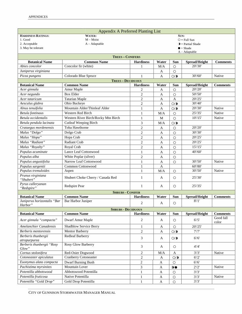
APPENDICES
CITY OF GUNNISON STORMWATER MANAGER MANUAL
Appendix A Preferred Planting List HARDINESS RATINGS: WATER: SUN: 1. Good M – Moist , = Full Sun 2. Acceptable A – Adaptable - = Partial Shade 3. May be tolerant + = Shade A – Adaptable
TREES – CONIFERS Botanical Name Common Name Hardiness Water Sun Spread/Height Comments
Abies concolor Concolor fir (white) 1 M/A , 20'/30' Juniperus virginiana A , Picea pungens Colorado Blue Spruce 1 A ,/- 30'/60' Native
TREES – DECIDUOUS Botanical Name Common Name Hardiness Water Sun Spread/Height Comments Acer ginnala Amur Maple 2 A , 20'/20' Acer negundo Box Elder 2 A , 50'/50' Acer tataricum Tatarian Maple 2 A A 20'/25' Aesculus glabra Ohio Buckeye 2 A ,/- 30'/40' Alnus tenuifolia Mountain Alder/Thinleaf Alder 1 A ,/- 20'/30' Native Betula fontinaus Western Red Birch 1 M/A , 25'/35' Native Betula occidentalis Western River Birch/Rocky Mtn Birch 1 M , 10'/15' Native Betula pendula lacinata Cutleaf Weeping Birch 3 M/A ,/- Crataegus mordenensis Toba Hawthorne 2 A , 20'/20' Malus “Dolgo” Dolgo Crab 2 A , 30'/30' Malus “Hopa” Hopa Crab 2 A , 20'/25' Malus “Radiant” Radiant Crab 2 A , 20'/25' Malus “Royalty” Royal Crab 2 A , 15'/15' Populus acuminate Lance Leaf Cottonwood 1 A , 40'/60' Populus alba White Poplar (silver) 2 A , Populus angustifolia Narrow Leaf Cottonwood 1 A , 30'/50' Native Populus sargentii Common Cottonwood 1 A 60'/80' Populus tremuloides Aspen 1 M/A , 30'/50' Native Prunus virginiana “Shubert” Shubert Choke Cherry / Canada Red 1 A , 25'/30'
Pyrus calleryanan “Redspire” Redspire Pear 1 A , 25'/35'
SHRUBS - CONIFER Botanical Name Common Name Hardiness Water Sun Spread/Height Comments Juniperus horizontalis “Bar Harbor”
Bar Harbor Juniper 2 A , 8'/1'
SHRUBS - DECIDUOUS Botanical Name Common Name Hardiness Water Sun Spread/Height Comments
Acer ginnala “compacta” Dwarf Amur Maple 2 A , 6'/5' Good fall color
Amelanchier Canadensis Shadblow Service Berry 1 A , 20'/25' Berberis mentorensis Mentor Barberry 2 A ,/- 7'/7' Berberis thunbergii atropurpurea
Redleaf Barberry 3 A ,/- 6'/6'
Berberis thunbergii “Rosy Glow”
Rosy Glow Barberry 3 A , 4'/4'
Cornus stolonifera Red-Osier Dogwood 2 M/A A 3'/3' Native Cotoneaster apiculatus Cranberry Cotoneaster 2 A ,/- 6'/2' Euonymus alata compacta Dwarf Burning Bush 2 A , 6'/6' Pachistima myrsinites Mountain Lover 3 A -/+ 2'/2' Native Potentilla abbotswood Abbotswood Potentilla 1 A , 3'/3' Potentilla fruticosa Native Potentilla 1 A , 3'/3' Native Potentilla “Gold Drop” Gold Drop Potentilla 1 A , 3'/3'

APPENDICES
CITY OF GUNNISON STORMWATER MANAGEMENT MANUAL
SHRUBS – DECIDUOUS (CONTINUED) Botanical Name Common Name Hardiness Water Sun Spread/Height Comments Potentilla “Jackmanni” Jackman Potentilla 1 A , 4'/4' Potentilla “Kathryn Dykes” Kathryn Dykes Potentilla 1 A , 4'/3' Potentilla “Mt. Everest” Mt. Everest Potentilla 1 A , Prunus cistena Purple Leaf Plum 1 A , 6'/8' Prunus tomentosa Nanking Cherry 1 A , 12'/10' Rhus typhina Staghorn Sumac
2 A , 15'/25'
Nice fall color, yellow, orange, red
Ribes alpinum Alpine Current 1 A ,/- 6'/6' Rubus deliciosus Thimbleberry 1 A A 6'/6' Native Salix purpurea nana Dwarf Arctic Willow 1 M/A ,/- 6'/6' Salix purpurea pendula Blue Fountain Willow 1 M/A ,/- 12'/8' Sambucus canadensis aurea
Golden Elderberry 2 M/A , 12'/12'
Sambucus pubens Red Elderberry 1 M/A ,/- 12'/12' Spirea bumalda “Anthony Waterer”
Anthony Waterer Spirea 2 A ,/- 4'/3'
Spirea bumalda froebeli Froebel Spirea 3 A ,/- 4'/4' Spirea nipponica Snowmound Spirea 2 A ,/- 5'/5' Spirea vanhouttei Vanhoutte Spirea 2 A ,/- 8'/6' Symphoricarpos oreophilus Mt. Snowberry 1 A ,/- 4'/4' Native
FLOWERS - PERENNIALS
BOTANICAL NAME COMMON NAME HARDINESS WATER SUN SPREAD/HT. FLOWER COLOR
BLOOM TIME NATIVE
Alyssum montanum Basket of Gold 1 A , 18'/12' mustard yellow mid spring
Aquilegia caerulea Rocky Mt Columbine 1 A -/+ 18"/24" blue w/ white center summer X
Aquilegia x “Mckana” Mckana’s Columbine 1 A A 18"/24" Various spring-summer
Astilbe False Spirea 2 A -/+ 2'/2' White Late spring Campanula calycanthema Cup and Saucer 2 A ,/- 1'/2' Various Summer
Cerastium fontanum Mouse Ear 1 A ,/- 10"/10" White Spring-summer X
Chrysanthemum coccineum
Pyrethrum/Painted Daisy 1 A , 18"/24" Various Late spring-
summer
Chrysanthemum maximum Shasta Daisy 1 A , 2'/3' White Summer Convallaria majalis Lily of the Valley 1 M -/+ 15"/12" White Late spring
Coreopsis lanceolata Lance-leaf Coreopsis 1 A , 2'/2' Yellow Early-mid summer
Coreopsis tinctoria Plains Coreopsis 1 A , 15"/15" Yellow w/ red center Mid summer
Delphinium elatum Larkspur 1 A , 3'/5' Various Summer Dianthus Dianthus 1 A , 12"/12" Various Mid summer
Dianthus barbatus Sweet William 1 A , 1'/2' Various Spring-summer
Dicentra “Luxuriant” Fringed Bleeding Heart 1 A + 18"/18" Dark pink Late spring-
early summer
Dicentra spectabillis Old Bleeding Heart 1 A + 2'/3' Pink Late spring-
early summer
Digitalis grandiflora Floxglove 1 M/A ,/- 18"/30" Yellow, pink, white
Late spring– early
summer
Doronicum cordatum Leopard’s Bane 2 M ,/- 18"/24" Yellow Spring Erigeron speciosus Fleabane 1 A , 2'/2' White Summer X Gentiana septemfida Crested Gentian 1 M/A -/+ 1'/1' Dark blue Late spring

APPENDICES
CITY OF GUNNISON STORMWATER MANAGER MANUAL
FLOWERS - PERENNIALS
BOTANICAL NAME COMMON NAME HARDINESS WATER SUN SPREAD/HT. FLOWER COLOR
BLOOM TIME NATIVE
Hosta “Royal Standard” Plantain Lily, Royal Standard 1 A + 2'/2' White Late summer
Hosta sieboldiana “elegans”
Plantain Lily, Blue Giant 1 A -/+ 3'/3' White-lavender Late summer
Hosta undulata “Variegata”
Plantain Lily, white rimmed 1 A + 18"/24" Pale lavender Mid summer
Iberis sempervirens Candytuft 1 A , 2'/1' White Late spring-
early summer
Iris kaempferi Japanese Iris, purple 2 M , 18"/36" Purple Early-mid summer
Kniphofia uvaria Red-Hot-Poker 1 D , 2'/3' Orange/yellow Mid-late summer

APPENDICES
CITY OF GUNNISON STORMWATER MANAGEMENT MANUAL