three-bit representation of three-dimensional range data
TRANSCRIPT

Three-bit representation of three-dimensionalrange data
Nikolaus Karpinsky, Yajun Wang, and Song Zhang*Department of Mechanical Engineering, Iowa State University, Ames, Iowa 50011, USA
*Corresponding author: [email protected]
Received 20 November 2012; revised 5 March 2013; accepted 5 March 2013;posted 6 March 2013 (Doc. ID 180229); published 4 April 2013
Our previous research has shown that 3D range data sizes can be substantially reduced if they areconverted into regular 2D images using the Holoimage technique. Yet, this technique requires all 24 bitsof a standard image to represent one 3D point, making it impossible for a regular 2D image to carry 2Dtexture information as well. This paper proposes an approach to represent 3D range data with 3 bits,further reducing the data size. We demonstrate that more than an 8.2∶1 compression ratio can beachieved with compression root-mean-square error of only 0.34%. Moreover, we can use another bitto represent a black-and-white 2D texture, and thus both 3D data and 2D texture images can be storedinto an 8 bit grayscale image. Both simulation and experiments are presented to verify the performanceof the proposed technique. © 2013 Optical Society of AmericaOCIS codes: 120.2650, 100.5070, 100.6890.
1. Introduction
Advancements in real-time 3D scanning are beingmade at an unprecedented rate, driving the technol-ogy further into mainstream life, as can be seen fromreal-time 3D scanners, such as the Microsoft Kinect[1,2]. With these advancements, large amounts ofdata are being generated, bringing forth the chal-lenge of streaming and storing this information inan efficient manner. Classical geometry compressionapproaches compress the 3D geometry and its attrib-utes, such as normals, texture coordinates, etc., in amodel format such as OBJ, PLY, or STL. Thoughthese formats work well for static scans or structuredmeshes, the same does not hold true for 3D scansfrom a real-time 3D scanner due to its unstructurednature [3].
To address this challenge, newer approaches bet-ter suited to data coming from 3D scanners havebeen developed, including heuristic-based point-cloud encoding [4,5] and image-based encoding ap-proaches [6–8]. Image-based encoding approaches
work well, as the geometry can be projected into im-ages, and then 2D image compression can be utilizeduntil 3D reconstruction is desired. Since 2D imagecompression is a long studied field, high compressionratios with relatively low amounts of error can beachieved.
Holoimage [8] is an image-based encoding tech-nique that allows for real-time encoding anddecoding at high compression ratios. It leveragestechniques from optical metrology, namely fringeprojection. Due to the error tolerance in fringe projec-tion, the fringe patterns can be highly compressedwith little error to the reconstructed 3D geometry.Karpinsky and Zhang [9] proposed to utilize theHoloimage technique and Hou et al. [10] proposeda similar virtual structured light technique to com-press 3D geometry. Based on Holoimage’s real-timeencoding and decoding, it is able to compress datafrom real-time 3D scanners [3]. With these merits,it is well suited as a format for high-speed 3D scans,which can then be streamed and stored.
Although Holoimage is a good technique for com-pressing 3D geometry from a real-time 3D scanner,it still uses 24 bits to represent a 3D coordinate,which in practice takes up the three standard image
1559-128X/13/112286-08$15.00/0© 2013 Optical Society of America
2286 APPLIED OPTICS / Vol. 52, No. 11 / 10 April 2013

channels [red, green, and blue (RGB)]. With this rep-resentation, there is no room in a standard image forother information, such as a texture or a normal map.This research addresses this by representing theimage with only 3 bits instead of 24 through theuse of image dithering. This leaves 21 remaining bitsfor other information, such as texture or normalmaps, allowing for more information to be storedand streamed. With this new encoding, compressionratios of 8.1∶1 have been achieved when comparedwith a 24 bit Holoimage with a mean-squared errorof 0.34%.
Section 2 explains the principle behind Holoimage,applying image dithering, and how it fits into theHoloimage pipeline. Section 3 shows experimentalresults of a 3D unit sphere and a David bust and dis-cusses the findings. Finally, Section 4 summarizesthe paper.
2. Principle
A. Holoimage Encoding and Decoding
Holoimage is a form a 3D geometry representationthat is well suited to quickly and efficiently compress3D geometry coming from 3D scanners [9]. It works
off of the principle of fringe projection from opticalmetrology. Encoding works by creating a virtualfringe projection system and virtually scanning 3Dgeometry into a set of 2D images that can then laterbe used to decode back into 3D. Figure 1 shows a con-ceptual model of the holovideo system. The projectorprojects a pattern onto the geometry, which can bedone using OpenGL shaders [3], and then the cameracaptures the resulting scene, which can be done bysaving the framebuffer as an image. Once in theimage format, standard 2D image-processing tech-niques, such as compression or dithering can beapplied.
Details of the holoimaging encoding and decodingalgorithms have been thoroughly discussed in [3]; weonly briefly explain these algorithms here. The Holo-image encoding colors the scene with the structuredlight pattern. To accomplish this, the model viewmatrix of the projector is rotated around the z axisby some angle (e.g., θ � 30°) from the camera matrix.Each point is colored with the following threeequations:
Ir�x; y� � 0.5� 0.5 sin�2πx∕P�; (1)
Fig. 1. (Color online) Holovideo system conceptual model. The virtual projection system projects sinusoidal fringe patterns onto theobject; the result is rendered by the graphics pipeline, and then displayed on the screen. The screen view acts as a virtual camera imagingsystem. Because both the projector and the camera are virtually constructed, they can both be orthogonal devices. The angle between theprojection system and the camera imaging system is θ.
10 April 2013 / Vol. 52, No. 11 / APPLIED OPTICS 2287

Ig�x; y� � 0.5� 0.5 cos�2πx∕P�; (2)
Ib�x; y� � S · Fl�x∕P� � S∕2� �S − 2�∕2· cos�2π · Mod�x; P�∕P1�; (3)
where P, the fringe pitch represents the number ofpixels per fringe stripe, P1 � P∕�K � 0.5� is the localfringe pitch andK is an integer number, S is the stairheight in the grayscale intensity value, Mod�a; b� isthe modulus operator to get a over b, and Fl�x� isused to obtain the integer number of x by removingthe decimals.
Decoding the resulting Holoimage is more involvedthan encoding involving fourmajor steps: (1) calculat-ing the phase map from the Holoimage frame, (2)filtering the phase map, (3) calculating normals fromthe phase map, and (4) performing the final render. Amultipass rendering was utilized to accomplish thesesteps, saving results from the intermediate steps to atexture, which allowed us to access neighboring pixelvalues in proceeding steps.
Equations (1)–(3) provide the phase uniquely foreach point,
Φ�x; y� � 2π × Fl��Ib − S∕2�∕S�� tan−1��Ir − 0.5�∕�Ig − 0.5��: (4)
It should be noted that this phase is already un-wrapped, and thus no spatial phase unwrapping isrequired for this process. From the unwrapped phase�x; y�, the normalized coordinates �xn; yn; zn� can bedecoded as [9]
xn � j∕W; (5)
yn � i∕W; (6)
zn � PΦ�x; y� − 2πi cos�θ�2πW sin θ
: (7)
This yields a value zn in terms of P, which is thefringe pitch, i, which is the index of the pixel beingdecoded in the Holoimage frame, θ, which is theangle between the capture plane and the projectionplane (θ � 30° for our case), and W, which is thenumber of pixels horizontally.
From the normalized coordinates �xn; yn; zn�, theoriginal 3D coordinates can recovered point by point:
x � xn × Sc � Cx; (8)
y � yn × Sc � Cy; (9)
z � zn × Sc � Cz: (10)
Here Sc is the scaling factor to normalize the 3Dgeometry, and (Cx, Cy, and Cz) are the center coordi-nates of the original 3D geometry.
B. Image Dithering
Image dithering is the process of taking a highercolor depth image and reducing the color depth toa lower level through a quantization technique[11]. Different types of image-dithering techniquesexist, such as ordered dithering [12] and error diffus-ing [13]. In this research, two of the most popularalgorithms were investigated: Bayer [12] andFloyd–Steinberg [14] dithering.
1. Bayer DitheringBayer dithering, sometimes known as ordered dith-ering, involves quantizing pixels based on a thresh-old matrix [12]. In the simple case of quantizing to abinary image, it involves taking each pixel in an im-age and applying Algorithm 1:
Algorithm 1: Bayer dithering
Input: Pixel—Structure representing properties of a pixel inan image. Has color components ranging from 0.0 to 1.0
Input: ThresholdMap—Matrix of threshold valuesOuput: Pixel.color—Pixel’s dithered color component,
either 0 or 1for Each Pixel do
if Pixel:color >� ThresholdMap�pixel:xmod map Width��pixel:ymod mapHeight�
thenPixel:color � 1;
elsePixel:color � 0;
endend
M � 4.0255.0
�
266666666664
0 32 8 40 2 34 10 4248 16 56 24 50 18 58 2612 44 4 36 14 46 6 3860 28 52 20 62 30 54 223 35 11 43 1 33 9 4151 19 59 27 49 17 57 2515 47 7 39 13 45 5 3763 31 55 23 61 29 53 21
377777777775:
(11)
Equation (11) gives an example of an 8 × 8 thresh-old matrix, which was also the matrix used inthis work.
Bayer has shown that if the sizes of the matricesare 2N (N is an integer), then optimal matricescan be derived; the matrices can be obtained asfollows:
M1 ��0 23 1
�; (12)
2288 APPLIED OPTICS / Vol. 52, No. 11 / 10 April 2013
which is the smallest 2 × 2 base dither pattern.Larger dither patterns can be obtained using
Mn�1 ��
4Mn 4Mn � 2Un
4Mn � 3Un 4Mn �Un
�; (13)
where Un is an n-dimensional unit matrix (onefor all elements). Using larger threshold matricesallows more distinct tones to be represented inthe final image; thus larger threshold matricescould result in lower error. In this research, weused an 8 × 8 since it is a large matrix that shouldtheoretically yield 64 different tones in the result-ing image. However, we also found that if thematrix is too large, the resultant dithered patternis not of high quality. We typically use 8 × 8 or16 × 16 matrices of our study.
With Bayer dithering, the threshold map addsminor local error noise to the quantized pixel, butthe overall intensity is preserved. Since thisalgorithm is a parallel algorithm, it can easily beintegrated into the Holoimage pipeline in thefragment shading stage of the encoding, allowingfor little to no overhead in encoding.
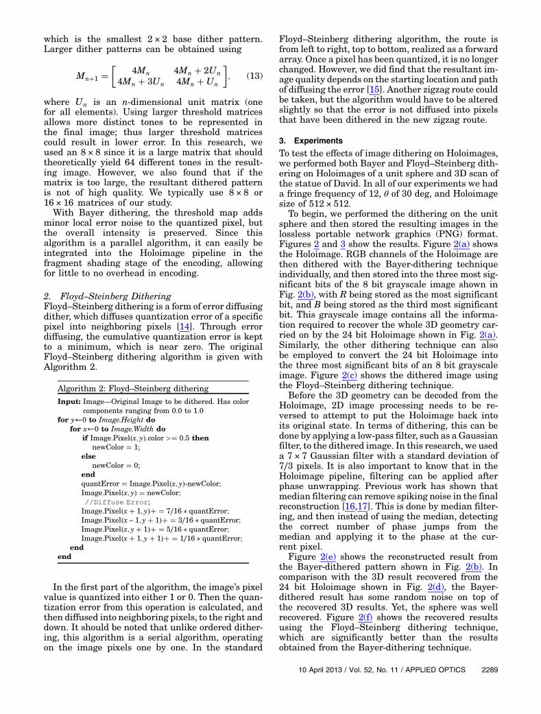
2. Floyd–Steinberg DitheringFloyd–Steinberg dithering is a form of error diffusingdither, which diffuses quantization error of a specificpixel into neighboring pixels [14]. Through errordiffusing, the cumulative quantization error is keptto a minimum, which is near zero. The originalFloyd–Steinberg dithering algorithm is given withAlgorithm 2.
Algorithm 2: Floyd–Steinberg dithering
Input: Image—Original Image to be dithered. Has colorcomponents ranging from 0.0 to 1.0
for y←0 to Image.Height dofor x←0 to Image.Width do
if Image:Pixel�x; y�:color >� 0.5 thennewColor � 1;
elsenewColor � 0;
endquantError � Image:Pixel�x; y�-newColor;Image:Pixel�x; y� � newColor;//Diffuse Error;Image:Pixel�x� 1; y�� � 7∕16 � quantError;Image:Pixel�x − 1; y� 1�� � 3∕16 � quantError;Image:Pixel�x; y� 1�� � 5∕16 � quantError;Image:Pixel�x� 1; y� 1�� � 1∕16 � quantError;
endend
In the first part of the algorithm, the image’s pixelvalue is quantized into either 1 or 0. Then the quan-tization error from this operation is calculated, andthen diffused into neighboring pixels, to the right anddown. It should be noted that unlike ordered dither-ing, this algorithm is a serial algorithm, operatingon the image pixels one by one. In the standard
Floyd–Steinberg dithering algorithm, the route isfrom left to right, top to bottom, realized as a forwardarray. Once a pixel has been quantized, it is no longerchanged. However, we did find that the resultant im-age quality depends on the starting location and pathof diffusing the error [15]. Another zigzag route couldbe taken, but the algorithm would have to be alteredslightly so that the error is not diffused into pixelsthat have been dithered in the new zigzag route.
3. Experiments
To test the effects of image dithering on Holoimages,we performed both Bayer and Floyd–Steinberg dith-ering on Holoimages of a unit sphere and 3D scan ofthe statue of David. In all of our experiments we hada fringe frequency of 12, θ of 30 deg, and Holoimagesize of 512 × 512.
To begin, we performed the dithering on the unitsphere and then stored the resulting images in thelossless portable network graphics (PNG) format.Figures 2 and 3 show the results. Figure 2(a) showsthe Holoimage. RGB channels of the Holoimage arethen dithered with the Bayer-dithering techniqueindividually, and then stored into the three most sig-nificant bits of the 8 bit grayscale image shown inFig. 2(b), with R being stored as the most significantbit, and B being stored as the third most significantbit. This grayscale image contains all the informa-tion required to recover the whole 3D geometry car-ried on by the 24 bit Holoimage shown in Fig. 2(a).Similarly, the other dithering technique can alsobe employed to convert the 24 bit Holoimage intothe three most significant bits of an 8 bit grayscaleimage. Figure 2(c) shows the dithered image usingthe Floyd–Steinberg dithering technique.
Before the 3D geometry can be decoded from theHoloimage, 2D image processing needs to be re-versed to attempt to put the Holoimage back intoits original state. In terms of dithering, this can bedone by applying a low-pass filter, such as a Gaussianfilter, to the dithered image. In this research, we useda 7 × 7 Gaussian filter with a standard deviation of7∕3 pixels. It is also important to know that in theHoloimage pipeline, filtering can be applied afterphase unwrapping. Previous work has shown thatmedian filtering can remove spiking noise in the finalreconstruction [16,17]. This is done by median filter-ing, and then instead of using the median, detectingthe correct number of phase jumps from themedian and applying it to the phase at the cur-rent pixel.
Figure 2(e) shows the reconstructed result fromthe Bayer-dithered pattern shown in Fig. 2(b). Incomparison with the 3D result recovered from the24 bit Holoimage shown in Fig. 2(d), the Bayer-dithered result has some random noise on top ofthe recovered 3D results. Yet, the sphere was wellrecovered. Figure 2(f) shows the recovered resultsusing the Floyd–Steinberg dithering technique,which are significantly better than the resultsobtained from the Bayer-dithering technique.
10 April 2013 / Vol. 52, No. 11 / APPLIED OPTICS 2289

To better compare these dithering techniques,Fig. 3 shows the cross sections of the recovered 3Dresults using different methods compared with theideal unit sphere. Figures 3(a) and 3(d), respectively,show the cross section of the recovered 3D sphereoverlapping with the ideal unit sphere, and the crosssection of the difference between these two, when the24 bit Holoimage is used. The results are smooth,and the error is small, which has been demonstratedpreviously [3]. The Bayer-dithered results [Figs. 3(b)and 3(e)] show that the overall geometry was recov-ered quite well, but the error is larger: an approxi-mate root-mean-square (rms) error of 0.33%. It canbe seen that this error is still quite small. Yet, theFloyd–Steinberg dithering technique can further im-prove the results, as shown in Figs. 3(c) and 3(f). Thisis due to the quantization error being diffused intoneighboring pixels, reducing the overall quantizationerror. The error can be further reduced to have anapproximate rms error of 0.2%. Is should be notedthat only 3 bits were used to represent the 24 bitHoloimage, and the reconstructed geometry is stillof high quality.
Compression results depend on how the resultingdithered information is stored. In this work JPEGand other lossy image compression was not useddue to the fact that it makes use of a low-pass filterbefore compression. This takes the 3 bit binary dith-ered information and transforms it back into 24 bit
information, which is undesirable. Instead, PNG, alossless image compression, was utilized, and thethree most significant bits of a grayscale image wereutilized, shown by Fig. 4(a). This resulted in a filesize of 79 kB with the unit sphere. Further compres-sion can be achieved by saving the image in a planarformat, three times as wide with image channels oneafter another, and then saving the PNG as a logical1 bit image. This resulted in a file size of 62 kB, yield-ing a compression ratio of 3.9∶1 when comparedagainst a 24 bit Holoimage in the PNG format.
To further test dithering on Holoimages, the tech-nique was performed on a scan of the statue of Davidshown in Fig. 5. Figure 5(a) shows the 24 bit Holo-image, and Fig. 5(d) shows the recovered 3D geom-etry. The 24 bit Holoimage is then dithered into3 bits and stored into the three most significant bitsof an 8 bit grayscale image. Figures 5(b) and 5(c), re-spectively, show the Bayer-dithered result and theFloyd–Steinberg dithered result, and their recovered3D shapes are shown in Figs. 5(e) and 5(f). Again, itcan be seen that Bayer dithering results in largeramounts of error seen as ripples and bumps on thesurface; Floyd–Steinberg dithering has some of theseerrors as well, but they are not as prominent as in thecase with Bayer dithering. Floyd–Steinberg dither-ing results a lower rms error of 0.34% when com-pared to Bayer dithering at 0.37%. The resultingfile size is 39 kB, achieving a compression ratio of
Fig. 2. (Color online) Results of dithering on unit sphere in a lossless image format. (a) Original Holoimage, (b) Holoimage with Bayerdithering, (c) Holoimage with Floyd–Steinberg dithering, (d) 3D reconstructed results for image shown in (a), (e) 3D reconstructed resultsfor image shown in (b), and (f) 3D reconstructed results for image shown in (c).
2290 APPLIED OPTICS / Vol. 52, No. 11 / 10 April 2013

8.2∶1 when compared to the 24 bit Holoimage.Although it might be expected that a simple unitsphere would have a higher compression, this isnot the case, as PNG compression depends on pre-compression and DEFLATE steps, which can resultin different file sizes for similar images.
Since the proposed technique only requires 3 bitsto represent the whole 3D geometry, there are 21 bitsremaining to encode more information such as thegrayscale texture that comes from the 3D scanner,which can be encoded into the same image. There
are essentially two approaches to carry on texturewith 3D geometry. The first method is to pack the8 bit grayscale image directly into the 24 bit image.Figure 6(a) shows the resultant image, and its recov-ered 3D geometry with texture mapping is shown inFig. 6(b). The file size is approximately 189 kB, whichis a substantial reduction compared with the original24 bit Holoimage stored in PNG format 320 kB.
The 8 bit texture image can be dithered as well tofurther compress the data. Figure 6(c) shows thepacked image that stores the 3D geometry along with
−0.5 0 0.50
0.2
0.4
Z
X
TheoreticalObserved
−0.5 0 0.50
0.2
0.4
Z
X
TheoreticalObserved
−0.5 0 0.50
0.2
0.4
Z
X
TheoreticalObserved
−0.5 0 0.5−5
0
5x 10
−3
∆ Z
X−0.5 0 0.5−5
0
5x 10
−3
∆ Z
X−0.5 0 0.5−5
0
5x 10
−3
∆ Z
X
100 200 300 400 500
100
200
300
400
500
−0.1
−0.05
0
0.05
0.1
0.15
100 200 300 400 500
100
200
300
400
500
−0.1
−0.05
0
0.05
0.1
0.15
100 200 300 400 500
100
200
300
400
500
−0.1
−0.05
0
0.05
0.1
0.15
(a) (b) (c)
(d) (e) (f)
(g) (h) (i)
Fig. 3. (Color online) Reconstruction errors of dithering on unit sphere in a lossless image format. (a) Cross section of reconstructed resultshown in Fig. 2(d), (b) cross section of reconstructed results shown in Fig. 2(e), (c) cross section of reconstructed result shown in Fig. 2(f),(d) reconstruction error between the reconstructed and ideal unit sphere for the result in (a), (e) reconstruction error between the recon-structed and ideal unit sphere for the result in (b) (approximate rms error 0.33%), (d) reconstruction error between the reconstructed andideal unit sphere for the result in (c) (approximate rms error 0.2%), and (g)–(i) difference map of technique to ideal unit sphere.
Fig. 4. Different ways to hold a packed ditheredHoloimage. (a) Dithered channels packed in the threemost significant bits and saved as agrayscale PNG with resulting file size of 79 kB. (b) Dithered channels packed into a planar format and then saved as a logical PNG withresulting file size of 62 kB.
10 April 2013 / Vol. 52, No. 11 / APPLIED OPTICS 2291

the 1 bit dithered texture image into the four mostsignificant bits of an 8 bit grayscale image. From thisimage, the texture can be recovered by applyinga very small Gaussian filter (7 × 7) as shown inFig. 6(d). It can be seen that the texture image isof good quality. With only 4 bits, the file size isapproximately 64 kB. This example clearly demon-strates that the proposed technique can embed boththe 3D geometry and the texture into a regular 2Dimage, making it a novel technique to store 3D rangedata in a substantially reduced size, with minor lossof quality. Furthermore, because it only utilizes 4 bits,this proposed 3D range data compression techniquecan be leveraged for applications in which other
critical information, such as connectivity or bumpmaps, needs to be carried along.
4. Conclusion
An approach to represent 3D geometry has been pre-sented, specifically applying image dithering to theHoloimage technique to reduce the bit depth from24 to 3 bits. The technique was presented with twoforms of image dithering, and sample data of a unitsphere and a 3D scan of David have been shown. Amean-squared error of 0.2% was achieved on the unitsphere with a compression of 3.9∶1 when comparedwith the 24 bit Holoimage technique, and an rms er-ror of 0.34% was achieved on the scan of David with a
Fig. 5. (Color online) Results of dithering on scan of David statue in a lossless image format. (a) Original Holoimage, (b) Holoimage withBayer dithering, (c) Holoimage with Floyd–Steinberg dithering, (d) recovered 3D geometry from (a), (e) recovered 3D geometry from (b),and (f) recovered 3D geometry from (c).
Fig. 6. (Color online) Packing dithered Holoimage with texture. (a) 3 bit packed Holoimage with 8 bit grayscale texture, (b) 3D geometrywith original 8 bit texture mapping, (c) 3 bit packed Holoimage with 1 bit dithered texture, (d) 3D geometry with 1 bit dithered texturemapping, and (e) 3D geometry with 1 bit dithered texture after texture is Gaussian filtered.
2292 APPLIED OPTICS / Vol. 52, No. 11 / 10 April 2013

compression of 8.2∶1 when compared with the 24 bitHoloimage. With the remaining 21 bits, grayscaletexture information was also encoded, effectivelyembedding 3D geometry and texture into a single8 bit grayscale image. Future work for this researchincludes extending it to video with animation appro-priate dithering.
References1. G. Geng, “Structured-light 3D surface imaging: a tutorial,”
Adv. Opt. Photon. 3, 128–160 (2011).2. S. Zhang, “Recent progresses on real-time 3-D shapemeasure-
ment using digital fringe projection techniques,” Opt. LasersEng. 48, 149–158 (2010).
3. N. Karpinsky and S. Zhang, “Holovideo: real-time 3D video en-coding and decoding on GPU,” Opt. Lasers Eng. 50, 280–286(2012).
4. B. Merry, P. Marais, and J. Gain, “Compression of dense andregular point clouds,” Comput. Graph. Forum 25, 709–716(2006).
5. S. Gumhold, Z. Kami, M. Isenburg, and H.-P. Seidel, “Predic-tive point-cloud compression,” in ACM SIGGRAPH 2005Sketches (ACM, 2005), pp. 137–141.
6. X. Gu, S. J. Gortler, and H. Hoppe, “Geometry images,” ACMTrans. Graph. 21, 355–361 (2002).
7. R. Krishnamurthy, B. Chai, and H. Tao, “Compression andtransmission of depth maps for image-based rendering,” inProceedings of 2001 International Conference on ImageProcessing (IEEE, 2001), pp. 828–831.
8. X. Gu, S. Zhang, P. Huang, L. Zhang, S.-T. Yau, and R. Martin,“Holoimages,” in Proceedings of the 2006 ACM Sympo-sium on Solid and Physical Modeling (ACM, 2006),pp. 129–138.
9. N. Karpinsky and S. Zhang, “Composite phase-shifting algo-rithm for three-dimensional shape compression,” Opt. Eng.49, 063604 (2010).
10. Z. Hou, X. Su, and Q. Zhang, “Virtual structured-light codingfor three-dimensional shape data compression,” Opt. LasersEng. 50, 844–849 (2012).
11. T. L. Schuchman, “Dither signals and their effect on quanti-zation noise,” IEEE Trans. Commun. Technol. 12, 162–165(1964).
12. B. Bayer, “An optimum method for two-level rendition ofcontinuous-tone pictures,” in IEEE International Conferenceon Communications (IEEE, 1973), pp. 11–15.
13. T. D. Kite, B. L. Evans, and A. C. Bovik, “Modeling and qualityassessment of halftoning by error diffusion,” in IEEEInternational Conference on Image Processing (IEEE, 2000),pp. 909–922.
14. R. W. Floyd and L. Steinberg, “An adaptive algorithmfor spatial gray scale,” J. Soc. Inf. Disp. 17, 75–77(1976).
15. W. Lohry and S. Zhang, “Genetic method to optimize binarydithering technique for high-quality fringe generation,” Opt.Lett. 38, 540–542 (2013).
16. N. Karpinsky and S. Zhang, “3D video compression with theH.264 codec,” Proc. SPIE 8290, 829012 (2012).
17. M. McGuire, “A fast, small-radius GPU median filter,”ShaderX6: Advanced Rendering Techniques (Charles RiverMedia, 2008).
10 April 2013 / Vol. 52, No. 11 / APPLIED OPTICS 2293