three-dimensional analysis of rail track structure
TRANSCRIPT

Three-Dimensional Analysis of Rail Track Structure David J. Turcke and (Jerald P. Raymond, Department of Civil Engineering, Queen's
University, Kingston, Ontario
A three-dimensional finite-element model of a railway track structure that includes rails, ties, and ballast is described. The material proper· ties used for the cohesionless ballast and subballast are obtained from triaxial tests. A nonlinear, incremental numerical procedure based on a bicubical-spline stress-strain approximation is being developed for use in the finite-element analysis. At present, the program is capable of linear analysis only. The behavior of the track structure under static loading is predicted by using the I inear analysis. Comparison is made between different ballast geometries on both typical sand and clay subgrades. The results show the potential value of a nonlinear analysis.
The increased speeds, higher traffic densities, and larger and heavier cars now being used on railroads have led to new requirements for improved stability and durability of rail track support. The impact of research and development in the area of track structure design and maintenance could be large; the costs associated with the replacement and upkeep of railroad fills are estimated to be about $100 million/year for Canadian railroads alone. A large portion of this cost is due to geotechnical problems.
To reduce these costs, the rail track structure must be improved so as to minimize both live-load deformations and permanent settlements. The solution to this problem depends on a large number of variables. These include, for example, the density, grading, and type of ballast; the shape of the particles; the dimensions of various layers; the water content in the lower layers; the type of subgrade; tie spacing; rail weight; and the magnitude and speed of wheel loads.
One approach to better understanding of the behavior of the rail track structure is the use of sophisticated analytical techniques to model the structure. This provides the engineer with a means of studying various maintenance techniques that affect the behavior of the track system.
FINITE-ELEMENT MODEL
To effectively model the behavior of ballast and foundation material requires the use of techniques that include the effects of the stress-path dependence and nonlinearity of the continuum and of its lack of ability to sustain tension.
This paper presents the first steps of a threedimensional finite-element program-analysis of rail track structure-that is being developed (at present, only a linear model has been completed). The program described here, however, provides the user with a family of isoparametric hexahedral and pentahedral elements that are of sufficient complexity to simulate the anticipated displacements and stress fields from multidirectional static loading. Specifically, as shown in Figure 1, the program includes 8- and 20-nodal hexahedrons and 6- and 15-nodal pentahedrons.
The major properties programmed to characterize the behavior of the soil material are its stress-path dependence and its lack of ability to sustain tension. The soil elements used include ballast, subballast, and subgrade material. In addition, the elements representing the track ties may be taken as nonlinear in both tension and compression.
The first feature being incorporated-the stresspath dependence-requires an iterative step-by-step numerical procedure. The necessary constitutive relations are obtained by modeling the triaxial test results for various confining pressures by the use of bicubical splines (1). The stress or strain paths are then determined by-three-dimensional interpolation. In the current program, each set of experimental discrete data for a particular confining pressure is first smoothed by the method of least squares and then approximated by a cubic spline curve (F1) as shown in Figure 2. Given this function,
F; = f(a 1 - a3 , E 1) (i = I, 2, 3, . .. , n) (I)
where n = number of different confining pressures a~, the partial derivatives (oF 1/o E 1) are taken at points corresponding to ( lk, k = 1, 2, 3, ... , m and denoted by Fi,k) where m =user-selected number of prescribed points in the E 1 direction. (It should be noted that m need not have the same value as the number of experimental readings; once the spline F 1 is known, the spac -ing on the E 1 axis can be chosen arbitrarily.)
In the next step, the cubic splines are formulated in the 0'3 direction to give the set of functions
(2)
and their derivatives oG./o0'3 (or Gk,;). The last member of the vector [Note: in this paper, vector quantities are designated by asterisks]
(3)
where
O', = 0'1 - 0'3,
p = 0'3, O' '·' = F i,k' and O",,r = Gk,i
required for interpolation over the rectangular mesh, as shown in Figure 2, is then obtained by calculating the first derivatives of E 1 in the 0'3 direction. Given all the vectors cr;;k, the complete bicubical spline (S) is defined as shown in Figure 2, and the tangent modulus (Et = oS/0<1) can be calculated for any C73 and '"
The second feature requires modeling the lack of ability of the ballast to sustain tension. An iterative, no-tension technique by Zienkiewica and others (2) is used for this purpose. This technique is as follows:
1. If certain tensile principal stresses have developed, they are eliminated without permitting any point in the structure to displace. Then, to satisfy overall equilibrium, restraining forces equivalent to the tensile principal stresses are evaluated element by element and temporarily applied to the structure.
2. These fictitious restraining forces are then removed by applying equal but opposite nodal forces. The structure is then reanalyzed to determine any remaining tensile stresses. If these are still greater than a certain limit, steps 1 and 2 are repeated.
1

2
In summary, the overall procedure for the j th step and is as follows :
1. A small load increment is imposed, and the displacements and stresses are computed by using the tangent Young's moduli E,,J-i·
2. All tensile strP.Rses in the ballast are eliminatP.d, 3. From the total stress-strain level reached, the
new E 1,; is calculated element by element by using the bicubic spline S, and the new global stiffness matrix for the structure is then computed.
4. If the total number of increments has not been reached, repeat steps 1-3; otherwise, stop.
The finite-element computer program being developed will be able to calculate the contact stresses . The theory used to obtain the contact stresses is as follows: If the external load acting on the tie is denoted by Q*, the contact stress by p(x, y), the equivalent force vector top by P~ the stiffness matrix of the tie (oranarbitrary body in contact .for that matter) by Kf, and the stillness ~tdx of the track bed by Kt.'", then the stiffness equations for the tie and the track bed separately are
Figure 1. Family of three-dimensional elements.
8 NODED HEXAHEDRON 20 NODED HEXAHEORON
6 NODED PENTAHEDRON 15 NODED PENTAHEDRON
Figure 2. Determination of stress-strain surface by use of cubic spline.
10
(4)
(5)
where
w1f, wr = displacements of the tie and the track bed, respectively, and
wt, w~fc = corresponding displacements of the contact area.
The total structural system is then
(6)
Once this system is solved, the nodal forces (P*) equivalent to the contact pressure can be calculated by using Equation 5. The conta ct stress [ p(x, y )J can then be de -termined by using the principle of equivalent work
P* x wf" T =f p(x,y) x v(x,y)dA A
(7)
where v(x, y) = deflection of the contact area. If p(x, y) is app o · :n.ated by th same shape-function row matrix N as v(x,y), then, because v(x,y) = N*v*r , p.(x,y) = N*pr. Therefore ,
P*x wfcT= p/ NH x N*x dA x vH A
and, by using the compatibility condition that
Equation 7a becomes
P* = p* x M*
where
M* = f N*T x N*dA A
(7a)
(7b)
and thus p* = M*- 1 x P and finally p(x, y) = N* x p\ which represents the continuous contact stress function.
Equation 6 holds for the bonded contact between the tie and the ballast. However, field results, as well as a simple observation of an actual rail track, show that the track bed does not settle uniformly. Settlements underneath the rail and under the tie ends are greater than those under the central portion of the tie. This is well known by railroad companies, because failure to maintain the track causes the ties to break along the track centerline. A currently used practical solution to this problem is to leave the central portion of the ballast bed uncompacted and compact only the ballast under the rails . This solution, however, does not appear to be the most efficient one. Uneven settlements due to uneven compaction cause separation of the contact between a tie and the ballast. Mathematically, this means that the contact contour is not known and is dependent on the relative stiffnesses of the tie and the ballast foundation . Although the tie stiffness is fairly constant, the stiffness of the ballast is dependent on the local density and varies across the track bed. Thus , in Equation 6, wf
0 is not equal to wfc everywhere under
the tie. However, the approximate contact contour can be determined by iterative analysis. In such an analysis,

the contact between the tie and the ballast is determined by a step-by-step procedure for all the contact points that transmit tensile bonding forces. As has been shown by Svec @.), this method is simple and usually converges quickly. The only care r equired is that the contact area must be reduced by a logical procedure so that contact islands are not created.
A few useful additional features of this program should be mentioned. First, because the boundary conditions are imposed at the elemental level before the assembly of the total Kif and K1f stiffness matrices takes place, the total number of equations is reduced by up to 40 percent, depending on the mesh and boundary conditions. Second, the half band of these matrices are further divided and stored on a disk pack; direct access files are used for the assembly and sequential files are used for solving. Third, the advanced solver program developed by Wilson and others (!) was used in the program.
MATHEMATICAL MODEL FOR EXAMPLES
The finite-element model shown in Figure 3 was used to investigate various effects on the response of a linear elastic soil. This model is based on Canadian main-line railroad practice, which involves the use of 68-kg/m (136-lb/yd) continuous welded rail on 150-mm (6-in) deep by 200-mm (8-in) wide by 2.44-m (8.0-ft) long ties at 500-mm (20-in) center-to-center spacing. The ballast and subballast depths were varied from model to model; however, the shoulder at the top of the tie was taken as 150 mm, and the side slope of the ballast was fixed at a horizontal to vertical ratio of 2: 1. Because only vertical loading was investigated, the ballast elements above the base of the ties were omitted to reduce computer computation time and charges.
The simulated loading was that of a series of E60 Cooper locomotives that has three axle bogies on adjoining locomotives spaced at approximately 8.2 m (27 ft) center to center. To reduce the amount of computation, mirror vertical faces (or shearless vertical planes) were assumed below the central axle of the bogie, below the coupler between two locomotives, and along the centerline of the track. Because the model requires that the loads be applied at nodes, the dimensions were modified where necessary so that the loads were approximately correctly positioned. The axle load for an E60 Cooper locomotive was taken as 287 kN (64 500 lbf). In addition, the effect of a bogie having a single axle at the same loading was investigated.
The elastic properties of the soil, which were taken as constant, are given below (1 MPa = 145 lbf/in2
).
Material E (MPa) v -
Rail 206 897 Tie 11 724 0.30 Ballast 300 0.45 Subballast 100 0.45 Sand subgrade 100 0.45 Clay subgrade 20 0.45
Figure 3. Finite-element track model .
72kN AT 144kN AT z NODE 10 NODE 235 y~x 68 kg/m RAIL
TIE~-· · -I · - -'y; _ .. _ ;_~: '..-. :'~; +::=:-BALLAST . _ r::,. ;;::"( :::::::·<;:::: ~· ., .. .. ~ .. ~ .... .. .
SUBBALLAST '- • . : • : •• : ', ~ • , •, •
SUBGRADE / • - ' ' . . l ... .. l • I I I 1 i t ..
The various track support sections analyzed are given below (1 mm= 0.039 in).
Ballast Subballast Depth Depth (including sand
Case (mm) subgrade) (mm)
1 150 1200 2 300 600 3 300 300 4 300 150 5 450 600 6 450 1200 7 300 750 8 450 750
COMPARISON OF EFFECTS OF SINGLE-AXLE LOAD AND THREE-AXLE BOGIE
Clay Subgrade Depth (mm)
0 900 900 900 900
0 900 900
3
The effects of a single-axle load versus a three-axle bogie were compared by using the finite-element model shown in Figure 3 and the ballast and subgrade depths shown above for cases 1, 2, 5, 7, and 8. The increase in vertical stress and displacement caused by the three axles at the tie-ballast interface below the rail and the central axle and the increase in horizontal displacement at the subballast-subgrade interface are given below (the locations chosen are points of the maximum value).
Increase (%)
Vertical Horizontal Vertical Stress Displacement Displacement
Case at Node 9 at Node 9 at Node 7
1 30 18 55 2 37 43 62 5 29 41 56 7 34 41 53 8 28 42 65
From case 1, which is the only one involving a sand subgrade, it can be seen that the increase in vertical deformation is the least of all the cases considered. This agrees with the simple theory normally used of a beam on an elastic foundation (i.e., constant coefficient of subgrade reaction), where an increasing coefficient of subgrade reaction causes a decrease in axle or wheel interaction. Figure 4 shows the vertical displacement across the loaded centerline section, which again demonstrates that the increased deflection due to axle interaction is small.
The horizontal displacements across the loaded centerline section for case 1 are shown in Figure 5. It is apparent that the effect of adding two outer axles is to reduce the longitudinal deformations in the direction of the rails near the central load and thus increase the lateral deformations perpendicular to the rail. It can be seen that the increase in lateral deformations of about 50 percent are general across the whole section.
When the subgrade is soft clay, the vertical deformations are increased (as would be expected by the low coefficient of subgrade reaction used in the beam-onelastic-foundation theory because the effect of axle interaction is increased). The uniformity of the verticaland lateral-deformation increases are demonstrated on the central cross-sections by the results obtained for case 2 (see Figures 6 and 7). As noted, the magnitude of the differences on a clay subgrade (Figure 6) are greater than those on sand (Figure 4). The percentage increases of the lateral deformations are similar, although the magnitudes are obviously greater for the clay subgrade .

4
Figure 4. Transverse vertical deformation below central tie: case 1.
INITIAL VALUES E 1 =11,700 MPa E 2 300 MPo E 3 IOOMPo
72 kN
••
--- DEFLECTIONS FROM ONE CONCENTRATED LOAD
-- DEFLECTIONS FROM TWO CONCENTRATED LOADS
Ei ' - ---- - ----10 --~ Io.25mm
E:r=--=-=-=.::-=-;.;;,;;-o.=:-==-~-~'- r-:'"""~___.-:;_l'~·r~~-~-~-::;::::===;1~9~~~~~:=:::::=:::::::=::~~ 3 -------- -----~ - - ~.........-- 18 2..2. ••
12 17
Figure 5. Transverse horizontal deformation below central tie: case 1.
INITIAL VALUES E 1 =11,700MPo 72 kN E 2 300MPo ~ 3 IUUMPo
- - - DEFLECTIONS FROM ONE CONCENTRATED LOAD
~- DEFLECTIONS FROM TWO CONCENTRATED LOADS
E1 •i---------"""'----;,;1-'<'1:-------;,,,.._.
Ez
I I I I I I
I t
Figure 6. Transverse vertical deformation below central tie: case 2.
INITIAL VALUES --- DEFLECTIONS FROM E 1=11,700 MPo 72 kN
E 2 = 300 MPo ONE CONCCNTRATCD LOAD
E 3 = 100 MPo E 4 20 MPo . .....:-----~""" .... __ _..,
-- DEFLECTIONS FROM TWO CONCENTRATED LOADS
E' •1-------...... ---°"""'"f----~~ E, --- ----------- --
~"""""""""...,"""'""'~::E::.:..:'.=-=:::o....!i!ji:::=----!!i---:-::-=~~---===="i
" " •• -------- ----- -----
1 g 11 16. to n ~ ~ ,11"-~ii1 ""' ~ '1<1~,~~l1\'\."'1i~§~~':.•"'.\.~""' - ~$J~'-)\~-,;1,,'.,;;.;:...~,~>r,....,\.)'V.,\;r,\\,J~\"~,~~\.
Figure 7. Transverse horizontal deformation below central tie: case 2.
--- DEFLECTIONS FROM INITIAL VALUES
E 1=11,700 MPn 72 kN E 2 = 300 MPo
ONt CONCtNTHATtlJ LUAlJ
-- DEFLECTIONS FROM E3= IOOMPo E4 20 MPa TWO CONCENTRATED LOADS
• E,
' I I
' ' I I I
' 1 ' ' ' I
' I
12
COMPARISON OF EFFECTS OF DIFFERENT DEPTHS OF SUBBALLAST ABOVE CLAY
0.25 mm
ll ,.
••
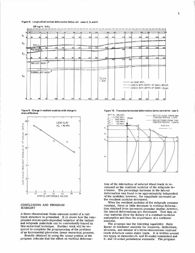
The comparison of the results of cases 2, 3, and 4 allows a direct measure of the effect of increases in subballast (or ballast) depth above a clay subgrade, assuming no change due to confinement or decrease in shear stress in the clay properties. The effect of added granular cover under these conditions is negligible, as demonstrated by the vertical settlements below the rail vertical section (see Figure 8). However, in a real situation, it is to be expected that the elastic properties of a clay subgrade would change as the confinement and shear stresses changed. As shown in Figure 9, which illustrates the change in resilient modulus obtained by Raymond and ot)lers @ .for a triaxial sample of clay at a confuting p.ressure of 3 5 kPa (5 lbf/ in2
), there is conside1·able change 01 resilient modulus as the stress difference changes. In addition, added granular depth will also increase the confining pressure. {These effects will warrant investigation when the nonlinear portion of the program is avail-able, as will consideration o.f the decrease in shear stress and of the small increase in confining pressure due to ballast widening rather than increasing depth.)
Even if the elastic properties of the subgrade remain constant as the granular depth increases, there is nevertheless an improvement in lateral clefnrmati.nns. This is apparent .from a comparison of the horizontal displacements for case 4 (see Figure 10) with those for case 2 (Figure 7). How important this reduction in lateral deformations is in reducing deterioration under repeated loading (i.e., that due to the passage of large numbers of wheel loads) is unknown. However, it is not unreasonable to suspect that the larger the deformation, the greater the adverse effect in terms of the fatigue life of the whole support system. In particular, the overlying granular material, which generally has a much higher resilient modulus than clay, can be expected to be adversely affected because of the incompatibility of strains at the ballast-clay interface.
5
Figure 8. Longitudinal vertical deformation below rail: cases 2, 3, and 4.
68 kg/m RAIL I':" - - ·- - - · - - - - - - - - - - - - -- - - - - - - - - -
IC~ -------- -,
i"-1 •. _____ !C),......___m~---!.iL___.lJ~"""-- .JG;Q____!O~ ---.!IO_fil _ ____ .,!60
~ «l
" B!..~-- -Jj~3!__~ -~JoB.!..~--- :!'I~
• "' ~· 94 109 134 15' 184 205 234 Z59 284 30' 33.q 359 384 4 09 43'1
~ -RAIL-., ~
8 ~ A' 10' 133 1~ ,., ""' ,.; --- .
""" ... .. , 4 n< 4" R°IEBA~ ... -=- JCI
r -.12 ~· 82 10' ll' 151 182 zw z~z :iti1 3"7 '82 40 432
~ ,~ 301 33'
- BALLAST BASE- l.I ~~ ~.:. - ' - -- -- ~~z:r"'lll
--=~--~
-=-- !:-=-=.:... ___ - ~---::.= --~ -=- -:..-=-= ::=:- ---==- $~-_,, ---
--~
SUBBALL ST BA
• 31 ~ 81 I06 I~ 1~6
Figure 9. Change in resilient modulus with change in stress difference.
0 o_
~
(/') l>J _J u >-u
"' Q
~ en ::J _J ::J 0 0 ::;: f-z ".' _J
er; w Cl'.
w _J
<t u
40
20
10 -
en 2
"' 0 _J
LEDA CLAY
a-' 3 • 35 kPa
0 0
181
l'-~-L----'----'----'----'--~ 0 01 02 0·3 04 05
STRESS DIFFERENCE FACTOR
CONCLUSIONS AND PROGRAM SUMMARY
06
---
206 w
A three-dimensional finite-element model of a rail track structure is presented. It is shown how the complicated stress-path-dependent behavior of the ballast and subgrade materials can be conveniently traced by this numerical technique. Further work will be required to complete the programming of the problem of an incremental piecewise linear numerical process.
Results obtained by using the linear portion of the program indicate that the effect on vertical deforma-
ro.25 mm
256 281
-- 1st CASE DEFL
- - - CASE B WITH DEPTH OF SAND• 30 c m cm -----CASES WITH DEPTH OF SAND• 15
J J J J J •lll
Figure 10. Transverse horizontal deformation below central tie: case 4.
• E,
INITIAL VALUES E 1 •II, 700 MPo l2 kN E 2 • 300MPo E3= IOOMPo E4• 20MPo
- - - DEFLECTIONS FROM ONE CONCENTRATED LOAD
-- DEFLECTIONS FROM TWO CONCENTRATED LOADS
tion of the interaction of several wheel loads is increased as the resilient modulus of the subgrade decreases. The percentage increase in the lateral deformation was found to be approximately independent of the modulus; however, the magnitude increased as the resilient modulus decreased.
When the resilient modulus of the subgrade remains constant, there is little decrease in vertical deformation obtained from increased granular depths; however, the lateral deformations are decreased. Test data on clay material show the fallacy of a constant-modulus assumption and thus the importance of a nonlinear analysis.
The program has the following capability: Static linear or nonlinear analysis for moments, deflections, stresses, and strains of a three-dimensional railroad track structure under static loads. It is written around two types of elements-8- and 20-nodal hexahedral and 6- and 15-nodal pentahedral elements. The program

6
allows the calculation of contact forces between two structures (i.e., the ground and the tie -rail system). Triaxial test data for ballast or granular material can be processed in a cubical spline form to allow for variable Young 's moduli and Poisson's ratios . A beam stiffness can be added to the total system if it is desired not to model the rails as three-dimensional elements. The input data are described in terms of a railroad, but the program could be used to describe other structures.
The following method is used: Loads and railroad details are defined for each point of the threedimensional mesh (nodal system) . Analysis is by the finite-element method with displacements as the primary variables. The maximum number of nodes is 999 nodal points. However, the size can be increased by changing the dimension statements in the main program. The programming language used is FORTRAN IV .
The input of the program includes node numbers, element numbers, nodal-point coordlnale!:! 01· elemeul half lengths and side projections, boundary conditions, material properties (Young's modulus, Poisson 's ratio, and unit self-weight), material tension identifier, triaxial test results (for nonlinear analysis only), railtie system geometry and material properties, contactstructure elements and nodes duplicai:ion (for contactstrncture analysis only), loads (point and uniformly distributed or both), and noda l point displacements loptiona.l) . The output inc ludes nodal - point incremental and total displacements, principal s t rains, nodal-point stresses and strains, and element total moments , stresses, and strains.
Typical running times are 25 min for 480 nodal points (approximately two days data preparation) and 110 min for 626 nodal points.
ACKNOWLEDGMENT
The work described in this paper is part of a general study of geotechnical problems of railroad structures and fills financed by the Canadian Institute of Guided Ground Transport, Queen's University. We wish to acknowledge the discussions with and the advice and help obtained from the personnel of the Canadian National and Canadian Pacific Railways, particularly L. Peckover, C. Dalton, and N. Caldwell.
REFERENCES
1. C. S. Desai. Nonlinear Analyses Using Spline Functions: Closure. Journal of the Soil Mechanics and Foundations Division, Proc., ASCE, Vol. 98, No. SM9, Sept . 1972, pp. 967-972.
2. 0. C. Zienki.ewica, s. Valliappan, and I. D. King. stress Analysis of Rock as a "No Tension" Material. Geoteclmique, Vol. 10, 1960, pp. 56-66.
3. 0. J. Svec. The Unbonded Contact Problem of a Plate on the Elastic Half Space. Computer Methods in Applied Mechanics and Engineering, Vol. 3, 1974, pp. 105-113.
4. E. D. Wilson, K. J. Bathe, and W. P. Doherty. Direction Solution of Large Systems of Linear Equations. Journal of Computers and structures, Vol. 4, 1974, pp. 363-373.
5. G. P. Raymond, P. N. Gaskin, and P. Y. Addo Abedi. Repeated Compressive Loading of Leda Clay. Canadian Geotechnical Journal (accepted for publication).
Publication of this paper sponsored by Committee on Earth Masses and Layered Systems.
Field Observations of Ballast and Subgrade Deformations in Track Tat-Sung Yoo, D.t.ewuu E11gi11ee1'i11g Company, Seoul, Korea Ernest T . Selig, Depar tment of Civil Engineering, University of Massachusetts,
Amherst
An extensive instrumentation program has been undertaken at the Facil· ity for Accelerated Service Testing track located at the Transportation Test Center in Pueblo, Colorado, to monitor the performance of ballast, subballast, and subgrade layers under repeated traffic loading. Test sec· tions are involved that contain wooden and concrete ties, tangent and curved track, ballast depths of 36-!53 cm (14-21 in), am.I llmni t.lifftmml types of ballast . Soil strain gauges were installed in the ballast and subballast layers to measure the vertical and horizontal strains caused by train traffic loading and by track maintenance operations. Vertical extensometers were used to determine the settlement of the subgrade surface, and soil stress gauges at the subballast-subgrade interface were used to measure the vertical stress on the subgrade. The monitoring included both long-term measurements of the permanent strain and deformation accumulated with traffic and dynamic measurements of the elastic response under train loading. The study has provided extensive and unique data on the nature of the deformation response of a track system as a function of various track parameters. The system responded elastically, but nonlinearly, under each repeated axle-load cycle. However, permanent deformation did accumulate and continue to develop even after 667 GN [75 million gross tons (MGT)] of train load. Most of the readjustment after tamping disturbances occurred within the first 89-178 GN (10-20 MGT) losd, with about holf complete within 8.9·17.8 GN (1 ·2 MGT).
The performance of track structures is significantly affected by the behavior of the ballast and the subgrade under the repeated stresses caused by train loadings. The properties of these materials are a function of their physical state, which is influenced by maintenance and traffic history. Very little data are available from previous experience of actual track structures that can provide direct information on the physical states and deformation responses of ballast and subgrade, a situation that leaves considerable uncertainty about the specific ways in which these materials affect track performance.
A significant advance in the understanding of track iJerformance has res ulted, however, fr om the instrum entation prog1·am init iated in 1976 at the Facility for Ac celer ated Service Testing (FAST) track at the Trans portation Test Center (TTC), U.S. Depa rtme nt of T ransportation, in Pueblo , Colorado, to monitor the response of the ballast and subgrade layers under traffic. The instrumented sections contain both wooden and concrete