three dimensional compton scattering tomography introduction in this paper we lay the foundations...
TRANSCRIPT

Three dimensional Compton scattering
tomography
By James Webber and William Lionheart
Abstract
We propose a new acquisition geometry for electron density reconstruction
in three dimensional X-ray Compton imaging using a monochromatic source.
This leads us to a new three dimensional inverse problem where we aim to
reconstruct a real valued function f (the electron density) from its integrals
over spindle tori. We prove injectivity of a generalized spindle torus transform
on the set of smooth functions compactly supported on a hollow ball. This is
obtained through the explicit inversion of a class of Volterra integral operators,
whose solutions give us an expression for the harmonic coefficients of f . The
polychromatic source case is later considered, and we prove injectivity of a new
spindle interior transform, apple transform and apple interior transform on the
set of smooth functions compactly supported on a hollow ball.
A possible physical model is suggested for both source types. We also provide
simulated density reconstructions with varying levels of added pseudo random
noise and model the systematic error due to the attenuation of the incoming and
scattered rays in our simulation.
arX
iv:1
704.
0337
8v1
[m
ath.
FA]
11
Apr
201
7

1 Introduction
In this paper we lay the foundations for a new three dimensional imaging technique
in X-ray Compton scattering tomography. Recent publications present various two
dimensional scattering modalities, where a function in the plane is reconstructed from
its integrals over circular arcs [2, 3, 4]. Three dimensional Compton tomography is
also considered in the literature, where a gamma source is reconstructed from its in-
tegrals over cones with a fixed axis direction [5, 6, 7]. In [8], Truong and Nguyen give
a history of Compton scattering tomography, from the point by point reconstruction
case in earlier modalities to the circular arc transform modalities in later work. Here
we present a new three dimensional scattering modality, where we aim to reconstruct
the electron density (the number of electrons per unit volume) from its integrals over
the surfaces of revolution of circular arcs. This work provides the theoretical basis
for a new form of non invasive density determination which would be applied in fields
such as fossil imaging, airport baggage screening and more generally in X-ray spec-
troscopic imaging. Our main goal is to show that a unique three dimensional density
reconstruction is possible with knowledge of the Compton scattered intensity with our
proposed acquisition geometry, and to provide an analytic expression for the density
in terms of the Compton scattered data.
Compton scattering is the process which describes the inelastic scattering of pho-
tons with charged particles (usually electrons). A loss in photon energy occurs upon
the collision. This is known as the Compton effect. The energy loss is dependant on
the initial photon energy and the angle of scattering and is described by the following
equation:
Es =Eλ
1 + (Eλ/E0) (1− cosω). (1)
Here Es is the energy of the scattered photon which had an initial energy Eλ, ω is
the scattering angle and E0 ≈ 511keV is the electron rest energy. Typically Compton
scattering refers to the scattering of photons in the mid energy range. That is, the
scattering of X-rays and gamma rays with photon energies ranging from 1keV up to
1MeV. Forward Compton scattering is the scattering of photons with scattering angles
ω ≤ π/2. Conversely, backscatter refers to the scattering of photons at angles ω > π/2.
If the photon source is monochromatic (Eλ is fixed) and the detector is energy
2

resolving (we can measure photon intensity at a given scattered energy Es), then, in a
given plane, the locus of scattering points is a circular arc connecting the source and
detector points. See figure 1.
s d
ω C
Figure 1: A circular arc C is the locus of scattering points for a given measured energy
Es for source and detector positions s and d.
A spindle torus is the surface of revolution of a circular arc. Specifically we define:
Tr =
(x1, x2, x3) ∈ R3 :
(r −
√x2
1 + x22
)2
+ x23 = 1 + r2
(2)
to be the spindle torus, radially symmetric about the x3 axis, with tube centre offset
r ≥ 0 and tube radius√
1 + r2. Let B0,1 denote the unit ball in R3. Then we define
the spindle Sr = Tr ∩ B0,1 as the interior of the torus Tr and we define the apple
Ar = Tr\Sr as the remaining exterior. See figure 2.
In three dimensions, the surface of scatterers is the surface of revolution of a circular
arc C about its circle chord sd. Equivalently, the surface of scattering points is a
spindle torus with an axis of revolution sd, whose tube radius and tube centre offset
are determined by the distance |sd| and the scattering angle ω. In [3], Nguyen and
Truong present an acquisition geometry in two dimensions for a monochromatic source
(e.g. a gamma ray source) and energy resolving detector pair, where the source and
detector remain at a fixed distance opposite one another and are rotated about the
origin on the curve S1 (the unit circle). Here, the dimensionality of the data is two (an
energy variable and a one dimensional rotation). Taking our inspiration from Nguyen
and Truong’s idea, we propose a novel acquisition geometry in three dimensions for a
single source and energy resolving detector pair, which are rotated opposite each other
at a fixed distance about the origin on the surface S2 (the unit sphere). Our data set
is three dimensional (an energy variable and a two dimensional rotation).
As illustrated in figure 2, the forward scattered (for scattering angles ω ≤ π/2)
intensity measured at the detector d for a given energy Es can be written as a weighted
3
d s
ω
H
x1
x3
Sr
Ar
object
scanning region
r
R
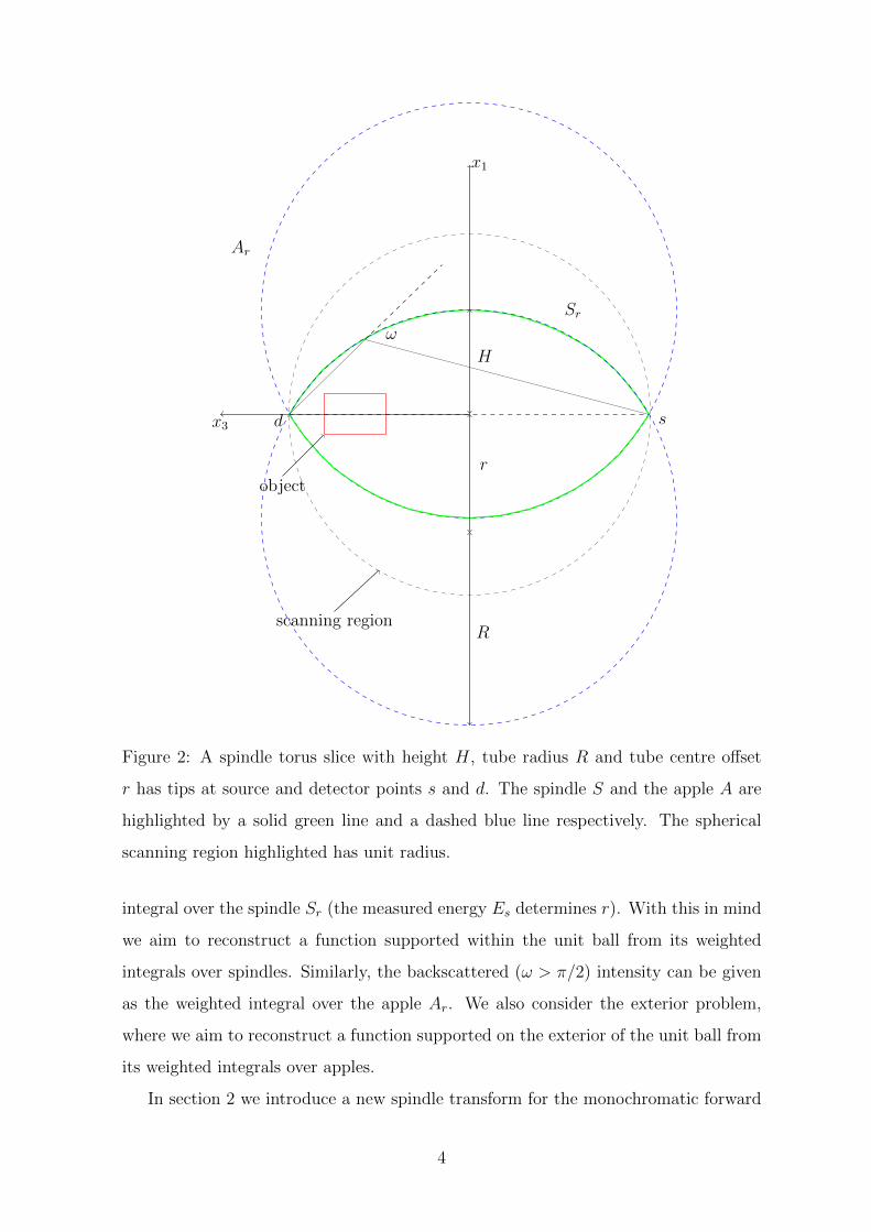
Figure 2: A spindle torus slice with height H, tube radius R and tube centre offset
r has tips at source and detector points s and d. The spindle S and the apple A are
highlighted by a solid green line and a dashed blue line respectively. The spherical
scanning region highlighted has unit radius.
integral over the spindle Sr (the measured energy Es determines r). With this in mind
we aim to reconstruct a function supported within the unit ball from its weighted
integrals over spindles. Similarly, the backscattered (ω > π/2) intensity can be given
as the weighted integral over the apple Ar. We also consider the exterior problem,
where we aim to reconstruct a function supported on the exterior of the unit ball from
its weighted integrals over apples.
In section 2 we introduce a new spindle transform for the monochromatic forward
4

scatter problem and introduce a generalization of the spindle transform which gives the
integrals of a function over the surfaces of revolution of a particular class of symmetric
curves. We prove the injectivity of the generalized spindle transform on the domain
of smooth functions compactly supported on the intersection of a hollow ball with the
upper half space x3 > 0. We show that our problem can be decomposed as a set of one
dimensional inverse problems, which we then solve to provide an explicit expression
for the harmonic coefficients of f . In section 2.1 we introduce a new toric interior
transform for the polychromatic forward scatter problem and prove its injectivity on
the domain of smooth functions compactly supported on the intersection of a hollow
ball and x3 > 0. A new apple and apple interior transform are also introduced in
section 2.2 for the monochromatic and polychromatic backscatter problem. Their
injectivity is proven on the domain of smooth functions compactly supported on the
intersection of the exterior of the unit ball and x3 > 0.
In section 3 we discuss possible approaches to the physical modelling of our problem
for the case of a monochromatic and polychromatic photon source, and explain how
this relates to the theory presented in section 2.
In section 4 we provide simulated density reconstructions of a test phantom via
a discrete approach. We simulate data sets using the equations given in section 2
and apply our reconstruction method with varying levels of added pseudo random
noise. We also simulate the added effects due to the attenuation of the incoming and
scattered rays in our data and see how this systematic error effects the quality of our
reconstruction.
2 A spindle transform
We will now parameterize the set of points on a spindle Sr in terms of spherical
coordinates (ρ, θ, ϕ) and give some preliminary definitions before going on to define
our spindle transform later in this section.
Consider the circular arc C as illustrated in figure 3. By the cosine rule, we have:
R2 = ρ2 + r2 + 2rρ sinϕ (3)
and hence:
ρ =
√r2 sin2 ϕ+ 1− r sinϕ. (4)
5

d s
ω
x1
x3
ϕ
C
object
scanning region
r
R
ρ
Figure 3: A circular arc C connecting source and detector points s and d. The circular
scanning region highlighted has unit radius.
Let Bε1,ε2 = x ∈ R3 : ε1 < |x| < ε2 denote the set of points on a hollow ball
with inner radius ε1 and outer radius ε2, and let S2 denote the unit sphere. Let
Z = R+ × S2. For a function f : R3 → R, let F : Z → R be iits polar form
F (ρ, θ, ϕ) = f(ρ sinϕ cos θ, ρ sinϕ sin θ, ρ cosϕ). We parameterize h ∈ SO(3) in terms
of Euler angles α and β, h = U(α)V (β), where U and V are rotations about the x3
and x2 axis respectively. We define an action of the rotation group SO(3) on the set
of real valued functions f on R3 in the natural way, and define an action on the polar
form as (h · F ) = (h · f).
The arc element for the circular arc C is given in [3] as:
dv = ρ
√1 + r2
1 + r2 sin2 ϕdϕ (5)
6
and the area element for the spindle Sr is:
dA = ρ sinϕ dvdθ. (6)
We define the spindle transform S : C∞0 (R3)→ C∞0 (Z) as:
Sf(r, α, β) =
∫ 2π
0
∫ π
0
ρ2 sinϕ
√1 + r2
1 + r2 sin2 ϕ(h · F ) (ρ, θ, ϕ) |
ρ=√r2 sin2 ϕ+1−r sinϕ
dϕdθ
(7)
where h = U(α)V (β).
This transform belongs to a larger class of integral transforms as we will now show.
Let p ∈ C1([0, π2]) be a curve parameterized by a colatitude ϕ ∈ [0, π
2]. Then we define
the class of symmetric curves ρ ∈ C1([0, 1]× [0, π]) by:
ρ(r, ϕ) = p(sin−1(r sinϕ)). (8)
From this we define the generalized spindle transform Sw,p : C∞0 (R3)→ C∞0 ([0, 1]×S2)
as:
Sw,pf(r, α, β) =
∫ 2π
0
∫ π
0
w(r, ϕ)ρ sinϕ
√ρ2 +
(dρ
dϕ
)2
(h · F ) (ρ, θ, ϕ) |ρ=ρ(r,ϕ) dϕdθ.
(9)
where the weighting w is dependant only on r and ϕ.
We now aim to prove injectivity of the generalized spindle transform Sw,p on the set
of smooth functions on a hollow ball. First we give some definitions and background
theory on spherical harmonics.
For integers l ≥ 0, |m| ≤ l, we define the spherical harmonics Y ml as:
Y ml (θ, ϕ) = (−1)m
√(2l + 1)(l −m)!
4π(l +m)!Pml (cosϕ)eimθ (10)
where,
Pml (x) = (−1)m(1− x2)m/2
dm
dxmPl(x) (11)
and
Pl(x) =1
2l
l∑k=0
(l
k
)2
(x− 1)l−k(x+ 1)k, (12)
are Legendre polynomials of degree l. The spherical harmonics Y ml form an orthonor-
mal basis for L2(S2), with the inner product:
〈f, g〉 =
∫S2
fgdτ =
∫ π
0
∫ 2π
0
f(θ, ϕ)g(θ, ϕ) sinϕ dθdϕ. (13)
7

So we have:∫S2
Y ml Y
m′
l′ dτ =
∫ π
0
∫ 2π
0
Y ml (θ, ϕ)Y m′
l′ (θ, ϕ) sinϕ dθdϕ = δll′δmm′ , (14)
where δ denotes the Kroneker delta.
From [9] we have the theorem:
Theorem 1. Let f ∈ C∞(R3) and let:
Flm =
∫S2
FY ml dτ, (15)
where dτ is the surface measure on the sphere. Then the series:
FN =∑
0≤l≤N
∑|m|≤l
FlmYml (16)
converges uniformly absolutely on compact subsets of Z to F .
We now show how the problem of reconstructing a density f from its integrals
Sw,pf for some curve p ∈ C1([0, π2]) can be broken down into a set of one dimensional
inverse problems to solve for the harmonic coefficients flm:
Lemma 1. Let f ∈ C∞0 (R3) and let p ∈ C1([0, π2]) be a curve, then:
Sw,pflm(r) = 2π
∫ π
0
w(r, ϕ)ρ sinϕ
√ρ2 +
(dρ
dϕ
)2
Flm(ρ)Pl(cosϕ) |ρ=ρ(r,ϕ) dϕ (17)
where,
Sw,pflm =
∫S2
(Sw,pf)Y ml dτ (18)
and Pl is a Legendre polynomial degree l.
Proof. Let τ ∈ S2 and let h ∈ SO(3) act on a spherical harmonic Y ml by (h ·Y m
l )(τ) =
Y ml (hτ). Then we have:
Sw,pf(r, α, β) =
∫ 2π
0
∫ π
0
w(r, ϕ)ρ sinϕ
√ρ2 +
(dρ
dϕ
)2
(h · F ) (ρ, θ, ϕ) |ρ=ρ(r,ϕ) dϕdθ
=∑l∈N
∑|m|≤l
∫ 2π
0
∫ π
0
w(r, ϕ)ρ sinϕ
√ρ2 +
(dρ
dϕ
)2
Flm(ρ)(h · Y ml )(θ, ϕ)dϕdθ
(19)
where h = U(α)V (β).
8
We may write h · Y ml as a linear combination of spherical harmonics of the same
degree [12, page 209]:
(h · Y ml )(τ) =
∑|n|<l
Y nl (τ)D(l)
n,m(h−1) (20)
where the block diagonal entries D(l)n,m are defined:
D(l)n,m(h) = D(l)
n,m(U(α)V (β)U(γ)) = e−inγd(l)n,m(cos β)e−imα (21)
and d(l)n,m is given, for m = 0, by:
d(l)n,0(cos β) = (−1)n
√(l − n)!
4π(l + n)!P nl (cos β). (22)
Here the Dl are the irreducible blocks which form the regular representation of SO(3).
After the expansion (20) is substituted into equation (19), we see that the inserted
sum is zero unless n = 0 and we have:
Sw,pf(r, α, β) = 2π∑l∈N
∑|m|≤l
√(2l + 1)
4πD
(l)0,m(h−1)
∫ π
0
w(r, ϕ)ρ sinϕ
√ρ2 +
(dρ
dϕ
)2
Flm(ρ)Pl(cosϕ)dϕ.
(23)
Since the regular representation of SO(3) is unitary, we have D(l)0,m(h−1) = D
(l)m,0(h) and
from the above we have:
Y ml (α, β) =
√(2l + 1)
4πD
(l)m,0(h). (24)
It follows that:
Sw,pf(r, α, β) = 2π∑l∈N
∑|m|≤l
Y ml (α, β)
∫ π
0
w(r, ϕ)ρ sinϕ
√ρ2 +
(dρ
dϕ
)2
Flm(ρ)Pl(cosϕ)dϕ.
(25)
From which we have:
Sw,pflm(r) =
∫S2
Sw,pfY ml dτ
= 2π
∫ π
0
w(r, ϕ)ρ sinϕ
√ρ2 +
(dρ
dϕ
)2
Flm(ρ)Pl(cosϕ) |ρ=ρ(r,ϕ) dϕ
(26)
and the result is proven.
9

We now go on to show that the set of one dimensional integral equations derived
above are uniquely solvable for flm for every l ∈ N, |m| ≤ l. Given the antisymmetry
of the Legendre polynomials for odd l, we see that Sw,pflm = 0 for odd l, for any
given f ∈ C∞0 (R3) and curve p ∈ C1([0, π2]). So for the moment we focus on the
reconstruction of the coefficients flm for even l.
We now have our main theorem:
Theorem 2. Let p ∈ C1([0, π2]) be such that p(ϕ) 6= 0 for all ϕ ∈ [0, π
2], and let g ∈
C1([0, 1)) be defined as g(x) = p(sin−1 x). Let A = ρ ∈ [0, 1) : g(ρ) ∈ [0, ε1] ∪ [ε2, ε3]
and let w : [0, 1] × [0, π] → R be a weighting such that W (r, ρ) = w(r, sin−1(ρ/r)
)and its first order partial derivative with respect to r is continuous on (r, ρ) : r ∈
A,min(A) ≤ ρ ≤ r and W (ρ, ρ) 6= 0 on A. Let f ∈ C∞0 (B0,ε1 ∪ Bε2,ε3), where
ε1 < p(0) < ε2. Then Sw,pf determines the harmonic coefficients Flm uniquely for
ρ ∈ g([0, 1)) for all l ∈ 2k : k ∈ N, |m| ≤ l.
Proof. Given the symmetry of the Legendre polynomials Pl for even l, we have:
1
4πSw,pflm(r) =
∫ π2
0
w(r, ϕ)ρ sinϕ
√ρ2 +
(dρ
dϕ
)2
Flm(ρ)Pl(cosϕ) |ρ=ρ(r,ϕ) dϕ
=
∫ π2
0
w(r, ϕ)g(ρ) sinϕ√g(ρ)2 + r2 cos2 ϕg′(ρ)2Flm(g(ρ))Pl(cosϕ) |ρ=r sinϕ dϕ.
(27)
After making the substitution ρ = r sinϕ , equation (27) becomes:
1
4πSw,pflm(r) =
∫ r
0
Flm(g(ρ))Kl(r, ρ)√r − ρ
dρ (28)
a Volterra integral equation of the first kind with weakly singular kernel, where:
Kl(r, ρ) = W (r, ρ)ρg(ρ)
√g(ρ)2 + (r2 − ρ2)g′(ρ)2
r√r + ρ
Pl
(√1− ρ2
r2
). (29)
As Flm g is zero for ρ close to 0, given our prior assumptions regarding W and given
that g ∈ C1([0, 1)), we can see that Kl and its first order derivative with respect to r
is continuous on the support of Flm g.
Multiplying both sides of equation (28) by 1/√z − r and integrating with respect
to r over the interval [0, z], yields:
1
4π
∫ z
0
Sw,pflm(r)√z − r
dr =
∫ z
0
Flm(g(ρ))
[∫ z
ρ
Kl(r, ρ)√z − r
√r − ρ
dr
]dρ (30)
10

after changing the integration order. Making the substitution r = ρ+ (z − ρ)t, gives:
Ql(z, ρ) =
∫ z
ρ
Kl(r, ρ)√z − r
√r − ρ
dr
=
∫ 1
0
Kl(ρ+ (z − ρ)t, ρ)√t√
1− tdt
(31)
from which we have:
Ql(z, z) = πKl(z, z) = W (z, z)πclg(z)2
√2z
(32)
where,
cl = Pl(0) =(−1)(l/2)
2l
(l
l/2
). (33)
So by our assumptions that p is non zero and W is non zero on the diagonal, Ql(z, z) 6=
0 on the support of Flm g.
Differentiating both sides of equation (30) with respect to z and rearranging gives:
vlm(z) =
∫ z
0
Flm(g(ρ))Hl(z, ρ)dρ+ Flm(g(z)) (34)
which is a Volterra type integral equation of the second kind, where:
vlm(z) =1
4π2Kl(z, z)
d
dz
∫ z
0
Sw,pflm(r)√z − r
dr (35)
and,
Hl(z, ρ) =1
πKl(z, z)
d
dzQl(z, ρ). (36)
Given the continuity of Hl on the support of Flm g and the continuity of Flm g on
[0, 1], the Neumann series associated with equation (34) converges and we may write
our solution:
Flm(g(z)) =
∫ z
0
Rl(z, ρ)vlm(ρ)dρ+ vlm(z) (37)
where the resolvent kernel,
Rl(z, ρ) =∞∑i=1
Hl,i(z, ρ) (38)
is defined by,
Hl,1(z, ρ) = Hl(z, ρ), Hl,i(z, ρ) =
∫ z
ρ
Hl(z, x)Hl,i−1(x, ρ)dx ∀i ≥ 2. (39)
Since the series converges, the solution is unique and we may reconstruct Flm explicitly
for ρ ∈ g([0, 1)).
11
Here as we can only reconstruct the coefficients Flm for even l, for a general f ∈
C∞0 (R3) and curve p ∈ C1([0, π2]), the spindle data Sw,pf is insufficient to recover f
uniquely for |x| ∈ p([0, π2)). However if we consider those functions f ∈ C∞0 (R3) whose
support lies in the upper half space x3 > 0 we find that uniqueness is possible, as the
following theorem shows:
Theorem 3. Let U = (x1, x2, x3) ∈ R3 : x3 > 0 and let f ∈ C∞0 (U). Then the even
coefficients Flm for l ∈ 2k : k ∈ N = Ne, |m| ≤ l determine F uniquely and:
F (ρ, θ, ϕ) = 2∑l∈Ne
∑|m|≤l
Flm(ρ)Y ml (θ, ϕ) (40)
for ρ ≥ 0, 0 ≤ θ ≤ 2π and 0 ≤ ϕ ≤ π2.
Proof. We can write F as the sum of its even and odd coefficients:
F (ρ, θ, ϕ) = Fo(ρ, θ, ϕ)+Fe(ρ, θ, ϕ) =∑
odd l∈N
∑|m|≤l
Flm(ρ)Y ml (θ, ϕ)+
∑even l∈N
∑|m|≤l
Flm(ρ)Y ml (θ, ϕ).
(41)
Then from our assumption, we have:
−Fe(ρ, θ, ϕ) = Fo(ρ, θ, ϕ) =∑
odd l∈N
∑|m|≤l
Flm(ρ)Y ml (θ, ϕ)
=∑m∈Z
∑odd l≥|m|
c(l,m)Flm(ρ)Pml (cosϕ)
eimθ=∑m∈Z
Fmo (ρ, ϕ)eimθ
(42)
for all ρ ≥ 0, 0 ≤ θ ≤ 2π and π2≤ ϕ ≤ π, where:
c(l,m) = (−1)m
√(2l + 1)(l −m)!
4π(l +m)!. (43)
We have:
−Fme (ρ, ϕ) = − 1
2π
∫ 2π
0
Fe(ρ, θ, ϕ)e−imθdθ = Fmo (ρ, ϕ) for ρ ≥ 0,
π
2≤ ϕ ≤ π. (44)
The associated Legendre polynomials Pml are symmetric when l + m is even and
antisymmetric otherwise. It follows that:
Fo(ρ, θ, ϕ) =∑m∈Z
(−1)m+1Fmo (ρ, π − ϕ)eimθ
=∑m∈Z
(−1)mFme (ρ, π − ϕ)eimθ
=∑m∈Z
Fme (ρ, ϕ)eimθ
(45)
12

for ρ ≥ 0, 0 ≤ θ ≤ 2π and 0 ≤ ϕ ≤ π2. The result follows.
Corollary 1. Let f ∈ C∞0 (Bε1,ε2 ∩ U) for some 0 < ε1 < ε2 < 1. Let ε1 ≤ ε ≤ ε2
and let δ = 1−ε22ε
. Then Sf known for 0 ≤ r ≤ δ and for all (α, β) ∈ S2 determines f
uniquely for ε ≤ |x| ≤ 1.
Proof. Let p(ϕ) =√
1 + δ2 sin2 ϕ − δ sinϕ and let w ≡ 1. Then Sf(δr, α, β) =
Sw,pf(r, α, β) for r ∈ [0, 1], (α, β) ∈ S2. The result follows from Theorems 2 and
3.
2.1 A toric interior transform
In the previous section we considered the three dimensional Compton scatter tomog-
raphy problem for a monochromatic source and energy sensitive detector pair. The
polychromatic source case is covered here and we consider the modifications needed
in our model to describe a full spectrum of initial photon energies.
In an X-ray tube electrons are accelerated by a large voltage (EmkeV) towards a
target material and photons are emitted. Due to conservation of energy, the emitted
photons have energy no greater than EmkeV. So for a given measured energy Es, where
Em1+2Em/E0
< Es < Em, the set of scatterers is the union of spindle tori corresponding
to scattering angles ω in the range 0 < ω < cos−1(
1− E0(Em−Es)EsEm
)(corresponding to
energies E in the range Es < E < Em). That is, the set of scatterers is a torus interior:
Ir =
(x1, x2, x3) ∈ R3 :
(r −
√x2
1 + x22
)2
+ x23 < 1 + r2
(46)
where r is determined by the scattered energy measured Es. See [1] for an explanation
of the two dimensional case.
With this in mind we define the spindle interior transform I : C∞0 (R3) → C∞0 (Z)
as:
If(r, α, β) =
∫ 2π
0
∫ π
0
∫ √r2 sin2 ϕ+1−r sinϕ
0
ρ2 sinϕ(h · F )(ρ, θ, ϕ)dρdϕdθ. (47)
and we have the uniqueness theorem for a weighted spindle interior transform:
13

Theorem 4. Let f ∈ C∞0 (Bε1,ε2 ∩ U) for some 0 < ε1 < ε2 < 1 and and let δ2 =1−ε222ε2
and δ1 =1−ε212ε1
. Let f be defined as:
1√(1−|x|2)2
4|x|4 + 1f(x) =
1− |x|2
2|x|2−
(1−|x|2)2
4|x|4√(1−|x|2)2
4|x|4 + 1
f (x) . (48)
Define the weighted interior transform:
Iwf(r′, α, β) =
∫ r′
0
∫ 2π
0
∫ π
0
w(r′, t, ϕ)ρ2 sinϕ
t√
sin2 ϕt2
+ 1(h · F ) (ρ, θ, ϕ) |
ρ=√
sin2 ϕ
t2+1− sinϕ
t
dϕdθdt,
(49)
where h = U(α)V (β) and r′ = 1/r. Let us suppose that the weighting w satisfies the
following:
1. w can be decomposed as w(r′, t, ϕ) = w1(r′, t)w2(t, ϕ).
2. W2(t, ρ) = w2
(1/t, sin−1(ρ/t)
)and its first order partial derivative with respect
to t is continuous on the triangle T = (t, ρ) ∈ R2 : ε1 ≤ t ≤ ε2, ε1 ≤ ρ ≤ t and
W2(ρ, ρ) 6= 0 on [ε1, ε2].
3. w1(r′, t) and its first order partial derivatives are bounded on 0 ≤ r′ < ∞ and
w1(r′, r′) 6= 0 for 0 ≤ r′ <∞.
Then Iwf known for all r′ ∈ [0,∞) and for all (α, β) ∈ S2 determines f uniquely for
0 < |x| < 1.
Proof. We have:
Iwf(r′, α, β) =
∫ r′
0
w1(r′, t)G(t, α, β)dt, (50)
where,
G(t, α, β) =
∫ 2π
0
∫ π
0
w2(t, ϕ)ρ2 sinϕ
t√
sin2 ϕt2
+ 1(h · F ) (ρ, θ, ϕ) |
ρ=√
sin2 ϕ
t2+1− sinϕ
t
dϕdθ. (51)
Differentiating both sides of equation (50) with respect to r′ and rearranging yields:
g(r′, α, β) =
∫ r′
0
L(r′, t)G(t, α, β)dt+G(r′, α, β) (52)
where,
g(r′, α, β) = −d
dr′Iwf(r′, α, β)
w1(r′, r′)(53)
14

and,
L(r′, t) =d
dr′w1(r′, t)
w1(r′, r′). (54)
Given our prior assumptions regarding w1, we can solve the Volterra equation of the
second kind (52) uniquely for Glm(t) for 0 < t <∞. From which we have:
G
(1
δ1t, α, β
)=
∫ 2π
0
∫ π
0
w2
(1
δ1t, ϕ
)δ1tρ
2 sinϕ√δ2
1t2 sin2 ϕ+ 1
(h · F ) (ρ, θ, ϕ) |ρ=√δ22t
2 sin2 ϕ+1−δ2t sinϕdϕdθ
=δ1t√
1 + δ21t
2Sw3,pf(t, α, β)
(55)
for t ∈ (0, 1], where w3(t, ϕ) = w2
(1δ1t, ϕ)
and p(ϕ) =√
1 + δ21 sin2 ϕ − δ1 sinϕ. By
our assumptions regarding w2, the weighting w3 satisfies the conditions of Theorem 2,
as does the curve p. The result follows from Theorem 2.
Corollary 2. Let f ∈ C∞0 (Bε1,ε2 ∩ U) for some 0 < ε1 < ε2 < 1. Then If as defined
in equation (47) known for all r ∈ [0,∞) and for all (α, β) ∈ S2 determines f uniquely
for 0 < |x| < 1.
Proof. Let f be defined as in Theorem 4. Then, after making the substitution ρ =√sin2 ϕt2
+ 1− sinϕt
in equation (47), we have:
If(r, α, β) =
∫ 1r
0
∫ 2π
0
∫ π
0
ρ2 sinϕ
t√
sin2 ϕt2
+ 1(h · F ) (ρ, θ, ϕ) |
ρ=√
sin2 ϕ
t2+1− sinϕ
t
dϕdθdt
= Iwf(1/r, α, β)
(56)
for all r ∈ (0,∞) and for all (α, β) ∈ S2, where the weighting w ≡ 1. The result
follows from Theorem 4.
The advantage of using a polychromatic source (e.g. an X-ray tube) over a monochro-
matic source, which would most commonly be some type of gamma ray source, is that
they have a significantly higher output intensity and so the data acquisition is faster.
They are also safer to handle and use and are already in use in many fields of imag-
ing. The downside, when compared to using a monochromatic source, would be a
decrease in efficiency of our reconstruction algorithm and the added differentiation
step required in the inversion process. This makes the polychromatic problem more ill
posed, and so small errors in our measurements would be more greatly amplified in the
15
reconstruction. We should consider both source types for further testing to determine
an optimal imaging technique.
2.2 The exterior problem
Here we consider the exterior problem, and show that a full set of apple integrals
(which represent the backscattered intensity) are sufficient to reconstruct a compactly
supported density on the exterior of the unit ball.
2.2.1 An apple transform
For backscattered photons (for scattering angles ω > π/2) the surface of scatterers is
an apple Ar. Refer back to figure 2. The spherical coordinates (ρ, θ, ϕ) of the points
on Ar can be parameterized as follows:
ρ =
√r2 sin2 ϕ+ 1 + r sinϕ, 0 ≤ θ ≤ 2π, 0 ≤ ϕ ≤ π. (57)
We define the apple transform A : C∞0 (R3)→ C∞0 (Z) as:
Af(r, α, β) =
∫ 2π
0
∫ π
0
ρ2 sinϕ
√1 + r2
1 + r2 sin2 ϕ(h · F )(ρ, θ, ϕ) |
ρ=√r2 sin2 ϕ+1+r sinϕ
dϕdθ,
(58)
where h = U(α)V (β). We have the uniqueness theorem for the apple transform for
functions supported on the exterior of the unit ball:
Theorem 5. Let f ∈ C∞0 (Bε1,ε2 ∩ U) for some 1 < ε1 < ε2 < ∞. Let ε1 ≤ ε ≤ ε2
and let δ = ε2−12ε
. Then Af known for 0 ≤ r ≤ δ and for all (α, β) ∈ S2 determines f
uniquely for 1 ≤ |x| ≤ ε.
Proof. Let p(ϕ) =√
1 + δ2 sin2 ϕ + δ sinϕ and let w ≡ 1. Then Af(δr, α, β) =
Sw,pf(r, α, β) for r ∈ [0, 1], (α, β) ∈ S2. The result follows from Theorems 2 and
3.
2.2.2 An apple interior transform
Similar to our discussion at the start of section 2.1, if the source is polychromatic the
set of backscatterers is an apple interior. Hence we define the apple interior transform
16

AI : C∞0 (R3)→ C∞0 (Z):
AIf(r, α, β) =
∫ 2π
0
∫ π
0
∫ √r2 sin2 ϕ+1+r sinϕ
1
ρ2 sinϕ(h · F )(ρ, θ, ϕ)dρdϕdθ. (59)
and we have a theorem for its injectivity:
Theorem 6. Let f ∈ C∞0 (Bε1,ε2 ∩ U) for some 1 < ε1 < ε2 <∞. Let ε1 ≤ ε ≤ ε2 and
let δ = ε2−12ε
. Then AIf known for 0 ≤ r ≤ δ and for all (α, β) ∈ S2 determines f
uniquely for 1 ≤ |x| ≤ ε.
Proof. Let f be defined as:
1√(|x|2−1)2
4|x|4 + 1f(x) =
(|x|2−1)2
4|x|4√(|x|2−1)2
4|x|4 + 1+|x|2 − 1
2|x|2
f (x) . (60)
Then by Leibniz rule we have:
rd
drAIf(r, α, β) =
∫ 2π
0
∫ π
0
ρ2 sinϕ√1 + r2 sin2 ϕ
(h · F )(ρ, θ, ϕ) |ρ=√r2 sin2 ϕ+1+r sinϕ
dϕdθ
=1√
1 + r2Af(r, α, β)
(61)
So AIf known for 0 ≤ r ≤ δ and for (α, β) ∈ S2 determines Af on the same set after
differentiating. The result follows from Theorem 5.
3 A physical model
Here we explain how the theory presented in the previous section relates to what we
measure in a practical setting.
We consider an intensity of photons scattering from a point x as illustrated in figure
4. The points s and d are the centre points of the source and detector respectively.
The intensity of photons scattered from x to d with energy Es is:
I (Es) = I0 (Eλ) e−
∫Lsx
µ(Eλ,Z)f (x) dV × dσ
dΩ(Es, ω) e
−∫Lxd
µ(Es,Z)S (q, Z) dΩ. (62)
where Z denotes the atomic number, ω the scattering angle and Lsx and Lxd are the
line segments connecting s to x and x to d respectively. f(x) denotes the electron
17

d sϕ
EλEs
xC
rR
ρ
Figure 4: A scattering event occurs on the circular arc C with initial photon energy
Eλ from the source s to the detector d with energy Es.
density (number of electrons per unit volume) at the scattering point x and dV is the
volume measure. f is the quantity to be reconstructed.
Let Wk(Eλ) denote the incident photon flux (number of photons per unit area per
unit time), energy Eλ, measured at a fixed distance D from the source. Then the
incident photon intensity I0 can be written:
I0(Eλ) =tD2Wk(Eλ)
(ρ cosϕ+ 1)2 + ρ2 sin2 ϕ, (63)
where t is the emission time.
The Klein-Nishina differential cross section dσ/dΩ, is defined by:
dσ
dΩ(Es, ω) =
r20
2
(EsEλ
)2(EsEλ
+EλEs− 1 + cos2 ω
), (64)
where r0 is the classical electron radius and cosω = r/√
1 + r2. This predicts the
scattering distribution for a photon off a free electron at rest. Given that the atomic
electrons typically are neither free nor at rest, a correction factor is included, namely
the incoherent scattering function S (q, Z). Here q = Eλhc
sin (ω/2) is the momentum
transferred by a photon with initial energy:
Eλ =Es
1− (Es/E0) (1− cosω)(65)
scattering at an angle ω, where h is Planck’s constant and c is the speed of light. As
the scattering function S is dependant on the atomic number Z, we set Z = Zavg to
some average atomic number as an approximation and interpolate values of S(q, Zavg)
from the tables given in [10].
18

The solid angle subtended by x and d may be approximated as:
dΩ =A
4π× 1− ρ cosϕ
(1− ρ cosϕ)2 + ρ2 sin2 ϕ, (66)
where A is the detector area.
The exponential terms in equation (62) account for the attenuation of the incoming
and scattered rays. We approximate:
e−∫Lsx
µ(Eλ,Z)e−
∫Lxd
µ(Es,Z) ≈ 1 (67)
In general this approximation is unrealistic. For example in medical CT, if we were
scanning a relatively large (e.g. the size of someone’s head) mass of organic material at
a low energy (e.g. 50keV), the absorption would play a significant role and the above
model would over approximate the data. However in an application where the objects
are smaller (centimetres in diameter) and where we can scan at a higher energy (≈
1MeV), the effects due to absorption would be less prevalent and Compton scattering
would be the dominant interaction. For example, in airport baggage screening typical
hand luggage would be a small bag containing a few low effective Z densities (e.g.
nail varnish (Acetone), water, some plastic (polyethylene) etc.) and the rest may be
clothes or air. Here also, as we are not worried about dosage, we can scan at high
energies (e.g. using a high voltage X-ray tube or high emission energy gamma ray
source). We will simulate the error due to attenuation later, in section 4, and show
the effects of neglecting the attenuation in our reconstruction.
3.0.1 The monochromatic case
Let our density f be supported on Bε1,ε2 ∩ U for some 0 < ε1 < ε2 < 1 and let
δ2 =1−ε222ε2
. If the source s is monochromatic (Eλ remains fixed), then the forward
Compton scattered intensity measured is:
I(r, α, β) = ctD2Wk(Eλ)dσcdΩ
(r)Sw,pf(r, α, β), (68)
where p ∈ C1([0, π]) is defined by p(ϕ) =√
1 + δ22 sin2 ϕ − δ2 sinϕ, c is a constant
thickness and:dσcdΩ
(r) =dσ
dΩ(Es, ω)S(q, Zavg) (69)
19

depends only on r. Here the variable r ∈ [0, 1] determines the scattered energy Es and
(α, β) ∈ S2 determines the source and detector position. The weighting w is given by:
w(r, ϕ) =A(1− ρ cosϕ)
4π[(1− ρ cosϕ)2 + ρ2 sin2 ϕ
] [(ρ cosϕ+ 1)2 + ρ2 sin2 ϕ
] . (70)
where ρ =√
1 + r2 sin2 ϕ− r sinϕ. It is left to the reader to show that the weighting
w satisfies the conditions given in Theorem 2. After dividing through by the physical
modelling terms in equation (68), we can invert the weighted spindle transform Sw,pf
as in Theorem 2 to obtain an analytic expression for f in terms of the Compton
scattered intensity I.
3.0.2 The polychromatic case
Here we have a spectrum of incoming photon energies. See figure 5. The Compton
Figure 5: A polychromatic Tungsten target spectrum with an X-ray tube voltage of
V = 200keV and a 1mm Copper filter. Spectrum calculated using SpekCalc [16].
scattered intensity measured for a tube centre offset r = 1/r′ for a source and detector
position (α, β) ∈ S2 may be written:
I(r′, α, β) = stD2Iwf(r′, α, β), (71)
20

with the weighting:
w(r′, t, ϕ) =
[Wk(r
′, t)dσcdΩ
(r′, t)
]w2(t, ϕ) = w1(r′, t)w2(t, ϕ), (72)
where w2 = w as in equation (70). Here the scattering probabilty dσcdΩ
and the photon
flux Wk are dependant on r′ and the integration variable t as in subsection 2.1. While
the weighting w is separable as in Theorem 4, the incident photon flux Wk(r′, r′) =
Wk(Em) = 0 for all r′, where Em is the maximum spectrum energy. Hence w1(r′, r′) ≡ 0
and w fails to meet the conditions of Theorem 4. To deal with this, let:
wavg(r′) =1
r′
∫ r′
0
w1(r′, t)dt (73)
and let wapp(r′, t, ϕ) = wavg(r′)w2(t, ϕ). Then, although we sacrifice some accuracy
in our forward model, wapp would satisfy the conditions given in Theorem 4 and we
can obtain an analytic expression for the density. The error in our approximation is
bounded by:
|wavg(r′)− w1(r′, t)| ≤∣∣∣∣maxt∈[0,r′]
w1(r′, t)− mint∈[0,r′]
w1(r′, t)
∣∣∣∣ (74)
for all r′ ≥ 0, 0 ≤ t ≤ r′. So provided the changes in the incident photon energy Es
(Es is determined by t) are negligible over the range t ∈ [0, r′], the error in wapp would
be small.
4 Simulations
Here we provide reconstructions of a test phantom density at a low resolution using
simulated datasets of the unweighted spindle and spindle interior transforms, and sim-
ulate noise as additive psuedo Gaussian noise. To simulate data for each transform we
discretize the integrals in equations (7) and (47), and solve the least squares problem:
arg minx‖Ax− b‖2 + λ2‖x‖2 (75)
for some regularisation parameter λ > 0, where A is the discrete forward operator of
the transform considered, x is the vector of density pixel values and b = Ax is the
simulated transform data. We simulate perturbed data bε via:
bε = b+ εG‖b‖√n
(76)
21

where G is a pseudo random vector of samples from the standard Gaussian distibution
and n is the number of entries in b. The proposed noise model has the property that
‖b− bε‖/‖b‖ ≈ ε, so a noise level of ε is ε× 100% relative error.
We consider the test phantom displayed in figure 6. The unit cube is discretised into
50×50×50 pixels and a hollow ball, some stairs and a low density block with a metal
sheet passing through it are placed in upper unit hemisphere. Slice profiles are given
in the right hand figure to display the metal sheet and the hollow shell. We sample
25 r values (corresponding to spindles with heights H ∈ 0.02 + 0.04i : 0 ≤ i < 25),
45 α values α ∈ 2πi45
: 0 ≤ i < 45 and 45 β values β ∈ π90
(1 + i) : 0 ≤ i < 45.
So we have an underdetermined sparse system matrix A with 50625 rows and 125000
columns. To reconstruct we solve the regularised problem (75) using the conjugate
gradient least squares algorithm (CGLS) and pick our regularisation parameter λ via
a manual approach. In each reconstruction presented, any negative values are set to
zero and the iteration number and noise level are given in the figure caption.
In figure 7 we have presented a reconstruction of the test phantom in the absence
of added noise. Given the symmetries involved in our geometry, the density has been
rotated and reflected in the xy plane in the reconstruction. To better visualise the
reconstruction we set our reconstructed images to 0 in the lower half space. In figure
8 we display the same zero noise reconstruction but with the voxel values set to zero
in the lower hemisphere.
Figures 8–13 show test phantom reconstructions from spindle and spindle interior
transform data with varying levels of added noise. In the absence of noise (figures 8
and 11) the reconstructions are ideal. However in the presence of noise we notice a
harsher degradation in image quality when reconstructing with spindle interior data.
This is because the spindle interior problem is inherently more ill posed due to the
extra differentiation step required in the inversion process. At a low noise level (figure
12), while the shape of the objects can be deciphered and the ball appears to be hollow,
the reconstructions are not clear, in particular the lower density block and the metal
sheet start to become lost in the reconstruction. At a higher noise level (figure 13), the
artefacts in the reconstruction are severe, the ball no longer appears to be hollow and
the metal sheet fails to reconstruct. So, although the practical advantages of using a
polychromatic source such as an X-ray tube or linear accelerator are clear (i.e. reduced
22

data acquisition time, easy and safe to use etc.), a low noise level would need to be
maintained to achieve a satisfactory image quality. The spindle transform inversion
performs better when there is added noise. At a low noise level (figure 9), the size and
shape of the objects is clear and the image contrast is good. At a higher noise level,
the background noise in the image is amplified and the ends of metal sheet are hard
to identify. We notice, in the presence of noise, that the thinner object (namely the
metal sheet) is hardest to reconstruct. This is as we’d expect since smaller densities
are determined by the higher frequency harmonic components which degrade faster
with noise.
To simulate data for the reconstructions presented in figures 6–13 we applied the
discrete operator A to the vector of test phantom pixels x and added Gaussian noise.
We now include the effects due the attenuation of the incoming and scattered rays in
our simulated data and see how this effects the quality of our reconstruction. For our
first example, we set the size of the scanning cube to be 20× 20× 20cm3 (each pixel
is 4 × 4 × 4mm3) and the phantom materials are polyethylene (low density block),
water (the stairs), rubber (the ball) and Aluminium (the metal sheet). We model the
source as Co60, a monochromatic gamma ray source widely used in security screening
applications (e.g. screening of freight shipping containers), which has an emission
energy of 2824keV. We also add 1% Gaussian noise as in equation (76) to simulate
random error as well as the systematic error due to attenuation effects. Our results
are presented in figure 14. Here the phantom reconstruction is satisfactory with only
minor artefacts appearing in the image. So if we scan a low effective Z target of a
small enough size with a high energy source, the effects due to attenuation can be
neglected while maintaining a satisfactory image quality. For our next example, we
set the scanning cube size to be 50× 50× 50cm3 (each pixel is 1× 1× 1cm3) and the
phantom materials are Teflon (low density block), PVC (stairs), polyoxymethylene
(ball) and steel (the metal sheet). The source is Co60 as in our last example and again
we add a further 1% Gaussian noise to the simulated data after we have accounted
for the attenuative effects. Our results are presented in figure 15. Here, with a larger,
higher density target, the effects due to attenuation are significant and the artefacts
in the reconstruction are more severe.
23

Figure 6: Test phantom.
Figure 7: Test phantom reconstruction from spindle transform data no noise, 2000
iterations.
24
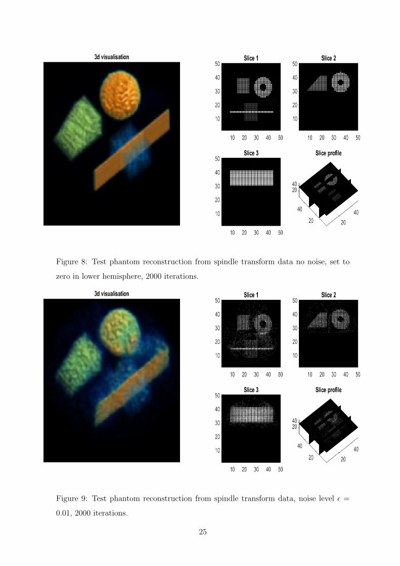
Figure 8: Test phantom reconstruction from spindle transform data no noise, set to
zero in lower hemisphere, 2000 iterations.
Figure 9: Test phantom reconstruction from spindle transform data, noise level ε =
0.01, 2000 iterations.
25

Figure 10: Test phantom reconstruction from spindle transform data, noise level ε =
0.05, 2000 iterations.
Figure 11: Test phantom reconstruction from spindle interior data no noise, 2000
iterations.
26

Figure 12: Test phantom reconstruction from spindle interior data, noise level ε = 0.01,
2000 iterations.
Figure 13: Test phantom reconstruction from spindle interior data, noise level ε = 0.05,
2000 iterations.
27

Figure 14: Small, low effective Z test phantom reconstruction from spindle transform
data with attenuation effects added and noise level ε = 0.01, 2000 iterations.
Figure 15: Large, high effective Z test phantom reconstruction from spindle transform
data with attenuation effects added and noise level ε = 0.01, 2000 iterations.
28
5 Conclusions and further work
We have presented a new acquisition geometry for three dimensional density recon-
struction in Compton imaging with a monochromatic source and introduced a new
spindle transform and a generalization of the spindle transform for the surfaces of
revolution of a class of symmetric C1 curves. The generalized spindle transform was
shown to be injective on the domain of smooth functions f supported on a the inter-
section of a hollow ball with the upper half space x3 > 0. In section 2 it was shown
that our problem could be decomposed into a set of one dimensional inverse problems
to solve for the harmonic coefficients of a given density, which we then went on to solve
via the explicit inversion of a class of Volterra integral operators. Later in section 2.1
we considered the problem for a polychromatic source and introduced a new spindle
interior transform and proved its injectivity on the set of smooth functions compactly
supported on the intersection of a hollow ball and x3 > 0. We also considered the
exterior problem for backscattered photons with a monochromatic and polychromatic
photon source, where in section 2.2 we introduced a new apple and apple interior
transform. Their injectivity was proven on the set of smooth functions compactly
supported on the intersection of the exterior of the unit ball and x3 > 0. We note that
in Palamodov’s paper on generalized Funk transforms [14], although he provides an
explicit inverse for a fairly general family of integral transforms over surfaces in three
dimensional space, the spindle transform is excluded from this family of transforms.
In section 3 we discussed a possible approach to the physical modelling of our for-
ward problem for both a monochromatic and polychromatic source. In the monochro-
matic source case, we found that the Compton scattered intensity resembled a weighted
spindle transform (as in Theorem 2) which could be solved explicitly via repeated ap-
proximations. In the polychromatic source case, with a more accurate forward model,
we found that an analytic reconstruction was not possible. So we suggested a simpli-
fied model in order to obtain an analytic expression for the density, and gave some
simple error estimates for our approximation.
Test phantom reconstructions were presented in section 4 using simulated datasets
from spindle and spindle interior transform data with varying levels of added pseudo
random Gaussian noise. When reconstructing with spindle transform data the recon-
29

structions were satifactory for noise levels up to 5%. We saw a harsher reduction in
image quality in the presence of added noise when reconstructing from spindle inte-
rior data. This was as expected given the increased instability of the spindle interior
problem.
In the latter part of section 4, we provided further reconstructions of our test
phantom image in the presence of a systematic error due to the attenuative effects
of the incoming and scattered rays. We found, when scanning a small low effective
Z target with a high energy source, that the attenuative effects could be neglected
while maintaining a good image quality. We also gave an example where the target
materials were larger and higher effective Z. Here the effects due to attenuation were
significant and we saw a more severe reduction in the image quality.
As the stability of the spindle transform has not yet been addressed, in future work
we aim to analyse the spindle transform from a microlocal perspective to investigate
whether this can shed some light on its stability. Although the injectivity of the
exterior problem is covered here, simulations of an exterior density reconstruction are
left for future work.
Acknowledgements
The authors would like to thank Rapiscan and the EPSRC for the CASE award funding
this project, and WL would also like to thank the Royal Society for the Wolfson
Research Merit Award that also contributed to this project.
References
[1] Webber, J., “X-ray Compton scattering tomography” Inverse problems in science
and engineering, Vol. 24, Issue. 8, 2016
[2] Palamodov, V. P., “An analytic reconstruction for the Compton scattering to-
mography in a plane” Inverse Problems 27 125004 (8pp), 2011.
[3] Nguyen, M., and Truong T., “Inversion of a new circular-arc Radon transform for
Compton scattering tomography” Inverse Problems 26 065005, 2010.
30

[4] Norton, S. J., “Compton scattering tomography” J. Appl. Phys. 76 200715, 1994.
[5] V. Maxim, M. Frandes, R. Prost, “Analytical inversion of the Compton transform
using the full set of available projections” Inverse Problems 25 095001, 2009.
[6] Nguyen, M. K., Truong, T. T., and Grangeat, P., “Radon transforms on a class
of cones with fixed axis direction” J. Phys. A: Math. Gen. 38 80038015, 2005.
[7] Truong, T. T., Nguyen, M. K. and Zaidi, H., “The mathematical foundations
of 3D Compton scatter emission imaging” International Journal of Biomedical
Imaging, Article ID 92780, Volume 2007.
[8] Truong, T. T. and Nguyen, M. K. “Recent developments on Compton scatter
tomography: theory and numerical simulations” Numerical Simulation - From
Theory to Industry, Chapter 6, 2012.
[9] Seeley, R. T., “Spherical Harmonics” The American Mathematical Monthly, Vol.
73, No. 4, Part 2: Papers in Analysis, pp. 115-121, 1966.
[10] Hubbell, J. H. et. al, “Atomic form factors, incoherent scattering functions and
photon scattering cross sections” J. Phys. Chem. Ref. Data, Vol. 4, No. 3, 1975.
[11] Natterer, F., “The mathematics of computerized tomography” SIAM, 2001.
[12] Driscoll, J. R., Healy, D. M., “Computing Fourier transforms and convolutions
on the 2-sphere” Advances in applied mathematics 15, 202–250, 1994.
[13] Adams, R. A., “Sobolev spaces” Academic press, 1975.
[14] Palamodov, V. P., “A uniform reconstruction formula in integral geometry” In-
verse Problems 28 065014, 2012.
[15] Weiss, R., “Product integration for the generalized Abel equation” Mathematics
of computation, volume 26, number 117, 1972.
[16] Poludniowski G., Landry G., DeBlois F., Evans P. M. and Verhaegen F.
“SpekCalc: a program to calculate photon spectra from tungsten anode x-ray
tubes” Phys. Med. Biol. 54 N433438, 2009.
31