three dimensional reconstruction ofcross sectional intracoronary
TRANSCRIPT
Br HeartJ7 (Supplement 2) 1995;73:26-32
Three dimensional reconstruction of cross
sectional intracoronary ultrasound: clinical or
research tool?
Carlo Di Mario, Clemens von Birgelen, Francesco Prati, Bobby Soni, Wenguang Li,Nico Bruining, Peter P T de Jaegere, Pim J de Feyter, PatrickW Serruys,Jos R T C Roelandt
CardiacCatheterisation andIntracoronaryImaging Laboratory,Division ofCardiology,Thoraxcenter,Erasmus UniversityRotterdam, TheNetherlandsC Di MarioC von BirgelenF PratiN BruiningP P T de JaegereP J de FeyterP W SerruysJ R T C RoelandtDepartment ofBiomedicalEngineering,University HospitalRotterdam-Dijkzigtand ErasmusUniversity,Rotterdam, TheNetherlandsWLiResearch andDevelopmentDepartment, IndecMedical Systems,Mountain View, CA,USAB SoniCorrespondence to:Dr J RT C Roelandt,Division of Cardiology,Thoraxcenter BD 408,University Hospital Dijkzigt,PO Box 1738 DRRotterdam, TheNetherlands.
In a recent survey conducted in 30 centreswith large experience in intracoronary ultra-sound, three dimensional reconstruction ofintracoronary ultrasound was ranked as thetechnical development with the lowest prior-ity,' suggesting that it is perceived by mostusers of intracoronary ultrasound as aresearch tool with limited clinical relevance.However, although cross sectional ultrasoundprovides unique information on lumen andwall pathology, it cannot determine the spatialrelationships among multiple ultrasonic crosssections. The need to examine vessel architec-ture longitudinally explains the many effortsto develop methods of three dimensionalreconstruction of intracoronary ultrasoundimages.2 3
In this paper we present the steps requiredfor three dimensional reconstruction of intra-coronary images and the methods of displayand quantitative analysis. Limitations of thetechnique and its current and future clinicalpotential are discussed.
Three dimensional reconstruction:techniqueThree dimensional reconstruction requiresthe acquisition of the basic ultrasonic imagesand segmentation of the digitised images, twosteps which greatly influence the final result.
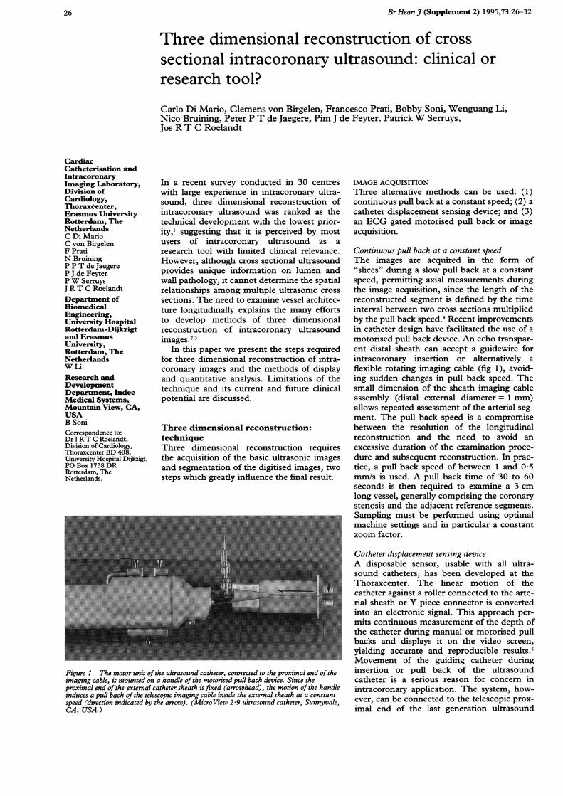
Figure 1 The motor unit of the ultrasound catheter, connected to the proximal end of theimaging cable, is mounted on a handle of the motorised pull back device. Since theproximal end of the external catheter sheath is fixed (arrowhead), the motion of the handleinduces a puUl back of the telescopic imaging cable inside the external sheath at a constantspeed (direction indicated by the arrow). (MicroView 2-9 ultrasound catheter, Sunnyvale,CA, USA.)
IMAGE ACQUISrTIONThree alternative methods can be used: (1)continuous pull back at a constant speed; (2) acatheter displacement sensing device; and (3)an ECG gated motorised pull back or imageacquisition.
Continuous pull back at a constant speedThe images are acquired in the form of"slices" during a slow pull back at a constantspeed, permittng axial measurements duringthe image acquisition, since the length of thereconstructed segment is defined by the timeinterval between two cross sections multipliedby the pull back speed.4 Recent improvementsin catheter design have facilitated the use of amotorised pull back device. An echo transpar-ent distal sheath can accept a guidewire forintracoronary insertion or alternatively aflexible rotating imaging cable (fig 1), avoid-ing sudden changes in pull back speed. Thesmall dimension of the sheath imaging cableassembly (distal external diameter = 1 mm)allows repeated assessment of the arterial seg-ment. The pull back speed is a compromisebetween the resolution of the longitudinalreconstruction and the need to avoid anexcessive duration of the examination proce-dure and subsequent reconstruction. In prac-tice, a pull back speed of between 1 and 0 5mm/s is used. A pull back time of 30 to 60seconds is then required to examine a 3 cmlong vessel, generally comprising the coronarystenosis and the adjacent reference segments.Sampling must be performed using optimalmachine settings and in particular a constantzoom factor.
Catheter displacement sensing deviceA disposable sensor, usable with all ultra-sound catheters, has been developed at theThoraxcenter. The linear motion of thecatheter against a roller connected to the arte-rial sheath or Y piece connector is convertedinto an electronic signal. This approach per-mits continuous measurement of the depth ofthe catheter during manual or motorised pullbacks and displays it on the video screen,yielding accurate and reproducible results.5Movement of the guiding catheter duringinsertion or pull back of the ultrasoundcatheter is a serious reason for concern inintracoronary application. The system, how-ever, can be connected to the telescopic prox-imal end of the last generation ultrasound
26

3-D reconstruction of2-D intracoronary ultrasound
catheter in order to measure the depth ofinsertion of the imaging core into the distalsheath.
ECG gated motorised pull back or imageacquisitionSystolic-diastolic movement of the imagingcatheter and cyclic changes of the vesseldimensions are major limitations for accuratethree dimensional reconstruction of lumenand vessel wall, suggesting consistent use ofend diastolic images for quantification.6 AnECG gated three dimensional reconstructioncan be obtained by using a stepping motorand a dedicated acquisition station. At theThoraxcenter we use the commercially avail-able Echoscan (TomTec, Munich, Germany)7which controls the stepping motor of the pullback device using steering logic which takesaccount of the variation of the heart cycle.Before acquisition, variables such as the dis-tance between consecutive transducer posi-tions (step resolution) and the length of thesegment studied (scan distance) are defined.The acquisition is started from the peak of theR wave and images are grabbed during thefollowing cardiac cycle at a speed of 25 framesper second. After this sequence the systemdetermines whether an individual R-R intervalfits in the predefined range. If the require-ments are fulfilled, the digitised frames arestored and the catheter is withdrawn up to thenext transducer position. Otherwise, theframes are rejected and a new sequence ofimages is* acquired at the same transducerposition, starting at the next R wave (fig 2).Images of successive cardiac cycles areacquired until the end of the scan distance isreached. The advantage of such an ECGgated image acquisition and pull back isthat the three dimensional reconstructioncan be shown in a cine loop format, enablingthe dynamic visualisation of the coronaryartery.
1000 ms 870 ms
Accepted Step
1340 ms 1000 ms 1000 ms
Rejected Accepted Step
R-R interval = 1000 ms ± 100 msRespiration gating = OFF
Figure 2 Schematics of the ECG gated acquisition during motorised pull back witdedicated stepping motor unit. Only the images obtained duning cardiac cycles ofpredetermined length are accepted, triggering a further movement of the catheter.
IMAGE SEGMENTATIONThe subsequent essential step after imageacquisition and digitisation is the image seg-mentation which distinguishes between theblood pool and structures of the vessel wall inall the digitised ultrasound images. The highfrequencies (.> 20 MHz), required to achievehigh resolution imaging of the vessel wall,induce a high echogenicity of the blood poolwhich impairs the automated detection of thelumen-intima boundary. A "hard" thresholdcannot be successfully applied in order toeliminate this interference because of theintensity overlap between the backscatterintensity of blood pool and vessel wall.The backscatter pattern of flowing blood
cells shows a speckled texture which variesover time, whereas the echo signal of the vesselwall shows a more fixed pattern. The bloodspeckle identification algorithm can be basedon this principle. The blood pool is identifiedusing statistical pattern recognition and thepixels identified as blood are removed. Animmediate appreciation of the accuracy ofblood subtraction is facilitated by the possibil-ity of colour encoding the vessel lumen dis-played in red. User interaction is allowed tomodify pattern recognition variables. Finally,manual correction of the individual cross sec-tional luminal contours can be performed. Anadvantage of this method is that no assump-tions on the lumen geometry are required,thus allowing segmentation of irregular lumenshapes such as may occur after coronary inter-ventions. Recently this method has been vali-dated in normal rabbit aortas.8An alternative segmentation approach is
the contour detection based on the applica-tion of a minimum cost algorithm that will bediscussed later.
THREE DIMENSIONAL RECONSTRUCTIONFull grey scale volume rendering has replacedprevious methods for three dimensionalreconstruction of intracoronary ultrasoundimages. The vessel can be displayed using avariety of computer generated two dimen-sional (transverse, longitudinal, oblique) ortrue three dimensional images such as lumencasts or cylindrical image formats which arecut lengthwise and opened (clam shell view),showing the intimal surface of the vessel.
ON LINE RECONSTRUCTION ANDQUANTIFICATION: THORAXCENTEREXPERIENCEAt the Thoraxcenter the EchoQuant system(Indec, Sunnyvale, CA, USA) is used for online three dimensional reconstruction, display,and quantitative analysis of intravascularultrasound images. The system operates on adedicated Intell Pentium 60 MI4Hz personal
L___ computer using the OS/2 operating system,digitising the analogue video image on line oroff line with a digitisation frame rate of 8-5images per second. During the image acquisi-tion (maximum 255 slices) the reconstructionof the longitudinal section is started and
h a immediately displayed on the screen. The ves-sel length traversed depends on the pull back
25 frames
27
Di Mario, von Birgelen, Prati, Soni, Li, Bruining, et al
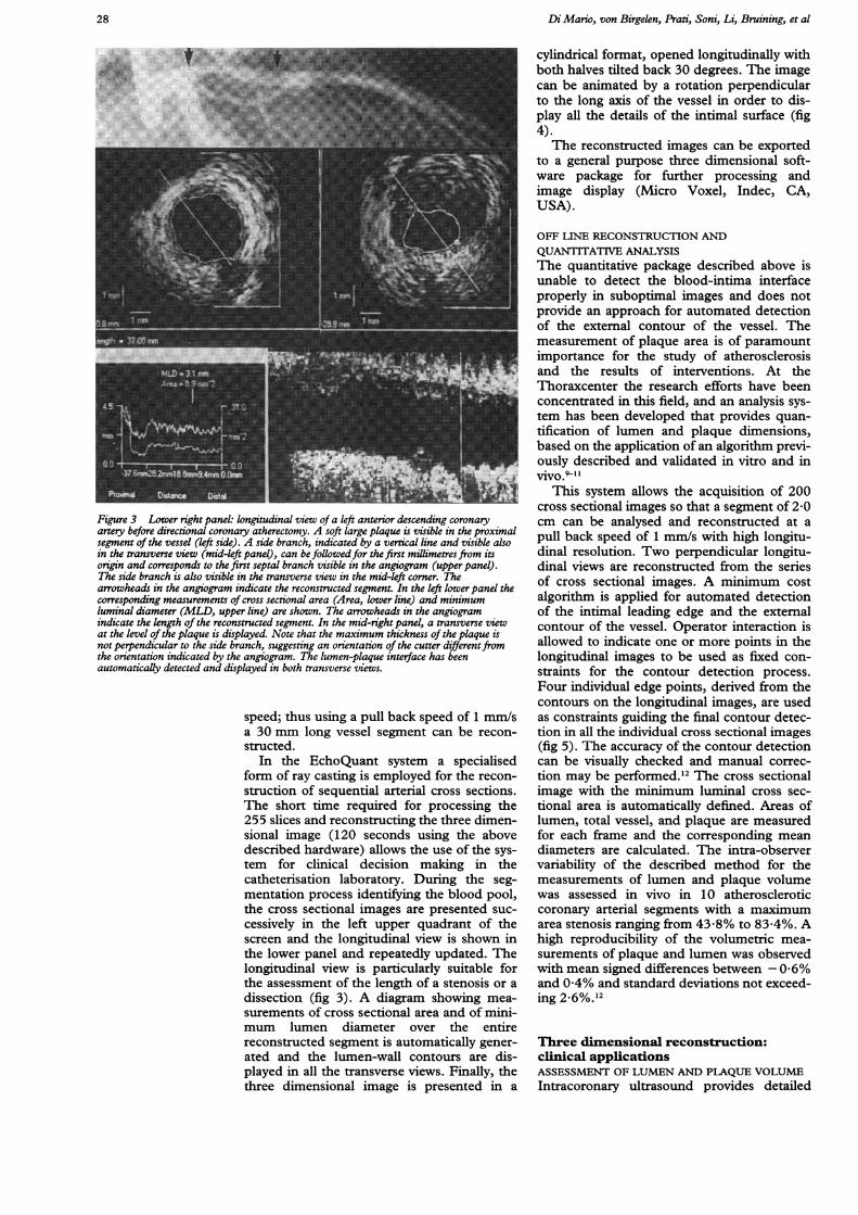
Figure 3 Lower right panel: longitudinal view of a left anterior descending coronaryartery before directional coronary atherectomy. A soft large plaque is visible in the proximalsegment of the vessel (left side). A side branch, indicated by a vertical line and visible alsoin the transverse view (mid-left panel), can be followedfor the first millimetres from itsorigin and corresponds to the first septal branch visible in the angiogram (upper panel).The side branch is also visible in the transverse view in the mid-left corner. Thearrowheads in the angiogram indicate the reconstructed segment. In the left lowerpanel thecorresponding measurements of cross sectional area (Area, lower line) and minimumluminal diameter (MLD, upper line) are shown. The arrowheads in the angiogramindicate the length of the reconstructed segment. In the mid-right panel, a transverse viewat the level of the plaque is displayed. Note that the maximum thickness of the plaque isnot perpendicular to the side branch, suggesting an orientation of the cutter differentfromthe orientation indicated by the angiogram. The lumen-plaque interface has beenautomatically detected and displayed in both transverse views.
speed; thus using a pull back speed of 1 mm/sa 30 mm long vessel segment can be recon-structed.
In the EchoQuant system a specialisedform of ray casting is employed for the recon-
struction of sequential arterial cross sections.The short time required for processing the255 slices and reconstructing the three dimen-sional image (120 seconds using the abovedescribed hardware) allows the use of the sys-tem for clinical decision making in thecatheterisation laboratory. During the seg-mentation process identifying the blood pool,the cross sectional images are presented suc-
cessively in the left upper quadrant of thescreen and the longitudinal view is shown inthe lower panel and repeatedly updated. Thelongitudinal view is particularly suitable forthe assessment of the length of a stenosis or adissection (fig 3). A diagram showing mea-
surements of cross sectional area and of mini-mum lumen diameter over the entirereconstructed segment is automatically gener-ated and the lumen-wall contours are dis-played in all the transverse views. Finally, thethree dimensional image is presented in a
cylindrical format, opened longitudinally withboth halves tilted back 30 degrees. The imagecan be animated by a rotation perpendicularto the long axis of the vessel in order to dis-play all the details of the intimal surface (fig4).The reconstructed images can be exported
to a general purpose three dimensional soft-ware package for further processing andimage display (Micro Voxel, Indec, CA,USA).
OFF LINE RECONSTRUCTION ANDQUANTITATIVE ANALYSISThe quantitative package described above isunable to detect the blood-intima interfaceproperly in suboptimal images and does notprovide an approach for automated detectionof the external contour of the vessel. Themeasurement of plaque area is of paramountimportance for the study of atherosclerosisand the results of interventions. At theThoraxcenter the research efforts have beenconcentrated in this field, and an analysis sys-tem has been developed that provides quan-tification of lumen and plaque dimensions,based on the application of an algorithm previ-ously described and validated in vitro and invivo.9-1I
This system allows the acquisition of 200cross sectional images so that a segment of 2x0cm can be analysed and reconstructed at apull back speed of 1 mm/s with high longitu-dinal resolution. Two perpendicular longitu-dinal views are reconstructed from the seriesof cross sectional images. A minimum costalgorithm is applied for automated detectionof the intimal leading edge and the externalcontour of the vessel. Operator interaction isallowed to indicate one or more points in thelongitudinal images to be used as fixed con-straints for the contour detection process.Four individual edge points, derived from thecontours on the longitudinal images, are usedas constraints guiding the final contour detec-tion in all the individual cross sectional images(fig 5). The accuracy of the contour detectioncan be visually checked and manual correc-tion may be performed.'2 The cross sectionalimage with the minimum luminal cross sec-tional area is automatically defined. Areas oflumen, total vessel, and plaque are measuredfor each frame and the corresponding meandiameters are calculated. The intra-observervariability of the described method for themeasurements of lumen and plaque volumewas assessed in vivo in 10 atheroscleroticcoronary arterial segments with a maximumarea stenosis ranging from 43x8% to 83x4%. Ahigh reproducibility of the volumetric mea-surements of plaque and lumen was observedwith mean signed differences between - 0-6%and 0-4% and standard deviations not exceed-ing 2.6%.12
Three dimensional reconstruction:clinical applicationsASSESSMENT OF-LUMEN AND PLAQUE VOLUMEIntracoronary ultrasound provides detailed
28

3-D reconstruction of 2-D intracoronary ultrasound
Figure 4 Right upper panel: cineangiogram ofa left anterior descending coronary artery3 months after implantation ofa Wallstent (Schneider, Bulach, Switzerland). Blackarrows indicate the segment reconstructed with three dimensional intracoronary ultrasound.Left upper panel: a cylindrical reconstruction of that artery is cut open and presented in aclam shell view. In the distal end (towards the observer), the echogenic wires of the stentare visible, with the presence ofa moderate intimal thickening inside the stent in the moredistal part. Lower panels: longitudinal view and corresponding area function (lower line)and diameter function (upper line) of the reconstructed segment. The progressive taperingof the vessel and the distal narrowing of the coronary lumen are clearly displayed andquantified. Note the saw fish appearance of the diameterffunction in the proximal segmentinduced by the systolic expansion of the vessel.
tomographic information about coronarylumen and plaque which are not availablewith angiography."314 Rosenfield et all5 haveproposed the application of automated edgedetection algorithms for the analysis of a threedimensional lumen cast. With this method a
rapid on line assessment of the minimumcross sectional area before and after interven-tions on peripheral arteries was possible.Matar et alP6 used a motorised pull back handleto obtain a uniform distance between consecu-tive cross sections in the examination of arter-ial specimens in vitro and of human coronaryarteries in vivo. The volumes of the recon-structed lumen correlated well with the histol-
ogy measurements and with the results ofbiplane quantitative angiography.The measurement ofplaque volume allows a
direct assessment of the changes of vasculardimensions induced by pharmacological ordietary therapy aiming at regression of athero-sclerosis'7 18 and by interventional procedures.Galli et al'8 compared the true plaque volumeof a vessel phantom and the measurementsbased on planimetry of consecutive cross sec-tions with the results of direct three dimen-sional reconstruction. Plaque volumesmeasured by three dimensional reconstruc-tion overestimated the true plaque volume ofthe phantom while more accurate measure-ments were obtained from direct planimetryof the echographic cross sections. The impor-tance of the algorithm used for image segmen-tation is documented by the accuratemeasurements obtained by Hausmann et al innormal rabbit aortas8 and by von Birgelen et alin vessel phantoms.'2The application of computerised systems of
automated edge detection for adventitial andlumen border'2 has the potential to increasethe reproducibility of the measurements ofplaque and lumen volume (r = 099 and r =0 97 respectively) and the correlation oflumen volume measurements obtained duringsubsequent independent pull back data sets(r = 099).19
ASSESSMENT OF INTERVENTIONSRationaleThe accurate detection of vessel dimensionand plaque characteristics provided by intra-coronary ultrasound can be used to select typeand size of device to be used and to guide theinterventions. On line three dimensionalreconstruction offers practical advantages incomparison with a conventional ultrasoundexamination. The on line longitudinal view ofthe stenotic segment before dilatation pro-vides immediate information on the length ofthe stenosis and on the diameter of the lumenand total vessel in the reference segment.Based on this information, the length anddiameter of balloon or device to be used canbe more easily selected. The comparisonbetween different cross sections (that is, refer-ence and stenosis) can be-performed by sim-ply moving a cursor and does not requirerepeated insertions of the ultrasound probe ortime consuming reviews of the video record-ings. The effects and mechanisms of interven-tions and of restenosis19-21 can be studiedusing a rigorous comparison of correspondingcross sections, provided that the pull backmanoeuvre has been started from the sameanatomical landmark (for example, the originof a side branch). The depth and length ofcalcification, an important determinant ofresults and complications of coronary inter-ventions,2-28 and the spatial geometry of dis-sections can be better determined.29-32
Clinical applicationFrom the on line and off line analysis of theintravascular ultrasound examination of 52peripheral and 22 coronary arteries Rosenfield
29
Di Mario, von Birgelen, IPrati, Soni, Li, Bruining, et al
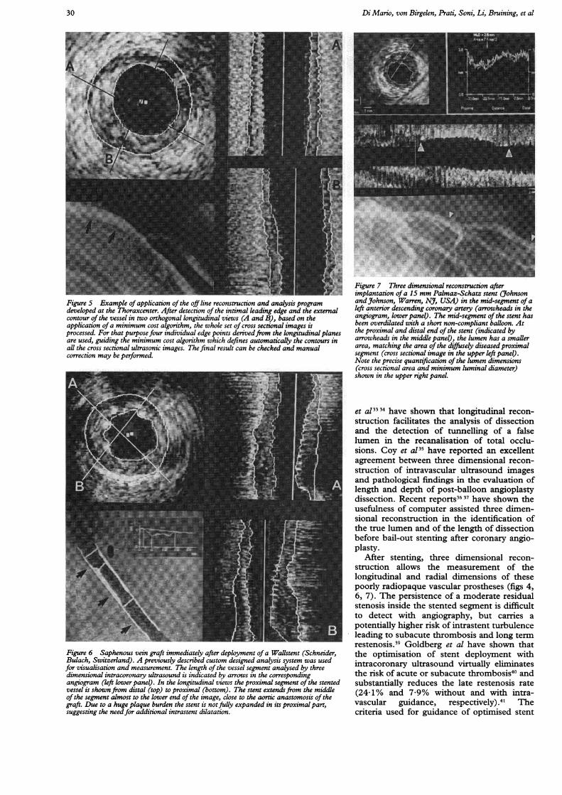
Figure 5 Example of application of the off line reconstruction and analysis programdeveloped at the Thoraxcenter. After detection of the intimal leading edge and the externalcontour of the vessel in two orthogonal longitudinal views (A and B), based on theapplication ofa minimum cost algorithm, the whole set of cross sectional images isprocessed. For that purpose four individual edge points derivedfrom the longitudinal planesare used, guiding the minimum cost algorithm which defines automatically the contours inall the cross sectional ultrasonic images. The final result can be checked and manualcorrection may be performed.
Figure 6 Saphenous vein graft immediately after deployment of a WaUlstent (Schneider,Bulach, Switzerland). A previously described custom designed analysis system was usedfor visualisation and measurement. The length of the vessel segment analysed by threedimensional intracoronary ultrasound is indicated by arrows in the correspondingangiogram (left lower panel). In the longitudinal views the proximal segment of the stentedvessel is shown from distal (top) to proximal (bottom). The stent extendsfrom the middleof the segment almost to the lower end of the image, close to the aortic anastomosis of thegraft. Due to a huge plaque burden the stent is notfully expanded in its proximal part,suggesting the needfor additional intrastent dilatation.
Figure 7 Three dimensional reconstruction afterimplantation ofa 15 mm Palmaz-Schatz stent (JohnsonandJohnson, Warren, NJ, USA) in the mid-segment ofaleft anterior descending coronary artery (arrowheads in theangiogram, lower panel). The mid-segment of the stent hasbeen overdilated with a short non-compliant balloon. Atthe proximal and distal end of the stent (indicated byarrowheads in the middle panel), the lumen has a smallerarea, matching the area of the diffusely diseasedproximalsegment (cross sectional image in the upper left panel).Note the precise quantification of the lumen dimensions(cross sectional area and minimum luminal diameter)shown in the upper right panel.
et al3334 have shown that longitudinal recon-struction facilitates the analysis of dissectionand the detection of tunnelling of a falselumen in the recanalisation of total occlu-sions. Coy et a!35 have reported an excellentagreement between three dimensional recon-struction of intravascular ultrasound imagesand pathological findings in the evaluation oflength and depth of post-balloon angioplastydissection. Recent reports36 37 have shown theusefulness of computer assisted three dimen-sional reconstruction in the identification ofthe true lumen and of the length of dissectionbefore bail-out stenting after coronary angio-plasty.
After stenting, three dimensional recon-struction allows the measurement of thelongitudinal and radial dimensions of thesepoorly radiopaque vascular prostheses (figs 4,6, 7). The persistence of a moderate residualstenosis inside the stented segment is difficultto detect with angiography, but carries apotentially higher risk of intrastent turbulenceleading to subacute thrombosis and long termrestenosis.39 Goldberg et al have shown thatthe optimisation of stent deployment withintracoronary ultrasound virtually eliminatesthe risk of acute or subacute thrombosis40 andsubstantially reduces the late restenosis rate(24-1% and 7 9% without and with intra-vascular guidance, respectively).4' Thecriteria used for guidance of optimised stent
30
3-D reconstruction of 2-D intracoronary ultrasound
implantation can be applied more easily andmore reliably to a three dimensional recon-structed image, displaying the entire stentedsegment and the adjacent reference segments(fig 6).
Intracoronary ultrasound is frequently usedfor guidance of directional atherectomy.Recent reports have shown that three dimen-sional reconstruction facilitates the orienta-tion of the cutter in relation to side branches(fig 3) and the detection of deep cuts or spiralcuts from rotation of the atherectomy catheterduring plaque removal.42 The clinical useful-ness of preintervention intracoronary ultra-sound in planning and guiding a variety oftranscatheter treatments has recently beenreported by Mintz et al from Washington, acentre with experience of thousands of ultra-sound examinations consistently acquiredwith a motorised pull back system.43 Theseworkers have suggested a specific usefulnessof on line three dimensional reconstruction inthe evaluation before intervention.43
LimitationsThe first critical factor determining the resultsof the three dimensional reconstruction is thequality of the acquired echographic cross sec-tions. An insufficient delineation of the inti-mal border or the absence or incompletecircumferential detection of the plaque-adventitia interface precludes automatedquantitative measurements of lumen andplaque volumes. Calcium shadowing or intra-luminal flaps orientated tangentially to theultrasound beam may also obscure the under-lying wall.44 The axial resolution of the cur-rent ultrasound probes is reduced in the farfield, thus limiting the detection of intimalthickening and of lipid or calcium depositinside the plaque,45 and the lateral and out ofplane resolution is limited by the physicaldimensions of the piezoelectric crystal.46The use of cross sectional images distorted
by the non-uniform rotation of the echo-graphic transducer or by a non-coaxial posi-tion of the catheter inside the lumen maycreate complex artefacts in the reconstructedimage.The presence of a fixed distance between
adjacent cross sections is mandatory but diffi-cult to achieve. The use of a motorised pullback or of a sensor measuring catheter dis-placement cannot completely prevent anuneven speed during the pull back, sincebends in the ultrasound catheter may induce adifference between movement of the tip andof the proximal end of the catheter. Anotherpotential source of error is the rotation of thecatheter during the pull back, causing a mis-match between the orientation of sequentialimages. The use of a miniaturised receivingantenna located at the tip of the ultrasoundcatheter and of an external electromagnetictransmitting antenna in a plane perpendicularto the catheter axis has been proposed as apossible method to measure the orientationof the intracoronary ultrasound catheter.47Curvatures of the vessel also induce a pre-
dictable distortion of the three dimensionalimage which is reconstructed along a straightline through the centre of successive cross sec-tions. Expansion or compression of plaquesmay result in an overestimation or underesti-mation of the volumes measured from thereconstructed image. A simultaneous digitisedbiplane fluoroscopic tracking of the radio-opaque transducer and catheter tip has thepotential to overcome this limitation but inpractice is applicable only for research pur-poses.48 When an accurate reconstruction ofthe curvature of the vessel is acquired, com-puter simulation can be applied to reconstructthe arterial flow profile three dimensionally.49These models can obviate the need of a directmeasurement of flow velocity in segmentswith a non-uniform velocity profile (curva-tures, stenosis) in which the assessment is dif-ficult also with state of the art intracoronaryultraminiaturised probes.50 51 The study offlow disturbances is of great interest in evalu-ating the relationship between location of ath-erosclerotic plaque and wall stress in vivo anddetecting the persistence of alterations in theflow field after interventions which may facili-tate wall thrombosis and trigger the restenosisprocess.The systolic expansion of the coronary ves-
sel and the movement of the catheter insidethe vessel during the cardiac cycle generate acharacteristic saw fish appearance of the ves-sel, more evident in arteries with large motilitysuch as mid-right coronary arteries and bypassgrafts. Methods of electrocardiographic gatingof the image acquisition can eliminate theseartefacts, but require at present a significantincrease of the examination time and the com-plexity of the instrumentation.
ConclusionsThe availability of on line three dimensionalreconstruction allows the technique to beapplied for guidance and immediate assess-ment of coronary interventions. High qualitycross sectional images are mandatory toachieve an accurate detection of vessel lumenand plaque. Algorithms for blood subtractionand quantitative measurement of lumen andplaque volumes can be applied. Inaccuraciesin image acquisition may induce artefacts ofthe reconstructed image, but our experienceindicates that computer generated longitudi-nal and transverse images derived from thethree dimensional image dataset facilitateinterpretation and clinical application of intra-coronary ultrasound.
1 Hodgson J McB. Intracoronary ultrasound. In: Faxon DP,Holmes DR, Sanborn TA, Schatz RA, eds. Interventionalcardiology newsletter, vol 2-2. New York: ElsevierScience, 1994:12-13.
2 Kitney RI, Moura L, Straughan K. Three-dimensionalintravascular ultrasound. In: Bom N, Roelandt JRTC,eds. Intravascular ultrasound. Dordrecht: Kluwer, 1989:135-46.
3 Roelandt JRTC, Di Mario C, Pandian NG, Li W, KeaneD, Slager CS, et al. Three-dimensional reconstruction ofintracoronary ultrasound images: rationale, approaches,problems and directions. Circulation 1994;90:1044-55.
4 Mintz GS, Keller MB, Fay FG. Motorized IVUS trans-ducer pull-back permits accurate quantitative axial mea-surements (abstr). Circulation 1992;86:I-323.
31
Di Mario, von Birgelen, Prati, Soni, Li, Bruining, et al
5 Gussenhoven EJ, van der Lugt A, Van Strijen M, Li W,Kroeze H, The SHK, et al. Displacement sensing deviceenabling accurate documentation of catheter tip posi-tion. In: Roelandt J, Gussenhoven EJ, Bom N, eds.Intravascular ultrasound 1993. Dordrecht: Kluwer, 1993:157-66.
6 Weissman NJ, Palacios IF, Weyman AE. Dynamic expan-sion of coronary arteries. Implications for intravascularultrasound measurement (abstr). Y Am Coil Cardiol1994;23:242A.
7 Roelandt JRTC, Ten Cate FJ, Vletter WB, Taams MA.Ultrasonic dynamic three dimensional visualization ofthe heart using a vario-plane transesophageal imagingtransducer (Varioplane Echo-CT). Am SocEchocardiogr 1994;7:217-9.
8 Hausmann D, Friedrich G, Sudhir K, Mullen WL, Soni B,Fitzgerald PJ, et al. 3D intravascular ultrasound imagingwith automated border detection using 2-9 F Catheters(abstr). Am Coil Cardiol 1994;23:174A.
9 Li W, Gussenhoven WJ, Zhong Y, The SHK, Di Mario C,Madretsma S, et al. Validation of quantitative analysis ofintravascular ultrasound images. Int Card Imaging1991;6:247-54.
10 Di Mario C, The SHK, Madretsma S, van Suylen RJ,Wilson R, Bom N, et al. Detection and characterization ofvascular lesions by intravascular ultrasound. An in-vitrocorrelative study with histology. Y Am Soc Echocardiogr1992;19:135-46.
11 Li W, Bosch JG, Zhong Y, von Urk H, Gussenhoven EJ,Mastik F, et al. Image segmentation and 3D reconstruc-tion of intravascular ultrasound images. Acoustic Imaging1993;20:489-96.
12 Birgelen von C, Di Mario C, Li W, Camenzind E, OzakiY, de Feyter PJ, et al. Volumetric quantification in intra-coronary ultrasound: validation of a new automatic con-tour detection method with integrated user interaction(abstr). Circulation 1994;90:I-550.
13 Escaned J, Baptista J, Di Mario C, Ozaki Y, RoelandtJRTC, Serruys PW, et al. Detection of coronaryatheroma by quantitative angiography: insights gainedfrom intracoronary ultrasound imaging (abstr). AmColl Cardiol 1994;23:174.
14 Ge J, Erbel R, Zamorano J, Koch L, Keamey P, Gorge G,et al. Coronary artery remodeling in atherosclerotic dis-ease: an intravascular ultrasonic study in vivo. CoronaryArtery Dis 1993;4:981-6.
15 Rosenfield K, Kaufman J, Losordo DW, Isner JM. Lumencast analysis: a quantitative format to expedite on-lineanalysis of 3D-intravascular ultrasound images (abstr).J7Am Coll Cardiol 1992;19:115A.
16 Matar FA, Mintz GS, Douek PC, Leon MB, Popma JJ.Three-dimensional intravascular ultrasound: a new stan-dard for vessel lumen volume measurement? (abstr).JAm Coil Cardiol 1992;19:382A.
17 Gupta M, Connolly AJ, Zhu BQ, Sievers RE, Sudhir K,Sun YP, et al. Quantitative analysis of progression andregression of atherosclerosis by intravascular ultrasound:validation in a rabbit model (abstr). Circulation 1992;86:I-518.
18 Galli FC, Sudhir K, Kao AK, Fitzgerald PJ, Yock PG.Direct measurement of plaque volume by three-dimen-sional ultrasound: potential and pitfalls (abstr). AmColl Cardiol 1992;19:115A.
19 Dhawale P, Rasheed Q, Berry J, Hodgson J. Quantificationof lumen and plaque volume with ultrasound: accuracyand short term variability in patients (abstr). Circulation1994;90:I-1 64.
20 Braden GA, Herrington DM, Downes TR, Kutcher MA,Little WC. Qualitative and quantitative contrasts in themechanisms of lumen enlargement by coronary balloonangioplasty and directional coronary atherectomy. JXAmCoil Cardiol 1994;23:40-8.
21 Tenaglia AN, Buller CE, Kisslo KB, Stack RS, DavidsonCJ. Mechanisms of balloon angioplasty and directionalcoronary atherectomy as assessed by intracoronary ultra-sound. Am Coil Cardiol 1992;20:685-91.
22 Suneja R, Nair NR, Reddy KG, Rasheed Q, Sheehan HM,Hodgson JM. Mechanisms of angiographically success-ful directional coronary atherectomy. Am Heart 1993;126:507-14.
23 Di Mario C, Camenzind E, Ozaki Y, Gil R, von BirgelenC, Umans V, et al. Is the mechanism of restenosis deviceindependent? Serial assessment with intracoronary ultra-sound (abstr). Circulation 1994:90:I-24.
24 Mintz GS, Popma JJ, Pichard AD, Kent KM, Satler LF,Painter JA, et al. Mechanism of late arterial response totranscatheter therapy: a serial quantitative angiographicand intravascular ultrasound study (abstr). Circulation1994;90:I-24.
25 The GUIDE trial investigators. IVUS-determined predic-tors of restenosis in PTCA and DCA: an interim reportfrom the GUIDE trial, Phase II (abstr). Circulation1994;90:I-25.
26 Honye J, Mahon DJ, White CJ, Ramee SR, Wallis JB, Al-Zarka A, et al. Morphological effects of coronary balloonangioplasty in vivo assessed by intravascular ultrasoundimaging. Circulation 992;85:1012-25.
27 Fitzgerald PJ, Ports TA, Yock PG. Contribution of local-ized calcium deposits to dissection after angioplasty. Anobservational study using intravascular ultrasound.Circulation 1992;86:64-70.
28 Potkin BN, Keren G, Mintz GS, Douek PC, Pichard AD,Satler LF, et al. Arterial response to balloon coronary
angioplasty: an intravascular ultrasound study. JAm CollCardiol 1992;20:942-5 1.
29 The SHK, Gussenhoven EJ, Zhong Y, Li W, van EgmondF, Pieterman H, et al. Effect of balloon angioplasty onfemoral artery evaluated with intravascular ultrasoundimaging. Circulation 1992;86:483-93.
30 Losordo DW, Rosenfield K, Pieczek A, Baker K, HardingM, Isner JM. How does angioplasty work? Serial analysisof human iliac arteries using intravascular ultrasound.Circulation 1992;86:1845-58.
31 Werner GS, Sold G, Buchwald A, Wiegand V. Intra-vascular ultrasound imaging of human coronary arteriesafter percutaneous transluminal angioplasty: morpho-logic and quantitative assessment. Am HeartJ 1991;122:212-20.
32 Tenaglia AN, Buller CE, Kisslo KB, Phillips HR, StackRS. Intracoronary ultrasound predictors of adverse out-comes after coronary artery interventions. _J Am CoilCardiol 1992;20: 1385-90.
33 Rosenfield K, Losordo DW, Ramaswamy K, Isner JM.Three-dimensional reconstruction of human coronaryand peripheral arteries from images recorded duringtwo-dimensional intravascular ultrasound examination.Circulation 1991;84:1938-56.
34 Rosenfield K, Kaufman J, Pieczek A, Langevin RE, Razvi S,Isner JM. Real-time three-dimensional reconstruction ofintravascular ultrasound images of iliac arteries. Am JCardiol 1992;70:412-5.
35 Coy KM, Park JC, Fishbein MC, Laas T, Diamond GA,Adler L, et al. In vitro validation of three-dimensionalintravascular ultrasound for the evaluation of arterialinjury after balloon angioplasty. JAm Coil Cardiol 1992;20:692-700.
36 Cavaye DM, White RA, Lerman RD, Kopchock GE,Tabbara MR, Cormier F, et al. Usefulness of intravas-cular ultrasound imaging for detecting experimentallyinduced aortic dissection in dogs and for determiningthe effectiveness of endoluminal stenting. Am J Cardiol1992;69:705-7.
37 Schryver TE, Popma JJ, Kent KM, Leon MB, Mintz GS.Use of intracoronary ultrasound to identify the truecoronary lumen in chronic coronary dissection treatedwith intracoronary stenting. Am J Cardiol 1992;69:1107-8.
38 Nakamura S, Colombo A, Gaglione A, Almagor Y,Goldberg SL, Maiello L, et al. Intracoronary ultrasoundobservations during stent implantation. Circulation 1994;89:2026-34.
39 Mudra H, Klauss V, Blasini R, Kroetz M, Rieber J, RegarE, et al. Ultrasound guidance of Paimaz-Schatzintracoronary stenting with a combined intravascularultrasound balloon catheter. Circulation 1994;90:1252-61.
40 Goldberg SL, Colombo A, Nakamura S, Almagor Y,Maiello L, Tobis JM. Benefit of intracoronary ultra-sound in the deployment of Palmaz Schatz stents. J AmColl Cardiol 1994;24:996-1003.
41 Goldberg SL, Colombo A, Almagor Y, Hall P, Maiello L,Nakamura S, et al. Has the introduction of intravascularultrasound guidance led to different clinical results in thedeployment of intracoronary stents? (abstr.) Circulation1994;90:I-610.
42 Smucker ML, Kil D, Sarnat WS, Howard PF. Is three-dimensional reconstruction a gimmick or a useful clini-cal tool? Experience in coronary atherectomy (abstr).JfAm Coll Cardiol 1992;19:115A.
43 Mintz GS, Pichard AD, Kovach JA, Kent KM, Satler LF,Javier SP, et al. Impact of preintervention intravascularultrasound imaging on transcatheter treatment strategiesin coronary artery disease. Am Jf Cardiol 1994;73:423-30.
44 Di Mario C, Madrestma S, Linker D, The SHK, Bom N,Serruys PW, et al. The angle of incidence of the ultra-sonic beam: a critical factor for the image quality inintravascular ultrasound. Am HeartJ 1993;125:442-8.
45 Peters JC, Wouter EM, Miek G, Havenith JE, RijsteborghH, Allard C, et al. Histopathological validation of intra-coronary ultrasound imaging. Jf Am Soc Echocardiogr1994;7:230-41.
46 Benkeser PJ, Churchwell AL, Lee C, Abouelnasr DM.Resolution limitations in intravascular ultrasound imag-ing. JAm Soc Echocardiogr 1993;6:158-65.
47 Koch L, Kearney P, Erbel R, Roth Th, Ge J, Brennecke R,et al. Three dimensional reconstruction of intracoronaryultrasound images: roadmapping with simultaneouslydigitised coronary angiograms. IEEE Proc ComputCardiol 1993:89-91.
48 Aretz HT, Gregory KW, Martinelli MA, Gregg RE, LedetEG, Haase WC. Ultrasound guidance of laser atherec-tomy. IntJ Cardiac Imaging 1991;6:231-7.
49 Burrel J, McDonald AH, Rothman MT. 3-D computervisualization of arteries and blood flow-in vitro and invivo. Comput Cardiol 1994:41-6.
50 Di Mario C, Meneveau N, Gil R, de Jaegere P, de FeyterPJ, Slager CJ, et al. Maximal blood flow velocity insevere coronary stenoses measured with a Dopplerguidewire. Limitations for the applications of the conti-nuity equation in the assessment of stenosis severity. AmJ Cardiol 1993;71:54-61D.
51 Serruys PW, di Mario C, Kern MJ. IntracoronaryDoppler. In: Topol EJ, ed. Textbook of intermentional car-
diology, 2nd ed. Philadelphia: WB Saunders, 1994:1069-121.
32