three-dimensional thermo-fluid-electrochemical modeling … library/research/coal/energy...
TRANSCRIPT

Three-Dimensional Thermo-Fluid-Electrochemical Modeling of Planar SOFC Stacks Using the STAR-CD
Commercial CFD Code
Three-Dimensional Thermo-Fluid-Electrochemical Modeling of Planar SOFC Stacks Using the STAR-CD
Commercial CFD CodeK.P. Recknagle, R.E. Williford, L.A. Chick, D.R. Rector, M.A. Khaleel
Presented by: Kurt Recknagle

2
OUTLINEOUTLINEOUTLINE
BackgroundMethodology GeometrySTAR-CD / ProstarUser SubroutinesParallel ProcessingPost ProcessingFurther Topics
Transition modelingMultiple Cell Stacks

3
BackgroundBackgroundBackground
The Planar SOFC is a high temperature (600-1000 °C), fuel cell that is favorable for use in many applications due to it’s compactness: active areas can be stacked in close proximity to yield high power densityThe primary mechanical design challenge related to high temperature operation: the design must minimize the non-uniform temperature distributions that contribute to stress in the planar componentsFuel utilization, temperature distribution, and average cell temperature are controlled by the delivery rate and the temperatures of fuel and air to the cell

4
Background (continued)Background (continued)Background (continued)
Increased fuel flow increases uniformity of the reaction rates on the active area but decreases fuel utilization. Decreased fuel flow increases fuel utilization, but can cause local fuel depletion and cold spots that exacerbate temperature non-uniformities. Management of the flow of air and fuel, and the distribution of each, is critical to stable operation of the cell. Reliable prediction of temperature distribution, using a Thermal-Fluid-Electrochemical (TFE) simulation tool, is key to successful analysis of potential designs
5
Background (continued)Background (continued)Background (continued)
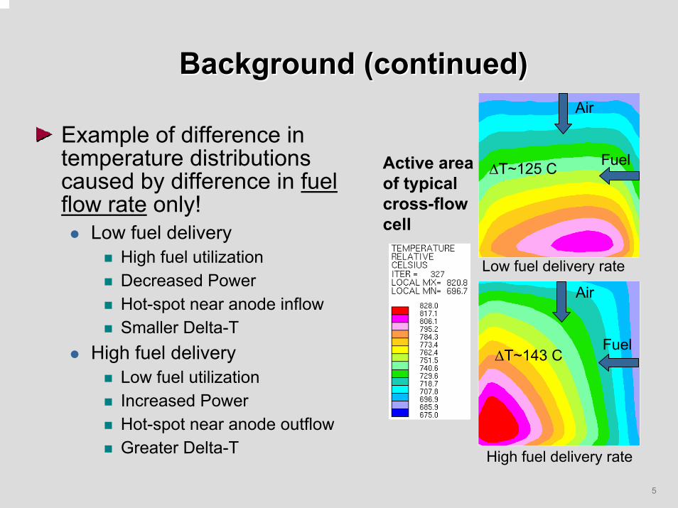
Example of difference in temperature distributions caused by difference in fuel flow rate only!
Low fuel deliveryHigh fuel utilizationDecreased PowerHot-spot near anode inflowSmaller Delta-T
High fuel deliveryLow fuel utilizationIncreased Power Hot-spot near anode outflowGreater Delta-T
Low fuel delivery rate
High fuel delivery rate
Air
Air
Fuel
Fuel∆T~143 C
∆T~125 CActive areaof typical cross-flow cell

6
Background (continued)Background (continued)Background (continued)
Geometry is also key in establishing a well-operating cell. Distributions of Fuel & Temperature, and the fuel utilization are effected by:
Orientations of the fuel and airflows, Mass and dimensions of the cell components,Dimensions of flow channels and manifolds.
In order to efficiently develop and optimize planar SOFC stacks, it is convenient to experiment numerically with the effects of geometric configurations on operation and performance. Will see examples of geometric effects later in this presentation.

7
Methodology:commercial code as platform
Methodology:Methodology:commercial code as platformcommercial code as platform
Our methodology couples a validated electrochemistry calculation method (Chick et al, “Experimentally-Calibrated, Spreadsheet-Based SOFC Unit-Cell Performance Model”) with the commercial computational fluid dynamics code STAR-CD (Computational Dynamics Ltd.).The resulting modeling tool is suitable for predicting the flow, distribution, composition, and utilization of anode and cathode gases, and the distributions of temperature and electric current in planar SOFC stacks with arbitrary three-dimensional geometries.Presently, a FEA code is used to solve the stress distributions.

8
Methodology: Why use commercial code as platform for TFE calculations?
Methodology: Methodology: Why use commercial code as Why use commercial code as platform for TFE calculations?platform for TFE calculations?
Built-in Capabilities to create complex cell geometriesEase in creating and comparing various flow configuration cases Enables parametric study of design features
Built-in models to yield accurate prediction of scalar distributions including the temperature
Transport equations for multi-component gaseous fluid streamsHeat transfer models accommodate variable fluid stream properties (eg. 5:1 increase in fuel density from inflow to outflow boundary effects capacity to remove heat)
Built-in models to calculate thermally induced stresses in solid parts
Presently limited to finite element analysis codes

9
Methodology:Hydrogen Combustion and Gas Water Shift Reaction
Methodology:Methodology:Hydrogen Combustion and Hydrogen Combustion and Gas Water Shift ReactionGas Water Shift Reaction
CathodeElectrolyte
Anode
Air Channel(multiple "Z" cells)
H2 H2O
O2- (2)
(1) CO + H2O -> H2 + CO2
(2) H2 + 1/2O2 -> H2O
(1)
(O2, N2, …)
(H2, H2O, CO, CO2, CH4)
Z
Fuel Channel(multiple "Z" cells)
(Single "Z" cellThrough PEN)
Oxygen ions from the cathode side diffuse through electrolyte to the electrolyte-anode interfaceHydrogen from the anode combusts with the oxygen and frees electrons which travel along the cell to an external circuit while water vapor generated by the combustion diffuses back to the anode sideAt the surface of the anode, the water vapor reacts with CO in the Gas-Water-Shift reaction generating more hydrogen and CO2In the calculations, the shift reaction and combustion are assumed to be at equilibrium

10
Methodology: The Shift Reaction Procedure
Methodology: Methodology: The Shift Reaction ProcedureThe Shift Reaction Procedure
Assume that chemical equilibrium exists at every locationCalculate the target (thermo-dynamic) equilibrium coefficient using
Calculate the actual equilibrium coefficient using
Adjust the shift reaction rate based on the difference between the twoWhen steady, solution is converged
∆−∆+∆−=
RTCOGOHGCOGKeq
)()()(exp 22
Keq =CO[ ] H2O[ ]CO2[ ]H2[ ]

11
Methodology:Electrochemistry - The I-V Relation
Methodology:Methodology:Electrochemistry Electrochemistry -- The IThe I--V RelationV Relation
V(i) = Enernst– iRi– b sinh-1(i/2i0) + (RT/4F)ln(1-i/iO2) + (RT/2F)ln(1-i/iH2) – (RT/2F)ln[1+p0
H2i/(p0
H2OiH2)]
Nernst potential Ohmic resistancesCathode Activation PolarizationCathode Concentration Pol.Anode Concentration Pol.Anode Concentration Pol.
Term Description
Nernst potential Enernst = RT/4F ln(Po2cath/Po2anode)Ohmic resistances R = Rp + Re + Rn + RbipolarCathode Activation Pol. b, iO = Butler-Volmer parametersCathode Concentration Pol. iO2 = cathode limiting current densityAnode Concentration Pol. iH2 = anode limiting current densityAnode Concentration Pol. p0
H2O = partial pressure of water vapor
Model Parameters –Adjusted based on experimental cell data collected at PNNL

12
Methodology: STAR-CD/EC Single-Cell Stack
Methodology: Methodology: STARSTAR--CD/EC SingleCD/EC Single--Cell Stack Cell Stack
In the calculations, STAR-CD solves the Navier-Stokes and transport equations to obtain the flow, species concentrations and temperatures at each time step.The electrochemistry module calculates the local current distribution based on the applied voltage and local conditions. The current is used to calculate the local hydrogen combustion rates.The shift reaction rates are adjusted such that equilibrium conditions are satisfied at every location in the cell.Heat generation rates and species source rates are supplied to STAR-CD based on the local hydrogen combustion and shift reaction rates.Species concentration and temperature distributions are calculated for the next time step in STAR-CD.

13
Methodology: The Spread Sheet, Chick, et al
Methodology: Methodology: The Spread Sheet, Chick, et alThe Spread Sheet, Chick, et al
Spread sheet plots performance data from tests of a particular cell.Parameters of the I-V relation are adjusted to best fit the data.Thus a “cell specific” I-V relation is created.Electrochemistry routine in STAR-CD replicates the I-V relation determined by the spread sheet
Single Cell Data
0.4
0.5
0.6
0.7
0.8
0.9
1
1.1
0 0.5 1 1.5 2
Current Density, A/cm2
Cel
l Vol
tage
, V
800°C, 97%H2750°C, 97%H2700°C, 97%H2650°C, 97%H2Model, T=850Model, T=800Model, T=750Model, T=700Model, T=650

14
Model Geometry –Cross-Flow
Planar SOFC
Model Geometry Model Geometry ––CrossCross--FlowFlow
Planar SOFCPlanar SOFCThe repeating unit of a planar SOFC stack is constructed of a Positive electrode-Electrolyte-Negative electrode (PEN) and interconnect plates “stacked” together. Fig. 1 shows a schematic of an interconnect plate displayed as being transparent to show top and bottom features.The active cell area in Fig.1 is that formed by the intersection of air and fuel flows in the X-Y plane. A single-cell stack is formed when interconnects, similar to that in Fig.1, are placed above and below a PEN. Fig. 2 shows a partial schematic view of a vertical slice through a Y-Z plane of a multiple-cell, cross-flow stack. Air flows along the Y-direction. Fuel flow is along the X-direction (orthogonal to the page). The location of a cell unit along Z is shown at left in the figure.
Air
AirFuel
FuelX
Y
Z
Fuel
Air
PEN
Z
Interconnect
Interconnect
Cell Unit
Fuel
Air
PEN
Fuel
Air
PEN
Y
Fig.1. Schematic view of a typical cross-flow planar interconnect plate.
Fig. 2. Schematic section view of a typical cross-flow stack. Xs in the fuel region represent fuel flow vectors perpendicular to the page.
15
Specifying “Active” Elements for a STAR-CD Electrochemistry
Calculation
Specifying “Active” Elements Specifying “Active” Elements for a STARfor a STAR--CD Electrochemistry CD Electrochemistry
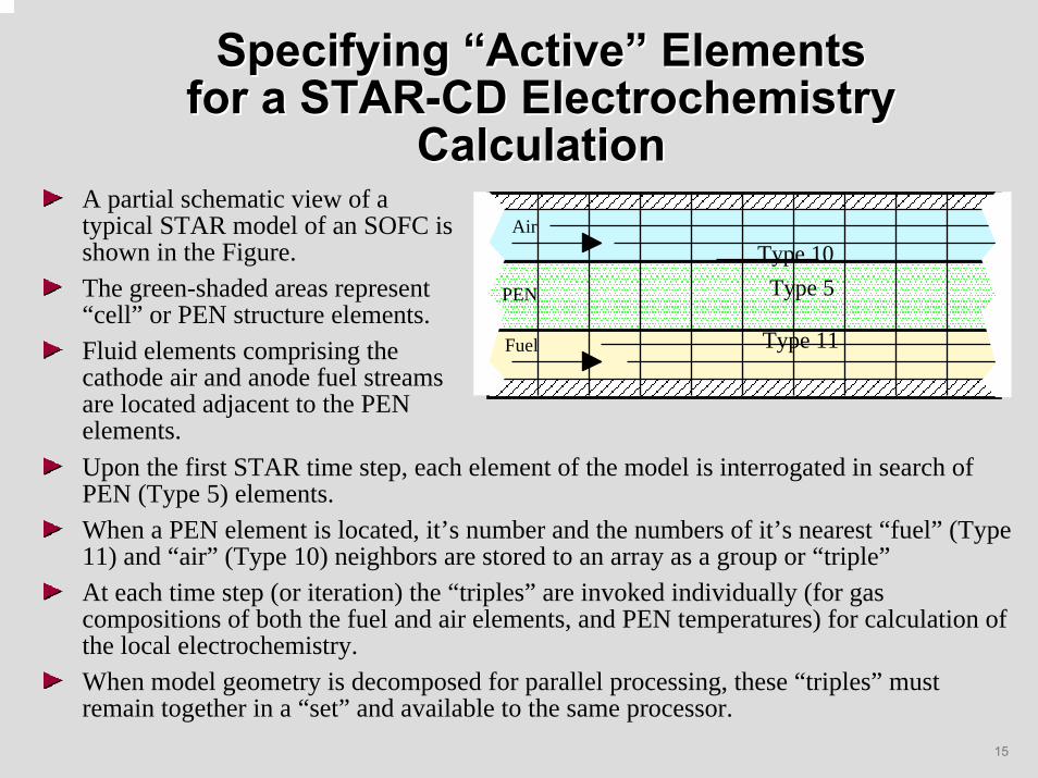
CalculationCalculationA partial schematic view of a typical STAR model of an SOFC is shown in the Figure. The green-shaded areas represent “cell” or PEN structure elements. Fluid elements comprising the cathode air and anode fuel streams are located adjacent to the PEN elements.
Fuel
Air
PEN
Type 10
Type 5
Type 11
Upon the first STAR time step, each element of the model is interrogated in search of PEN (Type 5) elements. When a PEN element is located, it’s number and the numbers of it’s nearest “fuel” (Type 11) and “air” (Type 10) neighbors are stored to an array as a group or “triple”At each time step (or iteration) the “triples” are invoked individually (for gas compositions of both the fuel and air elements, and PEN temperatures) for calculation of the local electrochemistry. When model geometry is decomposed for parallel processing, these “triples” must remain together in a “set” and available to the same processor.

16
Typical Cross-Flow CellConfiguration & STAR-CDTypical CrossTypical Cross--Flow CellFlow Cell
Configuration & STARConfiguration & STAR--CDCDStart PROSTAR (pre- and post-processor for the STAR-CD code)
prostar xm &Model geometry view
cset all cplot
Locate type 5, 10, and 11 cells discussed in previous slide.cset subset type 5 10 5cset add type 11cplot
View the remaining cell types and materials in the model to understand how model geometry is assembled
Use ctab button, and create new cell sets for viewing

17
Single-Cell Stack Model Boundary Conditions
SingleSingle--Cell Stack Model Boundary Cell Stack Model Boundary ConditionsConditions
Insulatedcontainer
CirculatingAir in Gap
SOFC Stack
Single-cellStack modeldomain
Fuel (or)Air IN
Fuel (or) Air OUT
Cyclic Boundary conditions on top and bottom of single cell stack model (ie. cell resides within larger stack)Convection and Gap Radiation heat transfer to/from perimeter walls of modelConstant Inflow boundary flow rates with variable temperature to control to desired operating temperature

18
Problem setup in ProstarProblem setup in ProstarProblem setup in Prostar
“Select Analysis Features” – Steady State for this case, can be run in Transient mode “Create and Import Geometry” – Import Cad drawings, etc.“Create and Import Grids” –
Import meshes from ANSYS, Ideas, ICEM, Patran, Nastran, etc. Create 2-D or 3-D meshes from scratch.
“Check and Fix the grid” – warped faces, obtuse angles, zero or negative volumes, etc.“Locate Boundaries” – allows user to create boundaries on the model. Boundaries include inlet, outlet, pressure, symmetric, cyclic, wall, attach (for moving mesh), etc.
Discuss use of element “sets” for geometric domain decomposition and parallel processing (recall discussion of “triples” being intact within a “set”)

19
Problem setup in Prostar (cont.)Problem setup in Prostar (cont.)Problem setup in Prostar (cont.)
“Thermo physical Models and Properties” – define the physical characteristics of solids, fluids, species within the gas mixture, and porous media. Initial conditions, reference values, etc.
Thermal Options – conjugate heat transfer (solid conduction coupled to fluid convection) is on.Liquids and Gases – molecular properties – Ideal gas density and multi-component specific heat.Turbulence model – laminar in this example caseThermal model – temperature calculation onAdditional scalars – active scalars used to setup the gaseous mixtures, and passive ones to store current density, and heat generation rate
Molecular Properties – molecular weight, density, specific heat, viscosity, conductivity, etc.Binary Properties – Diffusivity, Schmidt Number (kinetic viscosity) / (molecular diffusivity)Initialization – calculate the mass fraction of the gas species in the fuel (and air) mixture starting with mole fractions. One option is to use the utility spreadsheet “fuelconccalcGAScycl2.xls”
Solids – constant density, capable of user defined specific heat and conductivity

20
Problem setup in Prostar (cont.)Problem setup in Prostar (cont.)Problem setup in Prostar (cont.)
“Define Boundary Conditions” – Set up inflow parameters, velocities, no slip, adiabatic, symmetric, cyclic, etc. Our problem uses:
Inlet – user defined (posdat.f and bcdefi.f)Use utility spreadsheet “fuel_mix_props.xls” to determine mixture density at temperature for calculating the inlet velocity from mdot=rho*U*A
Outlet – flow split = 1Cyclic – top and bottom of cell modeled as if residing in middle of tall stackWall (of stack) – user defined convection and gap radiation to 25 degree cooler insulated walls (for example problem) (posdat.f and bcdefw.f).
Scalar Boundaries – set boundary concentration of scalars in inflowing anode and cathode gas streams.“Analysis Controls” – choose numerical solvers, relaxation factors, output options, turn on various user routines, etc.
Solution controls – equation behavior – additional scalars – solve for scalarOutput controls – analysis output – printed data – user subroutine (posdat.f)Other controls – Miscellaneous controls – source terms for scalars, mass and enthalpy (sorsca.f, fluinj.f, sorent.f)

21
Problem setup in Prostar (cont.)Problem setup in Prostar (cont.)Problem setup in Prostar (cont.)
“Check Model Setup” –“Analysis Preparation and Running” – iteration count, convergence criteria, or time steps, new or restart, interactive or batch, etc.Save geometry fileSave problem fileQuit and Save
22
STAR-CD, Prostar File StructureSTARSTAR--CD, Prostar File StructureCD, Prostar File Structure
Casename.mdl – the model definition fileCasename.set – sets of elements which, when combined, make up the whole domain.Casename.geom – geometry definition fileCasename.prob – simulation parameter problem fileParam.prp – model parameter file (array sizes…) Ufile – directory containing all user routines
posdat.f, sorent.f, sorsca.f, fluinj.f, bcdefi.f, bcdefw.f, electrochemistry.f, nom.inc

23
User Subroutines: POSDAT.FUser Subroutines: POSDAT.FUser Subroutines: POSDAT.F
Search for “user” in the file to locate parameters which may need adjusting
Number of fuel cells in stack – istackInitial and goal temperatures – told, tnew, tinflow, tgoalNominal Cell Voltage –
vcell (istack) – multiple cell stack modelsvgrid – single cell stack models
Stack current – multiple cell stack modelsCell layer thickness, Porosities, and Tortuousities –danode, dcathode, delec, poranode, porcath, torta, tortcButler-Volmer Parameters – eactbv, pxbv, alphabv

24
User Subroutines: ELECTROCHEM.FUser Subroutines: ELECTROCHEM.FUser Subroutines: ELECTROCHEM.F
Inputs: temperatures, partial pressures, voltageOutputs: current density, fuel/air specie source terms, enthalpy source termWithin electrochem.f
chemistry1 – pO2anode and other preliminary quantitiesdiffus – specie diffusion in porous anode and cathodezbrent (solver) – calls to “comodel” to iterate on voltages in the Nernst equation to solve for local current density “igrid”chemistry2 – “igrid” determines moles of O2 consumed,
Shift in equilibrium with combustion of H2=> other species consumed/produced => fuel/air source terms=> net heat of reactions => enthalpy source term

25
User Subroutines: OthersUser Subroutines: OthersUser Subroutines: Others
sorent.f – enthalpy source term to the PEN (type 5) elements for the energy equationsorsca.f – source terms for fuel/air stream components to the scalar transport equationsfluinj.f – source terms for air/fuel streams (types 10, 11) for the “bulk fluid” and directed to the mass and momentum equations, equal in magnitude to the scalar source terms bcdefi.f – Inflow boundary condition settings – temperature adjusted to control stack (average PEN) temperature to desired valuebcdefw.f – Wall boundary condition settings – temperature and resistance adjusted to reflect convection and radiation from stack walls to enclosure

26
Run PROHPC for Parallel ProcessingRun PROHPC for Parallel ProcessingRun PROHPC for Parallel Processing
Start Prohpc - prohpc &Machine setupProblem setupMoving grid transientsRun setupPost processingUtilities

27
STAR-CD SimulationSTARSTAR--CD SimulationCD Simulation
Start STAR-CD simulationMonitor runtime parameters
tail –f “star-…log”tail and pipe to grep for “ITV” in the 0001 directory .info “Chem” in the 000x directory .info file
Stop simulation prematurely and change runprohpc ABORTprohpc rmall ABORT
Make simple change in Prostar – eg. post-processing dumps
prohpc putfile .probRestart simulation

28
Post Processing in ProstarPost Processing in ProstarPost Processing in Prostar
Merge .pst file using prohpcProhpc merge .pst
Start ProstarProstar xm &
Post Processing moduleRead .pstExtract cell dataMake velocity vector plotMake temperature contour plotMake current density contour plot (others)
29
How to “Break” the code!How to “Break” the code!How to “Break” the code!
Fuel DepletionIn Prostar, make large decrease fuel inflow velocity
High TemperatureModify “tgoal” in posdat.f to be 1123K (850C) or higher
Too large a number for “sconst” in electrochem.f

30
Geometric Effect on Temperature Distribution – Single-cell stack
Geometric Effect on Temperature Geometric Effect on Temperature Distribution Distribution –– SingleSingle--cell stackcell stack
Cross-Flow Co-FlowCounter-Flow
3 flow configuration casesEach case with similar average cell temperature and fuel utilizationResults show very different temperature distributions
31
Transition from Startup to SteadyTransition from Startup to SteadyTransition from Startup to Steady
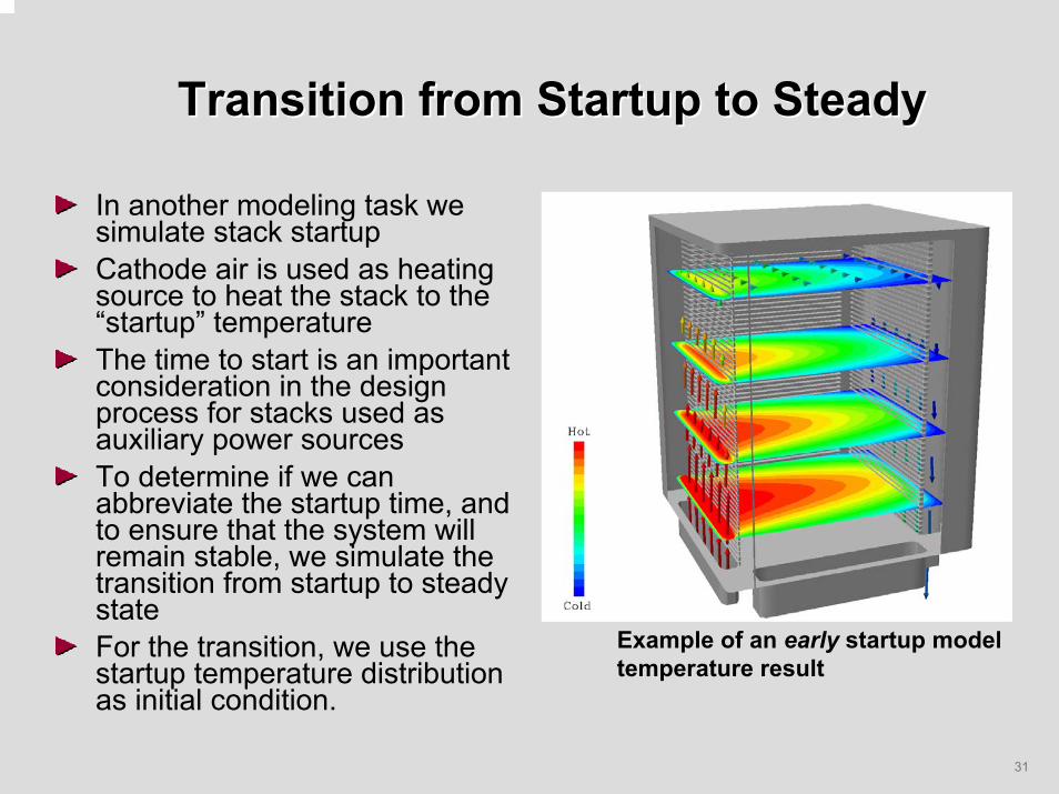
In another modeling task we simulate stack startupCathode air is used as heating source to heat the stack to the “startup” temperatureThe time to start is an important consideration in the design process for stacks used as auxiliary power sourcesTo determine if we can abbreviate the startup time, and to ensure that the system will remain stable, we simulate the transition from startup to steady stateFor the transition, we use the startup temperature distribution as initial condition.
Example of an early startup modeltemperature result

32
Transition from Startup to SteadyTransition from Startup to SteadyTransition from Startup to Steady
Run model fully transient from ambient – or – use initial temperature field from the end of a startup simulationIf restarted using an initial temperature field from a separate model, restart using the SMAP optionRun STAR-CD in transient modeUse artificially low specific heat – okay for preliminary test case to check problem stability, etc.Use correct properties for final, more accurate transient
“Startup” TemperatureDistribution(2% of transition time)
100% “Steady” TemperatureDistribution
Run ModelIn TransientMode
20%
40%

33
Multiple-Cell Stack Model MultipleMultiple--Cell Stack Model Cell Stack Model
Insulatedcontainer
CirculatingAir in Gap
SOFC Stack
Multiple-cellStack modeldomain
Fuel/Air IN
Fuel/Air OUT
Model domain is the full stack geometryConvection and Gap Radiation heat transfer to/from perimeter walls of stack/container included in the calculationsConstant Inflow boundary flow rates with variable temperature to control to desired operating temperatureCell voltage adjusted such that stack current is satisfied –> stack voltage distribution resolved.

34
Methodology: Multiple-Cell Stack
Methodology: Methodology: MultipleMultiple--Cell StackCell Stack
Multiple-Cell stack model is an extension of the single-cell stack calculationAdditional loop adjusts cell voltages such that stack current is satisfiedIn present implementation, the domain is decomposed to one cell per processor (using “sets”)
Simplifies “bookkeeping” and summation of scalars over each cell
Convergence criteria remains the equilibrium of the combustion and shift reactions
Sum over cell area (cpu) => Cell Current
Cell Current = Stack Current?
Yes No
Adjust CellVoltage

35
Multiple-Cell Stack Model & ResultsMultipleMultiple--Cell Stack Model & ResultsCell Stack Model & Results
Temperature ( C)
Average cell temperatures increase with height in stack (away from inflowing gas source).Cell temperature difference is maximum low in stack near cooler source gases

36
Multiple Cell Stack ModelsMultiple Cell Stack ModelsMultiple Cell Stack Models
The Multiple-Cell model is an extension of the single-cell stack to a “full stack” modelWall boundary conditions at stack ends remove cyclic assumptionCalculates voltage distribution and temperature distribution including stack end effectsDomain is decomposed one cell per processor (bring up model to demonstrate sets)Adjustments to posdat routine (istack, stacki)