three moment equation
DESCRIPTION
Three Moment EquationTRANSCRIPT
����������
���� ���������
����
������������
�������
610.05.2005 Dr. N. SureshDr. N. Suresh Department of Civil EngineeringNational Institute of Engineering,Mysore
• Definition of Beam
• Flexural Stiffness
• Types of Beams
• 3 - Moment Equation
Learning Outcomes
What is a beam?
A (usually) horizontal structural member that is subjected
to a load that tends to bend it
Examples of beams
• Engineering examples
– Floor joists and rafters
– I beams
• Biological examples
– Tree branches
– Vertebral column and neck
– Insect thorax/abdomen exoskeleton
Flexural stiffness (EI)
• Indicates how resistant a structure is to bending
• Depends on the material making up the structure and on its shape
(((( ))))(((( ))))area ofmoment Secondmodulus sYoung'====EI
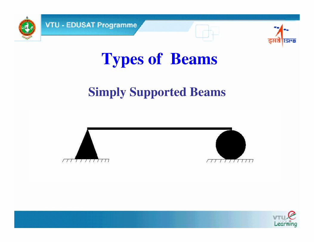
Simply Supported Beams
Types of Beams
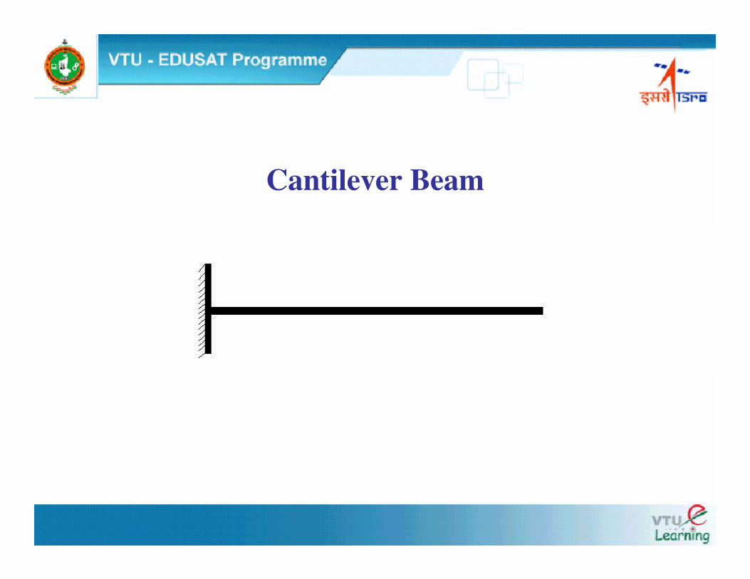
Cantilever Beam
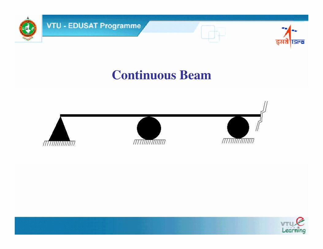
Continuous Beam
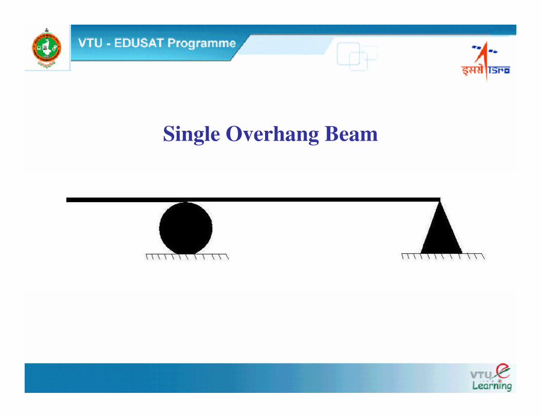
Single Overhang Beam
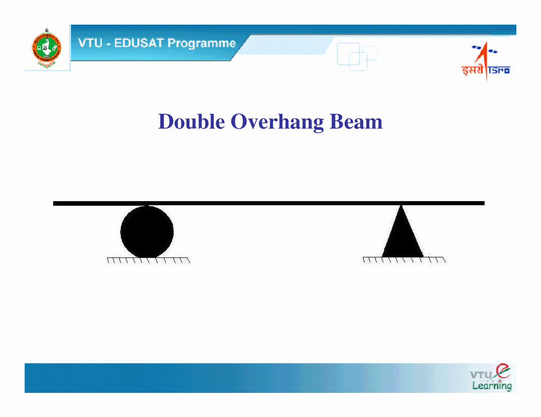
Double Overhang Beam
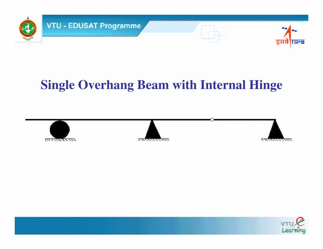
Single Overhang Beam with Internal Hinge
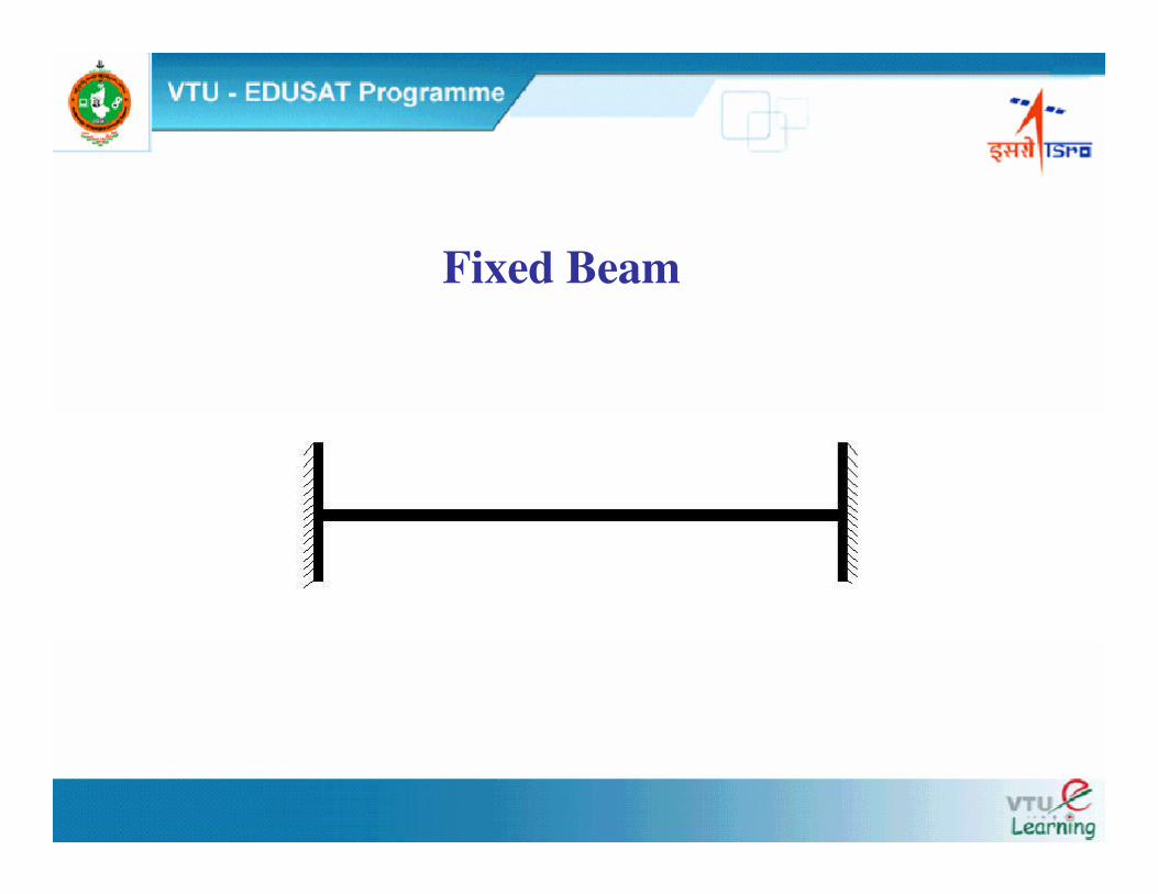
Fixed Beam
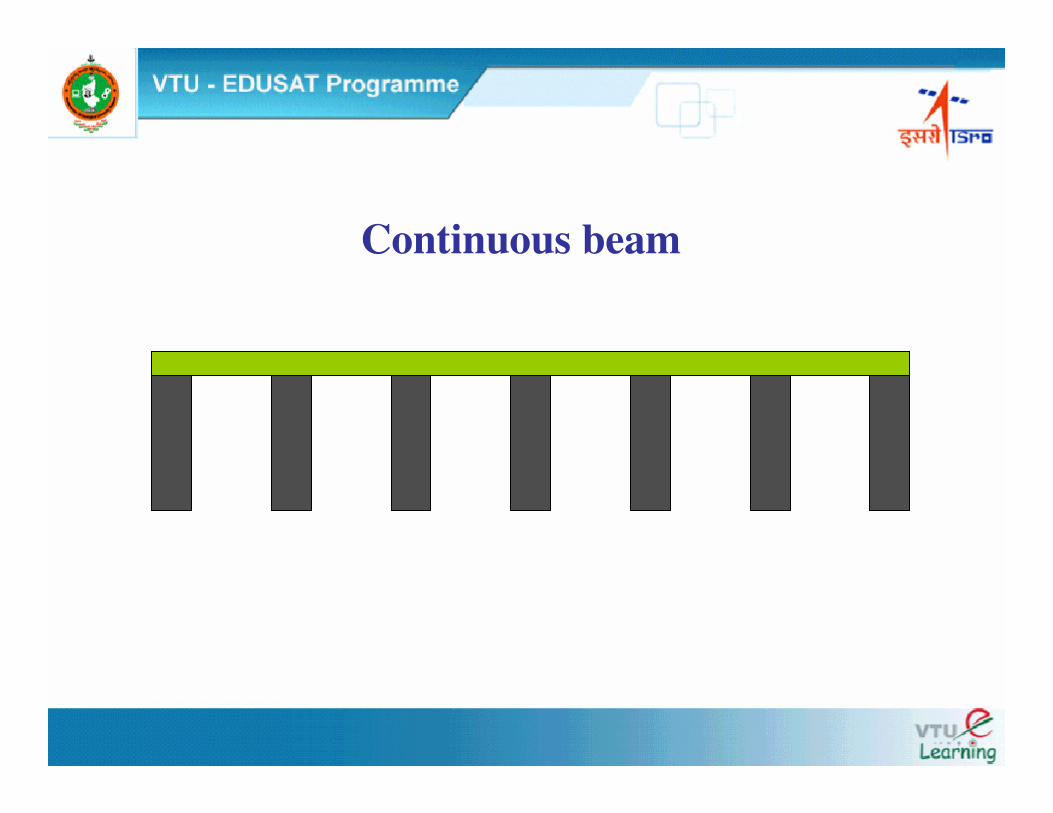
Continuous beam
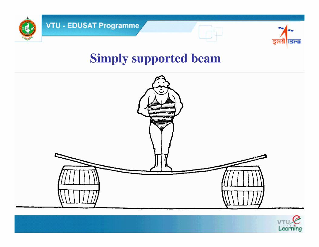
Simply supported beam
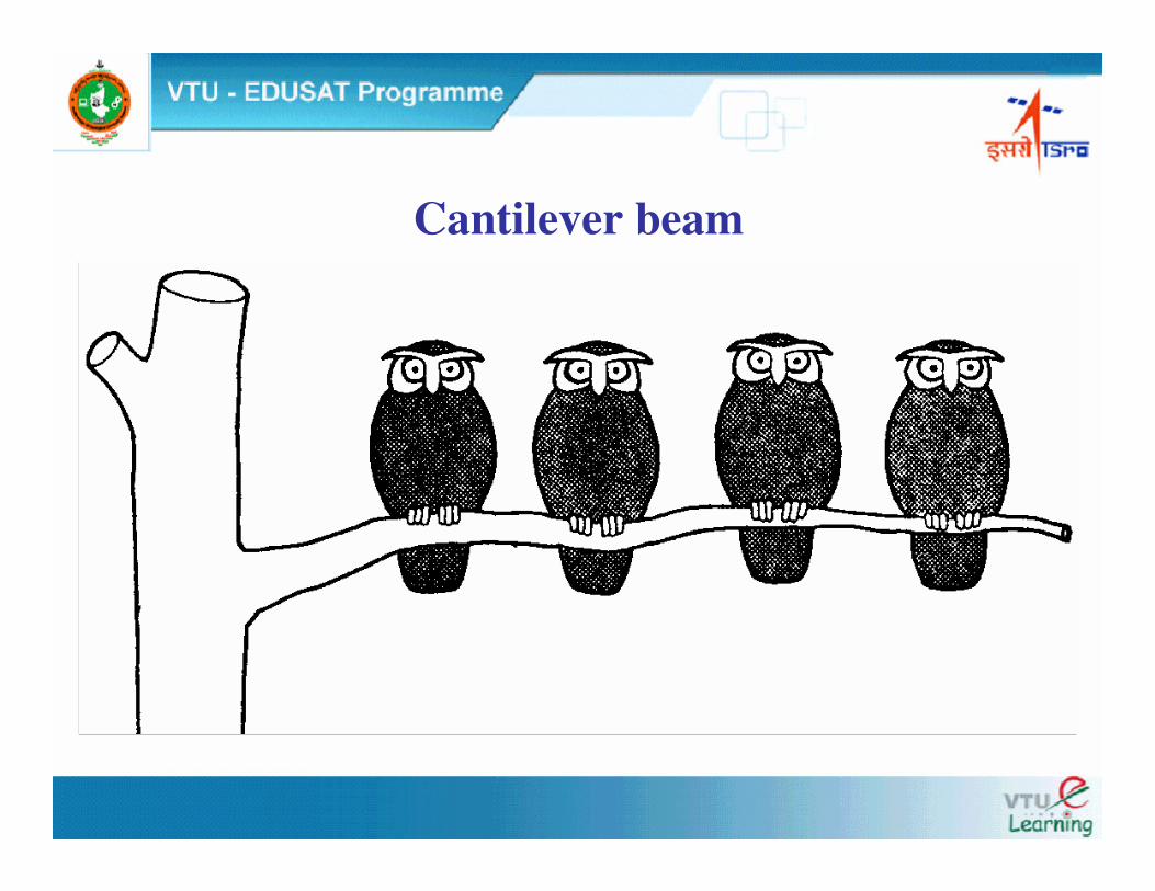
Cantilever beam
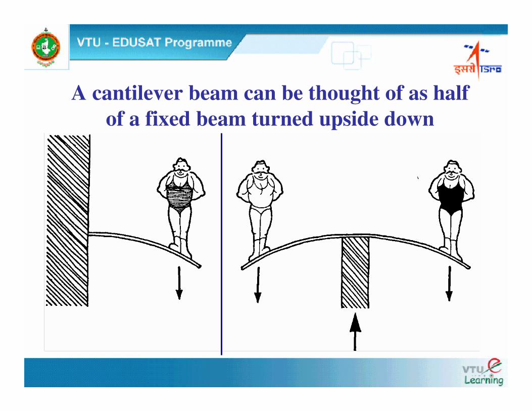
A cantilever beam can be thought of as half of a fixed beam turned upside down
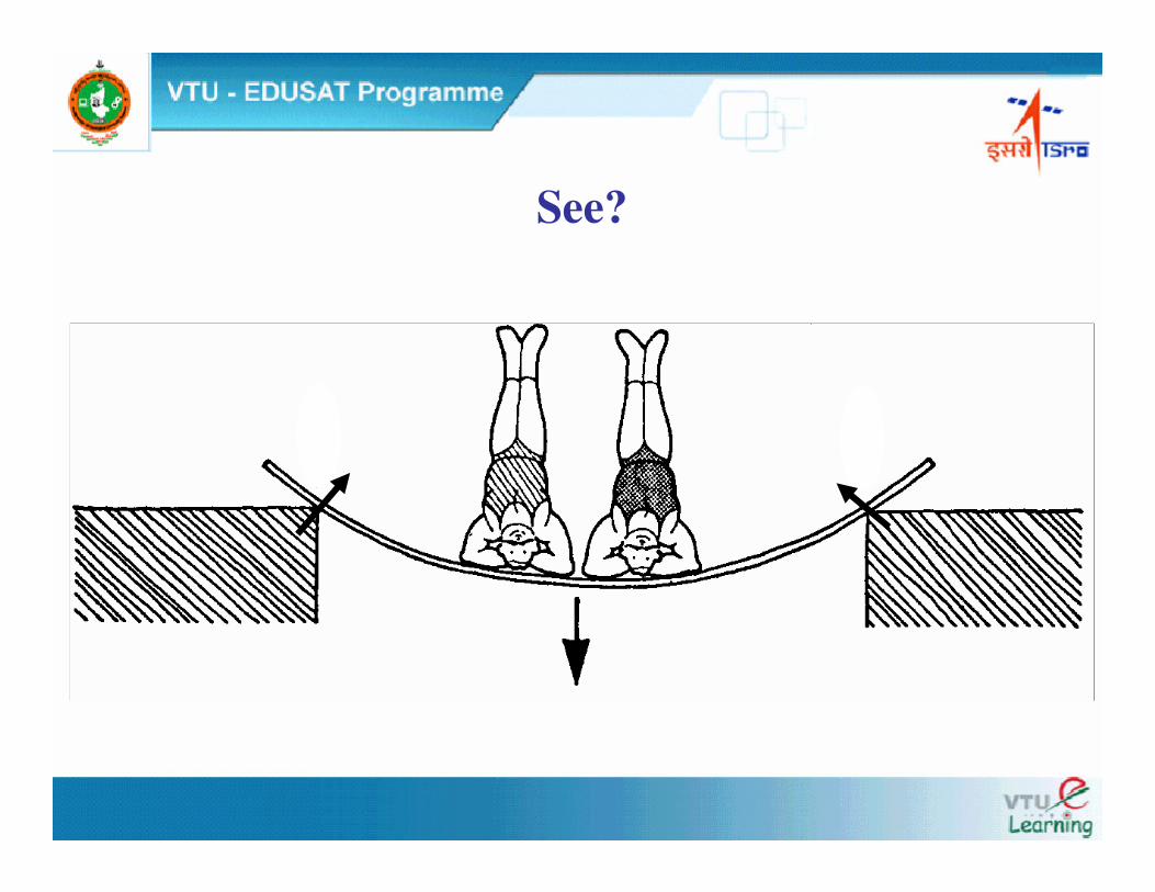
See?
ANALYSIS OF CONTINUOUS BEAMS (using 3-moment equation)
Stability of structure If the equilibrium and geometry of structure is maintained
under the action of forces than the structure is said to be stable.
External stability of the structure is provided by the reaction
at the supports. Internal stability is provided by proper design and
geometry of the member of the structure.
Statically determinate and indeterminate structures A structure whose reactions at the support can be determined
using available condition of equilibrium is called statically
determinate otherwise it is called statically indeterminate.
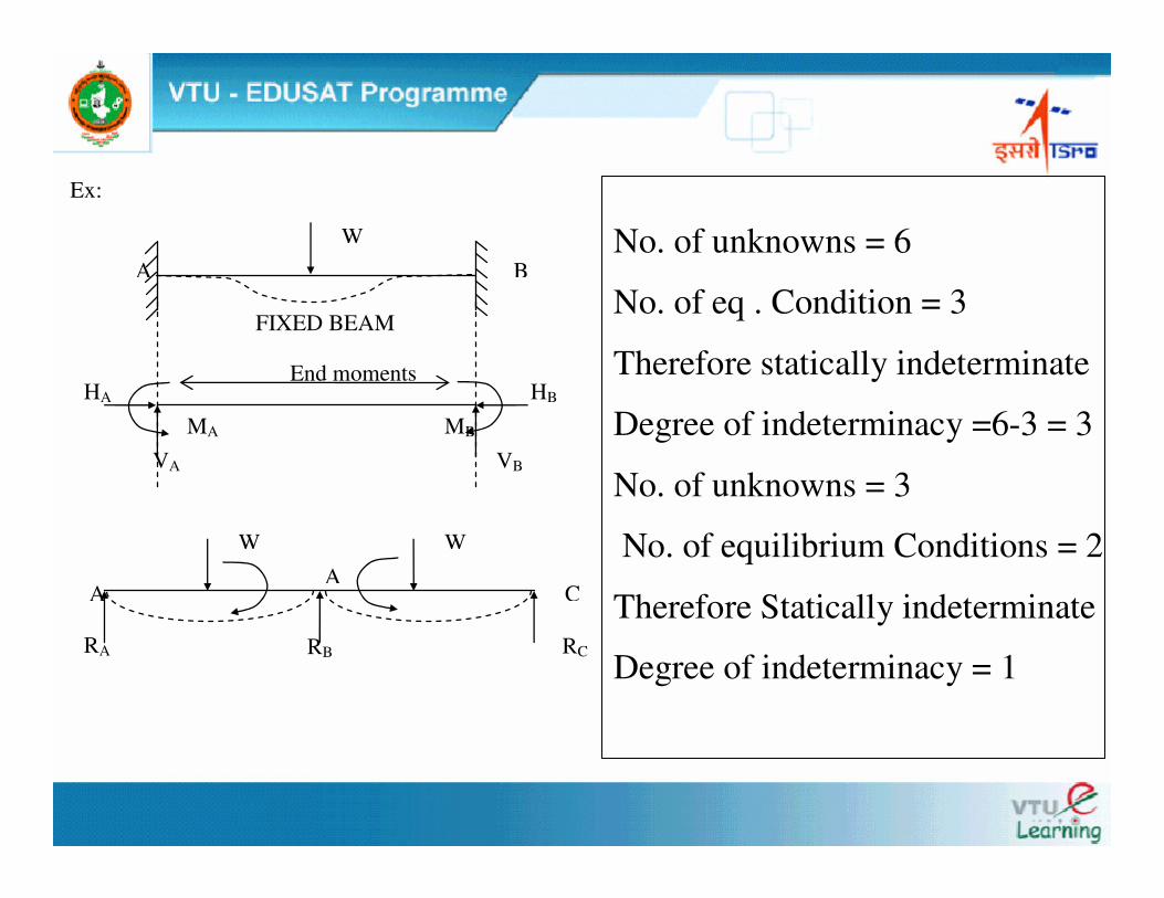
Ex:
W A B
HA HB
VA VB
MA MB
End moments
FIXED BEAM
W W
A
RA
RB
A C
RC
No. of unknowns = 6
No. of eq . Condition = 3
Therefore statically indeterminate
Degree of indeterminacy =6-3 = 3
No. of unknowns = 3
No. of equilibrium Conditions = 2
Therefore Statically indeterminate
Degree of indeterminacy = 1
Advantages of fixed ends or fixed supports 1. Slope at the ends is zero.
2. Fixed beams are stiffer, stronger and more stable than SSB.
3. In case of fixed beams, fixed end moments will reduce the
BM in each section.
4. The maximum deflection is reduced.
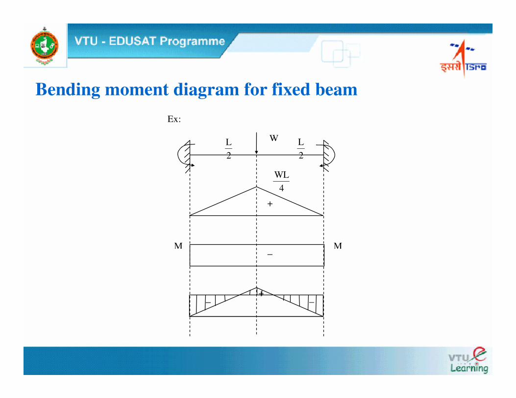
Bending moment diagram for fixed beam Ex:
W
4WL
2L
2L
+
−
− − +
M M
Continuous beams Beams placed on more than 2 supports are called
continuous beams. Continuous beams are used when the
span of the beam is very large, deflection under each rigid
support will be equal zero.
BMD for Continuous beams BMD for continuous beams can be obtained by
superimposing the fixed end moments diagram over the
free bending moment diagram.
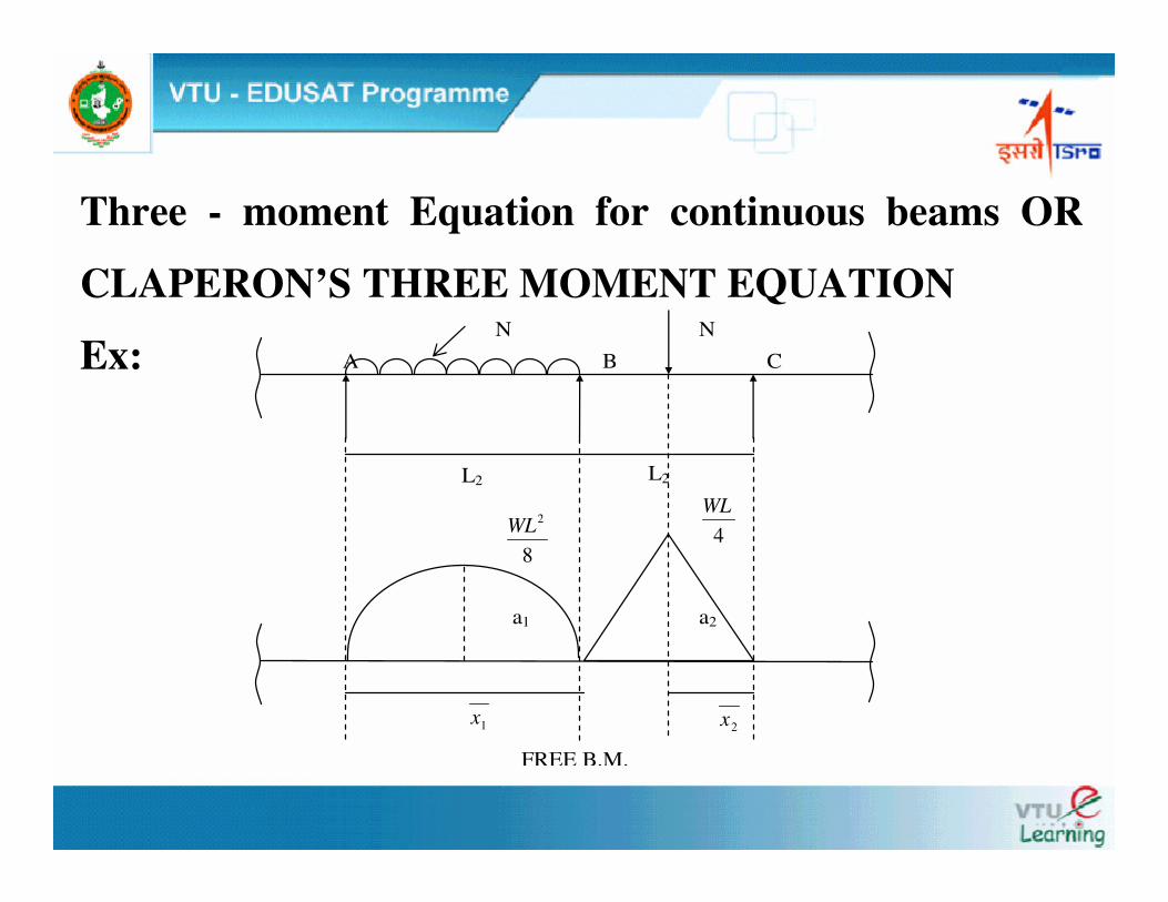
Three - moment Equation for continuous beams OR
CLAPERON’S THREE MOMENT EQUATION
Ex:
FREE B.M.
1x
a1 a2
8
2WL
L2 L2
A B C
N N
4WL
2x
������������
����������������
����++++������������
����������������
����++++++++��������
����
����������������
����
22
2C
22
2
11
1B
11
1A IE
LMIE
LIE
LM2IE
LM
��������
����
���� δδδδ−−−−δδδδ++++δδδδ−−−−δδδδ−−−−−−−−−−−−====2
BC
1
BA
222
22
111
11
LL6
LIExa6
LIExa6
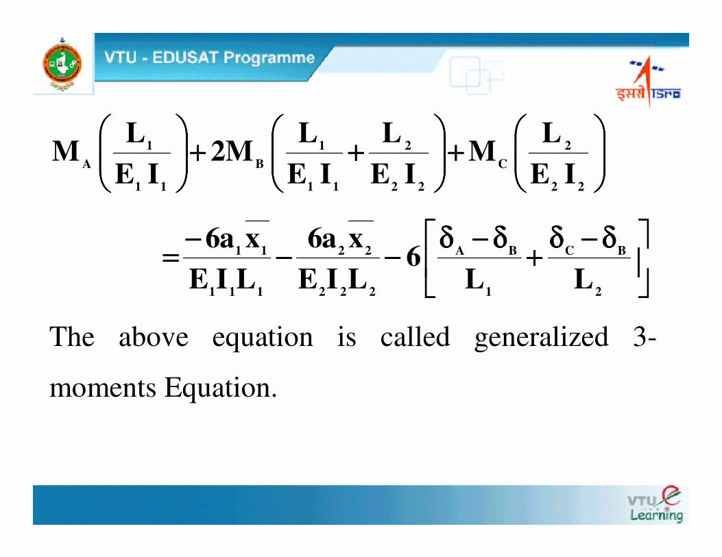
The above equation is called generalized 3-
moments Equation.
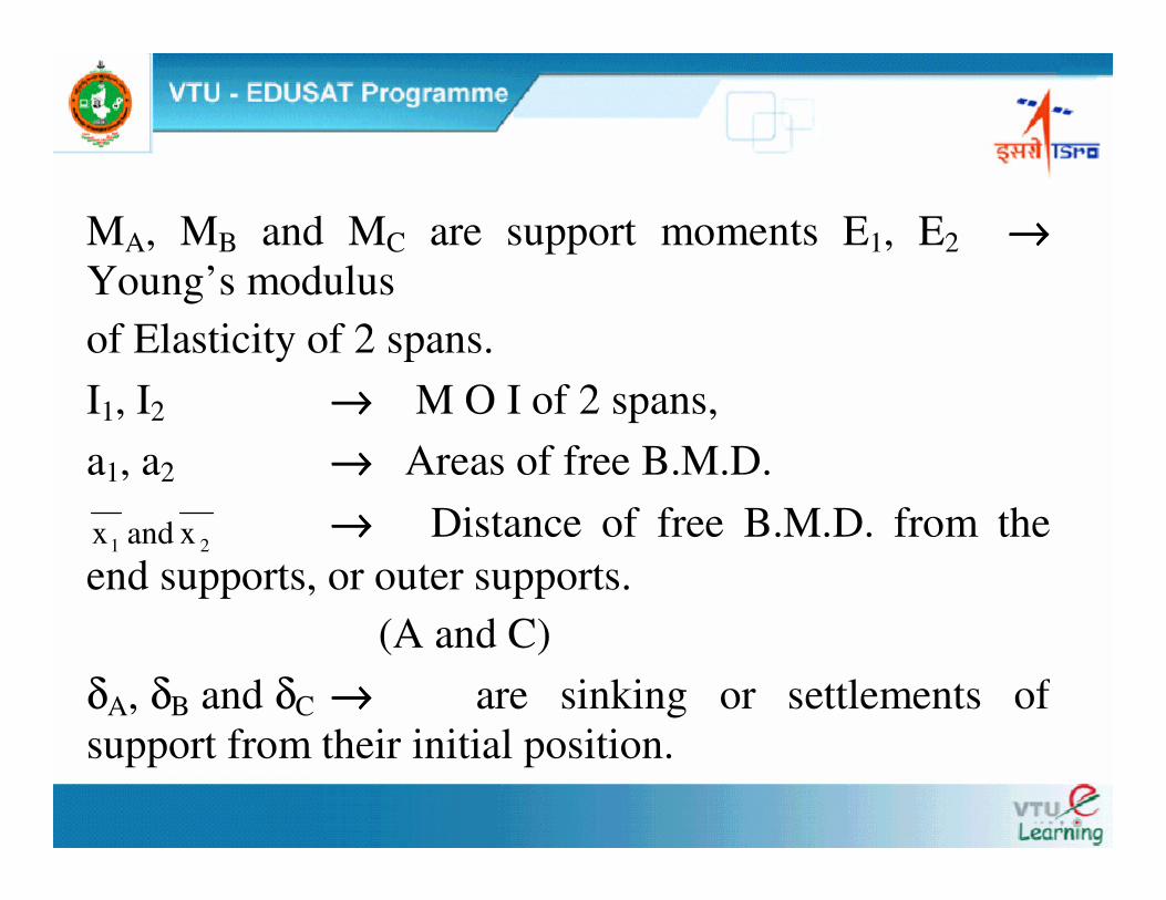
MA, MB and MC are support moments E1, E2 →→→→Young’s modulus of Elasticity of 2 spans. I1, I2 →→→→ M O I of 2 spans, a1, a2 →→→→ Areas of free B.M.D.
21 xandx →→→→ Distance of free B.M.D. from the end supports, or outer supports. (A and C) δA, δB and δC →→→→ are sinking or settlements of support from their initial position.
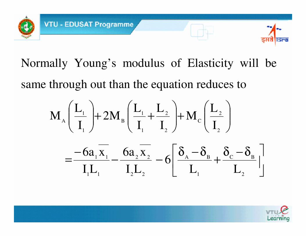
Normally Young’s modulus of Elasticity will be
same through out than the equation reduces to
���
����
�+���
����
�++��
�
����
�
2
2C
2
2
1
1B
1
1A I
LM
IL
IL
M2I
LM
��
�
� δ−δ+δ−δ−−−=2
BC
1
BA
22
22
11
11
LL6
LIxa6
LIxa6
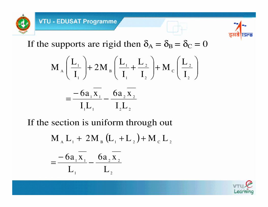
If the supports are rigid then δA = δB = δC = 0
���
����
�+���
����
�++��
�
����
�
2
2C
2
2
1
1B
1
1A I
LM
IL
IL
M2I
LM
22
22
11
11
LIxa6
LIxa6 −−=
If the section is uniform through out
( ) 2C21B1A LMLLM2LM +++
2
22
1
11
Lxa6
Lxa6 −−=
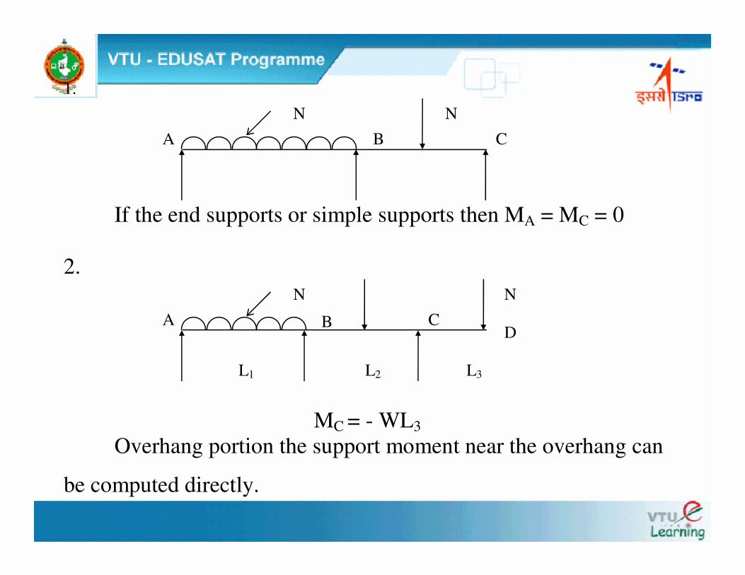
1.
If the end supports or simple supports then MA = MC = 0
2.
MC = - WL3
Overhang portion the support moment near the overhang can
be computed directly.
A B C
N N
D
L1 L2 L3
A B C
N N
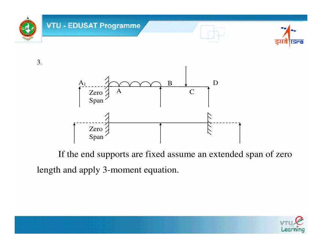
3.
If the end supports are fixed assume an extended span of zero
length and apply 3-moment equation.
Zero Span
A
B
C
A1 D
Zero Span
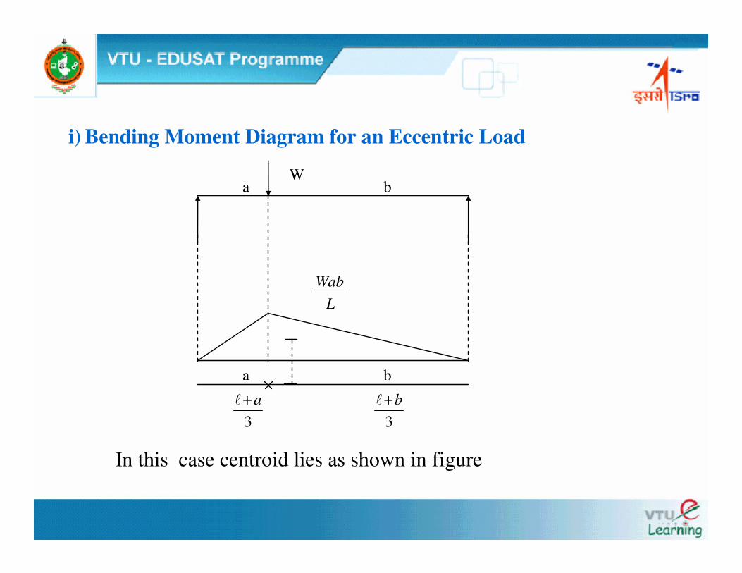
i) Bending Moment Diagram for an Eccentric Load
In this case centroid lies as shown in figure
a b W
LWab
a b
3a+�
3
b+�

ii) Bending Moment Diagram for Two Load at equidistant
a b
Wa Wa
2L
x =
L