three phase induction motor unit 4 1. introduction a poly phase induction motor consists of two...
TRANSCRIPT

1
Three Phase Induction Motor
Unit 4
2
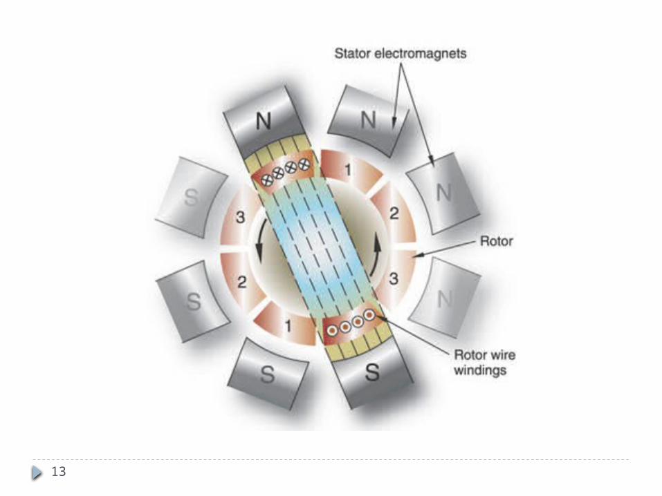
Introduction A poly phase induction motor consists of two major parts,
the stator and rotor When stator is excited with a.c voltage, rotating field is set
up This field produces an EMF in the rotor winding by mutual
induction principle, which in turn circulates current when the rotor is short circuited
This current interacts with the field produced by the stator winding, thereby producing torque which is responsible for the rotation of rotor.
3
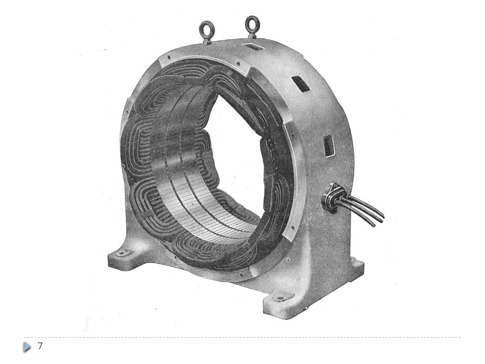
Construction Stator : Consists of core and winding . It is of cylindrical in structure , made of laminated sheet metal,
build up of laminations. Laminations are of thickness 0.35mm to 0.5mm Stator core internal diameter and length are the main dimensions
of induction motor
Rotor: Types: Squirrel Cage and Wound Rotor Squirrel cage rotors, consists of uninsulated bars of aluminium or
copper that are joined together at both ends by rings of similar conducting material
Rotor core is made up of laminated sheet of steel with thickness of 0.5 mm
4
Construction Aluminium bars and endrings are cased directly over the
rotor core When copper bars are employed , rotor bar are inserted on
the slots from the end of the rotor and end rings are joined to them by bracing
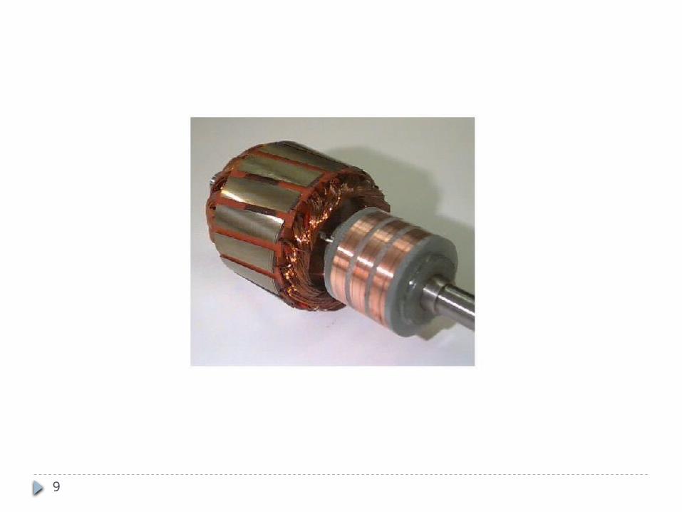
Wound rotor – consists of core, winding, sliprings and brushes.
Rotor core is made of laminations and it carries a three phase winding
One end of each phase are connected to form a star point Other end of each phase are connected to three slip rings

5
Slip rings are mounted on the rotor shaft and they are insulated from the rotor and from each other
Carbon brushes are mounted over the slip rings , facilitate the connection from rotor winding to the external resistances
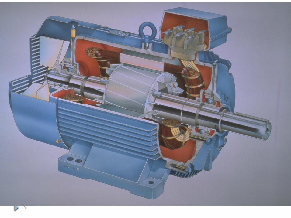
Construction
6
Construction
7

8
9

10

11

12
13

14

15
Advantages of Squirrel Cage Rotor over Wound Rotors i. No slip rings, brushes, short circuiting devices are
required
ii. Higher efficiency
iii. Cheaper and rugged in construction
iv. Has better space factor, shorter over hang, smaller copper loss
v. Has bare end rings, larger space for fans, thus cooling is better
vi. Better power factor, pull out torque and overload capacity

16
OUTPUT EQUATION
Out put equation for A.C machines is,
The rating of induction motor is given in Horse Power
cosφ .ηkW
Q
X10 .ac.BK 1.1 C where,
n LD .C Q kVA, Input3-
avwo
2o
.cosη φ0.746 X HP
Q

17
CHOICE OF SPECIFIC MAGNETIC LOADINGi. Power Factor: with higher values of Bav in the gap ,
results in large magnetizing current , giving low power factor. However in I.M Bg should be such that there is no saturation in any part of the magnetic circuit
ii. Iron loss: an increased in Bav result in increased in iron loss an decreased in efficiency
iii. Over load capcacity : with increase in Bav, flux per pole is large. Turns per phase and no of tursn becomes less. Reduction in leakage reactance. Thereby gives maximum output for same voltage. So machines has larger over load capcity

18
CHOICE OF SPECIFIC ELECTRIC LOADING i. Copper loss and temp rise: large value of ac , needs
greater amount of copper , results in higher copper losses and large temperature rise
ii. Voltage: for high voltage machines , less value of ac should be chosen, because it needs large space for insulation .
iii. Overload capacity: larger value of ac , results in large number of turns per phase. Which in turn increase the leakage reactance of the machine, reduces the overload capacity of the machine.

19
SPECIFIC MAGNETIC & ELECTRIC LOADING: Bav Specific magnetic loading:
Depends on power factor , iron loss and overload capacity. For 50Hz machine, Bav – 0.3 to 0.6T.
For machines used in cranes, rolling mills tec., need large overload capacity Bav- 0.65T
ac :Specific electric loading: Depends on copper loss, temp rise, voltage rating and
overload capacity. Varies between 5000 to 45000 ac/m.

20
MAIN DIMENSIONS Separation of D and L depends on the ratio of L/τ ( length
of core to pole pitch) L/τ = 1.5 to 2 for minimum cost L/τ = 1.0 to 1.25 for good power factor L/τ = 1.5 for good efficiency L/τ = 1 for over all design
Generally L/τ – 0.6 to 2; τ = √0.18L Diameter of the stator bore and hence diameter of rotor is
also limited by Va.
Va up to 60m/s can be employed
Stator - provided ventilating ducts (L ≥ 125mm) of 10mm width

21
STATOR WINDING In general double layer lap type winding with diamond
shaped coils is generally used for stators Small motors with a small no of slots and having large
no of turns per phase may use single layer mush windings
Three phase of the winding may be connected in either star or delta depending upon starting methods employed.
Squirrel cage induction motors - star delta starters
22
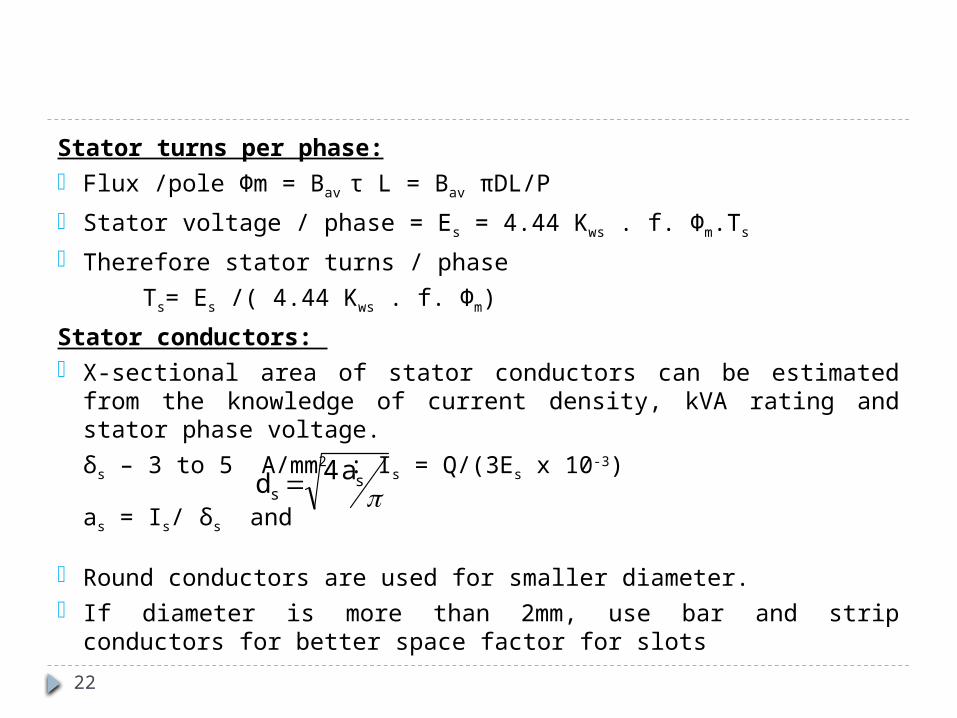
Stator turns per phase: Flux /pole Фm = Bav τ L = Bav πDL/P
Stator voltage / phase = Es = 4.44 Kws . f. Фm.Ts
Therefore stator turns / phase
Ts= Es /( 4.44 Kws . f. Фm)
Stator conductors: X-sectional area of stator conductors can be estimated from the
knowledge of current density, kVA rating and stator phase voltage.
δs – 3 to 5 A/mm2 : Is = Q/(3Es x 10-3)
as = Is/ δs and
Round conductors are used for smaller diameter. If diameter is more than 2mm, use bar and strip conductors for better
space factor for slots
a 4 d ss
23
STATOR CORE Made of laminations of thickness of 0.5mm Design of stator core involves shape of slots, no. of slots ,
dimensions of teeth and depth of slot
Shape of slot : Open and Semi-closed slots may be used When open slots are used, winding coils can be formed and
insulated completely before they are inserted in the slots. Easy for repair. Avoids excessive slot leakage
Semi-closed slots are usually preferred of I.M because Kg will be less, results in less magnetizing current, also results in low tooth pulsation loss and less noise operation
Tapered coils are used in semi closed slots
24
In small motors round conductors are used In large and medium size motors strip conductors are
preferred In both case tapered slot with parallel sided tooth
arrangement is preferred, because it gives maximum slot area for particular flux density.
Number of slots : Depends on tooth pulsation loss, leakage reactance ,
ventilation, magnetizing current , iron loss and cost. In general no. of slots should be chosen as an integral For open type slots, slot pitch at the gap – 15 to 25mm For semi closed slots, the slot pitch may be less than 15mm
STATOR CORE
25
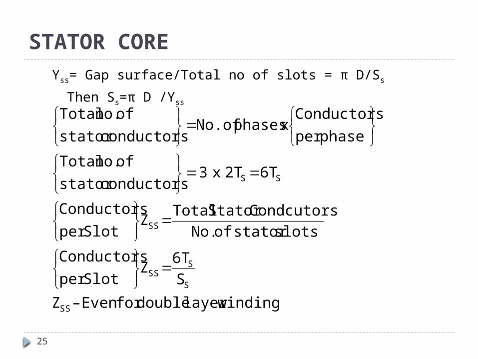
Yss= Gap surface/Total no of slots = π D/Ss
Then Ss=π D /Yss
winding layer double for Even –Z
S6T
ZSlot per
Conductors
slots stator of No.
Condcutors Stator Total Z
Slot per
Conductors
6T 2T x 3 conductors stator
of no. Total
phase per
Conductorsx phases No.of
conductors stator
of no. Total
SS
S
SSS
SS
SS
STATOR CORE
26
Area of stator slots : Once no. of conductors per slot has been obtained,
approximate area of the slot can be calculated Area of the slot = (Copper area/slot)/Space factor
= ZssX ag/Space factor Space factor - 0.25 to 0.4 High voltage machines have lower space factors owing to
large thickness of insulation. After obtaining the area of the slot, the dimensions of the
slot should be adjusted Tooth width and the slot width at gap surface should be
approx equal
STATOR CORE

27
The width of the slot should e so adjusted such that
Bt – 1.3 to 1.7 T.
In general ratio of slot depth / slot pitch- 3 to 6
Length of mean turn Lmts = 2L + 2.3τ + 0.24
Stator teeth: The dimensions of the slot determines the value of Bt.
High value of Bt is not desirable, as it leads to a higher iron loss and greater magnetizing MMF.
Bt should not exceed 1.7 T.
STATOR CORE

28
The minimum width of stator teeth is near the air gap surface or 1/3rd of height of the slots
A check for minimum tooth width using the above equation should be applied before finally deciding the dimensions of stator slot
i
S
mmints
tsiS
m
L PS
1.7
φ W
.W L PS
/pole area Total
tooth of Widthlength iron Net pole per
slots of No. /pole area Total
1.7φ
area/pole tooth Minimum
STATOR CORE

29
Depth of the stator core : Depends on flux density in the core,
BCS - 1.2 to 1.5 T
Flux passing through the stator core is half of the flux per pole.
)d 2(d D D core, stator of diameter Outside
L .2Bφ
d core, of Depth
(2) and (1) Equating
(2) d X L core stator the of Areaalso,
(1)2Bφ
core stator in density FluxCore through Flux
core stator the of Area
2φ
φ core, stator the in Flux
Therefore,
cssso
iCS
mCS
CSi
CS
m
mc
STATOR CORE
D
dss
Do
dcs
Cross Section of Stator Core

30
LENGTH OF THE AIR GAP
lg - decided by considering the following factors: Power factor Overload capacity Pulsation loss Unbalanced magnetic pull Cooling Noise
Power factor: MMF required to send the flux through the air gap is proportional
to the product of B and lg
Even with small B, MMF required for air gap is much more than that for the rest of the magnetic circuit.
lg – determines the magnetizing current drawn by the machine.
Magnetizing current inversely proportional to power factor

31
Overload capacity: lg affects the value of zig-zag leakage reactance which
forms a large part of total leakage reactance . If lg is larger, then zig-zag leakage flux will be less and so
leakage reactance will be less, results in increase in overload capacity
Pulsation loss: With larger length of air gap, the variation of reluctance due
to slotting is small. The tooth pulsation loss, which is produced due to
variation in reluctance of air gap, is reduced accordingly. Therefore, the pulsation loss is less with large air gaps.
LENGTH OF THE AIR GAP
32
Unbalanced magnetic pull If the lg is small, then even for small deflection or eccentricity of the
shaft would produce large irregularity in lg . It is responsible for the production of UMP, which has the tendency to
bend the shaft still more at a place where it is already bent resulting in fouling of rotor with stator.
If lg is large, a small eccentricity would not able to produce noticeable UMP.
Cooling: If lg is large, cylindrical surfaces of rotor and stator are separated by a
large distance. This would afford better facilities for cooling at the gap surfaces
especially when a fan is fitted for circulation of airNoise: The principle cause of noise in I.M is the variation of reluctance of the
path of the zig-zag leakage as small as possible, can be done by increasing lg.
LENGTH OF THE AIR GAP

33
Relations for length of air gapi. For small I.M , lg = 0.2 + 2√DL mm
ii. Alternate formula for small Induction Motors,
lg = (0.125 + 0.35 D + L + 0.015Va ) mm
iii. For general use, lg = (0.2 + D) mm
iv. For machines with journal bearings
lg = 1.6 √D – 0.25 mm
D,L and Va are in meters
D in mm lg in mm
0.15 0.35
0.20 0.50
0.25 0.60
0.30 0.70
0.45 1.30
0.55 1.80
0.65 2.50
0.80 4.00
34
DESIGN OF SQUIRREL CAGE INDUCTION ROTOR The squirrel cage rotor consists of laminated core, rotor
bars and end rings The rotor bars and end rings are made of Al or Cu lr is same as that of stator
Diameter of the rotor is slightly lesser than the stator to avoid mechanical friction between the stationary stator and rotating rotor
Rotor diameter Dr = Stator Bore(D) – 2lg

35
DESIGN OF ROTOR BARS AND SLOTS For a three phase machine , the rotor bar current is given by
the equation,
Rotor bar current Ib =(6Ts.Is)Kws cosФ/Sr
o.85(6Ts.Is)/Sr
Performance of an induction motor is greatly influenced by the resistance of the rotor
Higher rotor resistance has higher starting torque but lesser efficiency
Rotor resistance is the sum of resistance of the bars and the endrings
The cross section of the rotor bars and end rings are selected to meet both requirements of Tst as well as efficiency

36
Current density of the rotor bar,δb - 4 to 7 A/mm2
Area of each rotor bar, ab = Ib/ δb mm2
In case of squirrel cage motor the X-sectional area of bars will take the shape of the slot and insulation is not used between bars and rotor core.
The rotor slots for squirrel cage rotor may be either closed or semi closed types.
Advantages of closed slots: Low reluctance Less magnetizing current Quieter operation Large leakage reactance and so starting current is limited
Disadvantage of closed slots: Reduced overload capacity
DESIGN OF ROTOR BARS AND SLOTS

37
Rules for Selecting Rotor Slots:i. No. of stator slots should never be equal to rotor slots.
Sr is 15% less than Ss
ii. The difference (Ss-Sr) should not be equal to ± P, ±2P or ± 5P to avoid synchronous steps
iii. The difference (Ss-Sr) should not be equal to ±3 P to avoid magnetic locking
iv. The difference (Ss-Sr) should not be equal to ± 1, ±2 ,± (p ± 1) or ,± (p ± 2) to avoid noise and vibrations
DESIGN OF ROTOR BARS AND SLOTS

38
DESIGN OF END RINGS The distribution of current in the bars and end rings of a
squirrel cage motor is complicated It can be shown that if flux distribution is sinusoidal then the bar
current and end ring current will also be sinusoidal Max. value of end ring current
However , current is not maximum in all the bars under one pole at the same time but varies according to sine law
Hence the max. value of the current in the end ring is the average of the current of half the bars under one pole
b(max)r
e(max)
I2pS
Bar per Current X 2
Pole per Bars I

39
Maximum value of end ring current,
Current density of the end ring δe - 4 to 7 A/mm2
Ae= Ie/ δe mm2
also Ae = Depth of end ring X Thickness of end rings = de X te
pπSI2
I2 π2
2pS
I π2
2pS
I2
pole per Bars I
rbb
r
b(max)r
b(ave)e(max)
DESIGN OF END RINGS