three phase motor alogue indian...
TRANSCRIPT
Motors | Energy | Automation | Coatings
W21Three Phase Motor
TECHNICAL CATALOGUE
INDIAN MARKET
www.weg.net
W21 Three Phase Motor2
W21
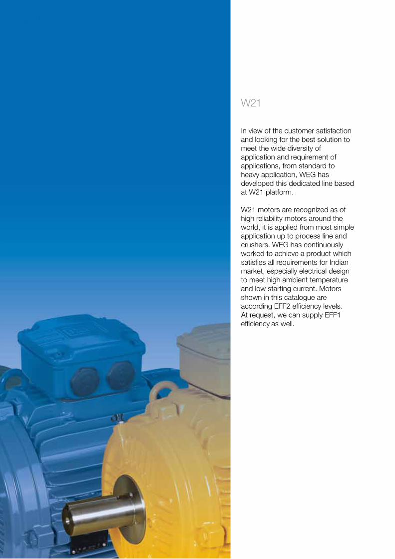
In view of the customer satisfaction and looking for the best solution to meet the wide diversity of application and requirement of applications, from standard to heavy application, WEG has developed this dedicated line based at W21 platform.
W21 motors are recognized as of high reliability motors around the world, it is applied from most simple application up to process line and crushers. WEG has continuously worked to achieve a product which satisfies all requirements for Indian market, especially electrical design to meet high ambient temperature and low starting current. Motors shown in this catalogue are according EFF2 efficiency levels. At request, we can supply EFF1 efficiency as well.
www.weg.net
W21 Three Phase Motor 3
Table of Contents
1. General information .......................................................................................................................... 42. Standards ........................................................................................................................................ 43. Construction details ......................................................................................................................... 5 3.1 Frame / Endshields..................................................................................................................... 5 3.2 Grounding .................................................................................................................................. 5 3.3 Fan cover ................................................................................................................................... 5 3.4 Terminal box .............................................................................................................................. 5 3.4.1 Connection leads .................................................................................................................. 6 3.4.2 Connection of accessories ................................................................................................... 6 3.5 Nameplate ................................................................................................................................. 74. Cooling system / Noise level / Vibration level .................................................................................... 8 4.1 Cooling system / Noise level ....................................................................................................... 8 4.2 Vibration level ............................................................................................................................. 85. Shaft / Bearings / Thrusts ................................................................................................................ 9 5.1 Shaft .......................................................................................................................................... 9 5.2 Bearings .................................................................................................................................... 9 5.2.1 Bearing locking .................................................................................................................... 10 5.2.2 Bearing monitoring .............................................................................................................. 126. Mounting ........................................................................................................................................ 137. Degree of protection / Painting ........................................................................................................ 14 7.1 Degree of protection .................................................................................................................. 14 7.2 Painting ..................................................................................................................................... 14 7.2.1 Tropicalized painting ............................................................................................................. 148. Ambient & Insulation ....................................................................................................................... 159. Variable frequency drive application ................................................................................................ 16 9.1 Considerations about rated voltage ........................................................................................... 16 9.2 Torque restrictions on variable frequency drive applications ...................................................... 16 9.3 Restrictions about current flowing through the bearings ............................................................ 17 9.4 Forced ventilation kit ................................................................................................................. 1710. Tolerances for electrical data ......................................................................................................... 1811. Construction features .................................................................................................................... 1912. Optional features ........................................................................................................................... 2213. Electrical data ............................................................................................................................... 2614. Mechanical data ........................................................................................................................... 30 14.1 Mechanical data - Flanges ....................................................................................................... 31 14.1.1 “C” Flange .......................................................................................................................... 31 14.1.2 “FF” Flange ........................................................................................................................ 3215. Terminal box drawings .................................................................................................................. 3316. Features and benefits ................................................................................................................... 34
www.weg.net
W21 Three Phase Motor4
1. General information
2. Standards
The WEG W21 series motors are designed to meet specific requirements of some markets. These motors are available in frame sizes IEC 63 to 355M/L and are suitable for operation up to ambient temperature of 50 ºC with temperature rise restricted to class B (70 K). They are suitable for 415 V, 3 Phase, 50 Hz Supply and are also suitable to operate at tolerances of +- 10% in voltage, +- 5% in frequency and +- 10% combined variation of both voltage and frequency. Additionally, they can operate continuously with a 2% unbalance on power supply voltage.
These motors are supplied with six terminals and are suitable for DOL starting and Star-Delta (except for output ratings below 1.5 kW, which are supplied with internally star-connected windings with three terminals in the terminal box). The minimum Pull Out torque is 210% of the rated torque and the starting current corresponds to 6 times the rated current value. All performance parameters are at rated supply conditions and are subject to tolerance as per IEC standard.
The W21 motors are supplied as standard with EFF2 efficiency level, as per table defined by CEMEP, and the efficiency levels are tested in conformance with IEC 60032-2 requirements.
The W21 motors meet the requirement and regulations of updated version of the following standards:
IEC60034-1 Rotating electrical machines – Part 1: Rating and performance.IEC60034-2 Rotating electrical machines – Part 2: Standard methods for determining losses and efficiency from tests (excluding machines for traction vehicles).IEC60034-5 Rotating electrical machines – Part 5: Degrees of protection provided by the integral .design of rotating electrical machines (IP code) – classification.IEC60034-6 Rotating electrical machines – Part 6: Methods of cooling (IC code).IEC60034-7 Rotating electrical machines – Part 7: Classification of types of enclosures and mounting arrangements (IM code).IEC60034-8 Rotating electrical machines – Part 8: Terminal markings and direction of rotation.IEC60034-9 Rotating electrical machines – Part 9: Noise limits.IEC60034-11-1 Rotating electrical machines – Part 11-1: Thermal protection.IEC60034-12 Rotating electrical machines – Part 12: Starting performance of single-speed three-phase cage induction motors.IEC60034-14 Rotating electrical machines – Part 14: Mechanical vibration of certain machines – Limits of vibration.IEC60072-1 Dimensions and output series for rotating electrical machines – Part 1: Frame numbers 56 to 400 and flange numbers 55 to 1080.
www.weg.net
W21 Three Phase Motor 5
3. Construction details
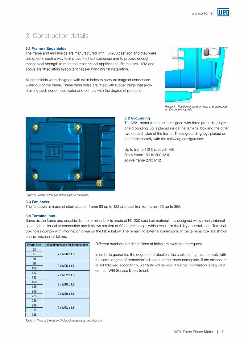
The frame and endshields are manufactured with FC-200 cast iron and they were designed in such a way to improve the heat exchange and to provide enough mechanical strength to meet the most critical applications. Frame size 112M and above are fitted lifting eyebolts for easier handling on installation.
All endshields were designed with drain holes to allow drainage of condensed water out of the frame. These drain holes are fitted with rubber plugs that allow draining such condensed water and comply with the degree of protection.
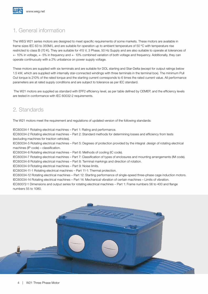
Same as the frame and endshields, the terminal box is made of FC-200 cast iron material. It is designed withy plenty internal space for easier cable connection and it allows rotation at 90 degrees steps which results in flexibility on installation. Terminal box holes comply with information given on the table below. The remaining external dimensions of the terminal box are shown on the mechanical tables.
Different number and dimensions of holes are available on request.
In order to guarantee the degree of protection, the cables entry must comply with the same degree of protection indicated on the motor nameplate. If the procedure is not followed accordingly, warranty will be void. If further information is required, contact WEI Service Department.
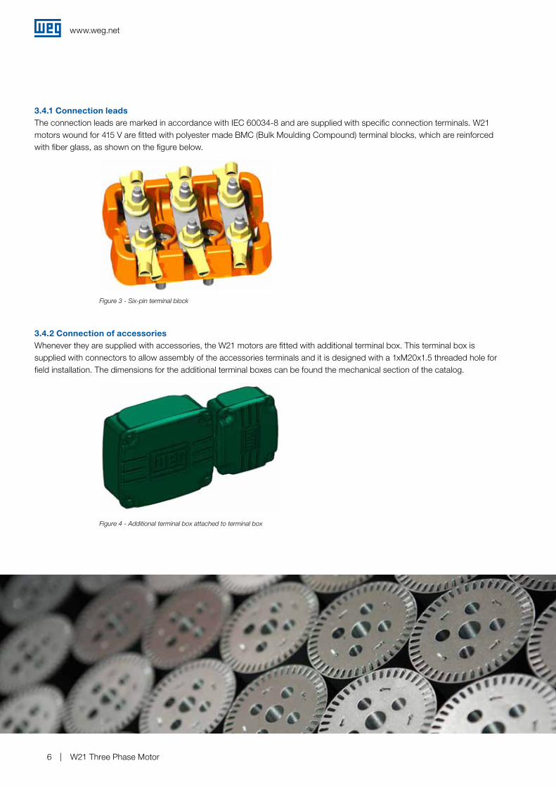
The W21 motor frames are designed with three grounding lugs: one grounding lug is placed inside the terminal box and the other two on each side of the frame. These grounding lugs placed on the frame comply with the following configuration:
Up to frame 112 (included): M6From frame 160 to 200: M10Above frame 200: M12
The fan cover is made of steel plate for frame 63 up to 132 and cast iron for frame 160 up to 355.
3.1 Frame / Endshields
3.4 Terminal box
3.2 Grounding
3.3 Fan cover
Figure 1 - Position of the drain hole and drain plug on the drive endshield
Figure 2 - Detail of the grounding lugs on the frame
Frame size Holes dimensions for terminal box63
2 x M20 x 1.5718090
2 x M25 x 1.5100112
2 x M32 x 1.5132160
2 x M40 x 1.5180200
2 x M50 x 1.5225250
2 x M63 x 1.5280315355
Table 1 - Type of thread and holes dimensions for terminal box
www.weg.net
W21 Three Phase Motor6
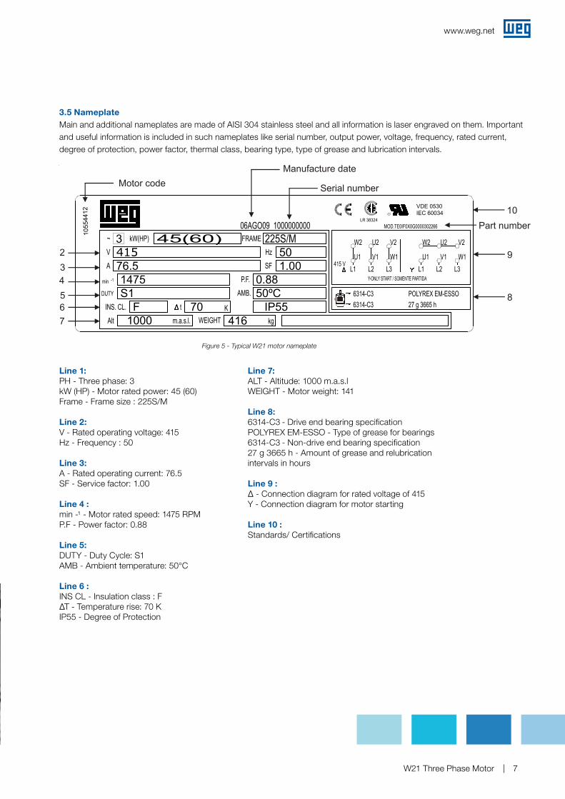
3.4.1 Connection leadsThe connection leads are marked in accordance with IEC 60034-8 and are supplied with specific connection terminals. W21 motors wound for 415 V are fitted with polyester made BMC (Bulk Moulding Compound) terminal blocks, which are reinforced with fiber glass, as shown on the figure below.
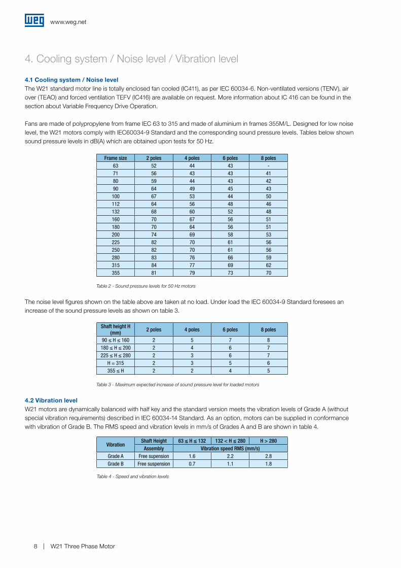
3.4.2 Connection of accessoriesWhenever they are supplied with accessories, the W21 motors are fitted with additional terminal box. This terminal box is supplied with connectors to allow assembly of the accessories terminals and it is designed with a 1xM20x1.5 threaded hole for field installation. The dimensions for the additional terminal boxes can be found the mechanical section of the catalog.
Figure 3 - Six-pin terminal block
Figure 4 - Additional terminal box attached to terminal box
www.weg.net
W21 Three Phase Motor 7
3.5 NameplateMain and additional nameplates are made of AISI 304 stainless steel and all information is laser engraved on them. Important and useful information is included in such nameplates like serial number, output power, voltage, frequency, rated current, degree of protection, power factor, thermal class, bearing type, type of grease and lubrication intervals.
Line 1: PH - Three phase: 3 kW (HP) - Motor rated power: 45 (60)Frame - Frame size : 225S/M
Line 2: V - Rated operating voltage: 415Hz - Frequency : 50
Line 3: A - Rated operating current: 76.5SF - Service factor: 1.00
Line 4 :min -¹ - Motor rated speed: 1475 RPMP.F - Power factor: 0.88
Line 5: DUTY - Duty Cycle: S1AMB - Ambient temperature: 50°C
Line 6 :INS CL - Insulation class : FΔT - Temperature rise: 70 KIP55 - Degree of Protection
Figure 5 - Typical W21 motor nameplate
3
VDE 0530IEC 60034
76.5415
F1000
S11475
70 IP55416
50ºC0.88
1.00502
34567
Line 7: ALT - Altitude: 1000 m.a.s.lWEIGHT - Motor weight: 141
Line 8:6314-C3 - Drive end bearing specificationPOLYREX EM-ESSO - Type of grease for bearings6314-C3 - Non-drive end bearing specification27 g 3665 h - Amount of grease and relubrication intervals in hours
Line 9 :∆ - Connection diagram for rated voltage of 415Y - Connection diagram for motor starting
Line 10 :Standards/ Certifications
www.weg.net
W21 Three Phase Motor8
4. Cooling system / Noise level / Vibration level
4.1 Cooling system / Noise levelThe W21 standard motor line is totally enclosed fan cooled (IC411), as per IEC 60034-6. Non-ventilated versions (TENV), air over (TEAO) and forced ventilation TEFV (IC416) are available on request. More information about IC 416 can be found in the section about Variable Frequency Drive Operation.
Fans are made of polypropylene from frame IEC 63 to 315 and made of aluminium in frames 355M/L. Designed for low noise level, the W21 motors comply with IEC60034-9 Standard and the corresponding sound pressure levels. Tables below shown sound pressure levels in dB(A) which are obtained upon tests for 50 Hz.
4.2 Vibration levelW21 motors are dynamically balanced with half key and the standard version meets the vibration levels of Grade A (without special vibration requirements) described in IEC 60034-14 Standard. As an option, motors can be supplied in conformance with vibration of Grade B. The RMS speed and vibration levels in mm/s of Grades A and B are shown in table 4.
The noise level figures shown on the table above are taken at no load. Under load the IEC 60034-9 Standard foresees an increase of the sound pressure levels as shown on table 3.
Frame size 2 poles 4 poles 6 poles 8 poles63 52 44 43 -71 56 43 43 4180 59 44 43 4290 64 49 45 43100 67 53 44 50112 64 56 48 46132 68 60 52 48160 70 67 56 51180 70 64 56 51200 74 69 58 53225 82 70 61 56250 82 70 61 56280 83 76 66 59315 84 77 69 62355 81 79 73 70
Table 2 - Sound pressure levels for 50 Hz motors
Table 3 - Maximum expected increase of sound pressure level for loaded motors
Table 4 - Speed and vibration levels
Shaft height H (mm)
2 poles 4 poles 6 poles 8 poles
90 ≤ H ≤ 160 2 5 7 8180 ≤ H ≤ 200 2 4 6 7225 ≤ H ≤ 280 2 3 6 7
H = 315 2 3 5 6355 ≤ H 2 2 4 5
VibrationShaft Height 63 ≤ H ≤ 132 132 < H ≤ 280 H > 280
Assembly Vibration speed RMS (mm/s)Grade A Free supension 1.6 2.2 2.8Grade B Free suspension 0.7 1.1 1.8
www.weg.net
W21 Three Phase Motor 9
5. Shaft / Bearings / Thrusts
5.1 ShaftThe shaft of W21 standard motors is made of AISI 1040/45 steel in frames IEC 63 to 315S/M and in AISI 4140 steel in frames 315B and 355M/L. When supplied with roller bearings as an option, shaft material must be AISI 4140.Since they are fitted with AISI 4140 steel shaft in frames 315B and 355M/L, W21 motors can be supplied with roller bearings, so they will be suitable for heavy duty applications such as pulley and belt applications. Further information about maximum allowable radial and axial loads on shaft end is given in tables 6, 7 and 8.
Important: To modify bearings from ball into roller, drive end and non-drive end bearing caps (internal and external) need to be replaced since non-drive end bearing remains locked. If further information is required, contact WEI Service Department.
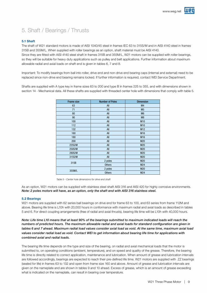
Shafts are supplied with A type key in frame sizes 63 to 200 and type B in frames 225 to 355, and with dimensions shown in section 14 - Mechanical data. All these shafts are supplied with threaded center hole with dimensions that comply with table 5.
5.2 BearingsW21 motors are supplied with 62 series ball bearings on drive end for frame 63 to 100, and 63 series from frame 112M and above. Bearing life time is L10h with 20,000 hours in conformance with maximum radial and axial loads as described in tables 5 and 6. For direct coupling arrangements (free of radial and axial thrusts), bearing life time will be L10h with 40,000 hours.
Note: Life time L10 means that at least 90% of the bearings submitted to maximum indicated loads will reach the numbers of predicted hours. The maximum allowable radial and axial loads for standard configuration are given in tables 6 and 7 ahead. Maximum radial load values consider axial load as void. At the same time, maximum axial load values consider radial load as void. Contact WEI to get information about bearing life time for applications with combined axial and radial loads.
The bearing life time depends on the type and size of the bearing, on radial and axial mechanical loads that the motor is submitted to, on operating conditions (ambient, temperature), and on speed and quality of the grease. Therefore, the bearing life time is directly related to correct application, maintenance and lubrication. When amount of grease and lubrication intervals are followed accordingly, bearings are expected to reach their pre-defined life time. W21 motors are supplied with ZZ bearings (sealed for life) in frames 63 to 132 and open from frame size 160 and above. Amount of grease and lubrication intervals are given on the nameplate and are shown in tables 9 and 10 ahead. Excess of grease, which is an amount of grease exceeding what is indicated on the nameplate, can result in bearing over temperature.
Table 5 - Center hole dimensions for drive end shaft
Frame size Number of Poles Dimension63 All M471 All M580 All M690 All M8100 All M10112 All M10132 All M12160 All M16180 All M16200 All M20
225S/M All M20250S/M All M20280S/M All M20315S/M All M20
315B2 poles M20Others M24
355M/L2 poles M20Others M24
As an option, W21 motors can be supplied with stainless steel shaft AISI 316 and AISI 420 for highly corrosive environments.Note: 2 poles motors will have, as an option, only the shaft end with AISI 316 stainless steel.
www.weg.net
W21 Three Phase Motor10
5.2.1 Bearing lockingFor the standard line, the drive end bearing is locked axially with the external bearing cap in frame sizes 160 up to 200, and with internal and external bearing cap in frame sizes 225 up to 355. The non-drive end bearing is fitted with a spring washer in frame sizes 63 up to 200, and pre-load spring in frame sizes 225 up to 355 to take any axial play. When supplied with roller bearings (optional feature that is available from frame 132), the non-drive end bearing is locked and any axial play is compensated by axial play of the drive end roller bearing. The minimum allowable radial loads for roller bearings are shown in table 8 ahead.
Important: 1 - Special applications Motor operations at different conditions compared to the normal ones, such as ambient temperature, altitude, axial and
radial loads above those given by the tables included in this document require specific and different lubrication intervals from those given herewith.
2 - Roller bearings Roller bearings require minimum radial load so as to ensure correct operation. They are not recommended for direct
coupling arrangement neither for 2 pole motors.3 - Frequency drive operation motors Bearing life time may be reduced when motor is driven by frequency drive and speed above the normal one. The speed
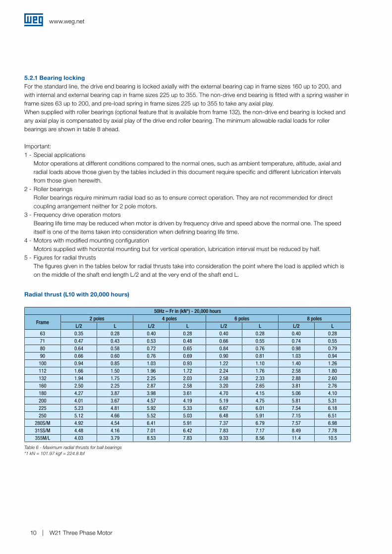
itself is one of the items taken into consideration when defining bearing life time.4 - Motors with modified mounting configuration Motors supplied with horizontal mounting but for vertical operation, lubrication interval must be reduced by half.5 - Figures for radial thrusts The figures given in the tables below for radial thrusts take into consideration the point where the load is applied which is
on the middle of the shaft end length L/2 and at the very end of the shaft end L.
50Hz – Fr in (kN*) - 20,000 hours
Frame2 poles 4 poles 6 poles 8 poles
L/2 L L/2 L L/2 L L/2 L63 0.35 0.28 0.40 0.28 0.40 0.28 0.40 0.2871 0.47 0.43 0.53 0.48 0.66 0.55 0.74 0.5580 0.64 0.58 0.72 0.65 0.84 0.76 0.98 0.7990 0.66 0.60 0.76 0.69 0.90 0.81 1.03 0.94100 0.94 0.85 1.03 0.93 1.22 1.10 1.40 1.26112 1.66 1.50 1.96 1.72 2.24 1.76 2.58 1.80132 1.94 1.75 2.25 2.03 2.58 2.33 2.88 2.60160 2.50 2.25 2.87 2.58 3.20 2.65 3.81 2.76180 4.27 3.87 3.98 3.61 4.70 4.15 5.06 4.10200 4.01 3.67 4.57 4.19 5.19 4.75 5.81 5.31225 5.23 4.81 5.92 5.33 6.67 6.01 7.54 6.18250 5.12 4.66 5.52 5.03 6.48 5.91 7.15 6.51
280S/M 4.92 4.54 6.41 5.91 7.37 6.79 7.57 6.98315S/M 4.48 4.16 7.01 6.42 7.83 7.17 8.49 7.78355M/L 4.03 3.79 8.53 7.83 9.33 8.56 11.4 10.5
Radial thrust (L10 with 20,000 hours)
Table 6 - Maximum radial thrusts for ball bearings*1 kN = 101.97 kgf = 224.8 lbf
www.weg.net
W21 Three Phase Motor 11
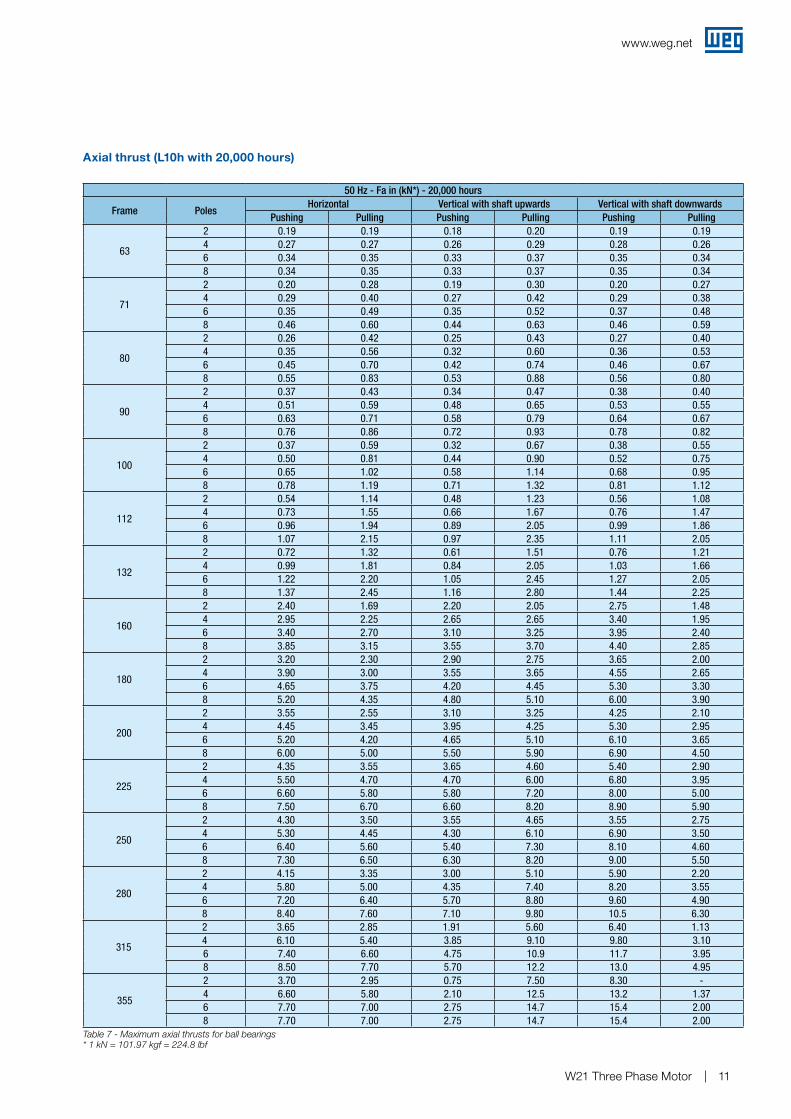
Axial thrust (L10h with 20,000 hours)
50 Hz - Fa in (kN*) - 20,000 hours
Frame PolesHorizontal Vertical with shaft upwards Vertical with shaft downwards
Pushing Pulling Pushing Pulling Pushing Pulling
63
2 0.19 0.19 0.18 0.20 0.19 0.194 0.27 0.27 0.26 0.29 0.28 0.266 0.34 0.35 0.33 0.37 0.35 0.348 0.34 0.35 0.33 0.37 0.35 0.34
71
2 0.20 0.28 0.19 0.30 0.20 0.274 0.29 0.40 0.27 0.42 0.29 0.386 0.35 0.49 0.35 0.52 0.37 0.488 0.46 0.60 0.44 0.63 0.46 0.59
80
2 0.26 0.42 0.25 0.43 0.27 0.404 0.35 0.56 0.32 0.60 0.36 0.536 0.45 0.70 0.42 0.74 0.46 0.678 0.55 0.83 0.53 0.88 0.56 0.80
90
2 0.37 0.43 0.34 0.47 0.38 0.404 0.51 0.59 0.48 0.65 0.53 0.556 0.63 0.71 0.58 0.79 0.64 0.678 0.76 0.86 0.72 0.93 0.78 0.82
100
2 0.37 0.59 0.32 0.67 0.38 0.554 0.50 0.81 0.44 0.90 0.52 0.756 0.65 1.02 0.58 1.14 0.68 0.958 0.78 1.19 0.71 1.32 0.81 1.12
112
2 0.54 1.14 0.48 1.23 0.56 1.084 0.73 1.55 0.66 1.67 0.76 1.476 0.96 1.94 0.89 2.05 0.99 1.868 1.07 2.15 0.97 2.35 1.11 2.05
132
2 0.72 1.32 0.61 1.51 0.76 1.214 0.99 1.81 0.84 2.05 1.03 1.666 1.22 2.20 1.05 2.45 1.27 2.058 1.37 2.45 1.16 2.80 1.44 2.25
160
2 2.40 1.69 2.20 2.05 2.75 1.484 2.95 2.25 2.65 2.65 3.40 1.956 3.40 2.70 3.10 3.25 3.95 2.408 3.85 3.15 3.55 3.70 4.40 2.85
180
2 3.20 2.30 2.90 2.75 3.65 2.004 3.90 3.00 3.55 3.65 4.55 2.656 4.65 3.75 4.20 4.45 5.30 3.308 5.20 4.35 4.80 5.10 6.00 3.90
200
2 3.55 2.55 3.10 3.25 4.25 2.104 4.45 3.45 3.95 4.25 5.30 2.956 5.20 4.20 4.65 5.10 6.10 3.658 6.00 5.00 5.50 5.90 6.90 4.50
225
2 4.35 3.55 3.65 4.60 5.40 2.904 5.50 4.70 4.70 6.00 6.80 3.956 6.60 5.80 5.80 7.20 8.00 5.008 7.50 6.70 6.60 8.20 8.90 5.90
250
2 4.30 3.50 3.55 4.65 3.55 2.754 5.30 4.45 4.30 6.10 6.90 3.506 6.40 5.60 5.40 7.30 8.10 4.608 7.30 6.50 6.30 8.20 9.00 5.50
280
2 4.15 3.35 3.00 5.10 5.90 2.204 5.80 5.00 4.35 7.40 8.20 3.556 7.20 6.40 5.70 8.80 9.60 4.908 8.40 7.60 7.10 9.80 10.5 6.30
315
2 3.65 2.85 1.91 5.60 6.40 1.134 6.10 5.40 3.85 9.10 9.80 3.106 7.40 6.60 4.75 10.9 11.7 3.958 8.50 7.70 5.70 12.2 13.0 4.95
355
2 3.70 2.95 0.75 7.50 8.30 -4 6.60 5.80 2.10 12.5 13.2 1.376 7.70 7.00 2.75 14.7 15.4 2.008 7.70 7.00 2.75 14.7 15.4 2.00
Table 7 - Maximum axial thrusts for ball bearings* 1 kN = 101.97 kgf = 224.8 lbf
www.weg.net
W21 Three Phase Motor12
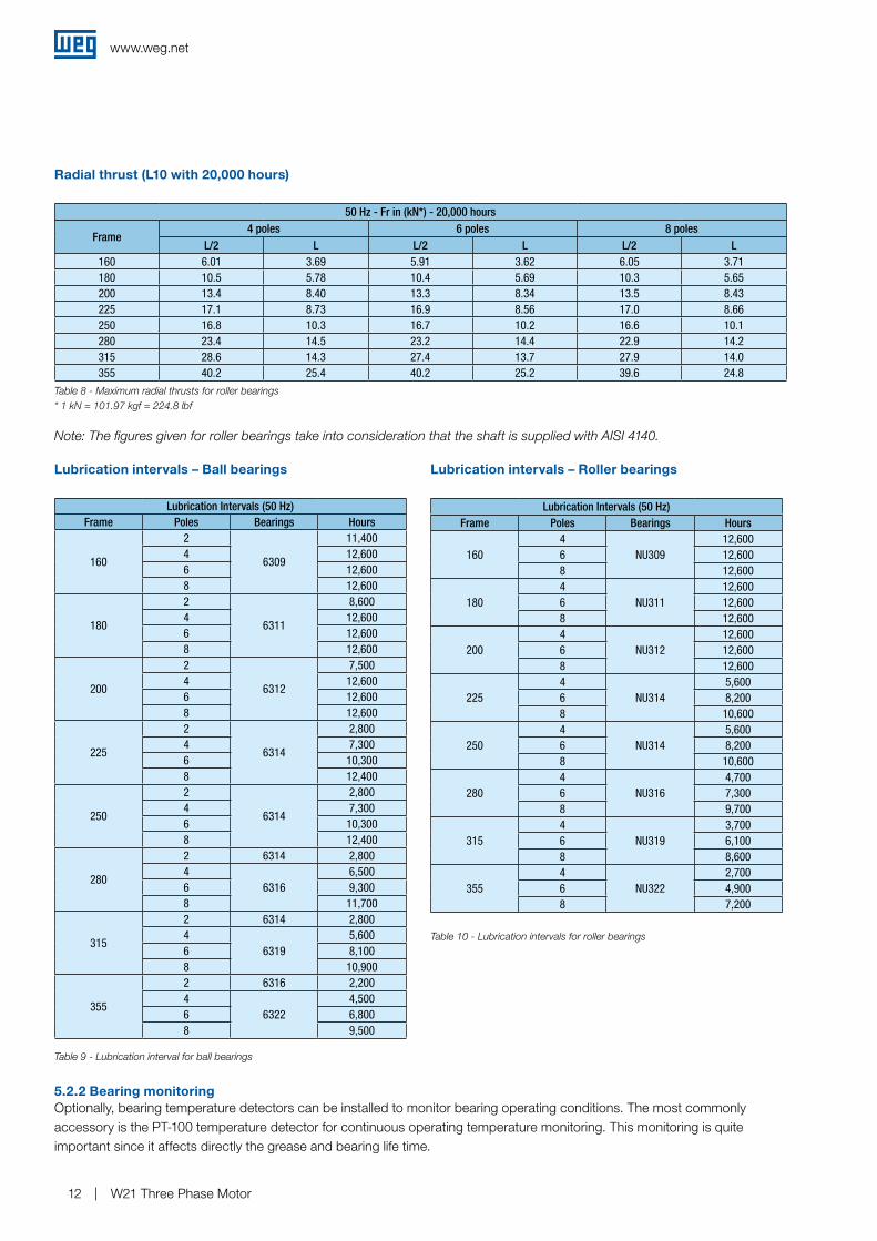
Radial thrust (L10 with 20,000 hours)
5.2.2 Bearing monitoring
Lubrication intervals – Ball bearings Lubrication intervals – Roller bearings
50 Hz - Fr in (kN*) - 20,000 hours
Frame4 poles 6 poles 8 poles
L/2 L L/2 L L/2 L160 6.01 3.69 5.91 3.62 6.05 3.71180 10.5 5.78 10.4 5.69 10.3 5.65200 13.4 8.40 13.3 8.34 13.5 8.43225 17.1 8.73 16.9 8.56 17.0 8.66250 16.8 10.3 16.7 10.2 16.6 10.1280 23.4 14.5 23.2 14.4 22.9 14.2315 28.6 14.3 27.4 13.7 27.9 14.0355 40.2 25.4 40.2 25.2 39.6 24.8
Table 8 - Maximum radial thrusts for roller bearings
Table 9 - Lubrication interval for ball bearings
Table 10 - Lubrication intervals for roller bearings
Note: The figures given for roller bearings take into consideration that the shaft is supplied with AISI 4140.
Lubrication Intervals (50 Hz)Frame Poles Bearings Hours
160
2
6309
11,4004 12,6006 12,6008 12,600
180
2
6311
8,6004 12,6006 12,6008 12,600
200
2
6312
7,5004 12,6006 12,6008 12,600
225
2
6314
2,8004 7,3006 10,3008 12,400
250
2
6314
2,8004 7,3006 10,3008 12,400
280
2 6314 2,8004
63166,500
6 9,3008 11,700
315
2 6314 2,8004
63195,600
6 8,1008 10,900
355
2 6316 2,2004
63224,500
6 6,8008 9,500
Lubrication Intervals (50 Hz)Frame Poles Bearings Hours
1604
NU30912,600
6 12,6008 12,600
1804
NU31112,600
6 12,6008 12,600
2004
NU31212,600
6 12,6008 12,600
2254
NU3145,600
6 8,2008 10,600
2504
NU3145,600
6 8,2008 10,600
2804
NU3164,700
6 7,3008 9,700
3154
NU3193,700
6 6,1008 8,600
3554
NU3222,700
6 4,9008 7,200
Optionally, bearing temperature detectors can be installed to monitor bearing operating conditions. The most commonly accessory is the PT-100 temperature detector for continuous operating temperature monitoring. This monitoring is quite important since it affects directly the grease and bearing life time.
* 1 kN = 101.97 kgf = 224.8 lbf
www.weg.net
W21 Three Phase Motor 13
6. Mounting
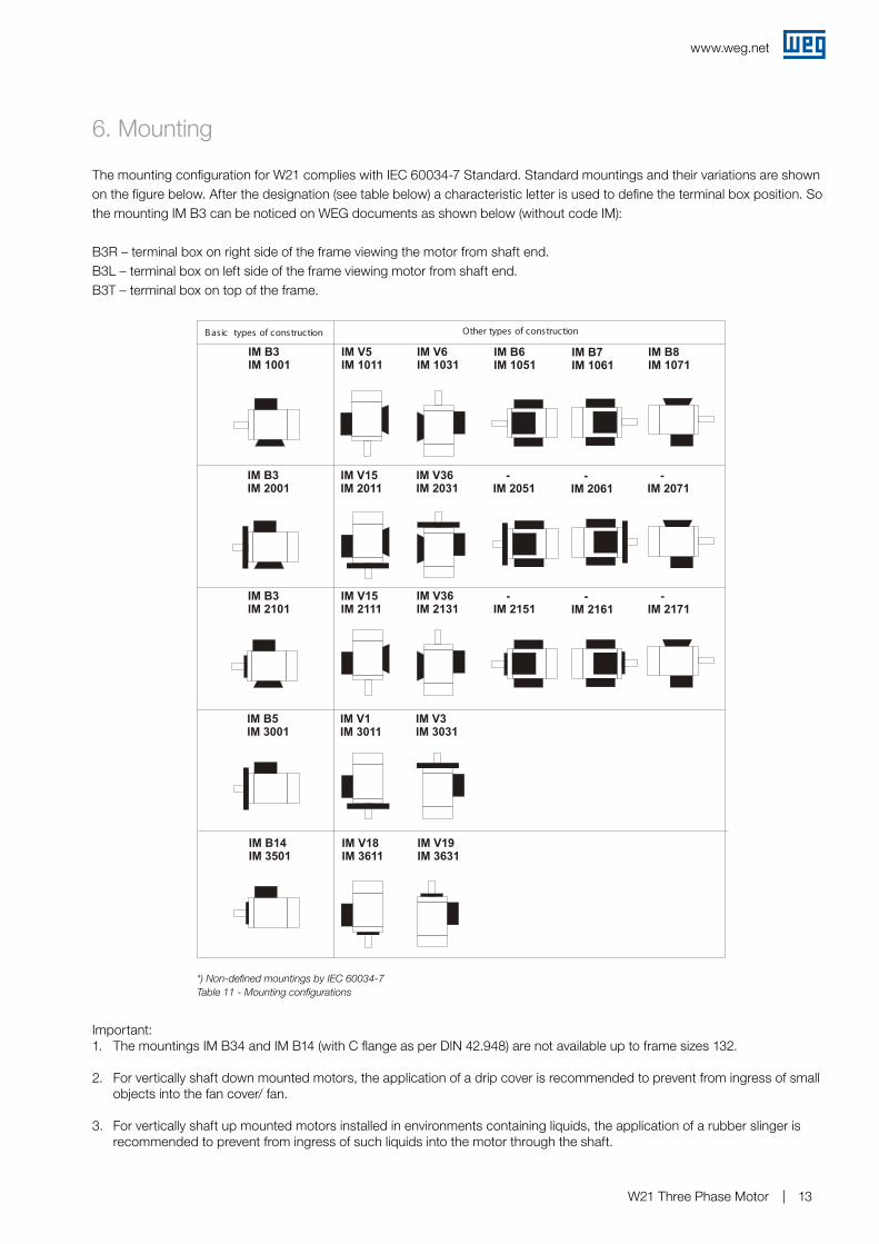
The mounting configuration for W21 complies with IEC 60034-7 Standard. Standard mountings and their variations are shown on the figure below. After the designation (see table below) a characteristic letter is used to define the terminal box position. So the mounting IM B3 can be noticed on WEG documents as shown below (without code IM):
B3R – terminal box on right side of the frame viewing the motor from shaft end.B3L – terminal box on left side of the frame viewing motor from shaft end.B3T – terminal box on top of the frame.
Table 11 - Mounting configurations*) Non-defined mountings by IEC 60034-7
Important:1. The mountings IM B34 and IM B14 (with C flange as per DIN 42.948) are not available up to frame sizes 132.
2. For vertically shaft down mounted motors, the application of a drip cover is recommended to prevent from ingress of small objects into the fan cover/ fan.
3. For vertically shaft up mounted motors installed in environments containing liquids, the application of a rubber slinger is recommended to prevent from ingress of such liquids into the motor through the shaft.
B asic types of construction
IM B3IM 1001
IM B3IM 2001
IM B3IM 2101
IM B5IM 3001
IM B14IM 3501
IM V5IM 1011
IM V15IM 2011
IM V15IM 2111
IM V1IM 3011
IM V18IM 3611
IM V6IM 1031
IM V36IM 2031
IM V36IM 2131
IM V3IM 3031
IM V19IM 3631
IM B6IM 1051
-IM 2051
-IM 2151
IM B7IM 1061
-IM 2061
-IM 2161
IM B8IM 1071
-IM 2071
-IM 2171
Other types of construction
www.weg.net
W21 Three Phase Motor14
7. Degree of protection / Painting
7.1 Degree of protectionThe W21 motors are supplied with degree of protection in conformance with 60034-5. They are IP55 which means:
a) First characteristic numeral 5: machine protected against dust. The enclosure is protected against contacts moving parts and ingress of dust not totally prevented, but dust does not enter in sufficient quantity to interfere with satisfactory operation of the machine.
b) Second characteristic numeral 5: Machine protected against water jets. Water projected by a nozzle against the machine from any direction shall have no harmful effect.
7.2 PaintingThe W21 motors are supplied as standard with painting plan 203A (internal WEG designation), consisting of:
g Primer: one coat with 20 to 55 µm of alkyd primer;g Finishing: one coat with 50 to 75 µm of alky synthetic enamel.
This painting plan can be applied to normal ambient applications, slightly severe, protected or unprotected, for industrial applications, with low relative humidity, regular temperature variations and environments containing SO2.
Note: This painting plan is not recommended for direct exposure to acid steam, alkalis, solvents and salty environments.
Optionally, other painting plans are available, which are suitable to guarantee additional protection aggressive environments, either protected or unprotected (see Section 12 - Optional features).
7.2.1 Tropicalized paintingHigh humidity can result in premature insulation system deterioration which is the main component that ensures motor life time. Any ambient with up to 95% of relative humidity does not require additional protection, other than space heaters to avoid water condensation inside the motor. However, for any ambient with relative humidity above 95%, an epoxy painting is applied on all inside motor components which is known as tropicalized painting. If humidity is more than 95% it should be specified in the enquiry to ensure this tropicalized painting.
www.weg.net
W21 Three Phase Motor 15
8. Ambient & Insulation
The rated output power given on the electrical tables, unless otherwise specified, refers to continuous duty operation S1, as per IEC 60034-1 and at following environments:
g With temperature varying between -20°C to +50°C;g With altitudes up to 1000 meters above sea level;g With relative humidity up to 60% (above 60% we suggest to install space heaters to avoid accumulation of condensed water inside the motor).
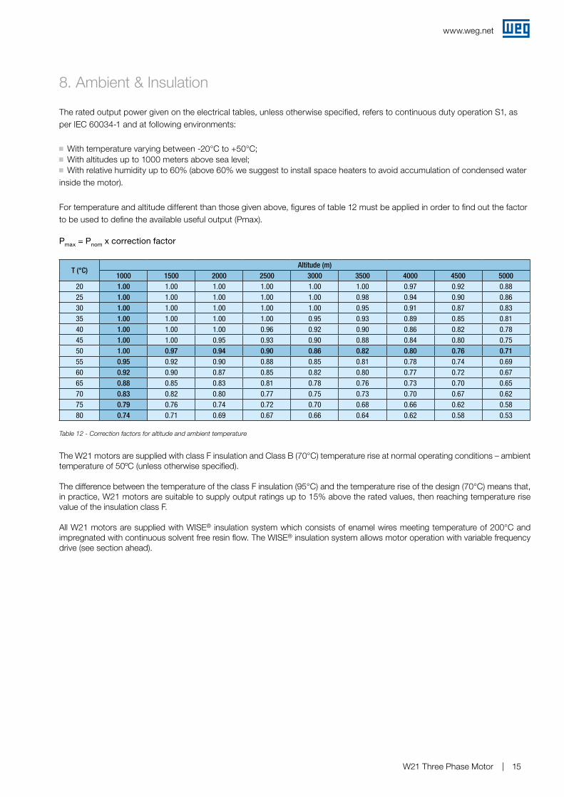
For temperature and altitude different than those given above, figures of table 12 must be applied in order to find out the factor to be used to define the available useful output (Pmax).
Pmax = Pnom x correction factor
Table 12 - Correction factors for altitude and ambient temperature
The W21 motors are supplied with class F insulation and Class B (70°C) temperature rise at normal operating conditions – ambient temperature of 50ºC (unless otherwise specified).
The difference between the temperature of the class F insulation (95°C) and the temperature rise of the design (70°C) means that, in practice, W21 motors are suitable to supply output ratings up to 15% above the rated values, then reaching temperature rise value of the insulation class F.
All W21 motors are supplied with WISE® insulation system which consists of enamel wires meeting temperature of 200°C and impregnated with continuous solvent free resin flow. The WISE® insulation system allows motor operation with variable frequency drive (see section ahead).
T (°C)Altitude (m)
1000 1500 2000 2500 3000 3500 4000 4500 500020 1.00 1.00 1.00 1.00 1.00 1.00 0.97 0.92 0.8825 1.00 1.00 1.00 1.00 1.00 0.98 0.94 0.90 0.8630 1.00 1.00 1.00 1.00 1.00 0.95 0.91 0.87 0.8335 1.00 1.00 1.00 1.00 0.95 0.93 0.89 0.85 0.8140 1.00 1.00 1.00 0.96 0.92 0.90 0.86 0.82 0.7845 1.00 1.00 0.95 0.93 0.90 0.88 0.84 0.80 0.7550 1.00 0.97 0.94 0.90 0.86 0.82 0.80 0.76 0.7155 0.95 0.92 0.90 0.88 0.85 0.81 0.78 0.74 0.6960 0.92 0.90 0.87 0.85 0.82 0.80 0.77 0.72 0.6765 0.88 0.85 0.83 0.81 0.78 0.76 0.73 0.70 0.6570 0.83 0.82 0.80 0.77 0.75 0.73 0.70 0.67 0.6275 0.79 0.76 0.74 0.72 0.70 0.68 0.66 0.62 0.5880 0.74 0.71 0.69 0.67 0.66 0.64 0.62 0.58 0.53
www.weg.net
W21 Three Phase Motor16
9. Variable frequency drive application
9.1 Considerations about rated voltageThe stator of W21 motors is supplied with class F insulation and it is suitable for DOL starting or with variable frequency drive. Optionally, these motors can be supplied with class H insulation.
These motors are supplied with WEG exclusive insulation system - WISE® (WEG Insulation System Evolution) – which ensures superior electric insulation characteristics. They are suitable for variable frequency drive application, taking into account the limits shown in table 13.
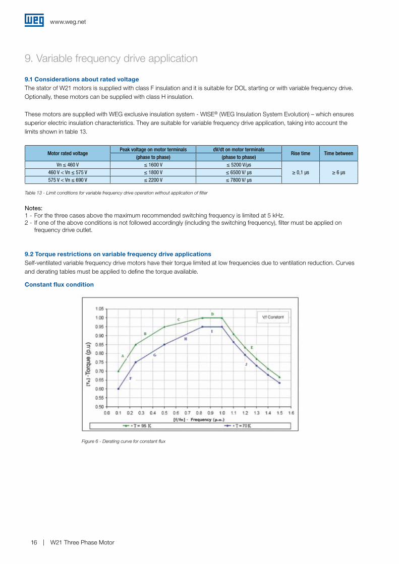
9.2 Torque restrictions on variable frequency drive applicationsSelf-ventilated variable frequency drive motors have their torque limited at low frequencies due to ventilation reduction. Curves and derating tables must be applied to define the torque available.
Motor rated voltagePeak voltage on motor terminals dV/dt on motor terminals
Rise time Time between(phase to phase) (phase to phase)
Vn ≤ 460 V ≤ 1600 V ≤ 5200 V/µs≥ 0,1 µs ≥ 6 µs460 V < Vn ≤ 575 V ≤ 1800 V ≤ 6500 V/ µs
575 V < Vn ≤ 690 V ≤ 2200 V ≤ 7800 V/ µs
Table 13 - Limit conditions for variable frequency drive operation without application of filter
Figure 6 - Derating curve for constant flux
Notes: 1 - For the three cases above the maximum recommended switching frequency is limited at 5 kHz.2 - If one of the above conditions is not followed accordingly (including the switching frequency), filter must be applied on
frequency drive outlet.
Constant flux condition
www.weg.net
W21 Three Phase Motor 17
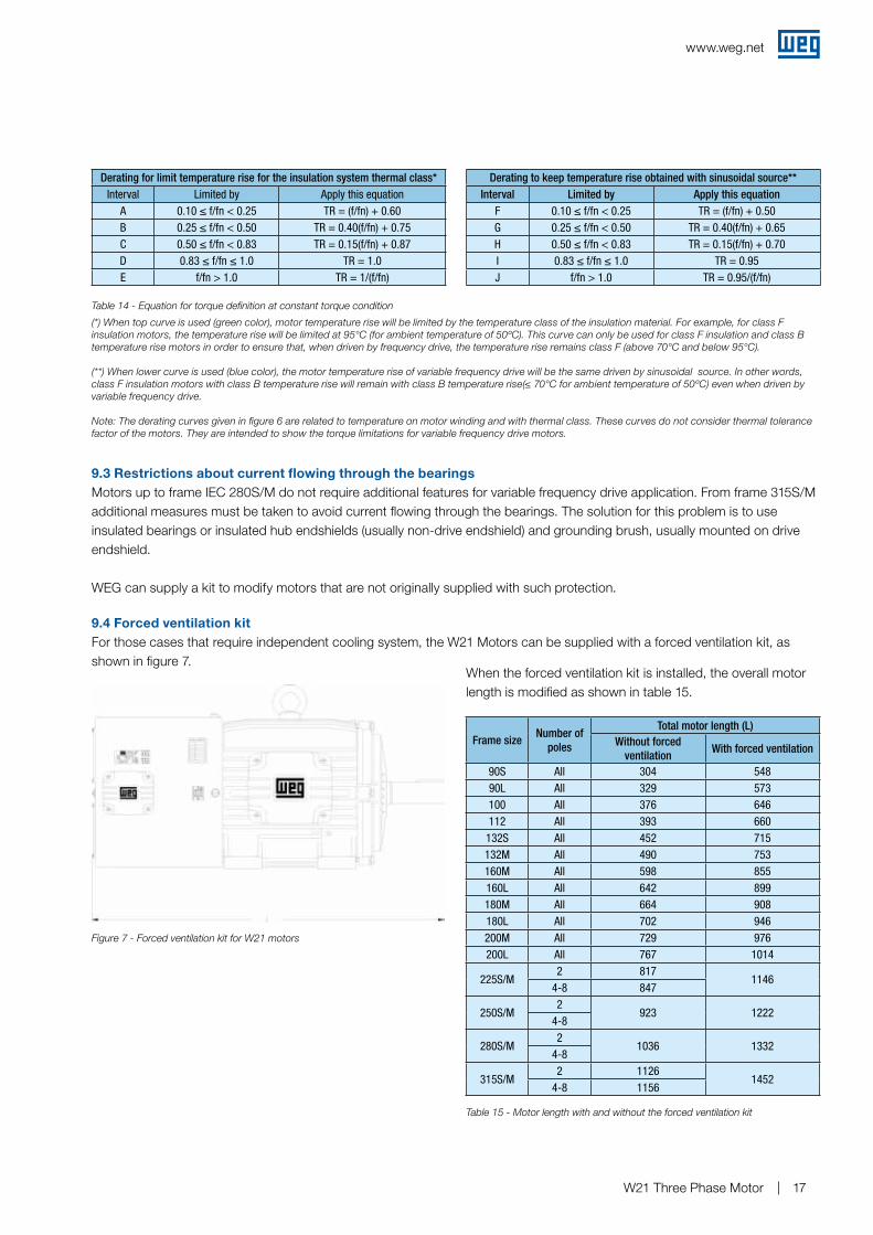
Table 14 - Equation for torque definition at constant torque condition
Derating for limit temperature rise for the insulation system thermal class*Interval Limited by Apply this equation
A 0.10 ≤ f/fn < 0.25 TR = (f/fn) + 0.60B 0.25 ≤ f/fn < 0.50 TR = 0.40(f/fn) + 0.75C 0.50 ≤ f/fn < 0.83 TR = 0.15(f/fn) + 0.87D 0.83 ≤ f/fn ≤ 1.0 TR = 1.0E f/fn > 1.0 TR = 1/(f/fn)
Derating to keep temperature rise obtained with sinusoidal source**Interval Limited by Apply this equation
F 0.10 ≤ f/fn < 0.25 TR = (f/fn) + 0.50G 0.25 ≤ f/fn < 0.50 TR = 0.40(f/fn) + 0.65H 0.50 ≤ f/fn < 0.83 TR = 0.15(f/fn) + 0.70I 0.83 ≤ f/fn ≤ 1.0 TR = 0.95J f/fn > 1.0 TR = 0.95/(f/fn)
(*) When top curve is used (green color), motor temperature rise will be limited by the temperature class of the insulation material. For example, for class F insulation motors, the temperature rise will be limited at 95°C (for ambient temperature of 50ºC). This curve can only be used for class F insulation and class B temperature rise motors in order to ensure that, when driven by frequency drive, the temperature rise remains class F (above 70°C and below 95°C).
(**) When lower curve is used (blue color), the motor temperature rise of variable frequency drive will be the same driven by sinusoidal source. In other words, class F insulation motors with class B temperature rise will remain with class B temperature rise(≤ 70°C for ambient temperature of 50ºC) even when driven by variable frequency drive.
Note: The derating curves given in figure 6 are related to temperature on motor winding and with thermal class. These curves do not consider thermal tolerance factor of the motors. They are intended to show the torque limitations for variable frequency drive motors.
9.3 Restrictions about current flowing through the bearingsMotors up to frame IEC 280S/M do not require additional features for variable frequency drive application. From frame 315S/M additional measures must be taken to avoid current flowing through the bearings. The solution for this problem is to use insulated bearings or insulated hub endshields (usually non-drive endshield) and grounding brush, usually mounted on drive endshield.
WEG can supply a kit to modify motors that are not originally supplied with such protection.
9.4 Forced ventilation kitFor those cases that require independent cooling system, the W21 Motors can be supplied with a forced ventilation kit, as shown in figure 7.
When the forced ventilation kit is installed, the overall motor length is modified as shown in table 15.
Figure 7 - Forced ventilation kit for W21 motors
Frame sizeNumber of
poles
Total motor length (L)Without forced
ventilationWith forced ventilation
90S All 304 54890L All 329 573100 All 376 646112 All 393 660
132S All 452 715132M All 490 753160M All 598 855160L All 642 899180M All 664 908180L All 702 946200M All 729 976200L All 767 1014
225S/M2 817
11464-8 847
250S/M2
923 12224-8
280S/M2
1036 13324-8
315S/M2 1126
14524-8 1156
Table 15 - Motor length with and without the forced ventilation kit
www.weg.net
W21 Three Phase Motor18
10. Tolerances for electrical data
The following tolerance figures are allowed in accordance with IEC 60034-1:
Efficiency (η)-0.15 (1-η) for Pnom ≤ 150 kW-0.1 (1-η) for Pnom > 150 kWWhere η is a decimal number
Power factor
1 - cos Φ
6Minimum 0.02Maximum 0.07
Slip± 20% for Pnom ≥ 1 kW± 30 % for Pnom < 1 kW
Starting current+ 20%
(without lower limit)
Starting torque - 15% + 25%Breakdown torque - 10 %Moment of inertia ± 10 %
( (
www.weg.net
W21 Three Phase Motor 19
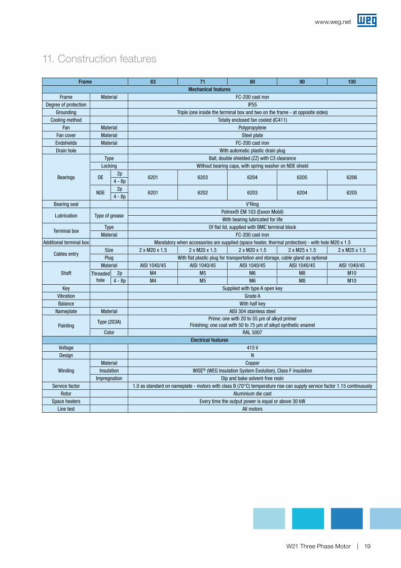
11. Construction features
Frame 63 71 80 90 100Mechanical features
Frame Material FC-200 cast ironDegree of protection IP55
Grounding Triple (one inside the terminal box and two on the frame - at opposite sides)Cooling method Totally enclosed fan cooled (IC411)
Fan Material PolypropyleneFan cover Material Steel plateEndshields Material FC-200 cast ironDrain hole With automatic plastic drain plug
Bearings
Type Ball, double shielded (ZZ) with C3 clearanceLocking Without bearing caps, with spring washer on NDE shield
DE2p
6201 6203 6204 6205 62064 - 8p
NDE2p
6201 6202 6203 6204 62054 - 8p
Bearing seal V'Ring
Lubrication Type of greasePolirex® EM 103 (Exxon Mobil)With bearing lubricated for life
Terminal boxType Of flat lid, supplied with BMC terminal block
Material FC-200 cast ironAdditional terminal box Mandatory when accessories are supplied (space heater, thermal protection) - with hole M20 x 1.5
Cables entrySize 2 x M20 x 1.5 2 x M20 x 1.5 2 x M20 x 1.5 2 x M25 x 1.5 2 x M25 x 1.5Plug With flat plastic plug for transportation and storage, cable gland as optional
ShaftMaterial AISI 1040/45 AISI 1040/45 AISI 1040/45 AISI 1040/45 AISI 1040/45
Threaded hole
2p M4 M5 M6 M8 M104 - 8p M4 M5 M6 M8 M10
Key Supplied with type A open keyVibration Grade ABalance With half key
Nameplate Material AISI 304 stainless steel
PaintingType (203A)
Prime: one with 20 to 55 µm of alkyd primerFinishing: one coat with 50 to 75 µm of alkyd synthetic enamel
Color RAL 5007Electrical features
Voltage 415 VDesign N
WindingMaterial Copper
Insulation WISE® (WEG Insulation System Evolution), Class F insulationImpregnation Dip and bake solvent-free resin
Service factor 1.0 as standard on nameplate - motors with class B (70°C) temperature rise can supply service factor 1.15 continuouslyRotor Aluminium die cast
Space heaters Every time the output power is equal or above 30 kWLine test All motors
www.weg.net
W21 Three Phase Motor20
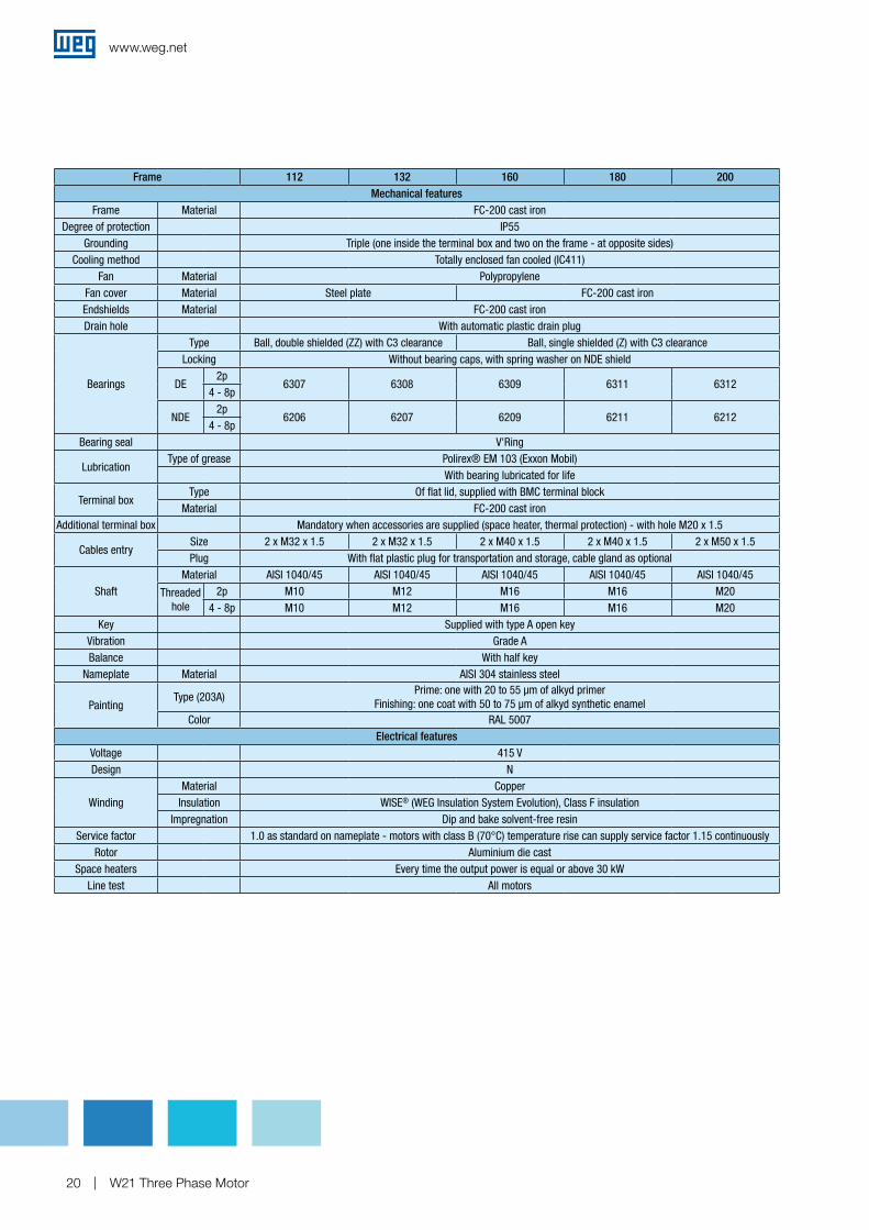
Frame 112 132 160 180 200Mechanical features
Frame Material FC-200 cast ironDegree of protection IP55
Grounding Triple (one inside the terminal box and two on the frame - at opposite sides)Cooling method Totally enclosed fan cooled (IC411)
Fan Material PolypropyleneFan cover Material Steel plate FC-200 cast ironEndshields Material FC-200 cast ironDrain hole With automatic plastic drain plug
Bearings
Type Ball, double shielded (ZZ) with C3 clearance Ball, single shielded (Z) with C3 clearanceLocking Without bearing caps, with spring washer on NDE shield
DE2p
6307 6308 6309 6311 63124 - 8p
NDE2p
6206 6207 6209 6211 62124 - 8p
Bearing seal V'Ring
LubricationType of grease Polirex® EM 103 (Exxon Mobil)
With bearing lubricated for life
Terminal boxType Of flat lid, supplied with BMC terminal block
Material FC-200 cast ironAdditional terminal box Mandatory when accessories are supplied (space heater, thermal protection) - with hole M20 x 1.5
Cables entrySize 2 x M32 x 1.5 2 x M32 x 1.5 2 x M40 x 1.5 2 x M40 x 1.5 2 x M50 x 1.5Plug With flat plastic plug for transportation and storage, cable gland as optional
ShaftMaterial AISI 1040/45 AISI 1040/45 AISI 1040/45 AISI 1040/45 AISI 1040/45
Threaded hole
2p M10 M12 M16 M16 M204 - 8p M10 M12 M16 M16 M20
Key Supplied with type A open keyVibration Grade ABalance With half key
Nameplate Material AISI 304 stainless steel
PaintingType (203A)
Prime: one with 20 to 55 µm of alkyd primerFinishing: one coat with 50 to 75 µm of alkyd synthetic enamel
Color RAL 5007Electrical features
Voltage 415 VDesign N
WindingMaterial Copper
Insulation WISE® (WEG Insulation System Evolution), Class F insulationImpregnation Dip and bake solvent-free resin
Service factor 1.0 as standard on nameplate - motors with class B (70°C) temperature rise can supply service factor 1.15 continuouslyRotor Aluminium die cast
Space heaters Every time the output power is equal or above 30 kWLine test All motors
www.weg.net
W21 Three Phase Motor 21
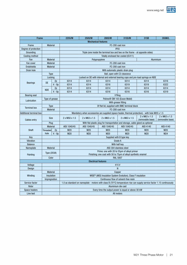
Frame 225S/M 250S/M 280S/M 315S/M 315B 355M/LMechanical features
Frame Material FC-200 cast ironDegree of protection IP55
Grounding Triple (one inside the terminal box and two on the frame - at opposite sides)Cooling method Totally enclosed fan cooled (IC411)
Fan Material Polypropylene AluminiumFan cover Material FC-200 cast ironEndshields Material FC-200 cast ironDrain hole With automatic plastic drain plug
Bearings
Type Ball, open with C3 clearanceLocking Locked on DE with internal and external bearing caps and pre-load springs on NDE
DE2p 6314 6314 6314 6314 6314 6316
4 - 8p 6314 6314 6316 6319 6319 6322
NDE2p 6314 6314 6314 6314 6314 6314
4 - 8p 6314 6314 6316 6316 6316 6319Bearing seal V'Ring
LubricationType of grease Polirex® EM 103 (Exxon Mobil)
With grease fitting
Terminal boxType Of flat lid, supplied with BMC terminal block
Material FC-200 cast ironAdditional terminal box Mandatory when accessories are supplied (space heater, thermal protection) - with hole M20 x 1.5
Cables entrySize 2 x M50 x 1.5 2 x M63 x 1.5 2 x M63 x 1.5 2 x M63 x 1.5
2 x M63 x 1.5(removable base)
2 x M63 x 1.5(removable base)
Plug With flat plastic plug for transportation and storage, cable gland as optional
ShaftMaterial AISI 1040/45 AISI 1040/45 AISI 1040/45 AISI 1040/45 AISI 4140 AISI 4140
Threaded hole
2p M20 M20 M20 M20 M20 M204 - 8p M20 M20 M20 M20 M20 M24
Key Supplied with B type keyVibration Grade ABalance With half key
Nameplate Material AISI 304 stainless steel
PaintingType (203A)
Prime: one with 20 to 55µm of alkyd primerFinishing: one coat with 50 to 75µm of alkyd synthetic enamel
Color RAL 5007Electrical features
Voltage 415 VDesign N
WindingMaterial Copper
Insulation WISE® (WEG Insulation System Evolution), Class F insulationImpregnation Continuous flow of solvent-free resin
Service factor 1.0 as standard on nameplate - motors with class B (70°C) temperature rise can supply service factor 1.15 continuouslyRotor Aluminium die cast
Space heaters Every time the output power is equal or above 30 kWLine test All motors
www.weg.net
W21 Three Phase Motor22
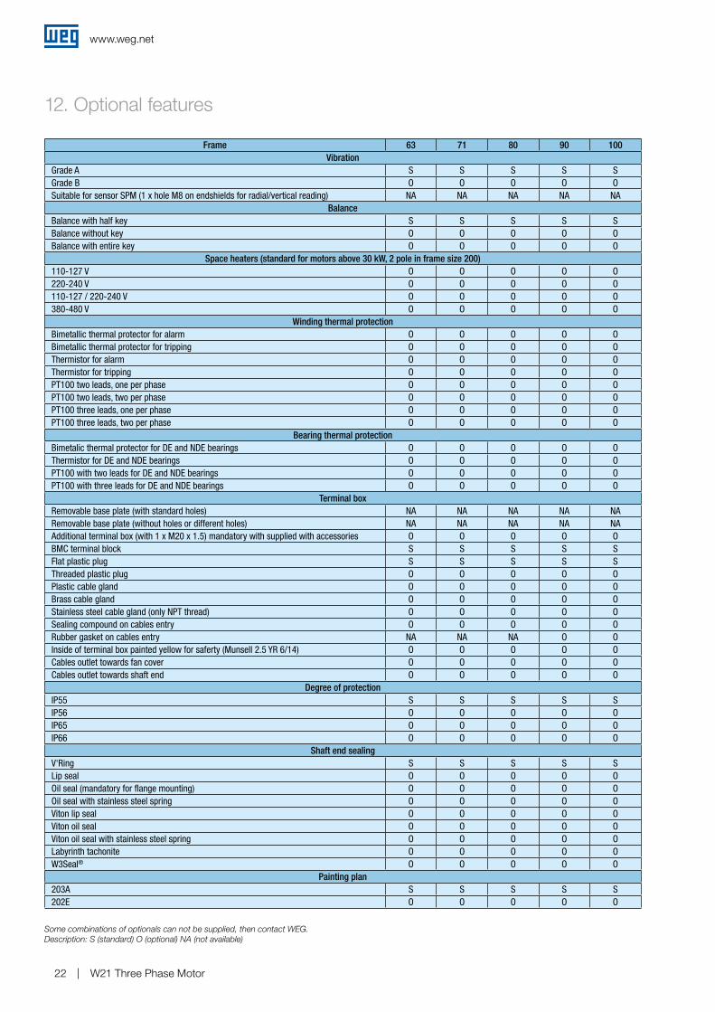
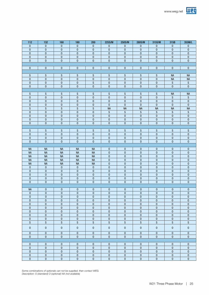
12. Optional features
Frame 63 71 80 90 100Vibration
Grade A S S S S SGrade B O O O O OSuitable for sensor SPM (1 x hole M8 on endshields for radial/vertical reading) NA NA NA NA NA
BalanceBalance with half key S S S S SBalance without key O O O O OBalance with entire key O O O O O
Space heaters (standard for motors above 30 kW, 2 pole in frame size 200)110-127 V O O O O O220-240 V O O O O O110-127 / 220-240 V O O O O O380-480 V O O O O O
Winding thermal protectionBimetallic thermal protector for alarm O O O O OBimetallic thermal protector for tripping O O O O OThermistor for alarm O O O O OThermistor for tripping O O O O OPT100 two leads, one per phase O O O O OPT100 two leads, two per phase O O O O OPT100 three leads, one per phase O O O O OPT100 three leads, two per phase O O O O O
Bearing thermal protectionBimetalic thermal protector for DE and NDE bearings O O O O OThermistor for DE and NDE bearings O O O O OPT100 with two leads for DE and NDE bearings O O O O OPT100 with three leads for DE and NDE bearings O O O O O
Terminal boxRemovable base plate (with standard holes) NA NA NA NA NARemovable base plate (without holes or different holes) NA NA NA NA NAAdditional terminal box (with 1 x M20 x 1.5) mandatory with supplied with accessories O O O O OBMC terminal block S S S S SFlat plastic plug S S S S SThreaded plastic plug O O O O OPlastic cable gland O O O O OBrass cable gland O O O O OStainless steel cable gland (only NPT thread) O O O O OSealing compound on cables entry O O O O ORubber gasket on cables entry NA NA NA O OInside of terminal box painted yellow for saferty (Munsell 2.5 YR 6/14) O O O O OCables outlet towards fan cover O O O O OCables outlet towards shaft end O O O O O
Degree of protectionIP55 S S S S SIP56 O O O O OIP65 O O O O OIP66 O O O O O
Shaft end sealingV'Ring S S S S SLip seal O O O O OOil seal (mandatory for flange mounting) O O O O OOil seal with stainless steel spring O O O O OViton lip seal O O O O OViton oil seal O O O O OViton oil seal with stainless steel spring O O O O OLabyrinth tachonite O O O O OW3Seal® O O O O O
Painting plan203A S S S S S202E O O O O O
Some combinations of optionals can not be supplied, then contact WEG.Description: S (standard) O (optional) NA (not available)
www.weg.net
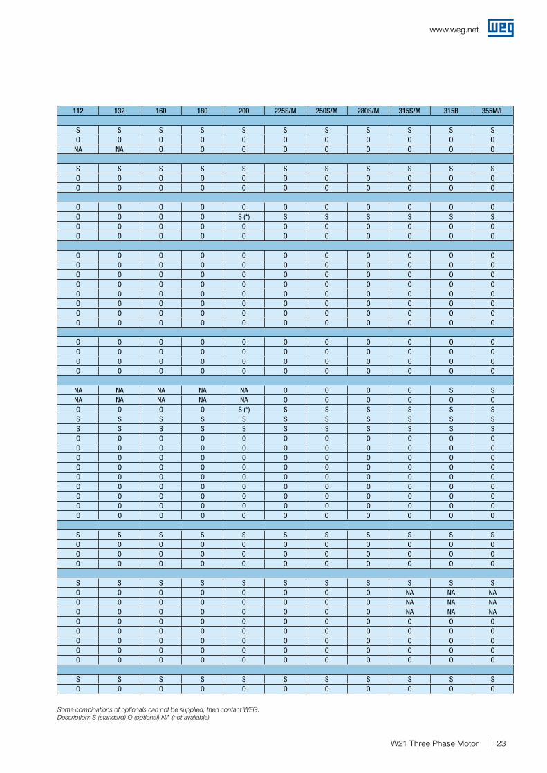
W21 Three Phase Motor 23
Some combinations of optionals can not be supplied, then contact WEG.Description: S (standard) O (optional) NA (not available)
112 132 160 180 200 225S/M 250S/M 280S/M 315S/M 315B 355M/L
S S S S S S S S S S SO O O O O O O O O O O
NA NA O O O O O O O O O
S S S S S S S S S S SO O O O O O O O O O OO O O O O O O O O O O
O O O O O O O O O O OO O O O S (*) S S S S S SO O O O O O O O O O OO O O O O O O O O O O
O O O O O O O O O O OO O O O O O O O O O OO O O O O O O O O O OO O O O O O O O O O OO O O O O O O O O O OO O O O O O O O O O OO O O O O O O O O O OO O O O O O O O O O O
O O O O O O O O O O OO O O O O O O O O O OO O O O O O O O O O OO O O O O O O O O O O
NA NA NA NA NA O O O O S SNA NA NA NA NA O O O O O OO O O O S (*) S S S S S SS S S S S S S S S S SS S S S S S S S S S SO O O O O O O O O O OO O O O O O O O O O OO O O O O O O O O O OO O O O O O O O O O OO O O O O O O O O O OO O O O O O O O O O OO O O O O O O O O O OO O O O O O O O O O OO O O O O O O O O O O
S S S S S S S S S S SO O O O O O O O O O OO O O O O O O O O O OO O O O O O O O O O O
S S S S S S S S S S SO O O O O O O O NA NA NAO O O O O O O O NA NA NAO O O O O O O O NA NA NAO O O O O O O O O O OO O O O O O O O O O OO O O O O O O O O O OO O O O O O O O O O OO O O O O O O O O O O
S S S S S S S S S S SO O O O O O O O O O O
www.weg.net
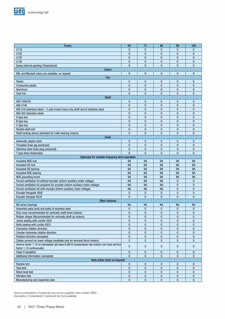
W21 Three Phase Motor24
Frame 63 71 80 90 100211E O O O O O212E O O O O O212P O O O O O213E O O O O OEpoxy internal painting (Tropicalized) O O O O O
ColorsRAL and Munsell colors are available, on request O O O O O
FanPlastic S S S S SConductive plastic O O O O OAluminum O O O O OCast iron O O O O O
ShaftAISI 1040/45 S S S S SAISI 4140 O O O O OAISI 316 (stainless steel) – 2 pole motors have only shaft end of stainless steel O O O O OAISI 420 (stainless steel) O O O O OA type key S S S S SB type key O O O O OC type key O O O O ODouble shaft end O O O O OShaft locking device (standard for roller bearing motors) O O O O O
DrainAutomatic plastic drain S S S S SThreaded drain plg (enclosed) O O O O OStainless steel drain plug (enclosed) O O O O OT type drain (Automatic) O O O O O
Optionals for variable frequency drive operationInsulated NDE hub NA NA NA NA NAInsulated DE hub NA NA NA NA NAInsulated DE bearing NA NA NA NA NAInsulated NDE bearing NA NA NA NA NANDE grounding brush NA NA NA NA NAForced ventilation kit without encoder (inform auxiliary motor voltage) NA NA NA O OForced ventilation kit prepared for encoder (inform auxiliary motor voltage) NA NA NA O OForced ventilation kit with encoder (inform auxiliary motor voltage) NA NA NA O OEncoder Hengstler RI58 O O O O OEncoder Dynapar HS35 O O O O O
Other featuresNU series bearings NA NA NA NA NAAssembly parts (nuts and bolts) of stainless steel O O O O ODrip cover (recommended for vertically shaft down motors) O O O O ORubber slinger (Recommended for vertically shaft up motors) O O O O OJoints sealing with Loctite 5923 O O O O OBolts sealing with Loctite 5923 O O O O OClockwise rotation direction O O O O OCounter clockwise rotation direction O O O O ORotation direction nameplate O O O O OCables connect on lower voltage (available only for terminal block motors) S S S S SService factor 1.15 on nameplate (all class B (80 K) temperature rise motors can have service factor 1.15 continuously)
O O O O O
Class H insulation O O O O OAdditional information nameplate O O O O O
Tests (other tests on request)Routine test O O O O OType test O O O O ONoise level test O O O O OVibration test O O O O OManufacturing and inspection plan O O O O O
Some combinations of optionals can not be supplied, then contact WEG.Description: S (standard) O (optional) NA (not available)
www.weg.net
W21 Three Phase Motor 25
112 132 160 180 200 225S/M 250S/M 280S/M 315S/M 315B 355M/LO O O O O O O O O O OO O O O O O O O O O OO O O O O O O O O O OO O O O O O O O O O OO O O O O O O O O O O
O O O O O O O O O O O
S S S S S S S S S NA NAO O O O O O O O O NA NAO O O O S O O O O S SO O O O O O O O O O O
S S S S S S S S S NA NAO O O O O O O O O S SO O O O O O O O O O OO O O O O O O O O O OS S S S S NA NA NA NA NA NAO O O O O S S S S S SO O O O O O O O O O OO O O O O O O O O O OO O O O O O O O O O O
S S S S S S S S S S SO O O O O O O O O O OO O O O O O O O O O OO O O O O O O O O O O
NA NA NA NA NA O O O O O ONA NA NA NA NA O O O O O ONA NA NA NA NA O O O O O ONA NA NA NA NA O O O O O ONA NA NA NA NA O O O O O OO O O O O O O O O O OO O O O O O O O O O OO O O O O O O O O O OO O O O O O O O O O OO O O O O O O O O O O
NA O O O O O O O O O OO O O O O O O O O O OO O O O O O O O O O OO O O O O O O O O O OO O O O O O O O O O OO O O O O O O O O O OO O O O O O O O O O OO O O O O O O O O O OO O O O O O O O O O OS S S S S S S S S S S
O O O O O O O O O O O
O O O O O O O O O O OO O O O O O O O O O O
O O O O O O O O O O OO O O O O O O O O O OO O O O O O O O O O OO O O O O O O O O O OO O O O O O O O O O O
Some combinations of optionals can not be supplied, then contact WEG.Description: S (standard) O (optional) NA (not available)
www.weg.net
W21 Three Phase Motor26
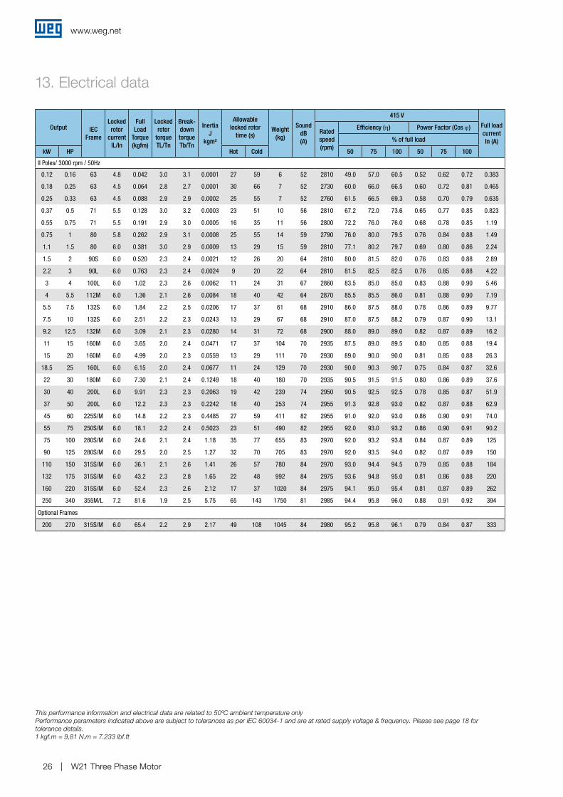
13. Electrical data
Output IEC Frame
Locked rotor
current IL/In
Full Load
Torque (kgfm)
Locked rotor
torque TL/Tn
Break-down torque Tb/Tn
Inertia J
kgm²
Allowable locked rotor
time (s)Weight
(kg)
Sound dB (A)
415 V
Full load current In (A)
Rated speed (rpm)
Efficiency (η) Power Factor (Cos ϕ)
% of full load
kW HP Hot Cold 50 75 100 50 75 100
II Poles/ 3000 rpm / 50Hz
0.12 0.16 63 4.8 0.042 3.0 3.1 0.0001 27 59 6 52 2810 49.0 57.0 60.5 0.52 0.62 0.72 0.383
0.18 0.25 63 4.5 0.064 2.8 2.7 0.0001 30 66 7 52 2730 60.0 66.0 66.5 0.60 0.72 0.81 0.465
0.25 0.33 63 4.5 0.088 2.9 2.9 0.0002 25 55 7 52 2760 61.5 66.5 69.3 0.58 0.70 0.79 0.635
0.37 0.5 71 5.5 0.128 3.0 3.2 0.0003 23 51 10 56 2810 67.2 72.0 73.6 0.65 0.77 0.85 0.823
0.55 0.75 71 5.5 0.191 2.9 3.0 0.0005 16 35 11 56 2800 72.2 76.0 76.0 0.68 0.78 0.85 1.19
0.75 1 80 5.8 0.262 2.9 3.1 0.0008 25 55 14 59 2790 76.0 80.0 79.5 0.76 0.84 0.88 1.49
1.1 1.5 80 6.0 0.381 3.0 2.9 0.0009 13 29 15 59 2810 77.1 80.2 79.7 0.69 0.80 0.86 2.24
1.5 2 90S 6.0 0.520 2.3 2.4 0.0021 12 26 20 64 2810 80.0 81.5 82.0 0.76 0.83 0.88 2.89
2.2 3 90L 6.0 0.763 2.3 2.4 0.0024 9 20 22 64 2810 81.5 82.5 82.5 0.76 0.85 0.88 4.22
3 4 100L 6.0 1.02 2.3 2.6 0.0062 11 24 31 67 2860 83.5 85.0 85.0 0.83 0.88 0.90 5.46
4 5.5 112M 6.0 1.36 2.1 2.6 0.0084 18 40 42 64 2870 85.5 85.5 86.0 0.81 0.88 0.90 7.19
5.5 7.5 132S 6.0 1.84 2.2 2.5 0.0206 17 37 61 68 2910 86.0 87.5 88.0 0.78 0.86 0.89 9.77
7.5 10 132S 6.0 2.51 2.2 2.3 0.0243 13 29 67 68 2910 87.0 87.5 88.2 0.79 0.87 0.90 13.1
9.2 12.5 132M 6.0 3.09 2.1 2.3 0.0280 14 31 72 68 2900 88.0 89.0 89.0 0.82 0.87 0.89 16.2
11 15 160M 6.0 3.65 2.0 2.4 0.0471 17 37 104 70 2935 87.5 89.0 89.5 0.80 0.85 0.88 19.4
15 20 160M 6.0 4.99 2.0 2.3 0.0559 13 29 111 70 2930 89.0 90.0 90.0 0.81 0.85 0.88 26.3
18.5 25 160L 6.0 6.15 2.0 2.4 0.0677 11 24 129 70 2930 90.0 90.3 90.7 0.75 0.84 0.87 32.6
22 30 180M 6.0 7.30 2.1 2.4 0.1249 18 40 180 70 2935 90.5 91.5 91.5 0.80 0.86 0.89 37.6
30 40 200L 6.0 9.91 2.3 2.3 0.2063 19 42 239 74 2950 90.5 92.5 92.5 0.78 0.85 0.87 51.9
37 50 200L 6.0 12.2 2.3 2.3 0.2242 18 40 253 74 2955 91.3 92.8 93.0 0.82 0.87 0.88 62.9
45 60 225S/M 6.0 14.8 2.2 2.3 0.4485 27 59 411 82 2955 91.0 92.0 93.0 0.86 0.90 0.91 74.0
55 75 250S/M 6.0 18.1 2.2 2.4 0.5023 23 51 490 82 2955 92.0 93.0 93.2 0.86 0.90 0.91 90.2
75 100 280S/M 6.0 24.6 2.1 2.4 1.18 35 77 655 83 2970 92.0 93.2 93.8 0.84 0.87 0.89 125
90 125 280S/M 6.0 29.5 2.0 2.5 1.27 32 70 705 83 2970 92.0 93.5 94.0 0.82 0.87 0.89 150
110 150 315S/M 6.0 36.1 2.1 2.6 1.41 26 57 780 84 2970 93.0 94.4 94.5 0.79 0.85 0.88 184
132 175 315S/M 6.0 43.2 2.3 2.8 1.65 22 48 992 84 2975 93.6 94.8 95.0 0.81 0.86 0.88 220
160 220 315S/M 6.0 52.4 2.3 2.6 2.12 17 37 1020 84 2975 94.1 95.0 95.4 0.81 0.87 0.89 262
250 340 355M/L 7.2 81.6 1.9 2.5 5.75 65 143 1750 81 2985 94.4 95.8 96.0 0.88 0.91 0.92 394
Optional Frames
200 270 315S/M 6.0 65.4 2.2 2.9 2.17 49 108 1045 84 2980 95.2 95.8 96.1 0.79 0.84 0.87 333
This performance information and electrical data are related to 50ºC ambient temperature onlyPerformance parameters indicated above are subject to tolerances as per IEC 60034-1 and are at rated supply voltage & frequency. Please see page 18 for tolerance details.1 kgf.m = 9,81 N.m = 7.233 lbf.ft
www.weg.net
W21 Three Phase Motor 27
Output IEC Frame
Locked rotor
current IL/In
Full Load
Torque (kgfm)
Locked rotor
torque TL/Tn
Break-down torque Tb/Tn
Inertia J
kgm²
Allowable locked rotor
time (s)Weight
(kg)
Sound dB (A)
415 V
Full load current In (A)
Rated speed (rpm)
Efficiency (η) Power Factor (Cos ϕ)
% of full load
kW HP Hot Cold 50 75 100 50 75 100
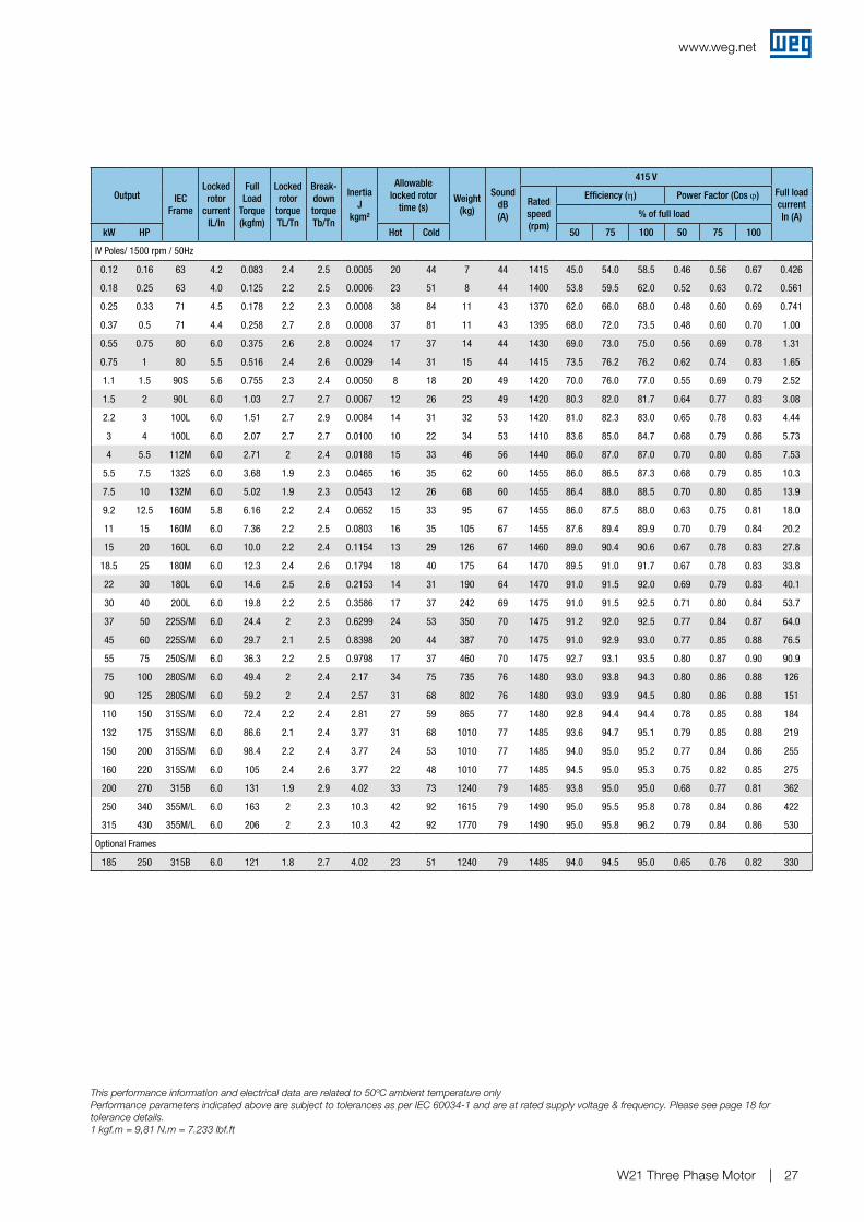
IV Poles/ 1500 rpm / 50Hz
0.12 0.16 63 4.2 0.083 2.4 2.5 0.0005 20 44 7 44 1415 45.0 54.0 58.5 0.46 0.56 0.67 0.426
0.18 0.25 63 4.0 0.125 2.2 2.5 0.0006 23 51 8 44 1400 53.8 59.5 62.0 0.52 0.63 0.72 0.561
0.25 0.33 71 4.5 0.178 2.2 2.3 0.0008 38 84 11 43 1370 62.0 66.0 68.0 0.48 0.60 0.69 0.741
0.37 0.5 71 4.4 0.258 2.7 2.8 0.0008 37 81 11 43 1395 68.0 72.0 73.5 0.48 0.60 0.70 1.00
0.55 0.75 80 6.0 0.375 2.6 2.8 0.0024 17 37 14 44 1430 69.0 73.0 75.0 0.56 0.69 0.78 1.31
0.75 1 80 5.5 0.516 2.4 2.6 0.0029 14 31 15 44 1415 73.5 76.2 76.2 0.62 0.74 0.83 1.65
1.1 1.5 90S 5.6 0.755 2.3 2.4 0.0050 8 18 20 49 1420 70.0 76.0 77.0 0.55 0.69 0.79 2.52
1.5 2 90L 6.0 1.03 2.7 2.7 0.0067 12 26 23 49 1420 80.3 82.0 81.7 0.64 0.77 0.83 3.08
2.2 3 100L 6.0 1.51 2.7 2.9 0.0084 14 31 32 53 1420 81.0 82.3 83.0 0.65 0.78 0.83 4.44
3 4 100L 6.0 2.07 2.7 2.7 0.0100 10 22 34 53 1410 83.6 85.0 84.7 0.68 0.79 0.86 5.73
4 5.5 112M 6.0 2.71 2 2.4 0.0188 15 33 46 56 1440 86.0 87.0 87.0 0.70 0.80 0.85 7.53
5.5 7.5 132S 6.0 3.68 1.9 2.3 0.0465 16 35 62 60 1455 86.0 86.5 87.3 0.68 0.79 0.85 10.3
7.5 10 132M 6.0 5.02 1.9 2.3 0.0543 12 26 68 60 1455 86.4 88.0 88.5 0.70 0.80 0.85 13.9
9.2 12.5 160M 5.8 6.16 2.2 2.4 0.0652 15 33 95 67 1455 86.0 87.5 88.0 0.63 0.75 0.81 18.0
11 15 160M 6.0 7.36 2.2 2.5 0.0803 16 35 105 67 1455 87.6 89.4 89.9 0.70 0.79 0.84 20.2
15 20 160L 6.0 10.0 2.2 2.4 0.1154 13 29 126 67 1460 89.0 90.4 90.6 0.67 0.78 0.83 27.8
18.5 25 180M 6.0 12.3 2.4 2.6 0.1794 18 40 175 64 1470 89.5 91.0 91.7 0.67 0.78 0.83 33.8
22 30 180L 6.0 14.6 2.5 2.6 0.2153 14 31 190 64 1470 91.0 91.5 92.0 0.69 0.79 0.83 40.1
30 40 200L 6.0 19.8 2.2 2.5 0.3586 17 37 242 69 1475 91.0 91.5 92.5 0.71 0.80 0.84 53.7
37 50 225S/M 6.0 24.4 2 2.3 0.6299 24 53 350 70 1475 91.2 92.0 92.5 0.77 0.84 0.87 64.0
45 60 225S/M 6.0 29.7 2.1 2.5 0.8398 20 44 387 70 1475 91.0 92.9 93.0 0.77 0.85 0.88 76.5
55 75 250S/M 6.0 36.3 2.2 2.5 0.9798 17 37 460 70 1475 92.7 93.1 93.5 0.80 0.87 0.90 90.9
75 100 280S/M 6.0 49.4 2 2.4 2.17 34 75 735 76 1480 93.0 93.8 94.3 0.80 0.86 0.88 126
90 125 280S/M 6.0 59.2 2 2.4 2.57 31 68 802 76 1480 93.0 93.9 94.5 0.80 0.86 0.88 151
110 150 315S/M 6.0 72.4 2.2 2.4 2.81 27 59 865 77 1480 92.8 94.4 94.4 0.78 0.85 0.88 184
132 175 315S/M 6.0 86.6 2.1 2.4 3.77 31 68 1010 77 1485 93.6 94.7 95.1 0.79 0.85 0.88 219
150 200 315S/M 6.0 98.4 2.2 2.4 3.77 24 53 1010 77 1485 94.0 95.0 95.2 0.77 0.84 0.86 255
160 220 315S/M 6.0 105 2.4 2.6 3.77 22 48 1010 77 1485 94.5 95.0 95.3 0.75 0.82 0.85 275
200 270 315B 6.0 131 1.9 2.9 4.02 33 73 1240 79 1485 93.8 95.0 95.0 0.68 0.77 0.81 362
250 340 355M/L 6.0 163 2 2.3 10.3 42 92 1615 79 1490 95.0 95.5 95.8 0.78 0.84 0.86 422
315 430 355M/L 6.0 206 2 2.3 10.3 42 92 1770 79 1490 95.0 95.8 96.2 0.79 0.84 0.86 530
Optional Frames
185 250 315B 6.0 121 1.8 2.7 4.02 23 51 1240 79 1485 94.0 94.5 95.0 0.65 0.76 0.82 330
This performance information and electrical data are related to 50ºC ambient temperature onlyPerformance parameters indicated above are subject to tolerances as per IEC 60034-1 and are at rated supply voltage & frequency. Please see page 18 for tolerance details.1 kgf.m = 9,81 N.m = 7.233 lbf.ft
www.weg.net
W21 Three Phase Motor28
Output IEC Frame
Locked rotor
current IL/In
Full Load
Torque (kgfm)
Locked rotor
torque TL/Tn
Break-down torque Tb/Tn
Inertia J
kgm²
Allowable locked rotor
time (s)Weight
(kg)
Sound dB (A)
415 VFull load
current In (A)
Rated speed (rpm)
Efficiency (η) Power Factor (Cos ϕ)
% of full load
kW HP Hot Cold 50 75 100 50 75 100
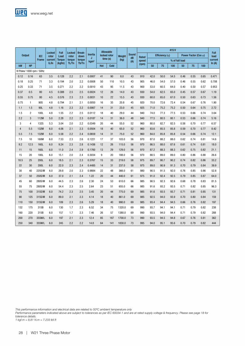
VI Poles/ 1000 rpm / 50Hz
0.12 0.16 63 3.5 0.128 2.2 2.1 0.0007 41 90 8.0 43 910 42.0 50.0 54.5 0.46 0.55 0.65 0.471
0.18 0.25 71 3.3 0.194 2.0 2.2 0.0008 50 110 10.5 43 905 46.0 54.0 57.0 0.46 0.55 0.62 0.708
0.25 0.33 71 3.5 0.271 2.2 2.2 0.0010 43 95 11.5 43 900 53.0 60.5 64.0 0.40 0.50 0.57 0.953
0.37 0.5 80 4.5 0.388 2.5 2.5 0.0024 12 26 14.0 43 930 54.0 62.5 65.0 0.45 0.57 0.67 1.19
0.55 0.75 80 4.5 0.576 2.3 2.3 0.0031 10 22 15.5 43 930 60.0 65.0 67.0 0.50 0.63 0.73 1.56
0.75 1 90S 4.8 0.794 2.1 2.1 0.0050 16 35 20.8 45 920 70.0 72.6 72.4 0.54 0.67 0.76 1.90
1.1 1.5 90L 4.8 1.16 2.3 2.2 0.0067 14 31 23.0 45 925 71.0 75.2 75.2 0.50 0.64 0.75 2.72
1.5 2 100L 4.8 1.55 2.2 2.5 0.0112 18 40 29.0 44 940 74.0 77.3 77.5 0.53 0.66 0.74 3.64
2.2 3 112M 5.0 2.28 2.2 2.3 0.0187 14 31 36.0 48 940 77.5 80.5 80.1 0.53 0.66 0.74 5.16
3 4 132S 5.3 3.04 2.0 2.2 0.0349 20 44 55.0 52 960 80.0 82.7 82.5 0.58 0.70 0.77 6.57
4 5.5 132M 6.0 4.06 2.1 2.3 0.0504 18 40 65.0 52 960 83.6 85.5 85.8 0.59 0.70 0.77 8.42
5.5 7.5 132M 6.0 5.58 2.2 2.4 0.0659 14 31 75.0 52 960 84.0 85.8 85.8 0.54 0.66 0.74 12.1
7.5 10 160M 6.0 7.53 2.3 2.6 0.1221 17 37 103.0 56 970 87.0 88.2 88.0 0.62 0.74 0.81 14.6
9.2 12.5 160L 6.0 9.24 2.3 2.8 0.1436 12 26 115.0 56 970 86.5 88.0 87.6 0.61 0.74 0.81 18.0
11 15 160L 6.0 11.0 2.4 2.9 0.1760 13 29 129.0 56 970 87.2 88.3 88.3 0.62 0.75 0.82 21.1
15 20 180L 6.0 15.1 2.0 2.4 0.3034 9 20 188.0 56 970 88.5 89.0 89.0 0.80 0.86 0.88 26.6
18.5 25 200L 6.0 18.5 2.1 2.3 0.3767 15 33 219.0 58 975 89.7 90.7 90.2 0.74 0.82 0.86 33.2
22 30 200L 6.0 22.0 2.3 2.4 0.4485 14 31 237.0 58 975 89.0 90.9 91.3 0.70 0.79 0.84 39.9
30 40 225S/M 6.0 29.8 2.0 2.3 0.9884 22 48 366.0 61 980 90.5 91.5 92.0 0.76 0.85 0.86 52.8
37 50 250S/M 6.0 37.0 2.1 2.4 1.22 20 44 440.0 61 975 91.0 92.4 92.5 0.79 0.85 0.87 64.0
45 60 280S/M 6.0 44.5 2.3 2.6 2.30 24 53 610.0 66 985 90.5 92.3 92.6 0.68 0.78 0.83 81.5
55 75 280S/M 6.0 54.4 2.3 2.5 2.64 23 51 655.0 66 985 91.6 93.2 93.5 0.71 0.82 0.85 96.3
75 100 315S/M 6.0 74.2 2.3 2.5 3.45 20 44 775.0 69 985 91.6 93.5 93.7 0.71 0.81 0.85 131
90 125 315S/M 6.0 89.0 2.1 2.3 4.14 18 40 861.0 69 985 92.5 94.0 93.9 0.70 0.80 0.84 159
110 150 315S/M 6.0 109 2.3 2.6 5.29 18 40 990.0 69 985 93.4 94.4 94.5 0.66 0.76 0.82 197
132 175 315B 6.0 130 1.7 2.3 6.52 34 75 1320.0 69 990 93.7 94.1 94.1 0.71 0.79 0.82 238
160 220 315B 6.0 157 1.7 2.3 7.46 26 57 1380.0 69 990 93.5 94.0 94.4 0.71 0.79 0.82 288
200 270 355M/L 6.0 197 2.1 2.3 12.4 85 187 1700.0 73 990 93.5 94.5 94.8 0.67 0.76 0.81 362
250 340 355M/L 6.0 245 2.2 2.2 14.8 64 141 1830.0 73 995 94.0 95.1 95.6 0.70 0.79 0.82 444
This performance information and electrical data are related to 50ºC ambient temperature onlyPerformance parameters indicated above are subject to tolerances as per IEC 60034-1 and are at rated supply voltage & frequency. Please see page 18 for tolerance details.1 kgf.m = 9,81 N.m = 7.233 lbf.ft
www.weg.net
W21 Three Phase Motor 29
Output IEC Frame
Locked rotor
current IL/In
Full Load
Torque (kgfm)
Locked rotor
torque TL/Tn
Break-down torque Tb/Tn
Inertia J
kgm²
Allowable locked rotor
time (s)Weight
(kg)
Sound dB (A)
415 VFull load
current In (A)
Rated speed (rpm)
Efficiency (η) Power Factor (Cos ϕ)
% of full load
kW HP Hot Cold 50 75 100 50 75 100
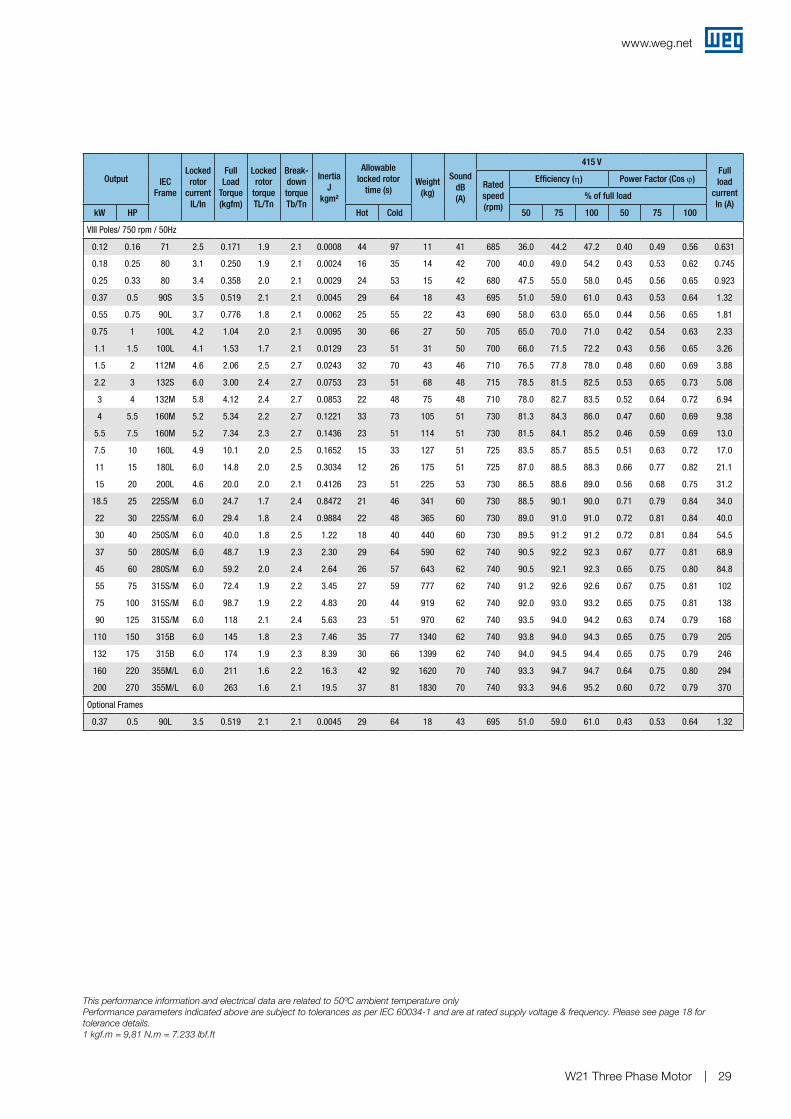
VIII Poles/ 750 rpm / 50Hz
0.12 0.16 71 2.5 0.171 1.9 2.1 0.0008 44 97 11 41 685 36.0 44.2 47.2 0.40 0.49 0.56 0.631
0.18 0.25 80 3.1 0.250 1.9 2.1 0.0024 16 35 14 42 700 40.0 49.0 54.2 0.43 0.53 0.62 0.745
0.25 0.33 80 3.4 0.358 2.0 2.1 0.0029 24 53 15 42 680 47.5 55.0 58.0 0.45 0.56 0.65 0.923
0.37 0.5 90S 3.5 0.519 2.1 2.1 0.0045 29 64 18 43 695 51.0 59.0 61.0 0.43 0.53 0.64 1.32
0.55 0.75 90L 3.7 0.776 1.8 2.1 0.0062 25 55 22 43 690 58.0 63.0 65.0 0.44 0.56 0.65 1.81
0.75 1 100L 4.2 1.04 2.0 2.1 0.0095 30 66 27 50 705 65.0 70.0 71.0 0.42 0.54 0.63 2.33
1.1 1.5 100L 4.1 1.53 1.7 2.1 0.0129 23 51 31 50 700 66.0 71.5 72.2 0.43 0.56 0.65 3.26
1.5 2 112M 4.6 2.06 2.5 2.7 0.0243 32 70 43 46 710 76.5 77.8 78.0 0.48 0.60 0.69 3.88
2.2 3 132S 6.0 3.00 2.4 2.7 0.0753 23 51 68 48 715 78.5 81.5 82.5 0.53 0.65 0.73 5.08
3 4 132M 5.8 4.12 2.4 2.7 0.0853 22 48 75 48 710 78.0 82.7 83.5 0.52 0.64 0.72 6.94
4 5.5 160M 5.2 5.34 2.2 2.7 0.1221 33 73 105 51 730 81.3 84.3 86.0 0.47 0.60 0.69 9.38
5.5 7.5 160M 5.2 7.34 2.3 2.7 0.1436 23 51 114 51 730 81.5 84.1 85.2 0.46 0.59 0.69 13.0
7.5 10 160L 4.9 10.1 2.0 2.5 0.1652 15 33 127 51 725 83.5 85.7 85.5 0.51 0.63 0.72 17.0
11 15 180L 6.0 14.8 2.0 2.5 0.3034 12 26 175 51 725 87.0 88.5 88.3 0.66 0.77 0.82 21.1
15 20 200L 4.6 20.0 2.0 2.1 0.4126 23 51 225 53 730 86.5 88.6 89.0 0.56 0.68 0.75 31.2
18.5 25 225S/M 6.0 24.7 1.7 2.4 0.8472 21 46 341 60 730 88.5 90.1 90.0 0.71 0.79 0.84 34.0
22 30 225S/M 6.0 29.4 1.8 2.4 0.9884 22 48 365 60 730 89.0 91.0 91.0 0.72 0.81 0.84 40.0
30 40 250S/M 6.0 40.0 1.8 2.5 1.22 18 40 440 60 730 89.5 91.2 91.2 0.72 0.81 0.84 54.5
37 50 280S/M 6.0 48.7 1.9 2.3 2.30 29 64 590 62 740 90.5 92.2 92.3 0.67 0.77 0.81 68.9
45 60 280S/M 6.0 59.2 2.0 2.4 2.64 26 57 643 62 740 90.5 92.1 92.3 0.65 0.75 0.80 84.8
55 75 315S/M 6.0 72.4 1.9 2.2 3.45 27 59 777 62 740 91.2 92.6 92.6 0.67 0.75 0.81 102
75 100 315S/M 6.0 98.7 1.9 2.2 4.83 20 44 919 62 740 92.0 93.0 93.2 0.65 0.75 0.81 138
90 125 315S/M 6.0 118 2.1 2.4 5.63 23 51 970 62 740 93.5 94.0 94.2 0.63 0.74 0.79 168
110 150 315B 6.0 145 1.8 2.3 7.46 35 77 1340 62 740 93.8 94.0 94.3 0.65 0.75 0.79 205
132 175 315B 6.0 174 1.9 2.3 8.39 30 66 1399 62 740 94.0 94.5 94.4 0.65 0.75 0.79 246
160 220 355M/L 6.0 211 1.6 2.2 16.3 42 92 1620 70 740 93.3 94.7 94.7 0.64 0.75 0.80 294
200 270 355M/L 6.0 263 1.6 2.1 19.5 37 81 1830 70 740 93.3 94.6 95.2 0.60 0.72 0.79 370
Optional Frames
0.37 0.5 90L 3.5 0.519 2.1 2.1 0.0045 29 64 18 43 695 51.0 59.0 61.0 0.43 0.53 0.64 1.32
This performance information and electrical data are related to 50ºC ambient temperature onlyPerformance parameters indicated above are subject to tolerances as per IEC 60034-1 and are at rated supply voltage & frequency. Please see page 18 for tolerance details.1 kgf.m = 9,81 N.m = 7.233 lbf.ft
www.weg.net
W21 Three Phase Motor30
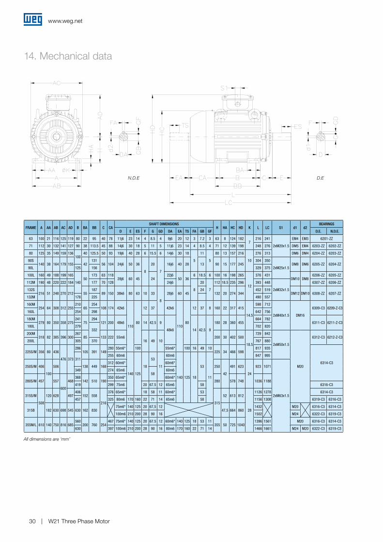
14. Mechanical data
FRAME A AA AB AC AD B BA BB C CASHAFT DIMENSIONS
H HA HC HD K L LC S1 d1 d2BEARINGS
D E ES F G GD DA EA TS FA GB GF D.E. N.D.E.
63 100 21 116 125 119 80 22 95 40 78 11j6 23 14 4 8.5 4 9j6 20 12 3 7.2 3 63 8 124 1827
216 241
2xM20x1.5
EM4 EM3 6201-ZZ
71 112 30 132 141 127 90 38 113.5 45 88 14j6 30 18 5 11 5 11j6 23 14 4 8.5 4 71 12 139 198 248 276 DM5 EM4 6203-ZZ 6202-ZZ
80 125 35 149 159 136100
40 125.5 50 93 19j6 40 28 6 15.5 6 14j6 30 18
5
11
5
80 13 157 216
10
276 313 DM6 DM4 6204-ZZ 6203-ZZ
90S140 38 164 179 155 42
13156 104 24j6 50 36
8
20
7
16j6 40 28 13 90 15 177 245304 350
2xM25x1.5DM8 DM6 6205-ZZ 6204-ZZ
90L 125 156 329 375
100L 160 49 188 199 165
14050
173 63 11828j6 60 45 24
22j650 36
6 18.5 6 100 16 198 265
12
376 431DM10 DM8
6206-ZZ 6205-ZZ
112M 190 48 220 222 184 177 70 128 24j6
8
20
7
112 18.5 235 296 393 448
2xM32x1.5
6307-ZZ 6206-ZZ
132S216 51 248 270 212 55
18789 150 38k6 80 63 10 33
8
28j6 60 4524
132 20 274 344452 519
DM12 DM10 6308-ZZ 6207-ZZ132M 178 225 490 557
160M254 64 308 312 255
21065
254108 174 42k6
11080
12 37 42k6
11080
12 37 8 160 22 317 415
14.5
598 712
2xM40x1.5 DM16
6309-C3 6209-Z-C3160L 254 298 642 756
180M279 80 350 358 275
24175
294121 200 48k6 14 42.5 9
48k6 14 42.5 9
180 28 360 455664 782
6311-C3 6211-Z-C3180L 279
332702 820
200M318 82 385 396 300
26785 133 222 55m6
16 49 10200 30 402 500
18.5
729 842
2xM50x1.5
M20
6312-C3 6212-Z-C3200L 305 370 767 880
225S/M 356 80 436
476 373
286105 391 149
280 55m6* 100 55m6* 100 16 49 10225 34 466 598
817 935
6314-C3311
255 60m6
140 125
18
53
11
60m6
140 125 18
53
11
847 995
250S/M 406
100
506 138 449 168312 60m6* 60m6*
250
42
491 623
24
923 1071
2xM63x1.5
349 274 65m658
60m6
280S/M 457 557
600
468368
142 510 190350 65m6* 60m6*
280 578 748 1036 1188419 299 75m6 20 67.5 12 65m6 58 6316-C3
315S/M
508
120 628 497406
152 558
216
376 65m6* 18 58 11 60m6* 53
315
52 613 812
28
1126 1278 6314-C3
457 325 80m6 170 160 22 71 14 65m6 58 1156 1308 6319-C3 6316-C3
315B 182 630 698 545 630 162 83075m6* 140 125 20 67,5 12
47,5 664 8601432 M20 6316-C3 6314-C3
100m6 210 200 28 90 16 1502 M24 6322-C3 6319-C3
355M/L 610 140 750 816 685560
200 760 254467 75m6* 140 125 20 67.5 12 60m6* 140 125 18 53 11
355 50 725 10401396 1561 M20 6316-C3 6314-C3
630 397 100m6 210 200 28 90 16 80m6 170 160 22 71 14 1466 1661 M24 M20 6322-C3 6319-C3
N.D.E D.E
All dimensions are ‘mm’
www.weg.net
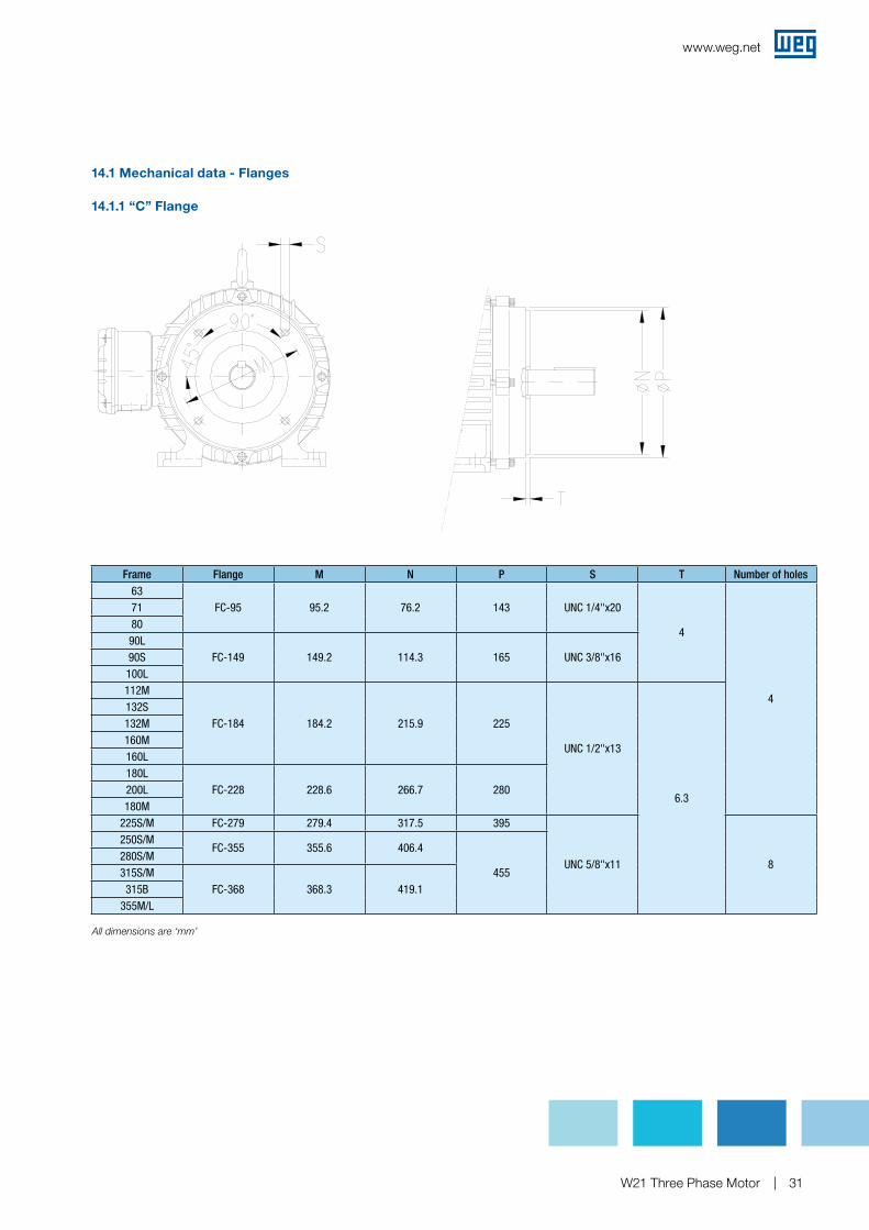
W21 Three Phase Motor 31
Frame Flange M N P S T Number of holes63
FC-95 95.2 76.2 143 UNC 1/4"x20
4
4
718090L
FC-149 149.2 114.3 165 UNC 3/8"x1690S100L112M
FC-184 184.2 215.9 225
UNC 1/2"x13
6.3
132S132M160M160L180L
FC-228 228.6 266.7 280200L180M
225S/M FC-279 279.4 317.5 395
UNC 5/8"x11 8
250S/MFC-355 355.6 406.4
455280S/M315S/M
FC-368 368.3 419.1315B355M/L
14.1.1 “C” Flange
14.1 Mechanical data - Flanges
Flange FF
Flange C
All dimensions are ‘mm’
www.weg.net
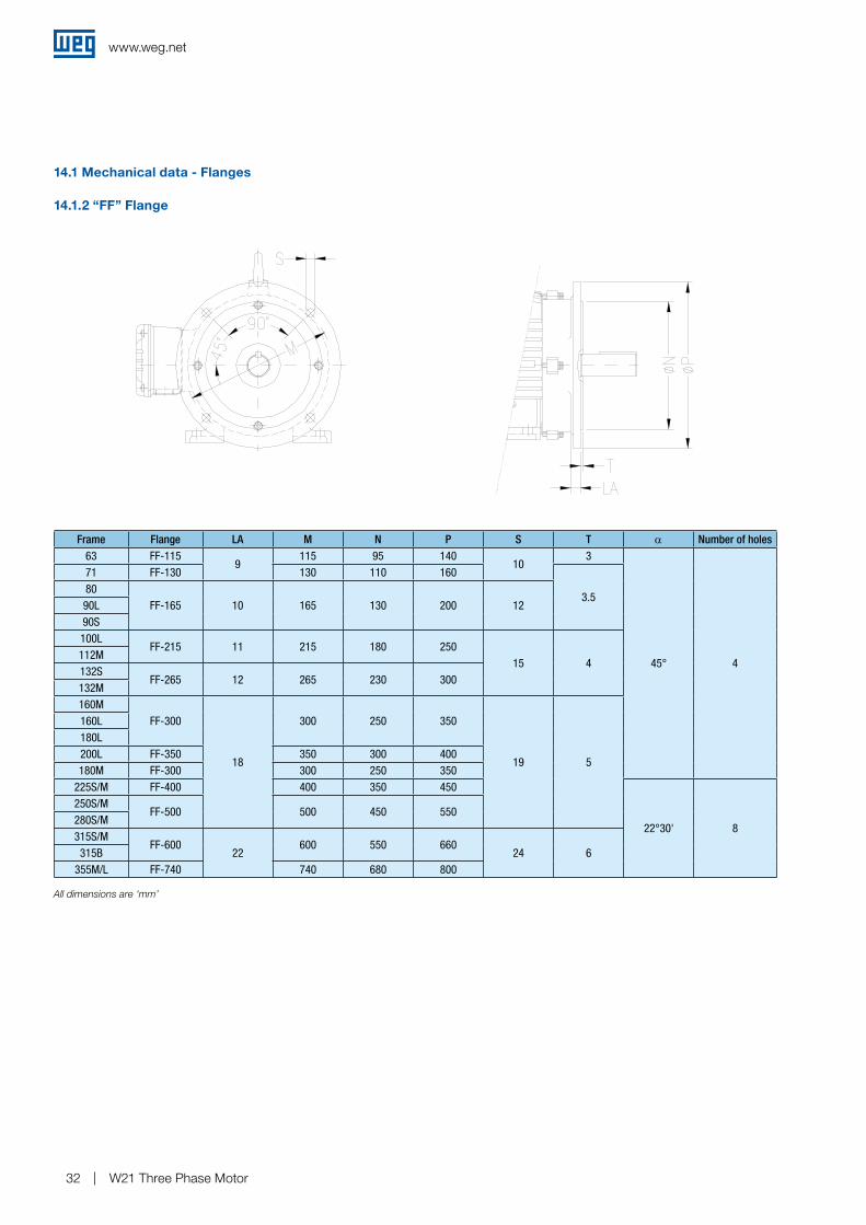
W21 Three Phase Motor32
Frame Flange LA M N P S T α Number of holes63 FF-115
9115 95 140
103
45° 4
71 FF-130 130 110 160
3.580
FF-165 10 165 130 200 1290L90S100L
FF-215 11 215 180 25015 4
112M132S
FF-265 12 265 230 300132M160M
FF-300
18
300 250 350
19 5
160L180L200L FF-350 350 300 400180M FF-300 300 250 350
225S/M FF-400 400 350 450
22°30' 8
250S/MFF-500 500 450 550
280S/M315S/M
FF-60022
600 550 66024 6315B
355M/L FF-740 740 680 800
14.1.2 “FF” Flange
14.1 Mechanical data - FlangesFlange FF
All dimensions are ‘mm’
www.weg.net
W21 Three Phase Motor 33
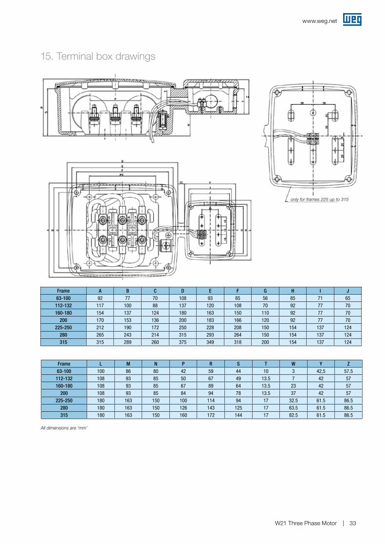
15. Terminal box drawings
Frame A B C D E F G H I J63-100 92 77 70 108 93 85 56 85 71 65112-132 117 100 88 137 120 108 70 92 77 70160-180 154 137 124 180 163 150 110 92 77 70
200 170 153 136 200 183 166 120 92 77 70225-250 212 190 172 250 228 208 150 154 137 124
280 265 243 214 315 293 264 150 154 137 124315 315 289 260 375 349 318 200 154 137 124
Frame L M N P R S T W Y Z63-100 100 86 80 42 59 44 10 3 42,5 57.5112-132 108 93 85 50 67 49 13.5 7 42 57160-180 108 93 85 67 89 64 13.5 23 42 57
200 108 93 85 84 94 78 13.5 37 42 57225-250 180 163 150 100 114 94 17 32.5 61.5 86.5
280 180 163 150 126 143 125 17 63.5 61.5 86.5315 180 163 150 160 172 144 17 82.5 61.5 86.5
only for frames 225 up to 315
All dimensions are ‘mm’
www.weg.net
W21 Three Phase Motor34
16. Features and benefits
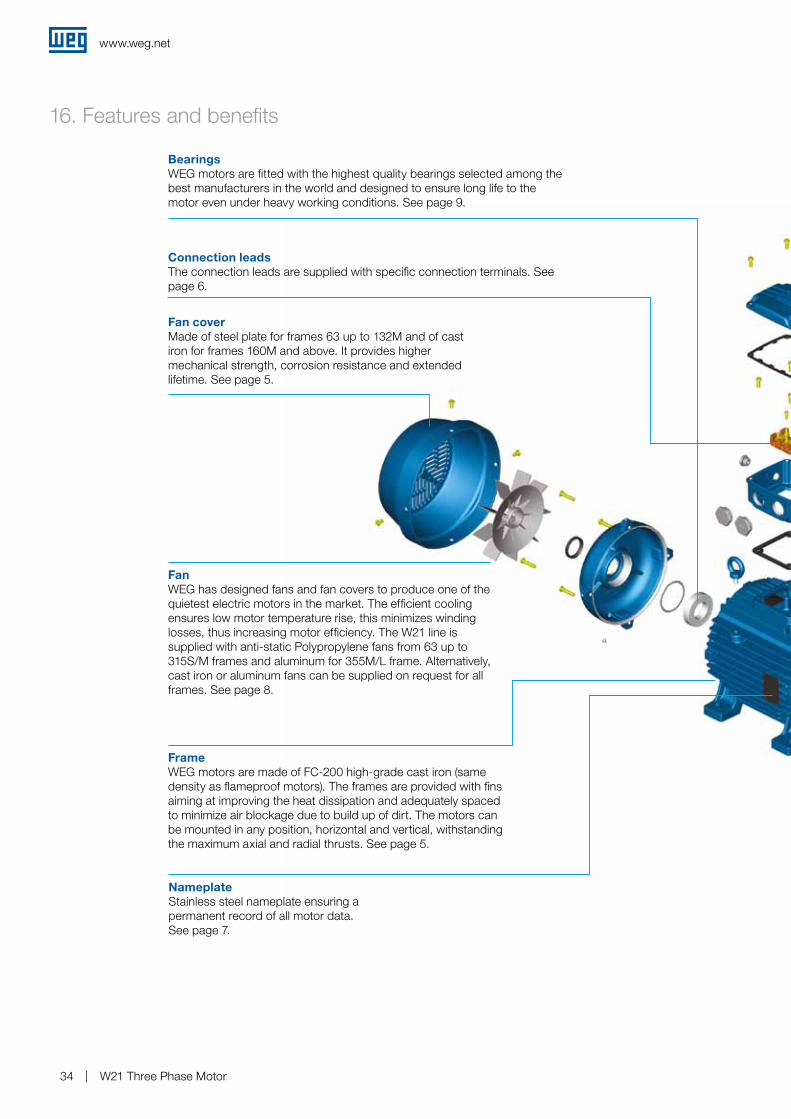
BearingsWEG motors are fitted with the highest quality bearings selected among the best manufacturers in the world and designed to ensure long life to the motor even under heavy working conditions. See page 9.
Connection leadsThe connection leads are supplied with specific connection terminals. See page 6.
Fan coverMade of steel plate for frames 63 up to 132M and of cast iron for frames 160M and above. It provides higher mechanical strength, corrosion resistance and extended lifetime. See page 5.
FanWEG has designed fans and fan covers to produce one of the quietest electric motors in the market. The efficient cooling ensures low motor temperature rise, this minimizes winding losses, thus increasing motor efficiency. The W21 line is supplied with anti-static Polypropylene fans from 63 up to 315S/M frames and aluminum for 355M/L frame. Alternatively, cast iron or aluminum fans can be supplied on request for all frames. See page 8.
FrameWEG motors are made of FC-200 high-grade cast iron (same density as flameproof motors). The frames are provided with fins aiming at improving the heat dissipation and adequately spaced to minimize air blockage due to build up of dirt. The motors can be mounted in any position, horizontal and vertical, withstanding the maximum axial and radial thrusts. See page 5.
NameplateStainless steel nameplate ensuring a permanent record of all motor data. See page 7.
www.weg.net
W21 Three Phase Motor 35
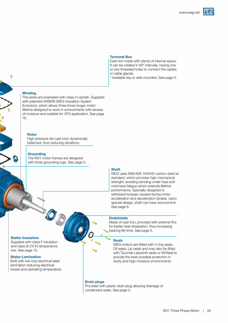
WindingThe wires are enameled with class H varnish. Supplied with patented WISE® (WEG Insulation System Evolution), which allows three times longer motor lifetime designed to work in environments with excess of moisture and suitable for VFD application. See page 16.
Stator InsulationSupplied with class F insulation and class B (70 K) temperature rise. See page 15.
RotorHigh pressure die cast rotor dynamically balanced, thus reducing vibrations.
Stator LaminationBuilt with low loss electrical steel lamination reducing electrical losses and operating temperature.
Terminal BoxCast iron made with plenty of internal space. It can be rotated in 90º intervals, having one or two threaded holes to connect the cables or cable glands.* Available top or side mounted. See page 5.
Shaft WEG uses SAE/AISI 1040/45 carbon steel as standard, which provides high mechanical strenght, avoiding bending under load and minimizes fatigue which extends lifetime performance. Specially designed to withstand torques caused during motor acceleration and deceleration (brake). Upon special design, shaft can have second end. See page 9.
EndshieldsMade of cast iron, provided with external fins for better heat dissipation, thus increasing bearing life time. See page 5.
SealsWEG motors are fitted with V-ring seals, Oil seals, Lip seals and may also be fitted with Taconite Labyrinth seals or W3Seal to provide the best possible protection in dusty and high moisture environments.
Drain plugs Provided with plastic drain plug allowing drainage of condensed water. See page 5.
GroundingThe W21 motor frames are designed with three grounding lugs. See page 5.
013.
00/
0920
09 -
The
val
ues
show
n ar
e su
bje
ct to
cha
nge
with
out p
rior
notic
e.
WEG Worldwide Operations
ARGENTINAWEG EQUIPAMIENTOS ELECTRICOS S.A.(Headquarters San Francisco-Cordoba)Sgo. Pampiglione 4849Parque Industrial San Francisco2400 - San FranciscoPhone(s): +54 (3564) 421484Fax: +54 (3564) [email protected]/ar
AUSTRALIAWEG AUSTRALIA PTY. LTD.3 Dalmore DriveCarribean Park Industrial EstateScoresby VIC 3179 - MelbournePhone(s): 61 (3) 9765 4600Fax: 61 (3) 9753 [email protected]/au
BELGIUM WEG BENELUX S.A.Rue de l’Industrie 30 D, 1400 NivellesPhone(s): + 32 (67) 88-8420Fax: + 32 (67) 84-1748 [email protected]/be
CHILEWEG CHILE S.A.Los Canteros 8600 La Reina - SantiagoPhone(s): (56-2) 784 8900Fax: (56-2) 784 [email protected]/cl
CHINAWEG (NANTONG) ELECTRIC MOTOR MANUFACTURING CO., LTD.No. 128# - Xinkai South Road,Nantong Economic & Technical Development Zone, Nantong, Jiangsu Province. Phone(s): (86) 0513-85989333Fax: (86) [email protected]/cn
COLOMBIAWEG COLOMBIA LTDACalle 46A N82 - 54Portería II - Bodega 7 - San Cayetano II - BogotáPhone(s): (57 1) 416 0166Fax: (57 1) 416 [email protected]/co
FRANCEWEG FRANCE SASZI de Chenes – Le Loup13 Rue du Morellon – BP 73838297 Saint Quentin FallavierPhone(s): +33 (0) 4 74 99 11 35Fax: +33 (0) 4 74 99 11 [email protected]/fr
GERMANYWEG GERMANY GmbHIndustriegebiet Turnich 3Geigerstrasse 7D-50169 Kerpen-TurnichPhone(s): +49 (0) 2237 9291-0Fax: +49 (0) 2237 [email protected]/de
INDIAWEG Electric (India) Pvt. Ltd.#38, Ground Floor, 1st Main Road, Lower Palace Orchards,Bangalore – 560 003Phone(s): +91-80-4128 2007 +91-80-4128 2006 Fax: +91-80-2336 7624 [email protected]/in
ITALYWEG ITALIA S.R.L.V.le Brianza 20 - 20092 - Cinisello Balsamo - MilanoPhone(s): (39) 02 6129-3535Fax: (39) 02 [email protected]/it
JAPANWEG ELECTRIC MOTORSJAPAN CO., LTD.Matsumoto Bldg. 2F, 3-23-7 Kamata, Ohta-ku,Tokyo, Japan 144-0052Phone(s): (81) 3 3736-2998Fax: (81) 3 [email protected]/jp
MEXICOWEG MEXICO, S.A. DE C.V.Carretera Jorobas-Tula Km. 3.5, Manzana 5, Lote 1 Fraccionamiento Parque Industrial - Huehuetoca, Estado de México - C.P. 54680Phone(s): + 52 (55) 5321 4275Fax: + 52 (55) 5321 [email protected]/mx
NETHERLANDSWEG NETHERLANDS Sales Office of WEG Benelux S.A.Hanzepoort 23C 7575 DB OldenzaalPhone(s): +31 (0) 541-571080Fax: +31 (0) [email protected]/nl
PORTUGALWEG EURO - INDÚSTRIA ELÉCTRICA, S.A.Rua Eng. Frederico UlrichApartado 6074 4476-908 - MaiaPhone(s): +351 229 477 705Fax: +351 229 477 [email protected]/pt
RUSSIAWEG RUSSIA Pochainskaya Str. 17 Nizhny Novgorod 603001 - Russia Phone(s): +7-831-2780425 Fax: [email protected] www.weg.net/ru
SPAINWEG IBERIA S.L. Avenida de la Industria,2528823 Coslada - MadridPhone(s) : (34) 916 553 008Fax : (34) 916 553 [email protected]/es
SINGAPOREWEG SINGAPORE PTE LTD159, Kampong Ampat, #06-02A KA PLACE. Singapore 368328.Phone(s): +65 6858 9081Fax: +65 6858 [email protected]/sg
SWEDENWEG SCANDINAVIA ABBox 10196Verkstadgatan 9434 22 KungsbackaPhone(s): (46) 300 73400Fax: (46) 300 [email protected]/se
UKWEG ELECTRIC MOTORS (U.K.) LTD.28/29 Walkers RoadManorside Industrial EstateNorth Moons Moat - RedditchWorcestershire B98 9HEPhone(s): 44 (0)1527 596-748Fax: 44 (0)1527 [email protected]/uk
UNITED ARAB EMIRATESWEG MIDDLE EAST FZEJAFZA – JEBEL ALI FREE ZONETower 18, 19th Floor, Office LB181905Dubai – United Arab [email protected]/ae
USAWEG ELECTRIC CORP. 1327 Northbrook Parkway, Suite 490Suwanee 30024Phone(s): 1-770-338-5656Fax: [email protected] www.weg.net/us
VENEZUELAWEG INDUSTRIAS VENEZUELA C.A.Avenida 138-AEdificio Torre Banco Occidental de Descuento, Piso 6 Oficina 6-12Urbanizacion San Jose de TarbesZona Postal 2001Valencia, Edo. CaraboboPhone(s): (58) 241 8210582 (58) 241 8210799 (58) 241 8211457Fax: (58) 241 [email protected]/ve
WEG Equipamentos Elétricos S.A.International Division Av. Prefeito Waldemar Grubba, 3000 89256-900 - Jaraguá do Sul - SC - Brazil Phone: 55 (47) 3276-4002 Fax: 55 (47) 3276-4060 www.weg.net